

Page 1
Toshiba G8000 Series UPS
Installation Planning Guide for 300kVA UPS
Standard System: 480V Input, 480Y/277V Output
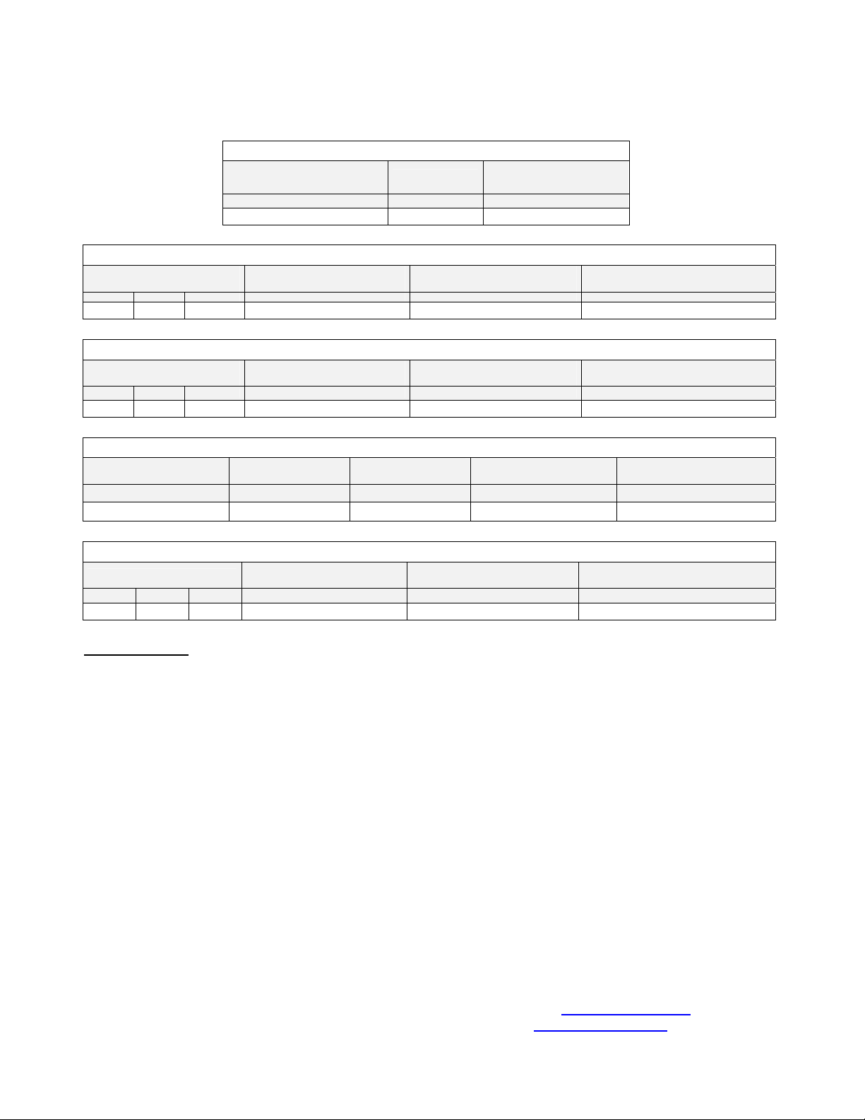
General Mechanical Information
Dimensions
(W x D x H)
Inches Lbs. Btu/Hr
Weight
82.7 x 35.4 x 78.75 4,630 76,184
Primary AC Input (480V 3-Phase / 3-Wire)
Maximum Input Power
Demand
kVA PF Amps Amps AWG or kcmil at 75º C Temp. Rating Feet
300 >0.98 361 500 AT (2) x 4/0 380
External Overcurrent
Protection
Suggested Minimum Feeder
Wire Size – Per Phase
Alternate (Bypass) AC Input (480V 3-Phase / 4-Wire)
Maximum Input Power
Demand
kVA PF Amps Amps AWG or kcmil at 75º C Temp. Rating Feet
300 0.8 361 500 AT (2) x 2/0 / (2) x 350 380
External Overcurrent
Protection
Suggested Minimum Feeder
Wire Size – Per Phase / Neutral
Battery Input (360VDC Nominal)
Battery Capacity Required
for Full Load Output
kWB Amps DC Amps AWG or kcmil at 75º C Temp. Rating Feet
255.3 887 1000 AT (2) x 4/0 per battery cabinet 70
Maximum Discharge
at Full Load Output
External Overcurrent
Protection
AC Output (480/277V 3-Phase / 4-Wire)
Rated Output Power
kVA PF Amps Amps AWG or kcmil at 75º C Temp. Rating Feet
External Overcurrent
Protection
300 0.8 361 500 AT (2) x 4/0 / (2) x 350 380
Suggested Minimum Feeder
Wire Size – Per Phase / Neutral
Important Notes:
1. Maximum Current required at Primary AC Input based on full
load output and maximum battery charging current.
2. Output load conductors are to be installed in separate
conduit from input conductors.
3. Control wires and power wires are to be installed in separate
conduits.
4. Recommended AC input and output overcurrent protection
based on continuous full load current per NEC.
5. Wiring shall comply with all applicable national and local
electrical codes.
6. Grounding conductors to be sized per NEC Article 250-122.
Neutral conductors to be sized per NEC Article 310.15.
- Primary AC Input: 3φ, 4-wire + ground.
- Alternate AC Input: 3φ, 4-wire + ground.
- AC Output: 3φ, 4-wire + ground.
- DC Input: 2-wire (Positive/Negative) + ground.
7. Nominal battery voltage based on the use of VRLA type
batteries (2.0 volts/cell nominal).
8. Maximum battery discharge current based on lowest
permissible discharge voltage of 1.6 VPC.
9. DC wires should be sized to allow not more than a 2-volt
drop at maximum discharge current.
10. Weights do not include batteries or other auxiliary equipment
external to the UPS.
11. Sizing calculations based on the following assumptions:
- Not more than 3 current-carrying conductors installed in steel
conduit in ambient temperature of 30 degrees C.
- Temperature rating of conductors and terminals: 90 deg. C.
- Feeder distance calculations based on NEC Tables 8 and 9
data, allowing for 2% AC voltage drop.
- Reference: 2002 NEC Handbook. Consult latest edition of
applicable national and local codes for possible variations.
12. Ratings of wires and overcurrent devices are suggested
minimums. Consult with a registered Professional Engineer
within your local area for proper size selections.
13. More than one Battery Cabinet will require a DC Junction box
for all battery cabinet connections.
TOSHIBA INTERNATIONAL CORPORATION
13131 West Little York Road
Houston, TX 77041
Telephone: (800) 231-1412
Fax: (713) 896-5212
Corporate Web Site: www.tic.toshiba.com
Group Web Site: www.toshibaups.com
Rev. 1.03 Page 1 of 1 G8000-IPG-300kVA
Approximate Full-
Load Heat Loss
Suggested Maximum Feeder Length
For Min. Wire Size in Steel Conduit
Suggested Maximum Feeder Length
For Min. Wire Size in Steel Conduit
Suggested Minimum Feeder
Wire Size – Per Phase
Suggested Maximum Feeder Length
For Min. Wire Size in Steel Conduit
Suggested Maximum Feeder Length For
Min. Wire Size in Steel Conduit
 Loading...