

Page 1
TOSHIBA Transistor Silicon PNP Epitaxial Type
2SA2065
2SA2065
High-Speed Switching Applications
DC-DC Converter Applications
Strobe Applications
• High DC current gain: h
• Low collector-emitter saturation voltage: V
• High-speed switching: t
Maximum Ratings
Characteristics Symbol Rating Unit
Collector-base voltage V
Collector-emitter voltage V
Emitter-base voltage V
Collector current
Base current IB −150 mA
Collector power
dissipation
Junction temperature Tj 150 °C
Storage temperature range T
= 200 to 500 (IC = −0.15 A)
FE
= −0.14 V (max)
= 37 ns (typ.)
f
CE (sat)
(Ta = 25°C)
CBO
CEO
EBO
DC IC −1.5
Pulse I
t = 10 s 750
DC
−2.5
CP
P
C
(Note 1)
stg
−20 V
−20 V
−7 V
500
−55 to 150 °C
A
mW
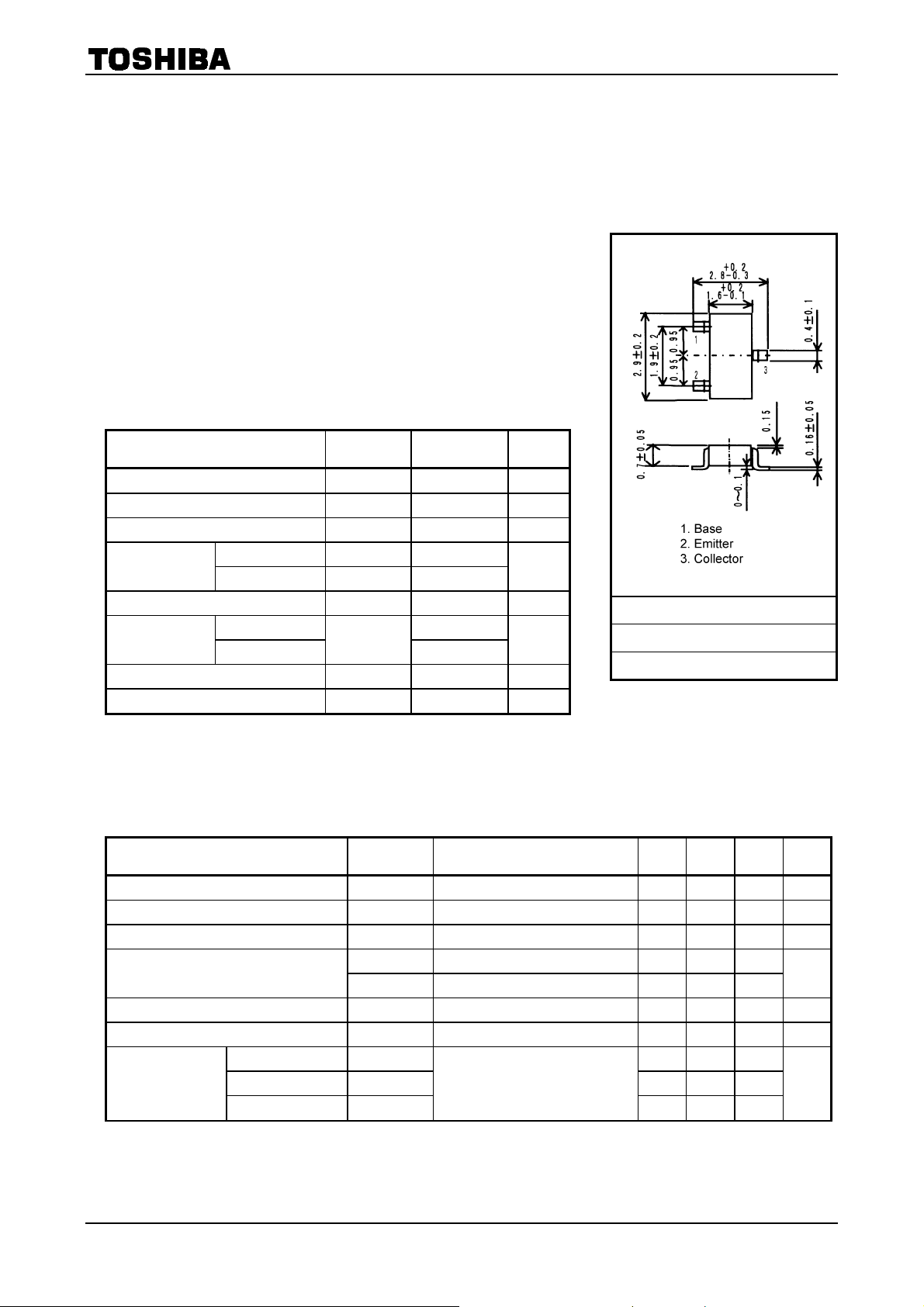
Unit: mm
JEDEC ―
JEITA ―
TOSHIBA 2-3S1A
Weight: 0.01 g (typ.)
Note 1: Mounted on FR4 board (glass epoxy, 1.6 mm thick, Cu area:
645 mm
2
)
Electrical Characteristics
Collector cut-off current I
Emitter cut-off current I
Collector-emitter breakdown voltage V
DC current gain
Collector-emitter saturation voltage V
Base-emitter saturation voltage V
Switching time
Characteristics Symbol Test Condition Min Typ. Max Unit
Rise time tr ― 40 ―
Storage time t
Fall time t
(Ta = 25°C)
VCB = −20 V, IE = 0 ― ― −100 nA
CBO
VEB = −7 V, IC = 0 ― ― −100 nA
EBO
(BR) CEO
hFE (1) VCE = −2 V, IC = −0.15 A 200 ― 500
h
IC = −10 mA, IB = 0 −20 ― ― V
(2) VCE = −2 V, IC = −0.5 A 125 ― ―
FE
IC = −0.5 A, IB = −17 mA ― ― −0.14 V
CE (sat)
IC = −0.5 A, IB = −17 mA ― ― −1.10 V
BE (sat)
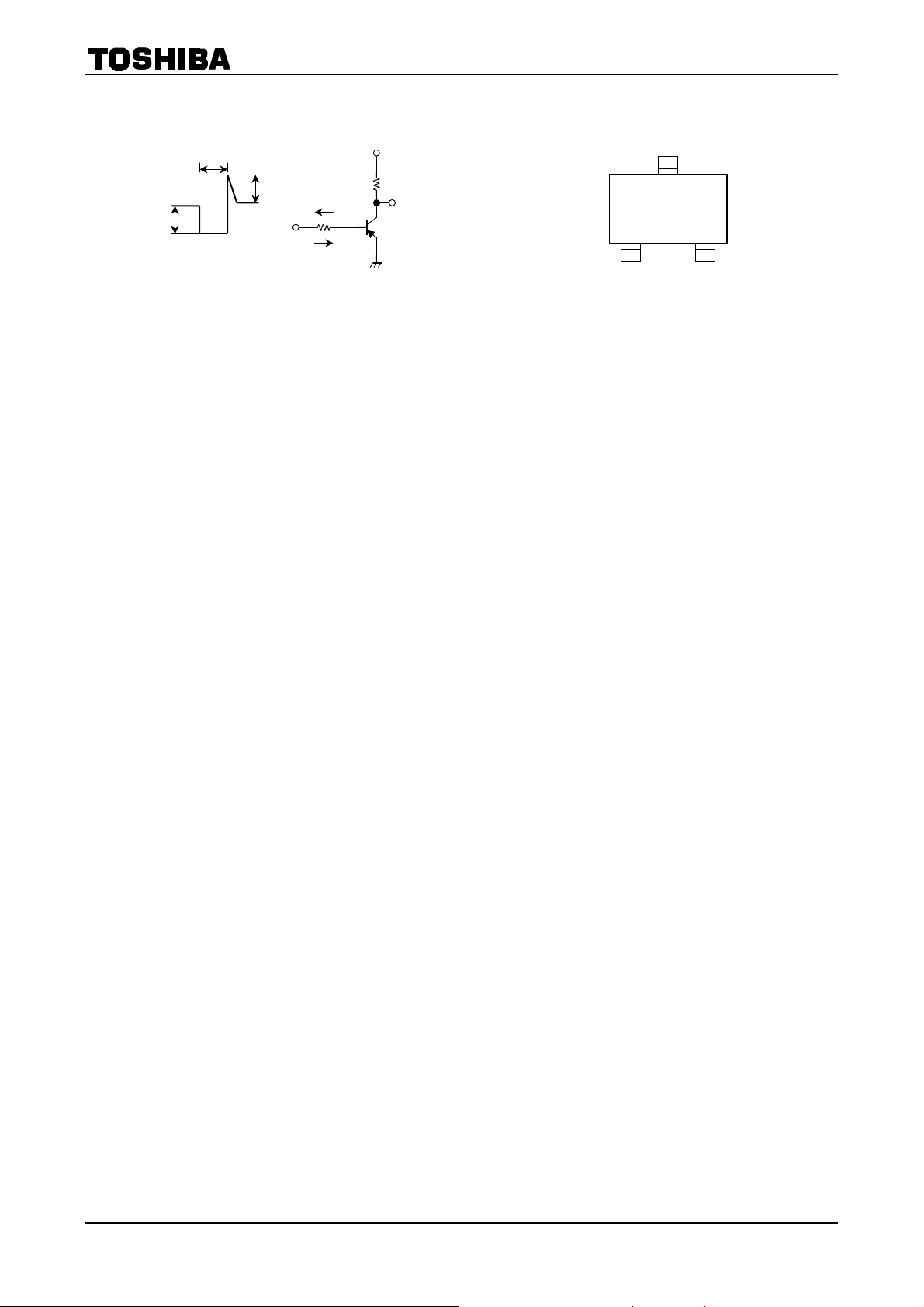
See Figure 1 circuit diagram.
≈ −10 V, RL = 20 Ω
V
― 135 ―
stg
f
CC
= IB2 = −17 mA
−I
B1
ns
― 37 ―
1
2001-10-29
Page 2
Marking
2SA2065
B1
B2
VCC
L
R
Output
20 µs
I
B1
Duty cycle < 1%
IB2
I
Input
I
Figure 1 Switching Time Test Circuit &
Timing Chart
W K
2
2001-10-29
Page 3
2SA2065
−1.6
−1.2
(A)
C
−0.8
Common emitter
Ta = 25°C
Single nonrepetitive
pulse
−0.4
Collector current I
0
0 −0.2 −0.4 −0.6 −0.8
Collector-emitter voltage VCE (V)
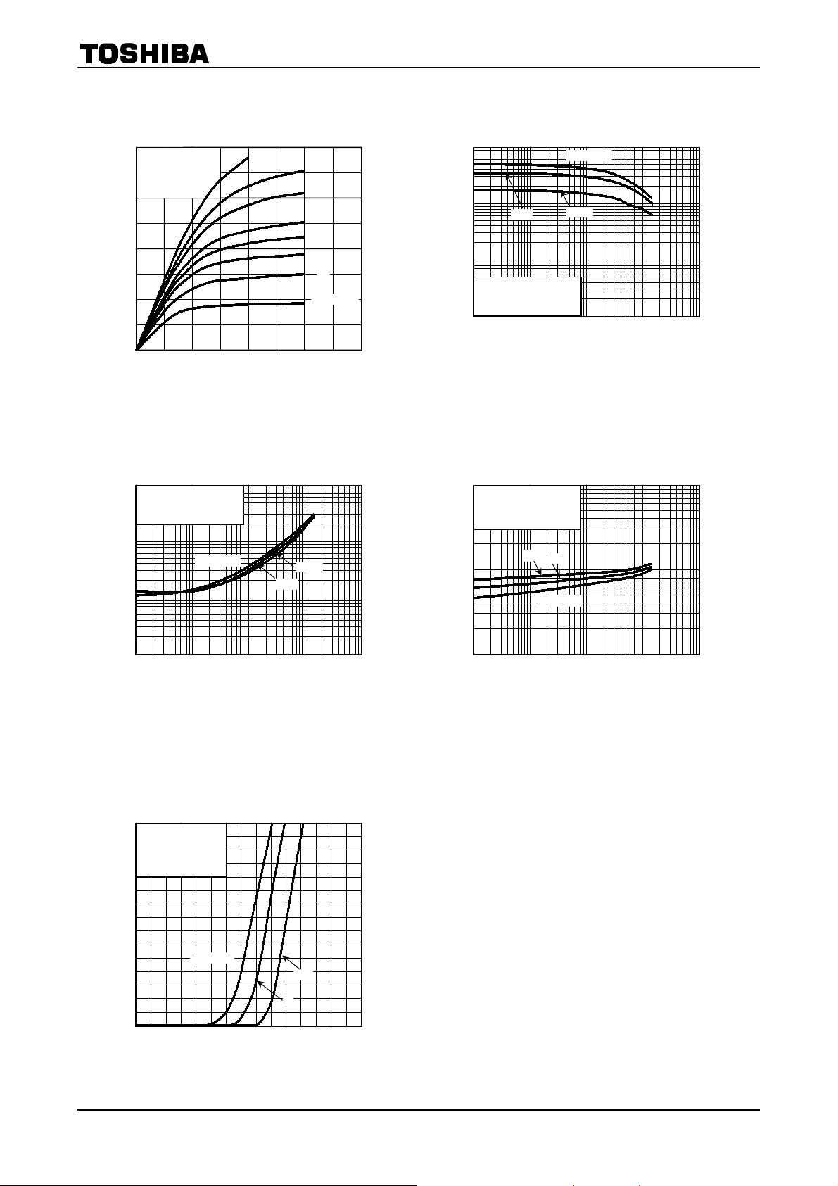
– VCE
I
C
−30
−20
−15
−10
−8
−6
−4
I
= −2 mA
B
1000
FE
100
25
10
DC current gain h
Common emitter
V
= −2 V
CE
Single nonrepetitive pulse
1
−0.001 −0.01 −0.1 −1 −10
Collector current IC (A)
– IC
h
FE
Ta = 100°C
−55
−1
Common emitter
IC/I
= 30
B
Single nonrepetitive pulse
−0.1
(V)
Ta = 100°C
CE (sat)
−0.01
V
V
CE (sat)
– IC
25
−55
−10
Common emitter
IC/I
= 30
B
Single nonrepetitive pulse
(V)
BE (sat)
V
−1
−55
Ta = 100°C
V
25
BE (sat)
– IC
Collector-emitter saturation voltage
−0.001 −0.01 −0.1 −1 −10
Collector current IC (A)
−0.001
Base-emitter saturation voltage
−0.1
−0.001 −0.01 −0.1 −1 −10
Collector current IC (A)
−1.5
−1.2
(A)
C
−0.9
−0.6
Collector current I
−0.3
Common emitter
V
= −2 V
CE
Single nonrepetitive
pulse
Ta = 100°C
0
0
−0.3 −0.6 −0.9 −1.5
Base-emitter voltage VBE (V)
– VBE
I
C
−55
25
−1.2
3
2001-10-29
Page 4
2SA2065
1000
r
th
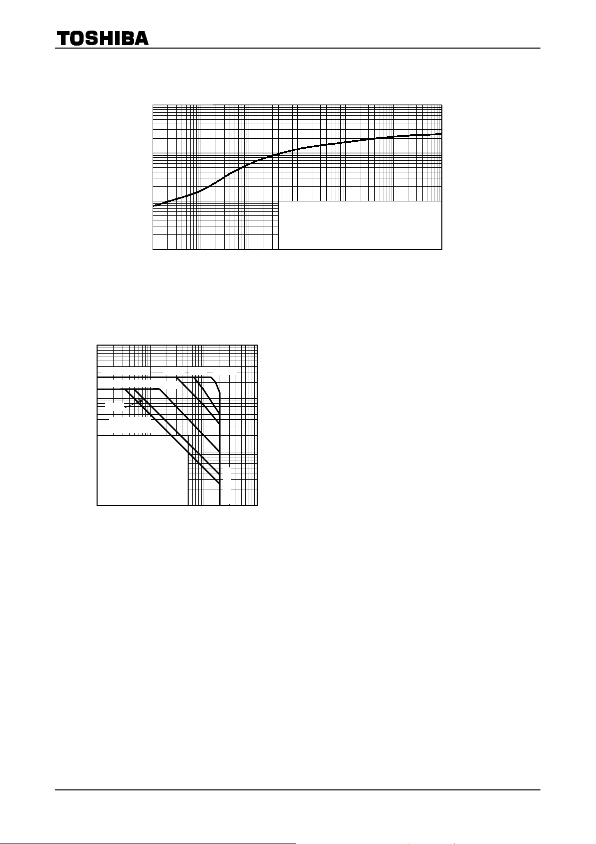
– tw
100
(°C/W)
th (j-a)
r
10
Transient thermal resistance
1
0.001 0.01 0.1 1 10 100 1000
Curves should be applied in thermal limited area.
Single nonrepetitive pulse Ta = 25°C
Mounted on FR4 board (glass epoxy, 1.6 mm thick, Cu
area: 645 mm2)
Pulse width tw (s)
−10
I
max (pulsed) ♦
C
IC max (continuous)
−1
(A)
C
Collector current I
10 s♦*
DC operation *
♦: Single nonrepetitive pulse
Ta = 25°C
−0.1
Note that the curves for 100 ms*,
10 s* and DC operation* will be
different when the devices aren’t
mounted on an FR4 board (glass
epoxy, 1.6 mm thick, Cu area:
645 mm2). These characteristic
curves must be derated linearly
with increase in temperature.
−0.01
−0.1 −1 −10 −100
Safe Operating Area
(Ta = 25°C)
Collector-emitter voltage VCE (V)
10 ms♦ 1 ms♦ 100 µs♦
100 ms♦*
max
CEO
V
4
2001-10-29
Page 5
2SA2065
A
RESTRICTIONS ON PRODUCT USE
• TOSHIBA is continually working to improve the quality and reliability of its products. Nevertheless, semiconductor
devices in general can malfunction or fail due to their inherent electrical sensitivity and vulnerability to physical
stress. It is the responsibility of the buyer, when utilizing TOSHIBA products, to comply with the standards of
safety in making a safe design for the entire system, and to avoid situations in which a malfunction or failure of
such TOSHIBA products could cause loss of human life, bodily injury or damage to property.
In developing your designs, please ensure that TOSHIBA products are used within specified operating ranges as
set forth in the most recent TOSHIBA products specifications. Also, please keep in mind the precautions and
conditions set forth in the “Handling Guide for Semiconductor Devices,” or “TOSHIBA Semiconductor Reliability
Handbook” etc..
• The TOSHIBA products listed in this document are intended for usage in general electronics applications
(computer, personal equipment, office equipment, measuring equipment, industrial robotics, domestic appliances,
etc.). These TOSHIBA products are neither intended nor warranted for usage in equipment that requires
extraordinarily high quality and/or reliability or a malfunction or failure of which may cause loss of human life or
bodily injury (“Unintended Usage”). Unintended Usage include atomic energy control instruments, airplane or
spaceship instruments, transportation instruments, traffic signal instruments, combustion control instruments,
medical instruments, all types of safety devices, etc.. Unintended Usage of TOSHIBA products listed in this
document shall be made at the customer’s own risk.
• The information contained herein is presented only as a guide for the applications of our products. No
responsibility is assumed by TOSHIBA CORPORATION for any infringements of intellectual property or other
rights of the third parties which may result from its use. No license is granted by implication or otherwise under
any intellectual property or other rights of TOSHIBA CORPORATION or others.
• The information contained herein is subject to change without notice.
000707EA
5
2001-10-29
 Loading...