

TOSHIBA
REGZ~
Owner's
Integrated
LCD
COL
Television£
0RSTRER
He
H
Manual
High
H
Definition

Dear
Thank you for purchasing this Toshiba LCD TV. This manual
will help you use the many exciting features of your new LCD
TV. Before operating yourLCD TV, please read this manual
completely, and keep it nearby for future reference.
Customer,
Child
It
MakesADifference
Safety
Safety
WARNING:
ELECTRIC SHOCK, DO NOT EXPOSE THIS APPLIANCE
TO RAIN OR MOISTURE.
WARNING:TOREDUCE
SHOCK, DO
NO
SERVICING
Precautions
TO REDUCE THE RISK OF FIRE OR
THE
RISK OF ELECTRIC
NOT
REMOVE COVER (OR BACK).
USER-5ERVICEABLE PARTS INSIDE. REFER
TO
QUALIFIED SERVICE PERSONNEL.
The lightning flash with arrowhead symbol, within
equilateral triangle, is intended to alert the user to the
presence of uninsulated "dangerous voltage" within
the product's enclosure that may be of sufficient
magnitude to constitute a risk of electric shock to
persons.
The exclamation point withinanequilateral triangle is
intended to alert the user to the presence of important
operating and maintenance (servicing) instructions
the literature accompanying the appliance.
an
in
WARNING
To prevent injury, this apparatus must be securely attached to
in
the floor/wall
See item 20 on page
WARNING:
always use a UL Listed wall bracket appropriate for the size
and weight of this television. The use of any wall bracket
other than a UL Listed wall bracket appropriate for the size
and weight ofthis television for wall mounting this television
could result
See "Removing the Pedestal Stand"
NOTETOCATV
This is a reminder to call the CATV system installer's attention
to Article 820-40 ofthe U.S. NEC, which providesguidelines for
proper grounding and,
ground shall be connected to the grounding system of the
building, as close to the point of cable entry as practical. For
additional antenna grounding information, see items 27 and 28
on
page
accordance with the installation instructions.
3.
If you decide to wall mount this television,
in
serious bodily injury and/or property damage.
(1& page 5).
INSTALLERS
in
particular, specifies that the cable
4.
Where
Congratulationsonyour
your
The
o
Your
new
TV,
TV
Stands
keep
these
purchase!Asyou
safety
tipsinmind:
enjoy
Issue
If
you are like most consumers, you have a TVinyour
home. Many homes,infact, have more than one TV.
o The hometheater entertainmentexperience is agrowing
trend, and larger TVs are popular purchases; however,
on
they are not always supported
the proper TV stands.
o Sometimes TVsare improperly secured or inappropriately
situatedondressers, bookcases, shelves, desks, audio
speakers, chests, or carts. As a result, TVs may fall over,
causing unnecessary injury.
Toshiba
Cares!
o The consumer electronics
industry is committed to
making home entertainment
enjoyable and safe.
o The Consumer Electronics
Association formed the
Home Entertainment
Support Safety Committee,
ofTVand
and
Safety
Tune
comprised
consumer electronics
furniture manufacturers, to
advocate children's safety
educate consumers and their
families about television safety.
Into
o One size does NOT fit all! Use appropriate
furniture large enough to support the weight of your TV
(and other electronic components).
a Use appropriate angle braces, straps, and anchors to
secure your furniture to the wall (but never screw
anything directly into the TV).
o Carefully read and understand the other enclosed
instructions for proper use of this product.
o
Do
not allow children to climb on or play with furniture
and TVs.
o Avoid placing any item
remote control, or toy) that a curious child may reach for.
o Remember thatchildren
and
a program
can
on
top ofyourTV (such asa VCR,
can
become excited while watching
potentially
pushorpullaTV
over.
o Share our safety message about this hidden hazard of
the home with your family and friends. Thank you!
2
.
0
'-.-&;r-\
"'-=··1\
COfl5umer
Electronics
.
Association
1919S.Eads
Arlington,VA22202
www.CE.org
Managerofthe
CEAisthe
SI
Sponsor,
U.S.A.
Producer
International
and
CES
Important
Read
1)
Keep
2)
Heed all
3)
Follow
4)
Do
5)
6)
Clean
Do
7)
accordance with the manufacturer's instructions.
Do
8)
heat registers, stoves, or other apparatus (including
amplifiers) that produce heat.
9)
Do
the
plug.
with one wider than the other.
A grounding type plug has two blades
and a third grounding prong. The wide blade
prong are provided for your safety. If the provided plug
does not fit into your outlet, consult an electrician for
replacement of the obsolete outlet.
--------
10)
Protect
on or pinched, particularly at plugs,
convenience receptacles, and the point
where they exit from the apparatus.
11)
Only
manufacturer.
12)
Use
bracket,ortable
manufacturer,orsold
apparatus.
caution when moving the cart/apparatus
combination to avoid injury from tip-over.
13)
Unplug
when
Safety
these
these
instructions.
warnings.
all
instructions.
not
use
this
only
with
not
block
not
install
not
defeat
polarizedorgrounding
A polarized plug has two blades
the
power
._----------------------
use
attachments/accessories
only
with
When a cart is used, use •
this
unused
Instructions
instructions.
apparatus
dry
cloth.
any
ventilation
near
any
the
safety
---------------
cord
the
cart,
specifiedbythe
apparatus
for
long
near
openings.
heat
sources
purpose
type
from being walked
stand,
with
the
during
periodsoftime.
water.
such as radiators,
of
Wide
specifiedbythe
tripod,
lightning
Install
in
blade
or
the third
&)
~
\.
~
~
~
~
-
storms
or
15) CAUTION:
• To reduce the risk of electric shock, do not use the
polarized plug with an extension cord, receptacle, or
other outlet unless the blades can be inserted
completely to prevent blade exposure.
• To prevent electric shock, match wide blade of plug to
wide slot; fully insert.
16) WARNING:
To
prevent the spread of fire, keep candlesorother open
flames away from this product at all times.
Installation,
Care,
and
Service
Installation
Follow these recommendations and precautions and heed all
warnings when installing your TV:
17) Never modifythis equipment. Changesormodifications
may void: a) the warranty, and
operate this equipment under the rules of the Federal
Communications Commission.
--_
_
..
_._
..
_---_._--_.---_
18)
Lh
Never place theTVon an unstable cart,
stand,
serious personal injury, death,
damage to the TV.
19) To avoid damage to this prOduct, never placeorstore the
TVindirect sunlight; hot, humid areas; orareas subjectto
excessive dust or vibration.
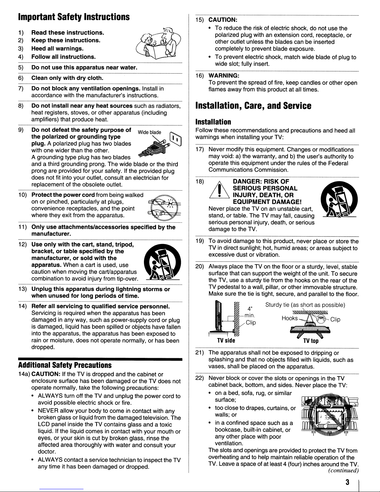
20) Always place the
surface that can support the weight ofthe unit. To secure
the TV, use a sturdy tie from the hooks on the rear of the
TV pedestal to a wall, pillar,
Make sure the tie is tight, secure, and parallel to the floor.
DANGER:
I
SERIOUS
•
INJURY,DEATH,OR
EQUIPMENT
or
table. The TV may fall, causing
RISK
PERSONAL
TV
on the floor or a sturdy, level, stable
b)
the user's authority to
..
_--_._------
OF
DAMAGE!
or
serious
or
other immovable structure.
14) Refer
Additional
14a) CAUTION: If theTVis dropped and the cabinet or
all
servicingtoqualified
Servicing is required when the apparatus has been
damaged
is damaged, liquid has been spilled or objects have fallen
into the apparatus, the apparatus has been exposed to
rain
dropped.
enclosure surface has been damaged
operate normally, take the following precautions:
• ALWAYS turn off the
avoid possible electric shock or fire.
• NEVER allow yourbody to come in contact with any
broken glass or liquid from the damaged television. The
LCD panel inside the TV contains glass and a toxic
liquid. If the liquid comes
eyes, or your skin is cut by broken glass, rinse the
affected area thoroughly with water and consult your
doctor.
• ALWAYS contact a servicetechnician to inspectthe
any time it has been damagedordropped.
in
any way, such as power-supply cord or plug
or
moisture, does not operate normally,orhas been
Safety
Precautions
TV
service
and unplug the power cord to
in
contact with your mouth
personnel.
or
theTVdoes not
or
TV
•
~
n~l:p
TV
side
21) The apparatus shall not be exposed to dripping
splashing and that no objects filled with liquids, such as
vases, shall be placed on the apparatus.
22) Never block
cabinet back, bottom, and sides. Never place the TV:
• on a bed, sofa, rug,
surface;
• too close to drapes, curtains,
walls; or
• in a confined space such as a
bookcase, built-in cabinet,
any other place with poor
ventilation.
The slotsand openings are provided to protectthe
overheating and to help maintain reliable operation of the
TV. Leave a space of atleast 4 (four) inches around the TV.
4'
SturdYtie~
HOO:S
or
cover the slots or openings in the
or
similar
or
..
o.rt~Cible)
~~CliP
TV
top
or
or
TV
TV
from
(continued)
3
23) Always place the back of the television at least four (4)
inches away from any vertical surface (such as a wall) to
allow proper ventilation.
24) Neverallow anything to reston
and neverplace theTV where the powercord is subjectto
or
wear
25) Never overload wall outlets and extension cords.
------
26) Always operate this equipment from a 120 VAC, 60 Hz
power source only.
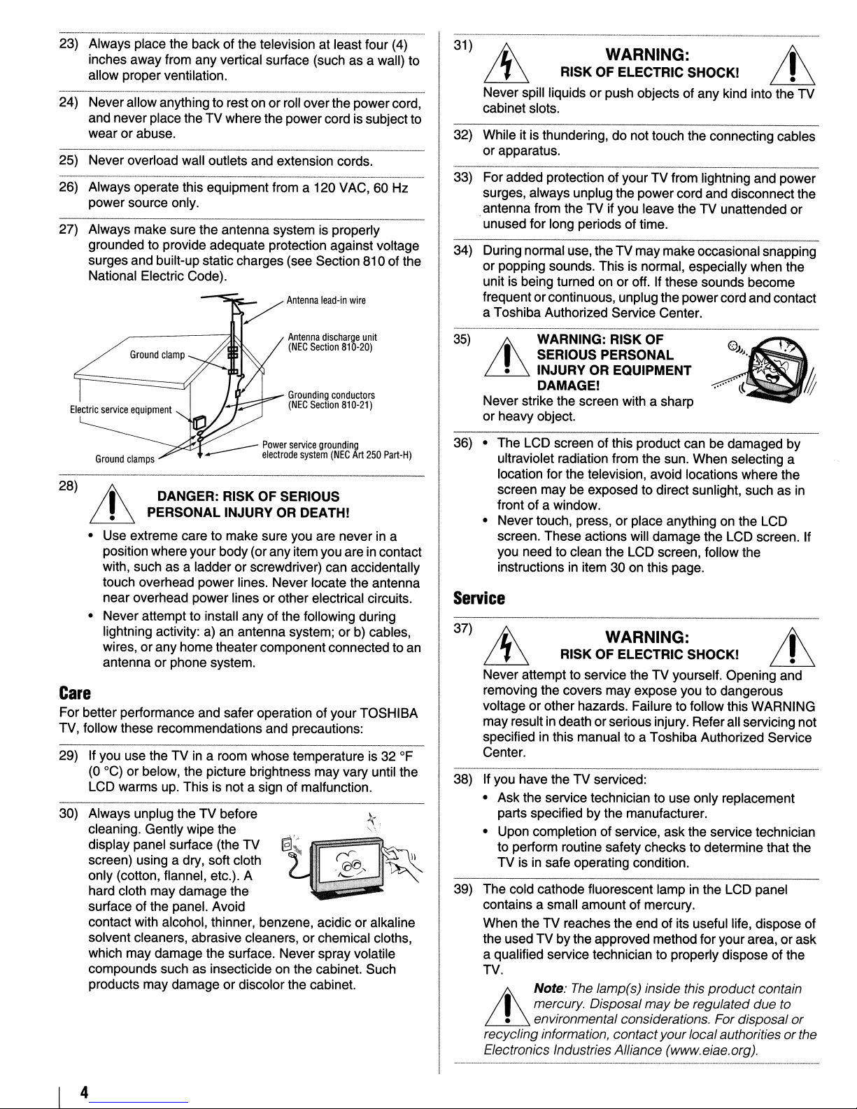
27) Always make sure the antenna system
grounded to provide adequate protection against voltage
surges and built-up staticcharges (see Section 810 of the
National Electric Code).
abuse.
or
roll overthe powercord,
is
~
Antenna
Antenna
(NEG
Section
Grounding
(NEG
Section
lead-in
discharge
properly
wire
unit
810-20)
conductors
810-21)
31
)
RISK OF ELECTRIC SHOCK!
Never spill liquids or push objects ofany kind into the TV
cabinet slots.
32) While it is thundering, do not touch the connecting cables
or apparatus.
33) For added protection ofyour TV from lightning and power
surges, always unplug the power cord and disconnect the
antenna from the TV
.unused for long periods of time.
34) During normal use, theTV may makeoccasionalsnapping
or popping sounds. This is normal, especially when the
unit is being turned on or off. If these sounds become
frequent orcontinuous, unplug thepower cord and contact
a Toshiba Authorized Service Center.
35)
WARNING: RISK OF
WARNING:
if
you leave the TV unattended
Lh
or
I SERIOUS PERSONAL
• INJURY OR EQUIPMENT
Lh
Never strike the screen with a sharp
or heavy object.
DAMAGE!
___
Power
service
----
28)
t
~
• Use extreme care to make sure you are never in a
position where your body(orany item you are in contact
with, such as a ladder
touch overhead power lines. Never locate the antenna
near overhead power lines
• Never attempt to install any of the following during
lightning activity: a) an antenna system; or b) cables,
wires, or any home theater component connected to an
antenna
DANGER: RISK OF SERIOUS
PERSONAL INJURY OR DEATH!
or
phone system.
electrode
or
screwdriver) can accidentally
or
grounding
system
(NEG
Art
250
Part-H)
other electrical circuits.
Care
For better performance and safer operation of yourTOSHIBA
TV, follow these recommendations and precautions:
29) If you use the TV
(0
°C)orbelow, the picture brightness may vary until the
LCD warms up. This is not a sign of malfunction.
30) Always unplug the TV before
cleaning. Gently wipe the
display panel surface (the TV
screen) using a dry, soft cloth
only (cotton, flannel, etc.). A
hard cloth may damage the
surface of the panel. Avoid
contact with alcohol, thinner, benzene, acidic
solvent cleaners, abrasive cleaners, or chemical cloths,
which may damage the surface. Never spray volatile
compounds such as insecticide on the cabinet. Such
products may damage or discolor the cabinet.
in
a room whose temperatureis32
or
OF
k.
'"
alkaline
36) • The LCD screen of this product can be damaged by
ultraviolet radiation from the sun. When selecting a
location for the television, avoid locations where the
screen may be exposed to direct sunlight, such as in
front of a window.
or
• Never touch, press,
screen. These actions will damage the LCD screen. If
you need to clean the LCD screen, follow the
instructions in item 30
place anything on the LCD
on
this page.
Service
37)
RISK OF ELECTRIC SHOCK!
Never attemptto service the TV yourself. Opening and
removing the covers may expose you to dangerous
or
voltage
may result
specified
Center.
38) If you have the TV serviced:
• Ask the service technician to use only replacement
parts specified by the manufacturer.
• Upon completion of service, ask the service technician
to perform routine safety checks to determine that the
TV is in safe operating condition.
39) The cold cathode fluorescent lamp in the LCD panel
contains a small amount of mercury.
When the TV reaches the end of its useful life, dispose of
the used
a qualified service technician to properly dispose of the
TV.
other hazards. Failure to follow this WARNING
in
death orseriousinjury. Refer all servicing not
in
this manual to a Toshiba Authorized Service
TV
by the approved method for your area, orask
Note:
I mercury. Disposal may
• environmental considerations. For disposal
Lh
recycling information, contactyour localauthoritiesorthe
Electronics Industries Alliance (www.eiae.org).
WARNING:
The
lamp(s) inside this product contain
be
regulated due to
or
4
Choosingalocation
To
Display
your
LCDTVon
for
the
your
LCD
included
TV
Pedestal
Stand:
Observe the following safety precautions:
I) Read and Follow the pedestal assembly instructions included
with the pedestal.
CAUTION: Before beginning pede:stal assembly, carefullylay
the front
surface such as a quilt or blanket. Leave the bottom
protruding over the edge
pedestal as indicated below.
Note: Extreme care should always
the pedestal stand to avoid damage to the LCD panel.
2) Place the TV on a sturdy, level surface that can support the
weight
3) Be sure to secure the TV to a wall, pillar, surface, or other
immovable structure. To secure the TV in this manner, use the
included strap locatedat the rear
page 3).
To
Display
If you decide to wall mount your LCD TV, always use a ULlisted wall bracket appropriate for the size and weight of the
LCD TV
1)
CAUTION: Two people are required for installation.
2) Unplug and remove any cables and/or other component
connectors from the rear
3) Follow the instructions provided with your wall bracket.
Before proceeding, make sure the appropriate bracket(s) are
attached to the wall and the back
instructions provided with the wall bracket.
4) After attaching the appropriate bracket(s) to the wall and the
back
described below.
of
the LCD Panel face downona flat, cushioned
of
the surface and assemble the
be
used when attaching
of
the TV.
of
pedestal stand.
your
LCDTVusingaWall
(Q'
page 2) :
of
the TV.
of
the TV as described in the
of
the TV, remove the pedestal stand from the TV as
(W
Bracket:
of
the unit
item 20,
Removing
1) Carefully lay the front
cushioned surface such as a quilt or blanket. Leave the stand
protruding over the edge
Note: Extreme care shouldalways beused when removing
the pedestal stand to avoid damage
2) Remove the jack pack cover on the backofthe TV to expose
the pedestal stand screws. The jack pack covercan be removed
without tools.
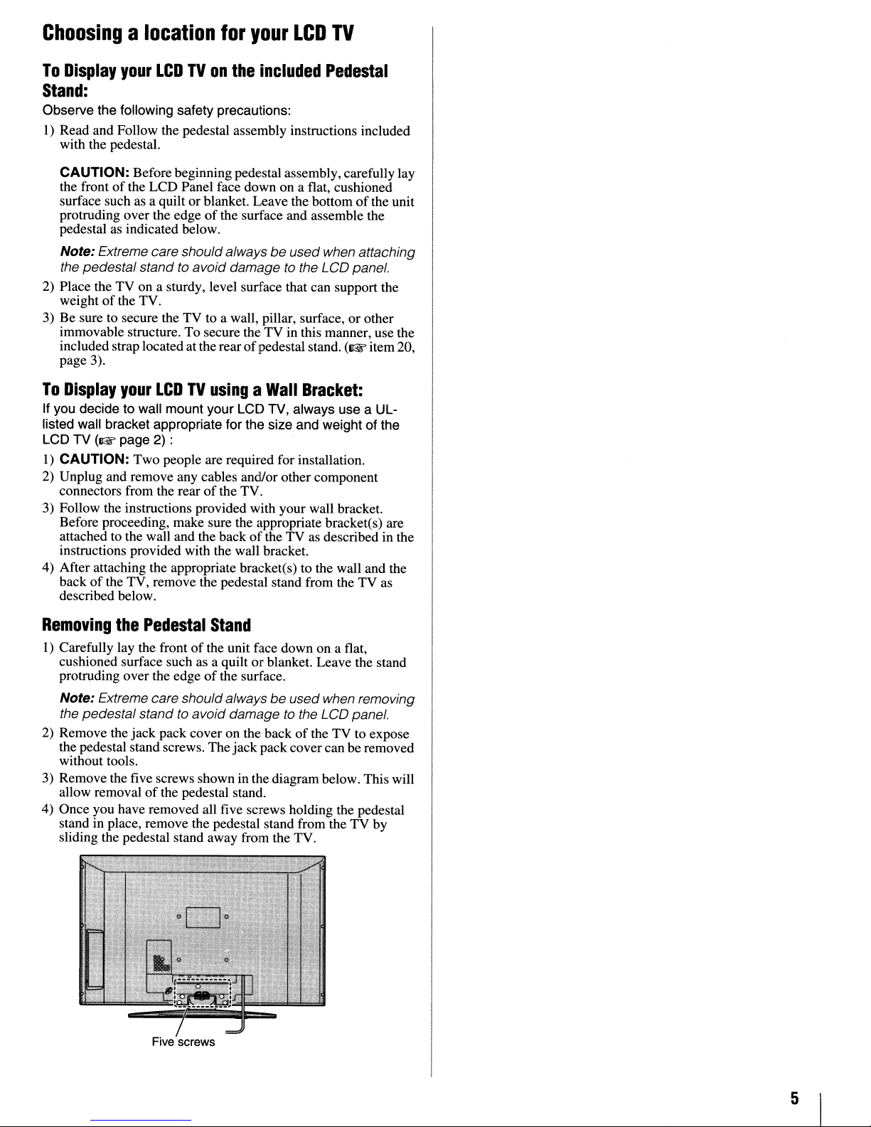
3) Remove the five screws shown in the diagram below. This will
allow removal
4) Once you have removed all five screws holding the pedestal
stand in place, remove the pedestal stand from the TV by
sliding the pedestal stand away from the TV.
the
Pedestal
of
the pedestal stand.
Stand
of
the unit face down on a flat,
of
the surface.
to
the LCD panel.
Five screws
5
FCC
DeclarationofConformity
Important
notes
about
your
LCD
Compliance
(Part
The Toshiba 26HL47, 26HL67, 32HL67US, 32HL67,
32HL67U, 37HL67S, 37HL67, 42HL67US, and 42HL67
Televisions
Operationissubject to the following two conditions: (1) this
device may not cause harmful interference, and (2) this device
must accept any interference received, including interference that
may cause undesired operation.
The party responsible for compliance to these rules is:
Toshiba AmericaConsumer Products,
82 Totowa Rd. Wayne, NJ 07470.
Ph: 1-800-631-3811
Note:
with the limits for a Class B digital device, pursuant to Part
of
the FCC rules. These limits are designedtoprovide
reasonable protection against harmful interference
residential installation.
can radiate radio frequency energyand,ifnot installed
usedinaccordance with the instructions,
interference
no guarantee that interference will not
installation. Ifthis equipment does cause harmful interference
to
radioortelevision reception, which can be determined
removing
encouragedtotrytocorrectthe interferencebyoneormore
the following measures:
• Reorient or relocate the receiving antenna.
• Increase the separation between the equipment and the
receiver.
• Connect the equipment into an outlet on a circuit different
from that
• Consult the dealer or an experienced radioffV technician for
help.
Caution:
expresslyapproved
to
operate this equipment.
15):
comply with Part15of
This
equipment has been tested
to
radio communications. However, there
and
applying
to
which the receiverisconnected.
Changesormodificationstothis equipment not
Statement
the FCC rules.
L.L.c.
and
foundtocomply
This
equipment generates, uses,
may
cause harmful
occurina particular
powertothe equipment, the user
by
Toshiba
could
void the user's authority
15
in
a
and
and
is
by
is
TV
The
following
Display technology
therefore,
resulting
\)
An afterimage (ghost) may appearon the screenifa fixed, nonmoving image is displayed for a long period
afterimageis not permanent and willdisappearin a short period
of
time.
2) The LCD panel contained in this TV
extremely high level
may be an occasional pixel (dot
properly (does not light, remains constantly lit, etc.). This
structural property
malfunction, and is not covered under your warranty. Such
pixels are not visible when the pictureis viewed from a normal
viewing distance.
Note: Interactive video games that involve shooting a "gun"
type
of
TV.
Trademark
•
wow,
of
WOW technology
• Manufactured under license from Dolby Laboratories.
Dolby and the double-D symbol are registered trademarks of Dolby
Laboratories.
• HDMI, the HDMI logo and High-Definition Multimedia Interface are
trademarks or registered trademarks of HDMI Licensing LLC.
symptoms
and
Toshibaisnot
from
these symptoms.
of
joystickatan on-screen target maynot work with this
SRS
and ce) symbol are trademarks of
is
incorporated under license from
are
technical limitationsofLCD
are
notanindicationofmalfunction;
responsible
of
precision technology; however, there
LCD technology,isnot a sign
for
perceived issues
of
time. The
is
manufactured using an
of
light) that does not operate
Information
SRS
Labs, Inc.
SRS
is
of
Labs, Inc.
a
6
Contents
Important
Installation,
Safety
Care,
Instructions
and
Service
Chapter1:Introduction
Welcome to Toshiba 8
Features
Overview
TV front and side panel controls and connections 10
TV back panel connections
Chapter2:Connecting
Overviewofcable types
About the connection illustrations
Connecting a VCR and antenna or Cable TV
Connecting a VCR with S-video and a cable box
Connecting a DVD player with ColorStream®
Connecting a camcorder 16
Connecting an HDMI'" or DVI device to the HOMI
Connecting a digital audio system
Connecting an audio system
Connecting a personal computer (PC)
Chapter3:Using
Preparing the remote control for use 20
Installing the remote control batteries 20
Remote control effective range 20
Learning about the remote control
Using the remote control to control your other devices 22
Remote Control functional key chart 23
Programming the remote control to control your other
Remote control codes
Chapter4:Menu
Main menu layout 27
SetuplInstallation menu layout 28
Navigating the menu system 28
of
your new TV 8
of
steps for installing, setting up, and using
your new TV 9
your
(no Cable box)
(component video), a VCR, and a satellite receiver.
input
the
remote
devices 24
layout
Chapter5:Settingupyour
Selecting the menu language 29
Configuring the antenna input source for the ANT
terminal 29
Programming channels into the
Programming channels automatically 30
Manually adding and deleting channelsinthe channel
memory 30
Labeling channels
Setting the HDMI
Viewing the digital signal meter. 33
Viewing the system status 33
Selecting the Power-On Mode 34
Chapter6:Using
Selecting the video input source to view 35
Labeling the video input sources
Tuning channels 36
Selecting the picture size 39
the
TV's
Tuning channels using the Channel Browser™ 36
Tuning to the next programmed channel 38
Tuning to a specific channel (programmed or
unprogrammed) 38
Switching between two channels using Channel
Return 38
Switching between two channels using SurfLock
. . . . . . . . . . . . . . . . . . . . . . . . . ...8
II
TV
control
and
navigation
TV
TV's
channel memory 30
T
audio mode 32
"
features
12
12
12
13
14
15
17
18
18
19
20
21
25
27
29
31
35
35
T
"
••••
38
3
3
Scrolling the TheaterWide® picture
(TheaterWide 2 and 3 only) 40
Using the auto aspect ratio feature
Selecting the cinemamode (480i and 1080i signals)
Adjusting the picture 42
Selecting the picture mode 42
Adjusting the picture quality 42
Using the closed caption mode 43
Base closed captions 43
Digital CC Settings 43
CC Selector 44
Adjusting the audio 44
Muting the sound 44
Using the digital audio selector 44
Selecting stereo/SAP broadcasts 45
Adjusting the audio quality 45
Using the StableSound® feature 46
Selecting the optical audio output format 46
Using the Dolby® Digital Dynamic Range
Control feature 46
Using the Locks menu 47
Entering the PIN code 47
If
you cannot remember your PIN code 47
Changing your PIN code 47
Blocking TV programs and movies by rating
(V-Chip) 48
Downloading an additional rating system for blocking
TV programs and movies 48
Blocking channels 49
Unlocking programs temporarily 50
Using the input lock feature 50
Using the control panel lock feature
Using the PC settings feature
Setting the PC Audio 52
Setting the sleep timer. 52
Displaying TV status information 53
Understanding the auto power off feature 53
Understanding the last mode memory feature 53
Chapter7:Using
Using the advanced picture settings features 54
Using the HDMI settings feature (only for models 26HL47,
Using the advanced audio settings features 57
the
TV's
advanced
Using dynamic contrast 54
Using the static gamma feature 54
Selecting the color temperature 55
Using CableClear® digital noise reduction 55
Using MPEG noise reduction 56
Using the Game Mode feature 56
32HL67US, 37HL67S, and 42HL67US) 57
Using the SRS WOW
features
T
surround sound feature 57
"
Chapter8:Troubleshooting
General troubleshooting 58
LED indications 60
Chapter9:Appendix
Specifications
Limited United States Warranty
for LCD Televisions 26" and Larger 63
Limited Canadian Warranty
for Toshiba Brand Flat Panel Televisions 64
Index
41
41
51
51
54
58
61
61
67
7
WelcometoToshiba
Featuresofyour
new
TV
Thank you for purchasing this Toshiba LCD TV, oneofthe
most innovative LCD TVs on the market. This digital
television is capableofreceiving analog basic, digital basic
and digital premiumcable television programming by direct
connection to a cable system providing such programming. A
security card provided by your cable operator is required to
view encrypted digital programming. Certain advanced and
interactive digital cable services such as video-on-demand, a
cable operator's enhanced program guide and data-enhanced
television services may require the useofa set-top box. For
more information call your local cable operator.
The following are just a fewofthe many exciting features
your new Toshiba widescreen, integrated HD, LCD TV:
•
Integrated
eliminates the need for a separate digital converter set-top
box (in most cases).
•
Three
interfaces 1080p input support (1& page 17).
•
Two
video inputs (1& page 15).
• SRS WOW™ audio technologies (1& page 57).
• Digital Audio
Digital optical output format (1& page 46).
• CableClear® digital picture noise reduction
(1& page 55).
•
PCIN(Analog
•
Channel
ABC, HBO, etc.) on the screen along with the station
numbers, so you always know what you're watching
(1& page 31).
digital
HDMr'"
setsofColorStream®HDhigh-resolution component
Labeling
tuning
digital, high-definition multimedia
Out
RGB)
(8VSB A
optical audio connection with Dolby®
computer terminal (1& page 19).
allows you to put the Call Letters (e.g.
TSC
and
QAM)
of
8
Overviewofsteps
setting
Follow these steps to set up your TV and begin using its many
exciting features.
up,
and
for
using
installing,
your
new
TV
1 Carefully read the important safety, installation, care, and
service information. Keep this manual for future
reference.
2 Observe the following when choosing a location for the
TV:
• Read "Important notes about your LCD TV"
(lIE
page 6).
• Place the TV on the floor or a sturdy, level, stable
surface that can support the weight
the TV to a wall, pillar, or other immovable structure
(lIE
page 3).
• Place the TV in a location where light does not reflect
on the screen.
• Place the TV farenough from walls andother objects
allow proper ventilation. Inadequate ventilation may
cause overheating, which will damage the TV. THIS
TYPE OF DAMAGE IS NOT COVERED UNDER
THE TOSHIBA WARRANTY.
of
the unit. Secure
3 Do not plug in any power cords until AFTER you have
connected all cables and devices to your TV.
4 BEFORE connecting cables ordevices to the TV, learn
of
the
TV's
the functions
(~pages
10-1l).
connections and controls
5 Connect your other electronic device(s) to the TV
(~pages
6 Install the batteries in the remote control
7 See "Learningabout the remote control"
an overview
12-19).
of
the buttons on the remote control.
(~
(~
page 21) for
page 20).
8 Program the remote control to operate your other
device(s)
(~
pages 22-26).
9 AFTER connecting all cables and devices, plug in the
power cords for your TV and other devices. The yellow
LED will blink until the TV goes into standby mode.
When the TV is in standby mode, press
TV
control panel or remote control to tum on the TV.
If
the TV stops responding to the controls on the remote
control or TV control panel and you cannot tum the TV
off
or on, press and hold the POWER button for 5
seconds to reset the TV.
POWER on the
10 See "Menu layoutand navigation"for a quickoverview
navigating the
11
Program channels into the
(~page
12For details on using the
7.
and
13For help, refer to the Troubleshooting Guide, Chapter
30).
TV's
menu system
TV's
TV's
features, see Chapters 6
(~page
channel memory
27).
of
8.
14For technical specifications and warranty information, see
Chapter
9.
15Enjoy your new TV!
to
9
TV
front
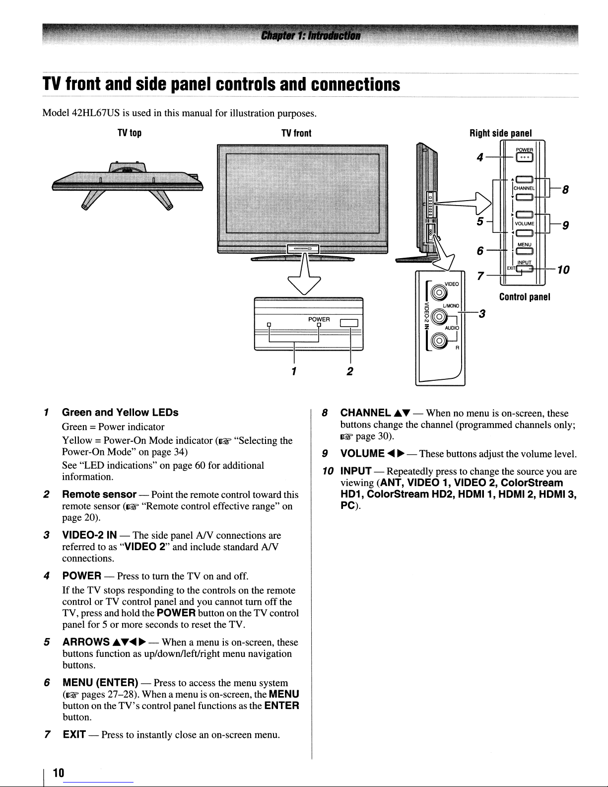
Model 42HL67US is used in this manual for illustration purposes.
and
TV
top
side
panel
controls
and
TV
front
connections
Right
side
Control
panel
POWER
B
..
CJl
ICHANNEL
~C::J
!C)
IVOLUME
<c:J
IMENU
'c:J
I
INPUT
EXIT
8
9
10
panel
1 Green and Yellow LEOs
Green =Power indicator
Yellow =Power-On Mode indicator
Power-On Mode" on page 34)
See "LED indications" on page 60 for additional
information.
2 Remote sensor- Point the remote control toward this
remote sensor
page 20).
3 VIDEO-2IN- The side panel
referred to as "VIDEO 2" and include standard
connections.
4
POWER
If
theTVstops responding to the controls on the remote
controlorTV control panel and you cannot
TV, press and holdthe
panel for 5 or more seconds to reset the TV.
5 ARROWS ~...
buttons function as up/down/leftJright menu navigation
buttons.
(~
"Remote control effective range" on
- Press to tum the TV on and off.
POWER
~ ~
- When a menu is on-screen, these
(~
"Selecting the
NY
connections are
NY
tum
off
the
button on theTVcontrol
1
2
8 CHANNEL
buttons change the channel (programmed channels only;
~page
9 VOLUME
10
INPUT- Repeatedly press to change the source you are
viewing (ANT, VIDEO 1, VIDEO
HD1,
PC).
~
... - When no menu is on-screen, these
30).
~
~
- Thesebuttons adjustthe volume level.
2,
ColorStream
ColorStream HD2, HDMI1, HDMI2,
HDMI
3,
6
MENU
(~
button on the
button.
7 EXIT - Press to instantly close an on-screen menu.
I
10
(ENTER) - Press to access the menu system
pages 27-28). When a menu is on-screen, the
TV's
control panel functions as the
MENU
ENTER
---------_._------------_._--_._---
TV
back
panel
_ - _
connections
.._..
_
_-
................•......
_.....
.-_.-
_ _ .
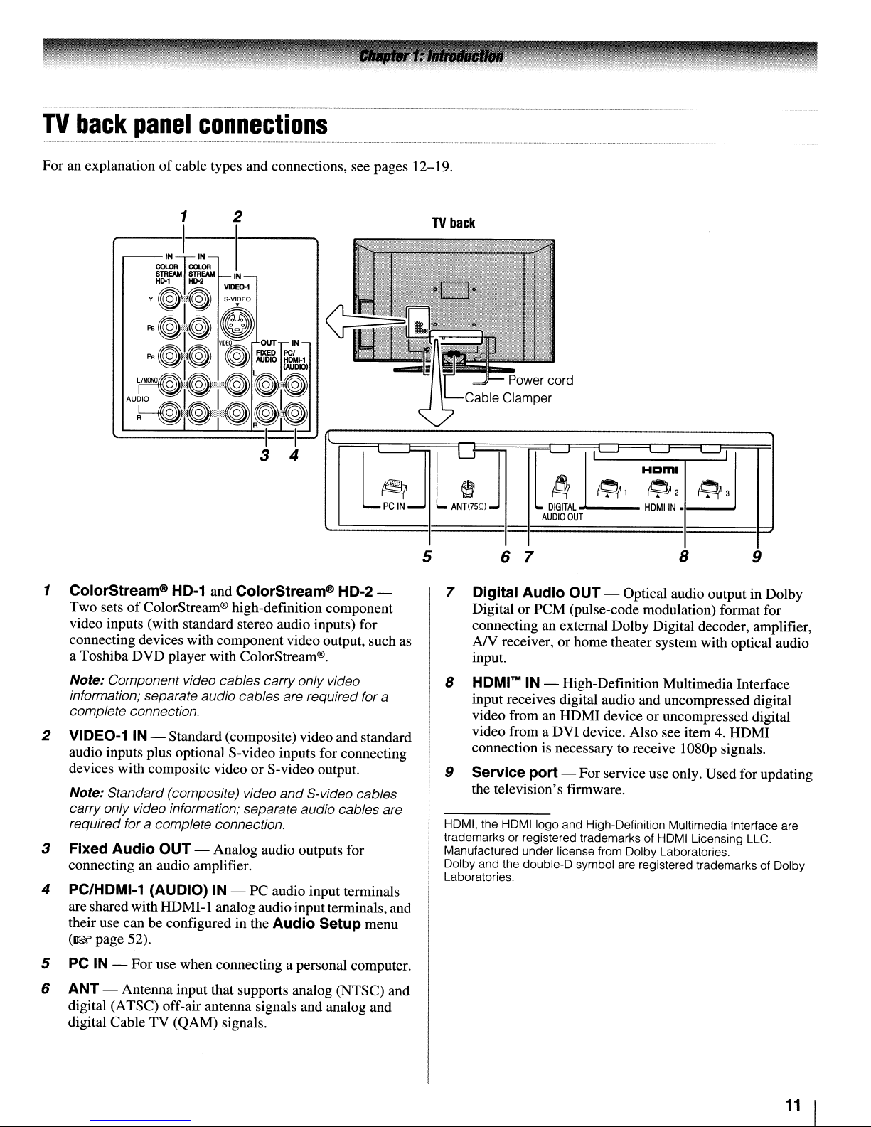
For an explanationofcable types and connections, see pages 12-19.
1 2
1 ColorStream® HD-1 and ColorStream® HD-2 -
Two setsofColorStream® high-definition component
video inputs (with standard stereo audio inputs) for
connecting devices with component video output, such as
a Toshiba DVD player with ColorStream®.
Note: Component video cables carry onlyvideo
information; separate audio cables are required for
complete connection.
2 VIDEO-1 IN - Standard (composite) video and standard
audio inputs plus optional S-video inputs for connecting
devices with composite video or S-video output.
Note: Standard (composite) video
carry only video information; separate audio cables are
required for
a complete connection.
and
S-video cables
3 Fixed Audio OUT - Analog audio outputs for
an
connecting
audio amplifier.
4 PC/HDMI-1 (AUDIO) IN - PC audio input terminals
are shared with HDMI-l analog audio inputterminals, and
their use can be configured in the
(1&
page 52).
Audio Setup menu
a
TV
back
5 6 7
8 9
7 Digital Audio OUT - Optical audio output in Dolby
Digital
connecting
AJV receiver, or home theater system with optical audio
or
PCM (pulse-code modulation) format for
an
external Dolby Digital decoder, amplifier,
input.
8
HDMI™
IN - High-Definition Multimedia Interface
input receives digital audio and uncompressed digital
video from an HDMI device or uncompressed digital
video from a DVI device. Also see item 4. HDMI
connection is necessary to receive 1080p signals.
9 Service port - Forservice use only. Used for updating
the television's firmware.
HDMI, the HDMIIogo and High-Definition Multimedia Interface are
trademarks or registered trademarks of HDMI Licensing LLC.
Manufactured under license from Dolby Laboratories.
Dolby and the double-D symbol are registered trademarks of Dolby
Laboratories.
5 PC IN - For use when connecting a personal computer.
6 ANT - Antenna input that supports analog (NTSC) and
digital (ATSC) off-air antenna signals and analog and
digital Cable TV (QAM) signals.
11
I
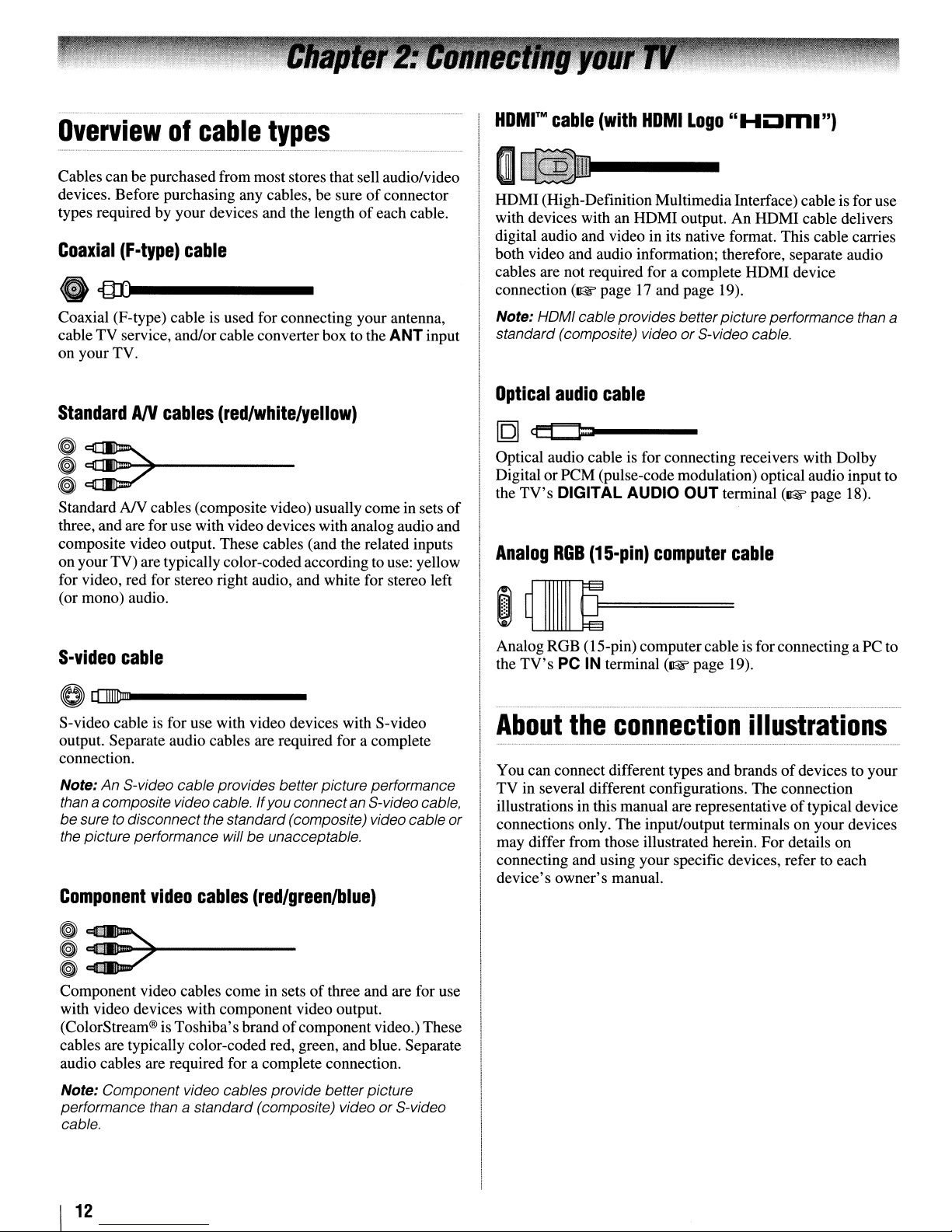
Overviewofcable
Cables can be purchasedfrom most stores that sell audio/video
devices. Before purchasing any cables, be sureofconnector
types required by your devices and the lengthofeach cable.
Coaxial
ecIDl
Coaxial (F-type) cable is used for connecting your antenna,
cable TV service, and/or cable converter box to the ANTinput
on your TV.
(F-type)
...
----
cable
types
M
HOMr
HDMI (High-DefinitionMultimedia Interface) cableis for use
with devices with an HDMI output. An HDMI cable delivers
digital audio and video in its native format. This cable carries
both video and audio information; therefore, separate audio
cables are not required for a complete HDMI device
connection
Note: HOMI cable provides betterpicture performance than a
standard (composite) videoorS-video cable.
cable
(~
(with
HOM
I
Logo"
page17and page 19).
HOm.")
StandardANcables
(red/white/yellow)
I~~---
~~
Standard
three, and arefor usewith videodevices with analog audio and
composite video output. These cables (and the related inputs
on your TV) are typically color-codedaccording to use: yellow
for video, red for stereo right audio, and white for stereo left
(or mono) audio.
S-video
NY
cables (composite video) usually comein sets
cable
of
o[[II]IDm-----
S-video cable is for use with video devices with S-video
output. Separate audio cables are required for a complete
connection.
Note:
An
S-video cable provides better picture performance
than
a composite video cable. If you connect an S-videocable,
be
suretodisconnect the standard (composite) video cable
the picture performance will be unacceptable.
Component
video
cables
(red/greenlblue)
Optical
[Q]
Optical audio cable is for connecting receivers with Dolby
DigitalorPCM (pulse-code modulation) optical audio input to
the
Analog
audio
cable
ct:t::J=1
TV's
DIGITAL AUDIO OUT terminal
ROB
(1S-pin)
computer
(~page
cable
~~=
~~
Analog RGB (15-pin) computer cable is for connecting a PC to
the
TV's
or
PC IN terminal
About
You can connect different types and brandsofdevices to your
TV
illustrations in this manual are representativeoftypical device
connections only. The input/output terminals on yourdevices
may differ from those illustrated herein. For details on
connecting and using your specific devices, refer to each
device's owner's manual.
the
connection
in several different configurations. The connection
(~page
19).
illustrations
18).
~
._~-----
~::7
~
Component video cables come in setsofthree and are for use
with video devices with component video output.
(ColorStream® is Toshiba's brandofcomponent video.) These
cables are typically color-coded red, green, and blue. Separate
audio cables are required for a complete connection.
Note: Component video cables provide better picture
performance than
cable.
I
12
a standard (composite) video
or
S-video
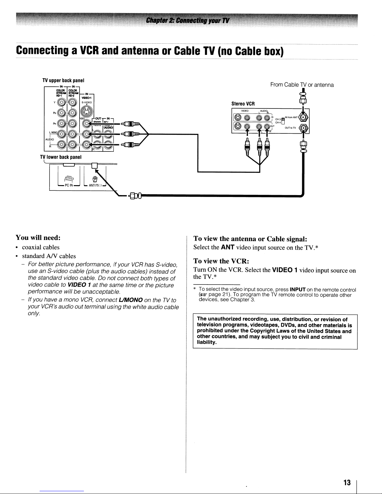
ConnectingaVCR
TV
lower
•••••••••••••••••••••••••••••••••••••••
back
_
panel
and
_..•••_•••
antennaorCable
_ M~•••••••••••
_...........
TV
(no
•
••••••
_._
Cable
••••••••••••••_••
box)
_ _
••••••••••_•••••••••••••••••••••••••••••••••••_•••••_•••_••••••••••~•••••••••••••••••_••••••
_ _
••••••
_ _
~Jl
L
PC
IN
~
ANH7SCj
You will need:
• coaxial cables
AN
• standard
For betterpicture performance,ifyour
use an S-video cable (plus the audio cables) instead
the standard video cable. Do not connect both types
video cable
performance will
-
If
you have a mono
your VCR's audiooutterminal using the white audio cable
only.
cables
to
VIDEO 1
at
be
unacceptable.
VCR,
connect
VCR
has S-video,
the same timeorthe picture
UMaNa
on theTVto
of
of
To view the antenna or Cable signal:
Select the
ANT
video input source on the TV.*
To view the VCR:
Tum
ON the VCR. Select the
the TV.*
*
To
select the video input source, press INPUTonthe remote control
(~page
devices, see Chapter
The unauthorized recording, use, distribution, or revision of
television programs, videotapes, DVDs, and other materials is
prohibited under the Copyright Laws of the United States and
other countries, and may subject you to civil and criminal
liability.
21).Toprogram theTVremote control to operate other
3.
VIDEO
1 video input source on
13
I
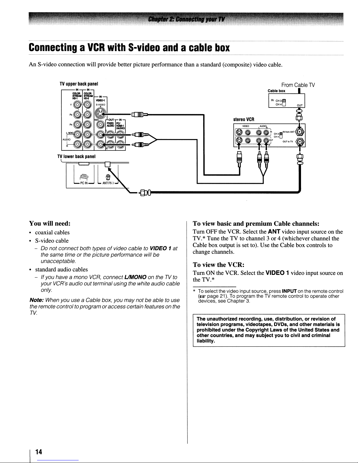
ConnectingaVCR
An S-video connection will provide better picture performance than a standard (composite) video cable.
TV
lower
back
panel
with
S-video
andacable
box
~Jl
l
PC
IN
~
ANTI750l
You will need:
• coaxial cables
• S-video cable
- Do not connect both types
the same timeorthe picture performance will
unacceptable.
• standard audio cables
- Ifyou havea mono
your VCR's audio out terminal usingthe white audio cable
only.
Note: When you use a Cable box, you
the remotecontrolto
TV.
VCR,
programoraccesscertain features onthe
of
video cable to VIDEO 1
connect UMONO on theTVto
may
notbeable to use
be
at
To view basic and premium Cable channels:
Tum
OFF the VCR. Select the ANT video input source on the
TV.* Tune the TV to channel 3or4 (whichever channel the
Cable box output is set to). Use the Cable box controls to
change channels.
To view the VCR:
Tum
ON the VCR. Selectthe VIDEO 1 video inputsource on
the TV.*
*
To
select the video input source, press INPUT on the remote control
(~page
devices, see Chapter
The unauthorized recording, use, distribution, or revision of
television programs, videotapes, DVDs, and other materials is
prohibited underthe Copyright Laws of the United States and
other countries, and may sUbject youtocivil and criminal
liability.
21).Toprogram theTVremote controltooperate other
3.
1
14
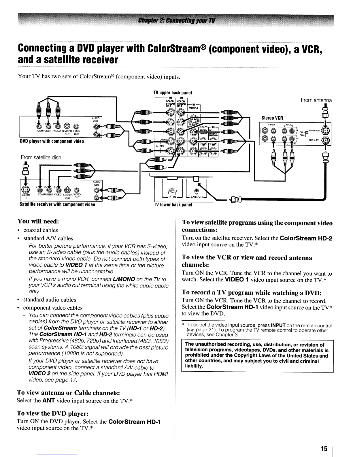
ConnectingaDVD
player
with
ColorStream®
(component
video),aVCR,
andasatellite
Your TV has two setsofColorStream® (component video) inputs.
receiver
lfi~
~-,-,
'.
p,.", 0
COMPONENT
VIDEO
DVD
player
with
component
From
satellite
~
Satellite
r----
receiver
dish
with
You will need:
• coaxial cables
• standard
- For better picture performance,ifyour
- Ifyou have a mono
• standard audio cables
• component video cables
-
- Ifyour
AN
use an S-video cable (plus the audio cables) instead
the standard video cable.00notconnect both types
video cable
performance willbeunacceptable.
your VCR's audioout terminal using the white audio cable
only.
You
can connect thecomponent videocables (plusaudio
cables) from the
set
of
ColorStream terminals on theTV(HD-1
The
ColorStream HD·1
with Progressive
scan systems. A
performance
OVO
component video, connect a standard
VIDEO 2 on the side panel. Ifyour
video, see
~
S-VIOEQ
VIDEO
OUT OUT
video
3E>O-+-----I-.=!!!:!:::~--------.J
component
cables
to
VIDEO 1
OVO
(4BOp,
1OBOi
(1OBOp
playerorsatellite receiver does not have
page
17.
AUDIO
i'"-'.-..-.-n-.
,$
~
AUDIO
OUT
~.c:lI:m=:D\..
~
video
VCR
has S-video,
at
the same time or the picture
VCR,
connect
playerorsatellite receivertoeither
and
720p)
signal will provide the
is not supported).
UMaNa
HD-2 terminals can
and
Interlaced
OVO
on theTVto
(4BOi,
best
AN
cable
player has
or
be
HD-2).
picture
to
l
TV
lower
of
of
used
10BOi)
HoMI
re-rJ
PC
IN
back
From
antenna
Stereo
l
~,I
VIDEO
Ie
~•~
~,
VCR
A'""9,
,_,.+OH'
t
CH'l:f-
~
-J,~=-
ANT
<@
OUT10TV
,
ANT<!5r.1~
panel
To viewsatellite programsusingthe componentvideo
connections:
Tum
on the satellite receiver. Select the ColorStream HD-2
video input source on the TV.*
To view the VCR or view and record antenna
channels:
Tum
ON the VCR. Tune the VCR to the channel you want to
watch. Select the
To record a TV program while watching a DVD:
Turn ON the VCR. Tune the VCR to the channel to record.
Selectthe
to view the DVD.
*
To
(1& page 21).
devices, see Chapter
The unauthorized recording, use, distribution, or revision of
television programs, videotapes, DVDs, and other materials is
prohibited under the Copyright Laws of the United States and
other countries, and may subject you to civil and criminal
liability.
ColorStream HD-1 video inputsource on the TV*
select the video input source, press INPUT on the remote control
VIDEO 1 video input source on the TV.*
To
program theTVremote control to operate other
3.
To view antenna or Cable channels:
Select the
ANT
video input source on the TV.*
To view the DVD player:
Turn ON the DVD player. Select the ColorStream HD-1
video input source on the TV.*
15
I
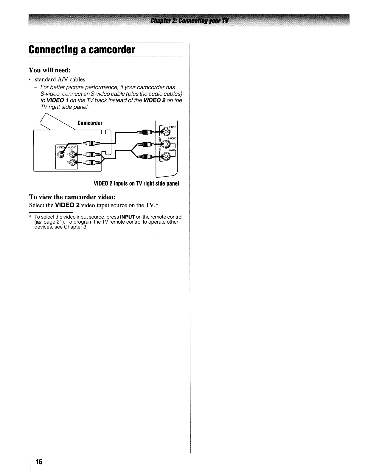
Connectingacamcorder
You will need:
• standard AIV cables
- For betterpicture performance,ifyour camcorderhas
S-video, connectan S-videocable (plus the audio cables)
to
VIDEO 1on theTVback
TV
right side panel.
Camcorder
insteadofthe VIDEO 2 on the
VIDEO2inputsonTV
right
To view the camcorder video:
Select the VIDEO 2 video input source on the TV.*
*
To
select the video inputsource, press INPUTonthe remote control
(~page
devices, see Chapter
21).Toprogram theTVremote controltooperate other
3.
side
panel
16
1
Connecting
to
the
HDMI
an
HDMI™orDVI
input
device
The HDMI input on your TV receives digital audio and
uncompressed digital video from an HDMI source device, or
uncompressed digital video from a DVI (Digital Visual
Interface) source device.
This input
Digital-Content Protection) program material
is
designed to accept HDCP (High-Bandwidth
in
digital form
from EINCEA-861-D-compliant[11 consumer electronic
devices (such as a set-top box or DVD player with HDMI or
DVI output).
The HDMI input can accept and display VGA, 480i (60Hz),
4801' (60Hz),
nop (60Hz), 1080i (60Hz), and 10801' (24Hz/
60Hz) signal formats. For detailed signal specifications, see
page 62.
Supported Audio format: Linear PCM, sampling rate 32/44.11
48kHz
Note:
To
connecta PCtothe HOMI input, see
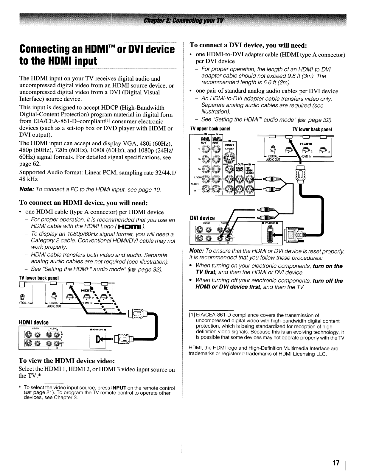
To
connectanHDMI
device, you will need:
page
19.
• one HDMI cable (type A connector) per HDMI device
- For
proper
HOMI cable with the HOMI Logo
-
To
display an 1080p/60Hz signal format, you will need a
Category2 cable. Conventional HOMI/OVI cable may not
work properly.
- HOMI cable transfers both video
analog audio cables are not required (see illustration).
- See "Setting the HOM!"" audio
TV
lower
back
o J
~
~T(75(;)
HDMI
device
operation, itisrecommended thatyou use an
(HLJml).
and
audio. Separate
mode"
panel
lLJ~C:j
~~,
DIGITAL
AUDIO
OUT
H:;~
~2·.~~~
HDMIIN
__
~I
~.-
••_••
(1&
page
••
32).
To
connect a DVI device, you will need:
• one HDMI-to-DVI adaptercable (HDMI type A connector)
per DVI device
- For proper operation, the lengthofan HOMI-to-OVI
adapter cable should notexceed
recommended length
is
6.6
ft (2m).
9.8 ft (3m).
The
• one pairofstandard analog audio cables per DVI device
- An HOMI-to-OVI adapter cable transfers video only.
Separate analog audio cables are required (see
illustration).
- See "Setting the
Note:
To
ensure thatthe HOMI or
it
is
recommended that you follow these procedures:
When
•
•
[1] EINCEA-861-D compliance covers the transmission of
turning on your electronic components,
TVfirst,
When
HDMIorDVI device first,
uncompressed digital video with high-bandwidth digital content
protection, which
definition video signals. Because this
is
and
turning offyour electronic components,
possible that some devices maynot operate properlywith the
HOMrMaudio
then the HOMI or
is
being standardized for reception of high-
LJ
~
l
DIGITAl
AUDIO
and
mode"
~LJ
OUT
OVI
OVI
then the
(1&
TV
lower
H~I~~
~
~2
HOMIIN
deviceisresetproperly,
device.
TV.
is
an evolVing technology,
page
back
turn
turn
32).
panel
~3
on the
off
the
TV.
it
To
view
the
HDMI
device video:
Select the HDMII,HDMI2,orHDMI 3video input source on
the TV.*
*
To
selectthe videoinput source, press INPUTonthe remote control
(1& page 21).
devices, see Chapter
To
program theTVremote control to operate other
3.
HDMI, the
trademarks or registered trademarks of HOM I Licensing LLC.
HDMIIogo
and High-Definition Multimedia Interface are
17
1

Connectingadigital
The
TV's
DIGITAL AUDIO OUT terminal outputs a Dolby®*
Digital
modulation) signal for use with an external Dolby® Digital
decoder or other external audio system with optical audio
input.
You will need:
• optical audio cable (Use an optical audio cable that has the
~JD,D}~Y!
or
2-channel down-mixed PCM (pulse-code
larger "TosLink" connector and not the smaller "minioptical" connector.)
Dolby
Digital
decoder
or
other
digital
audio
system
o
o
TV
lower
back
panel
audio
o
o
system
Note:
may
• Some audio systems
Digital bitstream signals. Older audio systems that are not
compatible with standard optical
properly, creating
speakers
BY
•
The
digital audio sources because
* Manufactured under license from Dolby Laboratories.
Dolby, andthe double-D symbol are registered trademarks of Dolby
Laboratories.
or
YOUR
WARRANTY.
DIGITAL AUDIO
Connecting
This connection allows you to use external speakers with an
external analog audio amplifier to adjust the sound level.
You will need:
• standard audio cables
Analog
a high noise level that
headphones.
an
audio
o
not be compatible with Dolby
out
signals
may
THIS
DAMAGEISNOT COVERED
OUT
terminal
audio
amplifier
may
of
copy
restrictions.
system
not output some
o
may
not work
damage
To
control the audio:
1 Tum on the TV and the digital audio device.
2 Press
menu.
M~U
on the
TV's
remote control and open theAudio
3 Highlight Audio Setup and press @.
4
In
the Optical Output Format field, select either
Dolby Digital or PCM, depending on your device
(~
"Selecting the optical audio output format" on
page 46).
AudIO Setup
o
To
control the audio:
1
Tum
on the TV and the stereo amplifier.
o
2 Minimize the sound volume from the
speakers and control the volume level using the
amplifier's remote control.
TV's
built-in
18
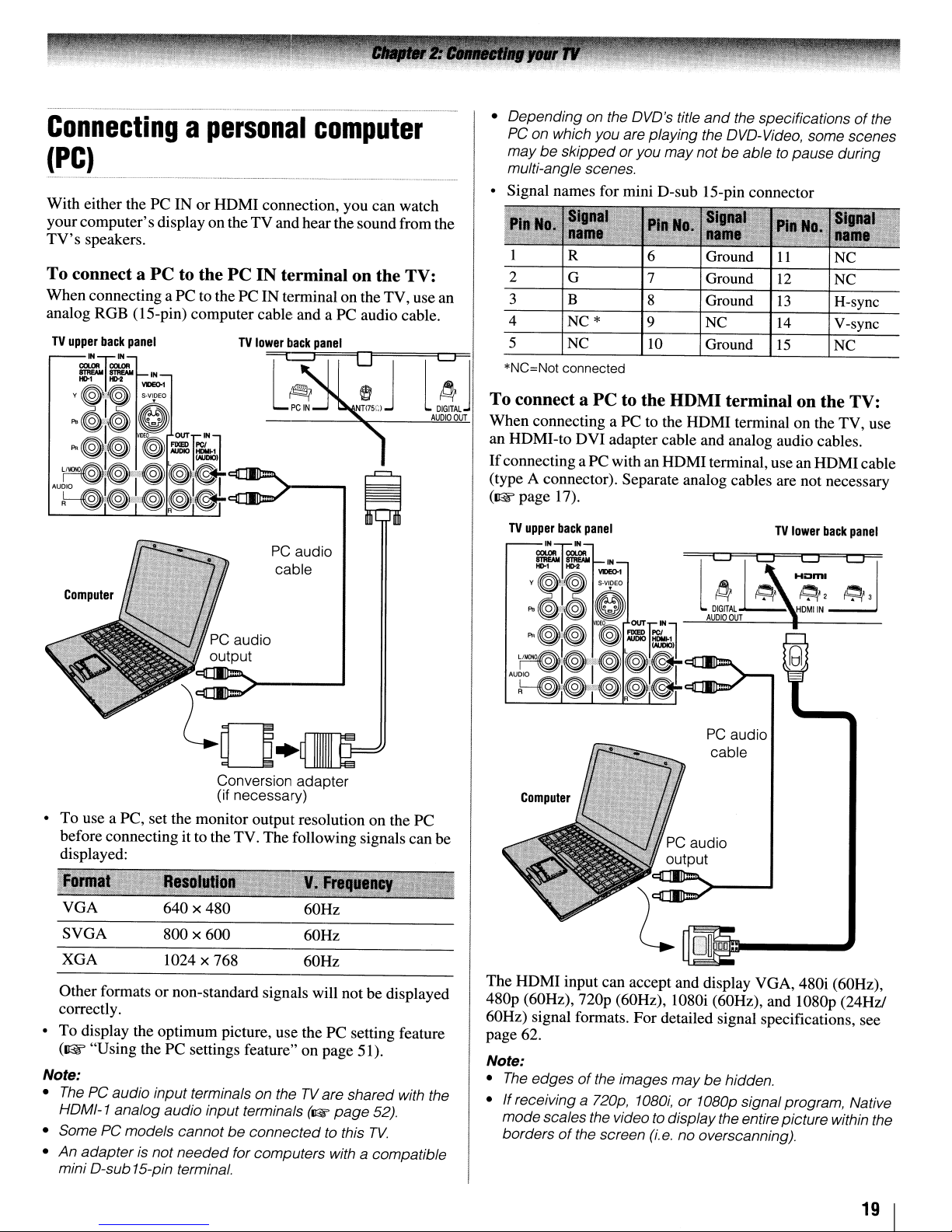
Connectingapersonal
computer
(PC)
With either the
your
computer's
TV's
speakers.
To connect a
When connecting aPCto the PCINterminalonthe TV, use an
analog RGB (IS-pin) computer cable and a
PCINor
display ontheTVand hear the soundfrom the
PC
to the
HDMI
connection, you can watch
PC
IN terminal on the TV:
PC
audio cable.
• Depending on the DVD's title
PC
on which you are playing the DVD-Video, some scenes
may be skipped
multi-angle scenes.
• Signal names for mini D-sub IS-pin connector
1 6 Ground
2 7 Ground
3 8 Ground
4 NC*
5
*NC=Not
NC
connected
or
you maynot be abletopause during
9
10
and
the specificationsofthe
'Inal
name
11
12
13
NC
Ground
14
15
NC
NC
H-sync
V-sync
NC
PC
audio
cable
Conversion adapter
(if necessary)
• To use a PC, set the monitor output resolution on the PC
before connecting it to the TV. The following signalscan
displayed:
be
To connect a
When
connecting a PC to the
an HDMI-to
If
connecting a PC with an
(type A connector). Separate analog cables are not necessary
(1l'F
page 17).
Computer
PC
to the HDMI terminal on the TV:
HDMI
DVI
adapter cable and analog audio cables.
HDMI
terminal on the TV, use
terminal, usean
TV
LJ
~CJ
~
DIGITAl
OUT
audio
cable
~
l
AUDIO
PC
HDMI
cable
lower
back
panel
H~I~~
~2
HDMIIN
~3
U
VGA
SVGA
XGA
Other formatsornon-standard signals will notbedisplayed
correctly.
To
display the optimum picture, use thePCsetting feature
•
(Il@r
"Using thePCsettings feature" on page 51).
Note:
•
ThePCaudio input terminals on theTVare shared with the
HDMI-1 analog audio input terminals
• Some
•
PC
An
adapterisnot needed for computers with a compatible
mini D-sub 15-pin terminal.
640 x 480
800
x 600
1024 x 768
models cannotbeconnected to this
60Hz
60Hz
60Hz
(II:W
page
52).
TV.
The
HDMI
480p (60Hz),
60Hz) signal formats. For detailed signal specifications, see
page 62.
Note:
•
The
•
If
receiving a 720p,
modescales the video to display the entire picture within the
borders
input can accept and display VGA, 480i (60Hz),
nop
(60Hz), 1080i (60Hz), and 1080p (24Hz!
edgesofthe images may behidden.
1080i,or1080p signalprogram, Native
of
the screen
(i.e.
no overscanning).
19 I
Preparing
for
use
YourTVremote control can operate your TV and many other
devices such as cable converterboxes, satellite receivers,
VCRs, DVDplayers, and HTIBs (hometheater in a box), even
if
they are different brands.
If
you have a Toshiba device:
Your TV remote control is preprogrammed to operate most
Toshiba devices
If
you
have a non-Toshiba device or a Toshiba device
that the remote control is not
the
(~
remote
page 24).
control
pre
programmed
to
operate:
You can program theTVremote control so it will operate the
other device
(~
pages 22-26).
• Always remove batteries from the remote control ifthey are
or
if
dead
extendedperiod
leaking into the battery compartment.
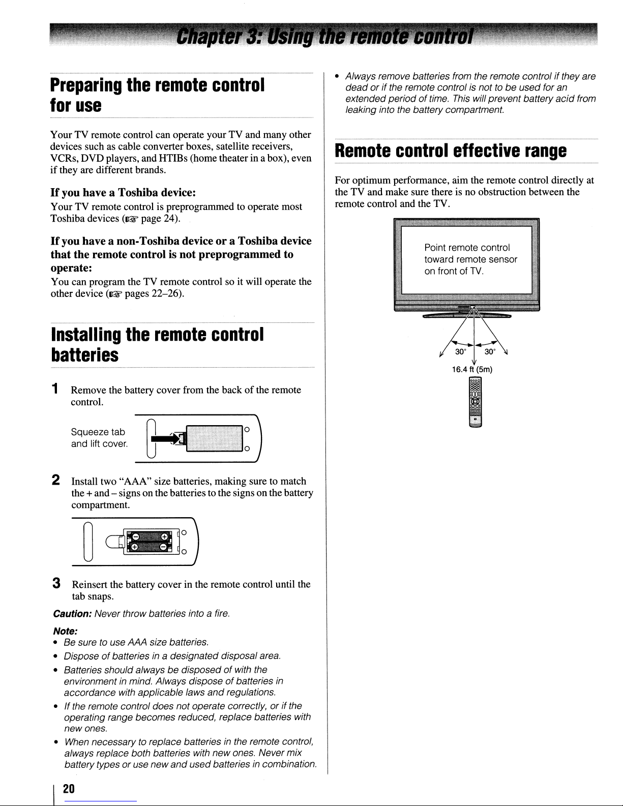
Remote
For optimum performance, aim the remote control directly at
the TV and make sure there is no obstruction between the
remote control and the TV.
the remote controlisnottobe
of
time.
This
will prevent battery
control
effective
Point remote control
toward remote sensor
on
front of
TV.
used foran
acid
range
from
Installing
the
remote
control
batteries
Remove the battery cover from the backofthe remote
1
control.
Squeeze tab
and lift cover.
2 Install two "AAA" size batteries, making sure to match
the +and - signs onthe batteries to the signs on the battery
compartment.
3 Reinsert the battery cover in the remote control until the
tab snaps.
Caution: Never throw batteries into a
Note:
• Be sure to use AAA size batteries.
of
• Dispose
• Batteries should always
environment in mind. Always dispose
accordance with applicable laws
• Ifthe remote control does notoperate correctly,
operating range becomes reduced, replace batteries with
newones.
• When necessary to replace batteries
always replace both batteries with new ones. Never mix
batterytypesoruse new
batteries
in
a designated disposal area.
be
disposedofwith the
and
and
used batteriesincombination.
o
o
fire.
of
batteries
regulations.
in
the remote control,
or
in
if
the
16.4 ft (5m)
~.~.:
..•.•.,.•
~
20
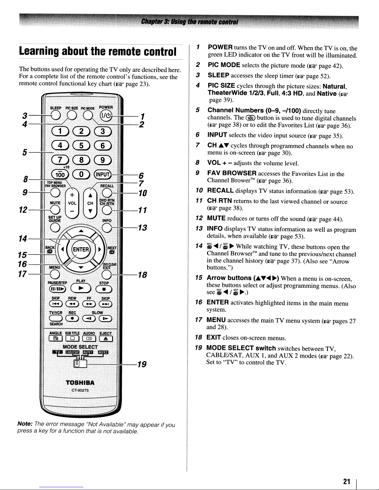
Learning
about
the
remote
control
1 POWER turns theTVon and off.
LED
green
indicator on theTVfront will be illuminated.
When
theTVis on, the
PIC MODE selects the picture
The
buttons used for operating theTVonly are described here.
For
a complete listofthe remote
remote control functional key chart
f,~
ml~2
control's
(Il@f'
page
-..1
functions, see the
23).
~-n:~:~~J
5,·
CD
(100)(])
8---!!-!-111
TOP-':::"IIEH"""""'U
FAY
BROWSER.
1:~®
~.1I.8:
IIIq
;;
16
17
11I08«.(
unU
I
MENU
-*-0
PAUSElSTEP'.PLAY
QIIII~)0~
SKIP
8.8,0:8
TVrvCR
00GDCB
S£AFlCIl
ANGLE
(]DIQI[~]I~1
.~..!fD.
.
...'.'.
+10
CD
CD
QNPU~~-6
• 7
RECAll
.11.
·~~III-::
..
INFO~.
III
13
• 0
e~~
··
REW
FF
REC,
SUB
TITlE
AUDIO
MODE SELECT
ldiJ:--------,----'-~-19
"3'
DVDCWR
EXIT
.
0:---+::---18
STOP
SKIP
SL~
~ECT
2
3 SLEEP accesses the sleep timer (1&
4
PIC SIZE cycles through the picture sizes: Natural,
TheaterWide
page 39).
Channel
5
channels.
(1&
page
6
INPUT selects the video input source (1& page
7
CH
.A....,
menu is on-screen
VOL + - adjusts the volume level.
8
FAV BROWSER accesses the Favorites List in the
9
Channel Brower™
10
RECALL displays
11
CH RTN returns to the last viewed channel
(Il@f'
page 38).
12
MUTE reduces
13
INFO displays
details, when available
14;;....
15
16
17
18
19
/;~While watching TV, these buttons open the
Channel
in the channel history
buttons.")
Arrow
these buttons select
see;;
ENTER activates highlighted items in the main menu
system.
MENU accesses the main
and 28).
EXIT closes on-screen menus.
MODE SELECT
CABLE/SAT,
Set to
buttons
....
"TV"
1/213, Full,
Numbers
The
GQQ)
38)orto edit the Favorites List (1& page 36).
cycles through programmed channels when no
Browser™
/;
~.)
AUX
to control the TV.
(0-9,
button is used to tune digital channels
(1& page 30).
(Il@f'
page 36).
TV
status information
or
turns
off
TV
status information as well as program
(Il@f'
and tune to the previous/next channel
(Il@f'
(.A....,
....
or
adjust programming menus. (Also
switch
I, and
mode
(Il@f'
page
4:3
HD, and Native (1&
-/1
00) directly tune
the sound
page
53).
page 37). (Also see
~)
When
a menu is on-screen,
TV
menu system (1& pages
switches between TV,
AUX
2 modes (1& page 22).
(Il@f'
page
42).
52).
35).
(Il@f'
page
or
source
page 44).
"Arrow
53).
27
TOSHIBA
CT·90275
Note:
The
errormessage "Not Available"
a key for a function that is not available.
press
may
appearifyou
21
I
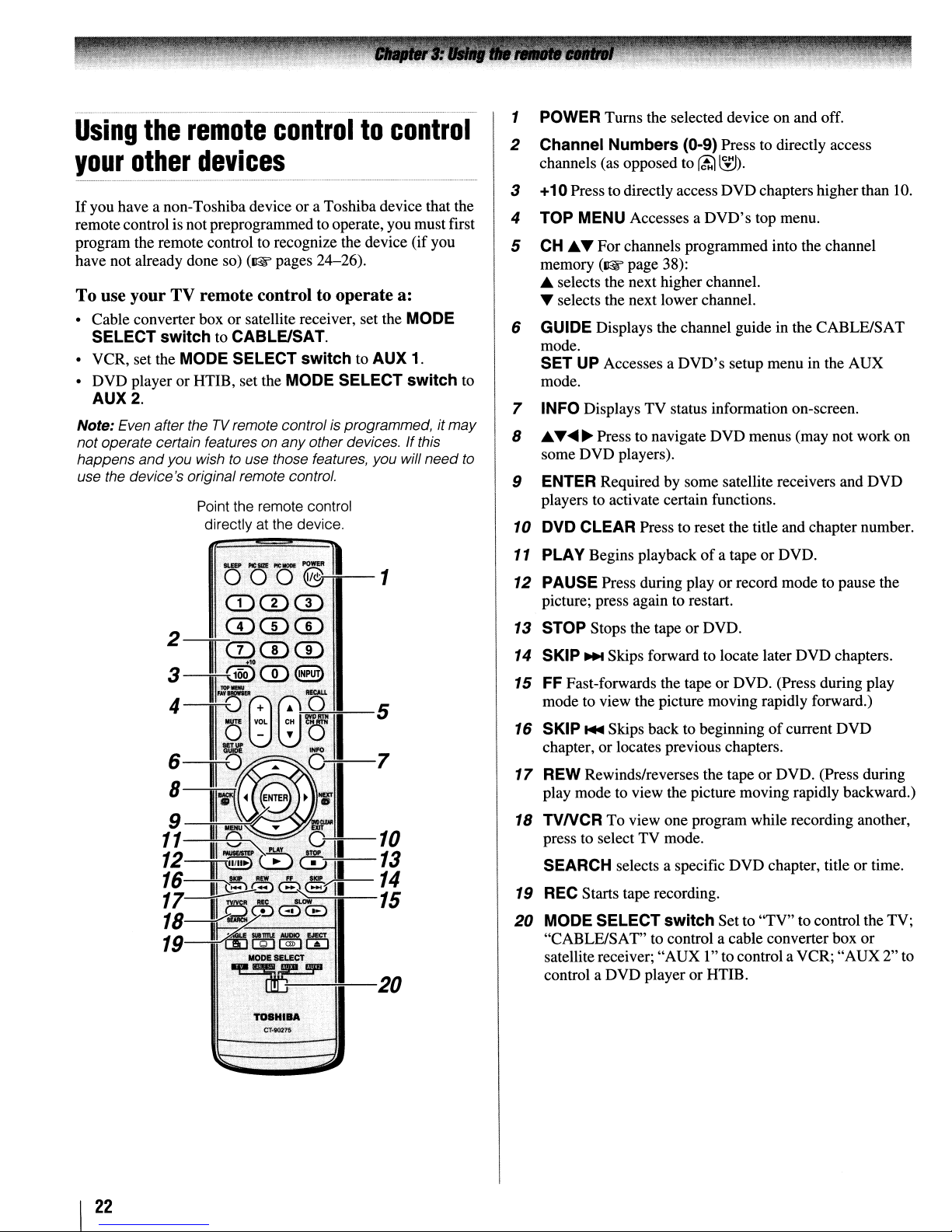
Using
your
If
you have a non-Toshiba device or a Toshiba device that the
remotecontrol is not preprogrammed to operate, you must first
program the remote control to recognize the device (if you
have not already done so)
the
other
remote
devices
(~pages
controltocontrol
24-26).
To use your TV remote control to operate a:
• Cable converter box or satellite receiver, set the MODE
SELECT
• VCR, set the MODE SELECT
• DVD player or HTIE, set the MODE SELECT switch to
AUX2.
Note: Even aftertheTVremote controlisprogrammed, it
not operate certain features on any otherdevices. Ifthis
happens
use the device's original remote control.
switch
and
you wishtouse those features, you will
to CABLE/SAT.
switch
Point the remote control
directly at the device.
to AUX 1.
may
need
1 POWER Turns the selected device on and off.
2 Channel Numbers (0-9) Press to directly access
channels (as opposed to
3 +10Press to directly accessDVD chapters higherthan 10.
4 TOP MENU Accesses a
5
CH
...~ For channels programmed into the channel
memory
...
~
(~
page 38):
selects the next higher channel.
selects the next lower channel.
(ti;1
~).
DVD's
top menu.
6 GUIDE Displays the channel guide in the CABLE/SAT
mode.
SET UP Accesses a
mode.
7 INFO Displays TV status information on-screen.
8
...~....~Press to navigate DVD menus (may not work on
to
some DVD players).
9 ENTER Required by some satellite receivers and DVD
players to activate certain functions.
10 DVD CLEAR Press to reset the title and chapter number.
11 PLAY Begins playbackofa tapeorDVD.
DVD's
setup menu in the AUX
~~-5
12
PAUSE Press during play
picture; press again to restart.
13
STOP Stops the tape or DVD.
14
SKIP
...
Skips forward to locate later DVD chapters.
15
FF Fast-forwards the tape
mode to view the picture moving rapidly forward.)
16
SKIP
...
Skips back to beginningofcurrent DVD
chapter,orlocates previous chapters.
17
REW Rewinds/reverses the tape
play mode to view the picture moving rapidly backward.)
18
TVNCR To view one program while recording another,
press to select TV mode.
SEARCH selects a specific DVD chapter, title or time.
19
REC
Starts tape recording.
20
MODE SELECT switchSet to "TV" to control the TV;
"CABLE/SAT" to control a cable converterbox
satellite receiver; "AUX 1"to controla VCR;
control a DVD playeror HTIB.
or
record mode to pause the
or
DVD. (Press during play
or
DVD. (Press during
"AUX
or
2" to
I
22
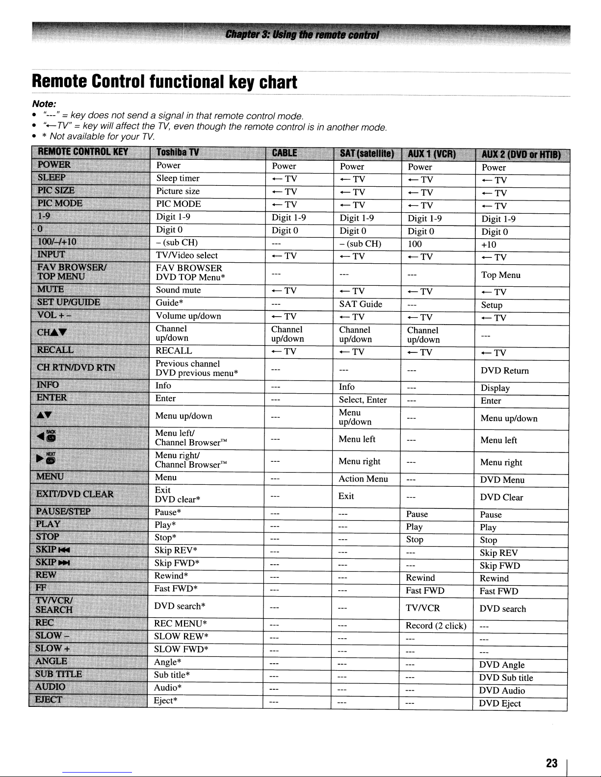
Remote
Note:
• "---" = key does not send
•
"-
TV"
Control
= key will affect the
• * Not available for your
functional
a signal
TV.
in
that remote control mode.
TV,
even though the remote control isinanother mode.
PIC
MODE
Digit 1-9
Digit
0
- (sub CH)
TVNideo
FAVBROWSER
DVD
Sound mute
Guide*
Volume up/down
Channel
up/down
RECALL
Previous channel
DVD previous menu*
Info
TOP
select
Menu*
key
chart
-TV
-TV
Digit 1-9
Digit
-TV
-TV
-TV
Channel
up/down
-TV
Power
-TV
-TV -TV
-TV
Digit 1-9 Digit 1-9 Digit 1-9
0
Digit 0 Digit 0 Digit 0
- (sub CH)
-TV -TV
-TV -TV
SAT Guide Setup
-TV -TV
Channel Channel
up/down up/down
-TV
Info
Select, Enter
Menu
up/down
-TV -TV
100 +10
-TV
-TV
-TV
Top Menu
-TV
-TV
-TV
DVDRetum
Display
Enter
Menu up/down
Play*
Stop*
Skip REV*
Skip FWD*
Rewind*
RECMENU*
SLOWREW*
SLOW FWD*
Angle*
Sub title*
Audio*
Eject*
Menu left Menu left
Menu right
Action Menu
Exit
Pause Pause
Play Play
Stop Stop
Rewind Rewind
Fast FWD Fast FWD
TVNCR
Record (2 click)
Menu right
DVDMenu
DVD Clear
Skip REV
Skip FWD
DVD search
DVDAngle
DVD Sub title
DVDAudio
DVD Eject
23
I

Programming
to
control
Your Toshiba TV remote control is preprogrammedto operate
most Toshiba devices. To program yourTV remote control to
operate a non-Toshiba device (or a Toshibadevice that it is not
preprogrammed to operate),follow the steps below. For details
on using the remote control to operate the device, see page 22.
the
your
remote
other
control
devices
1 In the remote control code table
code for your device.Ifmore than one code is listed, try
each one separately until you find one that works.
2 Set the MODE SELECT switch to the type
you are programming the remote control to operate CABLE/SAT (for a cable converter boxorsatellite
receiver), AUX 1 (for a VCR or
AUX 2 (for a DVD player or HTIB [home theater in a
box]).
3 While holding down
buttons to enter the 3-digit code for your device.
RE~L\
(w
page 25), find the
of
device
TVNCR
press the Channel Number
combo),
or
4 To test the code, turn on the device, point the remote
control at it, and press
•Ifthe correct code was entered, the device will turn off.
•
If
the device does not respond, repeat steps
another code.
•
If
the device does not respond to anothercode, you will
need to use the remote control that came with the
device.
P~ER.
See notes below.
1-4
using
S Remember to set the MODE SELECT switch back to
"TV" to control the TV.
6 For future reference, write down the code(s) you used:
Note:
• In additiontoPOWER,
TV
remote controloperate your device. Ifsome keys are not
operational, repeat the device code setup using another
code(ifothercodes are listed for yourdevice).
aI/listed codes, the necessary keys do not operate your
device, use the device's original remote control.
• Every time you change the batteries, you will need
reprogram the remote control.
• Some newer
VCRs
this kind
VCR
your
or
"VCR2")
I
24
VCRs
have a switch labeled "VCR1NCR2." Ifyour
of
switch
brand, set the switchtothe otherposition ("VCR1"
and
confirm thataI/ necessarykeys on the
respondtoeitheroftwo codes. These
and
does not respond to the codes for
reprogram the remote control.
If,
aftertrying
to
VCR
has

.
__
._._
..
__
._-_._
...
_
....
-
..
__
.
__
..
_._
.._.....
_._._-_.-_._
...
_._--_
...
Remote
_._-_._--_._---_._
control
codes
..
__
In some cases you may not be able to
operate your device with the TV
remote control. Yourother devicemay
use a code that is not recognized by the
TV remotecontrol.Ifthis happens,use
the device's remote control.
Cable
ABC
Archer
Cableview
Century
Citizen
Contec
Diamond
GE
Gemini
Hamlin
Hitachi
lasco
Motorola/GUJerrold
Magnavox
Memorex
Multi Canal
Novavision
Panasonic
Philco
Philips
Pioneer
Proscan
Radio Shack
RCA
Realistic
Recoton 102
Samsung
Scientific Atlanta
Sears
Signature
Signature 2000
Sprucer
Starcom
Stargate
Sylvania
TeleView
Texscan
Tocom
U.S.Electronics
United Cable
Universal
Wards
Satellite
Alphastar
Chaparral
DISH Network
converter
receiver
box
061,062,063,082,
084,087,092,
096,098
065,092,097,099
064,094
092
090,092,097
083,085,086,088,
093,098
093
061,062
069,070,094
093
062,095,096
097
062,069,071,082,
086,089,096,107
072,096
092, 104
090
101
081,083,085
087
066, 067, 068, 070,
072,073,074,075,
092
076,077
061,062
092,097,099
064,081
065
077,090
063,078,079,080,
088,098, 101,
095
062
096
081,085
069,082,087,096,
103, 104 VCR=081
069,090
095, 100 VCR=082
090
100
071,084,085
087,096,098
082
065,092,097,099,
102,103
096 VCR=086 Broksonic
038,059
034
057
105
..
_.-
Drake
Echostar 018,041,051
Express Vu
Fujitsu
GE
General Instruments
Hitachi
Hughes
Hughes Network
Systems
Intersat
laneil
lVC
Kenwood
Magnavox
Optimus
Pansat
Primestar
Proscan
Radio Shack
RCA
Realistic
Samsung
Sony
Star Choice
Star Trak
STS
Toshiba
Uniden
Zenith
TVNCR
Action
GE
Goldstar
Panasonic
Precision
Quasar
Realistic
Sony
Toshiba
Zenith
Totevision
DVDNCR
Go Video
lVC
RCA
Samsung
Sanyo
Zenith
DVD
Aiwa
Apex
BOSE
Broksonic
Combo
Combo
player
020, 040, 044, 046,
050,053
057
027
008,009,013
010,011,012,022,
023,031,049
033 Go Video
033 GPX
019
048
027
017,057
029
060
058
036,052
015,042
008,009,013
022,023,030
008,009,013,016
030 Oritron
059 Panasonic
014,055
057, 106
025,026,037,054
024
000,001,002,003,
004,005,006,007,
020,031,056
021,028,030,032,
035,039,043,045,
047,058
027
078
059,062
065
065
078
065
079
074
057
065
009,010,065
DVD=087,
DVD=088,
DVD=089,
VCR=083
DVD=090,
VCR=084
DVD=091,
VCR=085
DVD=092,
006,015
016,017
097
018
Clarion
Classic
Daewoo
Denon
Emerson
Fisher
Funai
GE
Hitachi
lVC
Kenwood
Konka
Magnavox
Memorex
Mintek
NAD
Nakamichi
Norcent
Onkyo
Philips
Pioneer
Proscan
Qwestar
RCA
Sampo
Samsung
Sansui
Sanyo
Sharp
Sherwood
Sony
Sylvania
Teac
Technics
Techwood
Toshiba
Yamaha
Zenith
Portable
Aiwa
Audiovox
Panasonic
RCA
VCR
Admiral
Aiko
Aiwa
Akai
Audiovox
& Howell
Bell
Calix
Carver
CCE
Citizen
Colortyme
DVD
019
020
021
022,023,024,025
026,027
028
027
001,029,030
087
031
005,032,033,034,
035
003,007,036,042,
088
037
008,009
004,038
039
040
026
041
043
044
058
010,045,046,047,
048,049,050
004,051
052,053,054,055
001,056
057,058
001,002,059,089
060
061,062,086,090
073
063,091
064,067
074
011,012,065,066,
068,069,070
027
071
072
075
000,013,076,077,
078
079,080,081
014,082,092
player
093
094,095
024,096,099
098
049
019
018
003,004,037,038,
039,058,069
010
007,068
008,017
010
026
019
009,010,011,012,
013,014,015,019,
057,073
005
(continued)
25
I

Craig
Curtis Mathes
Daewoo
Daytron
Denon
Dimensia
Electrohome
Emerson
Fisher
Fuji
Funai
Garrard
GE
Go
Video
Goldstar
Gradiente 018,065
Harman Kardon
Hitachi
JBL
JC Penney
Jensen
JVC
Kenwood 005,006,007,012,
Kodak
LG
Lloyds 053,073,079
Logik
LXI
Magnasonic
Magnavox
Marantz 005,006,007,012,
Memorex 007,009,010,016,
MGA
MGN
Minolta 024,025,035,063
Mitsubishi
Montgomery Ward
Motorola
MTC 009,046,061
Multitech 009,012,018
NEC
Nikko
Noblex
Optimus 010,049,065
Optonica
009,010,016,061,
065,079
001,005,009,012,
014,040,048,053,
056,057
011,013,015,017,
018,019,057,078
078
063
001,048
010,020,065
003,008,010, OIl,
017,018,020,028,
039,054,057,062,
065,068,072
007,016,021,022,
023,057,064,068,
070,071,079
004,041
018,073
018
001,002,009,040,
042,048,056
056,059,061,081
005,010,014,054,
056,065,067
005
024,025,035,037,
042,063,070,080
076
005,006,007,008,
009,010,023,024,
025, 026, 035, 056,
061,063,065
024,025,037,050
005,006,007,014,
037,043,055,062,
063,068,082
014,037,043,050,
053,068,071
010
010
061
010
061,065,078
026,027,034,044,
057,061,072
014,026,053,067
018,034,049,063,
065,066,068,075,
079
020,028,039
056
020,024,025,028,
039,043,065
049 Teac
049 Technics
005,006,007,012,
014,037,043,053,
054,067,070 Totevision
010
009
031
Orion
Panasonic
Pentax
Pentex Research
Philco
Philips
Pioneer
Portland
Proscan
Proton
Quasar
Radio Shack
Radio Shack/Realistic
Radix
RCA
Realistic
Ricoh
Runco
Samsung 009,
Sansui
Sanyo 007,009,016,054,
Scott 008,011,017,028,
Sears
Sharp
Shintom
Signature
Signature 2000
Singer
Sony
STS
Sylvania 018,026,027,028,
Symphonic 018,050,051,053,
Tandy
Tashiko
Tatung
Teknika 010,018,065
Toshiba
Unitec
Unitech
Vector Research 005,006,
054,057,062,065,
068,072
036,045,046,057,
061,072,079
012,024,025,035,
042,053,063
014
026,027,063
026,031,044,057
006,024,043,055
012,013,015
001,002,048
061
045
010,031,065
007,009,010,016,
018,020,021,022,
031,049
010
001,002,003,009,
024,025,029,035,
040, 042, 045, 048,
055,056,063,071,
083
007,009,010, OIl,
016,018,020,021,
022,031,049,051,
056,060,065,075,
079
047
034
Oil,
073,084
006,037,043,061
064,068,071,075,
079,085
030,057,065,072
007,010,016,021,
022, 023, 024, 025,
035,053,057,063,
064,065,068,071,
075,079
013,020,031,049,
051,060,066
004,025,032,061
049
075
047,061
004,032,033,041,
052,058,070,074,
076,077,080
035
044,072
073,079
007
010
037
018,029,037
036
000,011,021,023,
024,028,030,039,
057,074,078,079
009,010,065
073
009
053
038, 056,
OIl,
012,
Video Concepts
Wards
White Westinghouse
XR-l000
Yamaha
Zenith
HTIB
Lasonic
Panasonic
Venturer
Oil,
Oil,
012,
016,
005,006,
039,053
009,010,
018,020,024,025,
031,035,049,051,
056,057,060,065,
066,079
073
018
005,006,007,014,
037,053
004,032,034,041,
047,069,086
083
084
085
26
I

Main
menu
layout
The tables below and on the next page provide a quick overviewofyour
To open the main menus (illustrated below), press
Video
Mode
Picture Settings
Noise Reduction
Game Mode
Theater Settings
Audio
Digital Audio Selector
Audio Settings
Advanced Audio Settings
Audio Setup
Preferences
CC Selector
Base CC Mode
Digital CC Settings
Input Labeling
Channel Labeling
Menu Language
Channel Browser Setup
Locks
Enable Rating Blocking
Edit Rating Limits
Channels Block
Input Lock
Front Panel Lock
New PIN Code
Setup
Installation
Sleep Timer
HDMI Settings*
PC Settings
Power-On Mode
M~U
on the remote control or TV control panel.
-+
Sports/StandardIMovie/Preference
-+
[Opens the Picture Settings menu]
-+
[Opens the Noise Reduction menu]
-+
On/Off
-+
[Opens the Theater Settings menu]
-+
[Launches the temporary Audio Selector]
-+
[Opens the Audio Settings menu]
-+
[Opens the Advanced Audio Settings menu]
-+
[Opens the Audio Setup menu]
-+
[Launches the temporary CC Selector]
-+
OffiCC
-+
[Opens the Digital CC Setup menu]
-+
[Opens the Input Labeling menu]
-+
[Opens the Channel Labeling menu]
-+
English/French/Spanish
-+
[Opens the Channel Browser Setup menu]
-+
Off/On
-+
[Opens the Edit Rating Limits menu]
-+
[Opens the Channels block menu]
-+
OffNideoNideo+
-+
Off/On
-+
[Opens the New PIN Code entry screen]
-+
[Opens the Installation menu (I&' page 28)]
-+
[Opens the Sleep Timer menu]
-+
[Opens the HDMI Settings menu]
-+
[Opens the PC Settings menu]
-+
Power-SavingiFast
I/CC2/CC3/CC4/T1/T2/T3/T4
TV's
menu system.
* HDMI settings menu is only for models 26HL47, 32HL67US, 37HL67S, and 42HL67US.
27
I

Setup/Installation
The Installation menu contains the Terrestrial and System Status menus.
To
open the Installation menu (illustrated below), press
select Installation, and press @.
menu
layout
M~U
on the remote controlorTV control panel, open the Setup menu,
t
Press
M~U,
open the
Setup menu,
and then
open the
Installation
sub-menu.
Terrestrial
System Status
System Information
-+
[Opens the Input Configuration menu]
-+
[Start]-+[Scans for new channels on ANT]
-+
[Opens the Channel AddlDelete menu]
-+
[Opens the Signal Meter menu]
-+
[Opens the System Information screen]
Navigating
You can use the buttons on the remote control orTVcontrol
panel to access and navigate your
system.
• Press
• When a menu is open, use the up/down/leftJright arrow
• Press @ to save your menu settingsorselect a highlighted
• All menus close automaticallyifyou do not make aselection
•
M~U
buttons (• .......~)on the remote controlorTV controlpanel
to move in the corresponding direction in the menu.
item. (A highlighted menu item appears in a different color
in the menu.)
within 60 seconds, except the signal meter menu, which
closes automatically after about 5 minutes.
To
close a menu instantly,
the
menu
TV's
to open the menu system.
press~.
system
on-screen menu
Note:
•
The
menu backgroundmay sometimes appear black,
depending on the signal the
signofmalfunction.
•
The
Video sub-menu appears with a black background,
which looks different from other menus.
TVisreceiving.
Thisisnot a
I
28

Selecting
the
menu
language
Configuring
the
antenna
input
You can choose from three different languages (English,
French and Spanish) for the on-screen display
messages.
To selectthe menu language:
1 Press
2 Highlight Menu Language and
3 Press ... or
4 Press
M~U
press@.
E'g
and open the Preferences menu.
press~.
'Y
to select your preferred menu language and
to close the Preferences menu.
of
menus and
source
To configure the ANT input source:
1 Press
2 Highlight Installation and press
3 (A new set
shown below.) Open the
Input Configuration, and press
for
the
ANT
M~U
and open the Setup menu.
of
Installation menu icons will appear, as
Terrestrial menu, highlight
terminal
@.
@.
4 Press
....
or~to select the input source (Cable or
Antenna) for the ANT input on the TV.
5 To save your new settings, highlight Done and press
To revert to your original settings, highlight Cancel and
press@.
@.
29
I

Programming
TV's
channel
channels
memory
into
the
4 (A new set
shown below.) Open the Terrestrial menu, highlight
Channel Program to bring up the Start, and press @
again to begin channel programming.
of
Installation menu icons will appear, as
When you press
panel, yourTVwill stoponly onthe channelsyou programmed
into the
Follow the steps below to program channels into the
channel memory.
TV's
Programming
Your TV can automatically detect all active channels in your
area and store them in its memory. After the channels are
programmed automatically, you can manually addorerase
individual channels in the channel memory.
Note:
•
You
must configure the antenna input source before
programming channels
• If the Antennainputsignaltype
channel programming process erases channels that were
previouslyprogrammed into the
• If the Antenna inputsignal type is set
automatic channel programming processadds newly found
channels to the existing setofprogrammed channels (and
does NOTerase channels that were previously
programmedinto the
source channelfrom the memory, youmustmanually delete
it.
•
To
tune theTVto a channelnotprogrammedinthe channel
memory, you mustuse the Channel Number buttons on the
remote control.
• Programming channels when the antenna input
configuredfor Cable willtake substantiallylongerthan when
the antenna input is configuredfor
however, once channelprogramming
not
havetorepeat the programming process again unless
your Cable
To program channels automatically:
1 Configure the antenna input source,
already done so (1& page 29).
2 Press
ft.;)
or~on the remote control orTVcontrol
channel memory.
channels
TV's
TV
service lineup changes significantly
M~U
and open the Setup menu.
automatically
(1&
page
29).
is
setto Cable, the automatic
TV's
memory)Toremove anAntenna
Antenna.
TV's
memory
to
Antenna, the
is
This
is normal;
is
finished, youshould
if
you have not
The TV will automatically cycle through all the antenna
channels, and store all active channels in the channel
memory. While the TV is cycling through the channels,
the message "Scanning channels,please wait" appears (as
shown above).
5 To cancel channel programming, press
control (or highlight Abort in the on-screen display and
press@).
When channel programming is finished, press
view the programmed channels.
Manually
in
the
After automatically programming channels into the channel
memory, you can manually addordelete individual channels.
To addordelete channels in the channel memory:
1 Press
adding
channel
M~U
and open the Setup menu.
and
memory
deleting
2 Highlight Installation and press
3 (A new set
shown below.) Open the Terrestrial menu, highlight
Channel Add/Delete, and then press
of
Installation menu icons will appear, as
E~T
channels
@.
@.
on the remote
ft.;)
or~to
3 Highlight Installation and press
I
30
@.

To
add
a channel to the channel memory:
Highlight the unchecked box next to the channel number you
want to add, and then press @ to check the box.
To manually
add
digital subchannels on a physical
channel:
Use the Channel Numbers and the Dash
control to enter the channel number (for example, 56-1).
If
the channelisfound, the number will be added to the listand
the box will be checked.
If
the channel is not found, a message will appear.
(GQ2)
on the remote
To remove a channel from the channel memory:
Highlight the checked box next to the channel number you
want to remove, and then press @
to
uncheck the box.
To save your new settings:
Highlight Done and press
To
reverttoyour
Highlight Cancel and press @ before saving.
@.
original settings:
To remove all channels from the channel memory:
Highlight Reset and press
press@.
@,
and then highlight Done and
Labeling
A listofcommon channel labels (logos) for various channels
(ABC, CBS, etc.) will be programmed into the TV. You will
be able to view and assign these logos from the
Labeling
in the list, you will be able to manually enter/edit labels using
the software keyboard.
channels
Channel
window.Ifthe desiredchannel label is not provided
To assign channel labels:
1 Press
2 Highlight Channel Labeling and press
M~U
and open the Preferences menu.
The Channel Labeling window opens.
@.
Channel Add/Delete
To remove encrypted channels from the channel
memory:
If
an encryptedchannel is accidentallyadded to thechannel list
by programming channels, you can remove the unwanted
encrypted (non-viewable) channel while you are channel
surfing. When you tunes to an encrypted channel, the
following message will appear.
Press
"Q)"
button while the message is on the screen to
remove the unnecessary channel from the channel list.
3 Press
4 Press A
r£1
press@.
or~to select the channel you want to label.
T~
~
to highlight the desired channel label and
5 Repeat steps 3 and 4 for other channels.
6 To save your settings, highlight Done and press @.
The maximum numberoflabels that can be stored is 128.
To remove channel labels:
1 Open the Channel Labeling window.
2 Press
r£1
or~to select the channelfor which you want to
remove the label.
(continued)
31
I

3 Press
~T~
~
to highlight No Label and press
4 Repeat steps 2 and 3 for other channels.
S To save your settings, highlight Done and press
If
the desired channel label is not available from the list
presets, you can create a custom label.
To create
and
assign a custom label:
@.
@.
of
3 Highlight Yes from the deletion confirmation window
and
press@.
Channel
labeling
4 Highlight Done and press @ to save changes, and go
back to the Channel Labeling window.
Setting
.....................
-.
the
_ .
HDMI™
audio
mode
1 Open the Channel Labeling window.
2 Press
3 Press
4 Repeatedly press the corresponding key on the remote
S The highlighted character
6 Repeat steps 4 and 5 until you have entered all desired
7 When finished, press @.
(£)
or~to select a channel you want to label.
~T~
to highlight Custom and press
The software keyboard will appear.
Channel
Labelmg
control to highlightthe desired character on the on-screen
software keyboard.
is
entered after you either press
a different key, press~key,orafter a two-second pause.
text.
@.
8 (New labels will be added to the list in alphabetical order
and marked with an icon I to indicate that they are
custom.) Highlight the new custom label and press @ to
assign. Assigned channel labels will be displayed in the
banner, Channel Add/Delete window, and Channels
Block
window.
To set the HDMI audio mode:
1 Press
2 Highlight
3 Press
Note:
of
analog audio inputs, the PC
the
HDM/1
"Yes, " the HDM/1
grayed outinthe menu. (Also see item 4 on
"Setting thePCAudio"on
M~U
and open the
Audio
~
or T to select HDMI1
~or~
to select the HDMI 1audio mode (Auto, Digital,
or
Analog). (Auto is the recommended mode.) See
"Connectingan HDMI or DVI deviceto the HDMIinput"
(~page
Because thePCand
HDM/1
17).
Audio
Audio
setting changes
menu setting. IfPC
Audio
Audio
Setup and press
HOMI-1 inputs share the same set
setting is set
page
menu.
@.
Audio
Audio
to
"Auto. "IfPC
52.)
and then press
menu setting influences
Audio
is set
to
"Digital"
page11and
Audio
to
and
"No,
is set
"the
to
is
To delete the custom label:
1 Open the Channel Labeling window.
2 Highlight the label to be deleted and press
I
32
CWo

Viewing
the
digital
signal
meter
Viewing
the
system
status
---
You can view the digital signal meter in the ANT digital TV
input source only.
To view the digital signal meter:
1 Press
M~U
and open the Setup menu.
2 Highlight Installationand press @.
3 A new setoflnstallation menu icons will appear, as shown
below. Open the
Meter,
and
4 Press'".......
channel whose signal you want to check.
Note:
The
Signal Meter screen may not correspond
channel number. Contact yourlocal broadcasters
obtain the RF channelnumbers for yourlocal digital
stations.
Terrestrial menu, highlight Signal
press@.
~
to select the antenna input and digital
physical digital channel number listedinthe
to
a virtual
TV
to
To view the system status:
1 Press
2 Highlight Installation and press
M~U
and open the Setup menu.
@.
3 A new set oflnstallation menu icons will appear,
below. Open the
System Information, and press
4 Press
To close the screen
menu:
Highlight Done and press
....~to scroll through the menu bar to select the
Software Version and view the related information.
System Status menu, highlight
@.
and
return
@.
to the Installation
as
shown
To close the screen
menu:
Highlight Done and press
To
returntonormal
Press
E~r
and
return
@.
viewing:
to the Terrestrial
To
return
Press
Reset
To reset all settings
default values:
1 Press
2 Highlight Installation and press
Installation menu icons will appear.
to normal viewing:
E~r
Factory
Defaults
M~U
and open the Setup menu.
and
channels to
their
@.
A new set
factory
of
3 Open the System Status menu, highlight System
Information,
4 Press
....~to scroll through the menu bar to select
Factory Defaults.
5 Enter your PINcode (or 0000
and press
@.
ifnoPIN codehas been set).
(continued)
33
I

6 Highlight Yes and press
automatically after a few seconds. After the TV turns off,
unplug the TV power cord and then plug it in again to
complete the reset process.
8.
The TV will tum
off
I
Selecting
You can select either Power-Saving
o Power-Saving modekeeps powerconsumption in standby
mode to below 3W. As a result, it takes a bit longer to tum
on.
o Fast mode increases power consumption
As a result, the TV will tum on quicker. While in Fast
mode, the yellow LED on the TV front will be lit.
the
Power-On
Mode
or
Fast mode.
in
standby mode.
To cancel the reset:
Highlight No and press
8.
To set the Power-On Mode feature:
1 Press
2 Highlight Power-On Mode and
3
Press'"
press
M~U,
and open the Setup menu.
or'"
to selecteither Power-Saving
8.
press~.
or
Fast and
I
34

Selecting
to
view
the
video
input
source
To select the video input source to view:
1 Press
~
on the remote control or TV control panel.
2 And then either:
0-8;
a) Press
b) Repeatedly press
press
c) Repeatedly press
control panel to change the input.
The current signal source displays in the top right comer
of
the Input Selection screen.
Note:
•
You
can label the video input sources accordingtothe
specific devices you have connected
(1& "Labeling the video input sources"
• Sources can be "hidden"
sources"
"No
Video Signal" will appear randomly on the screenifno
•
signal
is
or
~~
on the remote control and then
@ to change the input; or
~
on the remote control or TV
10
ANT
o Video 1
6 Video 2
6)
CoiorStream
G ColorStream
HD1
HD2
o HDMI1
(1)
HDMI2
o
HDMI3
Qpc
o .Q I
CD
to
Select"
Navigate
(1& "Labeling the video input
at
right).
receivedinvideo input mode.
to
the
TV
at
right).
Labeling
You can label each video input source according to the type
device you connected to each source,from the following preset
of
labels:
list
• - - (default label)
• Audio Receiver
• Cable
• Compact Disc
• DTV
• DVD
• Game Console
•
HDDVD
• Laser Disk
• SatellitelDSS
• VCR
• Video Recorder
• Hide (to hide an unused input in the
Note: Ifyou select
choose only
the
video
PCinthe Input Selection screen, you can
"--"or "Hide" as the label.
input
sources
Input Selectionscreen)
of
To label the video input sources:
1 Press
2 Highlight Input
3 Press
label.
M~U
and open the Preferences menu.
~or~
labeling
to highlight the video source you want to
and press
@.
(continued)
35
I

4 Press
source.
....
or~to select the desired label for that input
If
a particular input is not used, you can select
Hide as the label, which will cause that input to be
"grayed out" in the Input Selection screen and skipped
~
over when you press
5
To
save the new input labels, highlight Done and
on the remote control.
press@.
To revert to the factory default labels, highlight Reset
andpress@.
Input
labeling example:
The screen below left shows the default Input Selection
screen (with noneofthe inputs labeled as a specific device).
of
The screen below right is an example
if
the inputs
you connected a VCR to VIDEOI,Cable TV to
VIDEO 2, a video recorder to ColorStream
I,
top box toHDMI
a satellitelDSS set-top box to HDMI 2, and
how you could label
HDI,
a DTV set-
a DVD player to HDMI 3. Alsonote that the ColorStreamHD2
input is labeled "Hidden," which means that input will be
~
skipped overwhen
10
ANT
o
Video
1
f)
Video
2
e
ColorStream
•
(j)
I
CD
Selection
labeled.
HDl
H02
to Select Navigate
screen
e ColorSlream
0HDMIl
o HDMI2
G HDMI3
(j)PC
(j)
Input
no
inputs
is pressed.
with
10
ANT
o
VCR
f)
Cable
e
Video
e
ColorSlream
o
DTV
o Satellite/OSS
G
DVD
(j)PC
(j)
.
Input
all
inputs
which
Recorder
(j)
I
CD
Selection
labeled
has
been
H02
(Hidden)
to Select • N.YlgeIe
screen
with
except
input
hidden.
4,
To clear the input labels:
Tuning
Tuning
Channel
The Channel
channels
channels
Browser™
Browser™
using
provides an easy navigation interface
the
for all your channels and inputs. This feature allows you to:
of
• Navigate the contents
• Keep a list
of
your favorite channels (see "Favorites
allofyour inputs.
Browser," below).
of
• Keep a history
the last 32 channels or inputs viewed.
• Quickly surfand tune your recently viewed channels/inputs
from the Channel
Browser™
History List (illustrated on the
next page).
• Surf via Browsemode (toimmediately tune channels as you
or
highlightthem inthe Channel Browser™)
surf over channels in the Channel
Browser™
Selectmode (to
before you
select one to tune).
• Quickly change inputs from the Inputs List.
Favorites
Browser
The Favorites Browser allows you to quickly set up a favorite
channels/inputs list that is integrated into the Channel
To
add
a favorite channeVinput:
1 Tune to the channel
2 Press and hold
Note:
Additionsare
on the left side
of
or
input.
FAV
BR~5ER
for 3 seconds.
added
to the
beginningofthe Favorites list
the Channel Browser™.
Browser™.
1 Press
M~U
and open the Preferences menu.
2 Highlight Input Labeling and press
3 Highlight Reset and press
@.
@.
To delete a favorite channeVinput:
1 Press
2 Highlight the channel
FAVB~ER
;
....
Ort;~.
to open the Favorites browser list.
or
input to delete by pressing
3 Press and hold @ for 3 seconds. The channeVinput will
be removed from the Favorites list.
To setupthe Channel Browser™:
1 Press
2 Highlight Channel Browser Setup and press
3
M~U
and open the Preferences menu.
Press.
to highlight Navigation, and then press
to select either Browse Mode
or
Select Mode.
@.
....
or
~
I
36

4
Press'"
to select the setting you prefer: either Power
(On), On,
Note: When
Mode
inputs storedinthe list willbesaved every
cycle. When
the channels
with every
5
Press'"
select
6
Press'"
to select On
7
Press'"
select
to highlight
or
History
(~page
History
and
power
to highlight ANT List, and then
History
List, and then
Off.
List
is set to On
34) is in
on/offcycleofthe
Fast
mode, the channels
List
is
set to
inputs stored in the list willbecleared
On or Off.
to highlight
or
to highlight FavoritesList, then
Off.
Inputs
List, and then
On or Off.
and
Power
TV.
press'"
the Power-On
power
Off
Clear(On),
press'"
press'"
press'"
Off
or
Clear
and
on/off
or~to
or
or~to
~
~
•Ifall lists are turned
not display the Channel
turned off,
• Pressing
Favorites list regardlessofthe last selected listin the
Channel
FAYB~SER
FAY
BRO'SER
Browser™.
To tune to a channelorinput
1 While watching TV,
Channel
surfforward to the next item in the list.
In
Channel Browser™, it will be highlighted and the TV will
automatically tune to the channel or input.
2 Press
Browser™
Browse mode, when you stop on an item in the
E'8
to close the Channel Browser™.
off,
pressing:;
Browser™.
will have no effect.
will bring up the Channel
.....
,
;~,
If
Favorites
or
FAY
Browser™
in Browse mode:
press:;'"
and surf back to a previous item or
or;;~to open the
B~SER
List
is
will
8 To save your entries, highlight Done and press
To return to factory defaults, highlight Reset and
press
S.
To open
•
Press:;'"or;;~on the remote control.
Press:;'"
•
channels in theHistory list,the channelsin the
list, the inputs in the Inputs list, or the favorite channels/
inputs in Favorites list.
Press;;~to surf forward through the channel History, the
•
ANT channel list, the Inputs list, or the favorite channels/
inputs in Favorites list.
Elementsofthe
the
Channel Browser™:
to surfbackward through thepreviously tuned 32
Channel
Browser™
2
ANT
S.
channel
4
6
Current list (History, ANT, Inputs, or Favorites)
1
2
Input type
3
Channel or input currently being viewed
4
Channel or input that is currently highlighted in the
browser
Channels stored in the History List
5
6
Channel labels
To tune to a channelorinput
1 While watching TV,
Channel
forward to the next item in the list.
In
Browser™, it will be highlighted but you must press
tune the TV to the highlighted item.
Browser™
Selectmode, when you stop on an item in the Channel
press:;
and surfback to a previous item
in Select mode:
... or
;;~to open the
or
S to
2 Press S to tune the TV to the highlighted item.
3 Press E8 to close the Channel Browser™.
Adding
History
Adding channels
As a channel or input is tuned, the Channel
to the History List and displays it on the "right side"
Channel Browser™. Previously tuned channels/inputs are
"shifted" to the left, eventually moving
:;
inputs. Any channel or input that is tuned repeatedly will not
be repeatedin the History List, but insteadis moved to the end
of
The Channel
• All channels thatare tuned usingthe numeric buttons onthe
• All channels that are tuned using
Note: Whenever an item is selected that cannot
various reasons), the
previously viewed channel or input.
and
clearing
channels
and
inputsinthe
List
and
inputs to the History List:
Browser™
off
the left side. Press
... to surf backward through the previously tuned channels/
the list on the right sideofthe Channel Browser™.
Browser™
remote control.
control.
will store the following channels:
(ti;)
or~on the remote
TV
will automatically tune to the
of
be
tuned (for
adds it
the
To toggle among the available lists:
After opening the Channel Browser™,
among
Note:
•
History, ANT, Inputs, and Favorites.
The
Channel
Once another list hasbeen selectee], the Channel
will open in the last selectedlist.
Browser™
opens in
press.
History
List
or'"
by
to toggle
default.
Browser™
(continued)
37
I

Clearing channels from the History List:
• Reconfiguring the ANT input will clear the History List.
Note: See
input.
• Once 32 channelsorinputs are stored in the History List, the
oldest item will be removed from the list when a new
channel or input is tuned.
•
If
History Listin the Channel Browser Setup is set to
"PowerOff Clear(On),"turning
History List.
Tuningtothe
page29for details on configuring the antenna
off
theTVwill clearthe
next
programmed
channel
To tune to the next programmed channel:
Press
(t,;)
or~on the remote controlorTV
Note:This feature will not work unless you program channels
TV's
into the
Tuningtoa
or
unprogrammed)
channel memory
specific
(I@"
page
channel
control panel.
30).
(programmed
Tuning analog channels:
Press the Channel Number
example, to select channel
(0-9)
on the remote control. For
125, press
1,2,5,
then
@.
Switching
between
two
channels
using
SurfLock™
The
SurfLock™
to the
CH8N
from any other channel by pressing
channel to the
1 Tune the
CH~button.
2 Press and hold
"Channel Memorized" appears on-screen. The channel
has been programmed to the
feature temporarily "memorizes" one channel
button, so you can return to that channel quickly
CH~.
To
memorize a
CH8N
button:
TV
to the channel you want to program into the
CHOTN
for about2 seconds until the message
CH~
button.
3 You can then change channels repeatedly, and when you
press
CON,
the memorized channel will be tuned.
TV
The
Once you press
RTN memory will be cleared and the button will function as
Channel Return, by switching back and forth between the last
two channels that are tuned. This feature also works for
external inputs.
will return to the memorized channel one time only.
CH8N
and then change channels again, the
CH
Tuning digital channels:
Press the Channel Number
followed by the dash
number. For example, to selectdigital channel
2,5,-,1,
Note: If a digital channelis not
the automatic channel scan
delete function
channel using the Channel Number
remote control.
Switching
Channel
The Channel Return feature allows you to switch between two
channels withoutentering an actual channel number each time.
then@.
(I@"
between
Return
page
(0-9)
on the remote control,
(@)
button and then the sub-channel
programmed-either
(I@"
page
30)orthe channel
30)-you
will havetotune the RF
and
dash
two
channels
125-1, press
through
(@)
on the
using
add/
1 Select the first channel you want to view.
2 Select a second channel using the Channel Number
«(W)
buttons (and the dash
channel).
3 Press
CHOTN
on the remote control.
will display. Each time you press
back and forth between the last two channels that were
tuned.
Note: If you press
will returntothe last-viewed input.
CH~
buttonifselecting a digital
The
previous channel
CH8N,
theTVwill switch
from a non-antenna input, the
TV
1,
I 38

Selecting
You can view many program formats in a varietyofpicture
sizes-Natural,
TheaterWide 3, Full, 4:3 HD and Native.
Note:
The
formatofthe image (in anyofthe picture sizes) will vary
depending on the format
watching. Select the picture size that displays the current
program the way that looks best
You can save separate picture size preferences for each input
on your TV.
the
picture
TheaterWide 1, TheaterWide
"picture size" illustrations are examples only.
of
the signalyou are currently
to
size
2,
you.
The
Note:
If
you select oneofthe TheaterWide® picture sizes, the
top
and
bottom edgesofthe picture (including subtitles
captions) maybe hidden.Toview the hidden edges, either
scroll the picture
program in
Natural
• The image is displayed close to its originally formatted
picture
proportion. Some program formats will display with
sidebars and/or bars at the top and bottom.
000
(TheaterWide 2
FullorNatural picture size.
and
size
000
3 only)
or
try viewing the
or
To selectthe picture size using the remote control:
1 Press Plc25IZE on the remote control.
2 Whilethe Picture Size screen is open, you can do one
the following to select the desired picture size:
• Repeatedly press
• Press the corresponding Numberbutton
Picture Size screen is open.
• Press
£.
or
Plc25IZE.
(0-6)
while the
....
while the Picture Size screen is open.
(!) Natural
o TheaterWide 1
6 TheaterWide 2
e TheaterWide 3
Ie
Full
o
4:3HD
o Native
(!) . 0 I
tBm
to
select
To select the picture size using the menus:
1 Select Picture Size in the Theater Settings menu.
2 Press
3 Highlight Done and press
....
or~to select the desired picture size setting.
8.
of
000
TheaterWide1picture
• The centerofthe picture remains close to its original
proportion, butthe left and rightedges are stretched widerto
fill the screen.
size
000
Natural
picture
(for
4:3
size
format
example
programs)
OOOqOOO
000
TheaterWide2picture
• The picture is stretched wider to fill the widthofthe screen,
but only slightly stretched taller.
• The top and bottom edges
view the hidden areas, see "Scrolling the TheaterWide®
(~
picture"
000
page 40).
000
TheaterWide1picture
size
(for
leUer
of
the picture may be hidden. To
size
box
programs)
000
example
Note: Some
depending on the receiving signal format (those will be
"grayed out"
Using these functions to change the picture size (Le.,
changing the height! width ratio) for any purpose otherthan
your private viewing may be prohibited underthe Copyright
Laws of the United States and other countries, and may
subject you to civil and criminal liability.
of
the picture sizes maynotbeavailable
in
the Picture Size screen).
000
000
TheaterWide2picture
size
example
(continued)
39
I

TheaterWide3picture
with
subtitles)
• The pictureis stretched wider to fill the widthofthe screen,
but only slightly stretched taller.
• The top and bottom edges are hidden. To view the hidden
areas (such as subtitlesorcaptions), see "Scrolling the
TheaterWide® picture."
size
(for
letter
box
programs
Note:
• Native picture size
signals only.
1080p,or720p, "Native" willbegrayed outinthe
Size screen.
•
This
modeissupported only for HDMI
inputs.
• Depending on the input signals, the border
may be hidden, displayed
is available for 720p,
Ifthe signalbeingreceived is other than 1080i,
in
black, or noisy.
1080i,
and
and
1080p
Picture
ColorStream
of
the picture
o
o
iIIABCDEFG----------------
Full
picture
programs
•
If
receiving a squeezed 4:3 format program, the picture is
stretched wider to fill the widthofthe screen, but not
stretched taller.
• Noneofthe picture is hidden.
size
only)
000
000
4:3HDpicture
program
• Sidebars fill the empty vertical spaces.
• Picture is not distorted from original size.
sources
(for
size
•
16:9
(for
only)
..
ABCDEFG--------------------------.
TheaterWide3picture
[480i,
480p]
000
000
Full
picture
720p,
1080i,
size
source
size
example
and
1080p
o
o
example
000
000
Native
picture
size
example
Scrolling
(TheaterWide2and3only)
You can set separate scroll settings for the TheaterWide 2 and
TheaterWide 3 modes for each input.
To set the scroll settings:
1 Press
2 Highlight Theater Settingsand press
the
TheaterWide®
M~U
and open the Video menu.
picture
8.
000
000
4:3HDpicture
Native
programs)
•Ifreceiving a
• This is especially useful for external HD sources such as
picture
mode scales the video to display the entire picture within the
bordersofthe screen (i.e. no overscanning).
HD-DVD, DVHS movies,orPC graphics.
size
(for
720p,
nop,
1080i, or 1080p signal program, Native
1080i,
and
size
example
1080p
signal
3 In the Picture Size field, select either TheaterWide 2
or
TheaterWide3(you cannot scroll in any othermode).
4
Press'"
S Press
from
6 To save the new settings, highlight Done and press
To revert to the factory defaults, highlight Reset and
press
to highlight the Picture Scroll field.
~or~
to scroll the picture up and down as needed,
-10
to +20.
8.
8.

Using
the
auto
aspect
ratio
feature
Selecting
the
cinema
mode
When the auto aspect ratio feature is set to On, the TV will
automatically selectthe picture size when one
input sources is received:
• A 480i signal from the
HD-1,
• A 480i, 480p,
HDMI input.
or ColorStream HD-2 input.
nop,
--...-.,...,.....,--..,.....,..,.....,.."",..
.fAU
VIDEO 1, VIDEO 2, ColorStream
I080i, I080p, or VGA signal from the
of
the following
,-
4:3 normal Natural (with sidebars)
4:3 letter box TheaterWide 2
16:9 full
Not defined
(no
ill-I
orHDMI
aspect data)
Note:
The
antenna or cable inputsources.
To
turn on the auto aspect ratio feature:
1 Press
2 Highlight Theater Settings and press
3
In
the Auto Aspect Ratio field, select On.
Full
data
The current picture size you set under
"Selecting the picture size" on page 39.
auto aspect ratio featureisnot applicable
M~U
and open the Video menu.
8.
to
(48Di
When you view a DVD (3:2 pulldown processed) from a DVD
player connected to the
HD-1, ColorStream HD-2
inputs on the TV, smoother motion can be obtainedbysetting
the
To set the Cinema Mode to Film:
1 Press
2 Highlight Theater Settings and press
3
4 To save the new settings, highlight Done and press
To set the Cinema Mode to Video:
Select Video in step 3 above.
and1D8Di
Cinema Mode to Film.
M~U
and open the Video menu.
signals)
VIDEO 1, VIDEO2,ColorStream
(component video), or HDMI
8.
In
the Cinema Mode field, select Film.
To revert to the factory defaults, highlight Reset and
press@.
@.
4 To save the new settings, highlight Done and press
To revert to the factory defaults, highlight Reset and
8.
press
To turn off the auto aspect ratio feature:
Select
Off
in step 3 above.
8.
41
I

Adjusting
Selecting
You can selectyour desiredpicture settingsfrom four different
modes, as described below.
Sports
Standard
Movie
Preference
the
picture
the
picture
Bright and dynamic picture (factory setting)
Standard picture settings (factory setting)
Lower contrast for darkened room (factory
setting)
Your personal preferences
mode
Adjusting
You can adjust the picture quality (Contrast, Back Light,
DynaLight™, Brightness, Color, Tint, and Sharpness) to your
personal preferences.
Contrast
Back Light* darker
DynaLight** On/Off On/Off
Brightness
Color paler
Tint reddish greenish
Sharpness softer
the
picture
lower
darker lighter
quality
higher
lighter
deeper
sharper
To select the picture mode:
Press
PIC
~ODE
on the remote control.
The following popup menu appears on-screen.
Press
...or..
press@.
to select the picture mode you prefer and
To select the picture mode using the menu system:
1 Press
2 Highlight Mode and press
3
M~U
and open the Video menu.
Press'"or..
press@.
@.
to select the picture mode you prefer and
* Back Light
This feature adjusts the brightness of the entire screen. When
video mode and no signalisinput, this will automatically be set to
(Settings are storedinmemory.)
**
DynaLight
This function automatically strengthens the black coloring of dark
areas
in
the video according to the level of darkness.
To adjust the picture quality:
1 Press
2 Highlight Picture Settings and press
3 Press
M~U
and open the Video menu.
@.
...or..
adjust (Contrast, Back Light, DynaLight,
Brightness, Color, Tint,orSharpness), and then
press~or~to adjust the setting, as described in the table
above.
to select the picture quality you want to
in
O.
Standard
Movie
Preference
Note:
The
picture mode you select affects the current
input only.
each input.
I
42
You
can selecta different picture mode for
4 To save the new settings, highlight Done and press
You can use anyofthe picture modes
picture mode," above left) as a starting point for adjusting
the picture settings.
To revert back to the base mode that you began adjusting
the picture settings from, highlight Reset and press
The picture qualities you adjusted are automatically saved in
the Preference mode
above left) until Reset is selected.
(~
"Selecting the picture mode,"
(~
"Selecting the
@.
@.

Using
Base
The closed caption mode has two options:
•
Captions-An
and sound effects
captioned (usually marked "CC" in program guides).
Text-An
•
the current program, such as weather or stock data (when
provided by individual stations).
the
closed
closed
captions
on-screen displayofthe dialogue, narration,
of
TV programs and videos that are closed
on-screen displayofinformation not related to
caption
mode
To view captionsortext:
1 Press
2 Highlight Base
3
MOU
Press.
press@.
and open the Preferences menu.
CC
Mode and
or'"
to selectthe desiredclosed caption modeand
press~.
Note: A closed caption signal may notdisplay in the following
situations:
When
•
•
•
Digital
You can customize the closed caption display characteristics
by changing the background color, opacity, text size, type,
edge, and color.
Note:
•
•
a videotape has been
When
the signal receptionisweak
When
the signal reception is non-standard
CC
Settings
This
feature is available for digital channels only.
You
cannot setthe Caption Text
same color.
dubbed
and
Background as the
To customize the closed captions:
1 Press
2 Highlight Digital
3
MOU
and open the Preferences menu.
CC
Settings
Press.
change, and then press
characteristic (see table below).
or
...
to highlight the characteristic you want to
....
or~to selectthe format for that
and press
@.
To
view
captions:
Highlight CC1 ,
translationofthe primary language in your area.)
Note: Ifthe program or video you selectedisnot closed
captioned, no captions will display on-screen.
•
To
view text:
Highlight T1, T2,
Note: Iftext is notavailableinyourarea, a blackrectangle
may
appear
Mode to Off.
•
To
turn
off
Select
Off
CC2,
CC3,orCC4.
T3,
or T4.
on screen. Ifthis happens, set the Base CC
the
closed
in step 3 above.
caption
(CC1 displays
mode:
Preview
window
4 To save the new settings, highlight Done and press
To revert to the factory defaults, highlight Reset and
press@.
Caption Size
Caption Text
Type
Caption Text
Edge
Caption Text
Color
Text Foreground
Opacity
Background
Color
TextBackground
Opacity
Caption Text
Edge Color
Auto, Small, Standard, Large
w.
Auto, Default, Mono
Serif, Mono wlo Serif, Prop. wlo Serif,
Casual, Cursive, Small Capitals
Auto, None,Raised, Depressed, Uniform,
Left Drop Shadow, Right Drop shadow
Auto, Black, White, Red, Green, Blue,
Yellow, Magenta, Cyan
Auto, Transparent, Translucent
Flashing, Solid
Auto, Black, White, Red, Green, Blue,
Yellow, Magenta, Cyan
Auto, Transparent, Translucent
Flashing, Solid
Auto, Black, White, Red, Green, Blue,
Yellow, Magenta, Cyan
Serif, Prop.
@.
w.
43
I

CC
Selector
You can use the
default analog caption mode (set in Base CC Mode) for a
particular channel. However, once you change to another
analog channel, the closed caption setting will automatically
change back to the current Base CC Mode setting.
You can also use the
caption services (if available). When such services are not
available, the CC Selector presents a default listofservices.
If
the selected serviceisnot available, the nextbest service will
be used instead.
To select closed captions:
1 Press
2 Highlight CC Selector and press
CC
Selector to temporarily override the
CC
Selector to select digital closed
M~U
and open the Preferences menu.
@.
Adjusting
Muting
Press
M~
to partially reduce
the sound. Each timeyou press
in the following order:
C
If
the closed caption mode is set to Off when you select
"MUTE" mode, the closed caption feature is automatically
activated. To mute the audio without automatically activating
the closed caption feature, use~to set the volume toO.See
"Using the closed caption mode" (I&" page 43) for more
information on closed caption modes.
the
1/2
the
audio
sound
Mute
--
(112
MUTE) or tum
E
M8
,
Mute
--
off
(MUTE)
the mute mode will change
Volume
--~
3 Press ...
....
4 Press
or
T to select Closed Caption, and then press
or~to select the desired service.
E'~!r
Using
You can use the Digital Audio Selector to conveniently
switch between audio tracks on a digital channel (for those
channels that have multiple audio tracks). This temporarily
overrides the audio track chosen by the language option under
Audio Setup (I&" "Selecting stereo/SAP broadcasts" on
page 45).
To use the digital audio selector:
1 Press
the
digital
M~U
and open the Audio menu.
audio
selector
2 Highlight Digital Audio Selector and press @.
3
Press'"
select the desired service.
or
T to select Audio, and then press
....
or~to
I
44
4
Press~.

Selecting
The multi-channel TV sound (MTS) feature allows you to
output high-fidelity stereo sound. MTS also can transmit a
second audio program (SAP) containing a second language,
music, or other audio information (when provided by
individual stations).
When the TV receives a stereo or SAP broadcast, the word
"STEREO" or "SAP"appearson-screen when
The MTS feature
mode.
stereo/SAP
is
not available when the TV is in VIDEO
broadcasts
RE8LL
is pressed.
To listen to stereosound:
1 Press
2 Highlight
M~U
and open the
Audio
Audio
Setup and press @.
menu.
To listen to a second audio
programonan
station (if available):
Select SAP in step 3 above.
Note:
• A secondaudio program(SAP) can
TV
stations that offer
broadcastanother language
you have SAP
screen
normal audio.
• Ifyou have SAP on
broadcasting
audio will be output. However, occasionally there
sound
feature to Stereo mode.
but
hearthe otherlanguage insteadofthe program's
a secondaudioprogram, the station's normal
at
all in
it.
For example, a station might
as a secondaudio program.
on,
you will see the current program on the
and
the station you are watching is not
SAP
mode.Ifthis happens, set the MTS
be
heardonly on those
analog
is
no
If
3 In the MTS field, select Stereo.
4 To save the new settings, highlight Done and press
To reset the settings to the factory defaults, highlight
Reset and press @.
Note:
You
•
•
To listentoanalternate language onanATSC digital
station (ifavailable):
Highlight the Languagefield in step 3 above, and then press
....
or~to select the language you prefer.
can typicallyleave theTVin Stereomode because
it will automatically output the type
broadcast(stereo
If
the stereo sound is noisy, select
noise.
or
monaural).
of
sound being
Mono
to reduce the
@.
Adjusting
You can adjust the audio quality by adjusting the bass, treble,
and balance.
To
adjust
1 Press
2 Highlight
3 Press"'" or
(Bass, Treble, or Balance).
4 Press
• ... makes the bassortreble weakerorincreases the
balance
selected).
~
•
balance in the right channel (depending on the item
selected).
5 To save the new settings, highlight Done and press
To reset the settings to the factory defaults, highlight
Reset and press @.
the
audio
quality
the audio quality:
M~U
and open the
Audio
....
to highlight the item you want to adjust
....
or~to adjust the level.
in
the left channel (depending on the item
makes the bass or treble strongerorincreases the
Audio
Settings
menu.
and press
@.
@.
45
I

Using
The StableSound® feature limits the highest volume level to
prevent extreme changes in volume when the signal source
changes (for example, to prevent the sudden increase in
volume that often happens when a TV program switches to a
commercial).
To
1 Press
the
StableSound®
turn
on the StableSound® feature:
M~U
and open the
Audio
feature
menu.
In the Optical
3
Dolby Digital or PCM, depending on your device.
AudiO
Language
Setup
Output
Format field, select either
Stereo
. English'
Compressed
2 Highlight
Audio
Settings and press
@.
3 In the StableSound field, select On.
4 To save the new settings, highlight Done and press
To revert to the factory defaults, highlight Reset and
press@.
Note:
The
RESETfunction returns youraudio adjustments
to
the following factory settings:
Bass center (50)
Treble center (50)
Balance . . . . . . center (0)
StableSound..Off
To
turn
offthe StableSound feature:
Select Off in step 3 above.
Selecting
the
optical
audio
output
format
@.
4 To save the new settings, highlight Done and press
To revert to the factory defaults, highlight Reset and
press@.
Using
Control
This dynamic range control feature causes the ATSC dynamic
range to be further compressed, allowing you to switch from
ATSC to analog broadcasts at the same dynamic range.
the
Dolby®
feature
Digital
Dynamic
Range
8.
To use the Dolby Digital Dynamic Range Control:
1 Press
2 Highlight
M~U
and open the
Audio
Audio
Setup and press
menu.
@.
3 In the Dolby Digital Dynamic Range Control field,
select Compressed. When Standardisselected, the
audio is output with minimal compression.
You can use this feature to select the optical audio output
format when you connect a Dolby Digital decoder or other
digital audio system to the Optical
the TV (see "Connecting a digital audio system" on page 18).
Audio
To select the optical audio output format:
1 Press
2 Highlight
M~U
and open the
Audio
Audio
Setup and press
menu.
Out terminal on
@.
4 To save the new settings, highlight Done and press
To revert to the factory defaults, highlight Reset and
press@.
Note:
•
This
item willbegrayed out for NTSC signals, Video,
and
ColorStream,
•
The
Dolby Digital Dynamic Range Control will function
relationtoOptical OutputFormat (PCM mode).
PC inputs.
@.
in

Using
The Locks menu includes the Enable Rating Blocking, Edit
Rating Limits, Channels Block, Input Lock, Front (control)
Panel Lock, and New PIN Code features. You can use these
features after entering the correct PIN code.
the
Locks
menu
When the correct PIN code is entered, the Locks menu opens.
Entering
1 Press
2 Press
M~U
T,
• The
code has not been stored. Press the Channel Number
buttons to enter a new four-digit code, enter the code a
second time to confirm, and press
• The
code is already stored. Use the Numberbuttons to enter
your four-digit code and press
the
PIN
code
and highlight the Locks menu icon.
which displays the PIN code entry screen.
Lock System screen (below) appears
8.
Locks!Active screen (below) appears
8.
if
a PIN
if
the PIN
If
you
cannot
While the PIN code entering screenisdisplayed, press
four times within five seconds. The PIN code will be cleared
and you can enter a new PIN code.
Changing
Press
1
2
3
4
M~U
Press
T to display the PIN code entering screen.
Enter your four-digit PIN code and press
Press T to highlight New PIN Code and press
remember
your
PIN
code
and highlight the Locks menu icon.
your
PIN
code
8.
RE8LL
8.
5 Press the Number buttons to enter a new four-digit code.
Reenter the PIN code to confirm it.
6 Press
8.
The new PIN codeisnow active.
If
the wrong PIN code is entered, the message "Incorrect PIN
code, please try again!" appears. Highlight
8.
Enter the code again and press
E~.
Retry and press
47
I

BlockingTVprograms
by
rating
Some TV programs and movies include signals that classify
the contentofthe program (violence, sex, dialog, language).
The V-Chip featureinthisTVdetects the signals and blocks
the programs according to the ratings you select. (For rating
descriptions, see the tables on the next page.)
Note: Ratingblocking
TV,
which supports the
(V-Chip)
is
a function
U.S.
and
movies
of
the V-Chip featureinthis
V-Chip system only.
Downloadinganadditional
for
blockingTVprograms
In the future, an additional rating system may become
available for use in selectively blocking programs.
Note:
The
currently tunedstation mustbereceiving a digital
signal before an additional rating system can
rating
and
system
movies
be
downloaded.
To download the additional rating system
(ifavailable):
To block
1 Press
2 Press
3 Enter your four-digit PIN code and press
4
5 Press
6
7 Press A
and
unblock TV programs
M~U
and highlight the
...
to display the PIN code entering screen.
Press'"
Press'"
The Edit Rating
blockingyou prefer. A box with an "X" is arating thatwill
be blocked. As you highlight a rating, a definition for the
rating appears at the bottomofthe screen.
to highlight Enable Rating Blocking.
~
and'"
to select On, and then press
to highlight Edit Rating
Limits
........
~
and then press @ to select the level
Locks
screen (below) appears.
and
menu icon.
~.
Limits
and press
movies:
~.
a When done selecting the ratings you want to block,
highlight Done and press
~.
of
@.
1 Press
2
3 Enter your four-digit PIN code and press
4
5 Press
6
7 Highlight
a Press A ........
M~U
and highlight the
Press'"
Press'"
Press'"
The Edit Rating
Ratings
Note:
•
• It may take several minutes for the
•
blocking you prefer. A box with an"X" is arating thatwill
be blocked.
to display the PIN code entering screen.
to highlight Enable Rating Blocking.
~
and'"
to select On, and press @.
to highlight Edit Rating
Limits
Alt
RS
and press@.The Edit Alternate
screen will appear.
The
Alt
RS button will onlybeavailable ifan additional
is
rating system
additional rating system.
The
information displayedinthe
screen will dependon the configurationofthe
additional rating system availableatthe time
download.
currently available.
~
and then press @ to select the level
Locks
screen appears.
menu icon.
Limits
TVtodownload the
Alternate
~.
and press @.
Ratings
of
of
9 When you are finished selecting the ratings you want to
block, highlight Done and press
10
In the Edit Rating
press@.
Note:
•
The
additional rating system can onlybedownloaded one
time.
You
will notbeabletodownload any updatestothe
rating system should such updates become available.
The
additionalrating systemisnotdesigned, transmitted, or
•
controlledbytheTVor Toshiba, nor is the availabilityofan
additional rating system determined orcontrolled
Toshiba. Similarly, the ratingofprogramsinan additional
rating system is not determined, transmitted, or controlled
by
theTVor Toshiba.
•
The
additional rating systemisan evolving technology;
therefore, availability, content,
Limits
@.
screen, highlight Done and
by
and
format may
vary.

Independent
I~III."'
TV-MA
TV-14
TV-PG
TV-G
TV-Y7,
TV-Y7FV
TV-Y
Independent
1"'RalinllS
X
NC-17
R
PG-13
PG
G
Note:
•
If
you place an
programs rated "None"will be blocked; however, programs
that do not provide any rating information will not
blocked.
To
displaythe ratingofthe program youare watching, press
•
RE8LL
"NONE" appearsinthe RECALL screen (as shown below
right).
appear
rating
system
'I~D~Atlon
Mature Audience Only (This program is specifically
designed to be viewed by adults and therefore may
be unsuitable for children under 17.)
L) Crude orindecent language S) Explicit sexual
activity V) Graphic violence
Parents Strongly Cautioned (This program contains
some material that many parents would find
unsuitable for children under 14 years of age.)
D) Intensely suggestive dialog L) Strong, coarse
language S) Intense sexual situations
violence
Parental Guidance Suggested (This program
contains material parents may find unsuitable for
younger children.)
D)
Some
languageS)
violence
General Audience (Most parents would find this
program suitable for all ages.)
Directedto Older Children (Thisprogram isdesigned
for children age 7 and above. Note: Programs in
which fantasyviolence may be more intense ormore
combative than other programs
designated TV-Y7FV.)
All
Children (This program is designed to be
appropriate for all children.)
rating
system
I,;O.cl'ipllonandContellt
X-rated (For adults only)
Not intended for anyone 17 and under
Restricted (Under 17 requires accompanying parent
or adult)
Parents Strongly Cautioned (Some material may be
inappropriate for children under 13)
Parental Guidance Suggested (Some material may
not be suitable for children)
General Audience (Appropriate for all ages)
"x"
on the remote control.Ifitisrated "None, " the word
If
rating informationisnotprovided, no rating will
in
the RECALL screen.
for
broadcasters
'and
CoRtellt
suggestive dialog L) Infrequentcoarse
Some
sexual situations V) Moderate
for
movies
in
the box nextto"'None'
Ut8m8l~IIJWJ\i3k~rt
V)
Intense
in
this category are
themes
.
T:X:,~,($;#,··~!;,;;"
Rated,"
be
Blocking
channels
With the Channels Block feature, you can block specific
channels. You will notbe able to tune blockedchannels unless
you unlock them.
To block channels:
1 Press
M~U
and highlight the
Locks
menu icon.
2 Press T to display the PIN code entering screen.
3 Enter your four-digit PIN code and press@
(~page
4 Press T to highlight Channels
A listofthe channels available for that input will be
displayed along with the call letters for each channel,
available.
5 Press
press
channel.
6 Repeat step 5 for other channels you want to block.
7 Highlight Done and press @.
To unblock individual channels:
In step 5 above, press~T to highlightthe channel you want to
unblock, press
Done and press
47).
Block
~
T to highlight the channel you want to block and
@,
which puts an "X" in the box nexttothat
and then press @.
@ to remove the "X" from the box, highlight
@.
if
.'.yw.
(continued)
49
I

To block all channels at once:
Highlight Block All in step 5 on previous page and then
highlight Done and press
To unblock all locked channels at once:
Highlight Allow All in step 5 on previous page and then
highlight Done and press
Channels Block
8.
8.
Using
You can use the Input Lock feature to lock the video inputs
(VIDEO1,VIDEO2,ColorStream HD·1, ColorStream
HD-2,
4.
until you unlock the inputs.
To lock/unlock the video inputs:
the
input
HDMI1,HDMI2,
You will not be able to view the input sources or channels
lock
HDMI3
feature
and PC)andchannels 3and
Unlocking
I~
y?u try to tune the TV to a program that exceeds the rating
hrruts you set, the TV will enter program lock mode and the
following message will appear on-screen:
This
You can either temporarily unlock the program or select an
unlocked program to watch.
To temporarily unlock the program:
1 Press
2 Enter your four-digit PIN codeand press
codeisentered, the program lockmode is released and the
normal picture appears. All locking is disabled until the
TV is turned off, and will be enabled when the TV is
turned on again.
programs
program
Push
M'er
temporarily
exceeds
the
'mute'toenter
rating
limit
PIN.
you
8.
set.
If
the correct
1 Press
2
Press'"
M~U
and highlight the Locks menu icon.
to display the PIN code entering screen.
3 Enter your four-digit PIN code and press @.
4
Press'"
5 Press
prefer, as described below.
Video: Locks VIDEOI,VIDEO 2, ColorStream HD
HD2, HDMI1,HDMI 2, HDMI 3, and
Video+: Locks VIDEO1,VIDEO 2, ColorStream
HD2, HDMI1,HDMI 2, HDMI 3, PC and channels 3and
4.
• Select Video+ifyou have a device such as a VCR
Off:
6 Press
to highlight Input Lock and
..or...
connected to the ANT input.
Unlocks all video inputs and channels 3 and 4.
to selectthe levelofvideo inputlocking you
press~.
Pc.
8.
11
HDII

Using
You can lock the control panel to prevent your settings from
being changed accidentally (by children, for example). When
the control panel lock is
control panel will operate except
To lock the control panel:
1 Press
the
control
M~U
and highlight the Locks menu icon.
panel
On, none
lock
of
POWER.
feature
the controls on the TV
2 Press T to display the PIN code entering screen.
3 Enter your four-digit PIN code and press @.
4 Press T to highlight Front Panel Lock.
S Press
~
and'"
or T to highlight On and press @. When
the control panel is locked and any button on the control
panel (except
Available" appears.
POWER) is pressed, the message "Not
Using
You can view an image from a PC on the TV screen.
When a PC is connected to the TV's PC IN terminal, you can
use the PC Settings feature to make adjustments
If
the edgesofthe picture are cutoff, readjust the Horizontal
Position and Vertical Position.
interference, readjust the
Clock.
To adjust the PC settings:
1 Repeatedly press
2 Press
3 Highlight PC Settings and press
the
PC
settings
Clock Phase and Sampling
~
to
select PC input mode
(~
"Selecting the video input source to view" page 35).
M~U
and open the Setup menu.
feature
to
If
the pictureis affected by
@.
the image.
To unlock the control panel:
Highlight Off in step 5 above, or press and hold the
VOLUME - button on the TV control panel for about
seconds until the volume icon appears.
10
Note:
If
a PC is not connected
signal, this feature willbegrayed
or
there is nopcinput
outinthe Setup menu.
4 Press or T to highlight the item you want to adjust.
S Press or
Note:
adjusting the PC settings.
• Horizontal Position:
Moves the picture left/right.
The adjustment range is within
• Vertical Position:
Moves the picture up/down.
The adjustment range is within
• Clock Phase:
Helps to reduce noise and sharpen the picture.
The adjustment range is within ±4 from center.
• Sampling Clock:
Helps to reducenoise and minimize periodic vertical stripes
on the screen.
The adjustment range is within ±5 from center.
~
to make the appropriate adjustments.
The
screen is disrupted momentarily when
This
is nota signofmalfunction.
± 10 from center.*
±10 from center.*
*
*
* The default settings may vary depending
on
the input signal format.
51
I

Setting
the
PC
Audio
Setting
the
sleep
timer
This function allows you to outputormute the sound from
your PC when connecting using the PC IN terminal and
analog RGB cable.
(~
page 19)
an
To set the PC Audio:
1 Press
2 Highlight Audio Setup and press
3 Press
M~U
and open the Audio menu.
8.
...
or T to select PC Audio and then press
to select No
Yes:
No: Mutes the sound from your PC, and outputs the
sound from the HDMI-l (DVI) connection.
Note: Because the PC
setofanalog audio inputs, thePCAudio menu setting
influences the
setto"No,
IfPC Audio
setto"Digital"
item 4 on
page
on
or
Yes.
Outputs the sound from your
and
HOMI-1 inputs share the same
HDM/1
"the
is
setto"Yes, " the
page11and
32.)
Audiomenusetting. IfPCAudio
HDM/1
andisgrayed outinthe menu. (Also see
Audio setting changesto"Auto. "
HDM/1
"Setting the
Pc.
Audio setting
HOMI'M
....
Audio mode"
or
~
is
You can set the sleep timer to tum
of
time (maximumof180 minutes).
off
the TV after a set length
To set the sleep timer using the remote control:
Press
soP
on the remote control to set the lengthoftime until
the TV turns off. Repeatedly press S'tJEP to increase the time in
la-minute increments,orpress'"
the time in lO-minute increments, to a maximumof180
minutes.
orT to increase or decrease
To set the sleep timer using the on-screen menus:
1 Press
2 Highlight Sleep Timer and press
M~U
and open the Setup menu.
8.
3 Press the Number buttons to enter the length
lO-minute increments.
is
4 Highlight Done and press
Note:
When
a powerfailure occurs, the sleeptimersetting
may
be cleared.
8.
of
time in
\
52
To display the remaining sleep time:
Press S'tJEP.
Note: A message will display on-screen when thereisone
minute remaining on the sleep timer.
To cancel the sleep timer:
Repeatedly press S'tJEP until itisset to a minute.

Displaying
....
_._
_.
__
._-_.
__
_-
To display TV status information using RECALL:
Press
RE~LL
on the remote control.
The following information will display (if applicable):
• Current input (ANT,
•
If
ANT is the current input, either "CABLE" (for cable TV)
or "ANT" (for over-the-air broadcasts).
• Channel number (if in
• Channel label (if set)
• Digital signal strength indicator (bar graph in lower right
comerofbox; for ATSC signal only)
• Stereo, Mono or SAP audio status (whenHDMI input mode,
Dolby Digital or PCM)
• Video resolution
• Aspect ratio
• V-Chip rating status
TV
_
..
_...
of
status
.--.--
_
..•.......
-..
. ......,----
VIDEO 1, etc.)
ANT mode)
incoming video signal (4:3 or 16:9)
information
. .
..
__
-..-
_._
_.
__
.
.....................•
- _
Understanding
..
__
..
the
auto
power
feature
The TV will automatically tum itself
15
minutesifitistuned to a vacant channel or a station that
completes its broadcast for the day. This feature functions in
ANT mode only.
Understanding
memory
If
the poweriscut offwhile you
LastMode Memoryfeature automatically
when the power is resupplied.
Note:
You
thatyou willbeawayfrom theTVforan extended
after the
feature
should unplug the
power
is restored.
the
TV's
off
after approximately
last
mode
are
viewing the TV, the
turns
power
cordifit is possible
off
on the TV
periodoftime
I_"'~·f!·",..,·
..
a.
-
To close the
Press
To display TV status information using INFO:
Press
10°
The following additional information will display for
digital channels (if applicable):
• Title
• Duration
• Detailed description
1_
Note:
The
bottomofthe screenbypressing
INFO displayison-screen. (The last position willbestored
memory.)
RECALL
RE~LL
again.
on the remote control.
MLB
Young's
....
Today s Major League Baseball
locationofthe banner canbemovedtothe top
screen:
xxx.
'
East
9:00pm
-11:00pm
....
orT while the RECALL or
off
air
or
to
53
I

Using
the
advanced
picture
settings
features
Using
When dynamic contrast is set to Low, Middle, or High, the
TV will detect changes in the picture quality that affect the
appearanceofyour contrast settings and then automatically
adjust the video.
To select dynamic contrast preferences:
dynamic
contrast
Using
The static gamma feature allows you to adjust the levels
black in the picture.
To adjust the static gamma settings:
1 Press
2 Highlight Picture Settings and press
the
static
M~U
and open the Video menu.
gamma
feature
8.
of
1 Press
2 Highlight Picture Settings and press
3 Highlight Advanced Picture Settings and press
M~U
and open the Video menu.
8.
8.
4 In the Dynamic Contrastfield, select either Off, Low,
Middle
5 To save the new settings, highlight Done and press
To revert to the factory defaults, highlight Reset and
press
Note: Ifyou select oneofthe factory-set picture modes
(Sports, Standard, or Movie)
dynamic contrast setting, the picture modeautomatically
changes
or
8.
to
High.
Preference.
and
then change the
8.
3 Highlight Advanced Picture Settings and press
4 In the Static Gamma field, press
static gamma.
The adjustment range is within ±5 from center.
•
If
the setting is moved in the minus direction, the detail
of
black colors will be decreased.
•
If
the setting is moved in the plus direction, the detail
black colors will be increased.
....
or~to adjust the
5 To save the new settings, highlight Done and press
To revert the factory defaults, highlight Reset and
press
8.
Note: Ifyou select oneofthe factory-set picture modes
(Sports,
gamma setting, the picture mode automatically changes
to
Standard
Preference.
or Movie)
and
then change the static
8.
of
8.
I
54

Selecting
the
color
temperature
Using
CableClear®
digital
noise
reduction
You can change the qualityofthe picture by selecting from
three presetcolor temperatures(Cool, Medium, and Warm), as
described below.
fMode
Cool
Medium
Warm
To
select the color
1 Press
2 Highlight Picture Settings and press
3 Highlight Advanced Picture
4 Highlight
5 In the
the mode you prefer
blueish
neutral
reddish
temperature:
M~U
and open the Video menu.
Color
Advanced
Color
Te,mperature and press
Picture
Settmgs
Temperature field, press
(Cool, Medium, or Warm).
Settings
Mode
Preference
@.
and press
@.
....
or~to select
@.
6 Press ... or T to select either B Drive or G Drive, and
then press
• B Drive:
• G Drive:
Note:
the
on which settingisselectedinstep 5 above.
7 To save the new settings, highlight Done and press
To revert to the factory defaults, highlight Reset and
press@.
....
or~to adjust the settings.
~
makes the picture blueish.
~
makes the picture greenish.
The
B
Drive
Color
Temperature settings
and
G Drivesettings areconnected to
and
will change
based
@.
The CableClear® digital noise reduction feature allows you to
in
reduce visible interference
useful when receiving a broadcast with a weak signal
(especially a Cable channel) or playing a noisy video cassette
or disc.
your TV picture. This may be
To change the CableClear settings:
1 Press
2 Highlight Noise Reduction and press
3 In the CableClear field, press
4 To save the new settings, highlight Done and press
M~U
and open the Video menu.
@.
....
or~to select your
desired setting.
NOise
Reduction
Note:
• If the current input
menu will display the text "CableClear. "
selections are
• Ifthe current input
HD2, HDMI1, HDMI2,
the text
Low, Middle,
to
reduce the noise
highest, respectively.
To revert to the factory defaults, highlight Reset and
press@.
"ONR.
the strengthofthe noise. Low, Middle,
is
ANT, VIDEO
Off, Auto, Low, Middle,
is
ColorStream
or
HDMI3
"
The
available selections are Off, Auto,
and
High.
Auto
in
varying degrees, from lowest
ANT
1,
or
VIDEO
The
and
HD1,
the menu will display
will react proportionally
2,
available
High.
ColorStream
and
High will
the
to
@.
Note:
If
you select oneofthe factory-set picture modes
(Sports, Standard,orMovie)
temperature mode, the picture mode automatically
changes
to
Preference.
and
then change the color
55
I

Using
The MPEG noise reduction feature allows you to reduce
visible interference caused by MPEG compression. Choices
for MPEG noise reduction are Off. Low. Middle. and High.
Off
("grayed out").
MPEG
is automatically selected when this feature is disabled
noise
reduction
Using
You can use the Game Mode feature for shorterframe delays
when playing a video game requiring split-second timing
between the on-screen display and input from the controller
(such as music creation and high-action games).
This feature is more effective for 480i and I080i input signals.
the
Game
Mode
feature
To select the MPEG noise reduction level:
1 Press
2 Highlight Noise Reduction and press
3 Press A
M~U
and open the Video menu.
or'"
to highlight the MPEG Noise Reduction
field. and then press
Middle
or High.
NOise
Reduction
@.
....
or~to select either Off. Low.
ANT
4 To save the new settings. highlight Done and press
To revert to the factory defaults. highlight Reset and
press@.
@.
Note:Touse the Game Mode feature, the current video input
must be Video
C%rStream
Mode cannot be turnedon when any other video input is
selected.
To
turn
1 Press
1,
Video2,C%rStream
HD2,
HDM/1, HDM/2, or HDM/3.
on Game Mode:
M~U
and open the Video menu.
HD1,
The
Game
2 Press A or ... to highlight the Game Mode and then
press
~.
3 Press A
To
turn
Select
TV
off
Note:
remote control
or
... to selectOnand then press
@.
offGame Mode:
Off
in step 2above. change the video input,ortum
and then on again.
You
can change the video inputbypressing~on the
(I@f'
page
35).
the
I
56

Using
the
HDMI
settings
feature
Using
the
advanced
audio
settings
(only
37HL67S,
This new
inputs.
Some
HOMI TV.
your
Latency to
legacy source to operate properly with your TV.
• Lip-Sync Latency:
Note: Ifyour
TV
a Category 2 cable. A conventional HOMI/O
work properly with this setting.
To
1 Select the appropriate
2 Press
3 Highlight HDMI
4 Press
for
models
and
HOMI
HOM
HOMI
This option activates an audio/video display timjng
adjustment function that allows
accurately perform synchronization automatically.
is capableofrefresh rates greaterthan 60Hz, you will need
set
the
HOMI3).
capability will be grayed outonnon-HOMI
I legacy sources may not work properly with your
If
you experience any problems, please unplug
cable first and then try setting the Lip-Sync
Off. Adjusting thesetting should allow your HOMI
HoMI
connectioniscapableof1D8Dp
HDMI
M~U
....
or~to select On
Settings:
and open the Setup menu.
26HL47,32HL67US,
42HL67US)
On
HOMI
Settings
HOMI
input (HOMI1,HOMI2,or
and press
or
Off
source devices to
VI
cable
@.
.
and/or your
may
not
features
Using
feature
SRS
technologies (SRS
creates a thrilling surround sound experience with deep, rich
bass from stereo sound sources. Your
fuller, richer, and wider.
To
1 Putthe
2 Press
3 Highlight Advanced
4 Press T
the
SRS
WOWMsurround
WOW™
adjust
broadcasts" on page 45).
adjust, and then press
• WOW: SRS30- To turn the surround sound effect
is a special combinationofSRS Labs audio
30,
SRS Focus, and SRS TruBass) that
the
WOW™
TV
in STEREOmode (lIE "Selecting stereo/SAP
M~U
and open the
or..to highlight the
Advanced
OnorOff.
Audio
settings:
Audio
Audio
....
Settings
menu.
Settings
WOW
or~to adjust the item.
sound
TV's
audio will sound
and press
feature you want to
@.
5 To save the new setting, highlight Done andpress
revert to the factory defaults, highlight
@.
Reset and press
@.
To
Note: If the broadcastismonaural, the
will not work.
• WOW: SRS Focus-
On or Off.
• WOW: SRS TruBass - To select the desired bass
expansion level
To
turn the vocal emphasis effect
(Off, Low,orHigh).
SRS30effect
5 To save the new settings, highlight Done and press
To revert to the factory defaults, highlight Reset and
press@.
WOW,
SRS
WOW technology
and ce) symbol are trademarks of
is
incorporated under license from
SRS
Labs, Inc.
SRS
Labs, Inc.
@.
57
I

General
Before
forapossible
try.
Black
box
TV
stops
•
Other
problems
•
TV
will
• Make sure the power cord is plugged in, and then press
troubleshooting
calling
a service technician,
causeofthe
problem
please
and
some
check
solutions
on-screen
The closed captionfeature is set to oneofthe Text modes
(T1,
T2,
T3,orT4). Setthe closedcaption feature to Off
(1&
page 43).
respondingtocontrols
If
the TV stops responding to the controls on the remote
control
TV, press andhold the
If
Troubleshooting section
not
orTVcontrol panel and you cannot
POWERbutton on the
panel for 5 or more seconds to reset the TV.
your
TV's
problem is not addressed in this
or
the recommended solution
has not worked, use the Restore Factory Defaults
procedure
turn
on
(1&
page 33).
p°"JJr.
• The remote control batteries may be dead. Replace the
batteries
Picture
problems
Generalpicture problems
• Check the antenna/cable connections
• Press
video input source
connected to a particular input
display when you select that particular input source. For
device connection details, see Chapter
• Antenna reception may be poor. Use a highly directional
outdoor antenna (ifapplicable).
• The station may have broadcast difficulties. Try another
channel.
• Adjust the picture qualities
If
control is set correctly
Do
•
S-video cable to the
(1&
Noisypicture
If
or
feature to AUTO to reduce visible interference in the
picture
Video Input Selection problems
•
If
you press
second time, which will change to the next video input
source and display the
or
try the control panel buttons.
(1&
~
on the remote control orTVand select a valid
(1&
page 35).Ifno device is
on
the TV, no picture will
2.
(1&
page 42).
you are using a VCR, make sure
(1&
page 22).
not connect both a standard video cable and an
VIDEO 1 input at the same time
page 14).
you are watching an analog channel (off-air broadcast
Cable TV), you can set the CableClear®/DNR
(1&
page 55).
the Input Selection window does not appear when
~
on the remote control or TV, press~a
Input Selection window.
re5
R
on
this
chapter
you
tum
off
TV
control
Chapter 2).
the remote
can
the
TV
Cannot view external signalsorchannel 3or4
•
If
you cannot view signals from external devices
connected to
HDMII,HDMI 2,
make sure the
VIDEO1,VIDEO2,ColorStream®
HDMI
3, PC,orfrom channels3or4,
Input Lock is set to Off
(1&
Poorcolororno color
• The station may have broadcast difficulties. Try another
channel.
• Adjust the
Tint and/or Color
(1&
page 42).
PoorcompositeorS-video picture
•
If
the TV is connected to an external AJV device (e.g.,
DVD
player, video game system, set-top box, etc.) try
using a
instead.
Picture
• As with all products that contain a digital display, in rare
instances, when viewing certain content (e.g
broadcasts, videogames, DVDs), you may notice thatthe
sound and picture are slightly out
phenomenon can be caused by various factors including,
without limitation, videoprocessing withinthe TV, video
processing in an attached gaming system, and video
processing or different compression rates used by
broadcasters in their programming. You may want to try
one
help to reduce the effect
-
-
LED
indications
• When you plug the power cord in, the yellow LED will
Sound
problems
• Check the antenna/cable connections
• The station may have broadcastdifficulties. Try another
• The sound may be muted. Press
•
•
•
Remote
• Make sure the remote control is set to the correct device
• Remove all obstructions between the remote control and
• The remote control batteries may be dead. Replace the
ColorStream or HDMI video connection
and
soundare
or
moreofthe following suggestions, which may
If
theTVis connected to an AJV receiver that has a
programmable audio delay feature, use this feature to
help synchronize the sound to the picture.
If
you notice this phenomenon only on certain
channels, please contact yourlocal broadcast, cable,
satellite provider to inform themofthis issue.
whileinreboot
blink until the
not poweredon). This is normal and is not a sign
malfunction.
channel.
If
you hear no sound, try setting the MTS feature to
Stereo mode
If
you are not receiving a second audio program from a
known
SAP
SAP mode
If
you hear audio that seems "incorrect" for the program
you are watching (such as music or a foreign language),
the
SAP
mode may be on. Setthe MTSfeature to Stereo
mode
(1&
page 45).
control
mode
the TV.
batteries
problems
(1&
page 21).
(1& page 20).
outofsync
of
sync. This
of
this phenomenon:
from
standby
TV
enters standby mode, (plugged in but
(1&
Chapter 2).
VOLUME.
(1&
page 45).
source, make sure the MTS feature is set to
(1&
page 45).
page 50).
..
television
TV
of
or
I
58

• Your TV remote control may not operate certain features
on your external device. Refer to the owner's manual for
your other device to determine its available features.
If
your TV remote control does not operate a specific
feature on another device, use the remote control that
came with the device
•
If
the TV still does not actasexpected, use the Reset
Factory Defaults procedure
(~
pages 22-26).
(~
page 33).
Channel
tuning
problems
Make sure the remote control is set to the correct device
mode
(~page
21).
The channel may have been erased from the channel
memory by the
channel to the channel memory
The channel may be blocked by the
feature. Unblock the channel
If
you are unable to tune digital channels, check the
antenna configuration
Channel Add/Delete feature. Add the
(~
page 30).
Channels Block
(~
page 49).
(~
page 29).Ifyou are still
unable to tune digital channels, clear all channels from
the channel list
into the channel memory
(~
page 31) and reprogram channels
(~
page 30).Ifyou are still
unable to tune digital channels, use the Reset Factory
Defaults procedure
(~page
33). Also see "TV stops
responding to controls" and "Other problems"
Closed
(~page
caption
58).
problems
•Ifthe program or video you selectedisnot closedcaptioned, no captions will display
•
If
text is not available, a black rectangle may appear.
If
this happens, tum off the closed caption feature
(~
page 43).
page 43).
• A closed-caption signal may not display correctly in the
following situations:
dubbed; b) when the signal reception
the signal reception
a)
when a videotape has been
is
weak; or c) when
is
nonstandard
(~page
(~
43).
Rating
blocking
•
If
screen
(V-Chip)
problems
you forget your PIN code: While the PIN code entering
is
displayed, press
RE8LL
four times within 5
seconds. The PIN code you previously stored will be
cleared
(~
page 47).
• The V-Chip feature is available for the U.S. V-Chip
HOM
I
problems
For
HOMI cables
system only
(~
page 48).
• Make sure to use cables with the HDMI Logo
(HOm.)
For
Legacy HOMI source
(~
page 17).
• Some legacy HDMI sources may not workproperly with
the latest HDMI TV products, due to new standard
adoption. Unplug your HDMI cable first and then try
turning Off the Lip-Sync Latency and your legacy HDMI
source should operate properly with this TV
(~page
Note:
26HL47, 32HL67US, 37HL67S,
57).
The
Lip-Sync Latency featureisonlyfor models
and
42HL67US.
59
I

LED
indications
The green and yellow LED lights on the TV front indicate the
Note:IftheTVloses Ale
LED will blink while the
TV front
power
(e.g., a
TVisbooting until the remote controlisusable.
power
outage occursorthe
---P-lj
Green
LED
1) GreenisON
2) Yellow
3) Yellow blinks three
times.
4)
Green
5)
Green
quickly.
(solid).
isON(solid).
blinks
slowly.
blinks
The TV is operating properly.
Standby with Power-On Mode set to Fast.
TV is powering up.
Abnormal operation of BUS line.
Power protect detection.
TV's
status, as described below.
power
cordisunplugged), when powerisrestored, the yellow
Thisisnormal
See "Selecting the Power-On Mode"
(1&
Wait several seconds until the yellow LED stops
blinking.
Turn OFF the TV and unplug the power cord.
Plug the power cord in again and turn ON theTV.
andisnota signofmalfunction.
page 34).
If,
after trying the solutions, the problem still exists:
• In the U.S., call TACP Consumer Solutions at 1-800-575-5469 .
• In Canada, locate the nearest Toshiba authorized service depot by directing your web browser to www.toshiba.ca; click
"Home Entertainment," and then click "Support."
I
60

Spec
Note:
• This
•
• This
Television
Channel
Power
Power
Audio
Speaker
Video/Audio
ifi
cali
ons
model
below.
Designs
without
model
specifications
NTSC standard
ATSC standard (8VSB)
Digital Cable (64 QAM, 256 QAM; in-the-c1ear,
VHF: 2 through
UHF:14through 69
Cable TV: Mid band (A-8 through A-I, A through
Source:
Consumption
26HL47: 76 W (average)
26HL67: 74 W (average)
32HL67US/32HL67/32HL67U:
37HL67S: 116 W (average)
37HL67: 116 W (average)
42HL67US: 174 W (average)
42HL67:
Power:10W + 10 W
S-
VIDEO
Y:
C: 0.286 V(p-p) (burst signal), 75 ohm
VIDEO/AUDIO INPUT:
VIDEO: I V(p-p),
AUDIO: 150 mV(rms) (30% modulation equivalent, 22 k
ColorStream® (component video)
VIDEO:Y: IV(p-p), 75 ohm
AUDIO: 150 mV(rms), 22 k ohm or greater
complies
and
specifications
notice.
may
that
System
unencrypted)
Coverage
Super band(Jthrough W)
Hyper band (AA through ZZ, AAA, BBB)
Ultra band (65 through 94, 100 through 135)
120 V AC, 60 Hz
0.5 W in standby mode
0.5 W in standby mode
101
0.5 W in standby mode
0.5 W in standby mode
0.5 W in standby mode
0.6 W in standby mode
161
0.6 W in standby mode
Type:
Two 2-3/8 x 4-3/4 inches (6 x12cm)
Terminals
INPUT:
I V(p-p),75ohm, negative sync.
ohm or greater)
PR:
PB:
Suggested formats: 1080i,
with
the
specifications
are
subjecttochange
notbecompatible
maybeaddedinthe future.
13
W (average)
W (average)
75
ohm, negative sync.
0.7 V(p-p),75ohm
0.7 V(p-p),75ohm
with features
HD
nop,
INPUT:
480p, 480i
listed
I)
and/or
HDMFM INPUT:
HDMI compliant (type A connector)
HDCP compliant
Audio Lip Sync supported
Suggested formats: See table on the next page.
HDMI Audio: 2-channel Linear-PCM; 32/44.1148 kHz
sampling frequency; 16/20/24 bits per sample
FIXED
DIGITAL
PC
Dimensions
26HL47/26HL67:
32HL67US/32HL67/32HL67U:
37HL67S/37HL67:
42HL67US/42HL67:
Mass
26HL47: 28.71bs (13.0 kg)
26HL67: 28.7
32HL67US:37.0
32HL67: 38.61bs (17.5 kg)
32HL67U: 38.61bs (17.5 kg)
37HL67S: 44.5 Ibs (20.2 kg)
37HL67: 46.3
42HL67US: 63.5
42HL67: 59.51bs (27.0 kg)
Operating
Temperature: 32°F - 95°F
Humidity: 20 - 80% (no moisture condensation)
Supplied
• Remote control with two size "AAA" batteries
• Owner's manual (this book)
• Lead clip
AUDIO
150 mv (rms) (30% modulation equivalent, 2.2 k ohm
Optical type
INPUT:
15-Pin D-sub Analog RGB
(Weight)
conditions
Accessories
Use this clip
immovable structure. See item 20 on page
OUTPUT:
or less)
AUDIO OUTPUT:
Width: 26-1/4 inches (666 mm)
Height:
Depth:
Width: 31-1/2 inches (800 mm)
Height: 23-3/8 inches (592 mm)
Depth: I
Width:
Height:
Depth:
Width: 40-112 inches (1,027mm)
Height: 28-5/8 inches
Depth:
20-114
inches (515 mm)
9-112
inches
(241
1-114
inches (285 mm)
36-114
inches (920 mm)
26-118
inches (661 mm)
11-114
inches (285 rom)
(124 mm)
13-114
inches (335 mm)
Ibs
(13.0 kg)
Ibs
(16.8 kg)
Ibs
(21.0 kg)
Ibs
(28.8 kg)
(O°C
- 35°C)
to
attach the TVtoa wall, pillar, or other
mm)
3.
61
I

HDMI input supports the following signal formats:
Format
VGA
480i
480p
nop
1080i
1080p
1080p
, .';Resolution
640 x 480p
no x 480i
no x 480p
1280 x
1920 x 1080i
1920 x 1080p
1920 x 1080p
nop
59.940/60Hz
59.940/60Hz
59.940/60Hz
59.940/60Hz
59.940/60Hz
23.976124Hz
59.940/60Hz
31.469/31.500kHz
15.734/15.750kHz
31.469/31.500kHz
44.955/45.000kHz
33.716/33.750kHz
26.973/27.000kHz
67.433/67.500kHz
;
P1X81
ClotkFrequency
,
...
-.
--
"."
25.175/25.200MHz
27.000/27.027MHz
27.000/27.027MHz
74.176174.250MHz
74.176174.250MHz
74.176/74.250MHz
148.352/148.500MHz
...

Limited
for
LCD
Toshiba
following
THESE
LIMITED
CONSUMER
TELEVISIONASA
PURCHASER
LCD
TELEVISIONS
ANYWHERE
LIMITATION,
WARRANTIES.
LCD
TELEVISIONS
U.S.A.,
INCLUDING,
AND
USEDINTHE
WARRANTIES.
Limited
TACP
warrants
materialsorworkmanship
original
retail
OPTION,
REFURBISHED
LABOR.
will
cometoyour
the
typeofrepair
homeorthe
Station
for
Rental Units
The
warranty
rentalorthirty
whichever
Limited Warrantyfor Commercial Units
TACP
warrants
purposesasfollows:
or
workmanship
retail
purchase.
REPAIRORREPLACEADEFECTIVE
REFURBISHED
Owner's Manual and Product Registration
Read
this
Television.
Complete
LCD
Television
possible.Byregistering
you
new
to
contact
the
U.S.
return
the
warranty
Your Responsibility
THE
ABOVE
CONDITIONS:
(1)
You
purchase.
(2)
All
warranty
AuthorizedTACP
(3)
The
purchased
(4)
Labor
customer
not
coveredbythis
inadequate
United
Televisions
America
One
During
products specifically designedtomeet
Consumer
must
warranties
Consumer
limited
warrantiestooriginal
WARRANTIES
PURCHASERORANY
GIFT
ANDTONO
PURCHASEDINTHE
OUTSIDEOFTHE
CANADA
PURCHASED
WITHOUT
U.S.A.,
(1)
Year
this
LCD
purchase.
REPAIRORREPLACEADEFECTIVE
PART
this
period,TACP
home
required,
LCD
Television
repair
and
returnedtoyour
for
LCD
Television
(30)
days
comes
first.
LCD
Televisions
all
foraperiodofninety
DURING
PART
WITHOUT
owner's
manual
and
mail
the
onlineatwww.tacp.toshiba.com/serviceassoon
youinthe
product
rights.
service
unlikely
Product
WARRANTIES
retain
your
servicingofthis
Service
from
and
operatedinthe
charges
controls,
antenna
States
26"
and
Larger
Products,
FROM
OTHER
AND
MEXICO,
ARE
Warranty on Parts and Labor
Television
foraperiodofone
DURING
WITHOUT
when
warranty
the
willbetakentoa
after
the
parts
are
THIS
PERIOD,
thoroughly
enclosed
your
LCD
eventasafety
Safety
registration
ARE
original
Station.
TACP
for
and
installationorrepairofantenna
warranty.
systems,
L.L.C.
consumersinthe
EXTENDTOTHE
PERSON
THE
ORIGINAL
PURCHASERORTRANSFEREE.
U.S.A.,
INCLUDING,
ARE
ANYWHERE
LIMITATION,
NOT
COVEREDBYTHESE
and
its
THIS
PERIOD,
CHARGETOYOU
Authorized
serviceisrequired.
service
will
homeatno
rental
units
dateofshipmenttothe
that
are
sold
warranted
(90)
TACP
PART
CHARGETOYOU.
before
product
LCD
are
set
registration
Television
Act.
Failuretocomplete
card
SUBJECTTOTHE
billofsaleorprovide
Television
effective
Continental
installation,
Reception
misaligned
Warranty
("TACP")
U.S.A.
NOT
CANADA
parts
(1)
Service
eitherbeperformedinyour
TACP
beginsonthe
and
against
days
WILL,ATTACP'S
WITHANEW
Card
operating
you
notificationisrequired
does
onlyifthis
setup,
problems
satellite
makes
the
United
States.
ORIGINAL
RECEIVING
CONSUMER
AND
COVEREDBYTHESE
OUTSIDEOFTHE
against
year
TACPWILL, ATTACP'S
PART
Authorized
costtoyou.
used
after
will
enableTACPtobring
your
not
mustbeperformedbyan
U.S.A.orPuerto
THIS
LCD
USED
WITHOUT
AND
MEXICO,
defects
in
after
the
date
of
WITHANEW
FOR
PARTS
personnel
Service
firm,
OPTION,
LCD
and
help
and
your
proof
Television
Rico.
of
systems
by
cable
OR
under
of
Station
Depending
dateofthe
rental
for
commercial
defectsinmaterials
the
dateoforiginal
OR
this
cardorregister
needs
diminish
FOLLOWING
other
LCD
adjustment
caused
dishes,
OR
on
first
your
as
us
is
are
television
computer
source
(5)
Warranties
limited
have
Televisionorparts
(suchaslightningorfluctuationsinelectric
installation,
furnishedbyT
this
been
or
How to Obtain Warranty Service
If,
after
reviewing
needed:
(1)Tofind
websiteatwww.tacp.toshiba.com/serviceorcontact
Consumer
(2)
You
to
ALL
WARRANTIES
U.S.A.,
MERCHANTABILITY
ARE
EXPRESSLY
WARRANTIES
WARRANTIES
AS
HEREBY
ANDINLIEUOFALL
AGREEMENTS,
RESPECTTOTHE
EVENT
INCIDENTAL
PROFITS,
ERASUREOFRECORDED
INABILITYTOUSE
No
person,
modify,orextend
The
time
obligationofTACP
of
the
days
from
This
limitation
of
any
THIS
MAY
ALSO
TO
STATEINTHE
ALLOW
WARRANTY,
EXCLUSIONORLIMITATIONOFINCIDENTALORCONSEQUENTIAL
DAMAGES.
TO
YOU
distribution,
level
device
extend
above,
been
lostordiscardedbyyouorto
improper
LCD
Television
modifiedorhad
rendered
following
the
INCLUDING
SHALLTACPBELIABLE
United
stateofthe
WARRANTY
illegible.
allofthe
the
section
the
nearest
Solution
must
present
TACP
Authorized
For
additional
SET
IMPLIEDBYTHE
LIMITED,
AND
DAMAGES
BUSINESS
agent,
the
within
whichanaction
Statesorany
the
date
does
HAVE
LIMITATIONSONTHE
WHENANACTION
THEREFORE,
UNDER
VCRs,
IEEE-1394
are
your
onlytodefectsinmaterialsorworkmanship
anddonot
causedbyfires,
maintenance,oruseinviolationofinstructions
ACP;
useormalfunction
and
the
operating
entitled
TACP
Center
your
information,
www.tacp.toshiba.com
IMPLIEDBYTHE
THE
IMPLIED
AND
LIMITEDTOTHE
FORTH
THE
OTHER
SIMILAR
REPAIRORREPLACEMENTOFANY
(INCLUDING,
INTERRUPTION,ORMODIFICATION
THIS
LCD
distributor,
termsofthese
arising
under
you
discover,orshould
not
applytoimplied
U.S.A.
GIVES
OTHER
U.S.A.
SUCH
CIRCUMSTANCES.
DVD
players/recorders,
devices,
responsibility.
extendtoany
connected
serial
"Troubleshooting,"
Authorized
toll
original
Service
FITNESS
ABOVE.
FOREGOING
WARRANTIES,
DATA
TELEVISION).
dealer,orcompanyisauthorizedtochange,
state
YOU
RIGHTS
SOME
THE
and
any
other
LCD
damagetothe
misuse,
equipment;orto
number
instructionsinthis
freeat1-800-575-5469.
billofsaleorother
Station.
LAWOFANY
WARRANTIES
FORAPARTICULAR
DURATIONOFTHE
WITH
LAWOFANY
OBLIGATIONSOFTACP
FOR
CONSEQUENTIAL
CAUSEDBYUSE,
warrantiesinany
mustbecommencedtoenforce
the
warrantyorunder
thereofishereby
SPECIFIC
WHICH
STATESOFTHE
DURATIONOFAN
MAYBEBROUGHT,ORTHE
ABOVE
accident,
power),
through
removed,
you
Service
visit
TACP's
THE
STATEOFTHE
WARRANTYISEXCLUSIVE
GUARANTEES,
BUT
NOT
have
warranties
PROVISIONS
discovered,
LEGAL
MAY
personal
connected
Televisionorparts
simultaneous
Station,
OF
EXCEPTIONOFANY
LIMITED
limitedtoninety
arising
RIGHTS
VARY
LCD
ActsofGod
improper
units
that
altered,
defaced,
manual
find
proofofpurchase
STATEOFTHE
manner
U.S.A.DONOT
IMPLIED
and
that
service
visit
TACP's
TACP's
website:
PURPOSE,
LIMITED
WITH
PARTS.INNO
OR
TO,
OR
MISUSE
whatsoever.
any
statuteorlaw
the
under
AND
FROM
MAY
NOT
LOST
OR
any
STATE
signal
as
that
use
of
have
is
U.S.A.
(90)
defect.
the
law
YOU
APPLY
(0305)
63
I

Limited
for
Toshiba
ToshibaofCanada
to
original
EXTENDTOTHE
PERSON
TELEVISION
THE
ORIGINAL
PURCHASERORTRANSFEREE.
TELEVISIONS
OUTSIDEOFCANADA
UNITED
WARRANTIES.
TELEVISIONS
INCLUDING,
MEXICO,
WARRANTIES.
Limited
Subjecttothe
commercialorbusiness
Television
workmanship
after
the
Will,ATTCl'S
WITHANEWORREFURBISHED
FOR
PARTSORLABOUR.
(a)
FOR
ENTIRE
SERVICE
TRANSPORTATION
TELEVISIONTOAND
(b)
FOR
personnel
Dependingonthe
performedinyour
repair
SERVICE
IF
YOU
MUST
PAY
FOR
Limited
TCl
warrants
purposesasfollows:
materialsorworkmanship
ninety
(90)
PERIOD,
DEFECTIVE
CHARGETOYOU.
(c)
FOR
ENTIRE
TRANSPORTATION
TELEVISIONTOAND
Canadian
Brand
Flat
Panel
Limited
("TCl")
consumersinCanada.
ORIGINAL
RECEIVING
(the
uTElEVISION(S)"or"Television(s)")ASA
CONSUMER
PURCHASEDINCANADA,
STATES
One
dateoforiginal
TELEVISIONS32INCHESORlESS:
TELEVISIONS
FOR
THE
Warranty
TELEVISIONS32INCHESORlESS:
AND
PURCHASED
WITHOUT
AND
USEDINCANADA,
(1)
Year
more
limited
and
its
parts
that
resultinthe
OPTION,
TELEVISIONTOA
PROVIDER
will
cometoyour
and
returnedtoyour
ONLY
ARE
NOT
DELIVER
THE
All
TRANSPORTATION
TELEVISIONTOAND
for
Televisions
all
days
after
TCl
Will,ATTCl'S
PART
WITHANEWORREFURBISHED
TELEVISIONTOAN
CONSUMER
THIS
TOSHIBA
PURCHASER
INCLUDING,
MEXICO,
ANYWHERE
LIMITATION,
WarrantyonParts
warrantyifthe
purposesasset
against
material
Television
retail
purchase.
REPAIRORREPLACEADEFECTIVE
("ASP").
AND
INSURANCE
FROM
OVER32INCHES:
typeofrepair
homeorthe
APPLIES
WITHIN
home
homeatno
WITHIN
100
ENTIRE
Commercial
that
are
parts
are
that
the
resultinthe
dateoforiginal
OPTION,
AND
INSURANCE
FROM
Warranty
Televisions
makes
the
following
THESE
LIMITED
PURCHASERORANY
BRAND
FLAT
ANDTONO
AND
WITHOUT
ARE
NOT
COVEREDBYTHESE
OUTSIDEOFCANADA,
THE
UNITED
ARE
NOT
COVEREDBYTHESE
and
Labour
Televisionisused
out
below,
defectsinmaterials
failing
foraperiodofone
DURING
PART
WITHOUT
YOU
TCl
TELEVISION
YOU
MUST
PAY
THE
Television
KilOMETERSOFAN
TELEVISIONTOAN
Units
used
warranted
ASP.
THE
CHARGES
ASP.
During
when
warranty
required,
FROM
the
willbetakentoan
costtoyou.
100
KILOMETERSOFAN
AND
INSURANCE
THE
for
any
commercialorbusiness
against
Television
retail
purchase.
REPAIRORREPLACE
YOU
YOU
MUST
CHARGES
ASP.
limited
WARRANTIES
PANEL
GIFT
OTHER
USED
ANYWHERE
LIMITATION,
STATES
for
TCl
warrants
or
THIS
PERIOD,
CHARGETOYOU
MUST
DELIVER
AUTHORIZED
FOR
All
FOR
this
period,
serviceisrequired.
service
will
IN-HOME
ASP,
ASP.
YOU
CHARGES
ASP.
material
failing
MUST
PAY
defects
foraperiod
DURING
PART
DELIVER
FOR
FOR
warranties
FROM
THE
AND
any
the
(1)
year
TCl
PART
THE
THE
ASP
either
be
ASP
for
ASP.
YOU
MUST
in
THIS
THE
WITHOUT
THE
All
THE
of
(d)
FOR
TELEVISIONS
personnel
Dependingonthe
performed
and
WITHIN
100
TELEVISIONTOAN
TRANSPORTATION
TELEVISIONTOAND
Rental
The
warranty
or
thirty
comes
Your
Responsibility
THE
ABOVE
CONDITIONS:
(1)
You
(2)
All
(3)
The
purchasedasnew
distributors,
Canada.
(4)
labour
controls,
by
antenna
(5)
Warranties
workmanshipaslimited
a.
b.
c.
d.
e.
f.
g.
h.
j.
will
on-siteorthe
returnedatno
100
KilOMETERSOFAN
Units
for
(30)
first.
warranty
these
Television
days
WARRANTIES
must
provide
servicingofthis
warranties
dealersorresellers
charges
and
warranties.
systems
extend
Service,
misuse,
damage,
operation,
wear
and
prolonged
other
external
of
TCl,
including
power
surgesorpower
faults,orrepairs,
than
those
Replacementofmissing,
retrofits,orpreventive
Repairofdamage
Television
dents;
ServiceonToshiba-branded
items
maybecoveredbytheir
Serviceonthird
useofincompatible
Service
made
Television
Modificationstothe
and
service
Toshiba
Serviceofa
labelorserial
On-site
service
Damagetothe
specifications,
storage.
OVER32INCHES:
come
on-site
when
typeofrepair
Television
costtoyou.
KILOMETERSOFAN
ASP,
ASP.
YOU
AND
INSURANCE
FROM
THE
rental
from
the
your
from
TCl
and
for
set
installationorrepairofantenna
are
onlytomaterial
repairsorreplacement
abuse,
moisture,
24/7
applications,
improper
tear,
screen
displayofstatic
causeorevent,
authorizedbyTCltoservice
functionality,
party
necessarybythe
and
connected
made
modificationstothe
Televisiononwhich
number
and
Television
User
units
dateofshipmenttothe
ARE
SUBJECTTOTHE
billofsaleorother
Television
are
effective
unopened
installation,
Reception
your
responsibility.
above,
liquids,
cleaning,
burnorimage
fire,
theft,
shortages,
modificationsorreplacementsbypersons
discardedorlost
maintenance;
thatiscosmetic
suchaswear
productsorservice
third
party
Television
necessarybythe
have
repairofthe
manualsorguidesasto
During
warranty
required,
willbetakentoan
ON-SITE
ASP.IFYOU
YOU
MUST
MUST
PAY
ASP.
begins
mustbeperformedbyan
onlyifthe
from
TClorfrom
(UADR'sU)
setup,
problems
defectsinmaterials
anddonot
made
dust,
improper
improper
images
and/or
actoromission
actsofGod,
lightning,
onlyordoes
accessory
own
warranty);
products;
simultaneous
equipment;
not
approvedinwritingbyTCl,
Television;
the
TOSHIBA
been
defacedorremoved;
Television;
causedbyfailuretofollow
this
period,
serviceisrequired.
the
service
SERVICE
ARE
DELIVER
FOR
CHARGES
with
the
rental
proofofpurchase.
Televisionis(i)
and
(ii)
located/operated
adjustmentofcustomer
systems
causedbyinadequate
extend
necessarybyaccident,
dirt,
neglect,
installation,
maintenance,
retention
phosphor
alteration,
other
the
Television;
parts,
and
tear,
items
made
useorinstallationofnon-
and
ASP
will
either
ASP
for
ONLY
APPLIES
NOT
WITHIN
THE
FOR
THE
firm,
whichever
authorized
are
not
or
accident,
improper
normal
by
aging,orany
the
power
electrical
the
provision
not
affect
scratches
accessory
necessary
the
and/or
ENTIRE
covered
failures,
All
dateoffirst
FOLLOWING
TCl's
to:
caused
outside
(such
useofthis
labelorlogo,
usage
repair
rental
control
the
and
be
ASP.
in
other
of
by
rating
I
64

Disclaimer and LimitationofRemedy
TO
THE
EXTENT
AND
IMPLIED
FOR
THIS
CONDITIONS
FITNESS
AND
OTHERWISE,
WARRANTIES,
IMPLIED
OTHERWISE
EXPRESS
PRECLUDEDBYLAW,
WARRANTY
OTHER
STATEDINTHIS
CORPORATION,
MADE
ANY
ADVERTISEMENT,
YOU
INSTRUCTIONSINTHE
MANUALSIFYOU
FUNCTION
WARRANTY
PARTORIN
SET-UP
APPLY
TELEVISIONISOPENED,
OTHER
THE
IF
SOLE
OF
CORPORATION,
PARTIES")BELIABLETOYOUORANY
DAMAGES,
LIMITATION
COSTSOREXPENSESOFANY
DIRECTORINDIRECT
PERSON,
OTHER
DAMAGES,
CONTRACT,
UNDER
ARISING
EVENIFANYOFTHE
POSSIBILITYOFSUCH
PARTY.
No
modifyorextend
Arbitration and Dispute Resolution
To
disagreement
(including negligence),
action)
relating
representations,
announcement,
the
foregoing
collectively
by
extent
havetocommenceorparticipateinany
proceeding
where
FORAPARTICULAR
EXCLUDED.IFTHE
WARRANTIES,
WARRANTY,
ORALLYORIN
BROCHURE,
MUST
AND
AND
THAN
TELEVISION.
THE
TELEVISION
AND
THE
DEFECTIVE
SPECIAL,
ANY
OUTOFTHE
person,
the
extent
against
to:
Television;
final
and
not
applicable
NOT
PRECLUDEDBYLAW,
WARRANTIES,
TELEVISION,
AND
REPRESENTATIONSOFMERCHANTABILITY
PRECLUDES
CONDITIONS
LIMITEDINDURATIONTOTHE
WRIDEN
SUPERCEDES
READ
PROPERLY
Will
WHOLE,ASA
SHAllBEVOID
EXCLUSIVE
MONEY
APPLIESTODAMAGES,
lOST
WHETHER
TORT
agent,
(i)
claims,
referredtoas
binding
precludedbylaw,
against
LIMITED
WARRANTY,
THEIR
PRESS
POINTOFSALE
AND
FAilTODO
NOT
USAGE
THOSE
FAilSTOWORKASWARRANTED
PART.INNO
THEIR
REIMBURSEMENT
PROFITS,
INCIDENTAL,
(INCLUDING
OTHER
LAWORFORMORACTION,ORWHETHER
distributor,
the
termsofthese
not
precludedbylaw,
(whether
anyofthe
this
warranty;
statements,
pointofsale
(iv)
the
disputes
arbitration
the
andtothe
CONDITIONS
INCLUDING
PURPOSE,
APPLICABLE
THE
EXCLUSIONOFANY
AND
CONDITIONS
STATUTORYOROTHERWISE,
CONDITIONORREPRESENTATION
AFFILIATES,
WRITING
RELEASE,
FOllOW
APPLICABLE
AND
COVER
RESULTOFANY
INSTRUCTIONS.
SERVICED,ORREPAIREDBYPERSONS
AUTHORIZEDBYTClTOSERVICEORREPAIR
REMEDY
AFFILIATES
DAMAGES,
lOST
FOR
USEOFOR
RELATED
DAMAGESOROF
for
breachofwarranty,
underastatuteorunder
Related
(ii)
relationships
controversies
the
Related
REPRESENTATIONS
WARRANTY.TOTHE
AND
SPECIFICALLY
WHETHER
(INCLUDING
All
SO,
THIS
YOU
MAY
ANY
SERVICE
AND
UNENFORCEABLEIFTHE
SHAllBEREPAIRORREPLACEMENT
EVENT
ADRsORASPs
KIND
DAMAGETOPROPERTY
SAVINGS,
EXEMPLARYORCONSEQUENTIAL
BREACHOFWARRANTY,
NEGLIGENCE),
INABILITYTOUSE
PARTIES
dealerorcompanyisauthorizedtochange,
warrantiesinany
any
Parties
the
Television;
brochures,
display,orpromotional
that
"Dispute"),
(to
the
you
agreetowaive
Parties
extent
not
DISPLAY,
ALL
OTHER
AND
REPRESENTATIONS
THE
IMPLIED
ARE
LAW,
AND
MADEBYTCL,
ADRsAND
ANNOUNCEMENT,
SET-UP
USER
TELEVISION
SUFFER
THIS
Will
THIRD
COSTSOREXPENSES.
MONEY,
WHATSOEVER
INCONVENIENCE
HAS
ANY
claim,
arising
press
result
and
shallbereferredtoand
exclusionofthe
representativeorclass
relatingtoany
precludedbylaw,
WARRANTIES,
HEREBY
STATUTORY
IMPLIED
REPRESENTATIONS
TERMOFTHIS
EXTENT
THIS
DISCLAIMS
ASPs
ANY
AND
GUIDES
THATISREQUIRED,
FAilURETOFOllOW
WARRANTY
dispute,
breachofcontract,
(iii)
releases,
from
disagreements
AND
STATEMENT
ETC.).
USAGE
AND/OR
MAY
DAMAGE.
ABOVE,
TCl
TOSHIBA
(THE
PARTY
FOR
REIMBURSEMENT,
INCLUDING
BREACH
UNDERASTATUTE
THE
BEEN
ADVISEDOFTHE'
CLAIMBYANY
manner
controversy
any
other
out
of,orotherwise
any
oralorwritten
advertising,
material
this
warranty,
courts).Tothe
any
right
Dispute.Ifand
EXPRESS
DISCLAIMED
THEN
DOES
laworform
that
you
AND
OR
SUCH
ARE
NOT
WRIDEN
ANY
NOT
TOSHIBA
WHETHER
IN
NOT
THIS
"RELATED
TELEVISION
IN
THE
NOT
YOUR
ANY
THIS
ANY
OR
OR
OF
OTHER
whatsoever.
or
tort
relating
(the
are
resolved
you
may
further
OR
of
to
agreetoopt
Arbitrationofany
mannerasagreedtobetween
arbitration
rules
resideatthe
law,noclaim,
maybejoinedorcombined
written
Critical Applications
The
Television
applications." "Critical applications"
applications,
transportation,
where
catastrophic property
IF
THE
APPLICATION,
OR
ASPs-ASSUME
TCl
USEDINA
ASPs
CONSEQUENCES
SERVICE
LIABILITY,
RESULT
APPLICATIONS.
General Provisions
If
andtothe
generallybefoundtobe
be
severed
The
remaining
enforceable.Ifandtothe
asitrelatestoanyofthe
unenforceableinrespectofthat
Excluded
provision
applicableinrespectofthe
To
the
construedinaccordance
If
thereisany
hand,
document
of,
the
shall
How toObtain Warranty Services
If,
after
checking
(1)
To
call
(2)
Present
For
additional
outofany
Dispute
willbeconductedbyone
relatingtoarbitration
time
that
dispute,
consentofTCl.
you
have
connectionstoimplanted
Television
RESERVES
HEREBY
extent
and
prevail.
nuclear
failure
CUSTOMER
CRITICAL
SUCH
CONSEQUENCES
FROM
from
Party
and
any
enclosed
Television,onthe
following
the
find
the
toll
USES
THE
CUSTOMER-AND
SOLE
THE
RIGHTTOREFUSETOSERVICE
DISCLAIM
ARISING
TELEVISION
THE
USEOFTHE
extent
that
the
warranty
provisionsofthis
shallbedeemedtobe
the
provision
permittedbylaw,
inconsistency
statementinthe
with,orusedinthe
allofthe
"Troubleshooting"
nearest
free
1-800-268-3404
your
billofsaleorother
information,
such
representativeorclass
willbeconductedinthe
you
generallyinforceinthe
the
Dispute
controversyordisagreementofany
with
any
purchasedisnot
facilitiesorsystemsorany
could
leadtoinjurytopersonsorlossoflife
damage.
THE
TELEVISIONINANY
AND
FUll
APPLICATION.
ANY
AND
OUTOFTHE
AND
AND
any
provisionofthis
unenforceable,
and
warranty
extent
that
Related
party
shall
otherorremaining
this
with
the
between
packagingofthe
other
hand,
operating
section,
ASP,
visit
TCl's
visit
TCl's
proceedings.
forum
and
TCl.
Failing
arbitrator
arises.Tothe
Disputebyyou,
designed
means
life
medical
NOT
RESPONSIBILITY
TCl,
ITS
All
LIABILITY,
SERVICEORREFUSAL
FURTHER
DAMAGES
TELEVISIONINANY
the
deemed
Partiesisfoundtobe
remain
nottoform
shallbeand
any
provisionofthis
(the
"Excluded
severedorexcluded
valid
limited
warranty
lawsofOntario.
this
limited
contextofthe
the
provisionsofthis
instructionsinthis
you
web
proofofpurchasetothe
website
such
pursuanttothe
jurisdictioninwhich
extent
for
support
devices,
other
TCl,
ITS
AFFILIATES,
DISCLAIM
THAT
limited
warranty
unenforceable
enforceable
Related
shallbegoverned
warranty,onthe
Televisionorin
find
that
site
at
www.toshiba.ca.
at
www.toshiba.ca
andinthe
agreement,
laws
and
not
precluded
other
person
without
the
prior
any
"critical
systems,
CRITICAL
AFFILIATES,
FOR
ANY
DAMAGES
MAY
CRITICAL
partofthe
remain
invalid
Party")
Parties.
promotionorsale
manual
serviceisneeded:
medical
commercial
applications
SUCH
TELEVISION
ADRs
AND
ANY
AND
ARISE
should
provision
warranty.
valid
limited
warranty
or
the
from
the
and
one
any
limited
warranty
and
ASP.
ADRs
USE,
AND
TO
OR
other
the
you
by
or
All
shall
and
and
or
65
I

A
copyofthe
contacting
a
chargetocover
A
copyofthe
contacting
a
chargetocover
USB
Protocol
GPL
source
Toshiba
Toshiba
LGPL
Consumer
the
source
Consumer
the
costsofproviding
costsofproviding
Copyright©2005
codeinthis
product
Solutionsat(800)631-3811.
the
codeinthis
product
Solutionsat(800)631-3811.
the
The
NetBSD
reserved.
Redistribution
modification,
(1)
Redistributionsofsource
notice,
(2)
Redistributionsinbinary
notice
docu~entation
(3)
Neither
contributors
from
THIS
SOFTWAREISPROVIDEDBYTHE
AND
CONTRIBUTORS
WARRANTIES,
and
useinsource
are
permitted
this
listofconditions
this
listofconditions
and/or
the
nameofThe
and
provided
code
and
form
and
other
materials
NetBSD
must
must
maybeusedtoendorseorpromote
this
software
without
"AS
INCLUDING,
specified
IS"
AND
BUT
NOT
binary
that
the
retain
the
following
reproduce
the
following
Foundation
prior
ANY
LIMITED
WARRANTIESOFMERCHANTABILITY
PARTICULAR
THE
FOUNDATIONORCONTRIBUTORSBELIABLE
DIRECT,
CONSEQUENTIAL
PROCUREMENTOFSUBSTITUTE
USE,
DATA,ORPROFITS;ORBUSINESS
CAUSED
CONTRACT,
OR
OTHERWISE)
SOFTWARE,
PURPOSE
INDIRECT,
ARE
INCIDENTAL,
DAMAGES
ANDONANY
STRICT
THEORYOFLIABILITY,
LIABILITY,ORTORT
ARISINGINANY
EVENIFADVISEDOFTHE
DISCLAIMED.INNO
SPECIAL,
(INCLUDING,
GOODSORSERVICES;
WAY
DAMAGE.
This
in
This
product
the
OpenSSL
product
includes
Toolkit
includes
software
developedbythe
(http://www.openssl.org).
cryptographic
software
(eay@cryptsoft.com).
OpenSSL
reserved.
without
are
(1)
(2)
(3)
(4)
(5)
(6)
0.9.ld
Copyright©1998-2000
Redistribution
modification,
and
are
permitted
met:
Redistributionsofsource
notice
this
listofconditions
Redistributionsinbinary
notice,
this
listofconditions
documentation
All
advertising
must
display
software
Toolkit
The
names
and/or
other
materials
the
following
developedbythe
(http://openssl.org).
"OpenSSL
Toolkit"
mentioning
usedtoendorseorpromote
without
prior
written
permission.
contact
openssl-core@openssl.org.
Products
may
permissionofthe
Redistributionsofany
acknowledgement:
OpenSSL
"Open
derived
SSL"
Project
from
this
appearintheir
OpenSSL
form
"This
for
useinthe
useinsource
provided
code
must
and
the
form
must
reproduce
and
the
materials
featuresoruseofthis
acknowledgement:
OpenSSL
and
"Open
products
For
written
software
may
names
Project.
whatsoever
product
includes
OpenSSL
www.openssl.org)."
maybeobtained
There
source
code.
maybeobtained
There
source
code.
Foundation,
forms,
following
the
Inc.
All
withorwithout
conditions
above
copyright
disclaimer.
the
above
copyright
disclaimerinthe
provided
nor
with
the
the
distribution.
namesof.its
products
written
NETBSD
permission.
FOUNDATION,
EXPRESSORIMPLIED
TO,
THE
IMPLIED
AND
FITNESS
EXEMPLARY,
BUT
EVENT
NOT
FOR
FOR
ANY
LIMITED
A
SHALL
OR
LOSS
INTERRUPTION)
WHETHER
(INCLUDING
OUTOFTHE
HOWEVER
IN
NEGLIGENCE
USEOFTHIS
POSSIBILITYOFSUCH
writtenbyEric
the
OpenSSL
and
binary
that
retain
the
following
following
provided
Project
SSL
derived
permission,
notbecalled
without
OpenSSL
the
for
Project
Young
Project.
forms,
following
above
with
conditions
copyright
disclaimer.
the
above
copyright
disclaimerinthe
with
the
distribution.
This
product
useinthe
Project"
from
this
must
software
please
"OpenSSL"
prior
written
. .
must
retain
the
software
Toolkit
follOWing
developedbythe
(http://
by
will
be
by
will
be
rights
are
met:
derived
INC.
TO,
OF
for
use
All
Rights
or
software
includes
OpenSSL
not
be
nor
THIS
SOFTWAREISPROVIDEDBYTHE
AND
ANY
EXPRESSEDORIMPLIED
NOT
LIMITED
MERCHANTABILITY
ARE
DISCLAIMED.INNO
TO,
THE
AND
IMPLIED
FITNESS
EVENT
CONTRIBUTORSBELIABLE
INCIDENTAL,
DAMAGES
SUBSTITUTE
PROFITS;ORBUSINESS
ON
ANY
LIABILITY,ORTORT
ARISINGINANY
IF
ADVISEDOFTHE
includes
(eay@cryptsoft.com).
Hudson
Copyright©1995-1998
reserved.
,
(eay@cryptsoft.com).
with
Netscapes
commercial
following
RC4,
RSA,
documentation
copyright
Copyright
the
code
Young
used.
orindocumentation
Redistribution
modification,
(1)
Redistributionsofsource
listofconditions
(2)
Redistributionsinbinary
notice,
documentation
(3)
All
must
cryptographic
The
being
(4)Ifyou
the
acknowledgement:
Hudson
THIS
EXPRESSORIMPLIED
TO,
THE
FITNESS
EVENT
ANY
DIRECT,
CONSEQUENTIAL
SPECIAL,
(INCLUDING,
EXEMPLARY,ORCONSEQUENTIAL
BUT
GOODSORSERVICES;
INTERRUPTION)
THEORYOFLIABILITY,
(INCLUDING
WAY
OUTOFTHE
POSSIBILITYOFSUCH
cryptographic
software
This
product
(tjh@cryptsoft.com).
Eric
This
packageisan
The
implementation
SSL.
This
libraryisfree
usesolongasthe
conditions
Ihash,
terms
remains
are
shouldbegiven
This
canbein
DES,
included
except
Eric
nottobe
applytoall
etc.,
with
that
Young's,
removed.Ifthis
attributionasthe
the
formofa
(onlineortextual)
and
useinsource
are
this
listofconditions
advertising
display
permitted
the
and
the
and/or
materials
following
provided
other
software
word
'cryptographic'
used
are
not
include
apps
directory
cryptographic
any
Windows
(application
"This
(tjh@cryptosoft.com)."
SOFTWAREISPROVIDEDBYERIC
WARRANTIES,
IMPLIED
WARRANTIESOFMERCHANTABILITY
FORAPARTICULAR
SHALL
THE
AUTHORORCONTRIBUTORSBELIABLE
INDIRECT,
INCIDENTAL,
DAMAGES
PROCUREMENTOFSUBSTITUTE
USE,
DATA,ORPROFITS;ORBUSINESS
CAUSED
CONTRACT,
OR
SOFTWARE,
DAMAGE.
ANDONANY
STRICT
OTHERWISE)
EVENIFADVISEDOFTHE
The
license
THEORYOFLIABILITY,
LIABILITY,ORTORT
ARISINGINANY
and
versionorderivativeofthis
simplybecopied
GNU
Public
and
License).
put
under
OpenSSL
WARRANTIES,
WARRANTIES
OF
FORAPARTICULAR
SHALL
THE
FOR
NOT
ANY
LIMITED
OpenSSL
DIRECT,
TO,
INDIRECT,
PROCUREMENT
LOSSOFUSE,
HOWEVER
WHETHERINCONTRACT,
NEGLIGENCEOROTHERWISE)
USEOFTHIS
DAMAGE.
writtenbyEric
includes
Young
(eay@cryptsoft.com).
SSL
implementation
following
code
foundinthis
code;
not
this
distributioniscoveredbythe
the
holderisTim
andassuch
Young
software
writtenbyEric
was
writte.nsoastoconform
for
commercial
conditions
are
distribution,beit
just
the
SSL
Hudson
any
Copyright
packageisusedina
authorofthe
textual
messageatprogram
provided
and
binary
that
code
must
following
form
must
and
disclaimer.
the
materials
mentioning
acknowledgement:
writtenbyEric
canbeleft
with
forms,
withorwithout
the
following
retain
the
copyright
reproduce
following
the
disclaimerinthe
provided
featuresoruseofthis
"This
Young
outifthe
(eay@cryptsoft.com)."
routines
related.
specific
product
code)
includes
code
you
(or
derivative
must
software
YOUNG
INCLUDING,
PURPOSE
ARE
DISCLAIMED.INNO
SPECIAL,
(INCLUDING,
BUT
GOODSORSERVICES;
INTERRUPTION)
WHETHER
(INCLUDING
WAY
OUTOFTHE
POSSIBILITYOFSUCH
distribution
code
terms
for
any
cannotbechanged,
another
distribution
PROJECT
INCLUDING,
"AS
IS"
BUT
PURPOSE
PROJECT
OR
OF
DATA,
OR
CAUSED
AND
STRICT
SOFTWARE,
This
EVEN
product
writtenbyTim
All
Rights
Young
and
non-
adhered
to.
The
the
code.
The
SSL
same
(tj~@crypt.soft.~om).
notices
In
product,
partsofthe
Eric
library
startup
the
package.
conditions
above
with
notice,
copyright
the
distribution.
are
met:
this
software
product
includes
from
the
library
thereof)
include
from
an
writtenbyTim
"AS
IS"
AND
NOT
ANY
LIMITED
BUT
AND
FOR
EXEMPLARY,
NOT
LIMITED
TO,
LOSS
OR
OF
HOWEVER
IN
NEGLIGENCE
USEOFTHIS
publicly
available
Le.
this
code
license
cannot
(including
the

Index
A
Antenna cable
Antenna input configuration
Audio quality adjustments
Audio system connection
Auto aspect..
Auto power off
12
29
45
18
41
53
B
Back of the TV
Base closed captions
Blocking channels
11
43
49
C
Cable box connection
CableClear®
Camcorder connection
CH T buttons
CH RTN button
Channel Browser Setup
Channel
Channel labeling
Channel Number buttons
Channel programming
Cinema mode
Closed captions
Color temperature
ColorStream® 15
Component video 15
Component video cables
Connecting Cables 12
Browser™
Automatic programming
Manually adding and deleting 30
55
21,
38
21,38
36
36
31
21,
38
30
55
14
16
41
43
12
D
Digital Audio Out 18
Digital audio selector
Digital CC Settings
Digital signal meter 33
Dolby Digital 18
Dolby Digital Dynamic Range
Control
DVD player connection 15
DVI connection 17
DynaLighFM 42
Dynamic contrast..
44
43
46
54
F
Features, TV 8
Front of the TV 10
H
HDMI audio mode 32
HDMI cable
HDMI settings
Lip-Sync Latency 57
HDMI™
connection 17
12
57
I
INFO button
INPUT button 35
Installation, care, and service
Installation, setup 9
Integrated digital tuning 8
53
L
Labeling video input..
Language selection
Last mode memory feature
LED indications 10, 60
Lip-Sync Latency 57
LOCKS menu
Channels, blocking
Enable rating blocking 48
New PIN code
Panel lock
Unlocking programs
temporarily 50
Video inputs, locking 50
Locks menu
35
29
53
49
47
51
47
M
MPEG noise reduction
MTS feature
MUTE button
56
.45
44
o
Optical audio cable 12
Optical audio output format
p
PC
Audio 52
PC
connection
PC
settings
Picture adjustment 42
Picture mode 42
Picture quality 42
Picture scroll. 40
Picture size selection
POWER button 10,
Power-On Mode 34
46
19
51
39
21
R
RECALL button
Remote control
Battery installation
Device code table 25
Effective range 20
Functional key chart
Learning about the buttons
Programming
Reset Factory Defaults 33
3
5
Safety 2
SAP sound .45
Satellite receiver connection
Scroll settings .40
Selecting Menu Language
Service 4
Side panel control 10
Sleep timer 52
Specifications
StableSouncJ®
Stereo sound .45
SurfLock™
S-video cable
System status 33
T
TheaterWide® picture size 39
Troubleshooting 58
TV status information
V
V-Chip blocking (Locks menu) ........
VCR connection 13, 14, 15
Video cables 12
Video input label
Video input lock 50
W
Warranty
Canada
U.S 63
WOW:SRS 3D 57
WOW:SRS Focus 57
WOW:SRS TruBass 57
53
20
23
21
24
15
29
61
46
38
12
53
.47
35
64
G
Game Mode feature
56
67
1

Notes

Notes
69
I

TOSHIBA
Corporate
NATIONAL
Headquarters:82TOTOWA
SERVICE
AMERICA
DIVISION:
1420-B
ROAD,
WAYNE,NJ07470,
TOSHIBA
CONSUMER
DRIVE,
LEBANON,TN37087,
U,S,A,
USA
PRODUCTS.
L.L.C.
TOSHIBA
HEAD
OFFICE:
SERVICE
TORONTO:
MONTREAL:
VANCOUVER:
MANUFACTURED
TOSHIBA
CableClear,
Channel
REGZAisa
PRINTED
(07-09)
191
CENTERS:
191
McNABB
18050
13551
ColorStream,
Browser,
Surf
registered
IN
USA
McNABB
TRANS
OF
STREET,
STREET,
COMMERCE
BY
ELECTROMEX,
Lock,
trademarkofToshiba
MARKHAM,
CANADA,
PARKWAY,
StableSound,
and
DynaLight
CANADA
MARKHAM,
KIRKLAND,
and
ONTARIO,
ONTARIO
QUEBEC,
SUITE
110,
TheaterWide
are
trademarksofToshiba
Corporation,
LTD.
L3R
8H2,
L3R
8H2,
CANADA-TEL:
H9J
4A1,
RICHMOND,
S.A.
are
registered
CANADA-TEL:
(905)
CANADA-TEL:
B,C"
V6V2L1,
DE
trademarksofToshiba
America
(514)
CANADA-TEL:
C.V.
Consumer
(905)
470-5400
470-
5400
390-7766
America
Products,
(604)
303-2500
Consumer
L,L.C,
Products,
L.L.C,
TOSHIBA

Xl
Xl
X4
X5
Xl
WARNING:
powercord from being pinched when attaching the pedestal
stand.
CAUTION:
the front
surface such
unit protruding over the edge of the surface and assemble
pedestal
Note:
the
pedestal stand to avoid damage to the LCD panel.
(YC/M) VX1
To
prevent possible electric shock, protect the
Before beginning pedestal assembly, carefully lay
of
the LCD Panel face down on a flat, cushioned
as
a quiltorblanket. Leave the bottomofthe
as
indicated below.
Extreme care should always be used when attaching
A000488BO
AVERTISSEMENT
empecher
piedestal.
Ie
ATTENTION:
table, placer avec soin I'avant du panneau ACL, face vers
une surface plane, matelassee, comme sur une courtepointe ou une
couverture. Laisser depasser
Ie
et monter
Remarque
supportdetable pour eviter d'endommagerIepanneau ACL.
support de table tel qu'indique ci-dessous.
: Toujours faire tres attention quand vous attachez
:Pour eviter tout risque de choc electrique,
cordon electrique d'etre coince en fixant
Avant de commencerI'assemblage du support de
Ie
bas de I'unite du rebord de la surface
Ie
Ie
bas, sur
Ie

Congratulations for choosing Toshiba, a leader in developing tomorrow's technology today. Toshiba is committedtoproducing high-quality, reliable and innovative products.Touphold
our commitment
Please complete the following Product Registration Card. The information we are asking from you below will help us bring you new products specifically designed to meet your
needs. By registering your product you will automatically be enrolled
1. PRODUCT SAFETY NOTIFICATION: Registering our product will allow us to contact you
2. CONFIRMATION OF OWNERSHIP:
theft, your registration will serve as your proof of purchase for insurance purposes.
3. WARRANTY SERVICE: Filling out this card will help us contact you
1. D
to
excellence, we need to understand our customer's needs.
in
our Consumer Information Program, which provides you with the followin!) benefits:
We
will keep the model number, serial number, and other information on this card in our files for up to
in
case there is a problem with this product.
IMPORTANT: Please
Mr.
DMrs. DMs. DMiss Email address I I
register
your
product
within
10 days
in
the unlikely event a product safety notificationisrequired.
by
mailorregister
online
@ www.tacp.toshiba.com/register
tEln
years. In the event of fire, flood or
Apt.
No.
Zip Code
U--.LLLJ
L.LLLLJ
2.
Date of
Purchase
Area Code Area Code Month Day Year
ensure
your
IMPORTANT! To
enrollmentinToshiba's
Consumer
Information
Program,
write
the
complete
model
numberofthe
3. Model Number 4. Serial Number
5.
Price paid (excluding tax) $
6.
Have you purchased a service contract or extended warranty for this product?
0
Yes,
1.
0 No, but contract was offered by my retail dealer
2.
3.
0
a.
If you answered "yes"to6,how long does your service contract or extended warranty last?
1.
0 1 Year
2.
0 2 Years
b. Would you like to obtain more information from Toshiba on extended warranties:
1.
0
r-------~_·_·_·_--_·-·-_·
I.'
With#1being
.
1.
I
I
frommyretail dealer
No,
contract was not offered
Yes
Where do
---
---
you
newspaper
tech magazines TV - projection TV I
news broadcasts TV - tabletop
~.OO
3.
0 3 Years
4.
0 More than 3 Years
2 0 No
__
·-~
the
most
important,
get new product information?
prioritize
7. Where was this product purchased?
01
o Received as a Gift 07.
02.
o Department Store
03.
o Discount Store
04.
o TV/Appliance Store
o Specially/Electronics Store 11.
05
06.
o Warehouse/Membership Club
-----.--------.--------._..---------._.----------------1
the
following:
Check all
5.
that
Which of the following productsdoyou
Product
apply
I on-line TV Combination I
! product literature TV - flat panel/plasma 1
I
---
tIl
2.
What resources do
___
I
I.'.
___
'
l product reviews Receiver
l.
i
I 3 What do you look for when purchasing CE products: I
I .
---
I
---
retail salesperson
other
you
friends/family Computer i
on-line research Digital Camera I
retail salesperson Digital Camcorder i
other Speakers - stand alone I
style, cosmetics 0
picture quality
usetomake your purchase decision? Home Networking Server I
6
. May
---
DVD
player I
Home Theater
~~®
Other 1
weD
contact you? !
Yes
No Email: !
in
a Box i
UJUJUJ
product
you
purchasedinthe
0
08.
0
09.
0
10.
B
own? !
Manufacturer I
space
Catalog Showroom
Rental Dealer
Mail Order
Premium Offer
Other
below.
fold here
i
I
I
'
l
I ---
=====
I
II
__
4.
Why did
___
I quality
___
___
___
___
---
---
I
L . .
~~:~i~y
f~~~enology
· b'I't market research studies and reports.
I
reta
Ily
you
choose this product? !
brand image
price
purchased other Toshiba products
technology I
reliability I
recommended
product reviews J
by
a friend/family I
._.~"
__
..
~.
Thanks for taking the time
questionnaire.
Your
o Please check here
you
would prefer nottoparticipate
to
fill out this I
answers will be used for
if,
for some reason,
. ___. .
in
the opportunity. I
.._'.
-_.
-------.-'---
23559117
1,
..
11
..
II'
.

IMPORTANT!
TOSHIBA
Image is Everything™
Copyright
PRODUCT
REGISTRATION
CARD
Complete and return this Product Registration Card within 10 days to receive
valuable Toshiba information. Failure to complete and return this card does not
diminish your warranty rights.
about
...
our
product,
Road»
please
write
Wayne,NJ07470
to:
See details inside
If
you
have
© 2004
All
Rights Reserved Please seal with tape.Donot staple.
Toshiba America Consumer Products,
commentsorsuggestions
L.L.C.»82Totowa

Please send products and other correspondence to:
Toshiba America Consumer Products, L.L.C.
82 Totowa Road
Wayne,
NJ
07470
First Class
Postage
Required
Post Office
not deliver without
proper postage.
will
Toshiba
P.O.
Box
Denver,
America
Consumer
174007
CO 80217-4007
Products,
L.L.C.
 Loading...