

Toshiba 26HF84A Service Manual

FILE NO. 050-200422
SERVICE MANUAL
COLOR TELEVISION
26HF84A
SERVICING NOTICES ON CHECKING
As for the places which need special attentions,
they are indicated with the labels or seals on the
cabinet, chassis and parts. Make sure to keep the
indications and notices in the operation manual.
2. AVOID AN ELECTRIC SHOCK
There is a high voltage part inside. Avoid an
electric shock while the electric current is
flowing.
3. USE THE DESIGNATED PARTS
The parts in this equipment have the specific
characters of incombustibility and withstand
voltage for safety. Therefore, the part which is
replaced should be used the part which has
the same character.
Especially as to the important parts for safety
which is indicated in the circuit diagram or the
table of parts as a mark, the designated
parts must be used.
4. PUT PARTS AND WIRES IN THE
ORIGINAL POSITION AFTER
ASSEMBLING OR WIRING
There are parts which use the insulation
material such as a tube or tape for safety, or
which are assembled in the condition that
these do not contact with the printed board.
The inside wiring is designed not to get closer
to the pyrogenic parts and high voltage parts.
Therefore, put these parts in the original
positions.
5. TAKE CARE TO DEAL WITH THE
CATHODE-RAY TUBE
In the condition that an explosion-proof cathoderay tube is set in this equipment, safety is
secured against implosion. However, when
removing it or serving from backward, it is
dangerous to give a shock. Take enough care to
deal with it.
6. AVOID AN X-RAY1. KEEP THE NOTICES
Safety is secured against an X-ray by considering about the cathode-ray tube and the high
voltage peripheral circuit, etc.
Therefore, when repairing the high voltage peripheral circuit, use the designated parts and
make sure not modify the circuit.
Repairing except indicates causes rising of high
voltage, and it emits an X-ray from the cathoderay tube.
PERFORM A SAFETY CHECK AFTER
7.
SERVICING
Confirm that the screws, parts and wiring which
were removed in order to service are put in the
original positions, or whether there are the
portions which are deteriorated around the
serviced places serviced or not. Check the
insulation between the antenna terminal or
external metal and the AC cord plug blades.
And be sure the safety of that.
(INSULATION CHECK PROCEDURE)
1.
Unplug the plug from the AC outlet.
2.
Remove the antenna terminal on TV and turn
on the TV.
3.
Insulation resistance between the cord plug
terminals and the eternal exposure metal
[Note 2] should be more than 1M ohm by
using the 500V insulation resistance meter
[Note 1].
4.
If the insulation resistance is less than 1M
ohm, the inspection repair should be
required.
[Note 1]
If you have not the 500V insulation
resistance meter, use a Tester.
[Note 2]
External exposure metal: Antenna terminal
Earphone jack
Please include the following informations when you order parts. (Particularly the VERSION LETTER.)
1. MODEL NUMBER and VERSION LETTER
The MODEL NUMBER can be found on the back of each product and the VERSION LETTER can be
found at the end of the SERIAL NUMBER.
2. PART NO. and DESCRIPTION
You can find it in your SERVICE MANUAL.
Inferior silicon grease can damage IC's and transistors.
When replacing an IC's or transistors, use only specified silicon grease (YG6260M).
Remove all old silicon before applying new silicon.
HOW TO ORDER PARTS
IMPORTANT
A1-1
26HF84A
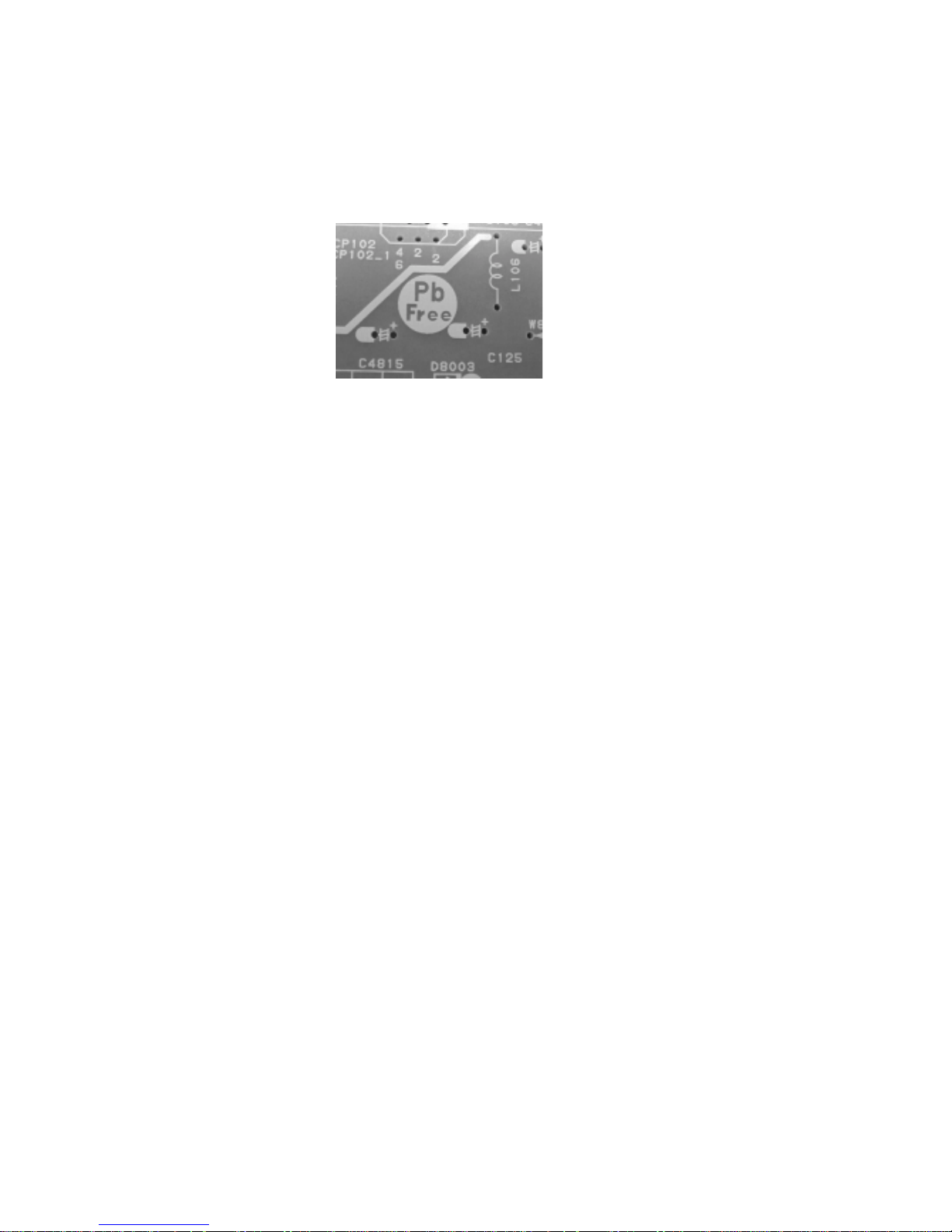
ABOUT LEAD FREE SOLDER (PbF)
Distinction of PbF PCB:
PCBs (manufactured) using lead free solder will have a PbF printing on the PCB.
(Please refer to figures.)
Caution:
Pb free solder has a higher melting point than standard solder;
•
Typically the melting point is 50°F~70°F(30°C~40°C) higher.
Please use a soldering iron with temperature control and adjust it to 650°F ± 20°F (350°C ± 10°C).
In case of using high temperature soldering iron, please be carefull not to heat too long.
Pb free solder will tend to splash when heated too high (about 1100°F/ 600°C).
•
All products with the printed circuit board with PbF printing must be serviced with lead free solder.
•
When soldering or unsoldering, completely remove all of the solder from the pins or solder area,
and be sure to heat the soldering points with the lead free solder until it melts sufficiently.
Recommendations
Recommended lead free solder composition is Sn-3.0Ag-0.5Cu.
A1-2
26HF84A

TABLE OF CONTENTS
SERVICING NOTICES ON CHECKING.....................................................................................
HOW TO ORDER PARTS ..........................................................................................................
IMPORTANT ...............................................................................................................................
ABOUT LEAD FREE SOLDER (PbF)........................................................................................
TABLE OF CONTENTS..............................................................................................................
GENERAL SPECIFICATIONS ...................................................................................................
DISASSEMBLY INSTRUCTIONS
1. REMOVAL OF ANODE CAP ...............................................................................................
2. REMOVAL AND INSTALLATION OF FLAT PACKAGE IC ................................................
SERVICE MODE LIST ................................................................................................................
CONFIRMATION OF HOURS USED .........................................................................................
WHEN REPLACING EEPROM (MEMORY) IC ..........................................................................
ELECTRICAL ADJUSTMENTS..................................................................................................
BLOCK DIAGRAMS
TV.............................................................................................................................................
SOUND AMP/FRONT JACK ...................................................................................................
MICON1/STEREO ...................................................................................................................
AV/SYNC COUNT ...................................................................................................................
INTERFACE.............................................................................................................................
MICON2 ...................................................................................................................................
SCALER ..................................................................................................................................
PRINTED CIRCUIT BOARDS
MAIN ........................................................................................................................................
AV ............................................................................................................................................
HD-MI/FRONT JACK...............................................................................................................
CRT/VM COIL/SCALER ..........................................................................................................
SCHEMATIC DIAGRAMS
CHROMA/PROGRESSIVE/PIN CUSHION ............................................................................
DEFLECTION ..........................................................................................................................
TV POWER..............................................................................................................................
OPERATION............................................................................................................................
SOUND AMP/FRONT AV........................................................................................................
MICON1 ...................................................................................................................................
STEREO ..................................................................................................................................
TUNER/AV...............................................................................................................................
REGURATOR ..........................................................................................................................
SYNC COUNT .........................................................................................................................
CRT/SVM.................................................................................................................................
INTERFACE.............................................................................................................................
MICON2 ...................................................................................................................................
ANALOG/DIGITAL CONVERTER...........................................................................................
SCALER ..................................................................................................................................
DIGITAL COMB.......................................................................................................................
SDRAM....................................................................................................................................
IO/REGULATOR .....................................................................................................................
WAVEFORMS .............................................................................................................................
MECHANICAL EXPLODED VIEWS...........................................................................................
MECHANICAL REPLACEMENT PARTS LIST .........................................................................
ELECTRICAL REPLACEMENT PARTS LIST...........................................................................
A1-1
A1-1
A1-1
A1-2
A2-1
A3-1~A3-12
B1-1
B2-1, B2-2
C-1
C-1
C-2, C-3
D-1~D-6
E-1, E-2
E-3, E-4
E-5, E-6
E-7, E-8
E-9, E-10
E-11, E-12
E-13, E-14
F-1~F-4
F-5, F-6
F-7, F-8
F-9, F-10
G-1, G-2
G-3, G-4
G-5, G-6
G-7, G-8
G-9, G-10
G-11, G-12
G-13, G-14
G-15, G-16
G-17, G-18
G-19, G-20
G-21, G-22
G-23, G-24
G-25, G-26
G-27, G-28
G-29, G-30
G-31, G-32
G-33, G-34
G-35, G-36
H-1~H-4
I-1~I-4
J1-1, J1-2
J2-1~J2-18
A2-1
26HF84A
GENERAL SPECIFICATIONS
G-1 TV CRT CRT Size / Visual Size 26 inch / 656.7mmV
System CRT Type Flat (16:9)
Color System NTSC
Speaker 2 Speaker
Sound Output MAX
NTSC3.58+4.43 /PAL60Hz No
G-2 Tuning Broadcasting System US System M
System Tuner and System 1Tuner
Receive CH Destination USA(W/ CABLE)
Intermediate Picture(FP) 45.75MHz
Frequency Sound(FS) 41.25MHz
Preset CH No
Stereo/Dual TV Sound Yes
Tuner Sound Muting Yes
G-3 Power Power Source AC 120V AC 60Hz
Power Consumption at AC
Protector Power Fuse Yes
G-4 Regulation Safety UL/CSA
G-5 Temperature Operation +5oC ~ +40oC
G-6 Operating Humidity Less than 80% RH
Deflection 104 degree
Magnetic Field BV/BH +0.45G/0.18G
Position Front Bottom
Size 1.8 x 3.9 Inch
Impedance 8 ohm
10%(Typical)
Tuning System F-Synth
Input Impedance VHF/UHF 75 ohm
CH Coverage A - I, J - W, W+1 - W+84
FP-FS 4.50MHz
DC
Stand by (at AC) 1 W at AC 120 V 60 Hz
Per Year -- kWh/Year
Safety Circuit Yes
IC Protector(Micro Fuse) Yes
Radiation FCC/IC
X-Radiation DHHS/HWC
Storage -20oC ~ +60oC
5.0W+5.0W
-W
2 - 69, 4A, A-5 - A-1,
175 W at AC 120 V 60 Hz
A3-1 26HF84A(FOR USA)
GENERAL SPECIFICATIONS
G-7 On Screen Menu Yes
Display Menu Type Icon
Picture Yes
Audio Yes
Setup Yes
Option
Locks
Control Level Yes
Stereo, SAP, Mono Yes
Video Yes
Color Stream(Component) Yes
HDMI Yes
Channel(TV/Cable) Yes
CH Label Yes
Video Label Yes
Clock Yes
Game Timer Yes
Front Panel Lock Yes
On Timer Yes
Sleep Timer Yes
Reset Yes
Sound Mute Yes
V-chip Rating Yes
NOT AVAILABLE Yes
Picture Size Yes
Mode(Picture preference) Yes
Brightness Yes
Contrast Yes
Color Yes
Tint Yes
Sharpness Yes
Color Temperature Yes
Display Format Yes
Cable Clear Yes
SVM Yes
Reset Yes
MTS Yes
Bass Yes
Treble Yes
Balance Yes
Stable Sound Yes
Speakers On/Off Yes
Dolby Virtual No
WOW SRS 3D Yes
WOW Focus Yes
WOW Tru Bass Yes
BBE No
HDMI1 Yes
HDMI2 No
Reset Yes
Language Yes
Clock Set Yes
TV/CABLE Yes
CH Program Yes
Add/ Erase Yes
Closed Caption Yes
Picture Size Yes
Picture Scroll Yes
Cinema Mode Yes
Aspect Yes
Image Tilt Yes
Yes
Timer Yes
Favorite CH Yes
CH Label Yes
VIDEO Label Yes
Yes
V-Chip Yes
Lock Yes
New Password Yes
Front Panel Lock Yes
Volume Yes
Contrast Yes
Brightness Yes
Color Yes
Tint Yes
Sharpness Yes
Bass Yes
Treble Yes
Balance Yes
Image Tilt Yes
Picture Scroll Yes
A3-2 26HF84A(FOR USA)
GENERAL SPECIFICATIONS
G-8 OSD Language English French Spanish
G-9 Clock and Sleep Timer Max Time 120 Min
Timer Step 10 Min
G-10 Remote Unit RC-GR
Control Glow in Dark Remocon No
On Timer Program Yes
Wake Up Timer No
Timer Back-up (at Power Off Mode) more than -- Min Sec
Back Light Remocon Yes
Format Toshiba
Custom Code TV:40-BFh
Power Source Voltage(D.C) 3V
Total Keys
Keys Power Yes
Multi Brand Keys TV/CBL/SAT/VCR/DVD Yes
(DVD Keys) Enter Yes
(TV / DVD Keys) SLEEP/TOP MENU Yes
(DVD / VCR Keys) Pause/Still Yes
(VCR Keys) Rec Yes
UM size x pcs UM-3 x 2 pcs
40 Keys
1 Yes
2 Yes
3 Yes
4 Yes
5 Yes
6 Yes
7 Yes
8 Yes
9 Yes
0 Yes
100 /+10 Yes
CH Up Yes
CH Down Yes
Volume Up Yes
Volume Down Yes
TV/Video(Input Select) Yes
ENT,CH RTN(Quick View) Yes
Menu > / FAV Up Yes
Menu < / FAV Down Yes
Menu Up Yes
Menu Down Yes
Mute Yes
PIC SIZE (16:9) Yes
Light Yes
RECALL(Call) / (Display) Yes
Menu/Enter / DVD MENU Yes
Exit / DVD CLEAR Yes
FF Yes
Rew Yes
Play Yes
Stop Yes
<</Skip / Search Forward Yes
>>/Skip / Search Forward Yes
TV/VCR Yes
A3-3 26HF84A(FOR USA)
GENERAL SPECIFICATIONS
G-11 Features Auto Degauss Yes
Auto Shut Off Yes
CABLE Yes
Memory(Last CH) Yes
Memory(Last Volume) Yes
V-Chip Yes
Type USA, ORION Type
SRS WOW(SRS 3D/Focus/Tru Bass) Yes
Timer(On Timer /Sleep Timer) Yes
Aspect Yes
Cinema Mode Yes
Image Tilt Yes
BBE No
Direct Input Selection Yes
Auto Search No
CH Allocation No
CH Lock Yes
CH Program Yes
CH Label Yes
SAP Yes
Just Clock Function No
VIDEO Label Yes
SVM Yes
VM Circuit Yes
Comb Filter Yes
3 -D
Super Wide Band AMP No
Cable Clear Yes
Hotel Lock No
Closed Caption Yes
Stable Sound Yes
FBT Leak Test Protect Yes
Video Lock Yes
Game Timer(Max Time:120Min) Yes
Energy Star Yes
Favorite CH Yes
Variable Audio Out Yes
Virtual Dolby No
Picture Size Yes
Color Temperature Control Yes
Mode(Picture Preference) Yes
Front Panel Lock Yes
Available Scan Rates (Component/HDMI) 480i/480p/720p/1080i
Menu=Volume Up+Volume Down Yes
Auto Setup(Language/CH Program) Yes
A3-4 26HF84A(FOR USA)

GENERAL SPECIFICATIONS
G-12 Accessories Owner's Manual Language English
Remote Control Unit Yes
Rod Antenna
Loop Antenna
U/V Mixer
DC Car Cord (Center+)
Guarantee Card
Warning Sheet
Circuit Diagram
Antenna Change Plug
Service Station List
Important Safety Instruction
Dew/AHC Caution Sheet
AC Plug Adapter
Quick Set-up Sheet
Battery Yes
AC Cord
AV Cord (2Pin-1Pin)
Registration Card (NDL Card) Yes
PTB Sheet
ESP Card
300 ohm to 75 ohm Antenna Adapter
Information Sheet(for HDMI) Yes
G-13 Interface Switch Front Power Yes
Rear AC/DC No
Indicator Power Yes(RED)
Terminals Front Video Input = VIDEO3
Rear Video Input(Rear1) = VIDEO1
G-14 Set Size Approx. W x D x H (mm)
G-15 Weight Net (Approx.) 36.0 kg
W/ Warranty Yes
Poles
Terminal
Terminal -
UM size x pcs UM-3 x 2
OEM Brand
Channel Up/Menu Up Yes
Channel Down/Menu Down Yes
Volume Up/Menu > Yes
Volume Down/Menu < Yes
TV/CABLE Selector No
Degauss No
Main Power SW No
Stand-by No
On Timer No
Audio Input = VIDEO3
S Input = VIDEO3 Yes
Other Terminal No
Video Input(Rear2) = VIDEO2
S Input = VIDEO1
S Input = VIDEO2
Audio Input(Rear1) = VIDEO1
Audio Input(Rear2) = VIDEO2
Video Output
Audio Output
Component Input1(w/ Analog Audio L/R)
Component Input2(w/ Analog Audio L/R)
HDMI Input1(w/ Analog Audio L/R)
HDMI Input2(w/ Analog Audio L/R) No
Diversity No
Ext Speaker No
VHF/UHF Antenna Input
AC Outlet No
Gross (Approx.) 41.5kg
RCA
RCA x 2
RCA
RCA
Yes
Yes
RCA x 2
RCA x 2
RCA
RCA x 2 (Variable)
RCA x 5
RCA x 5
HDMI x 1(RCA x 2)
F Type
700 x 502 x 495.5
No
No
No
No
No
No
No
No
No
No
No
No
No
No
No
No
No
No
No
( 79.4 lbs)
( 91.5lbs)
A3-5 26HF84A(FOR USA)
GENERAL SPECIFICATIONS
G-16 Carton Master Carton
Gift Box Yes
Drop Test
Container Stuffing
G-17 Cabinet Material Cabinet Cabinet Front PS 94V0 DECABROM
PCB Non-Halogen Demand
G-18 Environment Pb Free Pb-free Solder Yes
Cd Free
Content ---Material --
Dimensions W x D x H(mm)
Description of Origin
Material Double/Brown
Dimensions W x D x H(mm)
Design As per Buyer's
Description of Origin Yes
Height (cm) 60 (ORION SPEC:31)
Cabinet Rear PS 94V0 NON-DECABROM
Eyelet Demand Yes
Other
-- x -- x --
840 x 620 x 627
Natural Dropping At 1 Corner / 2 Edges
156
No
Sets
/--
No
/ 4 Surfaces
Sets/40' container
No
No
No
A3-6 26HF84A(FOR USA)

GENERAL SPECIFICATIONS
G-1 TV CRT CRT Size / Visual Size 26 inch / 656.7mmV
System CRT Type Flat (16:9)
Color System NTSC
Speaker 2 Speaker
Sound Output MAX
NTSC3.58+4.43 /PAL60Hz No
G-2 Tuning Broadcasting System US System M
System Tuner and System 1Tuner
Receive CH Destination USA(W/ CABLE)
Intermediate Picture(FP) 45.75MHz
Frequency Sound(FS) 41.25MHz
Preset CH No
Stereo/Dual TV Sound Yes
Tuner Sound Muting Yes
G-3 Power Power Source AC 120V AC 60Hz
Power Consumption at AC
Protector Power Fuse Yes
G-4 Regulation Safety UL/CSA
G-5 Temperature Operation +5oC ~ +40oC
G-6 Operating Humidity Less than 80% RH
Deflection 104 degree
Magnetic Field BV/BH +0.45G/0.18G
Position Front Bottom
Size 1.8 x 3.9 Inch
Impedance 8 ohm
10%(Typical)
Tuning System F-Synth
Input Impedance VHF/UHF 75 ohm
CH Coverage A - I, J - W, W+1 - W+84
FP-FS 4.50MHz
DC
Stand by (at AC) 1 W at AC 120 V 60 Hz
Per Year -- kWh/Year
Safety Circuit Yes
IC Protector(Micro Fuse) Yes
Radiation FCC/IC
X-Radiation DHHS/HWC
Storage -20oC ~ +60oC
5.0W+5.0W
-W
2 - 69, 4A, A-5 - A-1,
175 W at AC 120 V 60 Hz
A3-7 26HF84A(FOR CANADA)
GENERAL SPECIFICATIONS
G-7 On Screen Menu Yes
Display Menu Type Icon
Picture Yes
Audio Yes
Setup Yes
Option
Locks
Control Level Yes
Stereo, SAP, Mono Yes
Video Yes
Color Stream(Component) Yes
HDMI Yes
Channel(TV/Cable) Yes
CH Label Yes
Video Label Yes
Clock Yes
Game Timer Yes
Front Panel Lock Yes
On Timer Yes
Sleep Timer Yes
Reset Yes
Sound Mute Yes
V-chip Rating No
NOT AVAILABLE Yes
Picture Size Yes
Mode(Picture preference) Yes
Brightness Yes
Contrast Yes
Color Yes
Tint Yes
Sharpness Yes
Color Temperature Yes
Display Format Yes
Cable Clear Yes
SVM Yes
Reset Yes
MTS Yes
Bass Yes
Treble Yes
Balance Yes
Stable Sound Yes
Speakers On/Off Yes
Dolby Virtual No
WOW SRS 3D Yes
WOW Focus Yes
WOW Tru Bass Yes
BBE No
HDMI1 Yes
HDMI2 No
Reset Yes
Language Yes
Clock Set Yes
TV/CABLE Yes
CH Program Yes
Add/ Erase Yes
Closed Caption Yes
Picture Size Yes
Picture Scroll Yes
Cinema Mode Yes
Aspect Yes
Image Tilt Yes
Yes
Timer Yes
Favorite CH Yes
CH Label Yes
VIDEO Label Yes
Yes
V-Chip No
Lock Yes
New Password Yes
Front Panel Lock Yes
Volume Yes
Contrast Yes
Brightness Yes
Color Yes
Tint Yes
Sharpness Yes
Bass Yes
Treble Yes
Balance Yes
Image Tilt Yes
Picture Scroll Yes
A3-8 26HF84A(FOR CANADA)

GENERAL SPECIFICATIONS
G-8 OSD Language English French Spanish
G-9 Clock and Sleep Timer Max Time 120 Min
Timer Step 10 Min
G-10 Remote Unit RC-GR
Control Glow in Dark Remocon No
On Timer Program Yes
Wake Up Timer No
Timer Back-up (at Power Off Mode) more than -- Min Sec
Back Light Remocon Yes
Format Toshiba
Custom Code TV:40-BFh
Power Source Voltage(D.C) 3V
Total Keys
Keys Power Yes
Multi Brand Keys TV/CBL/SAT/VCR/DVD Yes
(DVD Keys) Enter Yes
(TV / DVD Keys) SLEEP/TOP MENU Yes
(DVD / VCR Keys) Pause/Still Yes
(VCR Keys) Rec Yes
UM size x pcs UM-3 x 2 pcs
40 Keys
1 Yes
2 Yes
3 Yes
4 Yes
5 Yes
6 Yes
7 Yes
8 Yes
9 Yes
0 Yes
100 /+10 Yes
CH Up Yes
CH Down Yes
Volume Up Yes
Volume Down Yes
TV/Video(Input Select) Yes
ENT,CH RTN(Quick View) Yes
Menu > / FAV Up Yes
Menu < / FAV Down Yes
Menu Up Yes
Menu Down Yes
Mute Yes
PIC SIZE (16:9) Yes
Light Yes
RECALL(Call) / (Display) Yes
Menu/Enter / DVD MENU Yes
Exit / DVD CLEAR Yes
FF Yes
Rew Yes
Play Yes
Stop Yes
<</Skip / Search Forward Yes
>>/Skip / Search Forward Yes
TV/VCR Yes
A3-9 26HF84A(FOR CANADA)
GENERAL SPECIFICATIONS
G-11 Features Auto Degauss Yes
Auto Shut Off Yes
CABLE Yes
Memory(Last CH) Yes
Memory(Last Volume) Yes
V-Chip No
Type
SRS WOW(SRS 3D/Focus/Tru Bass) Yes
Timer(On Timer /Sleep Timer) Yes
Aspect Yes
Cinema Mode Yes
Image Tilt Yes
BBE No
Direct Input Selection Yes
Auto Search No
CH Allocation No
CH Lock Yes
CH Program Yes
CH Label Yes
SAP Yes
Just Clock Function No
VIDEO Label Yes
SVM Yes
VM Circuit Yes
Comb Filter Yes
3 -D
Super Wide Band AMP No
Cable Clear Yes
Hotel Lock No
Closed Caption Yes
Stable Sound Yes
FBT Leak Test Protect Yes
Video Lock Yes
Game Timer(Max Time:120Min) Yes
Energy Star Yes
Favorite CH Yes
Variable Audio Out Yes
Virtual Dolby No
Picture Size Yes
Color Temperature Control Yes
Mode(Picture Preference) Yes
Front Panel Lock Yes
Available Scan Rates (Component/HDMI) 480i/480p/720p/1080i
Menu=Volume Up+Volume Down Yes
Auto Setup(Language/CH Program) Yes
A3-10 26HF84A(FOR CANADA)
GENERAL SPECIFICATIONS
G-12 Accessories Owner's Manual Language English / French
Remote Control Unit Yes
Rod Antenna
Loop Antenna
U/V Mixer
DC Car Cord (Center+)
Guarantee Card
Warning Sheet
Circuit Diagram
Antenna Change Plug
Service Station List
Important Safety Instruction
Dew/AHC Caution Sheet
AC Plug Adapter
Quick Set-up Sheet
Battery Yes
AC Cord
AV Cord (2Pin-1Pin)
Registration Card (NDL Card)
PTB Sheet
ESP Card
300 ohm to 75 ohm Antenna Adapter
Information Sheet(for HDMI) Yes
G-13 Interface Switch Front Power Yes
Rear AC/DC No
Indicator Power Yes(RED)
Terminals Front Video Input = VIDEO3
Rear Video Input(Rear1) = VIDEO1
G-14 Set Size Approx. W x D x H (mm)
W/ Warranty Yes
Poles
Terminal
Terminal -
UM size x pcs UM-3 x 2
OEM Brand
Channel Up/Menu Up Yes
Channel Down/Menu Down Yes
Volume Up/Menu > Yes
Volume Down/Menu < Yes
TV/CABLE Selector No
Degauss No
Main Power SW No
Stand-by No
On Timer No
Audio Input = VIDEO3
S Input = VIDEO3 Yes
Other Terminal No
Video Input(Rear2) = VIDEO2
S Input = VIDEO1
S Input = VIDEO2
Audio Input(Rear1) = VIDEO1
Audio Input(Rear2) = VIDEO2
Video Output
Audio Output
Component Input1(w/ Analog Audio L/R)
Component Input2(w/ Analog Audio L/R)
HDMI Input1(w/ Analog Audio L/R)
HDMI Input2(w/ Analog Audio L/R) No
Diversity No
Ext Speaker No
VHF/UHF Antenna Input
AC Outlet No
RCA
RCA x 2
RCA
RCA
Yes
Yes
RCA x 2
RCA x 2
RCA
RCA x 2 (Variable)
RCA x 5
RCA x 5
HDMI x 1(RCA x 2)
F Type
700 x 502 x 495.5
No
No
No
No
No
No
No
No
No
No
No
No
No
No
No
No
No
No
No
No
A3-11 26HF84A(FOR CANADA)
GENERAL SPECIFICATIONS
G-15 Weight Net (Approx.) 36.0 kg
G-16 Carton Master Carton
Gift Box Yes
Drop Test
Container Stuffing
G-17 Cabinet Material Cabinet Cabinet Front PS 94V0 DECABROM
PCB Non-Halogen Demand
G-18 Environment Pb Free Pb-free Solder Yes
Cd Free
Gross (Approx.) 41.5kg
Content ---Material --
Dimensions W x D x H(mm) -- x -- x --
Description of Origin
Material Double/Brown
Dimensions W x D x H(mm) 840 x 620 x 627
Design As per Buyer's
Description of Origin Yes
Natural Dropping At 1 Corner / 2 Edges / 4
Height (cm) 60 (ORION SPEC:31)
156
Cabinet Rear PS 94V0 NON-DECABROM
Eyelet Demand Yes
Other
( 79.4 lbs)
( 91.5lbs)
No
Sets
/--
No
Surfaces
Sets/40' container
No
No
No
A3-12 26HF84A(FOR CANADA)
DISASSEMBLY INSTRUCTIONS
1. REMOVAL OF ANODE CAP
Read the following NOTED items before starting work.
*
After turning the power off there might still be a potential
voltage that is very dangerous. When removing the
Anode Cap, make sure to discharge the Anode Cap's
potential voltage.
*
Do not use pliers to loosen or tighten the Anode Cap
terminal, this may cause the spring to be damaged.
REMOVAL
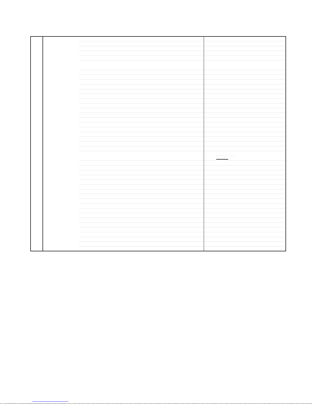
1. Follow the steps as follows to discharge the Anode Cap.
(Refer to Fig. 1-1.)
Connect one end of an Alligator Clip to the metal part of a
flat-blade screwdriver and the other end to ground.
While holding the plastic part of the insulated Screwdriver,
touch the support of the Anode with the tip of the
Screwdriver.
A cracking noise will be heard as the voltage is discharged.
GND on the CRT
3. After one side is removed, pull in the opposite direction to
remove the other.
NOTE
Take care not to damage the Rubber Cap.
INSTALLATION
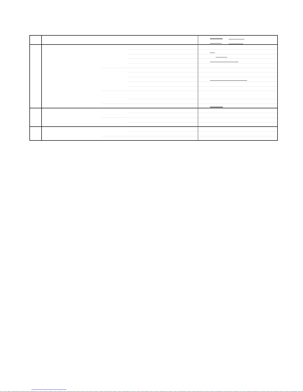
1. Clean the spot where the cap was located with a small
amount of alcohol. (Refer to Fig. 1-3.)
Location of Anode Cap
Fig. 1-3
NOTE
Confirm that there is no dirt, dust, etc. at the spot where
the cap was located.
2.3.Arrange the wire of the Anode Cap and make sure the
wire is not twisted.
Turn over the Rubber Cap. (Refer to Fig. 1-4.)
Screwdriver
Alligator Clip
GND on the CRT
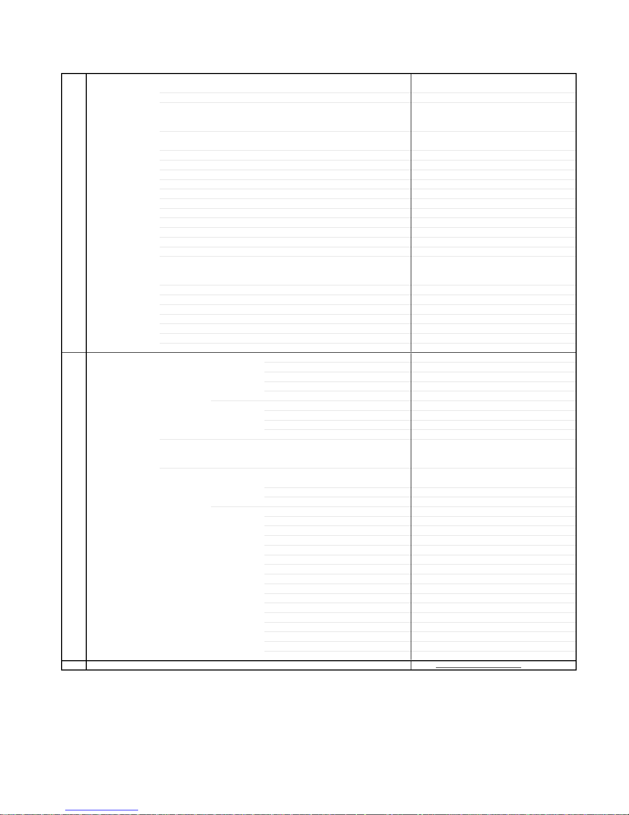
Flip up the sides of the Rubber Cap in the direction of the
2.
arrow and remove one side of the support.
(Refer to Fig. 1-2.)
Rubber Cap
CRT
Support
Support
CRT
Fig. 1-1
Fig. 1-2
Fig. 1-4
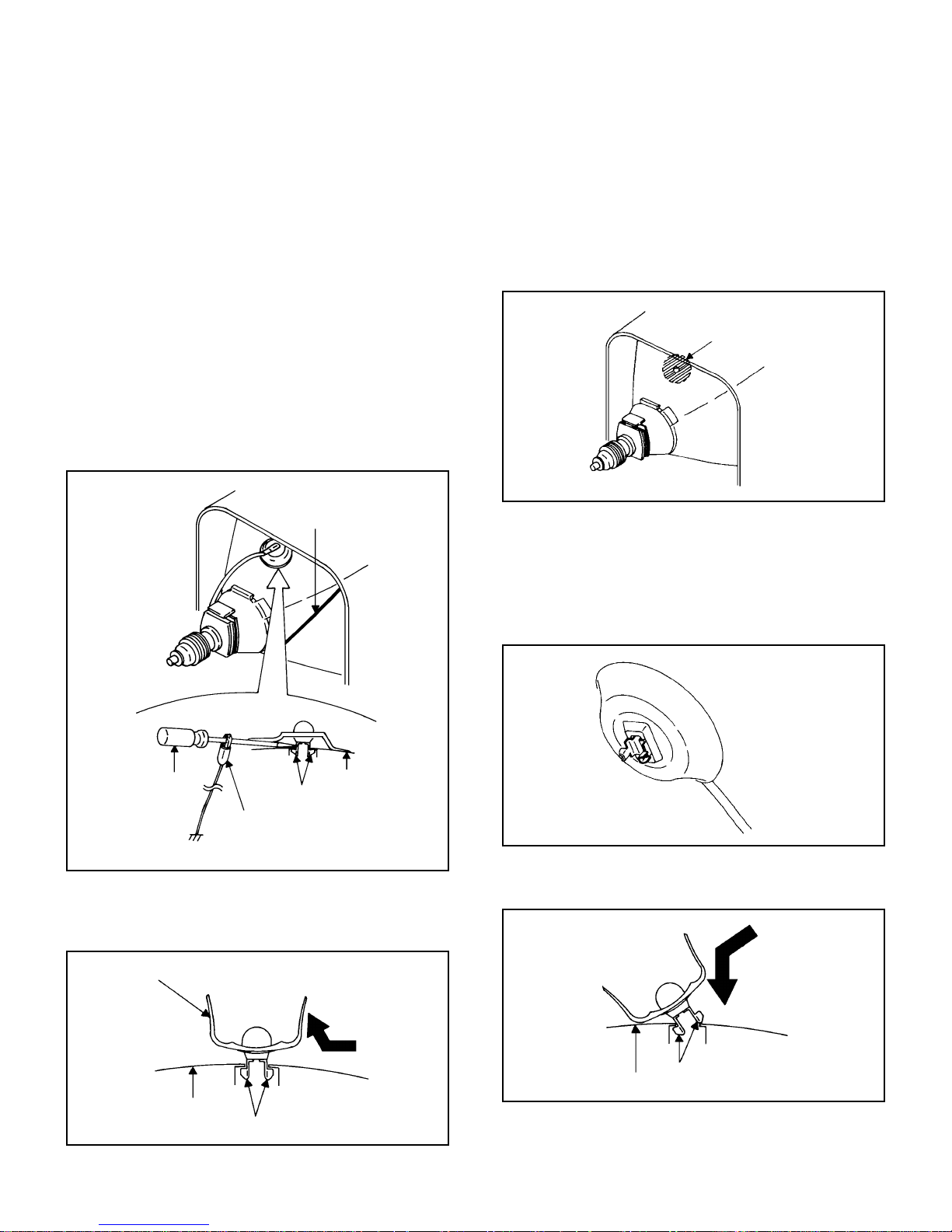
4. Insert one end of the Anode Support into the anode button,
then the other as shown in Fig. 1-5.
Support
CRT
5.6.Confirm that the Support is securely connected.
Put on the Rubber Cap without moving any parts.
B1-1 26HF84A
Fig. 1-5
DISASSEMBLY INSTRUCTIONS
2.
REMOVAL AND INSTALLATION OF
FLAT PACKAGE IC
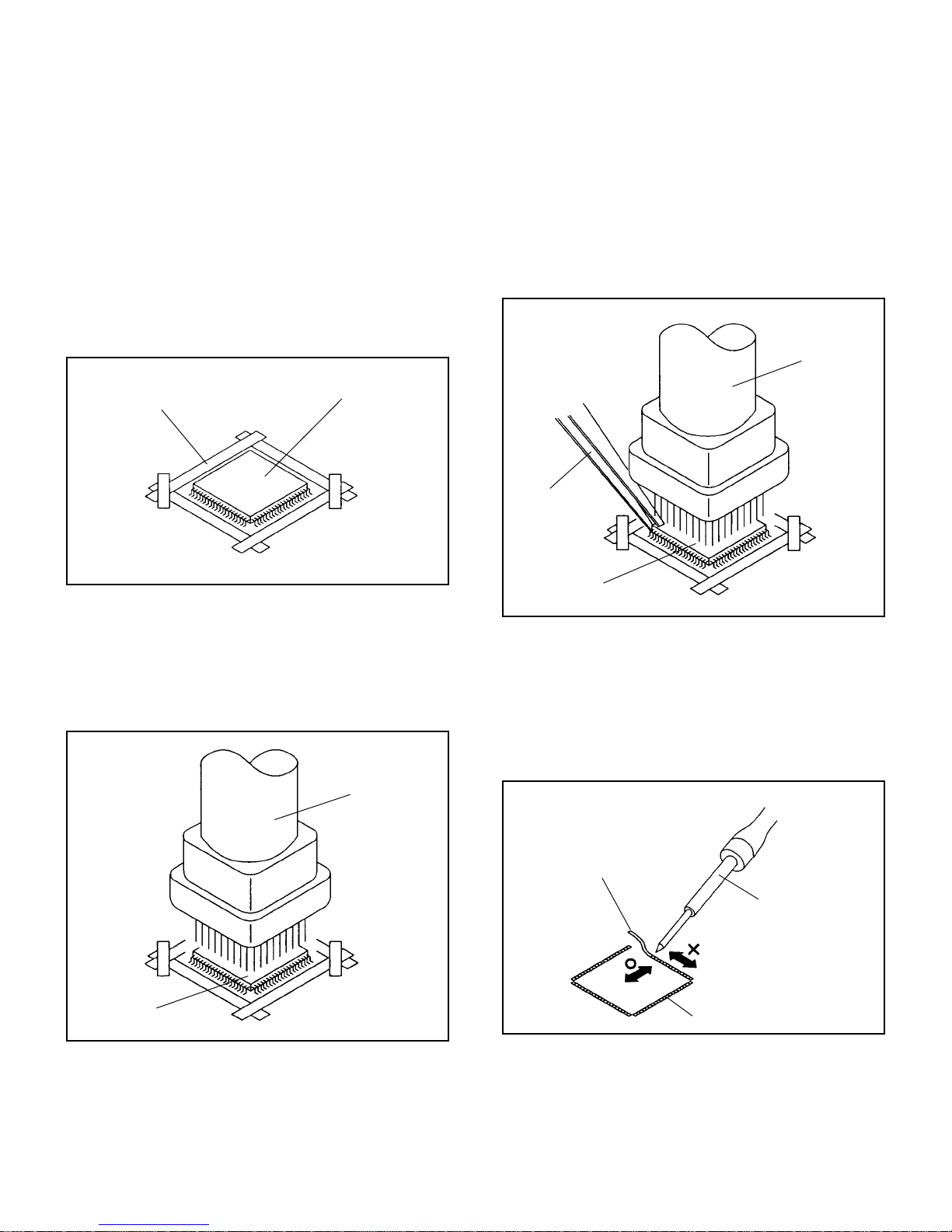
REMOVAL
Put the Masking Tape (cotton tape) around the Flat
1.
Package IC to protect other parts from any damage.
(Refer to Fig. 2-1.)
NOTE
Masking is carried out on all the parts located within 10
mm distance from IC leads.
When IC starts moving back and forth easily after
3.
desoldering completely, pickup the corner of the IC using a
tweezers and remove the IC by moving with the IC
desoldering machine. (Refer to Fig. 2-3.)
NOTE
Some ICs on the PCB are affixed with glue, so be
careful not to break or damage the foil of each IC leads
or solder lands under the IC when removing it.
Blower type IC
desoldering
machine
Masking Tape
(Cotton Tape)
Heat the IC leads using a blower type IC desoldering
2.
IC
machine. (Refer to Fig. 2-2.)
NOTE
Do not add the rotating and the back and forth
directions force on the IC, until IC can move back and
forth easily after desoldering the IC leads completely.
Blower type IC
desoldering machine
Fig. 2-1
Tweezers
IC
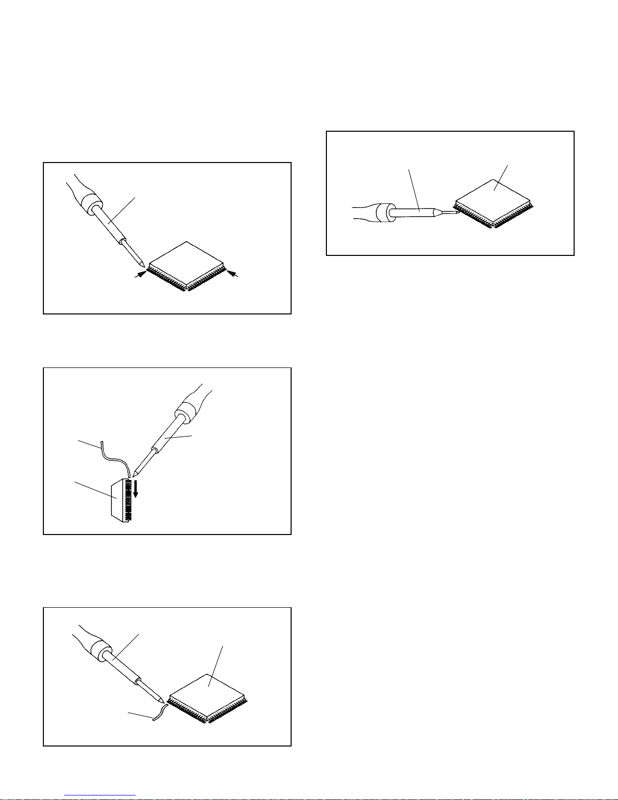
Peel off the Masking Tape.4.
Absorb the solder left on the pattern using the Braided
5.
Shield Wire. (Refer to Fig. 2-4.)
NOTE
Do not move the Braided Shield Wire in the vertical
direction towards the IC pattern.
Fig. 2-3
IC
Fig. 2-2
Braided Shield Wire
Soldering Iron
IC pattern
Fig. 2-4
B2-1 26HF84A
DISASSEMBLY INSTRUCTIONS
INSTALLATION
Take care of the polarity of new IC and then install the new
1.
IC fitting on the printed circuit pattern. Then solder each
lead on the diagonal positions of IC temporarily.
(Refer to Fig. 2-5.)
Soldering Iron
Solder temporarily
Supply the solder from the upper position of IC leads
2.
sliding to the lower position of the IC leads.
(Refer to Fig. 2-6.)
Solder temporarily
Fig. 2-5
When bridge-soldering between terminals and/or the
4.
soldering amount are not enough, resolder using a Thin-tip
Soldering Iron. (Refer to Fig. 2-8.)
Thin-tip Soldering Iron
IC
Fig. 2-8
Finally, confirm the soldering status on four sides of the IC
5.
using a magnifying glass.
Confirm that no abnormality is found on the soldering
position and installation position of the parts around the IC.
If some abnormality is found, correct by resoldering.
NOTE
When the IC leads are bent during soldering and/or
repairing, do not repair the bending of leads. If the
bending of leads are repaired, the pattern may be
damaged. So, always be sure to replace the IC in this
case.
Soldering IronSolder
IC
Supply soldering
from upper position
to lower position
Fig. 2-6
Absorb the solder left on the lead using the Braided Shield
3.
Wire. (Refer to Fig. 2-7.)
NOTE
Do not absorb the solder to excess.
Soldering Iron
IC
Braided Shield Wire
Fig. 2-7
B2-2 26HF84A
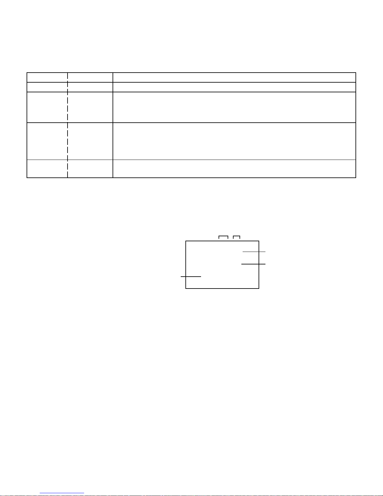
SERVICE MODE LIST
This unit provided with the following SERVICE MODES so you can repair, examine and adjust easily.
To enter the Service Mode, press both set key and remote control key for more than 2 seconds.
Set Key
VOL. (-) MIN
Remocon Key
0
Releasing of V-CHIP PASSWORD.
Operations
Initialization of the factory.
VOL. (-) MIN
1
NOTE:
Do not use this for the normal servicing.
If you set a factory initialization, the memories are reset such as the channel setting,
and the POWER ON total hours.
POWER ON total hours is displayed on the screen.
Refer to the "CONFIRMATION OF HOURS USED".
VOL. (-) MIN
6
Can be checked of the INITIAL DATA of MEMORY IC.
Refer to the "WHEN REPLACING EEPROM (MEMORY) IC".
VOL. (-) MIN
9
Display of the Adjustment MENU on the screen.
Refer to the "ELECTRICAL ADJUSTMENT" (On-Screen Display Adjustment).
CONFIRMATION OF HOURS USED
POWER ON total hours can be checked on the screen. Total hours are displayed in 16 system of notation.
NOTE: If you set a factory initialization, the total hours is reset to "0".
1.
Set the VOLUME to minimum.
2.
Press both VOL. DOWN button on the set and Channel
button (6) on the remote control for more than 2 seconds.
3.
After the confirmation of using hours, turn off the power.
MICON Version
ADDRESS DATA
INIT 000 DF
CRT ON 0010
OEC7118A_32
FIG. 1
Initial setting content of MEMORY IC.
POWER ON total hours.
= (16 x 16 x 16 x thousands digit value)
+ (16 x 16 x hundreds digit value)
+ (16 x tens digit value)
+ (ones digit value)
C-1 26HF84A
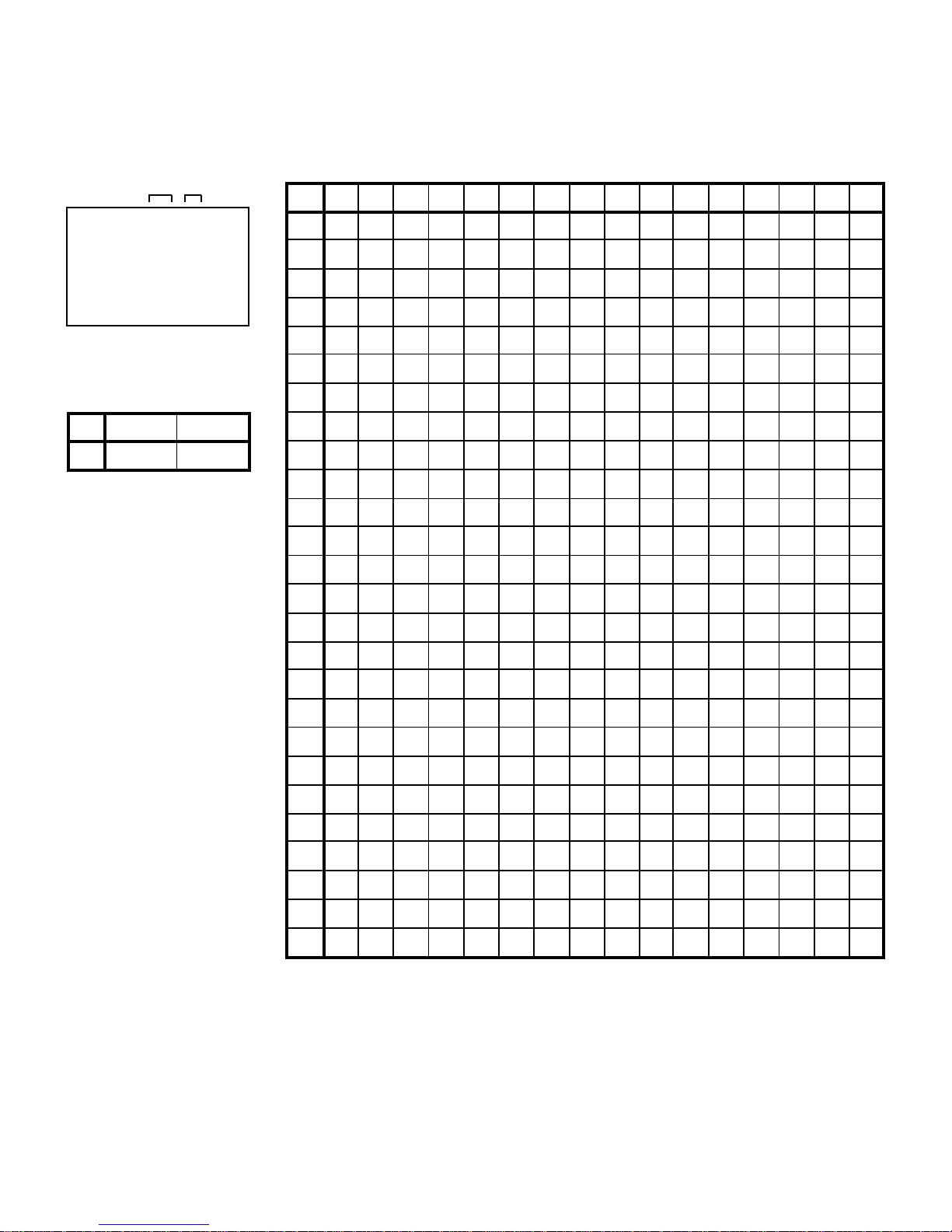
WHEN REPLACING EEPROM (MEMORY) IC
If a service repair is undertaken where it has been required to change the MEMORY IC, the following steps should be taken to
ensure correct data settings while making reference to TABLE 1.
ADDRESS DATA
+0 +1 +2 +3 +4 +5 +6 +7 +8 +9
+A
+B +C +D +E +FINI
*1
INI
000
INIT 000 DF
CRT ON 0010
OEC7118A_32
FIG. 1
USA CANADA
DF 5F
*1 A2 05 C0 A6 1C 87 B8 42 E4
05
01 1F 24 40 45 5D 62 45 4A
10
20 00 5A 98 33 04 76
84 00 00 00 00 00 00 00 00 1A
30 01 07 06 40 40 40
77 05 07 21 10 07 00 22 74 81
40 C0 00 51 70 72 99 59
8F 40 00 27 0A 0A 00 13 40
68 5B 00 73 14 1F 2D 24 16
50
60 09 00 C9 C8 E8 BC
70
80 96 8B 2C 90 22 00
90 33 23 27 2A 2D 30
A0 36 51 53 55 57 58 59
B0
C0
D0 79 42 00 00 00 0B
E0 17 31 36 40 00 3F
F0 --- --- --- --- --- --- ---
99
08 D6 D9 DB 15 00 00 26 06 07
0F
40 00 4A 22 77 00 00 00 07
FF C0 52 50 8B 00 06 06 22 00
11 F2 00 07 00 00 00 B6 01 48
33 39 3C 3F 42 45 48 4B 4E
5A 5C 5D 5E 5F 61 63 65 67
5B
70
6F 71 71 72 72 73 73 74 74
76 76 77 77 77 77 78 78 78 78
15 06 11 14 E0 E6 F5 2B 38 FF
54 --- --- --- --- --- --- --- ---
B3 03 0D 36 03 0000
67 0F 15 0A 00 64
00 00 00 00 00 FE
1D 6D FF FF FA FA
69 6A 6B 6C 6D 6E
75 75 75 75 76 76
DC 54 22 66 0C 71 69 33 00
100
110 82 88 88 00 82 01
120
130 00 11 1A 00 1C 00
140 A4 03 03 00 7F 7F
F1
69 33 00 44 00 77 59 94 57 03
03
00 82 03 82 0F 85 00 82 8D
00 82 00 82 0D 00 05 11 00 11
00 00 00 00 00 25 1E F4 05 16
0E 38 22 66 DA 71
83 00 82 D0 01 82
00 7E 0E 0A 00 00 00 00 84150 7E 00 00 00 00 00 83
00 00 00 00 1D 0A FF F3 EC
160
170
180 FB 00 19 01 FB 00
190 77 77 77 --- --- ---
00
FF
FF FB 00 10 01 FB 00 20 01
2A 01 FB 00 10 01 FB 00 05 01
42 01 FB 00 27 01 FB 00 05 01
FF FF FF FF FF FF
FB 00 4D 01 FB 00
Table 1
C-2 26HF84A
 Loading...