

Toshiba UC1A1A008C6B, UC1A1A006C6B, 1400RE, 1400SE Plus, UC1A1A010C6B Operation Manual
...
TOSHIBA
UNINTERRUPTIBLE POWER SYSTEM
SINGLE PHASE - .6/.8/1.0/1.2/1.5/2.0/2.4 kVA
SINGLE PHASE - .6/.8/1.0/1.5 kVA PLUS
and
including
MANUFACTURED IN THE U.S.A.
OPERATION MANUAL
March, 2003
Part #44470-004

TOSHIBA

TOSHIBA
NOTE
The instructions contained in this manual are not intended to cover all of the details
or variations in equipment, nor to provide for every possible contingency
to be met in connection with installation, operation, or maintenance. Should further
information be desired or should particular problems arise which are not covered
sufficiently for the purchaser's purposes, the matter should be referred to the local
Toshiba sales office.
The contents of this instruction manual shall not become a part of or modify any
prior or existing agreement, commitment, or relationship. The sales contract
contains the entire obligation of Toshiba International Corporation's UPS Division.
The warranty contained in the contract between the parties is the sole warranty of
Toshiba International Corporation's UPS Division and any statements contained
herein do not create new warranties or modify the existing warranty.
Any electrical or mechanical modifications to this equipment,
without prior written consent of Toshiba International
Corporation, will void all warranties and may void UL listing
and/or CSA certification. Unauthorized modifications also
can result in personal injury, death, or destruction of the
equipment.
UNINTERRUPTIBLE POWER SUPPLY
If additional information or technical assistance is required call Toshiba's marketing
department toll free at (800) 231-1412 or write to: Toshiba International Corporation,
13131 W. Little York Road, Houston, TX 77041-9990.
Please complete the following information for your records and to remain within this
equipment manual:
Model Number:
Serial Number:
Date of Installation:
Inspected By:
i

TOSHIBA
CONTENTS
SECTION PAGE
Disclaimer .................................................................................................. i
Contents .................................................................................................. ii-iii
Introduction...............................................................................................iv
General Safety Instructions ..................................................................... v
Important Safety Instructions ............................................................... vi-vii
1.0 Product Description ................................................................................ 1-1
1.1 Theory of Operation ........................................................................ 1-1
1.2 Application and Use ........................................................................1-1
1.3 Power Backup................................................................................. 1-1
1.4 Power Conditioning......................................................................... 1-1
2.0 Inspection/Storage/Disposal ..................................................................2-1
2.1 Inspection of the new UPS equipment............................................ 2-1
2.2 Storage of UPS equipment .............................................................2-1
2.3 Disposal ..................................................................................2-1
3.0 Precautions ..................................................................................3-1
3.1 Installation Precautions (General) ..................................................3-1
3.2 Installation Precautions (Rack mounted) ........................................3-1
3.3 Prestart Precautions .......................................................................3-2
3.4 Operating Precautions ....................................................................3-2
4.0 Specifications ..................................................................................4-1
4.1 Standard Series Specifications ....................................................... 4-1
4.2 Plus Series Specifications (w/output isolation transformer) ............4-4
4.3 Standard Series Specifications (Rack mounted) ............................ 4-6
5.0 Operating the UPS ..................................................................................5-1
5.1 Operation Modes ............................................................................5-1
5.1.1 AC Input Mode (normal operation) ........................................5-1
5.1.2 Battery Backup Mode ............................................................ 5-2
5.1.3 Circuit Bypass Mode .............................................................. 5-3
5.2 System Protection Features ........................................................... 5-4
ii

TOSHIBA
CONTENTS (Cont'd)
SECTION PAGE
5.0 Operating the UPS (cont'd) ..................................................................... 5-1
5.3 Operation Monitoring ......................................................................5-5
5.3.1 Visual Indicator Functions ...................................................... 5-5
5.3.2 Audible Alarm Functions ........................................................ 5-5
5.3.3 Visual and Audible Indicator Function Chart .......................... 5-5
5.4 Front Panel Layout ......................................................................... 5-6
5.5 UPS Run Mode Display ..................................................................5-6
5.6 Battery Recharging .........................................................................5-7
5.7 Battery Backup Time ...................................................................... 5-8
5.8 Battery Low Voltage Tolerances ..................................................... 5-8
5.9 Battery Check Function .................................................................. 5-8
5.10 System Reset ................................................................................. 5-8
6.0 UPS Control Interface .............................................................................6-1
6.1 Remote Contact and IBM AS/400 ................................................... 6-1
6.2 RS-232C Communication Interface ................................................6-2
6.2.1 UPS Shutdown (via RS-232C) ............................................... 6-2
7.0 Troubleshooting Procedures..................................................................7-1
7.1 Non-Fatal Fault Mode .....................................................................7-1
7.2 Fatal Fault Mode .............................................................................7-2
8.0 Preventive Maintenance/Parts Replacement ........................................8-1
8.1 Preventive Maintenance .................................................................8-1
8.2 Parts Replacement .........................................................................8-1
8.3 Input/Output Fuse Rating Chart ...................................................... 8-1
9.0 External Dimensions/Shipping Weights/Panel Layout ........................9-1
9.1 External Dimensions for 600 through 1200 VA Model .................... 9-1
9.2 External Dimensions for 1500 through 2400 VA Model .................. 9-2
9.3 External Dimensions for 1500 through 2000 VA Model
(Rack Mounted) .............................................................................9-3
9.4 Remote Run/Stop ...........................................................................9-4
9.5 Panel Layout ..................................................................................9-5
9.6 Panel Layout (Rack Mounted) ........................................................9-5
9.7 Shipping Weights ............................................................................9-5
iii

TOSHIBA
Thank you for purchasing the 1400SE/1400SE Plus Series UPS. This Series features the very
latest state of the art microprocessor technology and also uses IGBT transistors for fast, high
power and low noise PWM (pulse width modulation) switching. Also, the Plus Series features a
low impedence output transformer to provide isolation even during bypass operation.
It is the intent of this manual to provide a guide for safely installing, operating, and maintaining
the UPS. This operation manual contains a section of general safety instructions and is marked
throughout with warning symbols. Read this operation manual thoroughly before installation
and operation of this electrical equipment.
All safety warnings must be followed to ensure personal safety.
Follow all precautions to attain proper equipment performance and longevity.
General safety instructions are found on page v and important safety
instructions are found on pages vi and vii. Read and save these instructions
for future reference.
INTRODUCTION
The manual is divided into major sections of interest. Section 1 contains the product description
with the theory of operation and applications. All of the initial inspection, storage, installation,
operating, and prestart precautions can be found in Sections 2 and 3.
Section 4 contains the equipment standard specifications.
Section 5 outlines the operating modes, protective features, battery recharging, battery low
voltage tolerances, alarm and panel indicator functions.
Section 6 shows the control interface pin configurations.
Sections 7 and 8 are devoted to troubleshooting procedures, preventative maintenance
techniques and periodic parts replacement. A fuse rating chart is also shown.
Section 9 shows front, rear, and side panel layout views with dimensional data. Labels,
connector and switch placement, and shipping weights are also shown.
We hope that you find this operation manual informative and easy to use. If additional information
or technical assistance is needed, please call toll free (800) 231-1412 or write to: Toshiba
International Corporation, 13131 W. Little York Road, Houston, TX 77041-9990.
Again, thank you for the purchase of this product.
© Copyright 1994
TOSHIBA INTERNATIONAL CORPORATION
iv
GENERAL SAFETY INSTRUCTIONS
Warnings in this manual appear in any of four ways:
1) Danger - The danger symbol is a lightning bolt mark enclosed in a triangle which precedes
the 3/16" high letters spelling the word "DANGER". The danger symbol is used to indicate
imminently hazardous situations, locations, and conditions which, if not avoided, WILL
result in death, serious injury, and/or severe property damage.
DANGER
2) Warning - The warning symbol is an exclamation mark enclosed in a triangle which
precedes the 3/16" high letters spelling the word "WARNING". The warning symbol is
used to indicate potentially hazardous situations and conditions which, if not avoided
COULD result in serious injury or death. Severe property damage COULD also occur.
WARNING
TOSHIBA
3) Caution - The caution symbol is an exclamation mark enclosed in a triangle which
precedes the 3/16" high letters spelling the word "CAUTION". The caution symbol is used
to indicate potentially hazardous situations and conditions which, if not avoided may result
in injury. Equipment damage may also occur.
CAUTION
4) Attention warnings - The attention warning symbol is an exclamation mark enclosed in a
triangle which precedes the 3/16" high letters spelling the word "ATTENTION". The
Attention warning symbol is used to indicate situations and conditions that can cause
operator injury and/or equipment damage:
ATTENTION
Other warning symbols may appear along with the Danger and Caution symbol and are used to specify
special hazards. These warnings describe particular areas where special care and/or procedures are
required in order to prevent serious injury and possible death:
1) Electrical warnings - The electrical warning symbol is a lighting bolt mark enclosed in
a triangle. The Electrical warning symbol is used to indicate high voltage locations and
conditions that may cause serious injury or death if the proper precautions are not
observed:
2) Explosion warnings - The explosion warning symbol is an explosion mark enclosed in
a triangle. The Explosion warning symbol is used to indicate locations and conditions
where molten, exploding parts may cause serious injury or death if the proper
precautions are not observed:
v

TOSHIBA
IMPORTANT SAFETY INSTRUCTIONS
SAVE THESE INSTRUCTIONS-
that should be followed during the installation and maintenance of the UPS and it's batteries. Use for
models UC1A1A006C6TB, UC1A1A006C6B, UC1A1A008C6TB, UC1AIA008C6B, UC1A1A010C6B,
UC1A1A010C6TB, UC1A1A012C6B, UC1A1A015C6B, UC1A1A015C6TB, UC1A1A020C6B,
UC1A1A024C6B, UC1A1A015C6RKB, UC1A1A015C6RKPB, and UC1A1A020C6RKB
- The maximum ambient temperature in which this UPS unit should be operated or stored is
104 deg F (40 deg C).
- The nominal battery voltage range is indicated in Section 5.6 on page 5-7.
- Servicing of the batteries should only be performed by a qualified Toshiba Representative who is
knowledgeable of batteries and the required precautions. Keep unauthorized personnel away from
batteries.
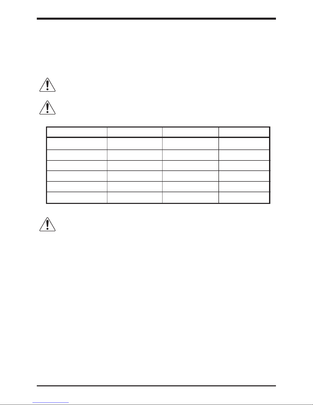
- When replacing batteries, use the same number and type of one of the following sealed, lead-acid
batteries (do not mix types of batteries):
Model Capacity Manufacturer Type Quantity
600 VA Panasonic LCV 12V7.2PI 3
Yuasa NP7 - 12FR 3
800 VA Panasonic LCV 12V7.2PI 4
Yuasa NP7 - 12FR 4
1000 VA Panasonic LCV 12V7.2PI 4
Yuasa NP7 - 12FR 4
1200 VA Panasonic LC 12V7.2PI 5
Yuasa NP7 - 12FR 5
1500 VA and Panasonic LCV 12V7.2PI 6
UC1A1A020C6RKB Yuasa NP7 - 12FR 6
2000 and 2400 VA Panasonic LCV 12V7.2PI 8
(except UC1A1A020C6RKB) Yuasa NP7 - 12FR 8
This manual contains important instructions
CAUTION
either indirect or consequential damage or injury that may result from the use of this equipment.
Misuse of this equipment could result in human injury and equipment
damage. In no event will Toshiba Corporation be responsible or liable for
CAUTION
CAUTION
Do not open or mutilate the batteries. Released electrolyte is harmful
to the eyes and skin and could also be toxic.
WARNING
flame. Annual preventative maintenance must be performed by an authorized, trained technician.
WARNING
resulting in secondary faults such as odor, smoke, and fire.
Do not dispose of the batteries in a fire. The batteries may explode.
This unit contains sealed lead acid batteries. Lack of preventative
maintenance could result in batteries exploding and emitting gasses and/or
Failure to replace a battery before it becomes exhausted may cause the
case to crack, possibly releasing electrolytes from inside the battery, and
vi
IMPORTANT SAFETY INSTRUCTIONS
TOSHIBA
WARNING
unauthorized personnel away from the batteries.
WARNING
your UPS system. Refer to service manual.
DANGER
working with batteries:
1) Verify that the UPS is off and that the power cord is disconnected from the power source.
2) Remove watches, rings or other metal objects.
3) Use tools with insulated handles to prevent inadvertent shorts.
4) Wear rubber gloves and boots.
5) Do not lay tools or metal parts on top of batteries.
6) Determine if the battery is inadvertently grounded. If inadvertently grounded, remove
source of ground. Contact with any part of a grounded battery can result in
electrical shock. The likelihood of such shock will be reduced if such grounds are
removed during installation and maintenance.
7) Verify circuit polarities prior to making connections.
8) Disconnect charging source and load prior to connecting or disconnecting terminals.
9) VRLA batteries contain an explosive mixture of hydrogen gas. Do not smoke, cause a flame
or spark in the immediate area of the batteries. This includes static electricity from the body.
10) Do not attempt to open the batteries in order to add water or sample the specific gravity of the
electrolyte. The batteries are valve regulated lead acid type and such servicing is not
possible without damaging the battery.
11) Use proper lifting means when moving batteries and wear all appropriate safety clothing and
equipment.
12) Do not dispose of lead acid batteries except through channels in accordance with local, state
and federal regulations.
Installation and servicing of batteries should be performed by personnel
knowledgeable of batteries and the required precautions. Keep
Proper maintenance to the battery system of this unit must be done by a
qualified service technician, this is essential to the safety and reliability of
A battery can present a risk of electrical shock and high short
circuit current. The following precautions should be observed when
vii
TOSHIBA
INSTRUCTIONS IMPORTANTES CONCERNANT
LA SÉCURITÉ
Cette notice contient des
CONSERVER CES INSTRUCTIONS
Une battery peut présenter un risque de choc électrique, de brûlure par
ATTENTION
ATTENTION
Model Capacity Manufacturer Type Quantity
600 VA Panasonic LCV 12V7.2PI 3
800 VA Panasonic LCV 12V7.2PI 4
1000 VA Panasonic LCV 12V7.2PI 4
1200 VA Panasonic LCV 12V7.2PI 5
1500 VA and Panasonic LCV 12V7.2PI 6
UC1A1A020C6RKB Yuasa NP7 - 12FR 6
2000 and 2400 VA Panasonic LCV 12V7.2PI 8
(except UC1A1A020C6RKB) Yuasa NP7 - 12FR 8
transfert d' énergie.
Pour le remplacement, utiliser le même nombre de batteries du modéle
suivant.
Yuasa NP7 - 12FR 3
Yuasa NP7 - 12FR 4
Yuasa NP7 - 12FR 4
Yuasa NP7 - 12FR 5
instructions importantes concernant
la sécurité.
ATTENTION
L' élimination des batteries est règlementèe. Consulter les codes locaux
à cet effet.
© Copyright 1994
viii

1.0 Product Description
1.1 Theory of Operation
An uninterruptible power supply is a system that is installed between the commercial
power and the load equipment. It is used during short-term blackouts or brownouts. The
UPS provides steady ac output power during these commercial power interruptions.
This power is provided for a long enough time so that the load can be shutdown in an
orderly fashion. This prevents loss of data and possible damage to both hardware and
software.
During normal operation the UPS uses commercial ac power. In addition, it also takes
in all of the high voltage spikes and transients caused by switching and faults, and all
of the common mode and normal mode noise which is associated with commercial ac
power. The UPS converts it all to flat dc power. From this dc power, the UPS charges
its batteries and generates its own extremely high quality ac waveform output. The
result of this process is maximum power conditioning.
If the ac power supplied to the UPS drops below a specified voltage level, the unit's
batteries automatically begin supplying power instead of receiving it. This insures that
the loads connected to the UPS continue to receive power with no interruption. When
ac input power becomes available again, operation returns to normal. The unit's
batteries begin to recharge so they will be ready for the next power interruption.
TOSHIBA
1.2 Application and Use
Toshiba's 1400SE and 1400SE Plus Series of on-line uninterruptible power supply (UPS)
systems provide continuous computer-grade ac power in a compact, high performance,
and energy efficient unit. The UPS unit assures safe and reliable operation of critical
office equipment. This can range from word processors and personal computers to
mini-computers and local area networks. All units feature an audible alarm which sounds
if the battery voltage drops below standard during use. This is an additional aid to help
in retaining the valuable office data banks. All units allow for computer interfacing and
an external battery pack option (see specifications).
1.3 Power Backup
When an electrical power failure occurs, the UPS unit's internal maintenance-free
batteries automatically supply back-up power to the load without interruption. For
example, when used to support a computer, the UPS back-up assures enough
additional time to complete the activity and store data. This allows an orderly shutdown
after a power failure has occurred.
1.4 Power Conditioning
When commercial power is present, the UPS supplies conditioned power to the load
while maintaining its batteries in a charged condition. The UPS protects against the
normal everyday problems associated with heavy use of raw commercial ac power,
including power sags, surges, signal interference, and spikes. This protection keeps
power-line problems from reaching the loads where they can cause equipment to
operate erratically, hard-disk crashes, or cause damage to hardware and software.
1 - 1

TOSHIBA
2.0 Inspection/Storage/Disposal
2.1 Inspection of the new UPS equipment
Upon receipt of the UPS, a careful inspection for shipping damage should be made.
After Uncrating:
1) Check the unit for loose, broken, bent or otherwise damaged parts. If damage
has occurred during shipment, keep all original crating and packing materials
for return to shipping agent. Warranty will not apply to units which are damaged
during shipment.
2) Check to see that the rated capacity and the model number specified on the
nameplate conform to the order specifications.
2.2 Storage of UPS equipment.
If the UPS equipment is to be subject to long or short term storage the following
guidelines should be used.
Avoid:
1) Storage in sites subject to extreme changes in temperature or high humidity.
2) Storage in sites subject to exposure of high levels of dust or metal particles
3) Storage on inclined floor surfaces or in sites subject to excessive vibration.
Before storing:
1) Charge the units batteries.
2) Place the STOP/RUN switch in the STOP position.
Storing:
1) Store within a temperature range of -20° to 40° C (-4° to 104° F).
2) For best results, store the UPS in the original shipping container and place on a
3) The optimum storage temperature is 21° C (70° F). Higher ambient
After storing:
1) If stored in an ambient temperature under 20° C (68° F); recharge the batteries
2) If stored in an ambient temperature of 20° to 30° C (68° to 86° F); recharge the
3) If stored in an ambient temperature of 30° to 40° C (86° to 104° F); recharge the
2.3 Disposal
Please contact your state environmental agency for details on disposal of electrical
components and packaging in your particular area.
wood or metal pallet.
temperatures cause UPS batteries to need recharging more frequently.
every 9 months.
batteries every 6 months.
batteries every 3 months.
It is illegal to dump lead-acid batteries in landfills or to dispose of them improperly.
Please help our Earth by contacting the environmental protection agencies in your area,
the battery manufacturer, or call Toshiba toll-free at (800) 231-1412 for more information
about recycling.
2 - 1
3.0 Precautions
3.1 Installation Precautions (General)
1) Install the unit in a well ventilated location; allow at least 10 cm (4 inches) on
2) Install the unit in a stable, level, and upright position which is free of vibration.
3) Install the unit where the ambient temperature is within the correct operating
4) Do not install the UPS in areas that are subject to high humidity.
5) Do not allow direct sunlight to shine on the unit.
6) Do not install the UPS in areas which are subject to contamination such as
7) Avoid installation near sources of electrical noise and always make sure that
TOSHIBA
CAUTION
all sides for air ventilation and for maintenance.
range (see Specifications Section 4.0).
high levels of airborne dust, metal particles, or inflammable gas.
the unit ground is intact to prevent electrical shock and to help reduce
electrical noise.
8) Do not install where water or any foreign object may get inside the UPS.
9) This UPS generates and can radiate radio-frequency energy during operation.
Although RFI noise filters are installed inside the unit there is no guarantee
that the UPS will not influence some sensitive devices which are operating
close by. If such interference is experienced, the UPS should be installed farther
away from the effected equipment and/or powered from a different source than
that of the affected equipment.
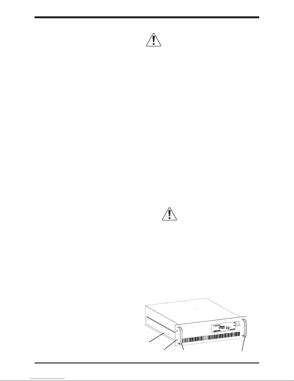
3.2 Installation Precautions (Rack mounted)
1) Install the UPS in a conventional rack-style structure. If attaching Jonathan
QD 145 slides, optional pre-tapped aluminum slide bars are available. The
optional aluminum slide bars may be attached to the sides of the unit as shown
(see detail below). The rack must be bolted to the floor, secured permanently to
a wall, or otherwise secured to prevent toppling.
2) Allow at least 4 inches of open space in the front of the unit for proper ventilation.
3) Allow at least 30 inches of open space at the rear of the unit for operation of
disconnect devices.
4) Use an appropriate mechanical lifting device when moving this unit into or out
of the rack structure.
CAUTION
Optional aluminum slide bars
(pre-tapped to accept a Jonathan
QD145 slide)
Front panel cutout
3 - 1
Use both handles when lifting
entire weight of the unit
 Loading...