

Torus Power WM 75 BAL, WM 100 BAL, WM 45 BAL TVSS, WM 60 BAL, WM 60 BAL TVSS User Manual
...Page 1
WM Series Manual
Warning:
User is responsible for installing this unit in accordance with all
local, provincial/state and federal electrical code requirements.
The installation of this unit requires inspection and approval
by local safety authority. This wall mount unit is not equipped
with a power safety interlock.
Page 2

Page 3

www.TorusPower.com
Table of Contents
Table of Contents......................................................................................................
Important Safety Instructions....................................................................................
Shipping Carton & Packing Material.............................................................................
Placement & Ventilation.............................................................................................
Torus Power WM Series Description.............................................................................
Transient Voltage Surge Suppression (TVSS)...............................................................
Power Sharing Outputs..............................................................................................
Circuit Protection......................................................................................................
Thermal Protection....................................................................................................
Circuit Schematic - North American WM Model.............................................................
Layout - North American WM Model............................................................................
Electrical Specications - North American Models..........................................................
Electrical Specications - International Models.............................................................
Mechanical Specications - North American Models.......................................................
Mechanical Specications - International Models...........................................................
Wall Cabinet External Layout - WM Series....................................................................
Warranty................................................................................................................
Page 1
Page 2
Page 2
Page 2
Page 3
Page 3
Page 3
Page 3
Page 3
Page 4
Page 5
Page 6
Page 6
Page 6
Page 6
Page 7
Page 8
Page 1
Page 4
www.TorusPower.com
Important Safety Instructions
CAUTION! To reduce the risk of electric shock and re, do not remove the cover of this device. There are no
user serviceable parts inside. Please refer all servicing to licensed service technicians.
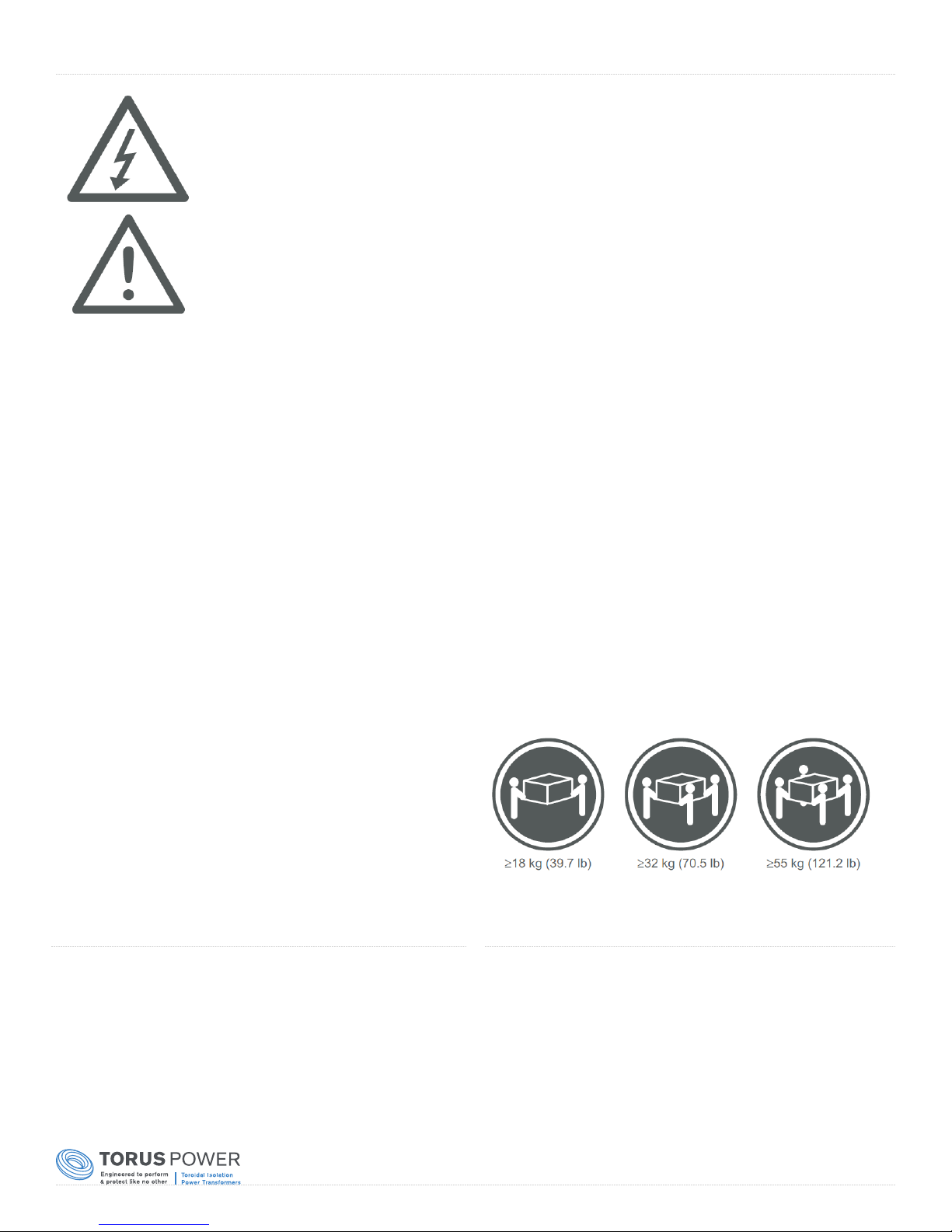
CAUTION! The international symbol of a lightning bolt inside a triangle is intended to alert the user to
uninsulated “dangerous voltage” within the device’s enclosure. The international symbol of an exclamation
point inside a triangle is intended to alert the user to the presence of important operating, maintenance and
servicing information in the manual accompanying the device.
CAUTION! To prevent electrical shock, match wide blade of plug to wide slot, fully insert.
CAUTION! To reduce the risk of electrical shock, do not expose this equipment to rain or moisture.
1. Read Instructions—All safety and operating instructions should
be read before operating the device.
2. Retain Instructions—The safety and operating instructions
should be retained for future reference.
3. Heed Warnings—All warnings on the device and in the
operating instructions should be adhered to.
4. Follow Instructions—All operating and safety instructions
should be followed.
5. Water & Moisture—The device should never be used in, on or
near water for risk of fatal shock.
6. Ventilation—The device should always be located in such a
way that it maintains proper ventilation. It should never be
placed in a built-in installation or anywhere that may impede the
ow of air through its ventilation slots.
7. Heat—Never locate the device near heat sources such as
radiators, oor registers, stoves or other heat-generating
devices.
8. Power Cord Protection—Power cables should be routed so they
are not likely to be stepped on or crushed by items placed on
them or against them. Special attention should be paid to areas
where the plug enters a socket or fused strip and where the cord
exits the device.
9. Periods Of Non-Use—The device should be unplugged when
not being used for extended periods.
10. Dangerous Entry—Care should be taken that no foreign
objects or liquids fall or are spilled inside the device.
11. Service—The device should always be serviced by
licensed technicians. Only replacement parts specied by
the manufacturer should be used. The use of unauthorized
substitutions may result in re, shock, or other hazards.
12. Damage Requiring Service—The device should be serviced by
licensed technicians when:
• The plug or power supply cord has been damaged.
• Objects have fallen or liquid has spilled inside the device.
• The device has been exposed to moisture.
• The device does not appear to be operating properly or exhibits
a marked change in performance.
• The device has been dropped or the enclosure becomes
damaged.
13. Do not position the equipment so that it is difcult to operate
the disconnecting device (power cord).
14. If the equipment is used in a manner not specied by the
manufacturer, the protection provided by the equipment may be
impaired.
15. The power switch should be in the “off” position when
connecting or disconnecting equipment from a Torus Power unit.
16. CAUTION Some units can be very heavy, please use safe
practices when lifting.
Shipping Carton & Packing Material
Please keep the original shipping box and all packing material.
This will ensure the unit is protected in future transport.
In the unlikely event you have a problem and must return it for
service you must use the original packing material.
Ship the unit only in the original packing material, as the unit is
not insurable by carriers otherwise.
Placement & Ventilation
Torus power PIUs (Power Isolation Units) are extremely efcient
yet very high power devices, and must be adequately cooled.
Wall Mount units have ventilation slots on the side panels near
the top of the unit. Maintain at least 5” distance from each of
these surfaces to anything else.
Do not install the unit directly above heat generating equipment.
Page 2
Page 5

www.TorusPower.com
Torus Power WM Series Description
Torus Power PIUs (Power Isolation Units) combine the best surge suppression with unique
toroidal transformer technologies from PLITRON to provide the ultimate performance and
protection for sensitive audio and video equipment applications.
Balanced input power from two 120V phases provides high input power and noise cancellation.
Using balanced input power provides the benets of symmetrical power without the requirement
to use GFCI (ground fault circuit interruption) outlets. GFCIs are prone to nuisance trips. The
toroidal isolation transformer steps down the 240V input to 120V to power equipment. (Where
240V balanced input is unavailable, units may be congured for 208V operation.)
PIUs use ZeroSurge patented series-mode surge removal lters to absorb dangerous voltage
surges and safely dissipate them without using failure prone MOVs (metal oxide varistors). Also,
unlike MOV based protection, voltage surges are not shunted to ground.
Isolation is combined with proven proprietary technologies from PLITRON in the oversized
toroidal transformer. NBT works as a low pass lter using the controlled leakage inductance
and capacitances within the transformer to cancel common mode and differential mode noise.
LoNo technology has been used for years by high end audio companies who demand silent
transformers. Imin technology reduces inrush currents. UST provides additional common mode
ltering using a highly efcient Faraday screen.
Low-impedance output with balanced high power primary input provides the most unconstrained,
yet protected, energy source available to your equipment.
Transient Voltage Surge Suppression (TVSS)
All WM Series models are available with a Transient Voltage Surge Suppression (TVSS) device
built into its signal path. The UL certied panel TVSS responds in under 5 nano-seconds and
manages surges up to 80,000 Amps. The TVSS also offers additional noise ltration of EMI and
RFI (40 dB typical).
Power Sharing Outputs
Each output circuit breaker protects an individual circuit. However, all circuits share a single
winding (output) on the isolation transformer. This “Power-Sharing” allows huge excursions of
current, up to and beyond the full power of the unit, to be available at any individual circuit, for
instantaneous bursts of power.
Circuit Protection
The input fuses prevent excessive current from
entering the PIU.
Thermal Protection
The Torus Power PIU will shut down if internal
unit temperature reached excessive levels.
Page 3
Page 6
www.TorusPower.com
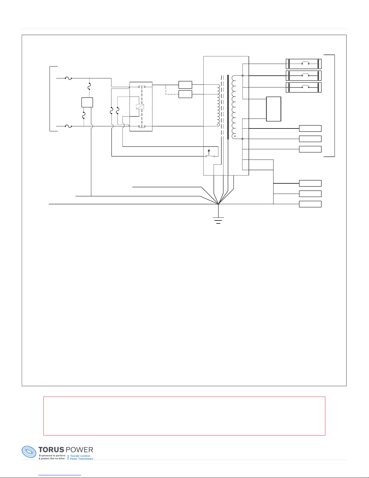
Circuit Schematic - North American WM Model (WM 45 BAL TVSS)
RETAINER BAND
INPUT
GND
L1
240VAC INPUT
L2
F3
25A
F6
15A
F4
25A
CABINET
GND
A5
TVSS
F5
15A
F1
2A
F2
2A
DOOR
GND
3/L2
L2
L1
1/L1
K1
4/T2
2/T1
240V
208V
TB7
TB8
T1
T1,3
T1,2
T1,1
T1,4
T1,5
TS1
T1,6
T1,7
T1,8
T1,10.2
T1,10.1
T1,10
T1,10A
T1,9A
T1,9.2
T1,9.1
T1,9
T1,9B
T1,9B.1
A2W1
(J2)
A4
(J1)
CB3
CB2
CB1
SURGE
PCB
E8
E7
E6
20A
20A
20A
TB1
TB2
TB3
TB4
TB5
TB6
3
2
1
N
N
N
OUTPUT: 120VAC X 3 CIRCUITS
GND
GND
GND
COMPONENT PANEL
T1
TS1
PCB1
CB1-CB3
A4
A5
CUSTOMER WIRING CONNECTIONS
INPUT MAINS SUPPLY:
OUTPUT TO LOAD / EQUIPMENT:
: MAIN POWER TRANSFORMER 5.4KVA
: TRANSFORMER TEMPERATURE LIMIT SWITCH 130°C
NORMALLY CLOSED
: SURGE SUPPRESSION CIRCUIT
: 20A ABB S-201U - K20, OUTPUT CIRCUIT BREAKER
: SURGE SUPPRESSOR ACROSS THE OUTPUT
: TVSS LIEBERT AC POWER LOW EXPOSURE SURGE SUPPRESSOR
L1, L2
CB1, N. CB2, N. CB3, N.
F1-F2
F3-F4
F5-F6
K1
TB1-TB3
TB4-TB6
TB1-TB6
: FUSE: 2.0A FA; 250VAC, 20mm X 5mm
: FUSE: 25A TD; 600VAC, TYPE J; use: LPJ-25SP or JDL25
in holder JT60030, AWG 18 to 8, TORQUE to 2.3Nm / 20 lb-in
: FUSE: 15A FA; 250VAC, 31.75mm X 6.35mm
: 2-POLE CONTACTOR, 30A, 600VAC, COIL: 208-240VAC
: OUTPUT NEUTRAL TERMINAL BLOCK
: OUTPUT GROUND TERMINAL BLOCK
: AWG 16 to 6, TORQUE: 2.0Nm/18 lb-in
Note:
Circuit schematic drawing is provided for reference only, Torus Power
WM units have no user serviceable parts inside. Please return unit to
manufacturer for repair and service when required.
Page 4
Page 7
www.TorusPower.com
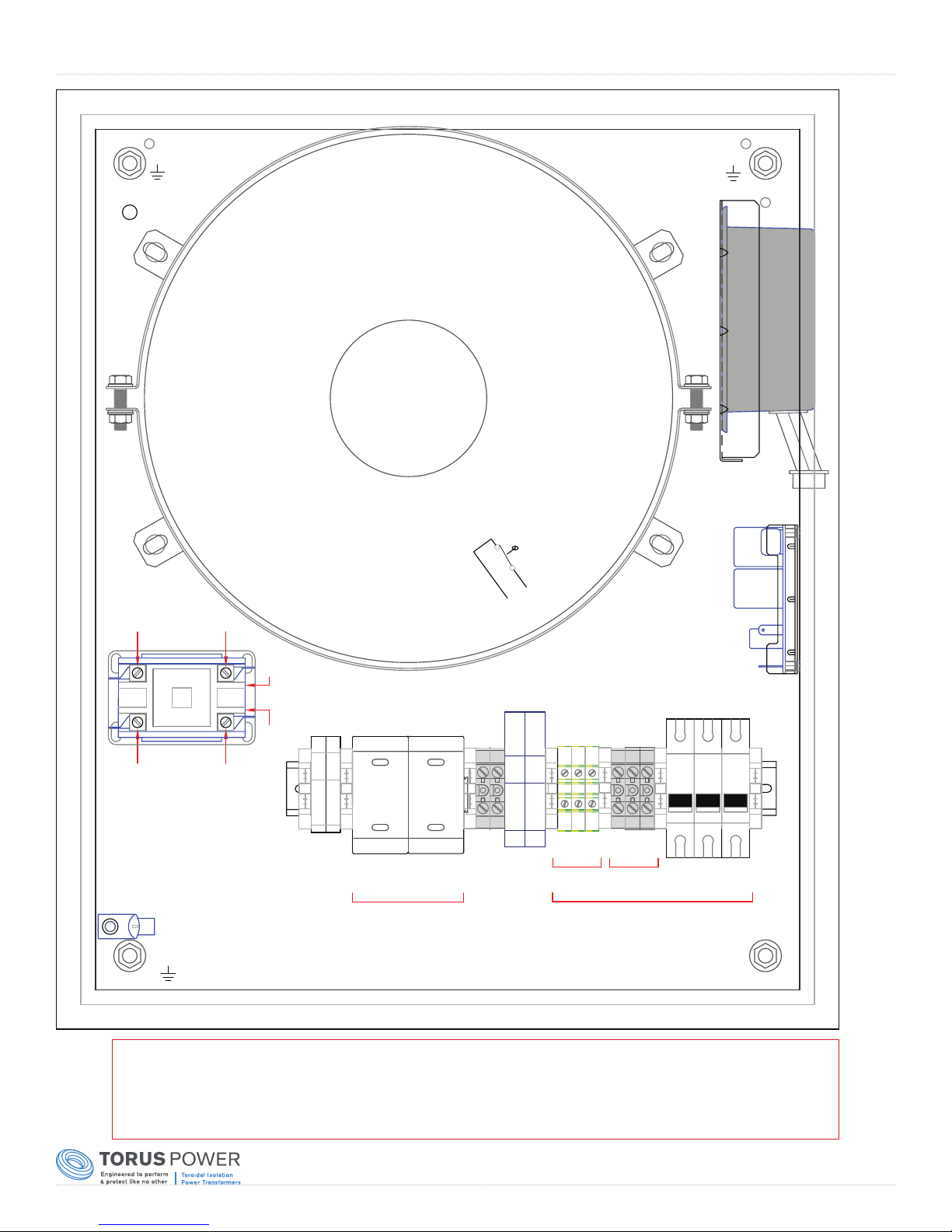
Layout - North American WM Model (WM 45 BAL TVSS)
T1
5.4kVA, 60Hz ISOLATION TRANSFORMER
NOMINAL INPUT = 240VAC
NOMINAL OUTPUT = 120VAC X 3 CIRCUITS
A5
TVSS
2/T1
K1
4/T2
INCOMING GROUND
1/L1
3/L2
T1-10A
T1-10.2
L1
L2
T1-10.1
T1-10
F1-2
F2-2
FF
12
2.0A
2.0A
F1-1
F2-1
TS1
THERMAL
SWITCH N.C.
T1-9B1
T1-9B
T1-9.2
T1-9.1
F3-2
F4-2
L
L
L
L
F3 F4
25A 25A
T
T
L1 L2
F3-1
T
T
F4-1
INPUT
240VAC
T1-9
T1-8
240V
INPUT
SELECT
T1-7
TB7-2
TB8-2
208V
T1-6
F5-2
F6F5
15A
F5-1
T1-5
F6-2
15A
F6-1
T1-1
T1-2
T1-3
T1-4
TB6-2TB6-1
TB5-2
TB5-1
TB1-2
TB1-1
TB4-2
TB4-1
GND
OUTPUT
120VAC
TB2-2
TB2-1
TB3-2TB3-1
PCB1
CB2-2
CB1-2
CB1CB3CB2
20A 20A 20A
2
1N
CB1-1
3
CB2-1
J1
J2
CB3-2
CB3-1
Note:
Layout drawing is provided for reference only, Torus Power WM units have
no user serviceable parts inside. Please return unit to manufacturer for
repair and service when required.
Page 5
Page 8
www.TorusPower.com
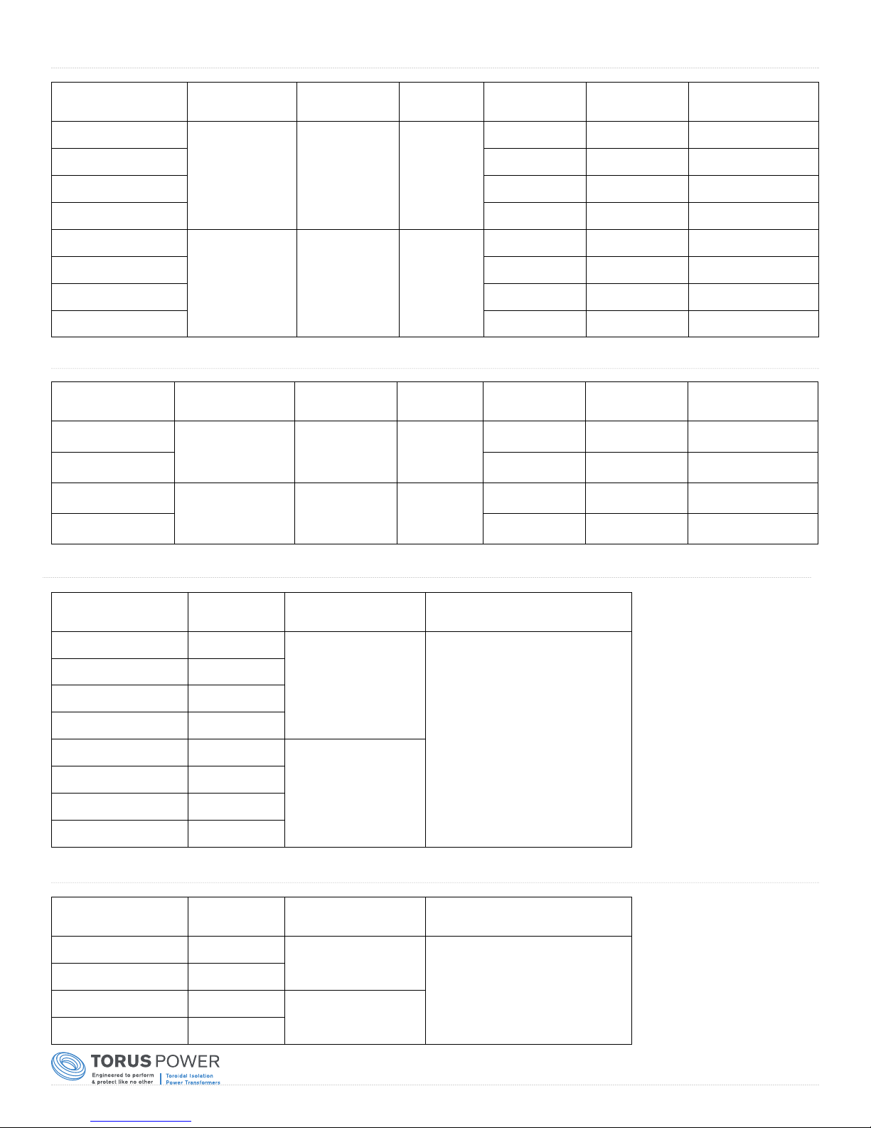
Electrical Specifications - North American Model
Model Number
WM 45 BAL
WM 60 BAL 2x30A (Fuses) 3x20A 60A
WM 75 BAL 2x40A (Fuses) 5x20A 75A
WM 100 BAL 2x50A (Fuses) 5x20A
WM 45 BAL TVSS
WM 60 BAL TVSS 2x30A (Fuses) 3x20A 60A
WM 75 BAL TVSS 2x40A (Fuses) 5x20A 75A
WM 100 BAL TVSS 2x50A (Fuses) 5x20A
Input Voltage
Nominal
240VAC, 60Hz
or
208VAC, 60HZ
240VAC, 60Hz
or
208VAC, 60HZ
Output Voltage
Nominal
120VAC NO
120VAC YES
Surge
Suppression
Input Current
Liming
2x25A (Fuses) 3x20A 45A
2x25A (Fuses) 3x20A 45A
Output Circuit
Breakers
Maximum Available
Output Current
100A
100A
Electrical Specifications - International Model
Model Number
WM 30
WM 45 2x45A (Fuses) 5x15A 45A
WM 30 TVSS
WM 45 TVSS 2x45A (Fuses) 5x15A 45A
Input Voltage
Nominal
220-240VAC,
50/60Hz
220-240VAC,
50/60Hz
Output Voltage
Nominal
220-240VAC NO
220-240VAC YES
Suppression
Surge
Input Current
Liming
2x30A (Fuses) 3x15A 30A
2x30A (Fuses) 3x15A 30A
Output Circuit
Breakers
Maximum Available
Output Current
Mechanical Specifications - North American Model
Model Number
WM 45 BAL 74.5 (164)
WM 60 BAL 86.5 (191)
WM 75 BAL 99.5 (219)
WM 90 BAL 105.5 (233)
WM 45 BAL TVSS 76 (168)
WM 60 BAL TVSS 88 (194)
WM 75 BAL TVSS 101 (223)
WM 90 BAL TVSS 107 (236)
Weight
KG(lb)
Size, mm (HxWxD)
Size, inch (HxWxD)
673x526x261
26.5x20.7x10.3
673x526x261
26.5x20.7x10.3
Construcon
NEMA TYPE 1 Enclosure
14 guage steel
Black Powder Coat
Slip hinges enable door removal
1/4 turn latch
Mechanical Specifications - International Model
Model Number
WM 30 89.5 (197)
WM 45 105.5 (233)
WM 30 TVSS 91 (201)
WM 45 TVSS 107 (236)
Weight
KG(lb)
Size, mm (HxWxD)
Size, inch (HxWxD)
673x526x261
26.5x20.7x10.3
673x526x261
26.5x20.7x10.3
Construcon
NEMA TYPE 1 Enclosure
14 guage steel
Black Powder Coat
Slip hinges enable door removal
1/4 turn latch
Page 6
Page 9
www.TorusPower.com
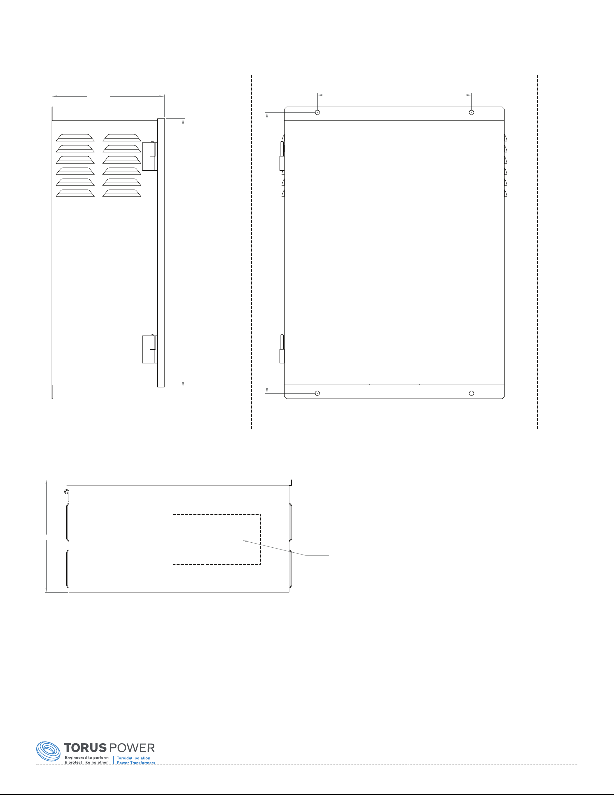
Wall Cabinet External Layout - WM AVR Series
10.250
Space around unit as shown above:
A
10.25"
A
14.00"
25.50"24.37"
A
B
'A' = 5.00"
'B' = 6.00"
"
Customer electrical connections:
Wiring conduit holes should be
added as required to this area.
Page 7
Page 10

www.TorusPower.com
Warranty
Torus Power Inc. products are warranted to be free from manufacturing defects as follows:
• Five years from the original date of sale for toroidal transformers
• Two years from the original date of sale for all other components
The product warranty includes parts, labour and return shipping to the customer. Shipping to Torus Power Inc. for warranty repair
isis the responsibility of the customer.
Warranty coverage is not transferrable and original proof of purchase is required for warranty claims.
In the event of a warranty claim, Torus Power Inc. will remedy the issue by repair or replacement, as we deem necessary, to
restore the product to full performance.
This warranty is considered void if the failure of the product or any component part is caused by damage or misuse.
Failure to fully comply with Torus Power operating instructions voids the warranty.
Page 8
Page 11

Page 12
Rev. 11/02/2016
 Loading...