

Torus Power Consumer, AVR 15 CB, Pro, AVR 20 RK, AVR 20 CB Series Manual
...
AVR Series Manual
™
Isolate.
Protect.
Audio / Video Power Isolation Units
with Automatic Voltage Regulation
19” Pro Series Rack Mount (RK) Faceplate
Inspire!
17” Consumer Series (C) Faceplate
Available in Black (B) and Silver (S) Colours

Table of Contents
Table of Contents
Important Safety Instructions
Shipping Carton & Packing Material
Page 1
Page 2
Page 2
Torus Power AVR Series Power Conditioners User Notes and Manual
Front Panel Display
Rear Panel Connections and AVR Software
AVR Software - Menu Selection
Block Diagram - AVR System
Page 3
Page 4
Page 5
Page 6,7,8
Page 9
Layout Page 9
Schematic North American Model
Schematic International Model
North American Model Numbers
International Model Numbers
Page 10
Page 10
Page 11
Page 11
Typical front Panel Layout of
North American and International Models
Electrical Specifications North American Models
Page 12
Page 12
Mechanical Specifications North American Models
Page 12
Line Cords and Wall Receptacles for
North American Models
Rear Panel Layout of North American Models
Electrical Specifications International Models
Mechanical Specifications International Models
Rear Panel Layout of International Models
Page 13
Page 13
Page 14
Page 14
Page 15
Home Automation Interface Page 16
Warranty Page 16
™
Owner’s Manual AVR Audio / Video Power Isolation Units Rack Mount (RK) / Consumer (C) 04/12Power Conditioners
www.TorusPower.com
REV.04/19/2012
Page 1
Important Safety Instructions
CAUTION!
To reduce the risk of electric shock and fire, do not remove the cover of this device. There
are no user serviceable parts inside. Please refer all servicing to licensed service technicians.
CAUTION!
The international symbol of a lightning bolt inside a triangle is intended to alert the user to
uninsulated “dangerous voltage” within the device’s enclosure. The international symbol of an
exclamation point inside a triangle is intended to alert the user to the presence of important
operating, maintenance and servicing information in the manual accompanying the device.
CAUTION!
CAUTION!
To prevent electrical shock, match wide blade of plug to wide slot, fully insert.
To reduce the risk of electrical shock, do not expose this equipment to rain or moisture.
1. Read Instructions—All safety and operating instructions
should be read before operating the device.
2. Retain Instructions—The safety and operating
instructions should be retained for future reference.
3. Heed Warnings—All warnings on the device and in the
operating instructions should be adhered to.
4. Follow Instructions—All operating and safety instructions
should be followed.
5. Water & Moisture—The device should never be used in,
on or near water for risk of fatal shock.
6. Ventilation—The device should always be located in such
a way that it maintains proper ventilation. It should never
be placed in a built-in installation or anywhere that may
impede the flow of air through its ventilation slots.
7. Heat—Never locate the device near heat sources such as
radiators, floor registers, stoves or other heat-generating
devices.
8. Power Cord Protection—Power cables should be routed
so they are not likely to be stepped on or crushed by items
placed on them or against them. Special attention should
be paid to areas where the plug enters a socket or fused
strip and where the cord exits the device.
9. Periods Of Non-Use—The device should be unplugged
when not being used for extended periods.
10. Dangerous Entry—Care should be taken that no foreign
objects or liquids fall or are spilled inside the device.
11. Damage Requiring Service—The device should be
serviced by licensed technicians when:
• The plug or power supply cord has been damaged.
• Objects have fallen or liquid has spilled inside the device.
• The device has been exposed to moisture.
• The device does not appear to be operating properly or
exhibits a marked change in performance.
• The device has been dropped or the enclosure becomes
damaged.
12. Service—The device should always be serviced by
licensed technicians. Only replacement parts specified by
the manufacturer should be used. The use of unauthorized
substitutions may result in fire, shock, or other hazards.
13. Do not position the equipment so that it is difficult to
operate the disconnecting device (power cord).
14. If the equipment is used in a manner not specified by
the manufacturer, the protection provided by the
equipment may be impaired.
15. The power switch should be in the “off” position when
connecting or disconnecting equipment from a Torus Power
unit.
16. Some units can be very heavy, please use
CAUTION
safe practices when lifting.
Shipping Carton & Packing Material
Please keep the original shipping box and all packing material.
This will ensure the AVR is protected in future transport.
In the unlikely event you have a problem and must return it for
service you must use the original packing material.
Ship the AVR only in the original packing material, as the unit
is not insurable by carriers otherwise.
™
Owner’s Manual AVR Audio / Video Power Isolation Units Rack Mount (RK) / Consumer (C) 04/12Power Conditioners
³18 kg (39.7 lb)
³32 kg (70.5 lb) ³55 kg (121.2 lb)
www.TorusPower.com
REV.04/19/2012
Page 2

Torus Power AVR Series Power Conditioners - User Notes and Manual
Placement and ventilation
Allow 1” distance on all sides when positioning the AVR for proper ventilation, and allow 6” behind the
AVR fo r adequate wiring space. Do not place heat-generating devices directly below t he AVR.
Connecting components and using the AVR
Using the AVR is as simple as plugging in a udio and video components to the outlets on the rear panel.
The order and position in which you connect your components will not affect theperformance of the
AVR or your components. Connect th e AVR to the wall outlet, and switch it on. Turn on the
components individually.
While the AVR has built-in software that can be accessed via the Ethernet connection, there is no need
for you to use this software. The AVR system provides all the standard features, performance, and
benefitsoutoftheboxbysimplypluggingitinasdescribedinthissection. YoucanusetheAVR
software to monitor the voltage conditions via your computer, and for such additional features as being
able to turn your system on/off remotely and change the duration of the displays backlight.
Torus AVR – Description
Torus Power AVR (Automatic Voltage Regulation) is a full- feature state-of-the-art p ower conditioner,
isolating and p rotecting your system. Like all Torus Power products, the AVR series provides true
isolation (using massive toroidal transformers) and protect s all connected equipmentfrom the risk o f
severe pow er line surges using series-mode surge suppr ession. In addition, Torus AVR provides stable
voltage to kee p equipment running in the optimal range of 115VAC to 125VAC for any input voltage
from 90V to 130VAC. (International units operate within nominal input voltage such as 220V, 230V,
240V; Torus AVR keeps them operating within a ran ge of +/- 10V. ) See table on Pa ge 9 for more
deta ils.
Torus Power AVR series uses a micro-processor to monitor and control th e power provided to
connected components. The front panel display on the Torus Power AVR indicates input and output
voltages, and displays output current, as well as displaying fault condition s.
The Torus Power AVR is pre-programmed to power down the system when a high or low fault
conditions occurs (user can over-ride).
There are multiple interfaces built into the Torus Power AVR:
1) Et hernet interface with built-i n web ser ver allows any computer to view voltage and current
readingsandturntheAVRunitonoroff.
2) RS-232 is provided for connection to media control systems.
3) Two 12V t riggers are provi de d.
Does your system n eed automatic voltage regulation?
Under ideal conditions, when the supplied power line is stable and dependable, you may not need
voltage regulation. In such an ideal situation, your equipment can operate wit hin t he normal t olerance
ofthelinevoltage.
In reality, the power supplied to most areas is less than ideal due to 0 utdated power grids. In most
areas, the power regularly drops or rises above the accep table range (in North America +/– 5V,
Europe/Asia/ Australia +/- 10V) . These voltage sags, brownouts, and surges can stress components
and shorten equipment life. In the worst case, catastroph ic events can destroy valuable equipment . In
such real-world conditions, Torus Power AVR can protect your equipment, and improve the quality and
enjoyment of your audio a nd video experience.
™
Owner’s Manual AVR Audio / Video Power Isolation Units Rack Mount (RK) / Consumer (C) 04/12Power Conditioners
www.TorusPower.com
REV.04/19/2012
Page 3
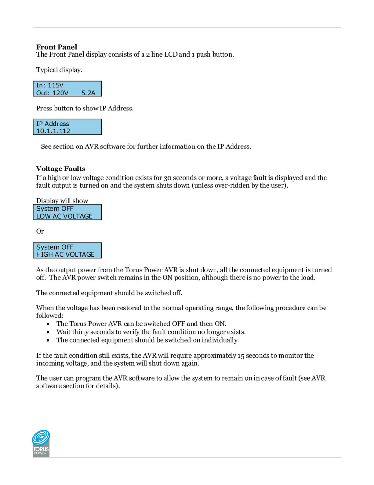
Front Panel Display
(If ethernet connection is used)
™
Owner’s Manual AVR Audio / Video Power Isolation Units Rack Mount (RK) / Consumer (C) 04/12Power Conditioners
www.TorusPower.com
REV.04/19/2012
Page 4
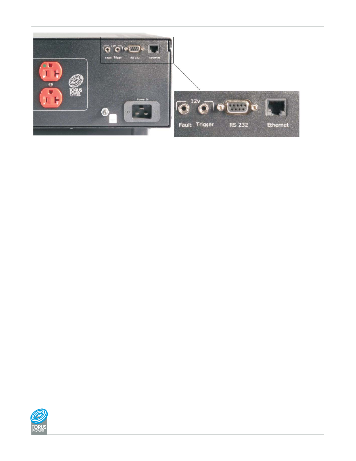
Rear Panel Connections and AVR Software
Figure 1: AVR Rear Panel connections.
Ethernet
Allows access to the AVR and internal software. See AVR Software section for moredetails.
RS232
Allows access to automation and external control. See Home Automation Interface commands at end
of manual.
12V Trigger On/Off
TheAVRcanbeturnedonandoffbya12volttriggerinput. Applying12voltsturns ontheAVRand
removing the 12 volts turns it off.
12V Fault Output
The AVR provides a 12 volt fault output through a jack on the back panel. The output goes to 12 volts
when a relay or voltage fault is detected. The maximum current that can be drawn from this output is
75 mA.
AVR Software
AVR software is resident in the microprocessor on the internal control b oard. There are two m ethods
to access the software.
1) Connect the AVR to the Ethernet p ort. Open a browser window on a PC that is connected to the
same network through another Ethernet port. Enter AVR (or th e I.P address displayed on the LCD)
into the browser window. Press ENTER and the software will open.
2) Use a three way Hub, which is connected to an existing network. You then connect both PC and
AVR to the same Hub. Open a browser wind ow from the PC. Type AVR, (or the I.P address displayed
on the LCD) into the browser window. Press ENTER and the software will ope n.
Username and Password
ThepasswordisrequiredtochangethesetupoftheTorusunit.
Username is admin This is fact ory set and cannot be change d
Password is avr This is the default password, and can be changed.
In case you forget your password, the AVR can be res tored to the factory default password avr
by pressing and holding the button on the front panel for at least 10 seconds.
™
Owner’s Manual AVR Audio / Video Power Isolation Units Rack Mount (RK) / Consumer (C) 04/12Power Conditioners
www.TorusPower.com
REV.04/19/2012
Page 5
 Loading...