

Torque Fitness TQ5-001 Assembly And Maintenance Manual

Version: TQ5-001 Part #: 5158001-A
Assembly and Maintenance Guide
Hybrid
TM
Strength Technology Gym System

Important Safety Instructions …………………………………………………..3
Important Safety Instructions for Using the Equipment ……………......3
Important Safety Instructions for Assembling the Equipment …………3
Obtaining Service……………………………………………….................3
General Notes………………………………………………………………………4
Unpacking the Equipment………………………………………………….4
Tools Required………………………………………………………………4
Optional Equipment…………………………………………………………4
Assembly Tips……………………………………………………………….4
Parts List…………………………………………………………………………….5
Assembly Instructions……………………………………………………………6-39
Adjustments and Maintenance………………………………………………….34-39
Cable Adjustments………………………………………………………….34
Attachment Instructions…………………………............................….... 38
Maintenance………………………………………………………………...39
Assembly Checklist……………………………………………………………….41
Warranty Statement……………………………………………………………….43-44
Warranty Registration…………………………………………………………….45-46
TABLE OF CONTENTS
Page 2

Page 3
Name:____________________________________
Address:__________________________________
Tele:_________ Contact Person:_______________
There is a risk assumed by individuals who use this type of equipment. To minimize risk, you must follow these precautions:
1. READ ALL INSTRUCTIONS AND WARNING LABELS COMPLETELY PRIOR TO ANY USE OR ASSEMBLY. Failure to read and follow the safety instructions and
warnings within the Assembly and Maintenance Guide may result in possible serious injury or death. Use this product only for the intended uses described in the
Assembly and Maintenance Guide and exercise chart. DO NOT modify equipment in any way. Any use other than as intended or modification of product will void any
and all product warranties.
2. Consult your physician before starting any exercise program. Warm up properly before engaging in resistance training. Stop exercising and consult a physician immediately if
you experience dizziness, nausea, faintness, chest pain, shortness of breath or any other abnormal symptoms during use of this equipment.
3. Certain exercise programs and/or equipment may not be suitable or appropriate for pregnant women, people with heart conditions, balance impairments or other pre-existing
health problems. Persons with disabilities should consult a physician and obtain medical approval prior to using this product and should only use this product under close
supervision. Failure to comply with these instructions will void any and all product warranties.
4. Carefully inspect equipment before each use. Replace all parts at the first sign of wear or damage. Tighten all loose connections. Pay special attention to cable ends and
connections. Do not disassemble, remove any parts or components or otherwise attempt to repair this product. DO NOT use product if product appears damaged. DO NOT
attempt to fix a broken or jammed machine, obtain assistance from your authorized Torque Fitness Dealer. Failure to comply with these instructions will void any and all
product warranties.
5. Keep body and clothing clear of all moving parts. Do not put any foreign objects on or near this product when in use. Wear comfortable clothing which does not impair
freedom of movement. Do not wear clothing which is too loose and could get caught in moving parts.
6. Make sure all adjustment spring pins are fully engaged after making an adjustment and before using the product.
7. Make sure weight stack selector is completely inserted into the weight stack before beginning any exercise.
8. Children and pets must not be allowed near this machine. Supervise teenagers. This product is not a toy.
9. If unsure of the proper use of this product, contact your authorized Torque Fitness dealer or Torque Fitness Customer Service at 1-877-TORQUE5 (1-877-867-7835) or
outside the U.S. +1-763-754-7533.
Important Safety Instructions for Assembling Equipment
1. It is strongly recommended that a qualified, authorized Torque Fitness dealer assemble the equipment. Assistance is required. Torque Fitness recommends
using more than one person to assemble this equipment.
2. This product must be assembled on a flat, level surface to assure its proper function. Locate the unit a few inches from walls or furniture to allow easy access during
assembly and use.
3. Read each numbered step in the Assembly and Maintenance Guide and follow the steps in sequence. Skipping ahead may result in damage to the equipment and may
require components to be disassembled.
4. Wear proper attire during the assembly process. Do not wear clothing which is too loose or open toed shoes.
Important Safety Instructions for Using the Equipment
Model number: _________________________________
Serial number(s): _______________________________
Dealer information:______________________________
Date of purchase:______________________
Dealer Service Contract:_________________
Dealer Service Phone:___________________
Refer to the Adjustments and Maintenance section at the back of this manual and the included Exercise Chart for information on product operation and service.
For further information, contact an authorized Torque Fitness dealer or visit our web site at
www.torquefitness.com
If you call or email Customer Service, have the model number and serial number(s) available. The locations of the model and serial numbers are indicated in the back of this
manual. For future reference, write the model and serial number(s) in the space provided below.
Obtaining Service
Do not attempt to service the equipment yourself except for the maintenance tasks described in this manual.

Page 4
GENERAL NOTES
CAUTION: More than one person is required to
assemble this unit. Do not attempt to assemble
by yourself.
Torque Fitness strongly recommends having a
qualified, authorized Torque Fitness Dealer
assemble the equipment.
Unpacking the Equipment
This product is packaged and shipped in multiple
boxes. Parts from all of the boxes are required for
various steps during the assembly process.
Carefully open each box and arrange all parts near
area where assembly is to take place.
CAUTION: Use extreme care when cutting plastic tie
wraps and package banding. A wire cutter works best
for protecting yourself and the parts.
CAUTION: Some of the internal boxes may contain
upholstery. Do not use a utility knife to open any
boxes or the pads may be damaged.
The hardware is packed in separate bags sorted by
step. Carefully open each bag and keep sorted.
Before starting assembly, identify each part and
hardware item as listed in the parts list. If any items
are missing, contact the dealer whom you purchased
the unit from or call Torque Fitness Customer Service.
Note: Some items listed in the parts list may already
be pre-installed on the parts.
§ Read all caution notes on each page before
beginning that step.
§ Some of the items shown in the assembly
steps may already be pre-installed.
§ Note: Some pre-installed parts may need to
be temporarily disassembled in order to
complete a step. Follow the instructions or
damage to the unit could occur.
§ Some parts may have extra holes that you
will not use. Use only the holes depicted in
the instructions.
§ Certain parts make reference to the right and
left side of the machine. In order to remain
consistent, determine the left and right side
of the machine as if you are by sitting with
your back to the rear of the machine.
§ Provide ample space around the machine in
order to ease assembly.
§ DO NOT fully tighten any connections until
instructed to do so. This will help ensure
that alignment of all of the parts will be
correct.
§ Insert all bolts in the direction indicated by
the illustrations. Failure to do so may result
in clearance issues and will degrade the
aesthetics of your unit.
§ Carefully follow instructions for all pivot
points. In general, primary rotating parts
have connections that should be securely
tightened, while secondary connections
need to be loosened ¼ turn.
Tools Required
§ Rubber mallet or hammer
§ ¾” wrench or adjustable wrench
§ Ratchet with 9/16” socket
§ 9/16” box wrench
§ 4mm Allen wrench
§ 5mm Allen wrench
§ 6mm Allen wrench
§ 8mm Allen wrench
§ 7/16” wrench or socket
§ Wire tie cutter (cuts plastic tie wraps)
§ Scissors or utility knife (cuts hardware bags)
§ Step stool
§ Measuring tape
Optional Equipment
Optional equipment may be available for this
product.
Follow the instructions in the optional equipment
instructions for the sequence step to assemble it to
the base unit.
Assembly Tips
§ In a continual effort to improve our products,
specifications are subject to change.
§ A 6-inch scale is provided at the bottom of
every assembly instruction page. The head
of the bolt should not be used when measuring the length of the bolt as depicted in the
illustration below.
1 2 3 6
1 2 3 4 5 6

Page 5
Parts List
QTY
1
1
34
10
6
1
1
6
2
2
6
2
2
1
9
1
1
1
2
1
2
4
2
1
1
1
2
2
2
1
2
1
2
1
2
1
DESCRIPTION
REAR BASE
BASE
3/8” FLAT WASHER
3/8 X 3/4” BUTTON HEAD BOLT W/NP
3/8 X 2-1/4” BUTTON HEAD BOLT W/NP
REAR UPRIGHT
FRONT UPRIGHT
3/8 X 2-3/4” BUTTON HEAD BOLT
3/8 X 3” BUTTON HEAD BOLT
3/8 X 2” BUTTON HEAD BOLT
3/8 “ CURVED WASHER
1/2” FLAT WASHER
3/8 X 1-1/4” BUTTON HEAD BOLT
3/8 X 4” BUTTON HEAD BOLT
3/8” LOCKNUT
MID PULLEY ARM PIVOT
TOP BOOM
PRESS ARM
1/2 X 1” BUTTON HEAD BOLT W/NP
SEAT PAD
PIVOT ARM
19mm PIVOT BUSHING
MID SWIVEL PULLEY
BACK PAD
LE/LC ARM
LC KNEE HOLD DOWN
FLANGE SPACER
3/8” ORANGE PIVOT WASHER
GUIDE ROD
STACK/SHROUD SUPPORT
WEIGHT STACK CUSHION
FLOATING TIBIA
19mm SHAFT COLLAR
4-1/2” DUAL FLOATING PULLEY
4-1/2” FLOATING PULLEY
3-1/2” SINGLE FLOATING PULLEY
#
1
2
3
4
5
6
7
8
9
10
11
12
13
14
15
16
17
18
19
20
21
22
23
24
25
26
27
28
29
30
31
32
33
34
35
36
PART NO.
5139601
51237PA
2001101
2004001
2004007
50612PA
50607PA
2001009
2001010
2001006
2003001
2001301
2001003
2001014
2001201
51248PA
5145901
50686PA
2003302
5110601
51425PA
5146601
5146201
5051701
5146301
50996PA
5099501
5101001
5157801
51447PA
5098201
51449PA
5095301
51420PA
51422PA
50717PA
QTY
1
1
2
2
22
2
14
6
4
1
1
1
1
1
2
1
1
1
2
2
3
2
1
19
1
1
1
1
1
2
1
1
1
2
2
1
DESCRIPTION
BOTTOM RIGHT SHROUD
BOTTOM LEFT SHROUD
3/4” SPACER
1/4” LOCK NUT
1/4” FLAT WASHER
1/4” X 3/4” BUTTON HEAD BOLT
1/4” X 1/2” BUTTON HEAD BOLT
3/8 X 1/2” BUTTON HEAD BOLT W/NP
1/4” X 1/4” BUTTON HEAD BOLT
TOP LEFT SHROUD
TOP RIGHT SHROUD
TQ5 WALL CHART
BLACK TOUCH-UP PAINT
SILVER TOUCH-UP PAINT
GUIDE ROD LUBE PACKET
SHORT STRAP HANDLE
DUAL PULLEY LAT BAR
ANKLE STRAP
UNIVERSAL ADPATER
SNAP HOOK
MEDIUM STRAP HANDLE
CABLE END SLEEVE
3-1/2” PULLEY
WEIGHT PLATE
WEIGHT STACK HEAD PLATE
WEIGHT STACK SELECTOR FORK
WEIGHT STACK LABEL
WEIGHT STACK CABLE
LEG CURL/EXT CABLE
FLOATING PULLEY CABLE
HIGH/MID PULLEY CABLE
PRESS ARM PIVOT
PRESS ARM ADJ PLATE
3/8 X 1-3/4” BUTTON HD BOLT W/NP
3/8 X 3/4” FLAT HEAD BOLT
3/8 X 1-3/4” BUTTON HEAD BOLT
#
37
38
39
40
41
42
43
44
45
46
47
48
49
50
51
52
53
54
55
56
57
58
59
60
61
62
63
64
65
66
67
68
69
70
71
72
PART NO.
5145301
51454PA
5199401
2002001
2002101
2001902
2001901
2004026
2001912
5145601
5145501
5157901
5110101
5110001
5101501
5044101
5091201
5091701
5091901
5091801
5114501
5097301
5094401
5050901
5050401
5051201
5093101
5160101
5160901
5160201
5160301
51244PA
51451PA
2004005
2004102
2001005
Page 6
1 2 3 4 5 6
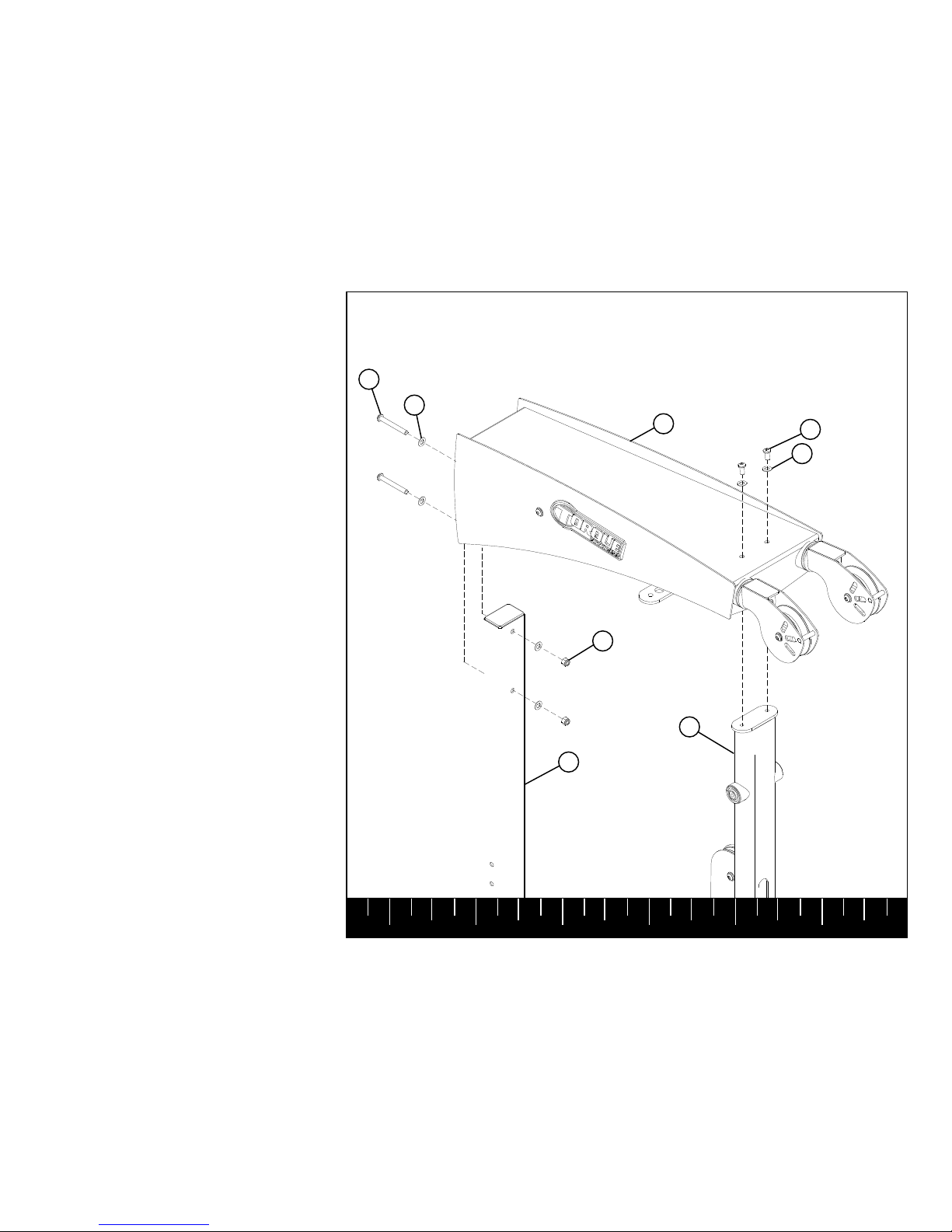
STEP 1
Assemble the BASE (2) to the REAR BASE (1)
using:
Two 3/8 X 3/4” BOLTS W/NP (4)
Two 3/8” FLAT WASHERS (3)
NOTE: Do
NOT fully tighten any connec-
tions until instructed to do so SECURELY.
NOTE: Do NOT fully tighten.
1
3
3/8 X 3/4” 4
W/NP
2
Assemble the REAR UPRIGHT (6) to the
REAR BASE (1) using:
Two 3/8 X 3/4” BOLTS (4) W/NP
Two 3/8” FLAT WASHERS (3)
NOTE: Do NOT fully tighten any connections until instructed to do so SECURELY.
Page 7
1 2 3 4 5 6
STEP 2
6
3
3/8 X 3/4” 4
W/NP
2
1
Assemble the FRONT UPRIGHT (7) to the
BASE (2) using:
Two 3/8 X 2-3/4” BOLT (8)
Four 3/8” FLAT WASHERS (3)
Two 3/8” LOCK NUTS (15)
NOTE: Do NOT fully tighten any connections until instructed to do so SECURELY.
Page 8
1 2 3 4 5 6
STEP 3
3
2
7
8 3/8 X 2-3/4”
15
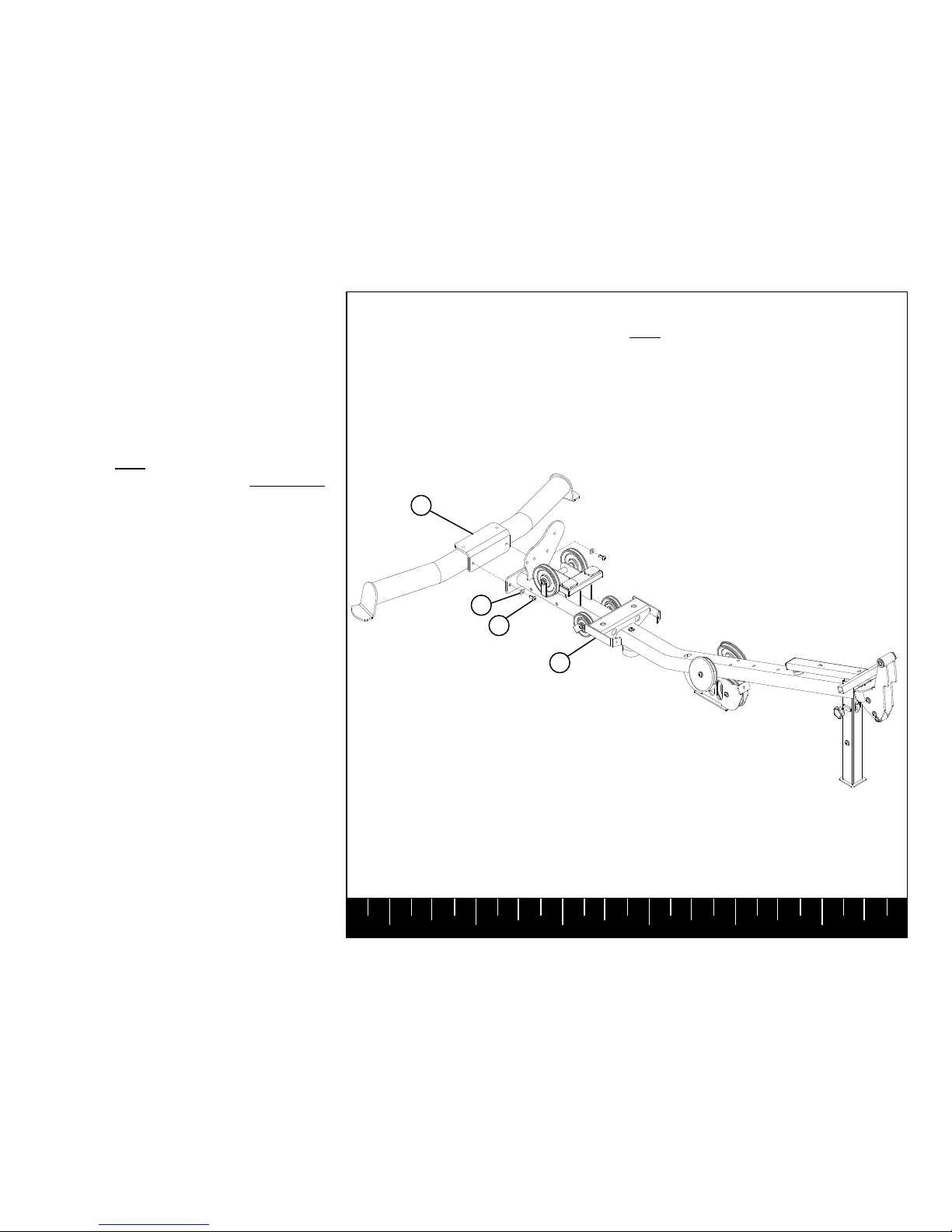
Assemble the MID PULLEY ARM PIVOT (16)
to the FRONT UPRIGHT (7) & BASE (2) using:
Four 3/8 X 2-3/4” BOLTS (8)
Eight 3/8” FLAT WASHERS (3)
Four 3/8” LOCK NUTS (15)
NOTE: Do NOT fully tighten any connections until instructed to do so SECURELY.
Page 9
1 2 3 4 5 6
STEP 4
15
2
3
15
16
3/8 X 2-3/4” 4
7
8 3/8 X 2-3/4”
Page 10
1 2 3 4 5 6
STEP 5
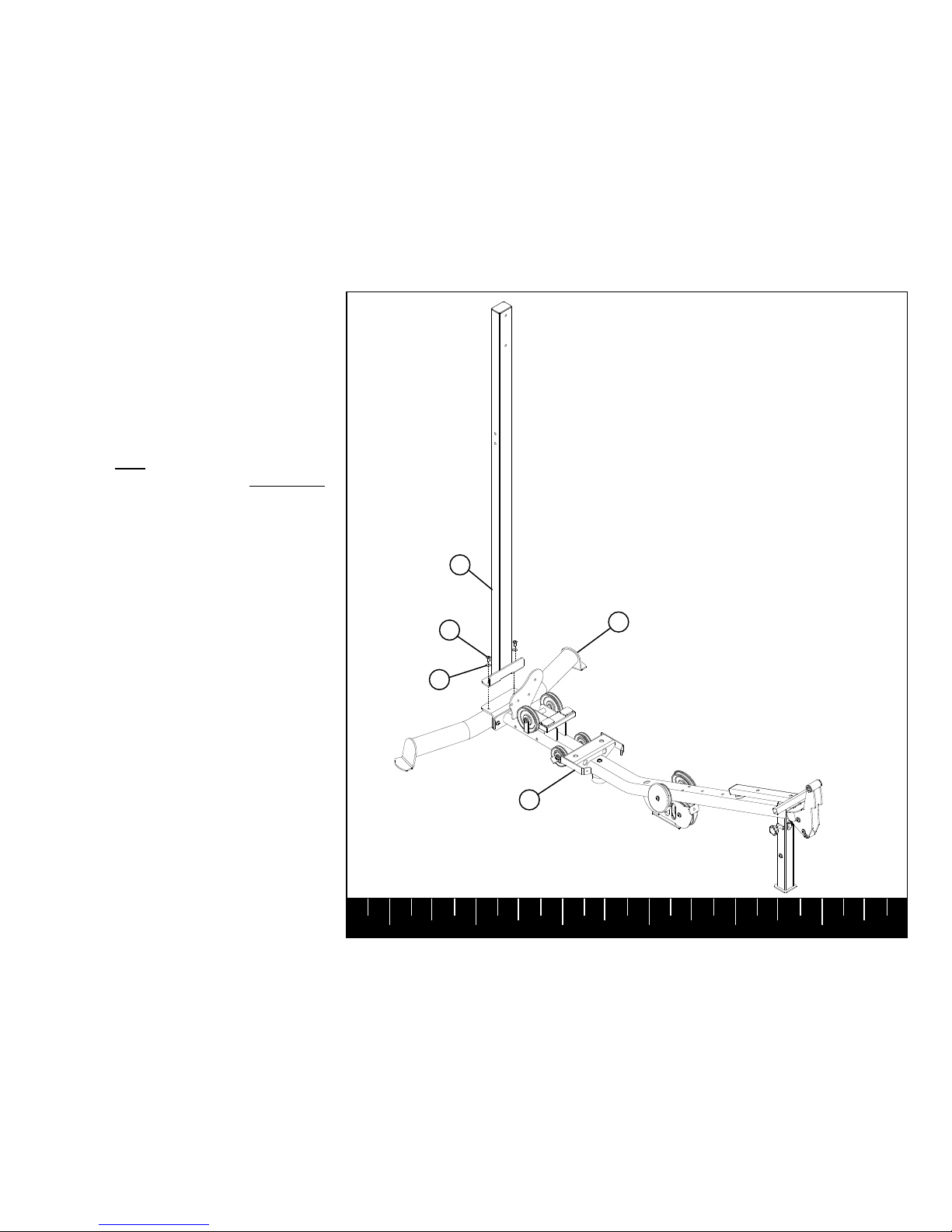
Assemble the TOP BOOM (17) to the FRONT
UPRIGHT (7) using:
Two 3/8 X 3/4” BOLTS W/NP (4)
Two 3/8” FLAT WASHERS (3)
Assemble the TOP BOOM (17) to the REAR
UPRIGHT (6) using:
Two 3/8 X 3” BOLTS (9)
Four 3/8” FLAT WASHERS (3)
Two 3/8” LOCK NUTS (15)
17
9 3/8 X 3”
4 3/8 X 3/4”
W/NP
15
3
3
6
7
Page 11
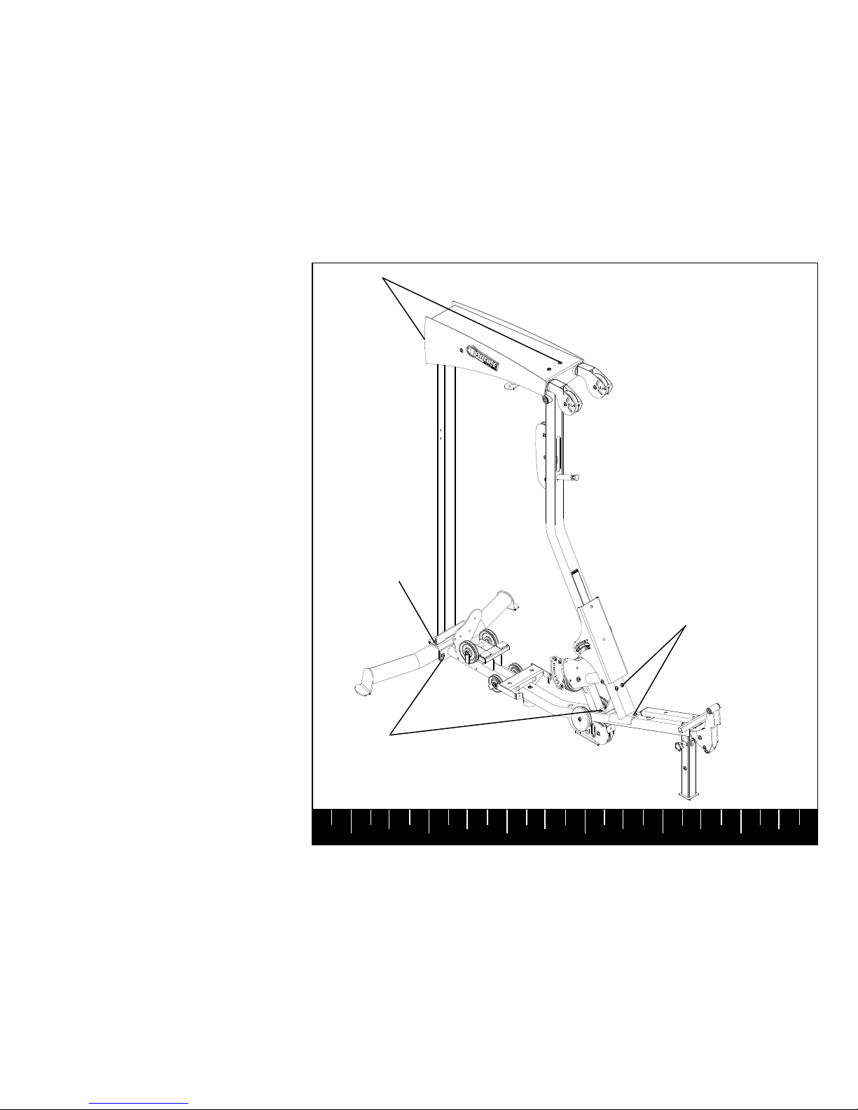
1 2 3 4 5 6
STEP 6
SECURELY tighten ALL the previous frame
connections.
.
SECURELY
TIGHTEN!
SECURELY
TIGHTEN!
SECURELY
TIGHTEN!
SECURELY
TIGHTEN!
Page 12
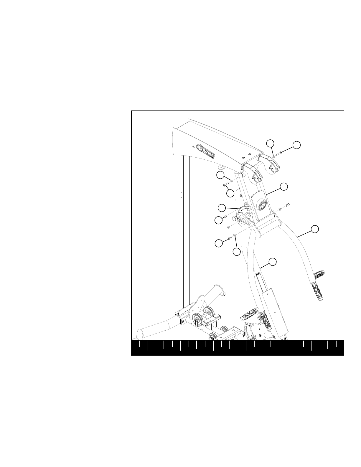
1 2 3 4 5 6
STEP 7
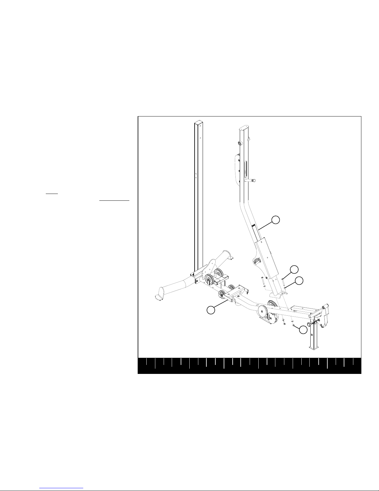
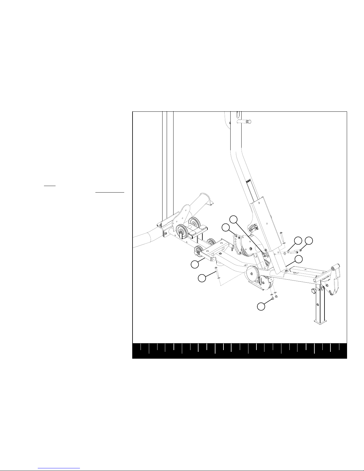
SECURELY assemble the PRESS ARM PIVOT
(68) to the FRONT UPRIGHT (7) using:
Two 3/8 X 2-1/4” BOLTS W/NP (5)
Two 3/8” FLAT WASHERS (3)
SECURELY assemble the PRESS ARM ADJ
PLATE (69) to the PRESS ARM PIVOT (68)
using:
Two 3/8 X 3/4” FLAT HEAD BOLTS (71)
SECURELY assemble the PRESS ARM (18) to
the PRESS ARM PIVOT (68) using:
Two 1/2” X 1” BOLTS W/NP (19)
Two 1/2 FLAT WASHERS (12)
7
5 3/8 X 2-1/4”
W/NP
18
3/8 X 2-1/4” 5
W/NP
3
68
12
3
3/8 X 3/4” 71
FLAT HEAD
69
1/2 X 1” 19
W/NP
Page 13
1 2 3 4 5 6
STEP 8
Pull back SPRING PIN on the BASE (2) and
slide the SEAT SUPPORT up to the top position. Make sure SPRING PIN engages the hole
on the SEAT SUPPORT fully.
SECURELY assemble the SEAT PAD (20) to
the SEAT SUPPORT using:
Two 3/8 X 2” BOLTS (10)
Two 3/8” FLAT WASHERS (3)
2
20
SPRING
PIN
3
3/8 X 2” 10
SEAT SUPPORT
Page 14
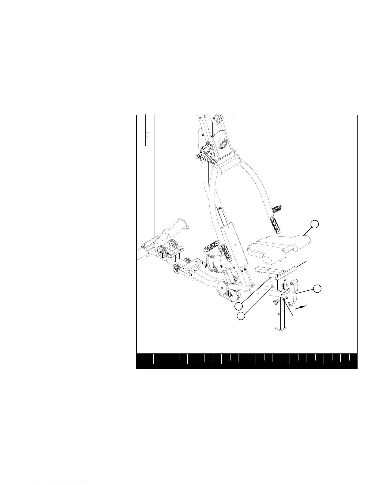
1 2 3 4 5 6
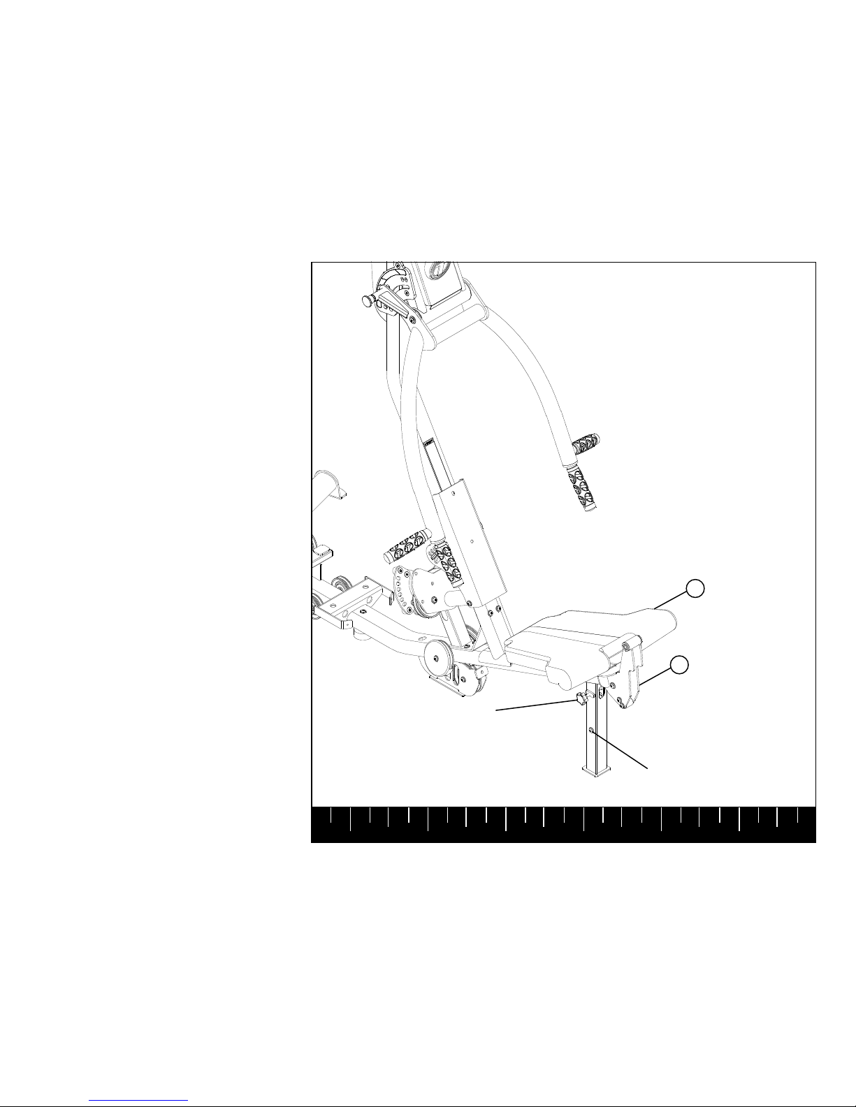
STEP 9
To secure the SEAT PAD (20) to the BASE (2),
tighten the KNOB on the vertical tube on the
BASE (2).
To adjust the SEAT PAD (20), loosen the
KNOB on the BASE (2); pull out the POP PIN
and pull up on the SEAT PAD (20). If the SEAT
does not adjust smoothly, slightly loosen the
retaining bolt in the vertical tube on the BASE
(2).
KNOB
2
RETAINING BOLT
20
 Loading...