

Torque Fitness MJ-SP Assembly Instructions Manual
MJ-SP SHOULDER PRESS
MJ-SP SHOULDER PRESS
MJ-SP CABLE TECHNOLOGY SHOULDER PRESS

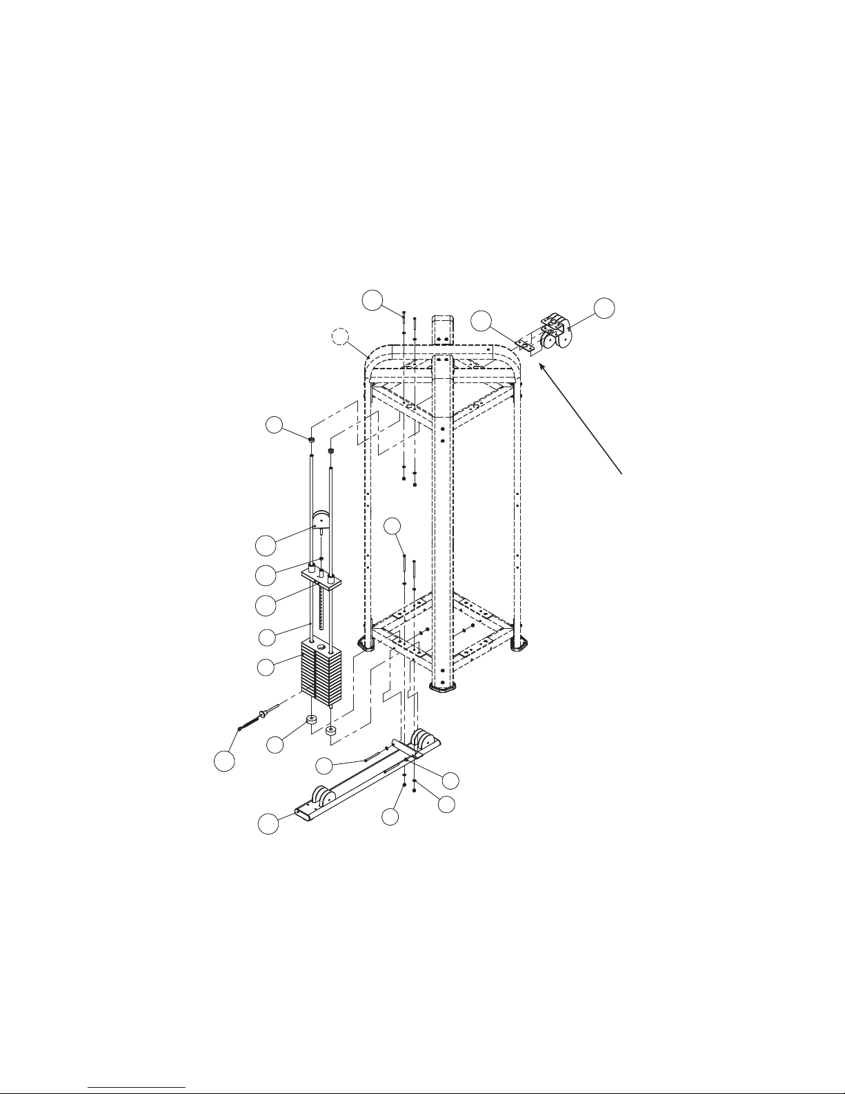
PARTS LIST - STEP 1
ITEM PART NUMBER DESCRIPTION QTY
1 MJ-T Tower Assembly 1
2 P01-5184 Guide Rod 2
3 A05-0212 Alum. Collar w/ Set Screw 2
4 DABE03843416NU Cap Head Screw 3/8” x 4 3/4”” L 4
5 DC322010015U 3/8” Curved Washer 4
6 DC120010510U 3/8” Flat Washer 8
7 DB2E03811000U Lock Nut 3/8” x 11t 6
8 P06-0034 Weight Stack Cushion 2
9 P10-0862 WEIGHT PLATE, 10 lb 15
10 P20-5014 Top Plate w/ Selector Stem Assy 1
11 P05-0036 Nut 1/2” x 7.8t 1
12 P11-0210 Selector Pin 1
13 P04-4404 Top Pulley Bracket 1
14 P02-6927 Spacer Plate (used when without Shroud) 1
15 DABE03831416NU Cap Head Screw 3/8” x 3 1/4” L 2
16 P04-3849 Single Pulley Bracket 1
17 P20-5017 Bottom Tube Assy 1
Position Bottom Tube Assembly (17) in place prior to installing weight stack.
After weight stack is assembled, raise guide rods and hold in elevated position with bolts used in Bottom Tube Assembly.
Raise Collars (3) to the top of the guide rods and secure in place using Allen wrench.
Clean surface of weight stack and install weight stack labels.
4
1
6
14
15
3
16
11
10
9
12
8
2
4
17
5
13
7
ASSEMBLY - STEP 1
Note: If optional shrouds are
to be assembled, replace item
14 with upper shroud bracket
found in shroud box.
 Loading...