

Torque Fitness F5 Assembly And Maintenance Manual

Part #: 5099201-CVersion: F5-01-001
Assembly and Maintenance Guide
Fold Away Strength Trainer
TM

Page 2
Important Safety Instructions …………………………………………………..3
Important Safety Instructions for Using the Equipment ………………...3
Important Safety Instructions for Assembling the Equipment ………….3
Obtaining Service ................................................................………….3
General Notes………………………………………………………………………4
Unpacking the Equipment………………………………………………….4
Tools Required………………………………………………………………4
Optional Equipment…………………………………………………………4
Assembly Tips……………………………………………………………….4
Parts List…………………………………………………………………………….5-6
Assembly Instructions……………………………………………………………6-44
Adjustments and Maintenance………………………………………………….41,44
Cable Adjustments………………………………………………………….41
Attachment and Adjustment Instructions…………………………………44
Maintenance…………………………………………………………………44
Assembly Checklist……………………………………………………………….46
Warranty Statement……………………………………………………………….47-48
Warranty Registration…………………………………………………………….49-50
TABLE OF CONTENTS

Page 3
Name:____________________________________
Address:__________________________________
Tele:_________ Contact Person:_______________
There is a risk assumed by individuals who use this type of equipment. To minimize risk, you must follow these precautions:
1. READ ALL INSTRUCTIONS AND WARNING LABELS COMPLETELY PRIOR TO ANY USE OR ASSEMBLY. Failure to read and follow the safety instructions and warnings
within the Assembly and Maintenance Guide may result in possible serious injury or death. Use this product only for the intended uses described in the Assembly and
Maintenance Guide and exercise chart. DO NOT modify equipment in any way. Any use other than as intended or modification of product will void any and all product
warranties.
2. Consult your physician before starting any exercise program. Warm up properly before engaging in resistance training. Stop exercising and consult a physician immediately if you experience dizziness, nausea, faintness, chest pain, shortness of breath or any other abnormal symptoms during use of this equipment.
3. Certain exercise programs and/or equipment may not be suitable or appropriate for pregnant women, people with heart conditions, balance impairments or other preexisting health problems. Persons with disabilities should consult a physician and obtain medical approval prior to using this product and should only use this product
under close supervision. Failure to comply with these instructions will void any and all product warranties.
4. Carefully inspect equipment before each use. Replace all parts at the first sign of wear or damage. Tighten all loose connections. Pay special attention to cable ends and
connections. Do not disassemble, remove any parts or components or otherwise attempt to repair this product. DO NOT use product if product appears damaged. DO
NOT attempt to fix a broken or jammed machine, obtain assistance from your authorized Torque Fitness Dealer. Failure to comply with these instructions will void any and
all product warranties.
5. Keep body and clothing clear of all moving parts. Do not put any foreign objects on or near this product when in use. Wear comfortable clothing which does not impair
freedom of movement. Do not wear clothing which is too loose and could get caught in moving parts.
6. Make sure all adjustment spring pins are fully engaged after making an adjustment and before using the product.
7. Make sure weight stack selector is completely inserted into the weight stack before beginning any exercise.
8. Children and pets must not be allowed near this machine. Supervise teenagers. This product is not a toy.
9. If unsure of the proper use of this product, contact your authorized Torque Fitness dealer or Torque Fitness Customer Service at 1-877-TORQUE5 (1-877-867-7835) or
outside the U.S. +1-763-754-7533.
Important Safety Instructions for Assembling Equipment
1. It is strongly recommended that a qualified, authorized Torque Fitness dealer assemble the equipment. Assistance is required. Torque Fitness recommends
using more than one person to assemble this equipment.
2. This product must be assembled on a flat, level surface to assure its proper function. Locate the unit a few inches from walls or furniture to allow easy access during
assembly and use.
3. Read each numbered step in the Assembly and Maintenance Guide and follow the steps in sequence. Skipping ahead may result in damage to the equipment and
may require components to be disassembled.
4. Wear proper attire during the assembly process. Do not wear clothing which is too loose or open toed shoes.
Important Safety Instructions for Using the Equipment
Model number: _________________________________
Serial number(s): _______________________________
Dealer information:______________________________
Date of purchase:______________________
Dealer Service Contract:_________________
Dealer Service Phone:___________________
Refer to the Adjustments and Maintenance section at the back of this manual and the included Exercise Chart for information on product operation and service.
For further information, contact an authorized Torque Fitness dealer or visit our web site at
www.torquefitness.com
If you call or email Customer Service, have the model number and serial number(s) available. The locations of the model and serial numbers are indicated in the back of this
manual. For future reference, write the model and serial number(s) in the space provided below.
Obtaining Service
Do not attempt to service the equipment yourself except for the maintenance tasks described in this manual.

Page 4
GENERAL NOTES
CAUTION: More than one person is required to
assemble this unit. Do not attempt to assemble
by yourself.
Torque Fitness strongly recommends having a
qualified, authorized Torque Fitness Dealer
assemble the equipment.
Unpacking the Equipment
This product is packaged and shipped in multiple
boxes. Parts from all of the boxes are required for
various steps during the assembly process.
Carefully open each box and arrange all parts near
area where assembly is to take place.
CAUTION: Use extreme care when cutting plastic tie
wraps and package banding. A wire cutter works best
for protecting yourself and the parts.
CAUTION: Some of the internal boxes may contain
upholstery. Do not use a utility knife to open any
boxes or the pads may be damaged.
The hardware is packed in separate bags sorted by
step. Carefully open each bag and keep sorted.
Before starting assembly, identify each part and
hardware item as listed in the parts list. If any items are
missing, contact the dealer whom you purchased the
unit from or call Torque Fitness Customer Service.
Note: Some items listed in the parts list may already
be pre-installed on the parts.
§ Read all caution notes on each page before
beginning that step.
§ Some of the items shown in the assembly
steps may already be pre-installed.
§ Note: Some pre-installed parts may need to
be temporarily disassembled in order to
complete a step. Follow the instructions or
damage to the unit could occur.
§ Some parts may have extra holes that you
will not use. Use only the holes depicted in
the instructions.
§ Certain parts make reference to the right and
left side of the machine. In order to remain
consistent, determine the left and right side
of the machine by sitting with your back to
the rear of the machine.
§ Provide ample space around the machine in
order to ease assembly.
§ DO NOT fully tighten any connections until
instructed to do so. This will help ensure
that alignment of all of the parts will be
correct.
§ Insert all bolts in the direction indicated by
the illustrations. Failure to do so may result
in clearance issues and will degrade the
aesthetics of your unit.
§ Carefully follow instructions for all pivot
points. In general, primary rotating parts
have connections that should be securely
tightened, while secondary connections
need to be loosened ¼ turn
Tools Required
§ Rubber mallet or hammer
§ ¾” wrench or adjustable wrench
§ Ratchet with 9/16” socket
§ 9/16” box wrench
§ 4mm Allen wrench
§ 5mm Allen wrench
§ 6mm Allen wrench
§ 7/16” wrench or socket
§ Wire tie cutter (cuts plastic tie wraps)
§ Scissors or utility knife (cuts hardware bags)
§ Step stool
§ Measuring tape
§ Pliers
Optional Equipment
Optional equipment may be available for this equipment.
Follow the instructions in the optional equipment
instructions for the sequence step to assemble it to
the base unit.
Assembly Tips
§ In a continual effort to improve our products,
specifications are subject to change.
§ A 6-inch scale is provided at the bottom of
every assembly instruction page. The head
of the bolt should not be used when measuring the length of the bolt as depicted in the
illustration below.
1 2 3 4 5 6

Page 5
Parts List
QTY
1
1
1
2
1
1
2
2
1
1
1
4
23
1
1
2
4
7
6
2
31
3
2
2
44
2
2
8
88
1
31
2
1
1
DESCRIPTION
BASE
RIGHT SIDE
LEFT SIDE
1/2 X 7” BUTTON HEAD BOLT
1/2 X 4-1/2” BUTTON HEAD BOLT
1/2 X 2” BUTTON HEAD BOLT
1/2 X 1-1/2” BUTTON HEAD BOLT
3/8 X 4” BUTTON HEAD BOLT
3/8 X 3-3/4” BUTTON HEAD BOLT
3/8 X 3-1/2” BUTTON HEAD BOLT
3/8 X 3-1/4” BUTTON HEAD BOLT
3/8 X 3” BUTTON HEAD BOLT
3/8 X 2-3/4” BUTTON HEAD BOLT
3/8 X 5” BUTTON HEAD BOLT
3/8 X 2-1/2” BUTTON HEAD BOLT
3/8 X 1-1/4” BUTTON HEAD BOLT
3/8 X 2” BUTTON HEAD BOLT
3/8 X 1-3/4” BUTTON HEAD BOLT
3/8 X 3/4” BUTTON HEAD BOLT W/NP
5/16 X 1” BUTTON HEAD BOLT
1/4 X 1/2” BUTTON HEAD BOLT
1/2” LOCK NUT
1/2” LOW HEIGHT LOCK NUT
1/2” JAM NUT
3/8” LOCK NUT
3/8” JAM NUT
SNAP HOOK
1/2” FLAT WASHER
3/8” FLAT WASHER
3/8 X 2-1/4” BUTTON HEAD BOLT
1/4” FLAT WASHER
ROLLER PAD CAP
TOP BOOM
UPRIGHT SUPPORT PLATE
#
1
2
3
4
5
6
7
8
9
10
11
12
13
14
15
16
17
18
19
20
21
22
23
24
25
26
27
28
29
30
31
32
33
34
PART NO.
50084PA
50725PA
50720PA
2001826
2001816
2001806
2001804
2001014
2001013
2001012
2001011
2001010
2001009
2001018
2001008
2001003
2001006
2001005
2004001
2001703
2001901
2001401
2002401
2002601
2001201
2002301
5091801
2001301
2001101
2001007
2002101
5048701
50742PA
5075201
QTY
2
1
2
1
2
1
1
2
1
1
1
1
1
1
1
1
1
1
1
2
2
1
1
1
1
1
1
2
1
2
1
1
1
1
DESCRIPTION
BASE END CAP
RIGHT DOOR
WHEEL SUPPORT
LEFT DOOR
SLIDE UPRIGHT
RIGHT SLIDE
LEFT SLIDE
GUIDE ROD
GUIDE ROD SUPPORT
BENCH SWIVEL
BENCH FRAME
ADJUSTMENT SUPPORT
BACK PAD ADJUST
BACK PAD SUPPORT
LEG CURL/EXT PIVOT
SEAT SUPPORT BRACKET
SEAT PAD
BACK PAD
ROLLER PAD SUPPORT
ROLLER PAD
DUAL FLOATING PULLEY
PULLEY BRACKET
UPPER CABLE
LOWER CABLE
LAT CABLE
LEG CURL/EXT CABLE
REAR SHROUD
STRAP HANDLE
LAT BAR
UNIVERSAL ADAPTER
ANKLE STRAP
RIGHT DOOR SHROUD
LEFT DOOR SHROUD
SEAT SLIDE
#
35
36
37
38
39
40
41
42
43
44
45
46
47
48
49
50
51
52
53
54
55
56
57
58
59
60
61
62
63
64
65
66
67
68
PART NO.
5099401
50731PA
50270PA
50741PA
5059701
50116PA
50123PA
5013501
50113PA
50849PA
50773PA
50476PA
5049901
50163PA
50169PA
50174PA
50148PA
5014701
5077601
5049001
50136PA
50098PA
5097801
5097901
5098001
5098101
50140PA
5044101
5091301
5091901
5091701
50939PA
50940PA
50154PA

Page 6
Parts List
QTY
1
1
19
1
1
2
2
4
2
5
7
1
DESCRIPTION
BASE SHROUD
HEAD PLATE
WEIGHT PLATE
WEIGHT STACK SELECTOR FORK
WEIGHT STACK LABEL
RUBBER BUMPER
SHAFT COLLAR
ROLLER PAD INSERT
GAS SHOCK
4-1/2” PULLEY
3-1/2” PULLEY
V-GROOVE PULLEY
#
69
70
71
72
73
74
75
76
77
78
79
80
PART NO.
5012901
5050401
5050901
5051201
5093101
5098201
5095301
5070701
5049701
5094501
5094401
5084101
QTY
2
2
1
2
2
1
2
1
1
1
1
2
DESCRIPTION
3/8 X 1” FLANGE BEARING
3/8 X 1/2” FLANGE BEARING
4-1/2” PULLEY BRACKET
ORANGE PIVOT WASHER
3/8 X 1-3/4” HEX HEAD BOLT
F5 WALLCHART
GUIDE ROD LUBE
SILVER TOUCH UP PAINT
GRAY SILVER TOUCH UP PAINT
3-1/2” CABLE RETAINING BRACKET
GUIDE PULLEY BRACKET
SNAP HOOK
#
81
82
83
84
85
86
87
88
89
90
91
92
PART NO.
5095401
5094801
5009901
5101001
2002905
5101301
5101501
5110001
5110101
5077901
5118101
5091801
Page 7
1 2 3 4 5 6
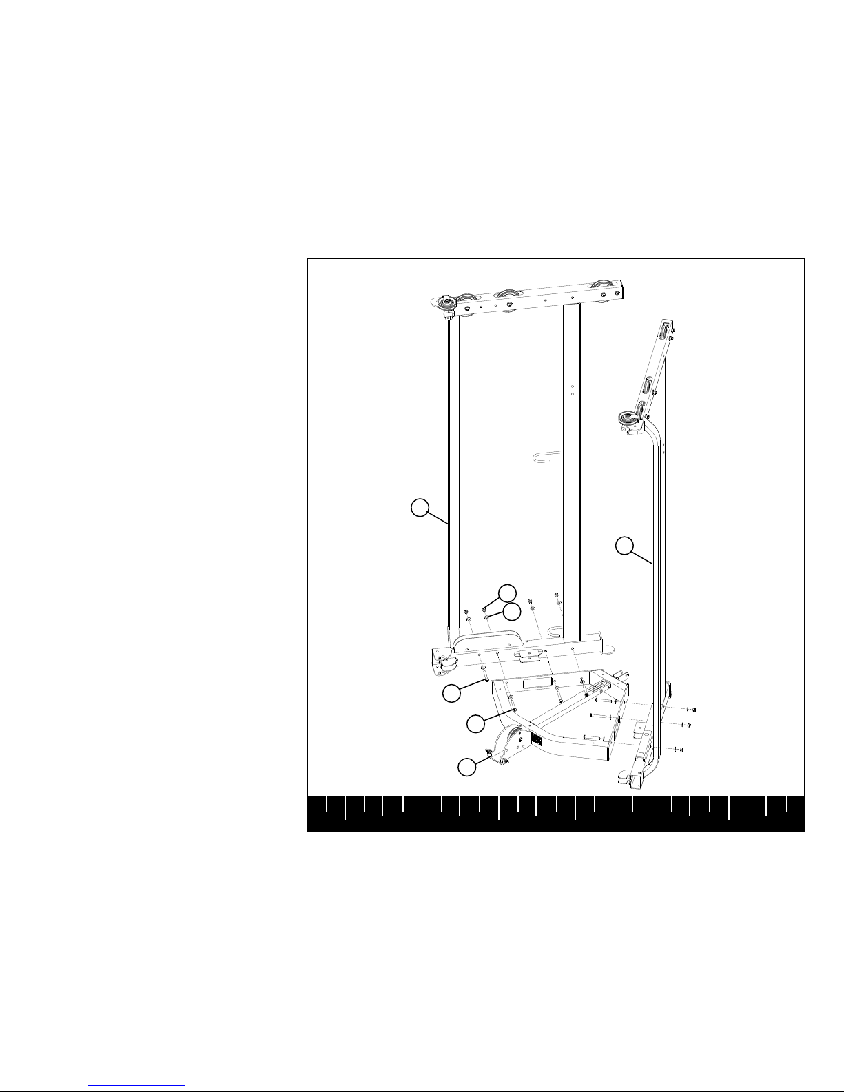
STEP 1
LOOSELY assemble the RIGHT SIDE (2) to
the BASE (1) using:
Three 3/8 X 2-3/4” BOLTS (13)
One 3/8 X 2-1/2” BOLT (15)
Eight 3/8” WASHERS (29)
Four 3/8” LOCK NUTS (25)
LOOSELY assemble the LEFT SIDE (3) to the
BASE (1) using:
Three 3/8 X 2-3/4” BOLTS (13)
Six 3/8” WASHERS (29)
Three 3/8” LOCK NUTS (25)
3/8 X 2-1/2” 15
3/8 X 2-3/4” 13
1
2
3
29
25
Page 8
1 2 3 4 5 6
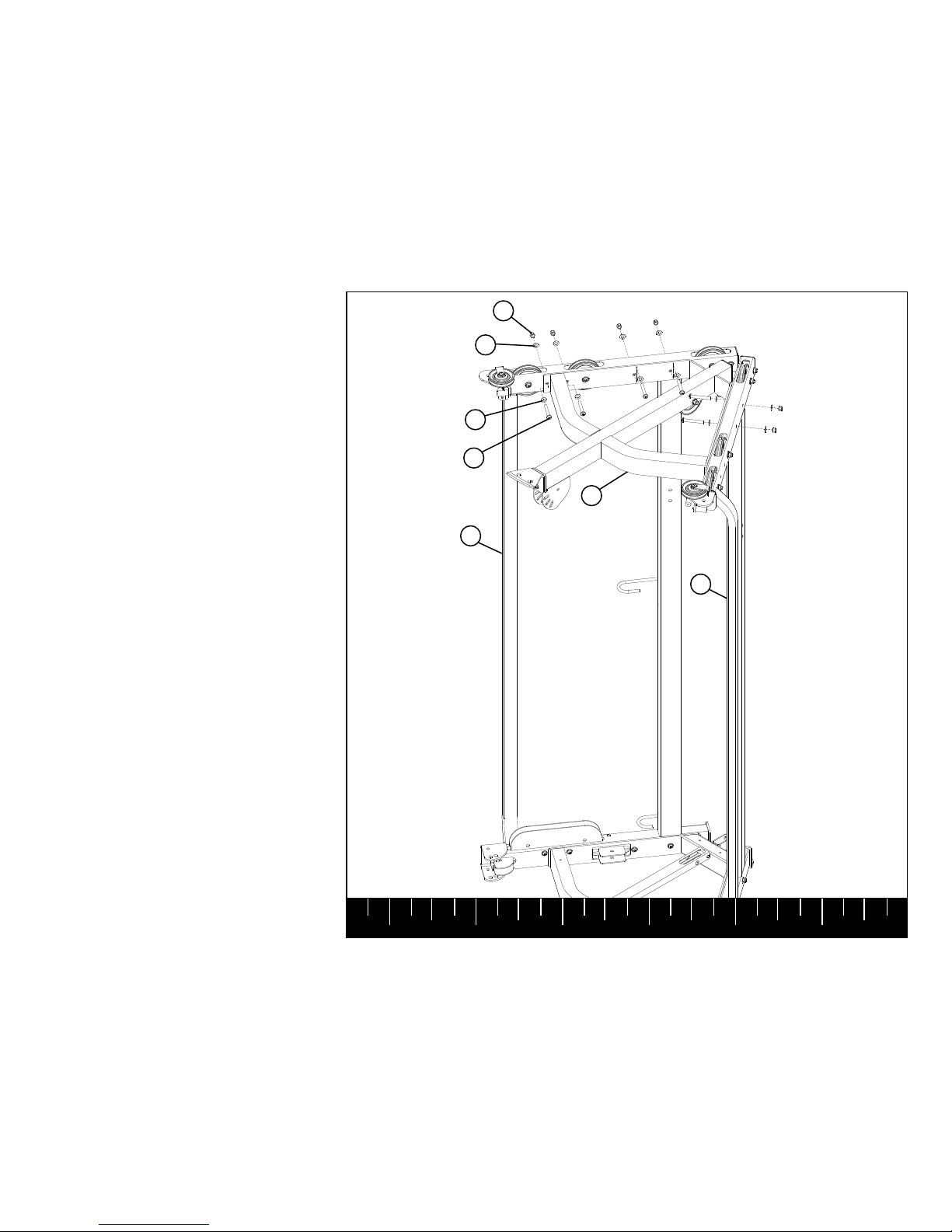
STEP 2
LOOSELY assemble the TOP BOOM (33)
between the RIGHT and LEFT SIDES (2 & 3)
using:
Six 3/8 X 2-3/4” BOLTS (13)
Twelve 3/8” WASHERS (29)
Six 3/8” LOCK NUTS (25)
29
25
3/8 X 2-3/4” 13
33
29
2
3
Page 9
1 2 3 4 5 6
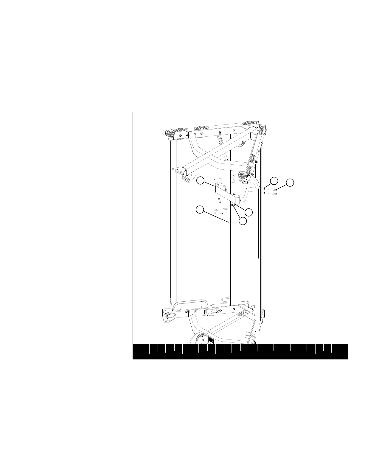
STEP 3
LOOSELY assemble the UPRIGHT SUPPORT
PLATE (34) between the rear tubes of the
RIGHT and LEFT SIDES (2 & 3) using:
Four 3/8 X 2-3/4” BOLTS (13)
Eight 3/8” WASHERS (29)
Four 3/8” LOCK NUTS (25)
SECURELY TIGHTEN ALL LOOSE FRAME
CONNECTIONS MADE TO THIS POINT.
34
2
29
25
29
13 3/8 X 2-3/4”
Page 10
1 2 3 4 5 6
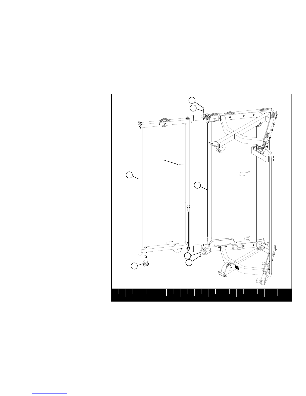
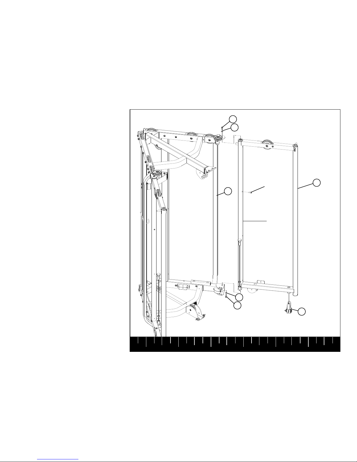
STEP 4
Insert one WHEEL SUPPORT (37) into the
bushing on the bottom of the RIGHT DOOR
(36) as shown.
LOOSELY assemble the RIGHT DOOR (36) to
the RIGHT SIDE (2) using:
Two 3/8 X 3/4” BOLTS W/NP (19)
Two 3/8” WASHERS (29)
Remove and discard RETAINING BOLT as
shown.
SECURELY tighten top and bottom BOLTS
simultaneously.
(NOTE: If the top and bottom BOLTS are
tightened before the RETAINING BOLT is
removed, the RETAINING BOLT may bind in
the shaft making removal difficult.)
37
2
36
29
29
3/8 X 3/4” 19
3/8 X 3/4” 19
RETAINING
BOLT
Remove and discard
BEFORE tightening
top and bottom bolts..
Do not rotate door
before removing!
Page 11
1 2 3 4 5 6
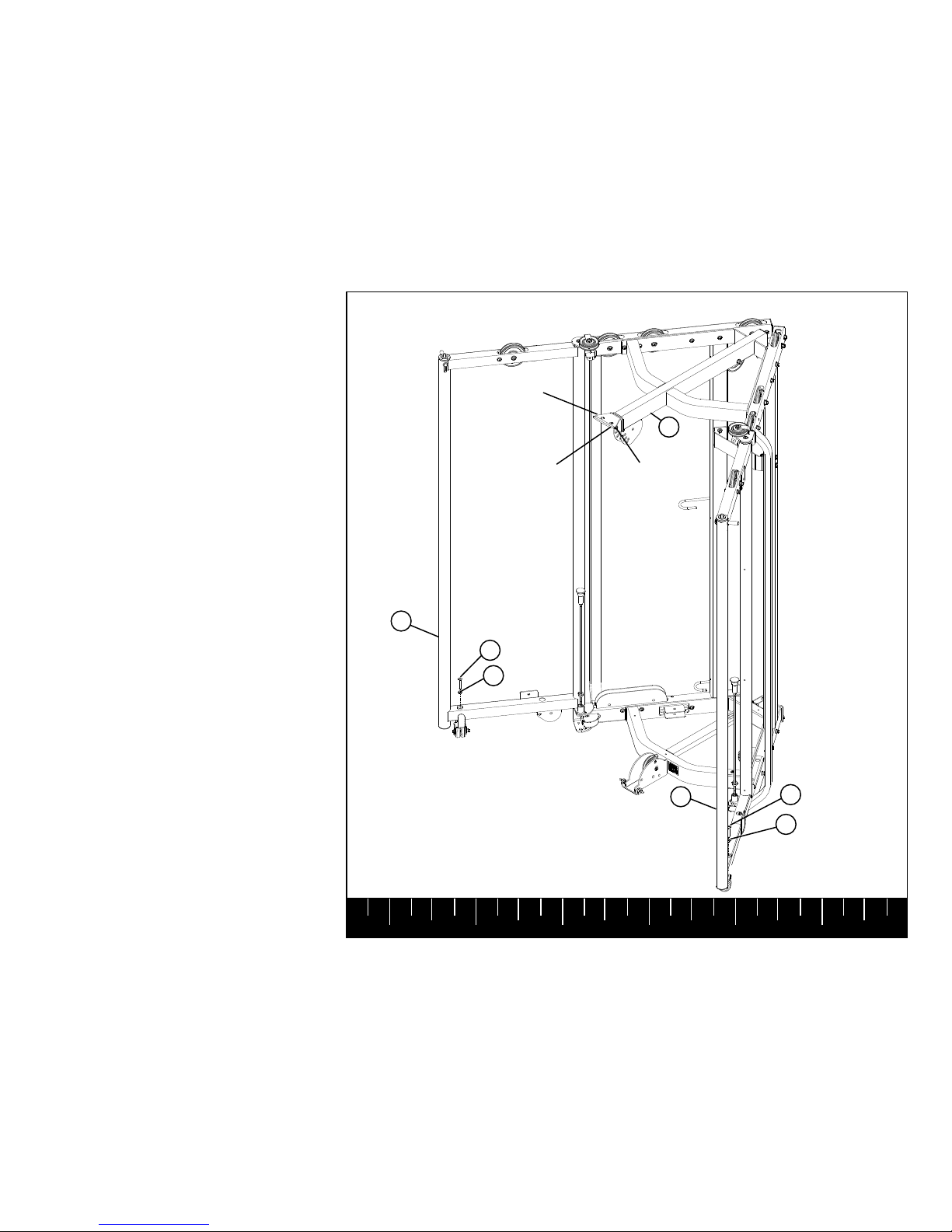
STEP 5
Insert one WHEEL SUPPORT (37) into the
bushing on the bottom of the LEFT DOOR (38)
as shown.
LOOSELY assemble the LEFT DOOR (38) to
the LEFT SIDE (3) using:
Two 3/8 X 3/4” BOLTS W/NP (19)
Two 3/8” WASHERS (29)
Remove and discard RETAINING BOLT as
shown.
SECURELY tighten top and bottom BOLTS
simultaneously.
(NOTE: If the top and bottom BOLTS are
tightened before the RETAINING BOLT is
removed, the RETAINING BOLT may bind in
the shaft making removal difficult.)
29
19 3/8 X 3/4”
19 3/8 X 3/4”
37
29
3
38
RETAINING
BOLT
Remove and discard
BEFORE tightening
top and bottom bolts..
Do not rotate door
before removing!
Page 12
1 2 3 4 5 6
STEP 6
To level the RIGHT and LEFT DOORS (36 &
38), thread one 3/8 X 2” BUTTON HEAD BOLT
(17) and one 3/8” JAM NUT (26) into the top of
the bushing on the RIGHT DOOR (36).
Turn the bolt clockwise until the wheel touches
the floor and the door is able to rotate in and out
smoothly.
Once the door is level, thread the jam nut down
to the top of the bushing, and tighten SE-
CURELY.
Note: the door may need to be re-leveled
from time to time. If this happens, simply
loosen jam nut, turn the bolt clockwise or
counterclockwise until level. Retighten jam
nut.
Repeat the above step for the LEFT DOOR
(38) as shown.
After the LEFT and RIGHT DOORS (36 & 38)
have been assembled release Spring Pins and
close DOORS. The DOORS should completely
lock into the DOOR LOCK ANGLE of the TOP
BOOM (33). If the Spring Pins do not lock in
place, loosen the two BUTTON HEAD BOLTS,
reposition the ANGLE until the DOORS lock
completely, and then retighten bolts.
17 3/8 X 2”
17 3/8 X 2”
38
26
26
36
DOOR LOCK
ANGLE
BUTTON
HEAD
BOLT
33
ADJUSTMENT
Page 13
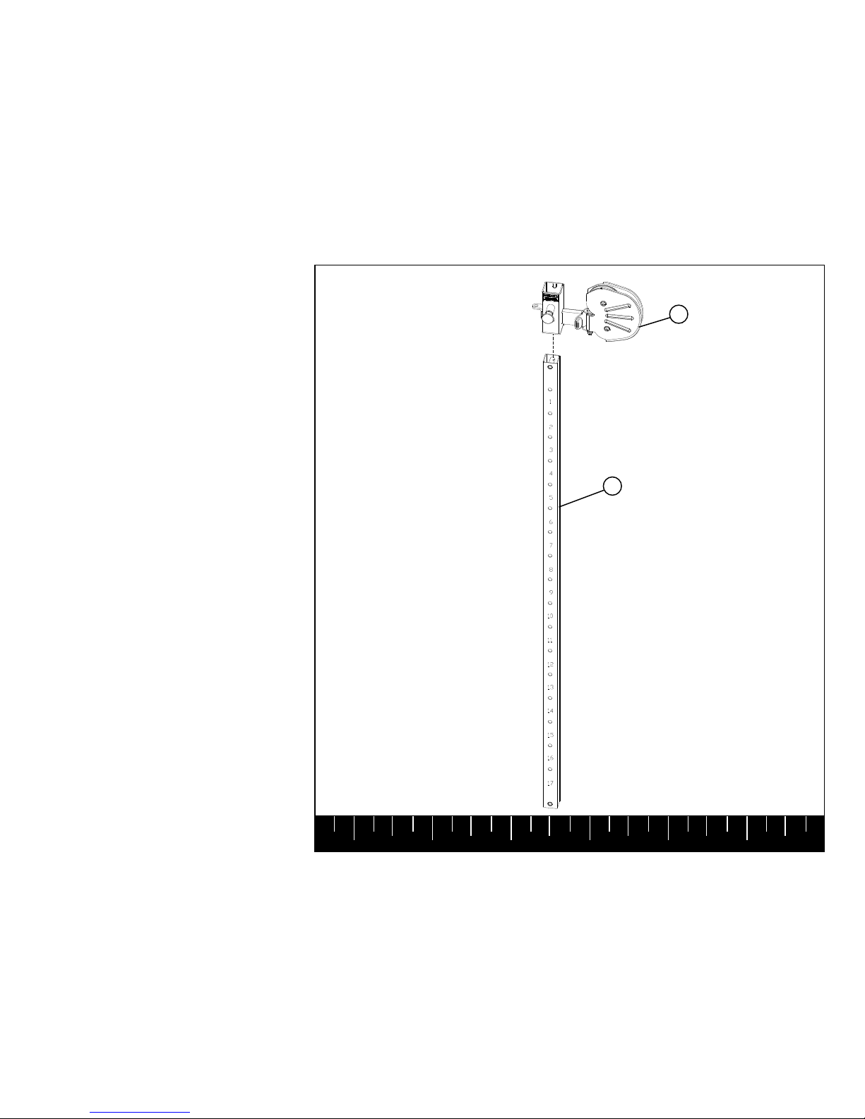
1 2 3 4 5 6
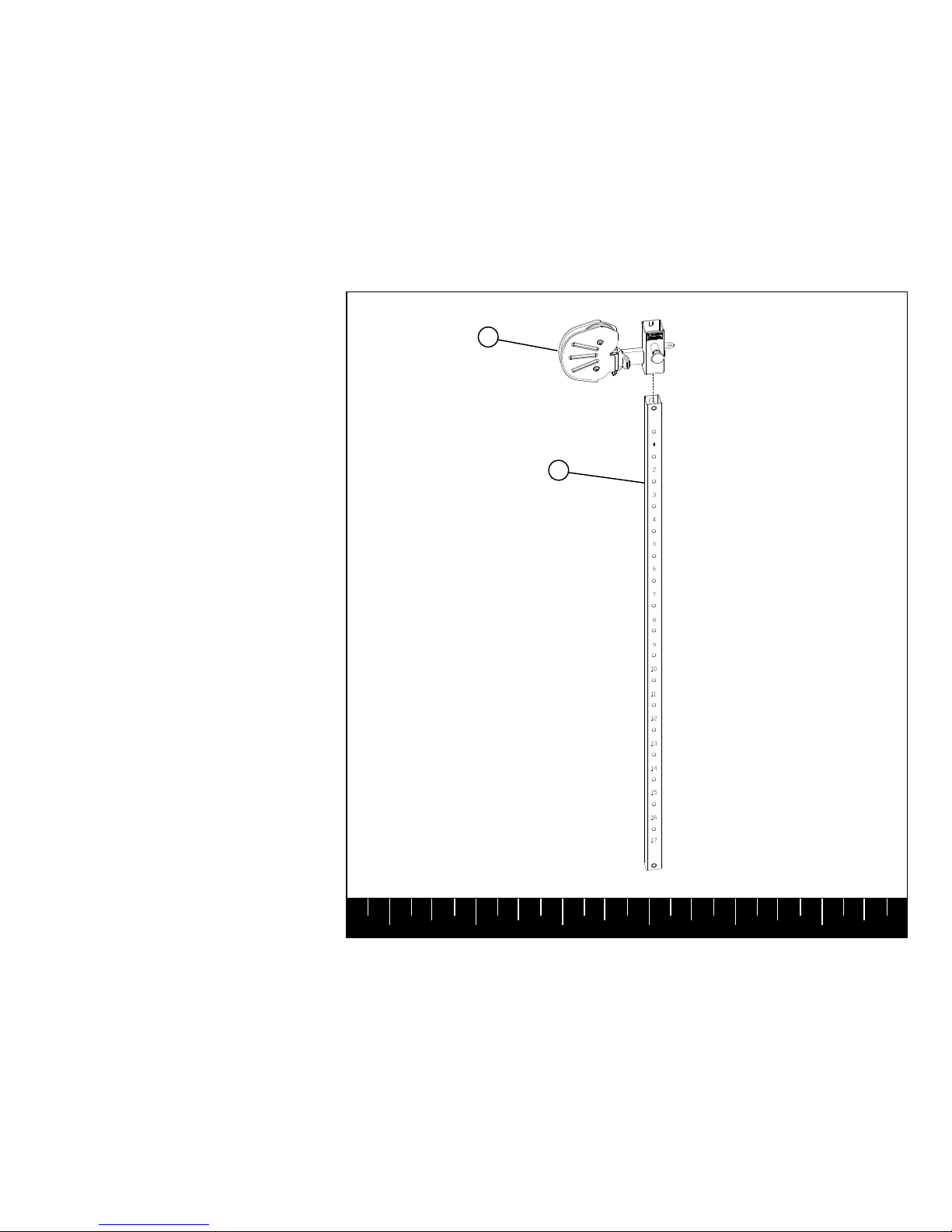
STEP 7
Pull back spring pin on the RIGHT SLIDE (40)
and CAREFULLY slide assembly over the end
of the SLIDE UPRIGHT (39). Release spring
pin into tenth hole on the SLIDE UPRIGHT
(39).
Note: Ensure numbers on the Slide Upright
show through the hole in Slide. Make sure
Spring Pin is fully engaged into the holes of
the Slide Upright.
39
40
Page 14
1 2 3 4 5 6
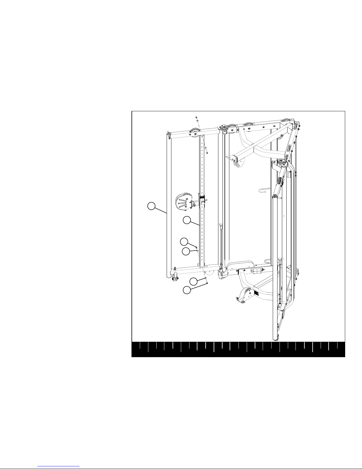
STEP 8
SECURELY assemble the SLIDE UPRIGHT
(39) to the RIGHT DOOR (36) using:
Two 3/8 X 2-3/4” BOLTS (13)
Four 3/8” WASHERS (29)
Two 3/8” LOCK NUTS (25)
Note: make sure the numbers on the SLIDE
UPRIGHT are facing in towards the machine.
3/8 X 2-3/4” 13
29
29
25
39
36
Page 15
1 2 3 4 5 6
STEP 9
41
39
Pull back spring pin on the LEFT SLIDE (41)
and CAREFULLY slide assembly over the end
of the SLIDE UPRIGHT (39). Release spring
pin into tenth hole on the SLIDE UPRIGHT
(39).
Note: Ensure numbers on the Slide Upright
show through the hole in Slide. Make sure
Spring Pin is fully engaged into the holes of
the Slide Upright.
 Loading...