

Page 1
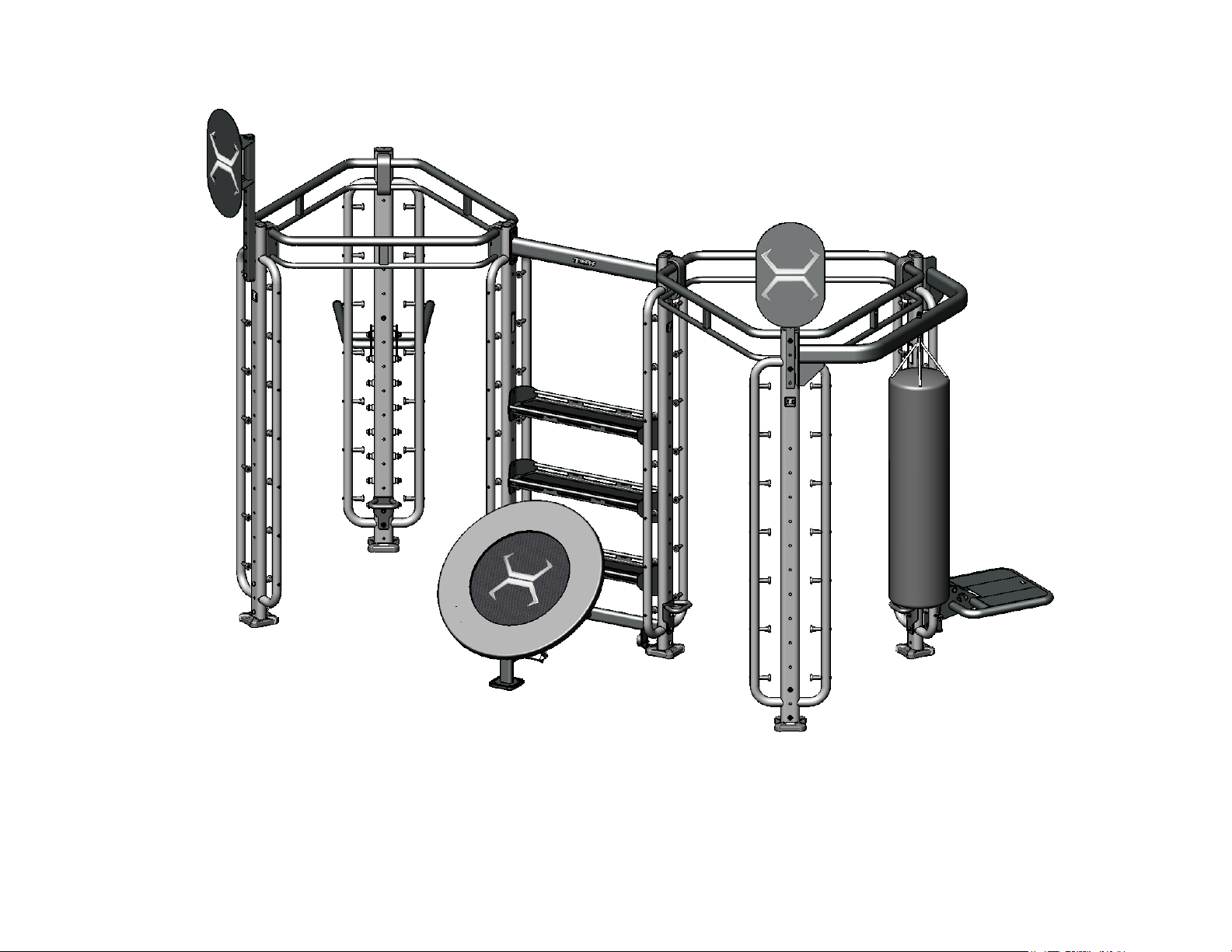
X-LAB-SPIDER 2
Assembly Guide
VERSION: XLS2-X1
PART #: 5519101-A
Page 2
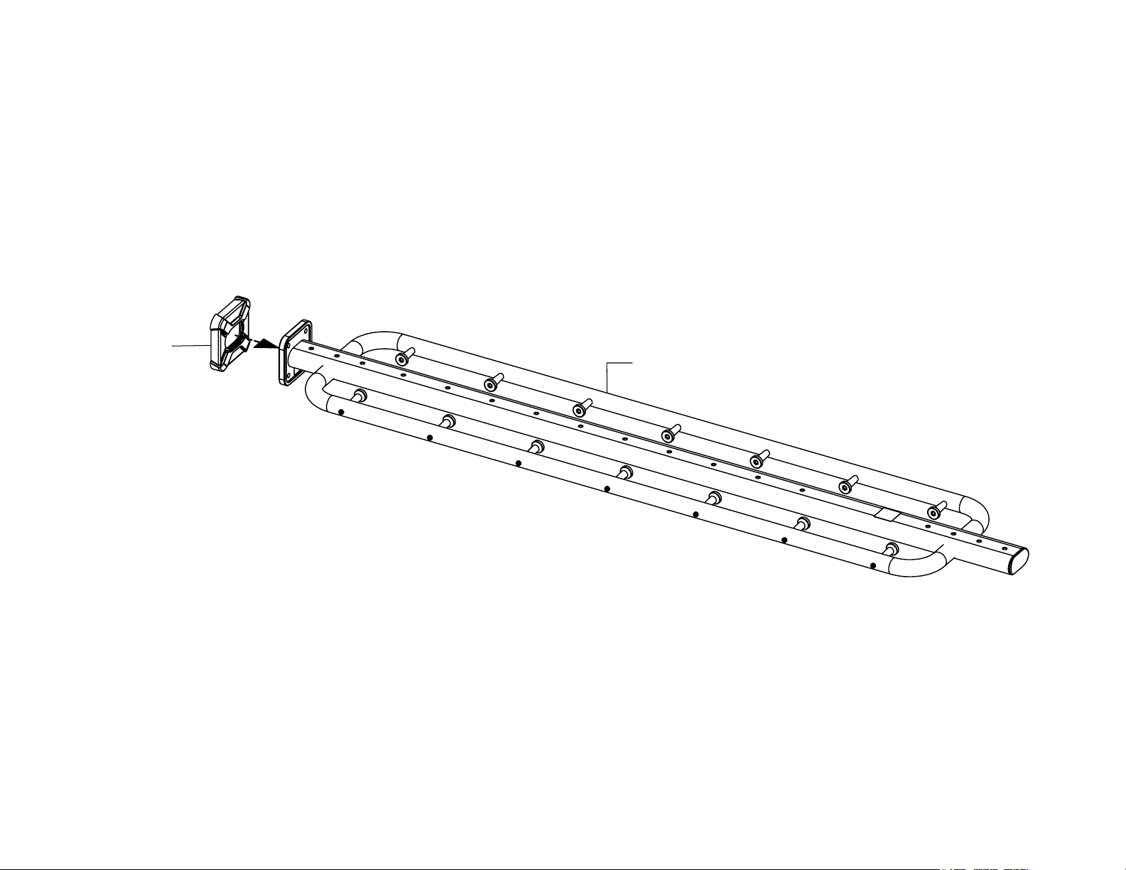
STEP 1
XLAB-BOOT
XLAB-301
NOTE:
Repeat this step for remaining XLAB 301 uprights.
PAGE 2
Page 3
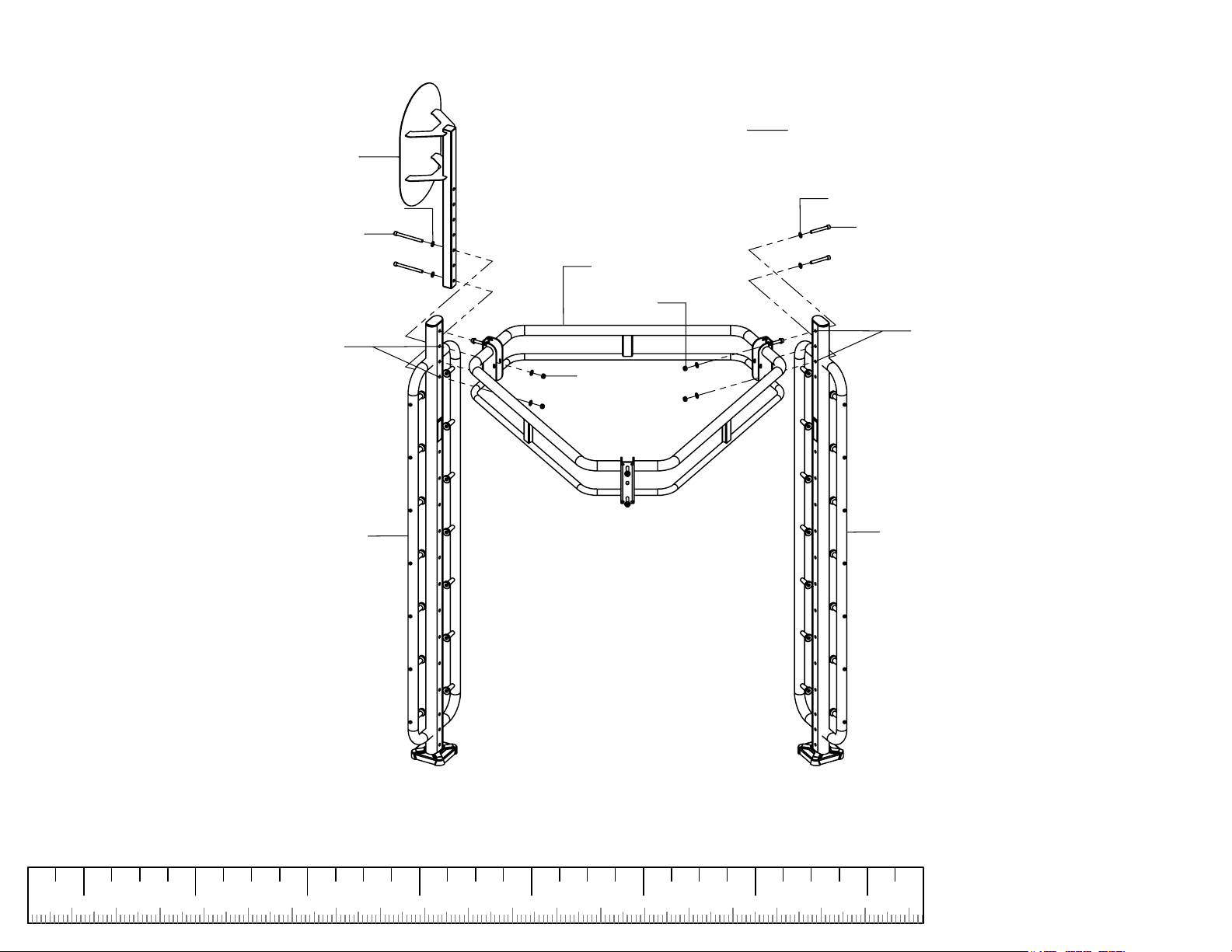
STEP 2
HSA-101
BT-103
1/2" FLAT WASHER (4)
1/2 X 5-3/4" BOLT (2)
NOTE:
Assemble to second
and fourth holes.
XLAB-301
1/2" FLAT WASHER (4)
1/2 X 3-3/4" BOLT (2)
XLAB-101
1/2" LOCK
NUT (2)
NOTE:
Assemble to first
and third holes.
1/2" LOCK
NUT (2)
XLAB-301
NOTE:
For ease of assembly, assemble this step on the floor.
LOOSELY
assemble bolt connections in this step.
1 2 4 5 7
50 1803190150 170160
130 14012090 110100403010 706020 80
6
200
PAGE 3
Page 4
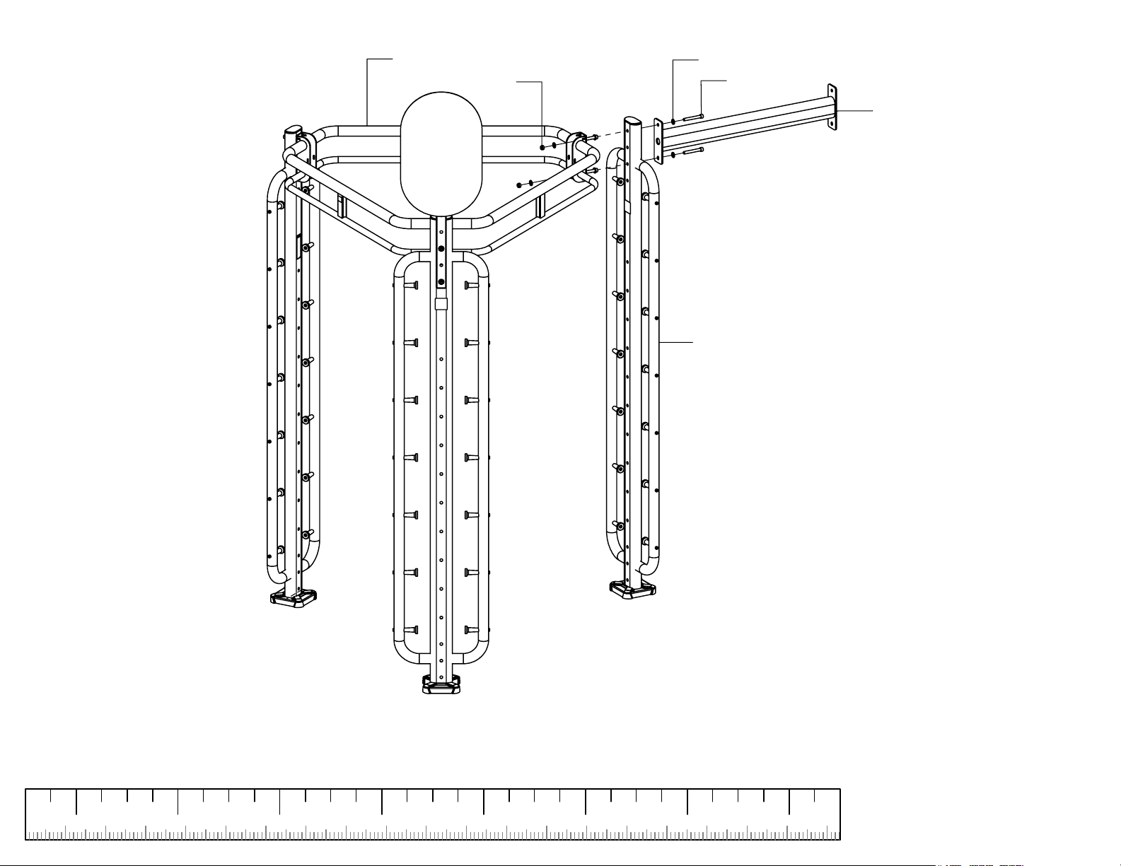
STEP 3
XLAB-101
1/2" LOCK NUT (2)
1/2" FLAT WASHER (4)
1/2 X 3-3/4"
BOLT (2)
XLAB-401
XLAB-301
NOTE: CAREFULLY
with this step.
LOOSELY
assemble bolt connections in this step.
1 2 4 5 7
turn machine right side up before proceeding
50 1803190150 170160
130 14012090 110100403010 706020 80
6
200
PAGE 4
Page 5
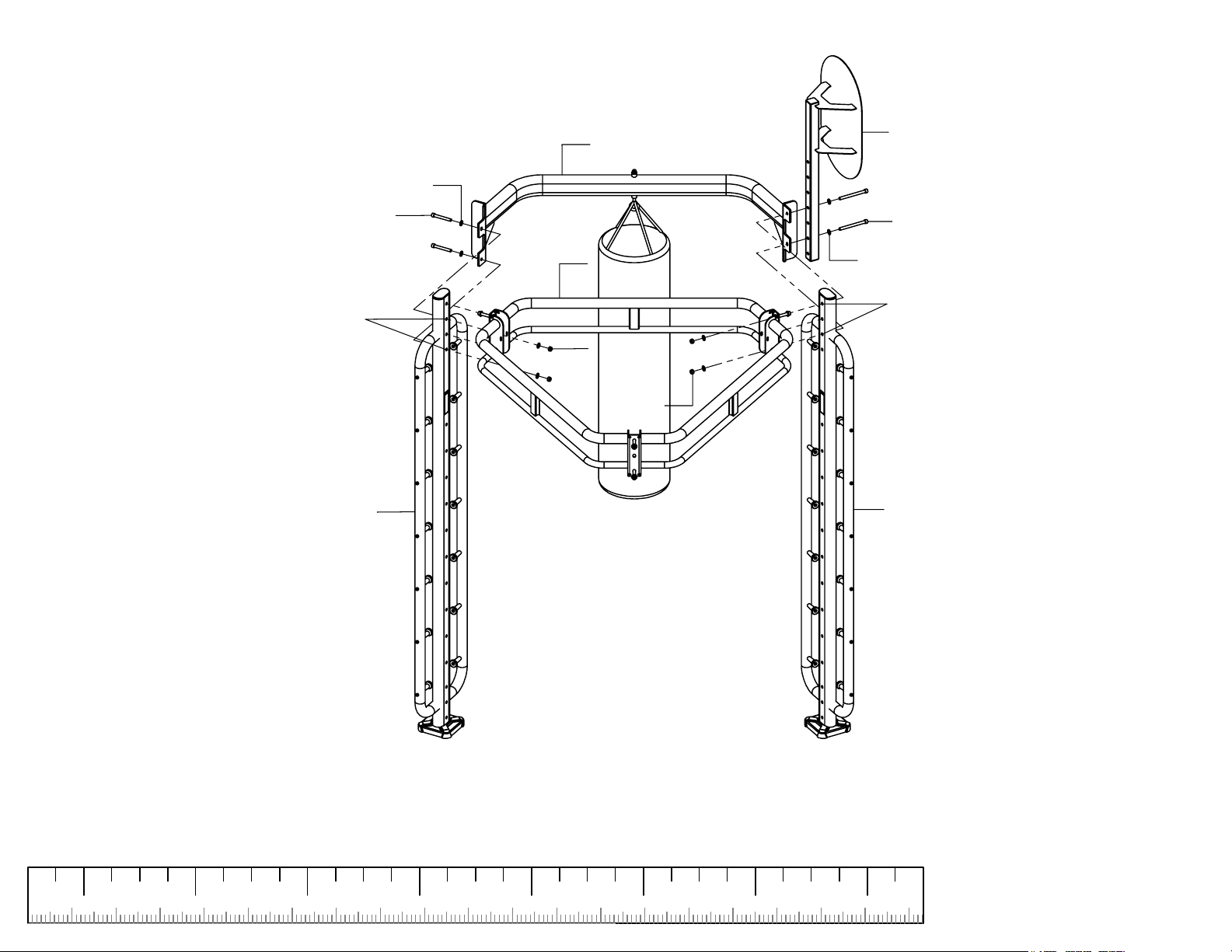
STEP 4
1/2" FLAT WASHER (4)
1/2 X 3-3/4" BOLT (2)
NOTE:
Assemble to second
and fourth holes.
XLAB-301
HBA-101
XLAB-101
1/2" LOCK
NUT (2)
1/2" LOCK
NUT (2)
BT-103
1/2 X 5-3/4" BOLT (2)
1/2" FLAT WASHER (4)
NOTE:
Assemble to first
and third holes.
XLAB-301
NOTE:
For ease of assembly, assemble this step on the floor.
LOOSELY
assemble bolt connections in this step.
1 2 4 5 7
50 1803190150 170160
130 14012090 110100403010 706020 80
6
200
PAGE 5
Page 6
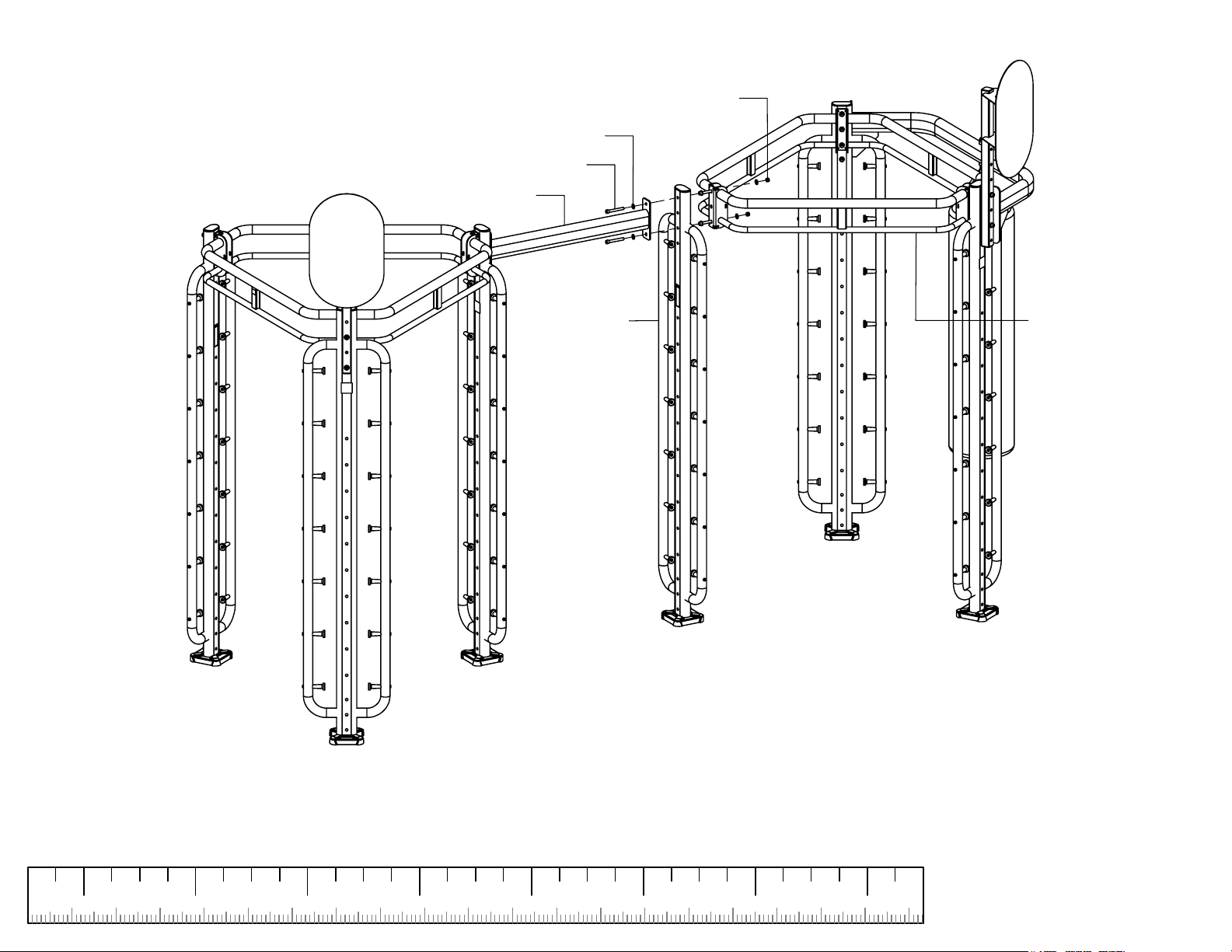
STEP 5
1/2" LOCK NUT (2)
1/2" FLAT WASHER (4)
1/2 X 3-3/4" BOLT (2)
XLAB-401
XLAB-301
XLAB-101
NOTE: CAREFULLY
with this step.
LOOSELY
assemble bolt connections in this step.
1 2 4 5 7
turn machine right side up before proceeding
50 1803190150 170160
130 14012090 110100403010 706020 80
6
200
PAGE 6
Page 7
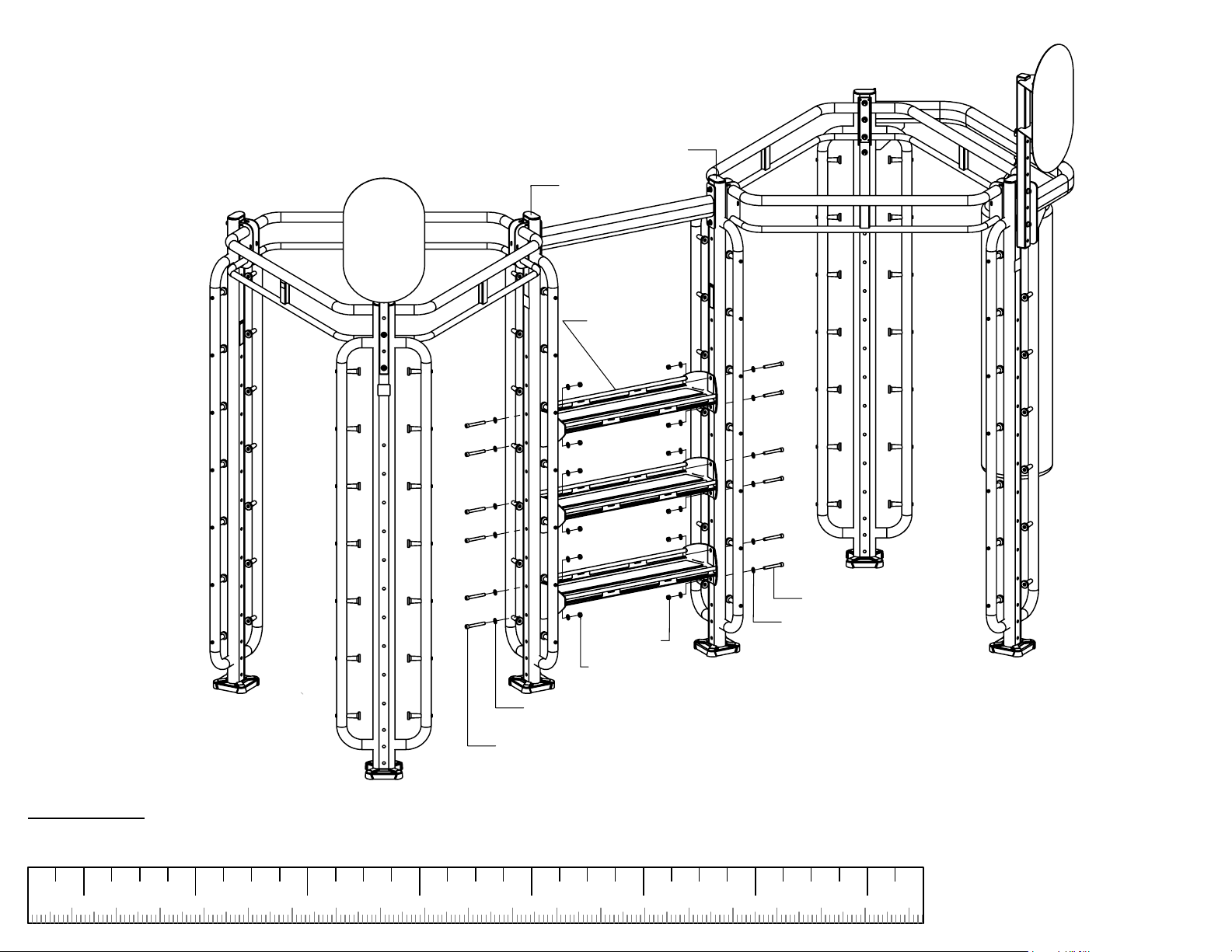
STEP 6
XLAB-301
XLAB-301
AT-101 (3)
ATTENTION:
After this step has been assembled,
SECURELY
tighten
all bolt connections from this step and previous steps.
1 2 4 5 7
50 1803190150 170160
1/2" LOCK
NUT (6)
1/2" LOCK
NUT (6)
1/2" FLAT
WASHER (12)
1/2 X 3-3/4" BOLT (6)
130 14012090 110100403010 706020 80
1/2 X 3-3/4" BOLT (6)
1/2" FLAT
WASHER (12)
6
200
PAGE 7
Page 8
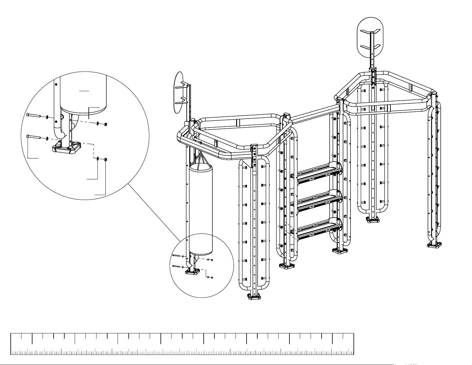
STEP 7
XLAB-301
GRT-101
1/2 X 3-3/4"
BOLT (2)
1/2" FLAT
WASHER (4)
1/2" LOCK
NUT (2)
SECURELY
assemble all bolt connections in this step.
1 2 4 5 7
50 1803190150 170160
130 14012090 110100403010 706020 80
6
200
PAGE 8
Page 9
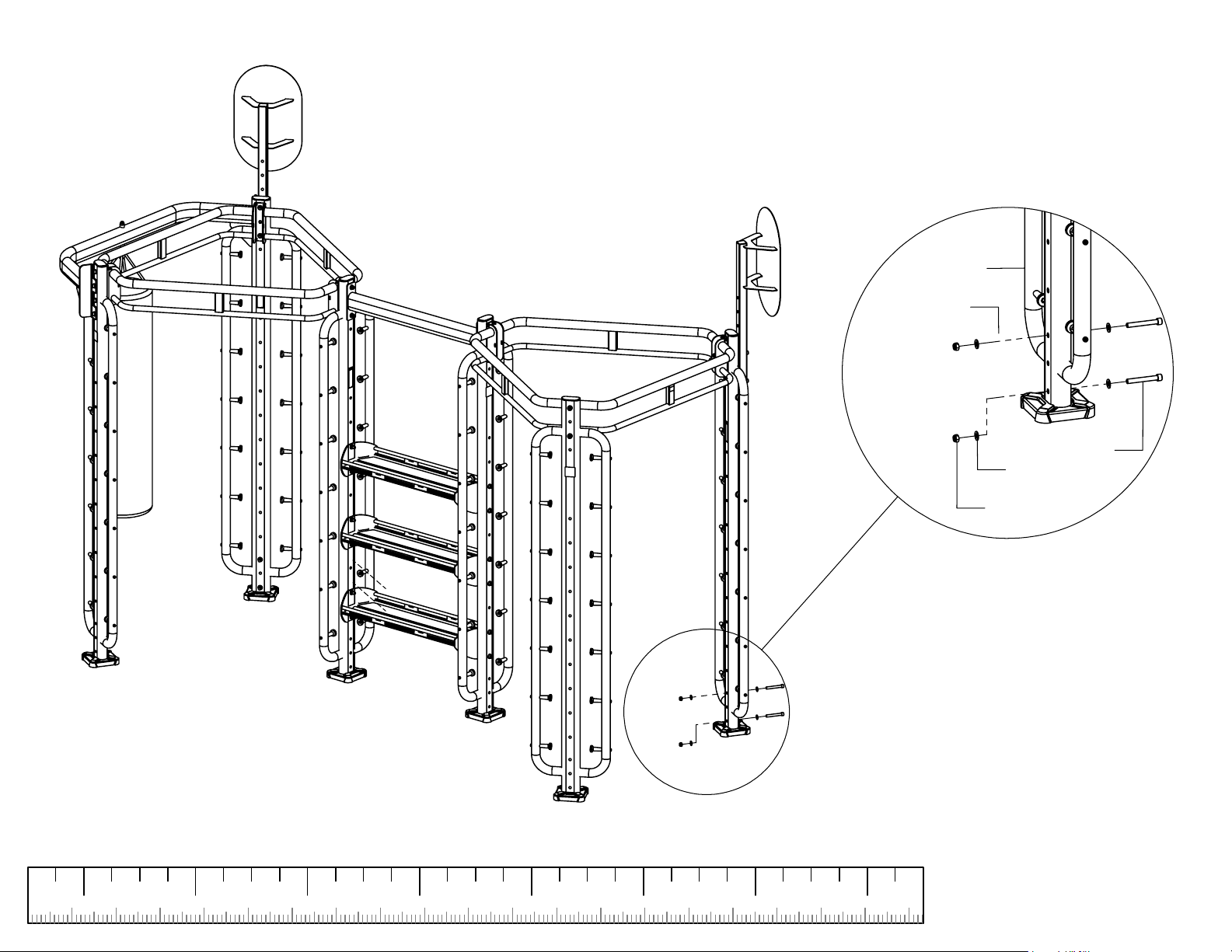
STEP 8
XLAB-301
GRT-101
1/2 X 3-3/4"
BOLT (2)
1/2" FLAT
WASHER (4)
1/2" LOCK
NUT (2)
SECURELY
assemble all bolt connections in this step.
1 2 4 5 7
50 1803190150 170160
130 14012090 110100403010 706020 80
6
200
PAGE 9
Page 10
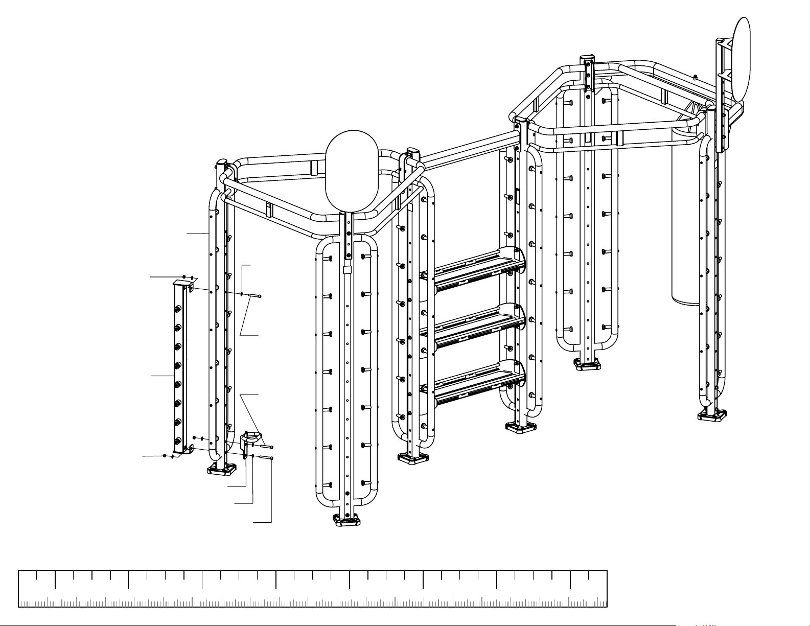
STEP 9
XLAB-301
1/2" LOCK NUT
1/2" FLAT
WASHER (2)
XLAB-AA-101
1/2"LOCK NUT (2)
SECURELY
1/2 X 3-1/4"
BOLT
1/2 X 3-1/4"
BOLT
SU-101
1/2" FLAT WASHER (4)
1/2 X 3-1/2" BOLT
assemble all bolt connections in this step.
1 2 4 5 7
50 1803190150 170160
130 14012090 110100403010 706020 80
6
200
PAGE 10
Page 11
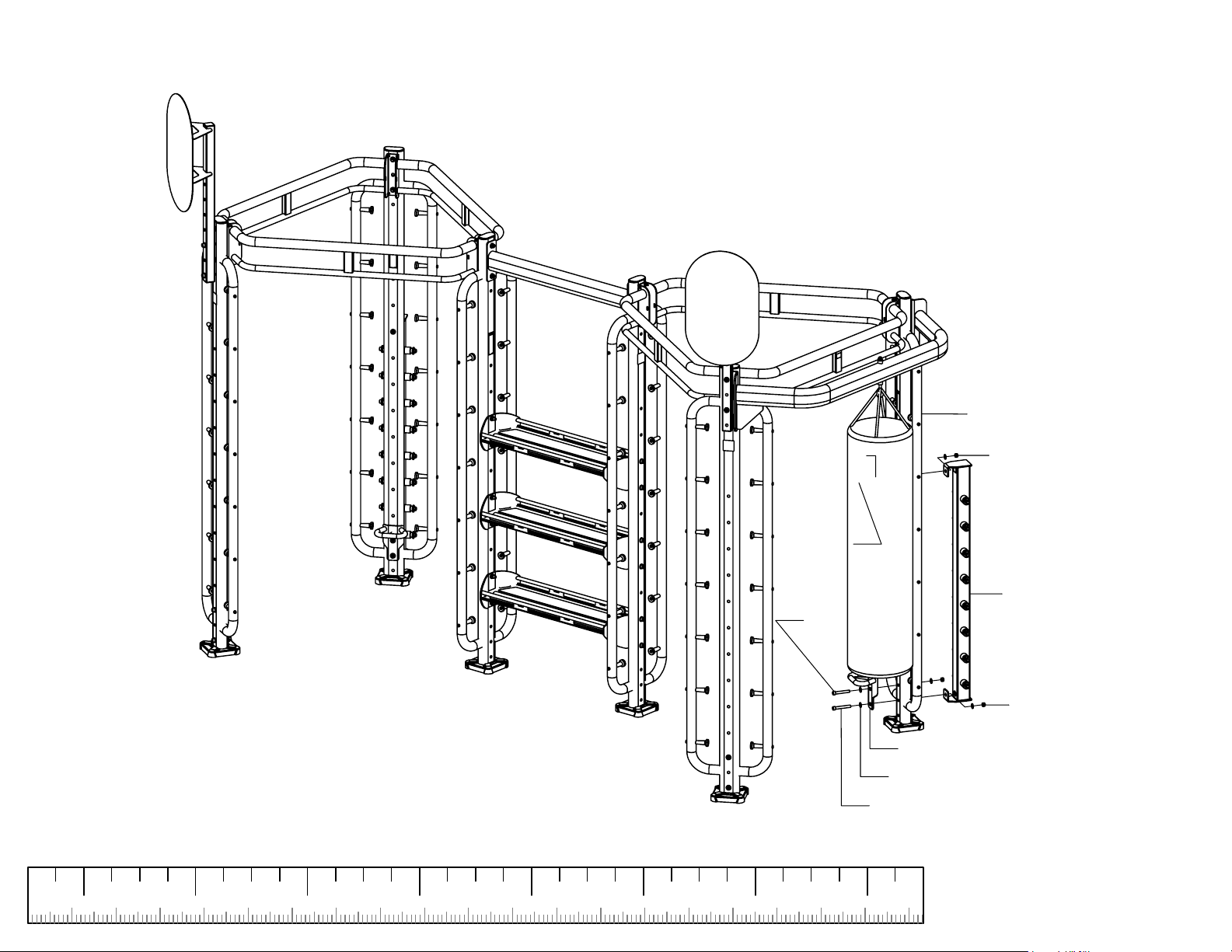
STEP 10
1/2" FLAT
WASHER (2)
XLAB-301
1/2" LOCK NUT
SECURELY
1/2 X 3-1/4"
BOLT
assemble all bolt connections in this step.
1 2 4 5 7
50 1803190150 170160
130 14012090 110100403010 706020 80
6
XLAB-AA-101
1/2 X 3-1/4"
BOLT
1/2" LOCK NUT (2)
SU-101
1/2" FLAT WASHER (4)
1/2 X 3-1/2" BOLT
200
PAGE 11
Page 12
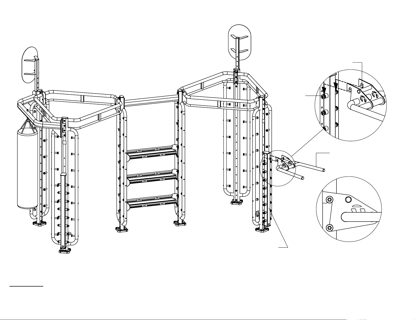
STEP 11
HOOKS
PEGS
XLAB-DA-101
WARNING!
MAKE SURE THAT BOTH HOOKS OF DIP ATTACHMENT ARE
SEATED SECURELY IN GROOVES OF PEGS ON ATTACHMENT
ANCHOR BEFORE PERFORMING ANY EXERCISES.
XLAB-AA-101
ASSEMBLED VIEW
PAGE 12
Page 13
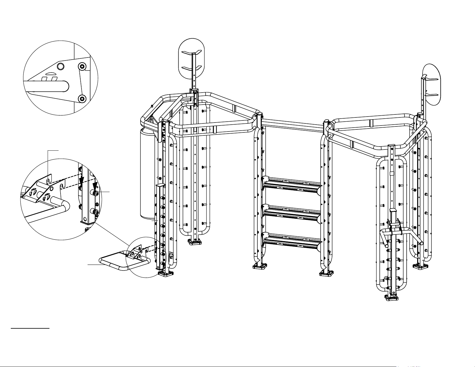
STEP 12
ASSEMBLED VIEW
HOOKS
PEGS
XLAB-AA-101
XLAB-PS-101
WARNING!
MAKE SURE THAT BOTH HOOKS OF PLYO STEP ARE SEATED
SECURELY IN GROOVES OF PEGS ON ATTACHMENT ANCHOR
BEFORE PERFORMING ANY EXERCISES.
PAGE 13
Page 14
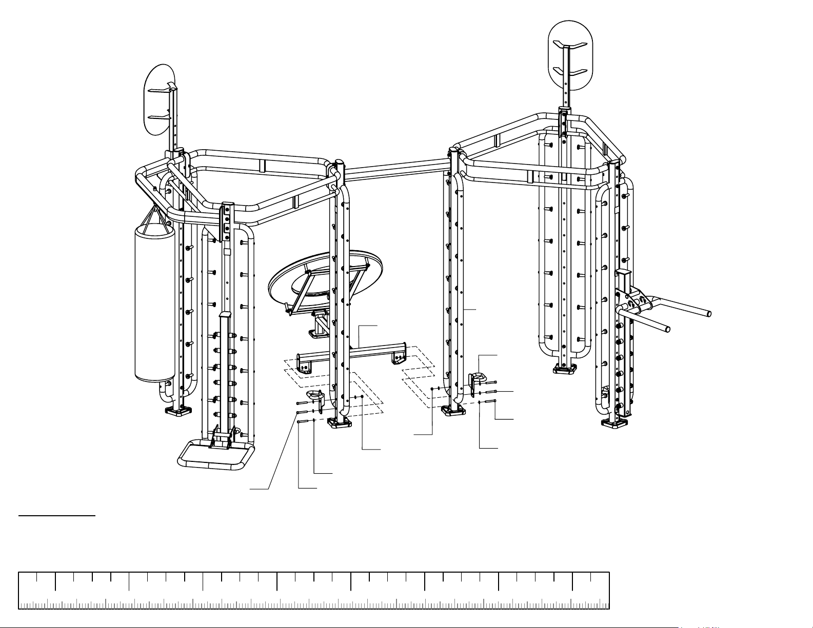
STEP 13
XLAB-301
BR-101
1/2 X 3-1/4" BOLT W/NP
ATTENTION:
COMPLETELY ASSEMBLE
THE
XLAB
SECURELY
.
assemble all bolt connections in this step.
1 2 4 5 7
50 1803190150 170160
BR-101
1/2" LOCK
NUT (2)
1/2" LOCK
NUT (2)
1/2" FLAT WASHER (5)
1/2 X 3-1/4" BOLT (2)
BEFORE ASSEMBLING IT TO
130 14012090 110100403010 706020 80
SU-101
1/2 X 3-1/4"
BOLT W/NP
1/2 X 3-1/4"
BOLT (2)
1/2" FLAT
WASHER (5)
6
200
PAGE 14
Page 15
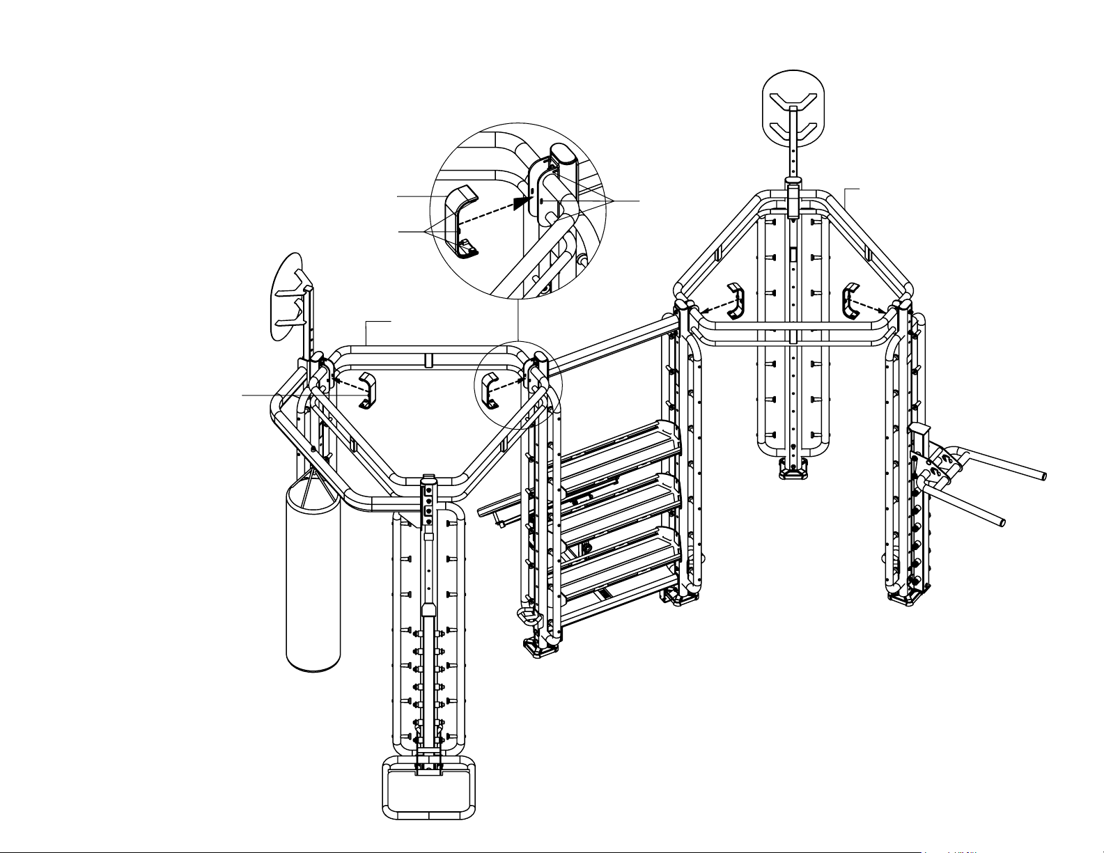
STEP 14
NOTE:
MAKE SURE TABS OF
INSERTED INTO GROOVES OF BRACKET ON
XLAB-101
(6 PLACES)
BRACKET COVERS
ARE
BRACKET COVER (6)
BRACKET COVER
TABS
GROOVES
XLAB-101
XLAB-101
PAGE 15
Page 16
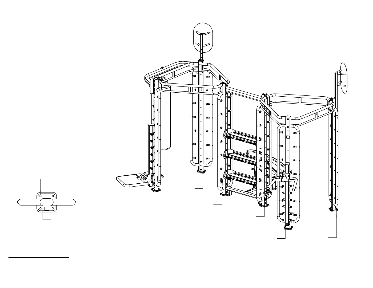
ANCHOR STEPS:
1) Position machine in desired location.
2) Trace around the four base plates and
the four holes in each base plate.
3) Move machine.
4) Drill anchor holes. Follow instructions
on anchor bolt packaging.
5) Vacuum dust out of each anchor hole.
6) Move machine back over anchor holes.
7) Anchor machine. Follow instructions on
anchor bolt packaging.
ANCHOR
HOLES (4)
ANCHOR
HOLES (4)
BASE
PLATE
ANCHOR
HOLES (4)
WARNING!
ALL X-LABS ARE REQUIRED TO BE ANCHORED TO THE
FLOOR TO PREVENT ROCKING OR TIPPING DURING USE.
ANCHOR
HOLES (4)
ANCHOR
HOLES (4)
ANCHOR
HOLES (4)
ANCHOR
HOLES (4)
PAGE 16
 Loading...