

TorqSense ORT230-C, ORT240-C, ORT230-D, ORT240-E, ORT230-F User Manual
...
ORT230/240 SERIES
TRANSDUCER
USER MANUAL
CAUTION
This instruction manual should be read carefully and the
safety instructions observed before installing or operating
the equipment related to this manual.
Apollo Park, Ironstone Lane, Wroxton, Banbury
Oxon, OX15 6AY
Tel: +44 (0)1869 238400 Fax: +44 (0)1869 238401
Email: info@sensors.co.uk Web: www.sensors.co.uk

Sensor Technology 2016 Page 1 ORT4076IM (Rev 1)
While every precaution has been exercised in the compilation of this document to ensure the
accuracy of its contents, Sensor Technology Ltd, assumes no responsibility for any errors or
omissions. Additionally, no liability is assumed for any damages that may result from the use
of the information contained in this document.
Copyright
Copyright 2016 Sensor Technology Ltd. All rights Reserved.
Copying or reproducing of all or any part of the contents of this manual is strictly prohibited
without the express permission of Sensor Technology.
Trademarks
TorqSense is a registered trademark of Sensor Technology Ltd.
TorqView is a trademark of Sensor Technology Ltd.
LabVIEW is a trademark of National Instruments Corporation.
National Instruments is a trademark of National Instruments Corporation.
Windows is a registered trademark of Microsoft Corporation.
Lifetime Warranty
Sensor Technology Ltd’s standard range of products are warranted against manufacturing
defects and component failure for two years from date of purchase, subject to fair wear and
tear and return for the first year's free of charge annual re-calibration. This warranty is
extended indefinitely if the equipment is returned to Sensor Technology, or its distributor, for
annual re-calibration, when software and hardware updates, if required, will be carried out
free of charge. Standard range means those products as described in the company's product
data sheets.

Sensor Technology 2016 Page 2 ORT4076IM (Rev 1)
Table of Contents
Getting Started......................................................................................................................... 3
Introduction............................................................................................................................ 3
Unpacking the transducer ..................................................................................................... 3
Mechanical Installation .......................................................................................................... 4
Operating Principles .............................................................................................................. 5
Operation.................................................................................................................................. 6
Powering the transducer ....................................................................................................... 6
Using the transducer ............................................................................................................. 6
Built In Test (BIT) .................................................................................................................. 7
Normal Operation .................................................................................................................. 8
Peak Mode........................................................................................................................ 8
Analog Scaling..................................................................................................................8
Warning Signals .................................................................................................................... 9
Error Signals........................................................................................................................ 10
Peak Input ........................................................................................................................... 10
Analog Output.................................................................................................................10
Peak Reset .....................................................................................................................10
Analog Outputs.................................................................................................................... 11
Data Assignments........................................................................................................... 11
Voltage/Current Assignments......................................................................................... 12
Fail Output........................................................................................................................... 12
Limit Output ......................................................................................................................... 13
Zeroing the transducer ........................................................................................................ 14
Electrical Signal .............................................................................................................. 14
Digital Command ............................................................................................................ 15
Resetting transducer to factory default ............................................................................... 15
Examples of reading/collecting data ................................................................................... 16
Optional Accessories............................................................................................................ 17
Analog Lead ........................................................................................................................ 17
Digital Lead (ORT240
series ONLY)...................................................................................
17
Digital Adaptor Lead (ORT240 series ONLY) ..................................................................... 17
Additional Related Products and Transducer Resources................................................. 17
Transducer Display ETD ..................................................................................................... 17
Transducer Signal Breakout Unit ........................................................................................ 17
AC Mains Adaptor Power Supply........................................................................................ 17
TorqView (ORT240 series ONLY)....................................................................................... 17
Transducer Control Program (ORT240 series ONLY) ........................................................ 17
Transducer Communication Protocol (ORT240 series ONLY) ........................................... 17
Transducer DLL Programmers Guide (ORT240 series ONLY) .......................................... 17
Leads ...................................................................................................................................... 18
Analog Lead - Pin Out......................................................................................................... 18
Digital Lead - Pin Out (ORT240 Series ONLY)................................................................... 19
Transducer Connections ...................................................................................................... 20
Analog ................................................................................................................................. 20
Digital .................................................................................................................................. 20
Data Specification . . . . . . . Attached
Appendices (ORT240 series ONLY)
1. ORT240 Series Transducer Control Utility
Attachments (the following documents may also be attached)
1. TorqView User Guide

Sensor Technology 2016 Page 3 ORT4076IM (Rev 1)
Getting Started
Introduction
The Optical Rotary Torque Transducer provides a method of precisely
measuring bi-directional rotary or static torque. It can also be fitted with a speed sensor for
monitoring in dynamic applications, enabling direct measurements of transmitted power.
The ORT series transducers require no external instrumentation and has its own built in test
capability. Its compact size makes it ideal for use in applications where there is little space for
any extra equipment. Analog voltage outputs are standard, with current outputs available as
an option. The ORT240 series can also be connected to a PC via USB (optional) or RS232
so that its configuration can be changed, or by using TorqView to display torque, speed and
power.
Unpacking the transducer
The following standard components are included:
▪ 1 x ORT Series Transducer
▪ 1 x ORT Electronics Module
▪ 1 x User Manual
▪ 1 x Calibration Certificate
Additional components for ORT240 series:
▪ 1 x TorqView program installation USB flash drive, ORT Configuration Software,
Manuals & Appendices in PDF format, USB driver.
The following items may also be included:
▪ 12pin Lumberg (female) and/or 12pin Lumberg (male).
▪ 1 x 2.5m Analog Lead - 15 way ‘D’ type connector (female) to 12pin Lumberg
(female).
▪ 1 x 2.5m Digital Lead - 15 way ‘D’ type connector (male) to 12pin Lumberg (male).
(ORT240 series transducer ONLY).
▪ 1 x Digital Adaptor Lead (DC Jack with USB and/or RS232 connections, depending
on options requested) (ORT240 series transducer ONLY).
▪ 1 x Transducer Display ETD
▪ 1 x AC Mains Adaptor Power Supply.
▪ 1 x Transducer Signal Breakout Unit.
▪ 1 x Analog Dongle.
CAUTION
The ORT series transducers should not be operated at any torque load greater or
speed faster than that specified in the Product data sheet and on the Transducer.
CAUTION
The ORT series transducers should be installed using correct couplings rated for
the maximum torque and speed for the operation.
CAUTION
The ORT series transducers should not be operated in an environment where that
operation could be life threatening or a danger to personnel.
CAUTION
In electrically noisy environments, the ORT series transducers should be earthed
using the earthing post located on the transducer.

Sensor Technology 2016 Page 4 ORT4076IM (Rev 1)
Mechanical Installation
To obtain the best measurements from your torque transducer it is essential that it is
correctly installed.
To avoid damaging the transducer during the installation process it is highly recommended
that it is electrically connected and working so that any torque overloads applied due to
handling can be monitored.
For Transducers above 1Nm or 10lbf.in. it is recommended that the body of the
transducer is restrained from rotation using a strap or straps connected to the tapped holes
in the end plates and that it is not rigidly mounted. Couplings should be used to allow for
angular misalignment while the transducer shaft takes up any parallel misalignment. Care
should be taken not to induce any end loads or bending moments to the shaft, see below,
as these may induce inaccuracies to the torque measurement and in extreme cases
damage the transducer.
Should rapid variations in torque need to be measured in detail e.g.
torque fluctuations in gearboxes or multi vane pumps then it is
recommended using torsionally rigid couplings fitted at both ends of
the transducer shaft such as single membrane couplings and that
these are correctly selected for the transducer rating and speed.
An undersized coupling will not transmit the torque while the high
inertia of an oversized coupling can result in instantaneous peak
torques far in excess of the measured torque. Alternatively, for lower
bandwidth applications where it is more important to measure the
‘average’ torque rather than fast torque fluctuations then couplings
with a degree of compliance would be more appropriate.
Never use a solid coupling to connect a ORT series transducers
Torque Transducer
For Transducers below 1Nm or 10lbf.in or if the application
requires the body to be rigidly mounted then it is recommended that
double couplings should be used at each end to compensate for any
misalignment of the input/output shafts and the system designed to
eliminate any end loads on the transducer shaft. For applications
where end loads cannot be avoided please consult the sales
department for advice prior to ordering.
When using a pulley or pulleys it is recommended a bearing block or
blocks should be used to ensure bending loads are not transmitted to
the transducer.
Lastly, consider using a guard over the transducer and couplings
Single membrane
coupling
(
Flexible mountin
g)
Double membrane
coupling
(Rigid mounting)

Sensor Technology 2016 Page 5 ORT4076IM (Rev 1)
Whilst the transducer is resistant to EMC interference to BS EN 61326-1:2006, the
sensible routing of cables is important to avoid possible EMC interference. Avoid
running the transducer cables close, and/or parallel, to high voltage cables, solenoid
valves, generators or inverters etc. If the cables must follow the same route as
interfering cables then additional screening such as metal conduit should be used to
provide isolation.
To avoid damaging the transducer during installation it is highly recommended that
it is electrically connected and working during this process so that any torque
overloads due to handling can be monitored.
Operating Principles
The shaft of the transducer should be connected to the mechanical system on which the
measurements are to be made using appropriate couplings so it can rotate freely up to its
maximum recommended speed, with relation to the transducers body and bearings fitted.
The technology for our Optical ORT230/240 Series Torque Transducers is based on an
extensively proven and developed measurement principle whereby two discs with segmented
gratings are positioned on the shaft so that the opaque sectors on one disc partially obscure
the clear sectors on the other. Light passes through the sectors and is detected by
photovoltaic detectors. The intensity of light beams, which is constantly monitored, is
modulated by the applied torque and produces an electrical output that is used to provide a
precise indication of the torque transmitted by the shaft. The light intensity is automatically
controlled within the transducer body by a monitor cell. Lamps used to provide the light
source are selected to ensure they have a long life and high stability.
The ORT series transducers can sense both polarity output signals. Torque applied in the
clockwise sense along the transducer shaft axis produces a positive polarity output signal
while torque applied in the anticlockwise sense produces a negative polarity output signal.
If an optical rotary speed sensor is fitted, a light beam is interrupted by the rotation of a disc
consisting of alternate opaque and translucent segments attached to the shaft. Both 60 line
and 360 line encoders are available.
The thermal characteristics of the steel shaft are compensated by having an internal
temperature sensor monitoring the shaft temperature at all times. This information is then
used to correct the modulus of the steel.
Pre-load, note:
All ORT230/240 transducers with a LED on the separate electronics module have a bearing
pre-load spring fitted internally at the left hand
side (pre-load end) of the transducer head
when viewing the label of the transducer head and the connector and gland facing towards
you.
If there is a possibility of an end load being applied to the transducer, the transducer
should be orientated during installation such that the load is applied at the pre-load
end (side with the internally fitted spring). Excessive end loads must be avoided and it
is recommended that appropriate couplings be used to compensate for axial and radial
misalignment.

Sensor Technology 2016 Page 6 ORT4076IM (Rev 1)
Operation
Powering the transducer
To power the transducer a supply voltage of 12-32VDC is required with a minimum current of
1 amp (to supply peak start-up current). If a Transducer Display ETD is used the ETD will
provide power for the transducer. If a Transducer Signal Breakout Unit is used the power
supply should be plugged into the DC jack on the box. If a Digital Adaptor Lead is used the
power supply should be plugged into the DC jack on the lead.
If a Transducer Display ETD, Transducer Signal Breakout Unit or a Digital Adaptor Lead is
not used, then the power supply can be provided by using either the 2.5m Analog or Digital
Lead’s 15 way ‘D’ type connector with a supply voltage of 12-32VDC on Pin 1 and Ground on
Pin 2.
Note: It is imperative that the voltage does not drop below 12V at any stage.
Using the transducer
1. Switch on the ORT series transducer by ensuring power is supplied.
2. Allow the transducer to carry out its Built In Test (BIT) procedure. Refer to the Built In
Test section for further details.
3. Allow five minutes for the equipment to reach thermal equilibrium before making any
measurements.
4. Zero the transducer, refer to the Zeroing the transducer section.
5. The transducer is ready for use, examples of different ways to extract data can be
found in the Examples of reading/collecting data section.
CAUTION
Only provide power through either the Analog or Digital lead.
Do NOT provide power through both leads simultaneously.

Sensor Technology 2016 Page 7 ORT4076IM (Rev 1)
Built In Test (BIT)
When the ORT series transducer is switched on it will carry out its Built In Test (BIT)
procedure. While the BIT procedure is taking place there will be a series of green flashes
from the LED, this is followed by a steady green or an intermittent green flash depending
upon the mode of operation.
If the transducer fails its BIT procedure the transducer will display an error sequence
identifying the results of each system test. The sequence will repeat until the transducer is
powered off.
The error sequence is prefixed with quick succession of red flashes, identifying the LED
sequence as an error condition
After a brief pause a sequence of green and red flashes will indicate the results of each
system test. The following table lists the tests and their test order, for each test the transducer
will output either a GREEN for PASS or RED for FAIL.
Test/Sequence Number System Checks
1
Firmware Version 3/4: Head Connected Check
Firmware Version 5: Electronics Check
2 Not Applicable
3 Temperature Sensor Check
4 Internal Voltage Check
5 Data Configuration Check
6 Calibration Check
7 Not Applicable
8 ORT Parameters Check
If a failure condition exists try power cycling the transducer. Contact the factory if the problem
continues.
If an error occurs during operation (solid RED LED) and is not present on power on, the BIT
procedure may not identify the fault. If the Zero Input has been wired it is possible to display
the Built In Test output, to do this switch the Zero Input ON until the transducer starts flashing
RED.

Sensor Technology 2016 Page 8 ORT4076IM (Rev 1)
Normal Operation
A solid green LED indicates normal mode and the transducer is working correctly.
An intermittent green flash indicates a special mode of operation; the LED sequences below
show the different modes.
Peak Mode
Peak Mode is active, if configured to do so the analog output will output a peak value. Please
refer to the Peak Input section for further details.
Analog Scaling
The Analog Scaling status message is shown when a user defined data or voltage scale has
been applied to either analog channel. This message is only relevant on ORT240 series
transducers.
Peak Mode
Peak Mode and Analog Scaling
[ORT240 Series ONLY]
Analog Scaling
[ORT240 Series ONLY]

Sensor Technology 2016 Page 9 ORT4076IM (Rev 1)
Warning Signals
A warning signal is indicated when the transducer detects a condition which impedes normal
operation or the transducer is operating outside of normal operating parameters.
A warning LED sequence is prefixed with a quick succession of alternating red/green flashes,
identifying the LED sequence as a warning condition. A warning sequence will override the
normal operation mode LED.
After a pause a sequence of green or red flashes will indicate which warning conditions are
flagged. The LED sequence will run through each of the flags in the table below flashing the
LED for each. A RED flash indicates that a condition has been flagged; a GREEN flash
indicates that a condition is clear.
Once the LED sequence is complete the sequence will restart, this will continue until the
warning has cleared.
Sequence
Number
Warning Flag Reason and Action required
1
Analog Fault CH0
(Analog Torque)
In voltage output mode the analog pin is short circuit, in
current output mode the analog output pin is open
circuit. Check the analog connector wiring for Analog
CH0.
2
Analog Fault CH1
(Analog Speed)
In voltage output mode the analog pin is short circuit, in
current output mode the analog output pin is open
circuit. Check the analog connector wiring for Analog
CH1.
3 Zero Offset High
A torque offset greater than 10% of FSD has been
applied to the measured torque value. The offset is set
when the transducer is zeroed, either by the zero input
on the analog connector or via a digital command.
4 Exceeded Temp
Shaft temperature has exceeded normal operating
conditions. Temperature compensation may no longer
be effective or calibration valid.
5 Over Torque Torque greater than the FSD has been applied.
6 Critical Over Torque
Torque greater than 120% of the FSD has been
applied. Contact the factory if the warning continues.
7 Head Disconnect
The transducer head has been disconnected. Power off
the transducer electronics and check the cabling. This
warning is only relevant for transducers with separate
heads/electronics
For example, the following sequence would indicate warnings for ‘Analog Fault CH0’ and
‘Zero Offset High‘:
Sensor Technology 2016 Page 10 ORT4076IM (Rev 1)
Error Signals
An error or fault signal is indicated when the transducer detects a condition which effects its
fundamental operation. An error or fault condition will be indicated by a solid red LED. Any
error that occurs will latch the LED on and it will remain on until the transducer is reset. An
error condition will override a warning and normal mode LED sequence.
If the error persists across multiple power cycles, a fault may have developed with the
transducer and you will need to contact the factory.
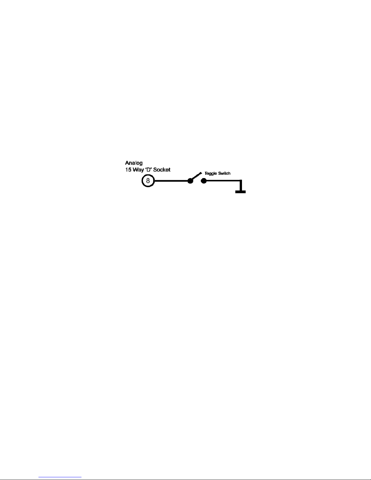
Peak Input
The peak input is a control signal and has two main purposes. It controls what data gets
applied to the torque analog output and it can be used to reset the peaks.
The peak input is activated by grounding pin 8 of the Analog 15 Way ‘D’ Socket. The best way
to control the peak input is to use a toggle switch.
Analog Output
When activated any analog output channel configured as “Torque – Auto Assign” will switch
from being the current torque value to the highest measured torque value since reset, if the
analog output is not unipolar then the torque direction will be output.
Peak Reset
When the peak input is toggled, i.e. off-on-off or on-off-on, all internal peak values on both
analog and digital interfaces will be reset to defaults. A peak input toggle will also clear any
latched fault condition.

Sensor Technology 2016 Page 11 ORT4076IM (Rev 1)
Analog Outputs
The transducer has two analog outputs which can be configured to different data values,
voltages, currents and scales.
Basic models are preconfigured based on model and options selected, advanced models are
user selectable. The configuration of the analog outputs for advanced models is done using
Transducer Control; please refer to the Transducer Control manual for further details.
The following tables show the default assignments for each model and analog option.
Data Assignments
Model Analog CH0 (Torque) Analog CH1 (Speed)
ORT230
RWT410
RWT430
Torque – Auto Assign
1
Scale: 0 – FSD
Torque – Peak
Scale: 0 – FSD
ORT231
ORT232
RWT411
RWT412
RWT431
RWT432
Torque – Auto Assign
1
Scale: 0 – FSD
Speed Fast (RPM)
Scale: 0 – Max Speed
ORT233
RWT413
RWT433
Torque – Auto Assign
1
Scale: 0 – FSD
Power (Watts)
Scale: 0 – ((FSD x Max Speed) / 9.551)
ORT240
RWT420
RWT440
Advanced Model - User Selectable
Factory Default:
Torque – Auto Assign
1
Scale: 0 – FSD
Advanced Model - User Selectable
Factory Default:
Torque – Peak
Scale: 0 – FSD
ORT241
ORT242
RWT421
RWT422
RWT441
RWT442
Advanced Model - User Selectable
Factory Default:
Torque – Auto Assign
1
Scale: 0 – FSD
Advanced Model - User Selectable
Factory Default:
Speed Fast (RPM)
Scale: 0 – Max Speed
1
The value output by channels assigned with Torque – Auto Assign is dependent on the peak
switch. If unconnected or if Peak is OFF the channel is assigned with Torque, if Peak is ON
the channel is assigned with Torque – Peak. Refer to the Peak Input section for more details.
Sensor Technology 2016 Page 12 ORT4076IM (Rev 1)
Voltage/Current Assignments
Assignments apply to both channels.
Option Analog Output Type Analog Output
OPTN-A
ORT23x/RWT41x/RWT43x
Voltage Bipolar ±1V, 0V Zero
OPTN-B
ORT23x/RWT41x/RWT43x
Voltage Bipolar ±5V, 0V Zero
OPTN-C
ORT23x/RWT41x/RWT43x
Voltage Bipolar ±10V, 0V Zero
OPTN-D
ORT23x/RWT41x/RWT43x
Current 0 - 20mA
OPTN-E
ORT23x/RWT41x/RWT43x
Current 4 - 20mA
OPTN-U
ORT23x/RWT41x/RWT43x
Voltage
User specified when ordered
check transducer label
OPTN-V
ORT23x/RWT41x/RWT43x
Current ±8mA, 12mA Zero
Advanced Model
ORT24x/RWT42x/RWT44x
Voltage
User Selectable
Factory Default:
Bipolar ±10V, 0V Zero
Advanced Model (OPTN-F)
ORT24x/RWT42x/RWT44x
User Selectable
Voltage/Current
User Selectable
Factory Default:
Bipolar ±10V, 0V Zero
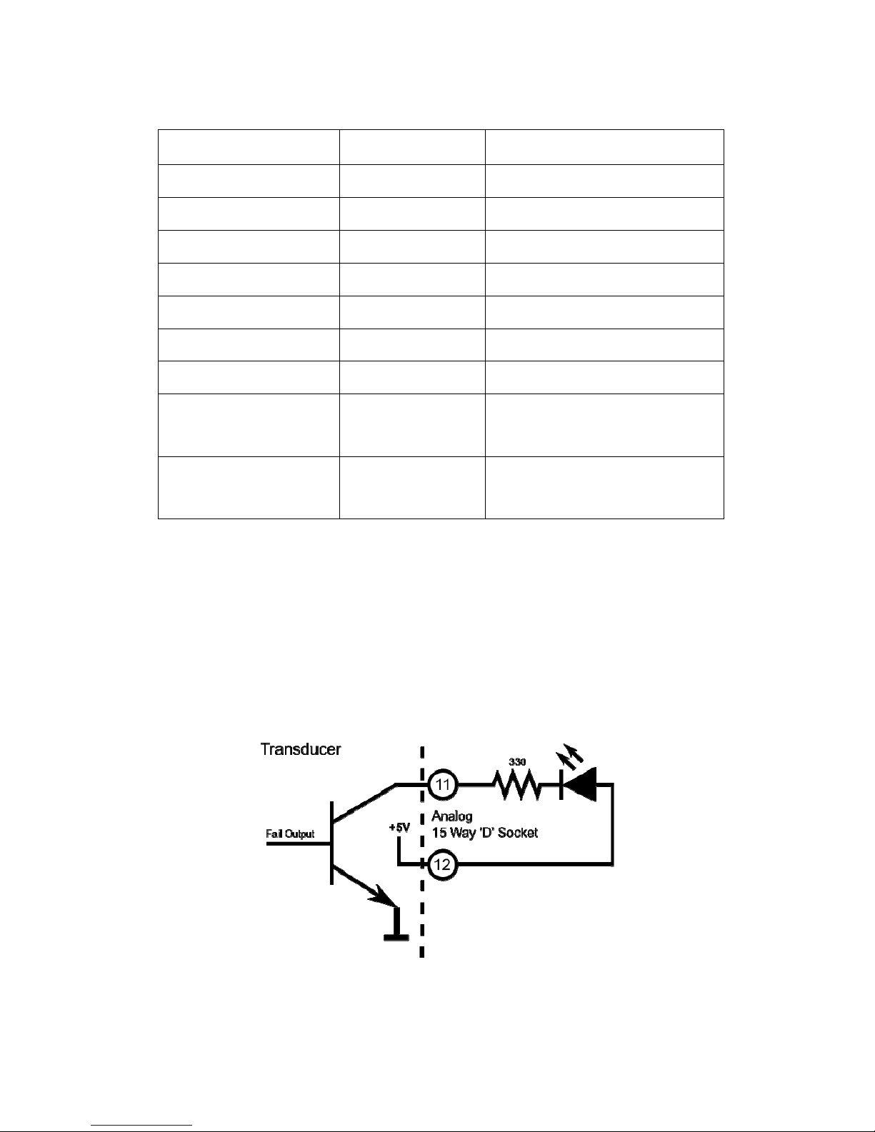
Fail Output
The fail output signals when an error or fault condition occurs within the transducer. The fail
output is linked to the internal transducer error flag. Any error condition detected will switch
the output on and will remain on until the error clears. This behaviour is different from the LED
which latches.
The best use of the fail output is as a safety shutdown signal.
The fail signal is an open collector output. The circuit diagram below shows an example of
how to wire an LED to the output.
In firmware prior to version 5 the fail output is shared with the limits module. If the limits
module is active the fail output is overridden.

Sensor Technology 2016 Page 13 ORT4076IM (Rev 1)
Limit Output
The limit output is driven by the limits module. The limits module is a configurable set of
parameters which switch the limit output on or off when certain conditions are met. These
conditions include triggering when torque or speed goes above or below a set level, as well
as more advanced processes like auto reset or triggering after a delay
The limits module is configured using Transducer Control; please refer to the Transducer
Control manual for further details.
The limit signal is an open collector output. The circuit diagram below shows an example of
how to wire an LED to the output.
In firmware prior to version 5 the limits module does not have a dedicated output pin, instead
the limit output is routed to the Fail Output pin (11). When the limits module is active the fail
out signal is overridden.
Sensor Technology 2016 Page 14 ORT4076IM (Rev 1)
Zeroing the transducer
Zeroing the transducer has the effect of introducing an offset to the torque reading. The zero
can be used to remove any offset that may have been introduced from its mechanical
installation or from idle torque present. It must be stressed that the zero offset is no substitute
for correct installation.
When using high zero offsets, care must be taken not to overstrain the transducer. A zero
offset will not extend the full scale rating of the transducer, e.g. if a transducer was zeroed at
50% then a further 50% was applied, the transducer will have reached full scale, even though
the transducer would be reading of 50%. A zero offset of 10% or greater will trigger a warning
condition and will be indicated by a warning LED sequence.
The transducer can be zeroed by using either a digital command or an electrical signal.
There are 3 zero modes that can be used:
Normal Zero: Sets the zero offset to the current torque reading.
Average Zero: Sets the zero offset to the average of 8 consecutive torque readings.
Fixed Zero: A fixed value can be input and saved. Fixed Zero is only available via the
Transducer Control Software.
Unless the zero is saved, any zero offset applied will be lost after a power cycle.
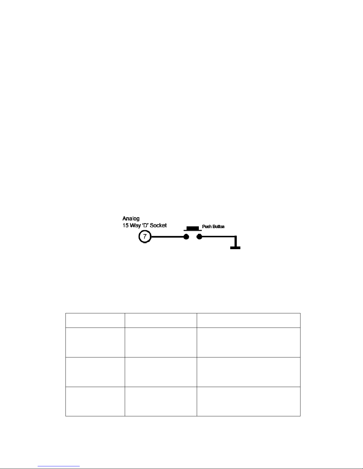
Electrical Signal
Zeroing the transducer electrically can be achieved by grounding the Zero Input on pin 7 of
the Analog 15 Way ‘D’ Socket. The best way of zeroing a transducer is to use a push button.
A simple circuit diagram using a push button is shown below.
The zero action is only carried out once the input has been ungrounded. Grounding the zero
input momentarily (less than 2 seconds) will initiate a normal zero, grounding the input for
longer will initiate other modes. When the zero input is grounded for more than 2 seconds the
LED will start flashing to indicate that a new mode has been selected, subsequent mode
changes are shown by an increase in flash frequency. The LED will not flash if an error
condition is present.
The table below shows the various modes and timings.
Ground Hold Time LED Flash Zero Mode / Action
0 - 2 Seconds None Normal Zero
4 - 6 Seconds 1 Hz Green Flash Average Zero
Greater than
6 Seconds
2 Hz Green Flash
Transducer will save the current zero
offset so that it is remembered across
power cycles.

Sensor Technology 2016 Page 15 ORT4076IM (Rev 1)
Digital Command
There are multiple digital commands to select the different zero modes, refer to the
transducer communication protocol manual.
Our Torqview and Transducer Control software programs implement these commands
providing a simple way of zeroing the transducer.
Resetting transducer to factory default
To reset the transducer to the factory default settings (i.e. the functions set by the factory on
purchase) follow the steps below:
1. Turn off transducer.
2. While holding in the zero button, power the transducer. The LED will stay solid green
until the zero button is released.
3. Allow the transducer to carry out its BIT procedure.
4. When the LED is solid green all user-adjusted parameters will have been reset to the
factory defaults.

Sensor Technology 2016 Page 16 ORT4076IM (Rev 1)
Examples of reading/collecting data
For diagrammatic purposes only the ORT230/240 model is shown.

Sensor Technology 2016 Page 17 ORT4076IM (Rev 1)
Optional Accessories
Analog Lead
The Analog Lead is a 2.5m length - 15 way ‘D’ type connector (female) to 12 pin Lumberg
(female). It can be used for any ORT series transducers.
Digital Lead (ORT240 series ONLY)
The Digital Lead is a 2.5m length - 15 way ‘D’ type connector (male) to 12 pin Lumberg
(male). It is used to configure the ORT240 series.
Digital Adaptor Lead (ORT240 series ONLY)
The Digital Adaptor Lead is an optional accessory and plugs into the 15 way ‘D’ type
connector on the 2.5m Digital Lead to provide a DC jack for power and RS232 and/or a USB
connection, depending upon the options requested. Note: USB specification limits the length
of a cable between host and full speed device to 5 meters. A USB Extender is required for
distances greater than 5m; please consult the factory for USB Extenders.
Additional Related Products and Transducer Resources
Transducer Display ETD
The Transducer Display ETD is a readout suitable for all ORT transducers. Although it is
primarily used to display torque and peak torque, it can also display speed and power,
provide access to the analog outputs from the transducer and connect the transducer to a PC
for use with TorqView and Transducer Control.
Transducer Signal Breakout Unit (SBU)
The Transducer Signal Breakout Unit, which when plugged in powers the transducer and
keeps all of the inputs and outputs in one place. The Transducer Signal Breakout Unit
provides 4mm sockets to output an analog torque and speed signal. It enables switching
between DC Volts, 0-20mA, 4-20mA, zero torque, angle and enable peak hold. The
Transducer Signal Breakout Unit also allows communication with a PC via the built-in USB
and RS232 ports. The Transducer Signal Breakout Unit is powered by a supply voltage of
12-32VDC with a minimum current of 1 amp (to supply peak start-up current).
AC Mains Adaptor Power Supply (PSU)
A AC Mains Adaptor Power supply is required to provide 12-32VDC to the ORT series
Transducer and Transducer Signal Breakout Unit.
TorqView (ORT240 series ONLY)
TorqView is an easy to use graphical front end Virtual Instrumentation Display PC Interface
Software program for use with the ORT240 series transducers. It allows the Torque, Speed,
Power and Temperature values to be displayed in charts, dials and digital bars and can be
used to assist data recording. For further information on TorqView please refer to the
TorqView User Manual.
Transducer Control Program (ORT240 series ONLY)
Transducer Control is an all-round application to unlock the advanced functionality of the
ORT240 Series Transducer. Transducer Control enables the user to exploit the flexibility of
the advanced transducer series by configuring the run time parameters of the transducer to
best suit their application.
Transducer Communication Protocol (ORT240 series ONLY)
The Transducer Communication Protocol describes the protocol required to communicate
with a transducer on either RS232 or USB. The Transducer uses a simple request and send
protocol, which defines the commands for requesting data and configuring functionality.
Further information on the Transducer Communication Protocol is available from the factory
or as a download from our website: www.sensors.co.uk/documents
Transducer DLL Programmers Guide (ORT240 series ONLY)
The Transducer DLL Programmers Guide provides information on how a transducer can be
integrated into a third party software program. The DLL simplifies the use of the USB and
RS232 interfaces by providing a unified interface to access transducers connected via either
method; it takes care of the low-level driver access, protocol negotiation and data
manipulation. Further information on the Transducer DLL Programmers Guide is available
from the factory or as a download from our website: www.sensors.co.uk/documents

Sensor Technology 2016 Page 18 ORT4076IM (Rev 1)
Leads
Analog Lead - Pin Out
2.5m length - 15 way ‘D’ type connector (female) to 12 pin Lumberg (female)
15way ‘D’ type connector (Pwr&Out) 12 Pin male on transducer
Pin Description Pin
1 12-32VDC input G
2 GND M
3 Analog GND J
4 Analog CH1 / Speed (V or I) E
5 Analog CH0 / Torque (V or I) C
6 Reserved K
7 Zero Input (low = zero) A
8 Peak Input (low = peak) B
9 Reserved F
10 Limit Output D
11 Fail Output L
12 GND H
Female 15 way ‘D’
Female 12 way
Lumberg
Do NOT supply any
voltage to these ports.
Closure to
g
round onl
y

Sensor Technology 2016 Page 19 ORT4076IM (Rev 1)
Digital Lead - Pin Out (ORT240 Series ONLY)
2.5m length - 15 way ‘D’ type connector (male) to 12 pin Lumberg (male)
15 way ‘D’ type connector (Pwr&Out) 12 Pin female on transducer
Pin Description Pin
1 12-32 VDC Input G
2 GND E
3 RS232 RXD / CAN LO A
4 GND
5 RS232 TXD / CAN HI K
6 GND
7 USB + C
8 USB - L
9 USB 0V D
10 USB Power B
11 Fail Output H
12 +5V OUT F
13 Zero Angle J
14 RPM M
Male 15 way ‘D’
Male 12 way
Lumberg
DIN45321 0332 12

Sensor Technology 2016 Page 20 ORT4076IM (Rev 1)
Transducer Connections
Analog
Digital
Do NOT supply any
voltage to these ports.
Closure to
g
round onl
y
 Loading...