


ORT230/240 SERIES
TRANSDUCER
USER MANUAL
CAUTION
This instruction manual should be read carefully and the
safety instructions observed before installing or operating
the equipment related to this manual.
Apollo Park, Ironstone Lane, Wroxton, Banbury
Oxon, OX15 6AY
Tel: +44 (0)1869 238400 Fax: +44 (0)1869 238401
Email: info@sensors.co.uk Web: www.sensors.co.uk

Sensor Technology 2016 Page 1 ORT4076IM (Rev 1)
While every precaution has been exercised in the compilation of this document to ensure the
accuracy of its contents, Sensor Technology Ltd, assumes no responsibility for any errors or
omissions. Additionally, no liability is assumed for any damages that may result from the use
of the information contained in this document.
Copyright
Copyright 2016 Sensor Technology Ltd. All rights Reserved.
Copying or reproducing of all or any part of the contents of this manual is strictly prohibited
without the express permission of Sensor Technology.
Trademarks
TorqSense is a registered trademark of Sensor Technology Ltd.
TorqView is a trademark of Sensor Technology Ltd.
LabVIEW is a trademark of National Instruments Corporation.
National Instruments is a trademark of National Instruments Corporation.
Windows is a registered trademark of Microsoft Corporation.
Lifetime Warranty
Sensor Technology Ltd’s standard range of products are warranted against manufacturing
defects and component failure for two years from date of purchase, subject to fair wear and
tear and return for the first year's free of charge annual re-calibration. This warranty is
extended indefinitely if the equipment is returned to Sensor Technology, or its distributor, for
annual re-calibration, when software and hardware updates, if required, will be carried out
free of charge. Standard range means those products as described in the company's product
data sheets.

Sensor Technology 2016 Page 2 ORT4076IM (Rev 1)
Table of Contents
Getting Started......................................................................................................................... 3
Introduction............................................................................................................................ 3
Unpacking the transducer ..................................................................................................... 3
Mechanical Installation .......................................................................................................... 4
Operating Principles .............................................................................................................. 5
Operation.................................................................................................................................. 6
Powering the transducer ....................................................................................................... 6
Using the transducer ............................................................................................................. 6
Built In Test (BIT) .................................................................................................................. 7
Normal Operation .................................................................................................................. 8
Peak Mode........................................................................................................................ 8
Analog Scaling..................................................................................................................8
Warning Signals .................................................................................................................... 9
Error Signals........................................................................................................................ 10
Peak Input ........................................................................................................................... 10
Analog Output.................................................................................................................10
Peak Reset .....................................................................................................................10
Analog Outputs.................................................................................................................... 11
Data Assignments........................................................................................................... 11
Voltage/Current Assignments......................................................................................... 12
Fail Output........................................................................................................................... 12
Limit Output ......................................................................................................................... 13
Zeroing the transducer ........................................................................................................ 14
Electrical Signal .............................................................................................................. 14
Digital Command ............................................................................................................ 15
Resetting transducer to factory default ............................................................................... 15
Examples of reading/collecting data ................................................................................... 16
Optional Accessories............................................................................................................ 17
Analog Lead ........................................................................................................................ 17
Digital Lead (ORT240
series ONLY)...................................................................................
17
Digital Adaptor Lead (ORT240 series ONLY) ..................................................................... 17
Additional Related Products and Transducer Resources................................................. 17
Transducer Display ETD ..................................................................................................... 17
Transducer Signal Breakout Unit ........................................................................................ 17
AC Mains Adaptor Power Supply........................................................................................ 17
TorqView (ORT240 series ONLY)....................................................................................... 17
Transducer Control Program (ORT240 series ONLY) ........................................................ 17
Transducer Communication Protocol (ORT240 series ONLY) ........................................... 17
Transducer DLL Programmers Guide (ORT240 series ONLY) .......................................... 17
Leads ...................................................................................................................................... 18
Analog Lead - Pin Out......................................................................................................... 18
Digital Lead - Pin Out (ORT240 Series ONLY)................................................................... 19
Transducer Connections ...................................................................................................... 20
Analog ................................................................................................................................. 20
Digital .................................................................................................................................. 20
Data Specification . . . . . . . Attached
Appendices (ORT240 series ONLY)
1. ORT240 Series Transducer Control Utility
Attachments (the following documents may also be attached)
1. TorqView User Guide

Sensor Technology 2016 Page 3 ORT4076IM (Rev 1)
Getting Started
Introduction
The Optical Rotary Torque Transducer provides a method of precisely
measuring bi-directional rotary or static torque. It can also be fitted with a speed sensor for
monitoring in dynamic applications, enabling direct measurements of transmitted power.
The ORT series transducers require no external instrumentation and has its own built in test
capability. Its compact size makes it ideal for use in applications where there is little space for
any extra equipment. Analog voltage outputs are standard, with current outputs available as
an option. The ORT240 series can also be connected to a PC via USB (optional) or RS232
so that its configuration can be changed, or by using TorqView to display torque, speed and
power.
Unpacking the transducer
The following standard components are included:
▪ 1 x ORT Series Transducer
▪ 1 x ORT Electronics Module
▪ 1 x User Manual
▪ 1 x Calibration Certificate
Additional components for ORT240 series:
▪ 1 x TorqView program installation USB flash drive, ORT Configuration Software,
Manuals & Appendices in PDF format, USB driver.
The following items may also be included:
▪ 12pin Lumberg (female) and/or 12pin Lumberg (male).
▪ 1 x 2.5m Analog Lead - 15 way ‘D’ type connector (female) to 12pin Lumberg
(female).
▪ 1 x 2.5m Digital Lead - 15 way ‘D’ type connector (male) to 12pin Lumberg (male).
(ORT240 series transducer ONLY).
▪ 1 x Digital Adaptor Lead (DC Jack with USB and/or RS232 connections, depending
on options requested) (ORT240 series transducer ONLY).
▪ 1 x Transducer Display ETD
▪ 1 x AC Mains Adaptor Power Supply.
▪ 1 x Transducer Signal Breakout Unit.
▪ 1 x Analog Dongle.
CAUTION
The ORT series transducers should not be operated at any torque load greater or
speed faster than that specified in the Product data sheet and on the Transducer.
CAUTION
The ORT series transducers should be installed using correct couplings rated for
the maximum torque and speed for the operation.
CAUTION
The ORT series transducers should not be operated in an environment where that
operation could be life threatening or a danger to personnel.
CAUTION
In electrically noisy environments, the ORT series transducers should be earthed
using the earthing post located on the transducer.

Sensor Technology 2016 Page 4 ORT4076IM (Rev 1)
Mechanical Installation
To obtain the best measurements from your torque transducer it is essential that it is
correctly installed.
To avoid damaging the transducer during the installation process it is highly recommended
that it is electrically connected and working so that any torque overloads applied due to
handling can be monitored.
For Transducers above 1Nm or 10lbf.in. it is recommended that the body of the
transducer is restrained from rotation using a strap or straps connected to the tapped holes
in the end plates and that it is not rigidly mounted. Couplings should be used to allow for
angular misalignment while the transducer shaft takes up any parallel misalignment. Care
should be taken not to induce any end loads or bending moments to the shaft, see below,
as these may induce inaccuracies to the torque measurement and in extreme cases
damage the transducer.
Should rapid variations in torque need to be measured in detail e.g.
torque fluctuations in gearboxes or multi vane pumps then it is
recommended using torsionally rigid couplings fitted at both ends of
the transducer shaft such as single membrane couplings and that
these are correctly selected for the transducer rating and speed.
An undersized coupling will not transmit the torque while the high
inertia of an oversized coupling can result in instantaneous peak
torques far in excess of the measured torque. Alternatively, for lower
bandwidth applications where it is more important to measure the
‘average’ torque rather than fast torque fluctuations then couplings
with a degree of compliance would be more appropriate.
Never use a solid coupling to connect a ORT series transducers
Torque Transducer
For Transducers below 1Nm or 10lbf.in or if the application
requires the body to be rigidly mounted then it is recommended that
double couplings should be used at each end to compensate for any
misalignment of the input/output shafts and the system designed to
eliminate any end loads on the transducer shaft. For applications
where end loads cannot be avoided please consult the sales
department for advice prior to ordering.
When using a pulley or pulleys it is recommended a bearing block or
blocks should be used to ensure bending loads are not transmitted to
the transducer.
Lastly, consider using a guard over the transducer and couplings
Single membrane
coupling
(
Flexible mountin
g)
Double membrane
coupling
(Rigid mounting)

Sensor Technology 2016 Page 5 ORT4076IM (Rev 1)
Whilst the transducer is resistant to EMC interference to BS EN 61326-1:2006, the
sensible routing of cables is important to avoid possible EMC interference. Avoid
running the transducer cables close, and/or parallel, to high voltage cables, solenoid
valves, generators or inverters etc. If the cables must follow the same route as
interfering cables then additional screening such as metal conduit should be used to
provide isolation.
To avoid damaging the transducer during installation it is highly recommended that
it is electrically connected and working during this process so that any torque
overloads due to handling can be monitored.
Operating Principles
The shaft of the transducer should be connected to the mechanical system on which the
measurements are to be made using appropriate couplings so it can rotate freely up to its
maximum recommended speed, with relation to the transducers body and bearings fitted.
The technology for our Optical ORT230/240 Series Torque Transducers is based on an
extensively proven and developed measurement principle whereby two discs with segmented
gratings are positioned on the shaft so that the opaque sectors on one disc partially obscure
the clear sectors on the other. Light passes through the sectors and is detected by
photovoltaic detectors. The intensity of light beams, which is constantly monitored, is
modulated by the applied torque and produces an electrical output that is used to provide a
precise indication of the torque transmitted by the shaft. The light intensity is automatically
controlled within the transducer body by a monitor cell. Lamps used to provide the light
source are selected to ensure they have a long life and high stability.
The ORT series transducers can sense both polarity output signals. Torque applied in the
clockwise sense along the transducer shaft axis produces a positive polarity output signal
while torque applied in the anticlockwise sense produces a negative polarity output signal.
If an optical rotary speed sensor is fitted, a light beam is interrupted by the rotation of a disc
consisting of alternate opaque and translucent segments attached to the shaft. Both 60 line
and 360 line encoders are available.
The thermal characteristics of the steel shaft are compensated by having an internal
temperature sensor monitoring the shaft temperature at all times. This information is then
used to correct the modulus of the steel.
Pre-load, note:
All ORT230/240 transducers with a LED on the separate electronics module have a bearing
pre-load spring fitted internally at the left hand
side (pre-load end) of the transducer head
when viewing the label of the transducer head and the connector and gland facing towards
you.
If there is a possibility of an end load being applied to the transducer, the transducer
should be orientated during installation such that the load is applied at the pre-load
end (side with the internally fitted spring). Excessive end loads must be avoided and it
is recommended that appropriate couplings be used to compensate for axial and radial
misalignment.

Sensor Technology 2016 Page 6 ORT4076IM (Rev 1)
Operation
Powering the transducer
To power the transducer a supply voltage of 12-32VDC is required with a minimum current of
1 amp (to supply peak start-up current). If a Transducer Display ETD is used the ETD will
provide power for the transducer. If a Transducer Signal Breakout Unit is used the power
supply should be plugged into the DC jack on the box. If a Digital Adaptor Lead is used the
power supply should be plugged into the DC jack on the lead.
If a Transducer Display ETD, Transducer Signal Breakout Unit or a Digital Adaptor Lead is
not used, then the power supply can be provided by using either the 2.5m Analog or Digital
Lead’s 15 way ‘D’ type connector with a supply voltage of 12-32VDC on Pin 1 and Ground on
Pin 2.
Note: It is imperative that the voltage does not drop below 12V at any stage.
Using the transducer
1. Switch on the ORT series transducer by ensuring power is supplied.
2. Allow the transducer to carry out its Built In Test (BIT) procedure. Refer to the Built In
Test section for further details.
3. Allow five minutes for the equipment to reach thermal equilibrium before making any
measurements.
4. Zero the transducer, refer to the Zeroing the transducer section.
5. The transducer is ready for use, examples of different ways to extract data can be
found in the Examples of reading/collecting data section.
CAUTION
Only provide power through either the Analog or Digital lead.
Do NOT provide power through both leads simultaneously.

Sensor Technology 2016 Page 7 ORT4076IM (Rev 1)
Built In Test (BIT)
When the ORT series transducer is switched on it will carry out its Built In Test (BIT)
procedure. While the BIT procedure is taking place there will be a series of green flashes
from the LED, this is followed by a steady green or an intermittent green flash depending
upon the mode of operation.
If the transducer fails its BIT procedure the transducer will display an error sequence
identifying the results of each system test. The sequence will repeat until the transducer is
powered off.
The error sequence is prefixed with quick succession of red flashes, identifying the LED
sequence as an error condition
After a brief pause a sequence of green and red flashes will indicate the results of each
system test. The following table lists the tests and their test order, for each test the transducer
will output either a GREEN for PASS or RED for FAIL.
Test/Sequence Number System Checks
1
Firmware Version 3/4: Head Connected Check
Firmware Version 5: Electronics Check
2 Not Applicable
3 Temperature Sensor Check
4 Internal Voltage Check
5 Data Configuration Check
6 Calibration Check
7 Not Applicable
8 ORT Parameters Check
If a failure condition exists try power cycling the transducer. Contact the factory if the problem
continues.
If an error occurs during operation (solid RED LED) and is not present on power on, the BIT
procedure may not identify the fault. If the Zero Input has been wired it is possible to display
the Built In Test output, to do this switch the Zero Input ON until the transducer starts flashing
RED.

Sensor Technology 2016 Page 8 ORT4076IM (Rev 1)
Normal Operation
A solid green LED indicates normal mode and the transducer is working correctly.
An intermittent green flash indicates a special mode of operation; the LED sequences below
show the different modes.
Peak Mode
Peak Mode is active, if configured to do so the analog output will output a peak value. Please
refer to the Peak Input section for further details.
Analog Scaling
The Analog Scaling status message is shown when a user defined data or voltage scale has
been applied to either analog channel. This message is only relevant on ORT240 series
transducers.
Peak Mode
Peak Mode and Analog Scaling
[ORT240 Series ONLY]
Analog Scaling
[ORT240 Series ONLY]

Sensor Technology 2016 Page 9 ORT4076IM (Rev 1)
Warning Signals
A warning signal is indicated when the transducer detects a condition which impedes normal
operation or the transducer is operating outside of normal operating parameters.
A warning LED sequence is prefixed with a quick succession of alternating red/green flashes,
identifying the LED sequence as a warning condition. A warning sequence will override the
normal operation mode LED.
After a pause a sequence of green or red flashes will indicate which warning conditions are
flagged. The LED sequence will run through each of the flags in the table below flashing the
LED for each. A RED flash indicates that a condition has been flagged; a GREEN flash
indicates that a condition is clear.
Once the LED sequence is complete the sequence will restart, this will continue until the
warning has cleared.
Sequence
Number
Warning Flag Reason and Action required
1
Analog Fault CH0
(Analog Torque)
In voltage output mode the analog pin is short circuit, in
current output mode the analog output pin is open
circuit. Check the analog connector wiring for Analog
CH0.
2
Analog Fault CH1
(Analog Speed)
In voltage output mode the analog pin is short circuit, in
current output mode the analog output pin is open
circuit. Check the analog connector wiring for Analog
CH1.
3 Zero Offset High
A torque offset greater than 10% of FSD has been
applied to the measured torque value. The offset is set
when the transducer is zeroed, either by the zero input
on the analog connector or via a digital command.
4 Exceeded Temp
Shaft temperature has exceeded normal operating
conditions. Temperature compensation may no longer
be effective or calibration valid.
5 Over Torque Torque greater than the FSD has been applied.
6 Critical Over Torque
Torque greater than 120% of the FSD has been
applied. Contact the factory if the warning continues.
7 Head Disconnect
The transducer head has been disconnected. Power off
the transducer electronics and check the cabling. This
warning is only relevant for transducers with separate
heads/electronics
For example, the following sequence would indicate warnings for ‘Analog Fault CH0’ and
‘Zero Offset High‘:
Sensor Technology 2016 Page 10 ORT4076IM (Rev 1)
Error Signals
An error or fault signal is indicated when the transducer detects a condition which effects its
fundamental operation. An error or fault condition will be indicated by a solid red LED. Any
error that occurs will latch the LED on and it will remain on until the transducer is reset. An
error condition will override a warning and normal mode LED sequence.
If the error persists across multiple power cycles, a fault may have developed with the
transducer and you will need to contact the factory.
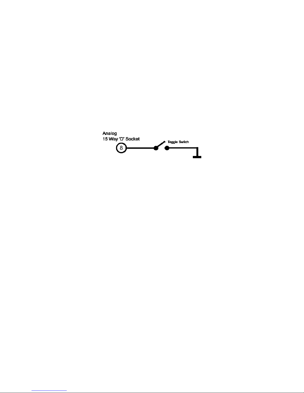
Peak Input
The peak input is a control signal and has two main purposes. It controls what data gets
applied to the torque analog output and it can be used to reset the peaks.
The peak input is activated by grounding pin 8 of the Analog 15 Way ‘D’ Socket. The best way
to control the peak input is to use a toggle switch.
Analog Output
When activated any analog output channel configured as “Torque – Auto Assign” will switch
from being the current torque value to the highest measured torque value since reset, if the
analog output is not unipolar then the torque direction will be output.
Peak Reset
When the peak input is toggled, i.e. off-on-off or on-off-on, all internal peak values on both
analog and digital interfaces will be reset to defaults. A peak input toggle will also clear any
latched fault condition.

Sensor Technology 2016 Page 11 ORT4076IM (Rev 1)
Analog Outputs
The transducer has two analog outputs which can be configured to different data values,
voltages, currents and scales.
Basic models are preconfigured based on model and options selected, advanced models are
user selectable. The configuration of the analog outputs for advanced models is done using
Transducer Control; please refer to the Transducer Control manual for further details.
The following tables show the default assignments for each model and analog option.
Data Assignments
Model Analog CH0 (Torque) Analog CH1 (Speed)
ORT230
RWT410
RWT430
Torque – Auto Assign
1
Scale: 0 – FSD
Torque – Peak
Scale: 0 – FSD
ORT231
ORT232
RWT411
RWT412
RWT431
RWT432
Torque – Auto Assign
1
Scale: 0 – FSD
Speed Fast (RPM)
Scale: 0 – Max Speed
ORT233
RWT413
RWT433
Torque – Auto Assign
1
Scale: 0 – FSD
Power (Watts)
Scale: 0 – ((FSD x Max Speed) / 9.551)
ORT240
RWT420
RWT440
Advanced Model - User Selectable
Factory Default:
Torque – Auto Assign
1
Scale: 0 – FSD
Advanced Model - User Selectable
Factory Default:
Torque – Peak
Scale: 0 – FSD
ORT241
ORT242
RWT421
RWT422
RWT441
RWT442
Advanced Model - User Selectable
Factory Default:
Torque – Auto Assign
1
Scale: 0 – FSD
Advanced Model - User Selectable
Factory Default:
Speed Fast (RPM)
Scale: 0 – Max Speed
1
The value output by channels assigned with Torque – Auto Assign is dependent on the peak
switch. If unconnected or if Peak is OFF the channel is assigned with Torque, if Peak is ON
the channel is assigned with Torque – Peak. Refer to the Peak Input section for more details.
Sensor Technology 2016 Page 12 ORT4076IM (Rev 1)
Voltage/Current Assignments
Assignments apply to both channels.
Option Analog Output Type Analog Output
OPTN-A
ORT23x/RWT41x/RWT43x
Voltage Bipolar ±1V, 0V Zero
OPTN-B
ORT23x/RWT41x/RWT43x
Voltage Bipolar ±5V, 0V Zero
OPTN-C
ORT23x/RWT41x/RWT43x
Voltage Bipolar ±10V, 0V Zero
OPTN-D
ORT23x/RWT41x/RWT43x
Current 0 - 20mA
OPTN-E
ORT23x/RWT41x/RWT43x
Current 4 - 20mA
OPTN-U
ORT23x/RWT41x/RWT43x
Voltage
User specified when ordered
check transducer label
OPTN-V
ORT23x/RWT41x/RWT43x
Current ±8mA, 12mA Zero
Advanced Model
ORT24x/RWT42x/RWT44x
Voltage
User Selectable
Factory Default:
Bipolar ±10V, 0V Zero
Advanced Model (OPTN-F)
ORT24x/RWT42x/RWT44x
User Selectable
Voltage/Current
User Selectable
Factory Default:
Bipolar ±10V, 0V Zero
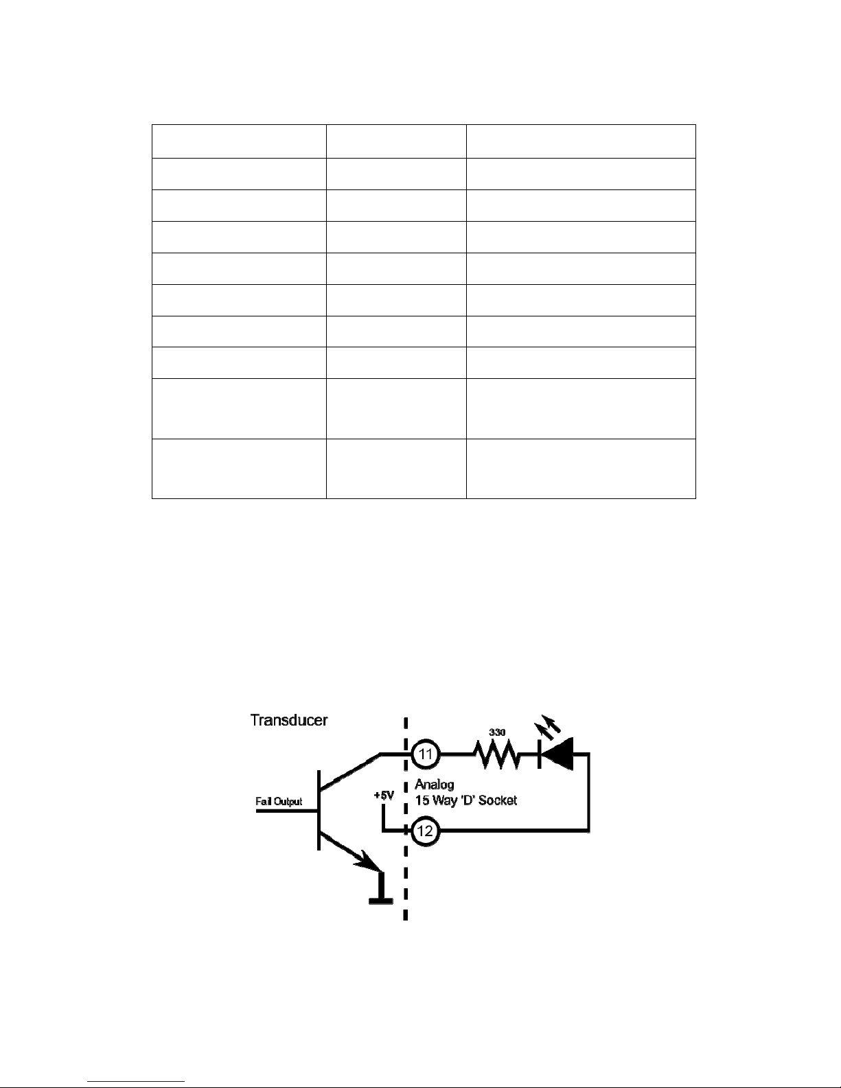
Fail Output
The fail output signals when an error or fault condition occurs within the transducer. The fail
output is linked to the internal transducer error flag. Any error condition detected will switch
the output on and will remain on until the error clears. This behaviour is different from the LED
which latches.
The best use of the fail output is as a safety shutdown signal.
The fail signal is an open collector output. The circuit diagram below shows an example of
how to wire an LED to the output.
In firmware prior to version 5 the fail output is shared with the limits module. If the limits
module is active the fail output is overridden.

Sensor Technology 2016 Page 13 ORT4076IM (Rev 1)
Limit Output
The limit output is driven by the limits module. The limits module is a configurable set of
parameters which switch the limit output on or off when certain conditions are met. These
conditions include triggering when torque or speed goes above or below a set level, as well
as more advanced processes like auto reset or triggering after a delay
The limits module is configured using Transducer Control; please refer to the Transducer
Control manual for further details.
The limit signal is an open collector output. The circuit diagram below shows an example of
how to wire an LED to the output.
In firmware prior to version 5 the limits module does not have a dedicated output pin, instead
the limit output is routed to the Fail Output pin (11). When the limits module is active the fail
out signal is overridden.
Sensor Technology 2016 Page 14 ORT4076IM (Rev 1)
Zeroing the transducer
Zeroing the transducer has the effect of introducing an offset to the torque reading. The zero
can be used to remove any offset that may have been introduced from its mechanical
installation or from idle torque present. It must be stressed that the zero offset is no substitute
for correct installation.
When using high zero offsets, care must be taken not to overstrain the transducer. A zero
offset will not extend the full scale rating of the transducer, e.g. if a transducer was zeroed at
50% then a further 50% was applied, the transducer will have reached full scale, even though
the transducer would be reading of 50%. A zero offset of 10% or greater will trigger a warning
condition and will be indicated by a warning LED sequence.
The transducer can be zeroed by using either a digital command or an electrical signal.
There are 3 zero modes that can be used:
Normal Zero: Sets the zero offset to the current torque reading.
Average Zero: Sets the zero offset to the average of 8 consecutive torque readings.
Fixed Zero: A fixed value can be input and saved. Fixed Zero is only available via the
Transducer Control Software.
Unless the zero is saved, any zero offset applied will be lost after a power cycle.
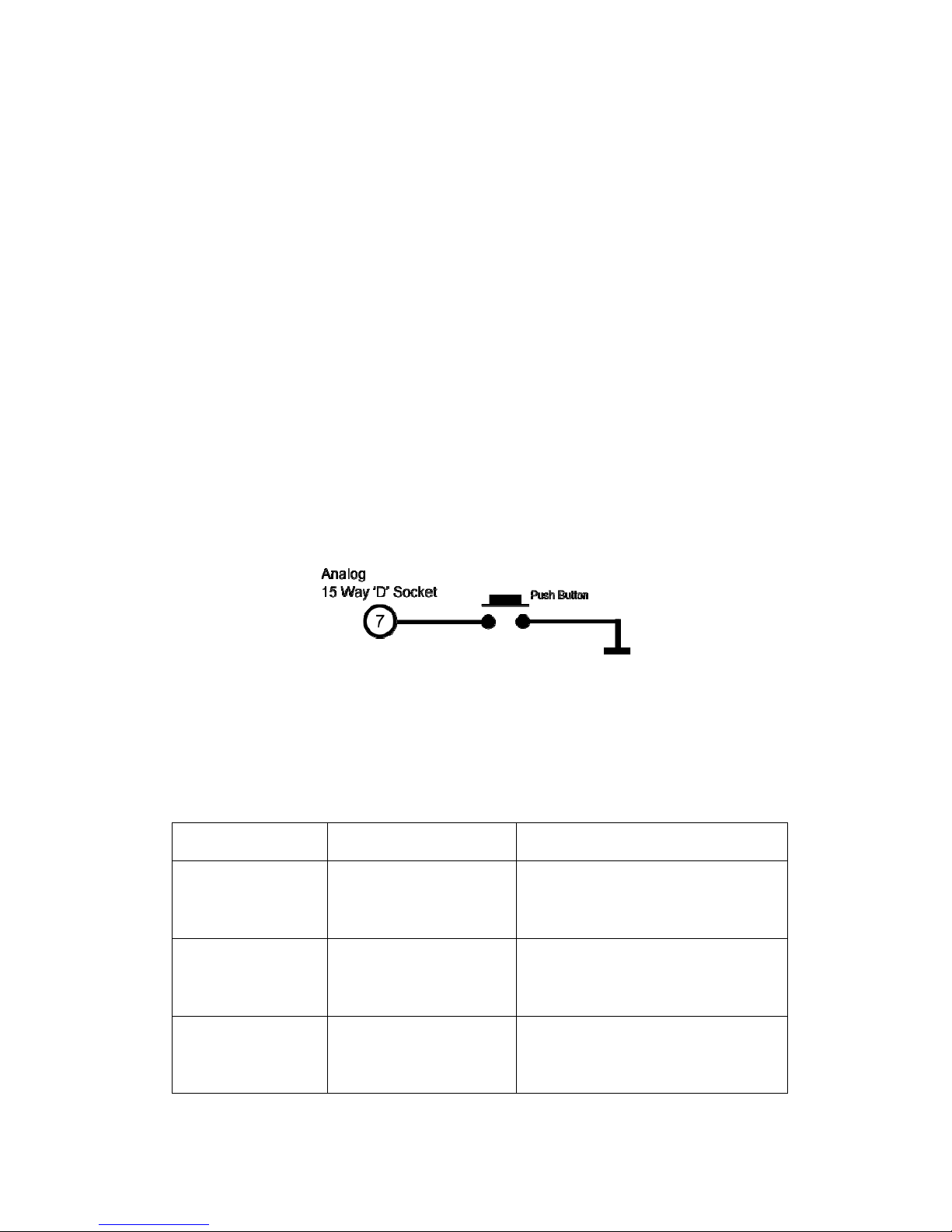
Electrical Signal
Zeroing the transducer electrically can be achieved by grounding the Zero Input on pin 7 of
the Analog 15 Way ‘D’ Socket. The best way of zeroing a transducer is to use a push button.
A simple circuit diagram using a push button is shown below.
The zero action is only carried out once the input has been ungrounded. Grounding the zero
input momentarily (less than 2 seconds) will initiate a normal zero, grounding the input for
longer will initiate other modes. When the zero input is grounded for more than 2 seconds the
LED will start flashing to indicate that a new mode has been selected, subsequent mode
changes are shown by an increase in flash frequency. The LED will not flash if an error
condition is present.
The table below shows the various modes and timings.
Ground Hold Time LED Flash Zero Mode / Action
0 - 2 Seconds None Normal Zero
4 - 6 Seconds 1 Hz Green Flash Average Zero
Greater than
6 Seconds
2 Hz Green Flash
Transducer will save the current zero
offset so that it is remembered across
power cycles.

Sensor Technology 2016 Page 15 ORT4076IM (Rev 1)
Digital Command
There are multiple digital commands to select the different zero modes, refer to the
transducer communication protocol manual.
Our Torqview and Transducer Control software programs implement these commands
providing a simple way of zeroing the transducer.
Resetting transducer to factory default
To reset the transducer to the factory default settings (i.e. the functions set by the factory on
purchase) follow the steps below:
1. Turn off transducer.
2. While holding in the zero button, power the transducer. The LED will stay solid green
until the zero button is released.
3. Allow the transducer to carry out its BIT procedure.
4. When the LED is solid green all user-adjusted parameters will have been reset to the
factory defaults.

Sensor Technology 2016 Page 16 ORT4076IM (Rev 1)
Examples of reading/collecting data
For diagrammatic purposes only the ORT230/240 model is shown.

Sensor Technology 2016 Page 17 ORT4076IM (Rev 1)
Optional Accessories
Analog Lead
The Analog Lead is a 2.5m length - 15 way ‘D’ type connector (female) to 12 pin Lumberg
(female). It can be used for any ORT series transducers.
Digital Lead (ORT240 series ONLY)
The Digital Lead is a 2.5m length - 15 way ‘D’ type connector (male) to 12 pin Lumberg
(male). It is used to configure the ORT240 series.
Digital Adaptor Lead (ORT240 series ONLY)
The Digital Adaptor Lead is an optional accessory and plugs into the 15 way ‘D’ type
connector on the 2.5m Digital Lead to provide a DC jack for power and RS232 and/or a USB
connection, depending upon the options requested. Note: USB specification limits the length
of a cable between host and full speed device to 5 meters. A USB Extender is required for
distances greater than 5m; please consult the factory for USB Extenders.
Additional Related Products and Transducer Resources
Transducer Display ETD
The Transducer Display ETD is a readout suitable for all ORT transducers. Although it is
primarily used to display torque and peak torque, it can also display speed and power,
provide access to the analog outputs from the transducer and connect the transducer to a PC
for use with TorqView and Transducer Control.
Transducer Signal Breakout Unit (SBU)
The Transducer Signal Breakout Unit, which when plugged in powers the transducer and
keeps all of the inputs and outputs in one place. The Transducer Signal Breakout Unit
provides 4mm sockets to output an analog torque and speed signal. It enables switching
between DC Volts, 0-20mA, 4-20mA, zero torque, angle and enable peak hold. The
Transducer Signal Breakout Unit also allows communication with a PC via the built-in USB
and RS232 ports. The Transducer Signal Breakout Unit is powered by a supply voltage of
12-32VDC with a minimum current of 1 amp (to supply peak start-up current).
AC Mains Adaptor Power Supply (PSU)
A AC Mains Adaptor Power supply is required to provide 12-32VDC to the ORT series
Transducer and Transducer Signal Breakout Unit.
TorqView (ORT240 series ONLY)
TorqView is an easy to use graphical front end Virtual Instrumentation Display PC Interface
Software program for use with the ORT240 series transducers. It allows the Torque, Speed,
Power and Temperature values to be displayed in charts, dials and digital bars and can be
used to assist data recording. For further information on TorqView please refer to the
TorqView User Manual.
Transducer Control Program (ORT240 series ONLY)
Transducer Control is an all-round application to unlock the advanced functionality of the
ORT240 Series Transducer. Transducer Control enables the user to exploit the flexibility of
the advanced transducer series by configuring the run time parameters of the transducer to
best suit their application.
Transducer Communication Protocol (ORT240 series ONLY)
The Transducer Communication Protocol describes the protocol required to communicate
with a transducer on either RS232 or USB. The Transducer uses a simple request and send
protocol, which defines the commands for requesting data and configuring functionality.
Further information on the Transducer Communication Protocol is available from the factory
or as a download from our website: www.sensors.co.uk/documents
Transducer DLL Programmers Guide (ORT240 series ONLY)
The Transducer DLL Programmers Guide provides information on how a transducer can be
integrated into a third party software program. The DLL simplifies the use of the USB and
RS232 interfaces by providing a unified interface to access transducers connected via either
method; it takes care of the low-level driver access, protocol negotiation and data
manipulation. Further information on the Transducer DLL Programmers Guide is available
from the factory or as a download from our website: www.sensors.co.uk/documents

Sensor Technology 2016 Page 18 ORT4076IM (Rev 1)
Leads
Analog Lead - Pin Out
2.5m length - 15 way ‘D’ type connector (female) to 12 pin Lumberg (female)
15way ‘D’ type connector (Pwr&Out) 12 Pin male on transducer
Pin Description Pin
1 12-32VDC input G
2 GND M
3 Analog GND J
4 Analog CH1 / Speed (V or I) E
5 Analog CH0 / Torque (V or I) C
6 Reserved K
7 Zero Input (low = zero) A
8 Peak Input (low = peak) B
9 Reserved F
10 Limit Output D
11 Fail Output L
12 GND H
Female 15 way ‘D’
Female 12 way
Lumberg
Do NOT supply any
voltage to these ports.
Closure to
g
round onl
y

Sensor Technology 2016 Page 19 ORT4076IM (Rev 1)
Digital Lead - Pin Out (ORT240 Series ONLY)
2.5m length - 15 way ‘D’ type connector (male) to 12 pin Lumberg (male)
15 way ‘D’ type connector (Pwr&Out) 12 Pin female on transducer
Pin Description Pin
1 12-32 VDC Input G
2 GND E
3 RS232 RXD / CAN LO A
4 GND
5 RS232 TXD / CAN HI K
6 GND
7 USB + C
8 USB - L
9 USB 0V D
10 USB Power B
11 Fail Output H
12 +5V OUT F
13 Zero Angle J
14 RPM M
Male 15 way ‘D’
Male 12 way
Lumberg
DIN45321 0332 12

Sensor Technology 2016 Page 20 ORT4076IM (Rev 1)
Transducer Connections
Analog
Digital
Do NOT supply any
voltage to these ports.
Closure to
g
round onl
y

Sensor Technology 2016 Page 21 ORT4076IM (Rev 1)
Declaration of Conformity
EC Directives
We, Sensor Technology Ltd, hereby declare that the products named below, to which this
Declaration of Conformity relates, is in conformity to the requirements of EC Council
Directives and Standards as listed:
2004/108/EC (Electromagnetic compatibility).
BS EN 61326-1:2006, (Electrical equipment for measurement, control and laboratory
use).
Type of Product Rotary Torque Transducer
Product Name(s)
ORT230, ORT231.
ORT240, ORT241.
Intended use:
Measurement of rotary torque within the rated torque
and speed limits as described on the transducer.
……………………….......................................
Managing Director
Sensor Technology Ltd
10
th
November 2016
Apollo Park, Ironstone Lane, Wroxton, Banbury
Oxon, OX15 6AY
Tel: +44 (0)1869 238400 Fax: +44 (0)1869 238401

The ORT 230/240 Transducer offers an ideal means for
precise dynamic measurement of rotary and static torque
less than 100Nm and for bandwidths of up to 50Khz.
The new TorqSense ORT 230/240 torque sensors replace the
E200 ORT series and feature all new electronics that have
produced significant performance gains in resolution, frequency
response, reduced sensor current consumption and faster digital
data throughput.
Low inertia – High Speed capability
because electronics are not fixed
onto shaft
Non contact/brushless
measurement
High Bandwidth
200% safe mechanical
overload
Excellent noise immunity
Separate digital electronics
Operates both statically and dynamically
- clockwise/anti-clockwise
Any full scale torque can be specified within
standard range: 10mNm through to 100Nm
Lifetime warranty
Technology
Benefits
Software
TorqView is an easy to use advanced torque monitoring
software, available to assist data recording and instrumentation
displays that interface with Windows based PCs.
Features include: 3 types of display, text files compatible with
Matlab and Excel and Real time chart plotting.
See TorqView datasheet TSE2099R for more details.
LabView VIs are available for users to design their own process
control applications. DLLs are also available for users to write
their own custom software.
Fixed voltage or current analog outputs (one
for torque and the other for speed or power) for
interfacing with analog instrumentation
BIT Self-diagnostics for letting the manufacturer
know that the transducer’s torque, speed ratings
and calibration due date have not been exceeded.
Simple ‘Sensor status’ output pin
Sensors to monitor shaft temperature for better
compensation and accuracy
Digital outputs, such as RS232, CANbus and USB, for
interfacing with modern instrumentation and laptops
Digital input for configuring transducer via PC
2 x user selectable voltage or current analog
outputs (one for torque and the other for speed,
power or peak torque) for interfacing with analog
instrumentation
Transducer configuration software to allow user
to changes transducer variables
BIT Self-diagnostics for letting users know data
is trustworthy, that the transducer’s torque, speed
ratings and calibration due date have not been
exceeded
Simple ‘Sensor status’ output pin
Sensors to monitor shaft temperature for better
compensation and accuracy
Ability to connect up to 10 transducers using USB
TorqSense ORT 230 series transducers offer:
Whereas, TorqSense ORT 240 series transducers
offer:
Digital ORT 230/240 series Torque Transducer
TORQ
VIEW
Ô
TECHNOLOGY
SENSOR
An extensively developed measurement principle is used, in
which the intensity of light beams is measured by means of
photovoltaic detectors, and the electrical output is used to
provide precise indication of the applied torque transmitted
by the shaft.
The use of this technique results in a transducer being able
to sense torque bi-directionally, have a fast mechanical and
electrical response, low inertia, and complete freedom from
brushes or complex electronics. The absence of brush gear
allows high-speed operation with a continuous rating of up
to 30,000 RPM standard. Further increases in RPM are
available as an option depending upon shaft size.
The torque shaft is of low compliance ½° maximum torsion
deflection on the smaller transducers, and ¼° maximum on
the larger transducers, at full-scale deflection. The lamps
providing the light source are selected to ensure long life and
high stability with the light intensity automatically controlled
within the transducer body by a monitor cell.
© Sensor Technology Ltd 2016 ORT4019R (Preliminary) Feb 2016

Standard
Mechanical Parameters
Cable length
Accuracy
Bandwidth
Safe mechanical overload
Hysteresis
Bearings
1.5metres to interface box
TBC
50Khz
-10ºC to +50ºC
200% of rating
Better than 0.1%
Deep grooved shielded
bearings with oil lubrication
Temperature coefficient
Temperature Range
Less than 0.05% per ºC
Model Dimensions (mm)
ORT230/240 -C,-D,-E
ORT230/240 -F
ORT230/240 -G
ORT230/240 -H
A
75
75
105
130
B
25.4
25.4
38
60
C
1.5
1.5
1.5
1.5
D
62
62
62
62
E
50
50
50
50
F
6.35
6.35
12.7
20
G
56
56
56
56
H
M3
M3
M3
M3
Depth
5
5
6.35
11
J
N/A
19.05
30
53
K
Plain
Flat
3.96
6
L
N/A
0.183
1.98
3.5
Standard Specifications
ORT230/240-C
ORT230/240-D
ORT230/240-E
ORT230/240-F
ORT230/240-G
ORT230/240-H
Torque Range * Maximum Speed Shaft Type
Model Minimum Maximum (RPM)
0 to 10mNm (0 to 1ozf.in)
0 to 25mNm (0 to 3.5ozf.in)
0 to 150mNm (0 to 15ozf.in)
0 to 800mNm (0 to 7lbf.in)
0 to 1.5Nm (0 to 15lbf.in)
0 to 25Nm (0 to 250lbf.in)
30000
30000
30000
30000
20000
15000
Plain
Plain
Plain
Flat
Keyways
Keyways
0 to 20mNm (0 to 3ozf.in)
0 to 100mNm (0 to 10ozf.in)
0 to 750mNm (0 to 100ozf.in)
0 to 1Nm (0 to 10lbf.in)
0 to 20Nm (0 to 200lbf.in)
0 to 100Nm (0 to 1000lbf.in)
* Calibration is possible in any equivalent SI, FPS or MKS units, e.g. gf.cm, lbf.ft, cNm
Transducers may be specified to any torque range between the maximum and minimum for each model.
For example ORT241-C 15mNm, or ORT231-G 10Nm
Data parameters measured at 20ºC
Sensor Technology Ltd reserves the right to change specification and dimensions without notice.
© Sensor Technology Ltd 2016 ORT4019R (Preliminary) Feb 2016

137.60
73.50
22.50
120.00
60.00
8.60
6.80
M3 x 10mm Deep
CABLE GLAND
VIEW ON BASE
56.60
BASE
54.00
Allow for
cable bend
130.60
Allow for
cable bend
20.00
24.00
ORT 230/240 Series Electronics Module
Measurement units: Millimetres (mm)
Data parameters measured at 20ºC
Sensor Technology Ltd reserves the right to change specification and dimensions without notice.
© Sensor Technology Ltd 2016 ORT4019R (Preliminary) Feb 2016

© Sensor Technology Ltd 2016 ORT4019R (Preliminary) Feb 2016
ORT 230/240 Series Torque Transducers - Data Specification
Note 1: Please consult factory for applications requiring rotational speeds that exceed maximum figures given. Transducers fitted for IP65 will have
running speeds considerably reduced, increased drag torque and accuracy can be affected.
Note 2: SM – Static Mode. Dynamic values will depend upon user application and has to be adjusted accordingly.
Note 3: Digital averaging can be configured by user to optimise accuracy/frequency response for specific user applications. Digital averaging default
setting is N=16. For details see User Manual.
Note 4: >5Khz Sample Rate. Up to 10Khz sample rate possible, please consult factory. Digital averaging also affects the analog output, max analog output
3dB Bandwidth = 5Khz when digital average is 1.
Note 5: Output rate figures are calculated from the time taken to capture 10000 torque readings. Testing was conducted with each connection method
configured at its maximum baud rate. The maximum output rate available for CAN and USB is dependant on the transducers setup. USB - USB is a
host based bus architecture, because of this the output rate achievable will be affected by other bus traffic and host activity. USB has two transfer
modes, Single Transfer which requests 1 reading at a time and Bulk Transfer which transfers readings in blocks of 50 Torque/Speed pairs. CAN
Bus - to achieve a Torque reading output rate of 10KHz, the Speed reading output rate must be reduced to 100Hz.
Parameter Condition Data Units
Rotation speed/angle of rotation measurement system
Measurement method Opto switch through slotted disc
Direct output signal Pulse output direct from opto switch (TTL, 5V square wave), output is independent of any analog or digital processing.
Processing Method Update rate for analog and digital outputs
Mode 1 (Slow Method)
Frequency Count
1 Hz
0 RPM 1
< 2000 RPM RPM
Digital Processing
Techniques
Processing modes run
simultaneously and can be
applied to either analog
channel or accessed
individually via a digital
connection.
Mode 2 (Fast Method)
Period Count
> 2000 RPM RPM x ( 1 / ( (RPM - 1) / 2000 + 1 ) )
Hz
Rotational speed (max)
(See Note 1)
30,000 20,000 15,000 RPM
Temperature
Measurement method IR temperature sensor monitoring actual shaft temperature
Temperature accuracy
1
0
C
Reference temperature, TRT 20
0C
Operating range, ΔTO -10 to +50
0
C
Storage range, ΔTS -20 to +70
0
C
Temperature drift (FS) Max 0.05 %FS/0C
Specifications
Combined non-linearity and
hysteresis
TBC %FS
Resolution 0.02 %FS
Repeatability 0.1 %FS
ORT 230 Series Transducers ONLY
Accuracy 200C, SM
(See
Note 2)
TBC %FS
3dB Bandwidth
(See Notes 3&4)
TBC Hz
ORT 240 Series Transducers ONLY
Digital averaging
(See Note 3)
2 4 8 16 32 64 128 N
Accuracy 200C, SM
(See Note 2)
TBC TBC TBC TBC TBC TBC TBC %FS
3dB Bandwidth
(See Note 4)
TBC TBC TBC TBC TBC TBC TBC Hz
Analog output
Output voltages
(Torque/Speed/Power)
Options available: 1 / 5 / 10 / Unipolar (ORT230 Series default setting is 5Vdc)
(ORT240 Series output voltages are user selectable)
Vdc
Load impedance Maximum 1 KΩ
Output currents
(Torque/Speed/Power)
Options available: 4-20 / 0-20 / 128
(ORT240 Series output currents are user selectable)
mA
4-20mA Loop resistance Should not exceed 400 Ω
Digital output (ORT240 Series Transducers ONLY)
Connections CAN Bus RS232 USB
Configuration CAN 2.0B, 11bit Message Identifiers Data Bits: 8, Parity: None, Stop Bits: 1 USB 2.0 Full-Speed
Baud Rate(s) 1 Mbps, 500 Kbps, 250 Kbps, 100 Kbps 115200 bps, 38400 bps, 9600 bps 12 Mbps
Single Transfer Up to 500 Hz
Output Rate
(Note 5)
Up to 10 KHz Up to 1.1 KHz
Bulk Transfer Up to 10 KHz
Power supply
Nominal voltage, VS 12 to 32 (max) V
Current consumption, IS 230 (max) @ 12 VDC mA
Power consumption, WS 3 W
Allowed residual ripple of
supply voltage, V
ripple
500
(above nominal supply voltage)
mVp-p
Electromagnetic compatibility
EMC compatibility EN 61326:2006
Data parameters measured at +20°C
Sensor Technology Ltd reserves the right to change specification and dimensions without notice.

© Sensor Technology Ltd 2016 ORT4019R (Preliminary) Feb 2016
ORT 230/240 Series Torque Transducers - Standard Range
● – Standard feature ◊ – Optional feature
ORT 230/240
Series
Option
Code
Remarks
Torque, Speed, Power Outputs ORT 230 ORT 240
Torque only 230 240
Torque & Speed
(60 pulses/rev)
231
User to specify RPM/FSD
when ordering
Torque & Power
(60 pulses/rev)
233
User to specify Power/FSD
when ordering
Torque & Speed
(60 pulses/rev)
or Power
241
Outputs are user selectable
Standard features
Voltage output ±5v FSD (Fixed) ● B
Voltage outputs from ±1v to ±10v FSD
and unipolar (Variable)
●
Output is user selectable
RS232 output ●
Torque Averaging & Torque Peak ●
Self Diagnostics ● ●
Internal temperature measurement
● ●
Value available on ORT240
series only
Deep grooved shielded bearings with oil
lubrication
● ●
Ingress Protection (IP) 54 ● ●
Link Cable (1.5m)
● ●
From sensor head to
electronics module
Optional features
Keyed Shaft Ends ● ● K
1Nm flats, below 1Nm plain
Plain Shaft Ends ◊ ◊
P
Shaft length may be longer
than keyed end shafts –
consult factory for length.
All sensors below 1Nm will
be plain.
Splined Shaft Ends ◊ ◊ T
Consult factory for details
Voltage output ±1v FSD (Fixed) ◊ A
In place of Option B
Voltage output ±10v FSD (Fixed) ◊ C
In place of Option B
Customer Specified Voltage Output
(Fixed)
◊ U
In place of Option B. User
to specify range/scale when
ordering
Current output 0-20mA (Fixed) ◊
D
In place of Voltage output
options
Current output 4-20mA (Fixed) ◊
E
In place of Voltage output
options
Current output 12±8mA (Fixed)
◊
V
In place of Voltage output
options
Current output 0-20mA, 4-20mA
& 12±8mA (Variable)
◊ F
Current output is user
selectable and in place of
Voltage output. However
user can reselect a Voltage
output, if required. (Note 6)
USB2.0 full speed 12 Mbps Digital output ◊ G
CANbus output ◊ H
In place of RS232
High Speed Bearings
(See Note 7 below)
◊ ◊ J
Sealed Bearings ◊ ◊ S
Ingress Protection (IP) 65 –for sensor
and electronics
(See Note 8 below)
◊ ◊ L
Consult factory for maximum
speed allowance
Link Cable (>1.5m) ◊ ◊ R
Consult factory for length
Note 6: 2 x analog channels available. Default settings are Channel 1 (voltage/current) – torque.
Channel 2 (voltage/current) – speed or power, if ordered.
Note 7: At very high speeds, for better balance the factory recommend plain or splined shafts.
Note 8: Transducers fitted for IP65 will have running speeds considerably reduced, increased drag torque and accuracy can
be affected.
Data parameters measured at +20°C
Sensor Technology Ltd reserves the right to change specification and dimensions without notice.

© Sensor Technology Ltd 2016 ORT4019R (Preliminary) Feb 2016
ORT 230/240 Series Torque Transducers – Connector and Lead Options
ORT 230/240
Series
Option
Code
Remarks/Purpose
Connectors & Leads ORT 230 ORT 240
Analog Connector
12 Pin Lumberg (female)
◊ ◊ ACC 1
For user to self wire
Digital Connector
12 Pin Lumberg (male)
◊ ACC 2
For user to self wire
Analog Lead (Length 2.5m)
12 Pin Lumberg (female) to 15 way ‘D’
type connector (female)
◊ ◊ ACC 3
For connecting ORT to user’s
system via 15 pin ‘D’ connector
Digital Lead (Length 2.5m)
12 Pin Lumberg (male) to 15 way ‘D’
type connector (male)
◊ ACC 4
For connecting ORT to user’s
system via 15 pin ‘D’ connector
Digital Lead Adapter (Length 1m)
15 Way ‘D’ type (female) to RS232 and
Power Connectors
◊ ACC 5
For connecting ORT to PC via
RS232
[Also needs Digital Lead
(ACC4) to connect to ORT]
Digital Lead Adapter (Length 1m)
15 Way ‘D’ type (female) to RS232, USB
and Power Connectors
◊ ACC 6
For connecting ORT to PC via
USB (Option G) or RS232
[Also needs Digital Lead
(ACC4) to connect to ORT]
Digital Lead Adapter (Length 1m)
15 Way ‘D’ type (female) to CANbus and
Power Connectors
◊ ACC 8
For connecting ORT to PC via
CANbus (Option H)
[Also needs Digital Lead
(ACC4) to connect to ORT]
Digital Lead Adapter (Length 1m)
15 Way ‘D’ type (female) to CANbus, USB
and Power Connectors
◊ ACC 9
For connecting ORT to PC via
USB (Option G) or CANbus
(Option H)
[Also needs Digital Lead
(ACC4) to connect to ORT]
ORT 230/240 Series Torque Transducers – Additional related products
Code Remarks/Purpose
Transducer Display ETD ETD
Display readout
AC Mains Adapter Power Supply PSU 1
For providing 12-32Vdc
Transducer Signal Breakout Unit SBU 2
TorqView TV
Torque Monitoring Software
RS2 32 (A CC 5 ) /
CANbus (ACC 8)
RS232 (ACC 5) / CANbus (ACC 9)
A
CC 6 or 9
A
CC 5 or 8
A
CC 3&4
USB
Power
15 Way D Type
12 Pin Lumberg
15 W ay D Typ e
(connects to ACC4)
15 Way D Type
(connects to ACC4)
Data parameters measured at +20°C
Sensor Technology Ltd reserves the right to change specification and dimensions without notice.

© Sensor Technology Ltd 2016 ORT4019R (Preliminary) Feb 2016
When you order a Torque Transducer please note that any torque/FSD is possible between ranges – please
specify rated torque and options using the following format:
For example:
ORT
231 - 15Nm -
K-CL
A ‘basic’ transducer with
torque and speed outputs,
rated and calibrated to
15Nm FSD with keyed ends,
±10v and IP65 protection.
Your transducer requirement:
ORT
Max speed (if applicable)
RPM
Connector & Lead options
(if applicable)
See over
Additional related products
(if applicable)
See over
Glossary of terms and definitions used in this datasheet
Accuracy
- The degree of conformity of a measured or calculated quantity, which will show the same or
similar results. Accuracy of the overall TorqSense system is limited by the combined error of several factors
such as linearity, hysteresis, temperature drifts and other parameters affecting measurements. If errors in
the system are known or can be estimated, an overall error or uncertainty of measurement can be
calculated.
Digital averaging
– The application of algorithms to reduce white noise. In any electronic system,
electronic white noise is mixed with the signal and this noise usually limits the accuracy. To reduce the
influence of white noise and increase the accuracy of the system different averaging algorithms can be
applied. In the TorqSense system a flying digital averaging technique is applied to reduce the white noise
commensurate with the level of accuracy required. However, as any averaging algorithm works as a low
pass filter, the more averaging that is applied the lower the frequency response. Therefore, each Torqsense
system should be optimised to the customer’s requirements by choosing the right combination of
accuracy/frequency response. Please see relevant part of the Datasheet and User Manual.
Data parameters measured at +20°C
Sensor Technology Ltd reserves the right to change specification and dimensions without notice.


Transducer Control 5
User Manual
Revision 5 – December 2016

Transducer Control 5 User Manual (RWT3746IM)
Revision 5, December 2016 - Page 2
Table of Contents
Introduction .................................................................................................... 3
Transducer Requirements ............................................................................ 3
Compatible Models ........................................................................................ 3
PC Requirements ........................................................................................... 3
Installation ...................................................................................................... 4
Running Transducer Control & Connecting To A Transducer ................... 5
Using Transducer Control ............................................................................. 7
Menu Tree ................................................................................................... 7
Transducer Configuration ............................................................................. 8
User Configuration ..................................................................................... 8
Analog Setup ........................................................................................... 8
Digital Setup .......................................................................................... 15
Zero Offset ................................................................................................ 21
Transducer Test ........................................................................................... 22
Output Monitor ......................................................................................... 22
Transducer Status .................................................................................... 23
Contact Details
Sensor Technology Ltd,
Apollo Park,
Ironstone Lane,
Wroxton,
BANBURY,
OX15 6AY,
United Kingdom.
Sales
Email: stlsales@sensors.co.uk
Tel: +44 (0)1869 238400
Technical Support
Email: software@sensors.co.uk
Tel: +44 (0)1869 238400

Transducer Control 5 User Manual (RWT3746IM)
Revision 5, December 2016 - Page 3
Introduction
Transducer Control is an all-round application to unlock the advanced functionality of
the ORT/RWT Series Transducers. Transducer Control enables the user to exploit
the flexibility of the advanced transducer series by configuring the run time
parameters of the transducer to best suit their application.
Transducer Control gives the user complete control of the dual channel analog output
by allowing adjustment of the output voltage scaling, zero voltage, data scaling and
data assignment. On the digital side the user can control the digital filtering level,
adjust the RS232 baud rate and configure the limit controls.
As well as configuring the transducer, Transducer Control can also be used as a
readout, providing a simple text display that shows torque, speed and power along
with peak values and zero control.
Compatible Models
Advanced models from the ORT240, RWT320, RWT340, RWT420 and RWT440
Series Transducers are compatible with Transducer Control 5. Transducers must be
running firmware version 3 or higher.
The compatible models are listed below:
Transducer Family
Model Range
Models
Optical (ORT)
ORT240
ORT240/ORT241
Rayleigh Wave (RWT)
RWT320
RWT320/RWT321/RWT322
RWT340
RWT340/RWT341/RWT342
RWT420
RWT420/RWT421/RWT422
RWT440
RWT440/RWT441/RWT442
Compatible transducers can be identified by the presence of a status LED and serial
number greater than 12200.
Transducer Requirements
Advanced ORT/RWT Series Transducer.
RS232 or USB connection to a PC.
PC Requirements
Operating System: Microsoft Windows XP SP3 32bit,
Vista/7/8/8.1/10 32/64bit.
CPU: Intel or AMD 1GHz.
RAM: 512MB.
Hard Drive Space: 4MB + 2GB for Microsoft .NET Framework 4 Runtime.

Transducer Control 5 User Manual (RWT3746IM)
Revision 5, December 2016 - Page 4
Installation
To install Transducer Control 5:
1. Insert the Sensor Technology Installation CD into your CD-ROM drive. The
following screen will be displayed.
2. Click the ‘Install’ button next to “Transducer Control 5”.
3. Follow the onscreen instructions.
4. Transducer Control will now be installed and be ready for use.
The USB drivers are installed as part of the installation.

Transducer Control 5 User Manual (RWT3746IM)
Revision 5, December 2016 - Page 5
Running Transducer Control & Connecting To A Transducer
To run Transducer Control and connect to a transducer:
1. Ensure that power is supplied to the transducer.
2. Connect the transducer to the computer using either RS232 or USB.
3. Run the Transducer Control program by clicking on the ”Start”/”Windows”
button, then “Programs”/”All apps” > “Sensor Technology” > “Transducer
Control 5”.
When Transducer Control starts the “Search for connected transducers” dialog box
will be displayed. The purpose of the dialog box is to find transducers that are
attached to the computer.
Before pressing the “Search” button, select a search filter from the “Select Port To
Search” combo box. The items in the list correspond to the default search options
and ports discovered on the user’s computer. The filter reduces the time taken to
search for transducers by only looking in the selected area.

Transducer Control 5 User Manual (RWT3746IM)
Revision 5, December 2016 - Page 6
The options prefixed with “AUTO” will search for multiple transducers, whereas the
COMx options will search for a single transducer on a specific port.
AUTO
AUTO will search for connected transducers on all available ports.
AUTO RS232
AUTO RS232 will search for connected transducers on RS232 ports only.
AUTO USB
AUTO USB will search for connected transducers on USB ports only.
COMx
COMx will search for a connected transducer on the selected COMx port.
If the transducers connection method is known, it is recommended that it be selected,
if it is unknown select “AUTO”.
Once an option has been selected, click on the “Search” button. Transducer Control
will then search for compatible transducers using the filter supplied. During this
process the window will update to indicate the progress of the search, transducers
will be added to the listbox as they are found.
If a single transducer is detected the program will automatically initialise the
transducer and load the main window. If multiple transducers are detected, the dialog
box will require the user to make a transducer selection. To select a transducer, click
on the transducer from the list. The transducer will then be initialised and used by
the program.

Transducer Control 5 User Manual (RWT3746IM)
Revision 5, December 2016 - Page 7
Using Transducer Control
The main screen will be displayed once a transducer has been selected, use the
menu at the top of the screen to select an option.
Menu Tree
The menu structure below outlines the functionality of the different menu options.
File
Exit – Closes Transducer Control.
Transducer Configuration
User Configuration – Configures the operational parameters of the
transducer.
Zero Offset – Sets a torque offset.
Transducer Test
Output Monitor – Displays capture data generated by the transducer.
Transducer Status – Displays the transducers status.
Help
About Transducer Control – Displays version information.

Transducer Control 5 User Manual (RWT3746IM)
Revision 5, December 2016 - Page 8
Transducer Configuration
User Configuration
Analog Setup
The “Analog Setup” tab of the user configuration allows the user to configure the
transducers analog outputs.
All transducers have dual analog outputs with equal capability on both.
Analog Data Select
The Analog Data Select section allows the user to assign an internal data variable to
the output, and select a data range to be applied to the Analog Voltage Scaling.
Data Select
The following list details the available internal data variables that can be assigned
to the output. Speed and Power items are dependent on the relevant options
being fitted:
Torque – Auto Assign
The “Torque – Auto Assign” data option will switch between Torque – Actual
and Torque – Peak based on the state of the external peak switch input (see
Transducer Manual for pin out and control information). If the Peak input is
switched ON, Torque – Peak is selected, otherwise Torque – Actual is
selected.
Torque – Actual
Current torque value.

Transducer Control 5 User Manual (RWT3746IM)
Revision 5, December 2016 - Page 9
Torque – Peak
Peak torque value captured since the last reboot or reset.
Torque – Auto Reset
Peak torque value captured since the last reboot or reset. Auto Reset mode
automatically resets the peak torque when the current torque drops below a
percentage of the peak value.
Torque – Peak CW
Peak torque value captured in the CW direction.
Torque – Peak CCW
Peak torque value captured in the CCW direction.
Torque – Min
Lowest numerical torque value captured.
Torque – Max
Highest numerical torque value captured.
Speed (Fast) / Speed (Slow)
Current speed value. The slow/fast descriptor refers to the method used to
capture speed.
Speed (Fast) – Peak / Speed (Slow) – Peak
Highest speed value captured since the last reboot or reset.
Speed – Rotations
Number of shaft rotations recorded from the fitted angle device or speed
pickoff.
Power (Fast) / Power (Slow)
Power is computed from the current torque and speed values captured. The
slow/fast descriptor refers to the method used to capture speed.
Power (Fast) – Peak / Power (Slow) – Peak
Highest power value captured since the last reboot or reset. Power is
calculated from every torque/speed pair captured, the highest value is stored.
Temperature – Shaft
Temperature captured from the shaft IR sensor.
Temperature – Internal
Temperature captured from the internal body sensor.

Transducer Control 5 User Manual (RWT3746IM)
Revision 5, December 2016 - Page 10
Data Ranges
The data range parameters control how data from the selected internal variable is
taken and scaled. This feature is useful when the user is working in a specific
measurement area and requires a greater change in analog output.
The low and high range values effectively rescale to the Zero and FSD voltages
set in the Analog Voltage Scaling section. Values that fall below or above the
range are masked off; the range selection applies to both negative and positive
sides.
Data Range
The user can select a default scale or opt for a custom scale, by selecting from
the “Data Range” combo box.
Default FSD Range
The “Default FSD Range” option scales the selected internal variable based
on the FSD rating programmed into the transducer, i.e. 0 to FSD.
User Defined
The “User Defined” option allows the user to adjust the “Range Low” and
“Range High” sliders to select a custom scale.
Range Low / Range High
The “Range Low” and “Range High” slider bars control the low and high scale
values. The “Range Low” parameter can be set between 0 and 80% of FSD, and
the “Range High” parameter can be set between 20% and 100% of FSD. The
parameter value is displayed in a text box to the right of each range slider. The
value is displayed in an appropriate unit for the selected data variable, i.e. Torque
= Nm or the configured unit, Speed = RPM, Power = Watts.
To change the high or low range values adjust the slider bar to the left or right
until the number in the text box equals the required value. The difference between
the “Range Low” and “Range High” must be greater than 10% of FSD and “Range
High” must be a higher value than “Range Low”.

Transducer Control 5 User Manual (RWT3746IM)
Revision 5, December 2016 - Page 11
The following graphs illustrate some examples of how the range selection works.
Torque (100Nm FSD), Standard Range (0 Nm - 100 Nm), ±10v Scale.
+10V
-10V
0V
-100Nm Zero
+100Nm
Torque
Voltage
Torque (100Nm FSD), User Defined Range (50 Nm - 100 Nm), ±10v Scale.
+10V
-10V
0V
-100Nm Zero
+100Nm
Torque
Voltage
Torque (100Nm FSD), User Defined Range (0 Nm - 50 Nm), ±10v Scale.
+10V
-10V
0V
-100Nm Zero +100Nm
Torque
Voltage

Transducer Control 5 User Manual (RWT3746IM)
Revision 5, December 2016 - Page 12
Range effects on resolution
The range selection will in no way effect or increase the resolution of the transducer.
The value expansion is artificial and aids only to give the user a greater change in
analog output value.
Analog Voltage Scaling
The Analog Voltage Scaling section configures the zero and output range of the
analog output channels. The data and range values selected in the Analog Data
Select section are scaled to values configured here.
Users can either select from a list of common predefined scales or select a custom
scale using the slider bar adjustments.
Voltage Scale Select
The “Voltage Scale Select” combo box lists the available predefined scales and
user select modes. When a selection is made the slider bars will adjust to reflect
the selection and illustrate the scaling.
The following graphs illustrate the predefined scales that are available. The
graphs are scaled against Torque with a standard 0 – FSD Range.
Predefined Voltage Scales

Transducer Control 5 User Manual (RWT3746IM)
Revision 5, December 2016 - Page 13
Predefined Current Scales (Option ‘F’ - Current Output)

Transducer Control 5 User Manual (RWT3746IM)
Revision 5, December 2016 - Page 14
User Defined Voltage
If a custom analog output scaling is required select the “User Defined Voltage”
option from the “Voltage Scale Select” combo box, then use the “Zero Offset” and
“Voltage Swing” slider bars to configure the required scaling. The text boxes to
the right of the respective slider bars will display the configured voltage.
Zero Offset
The “Zero Offset” allows the user to change the zero point voltage between 0 and
9.5V. If the “Zero Offset” is increased, the maximum 10V “Voltage Swing” voltage
will be reduced.
This feature is useful if the user has an analog capture device that does not
support negative voltages (unipolar only), but requires the direction of torque.
Voltage Swing
The “Voltage Swing” sets the voltage span of the analog output. The voltage can
be stepped in 0.1V increments and can be scaled between 0.5V and 10V. The
maximum voltage will be reduced if the “Zero Offset” is not 0V.
Unipolar / Absolute Value
The “Unipolar / Absolute Value” checkbox option switches the analog output into
a positive only voltage. All input values will be made absolute, making all
negative values positive, i.e. -5Nm value will become +5Nm. This has the effect
of removing the torque direction from the voltage output.

Transducer Control 5 User Manual (RWT3746IM)
Revision 5, December 2016 - Page 15
Digital Setup
The “Digital Setup” tab of the User Configuration allows the user to control some of
the operational parameters that effect the processing and output of data.
Filters
The torque and speed filters provide data smoothing for conditions where there may
be erratic torque and speed readings. The filters apply to the base data captured and
will affect both the digital and analog outputs.
Enable or disable the filter for torque or speed by clicking on the appropriate “Filter
Enabled” checkbox. If enabled, use the appropriate slider bar to select a filter value.
Valid values are 2, 4, 8, 16, 32, 64, 128 and 256.
The filtering algorithms can also be enabled, disabled and adjusted on the fly by
sending digital commands via the RS232 and USB interfaces.

Transducer Control 5 User Manual (RWT3746IM)
Revision 5, December 2016 - Page 16
Limits
The limits feature allows the user to configure the transducer to control external
processes based on predefined operational parameters. Control is accomplished via
an open collector output on the transducers analog connector. There are numerous
ways this feature could be utilised, some examples include, system shutdown on
overload or triggering a conveyor belt when a nut/bolt has been tightened to the
correct torque.
At present there is a single control line, but the limits feature is very flexible, allowing
the user to control the output polarity, high and low limit threshold, samples before
trigger, and an auto reset function which resets the limit out if the control value falls
back between threshold values.
When Limits is enabled the transducer will monitor the selected control channel,
when the value falls below the low limit (if enabled) or exceeds the high limit (if
enabled), an internal counter is started and is incremented every time a new value is
captured and the condition is met. The counter will be stopped and reset if the control
value falls back between the low and high limits. When the counter exceeds the
“Samples Required Before Trigger” parameter, the limit output will be set to the
active state (level configured using the output polarity). If the auto reset has not been
configured the limit output will remain latched irrespective of the control channel
value. The limit output can only be reset via a system reset or peak switch input
toggle.
If auto reset is enabled the limit function will enter a reset state when the control
channel value falls back between the low and high limits. If the reset timeout is
enabled the limit output will remain latched until the timeout expires, at which point
the fail output will return to the inactive state. The reset stage is cancelled if the
control channel value exceeds the high or low limits during the timeout period, if this
occurs the timeout is disabled and the limit output will remain in an active state. If the
reset timeout is disabled, the limit output will be instantly set to the inactive state
when the control channel value falls back between the low and high limits.
On transducers with firmware version 3 or 4 the limit output is shared with
the Fail Output pin. When limits are enabled the fail output signal is
overridden.
On transducers with firmware version 5 the limit output has been moved to
a dedicated I/O pin, allowing access to both limit and fail signals.
Refer to the Transducer User Manual for more details.

Transducer Control 5 User Manual (RWT3746IM)
Revision 5, December 2016 - Page 17
To enable Limits click the “Enable Limits” checkbox.
Channel Select
The “Channel Select” option selects the control channel to be used with the limits
feature. The user can select between torque and speed.
Output Mode
The “Output Mode” option selects the polarity of the active / triggered state.
Active High
Active / triggered state is high, inactive is low.
Active Low
Active / triggered state is low, inactive is high.
Samples Required Before Trigger
The “Samples Required Before Trigger” parameter sets the number of continuous
samples that must exceed the high/low limits, before the limit output is set to the
active / triggered state.
Use the “Samples Required Before Trigger” slider bar to select a value, the slider
is scaled from 0 to 1000 in increments of 10.
Low / High Limits
The “Low” and “High” limits set the trigger thresholds that control the limit output.
Low, High or both limits must be selected to use the Limits feature. The High
value must not be lower than the Low value and vice versa.
Enable the High/Low limit by clicking the High/Low checkbox, then use the
High/Low slider bar to select the trigger level.

Transducer Control 5 User Manual (RWT3746IM)
Revision 5, December 2016 - Page 18
If torque is selected as a control channel then the slider will be scaled from –FSD
(counter clockwise full-scale) to +FSD (clockwise full-scale) in increments of 1%
of FSD.
If speed is selected as a control channel then the slider bar will be scaled from 0
to FSD in increments of 1% of FSD.
Auto-Reset Limit
The “Auto-Reset Limit” option when enabled will automatically reset a triggered
limit output to an inactive state when the control channel value no longer exceeds
the low or high limit threshold.
Timeout
The “Timeout” option is an extension of the “Auto-Reset Limit” option and can
only be enabled when “Auto-Reset Limit” is enabled. When Timeout is enabled a
reset limit event is delayed by the time specified by the Timeout parameter.
During the timeout period the limit output will remain latched. The reset limit event
is cancelled if the control channel value drops between the low or high limit
thresholds during the timeout.
To enable the Timeout option, click on the “Timeout” checkbox (Auto-Reset Limit
must be enabled), then use the slider bar to select a timeout duration. The slider
bar is scaled from 100ms to 1000ms in 100ms increments.

Transducer Control 5 User Manual (RWT3746IM)
Revision 5, December 2016 - Page 19
Misc
RS232
The RS232 settings control the RS232 functionality of the connected transducer.
Baud Rate
The baud rate option selects the RS232 transmit and receive rate for the
connected transducer. It is recommended that the user select the fastest mode
possible (115200bps), as lowering the speed will reduce the throughput and add
latency to programs interrogating the transducer.
In some circumstances it may not be possible to run at very high baud rates as
some systems, especially embedded devices, may not be able to generate such
high baud rates. Long cable lengths may also hinder the use of higher baud
rates. To accommodate all users we have provided a selection of three baud
rates:
9600bps
38400bps
115200bps
To change the baud rate, select the desired option from the “Baud Rate” combo
box. Please note that a baud rate change will only take effect after a transducer
reset.
Auto Reset
The “Reset Percentage” controls the reset point of the Peak Torque Auto Reset
feature. The Peak Torque Auto Reset feature monitors the captured torque readings
and stores the peak torque value. The peak torque value is automatically zeroed

Transducer Control 5 User Manual (RWT3746IM)
Revision 5, December 2016 - Page 20
when the current torque value drops below the “Reset Percentage” of the stored
peak value.
To configure the percentage, use the slider bar to select a value between 5% and
95%.
Update Transducer
The “Update Transducer” button will upload the settings to the Transducer.
Transducer Control will validate the settings before transmission to ensure that there
are no errors. If an error is detected an onscreen prompt will notify the user and
direct them to a resolution.
If all tests pass the validation check, a progress bar will be displayed to indicate the
progress of the settings upload, a message will be shown to indicate success or
failure.

Transducer Control 5 User Manual (RWT3746IM)
Revision 5, December 2016 - Page 21
Zero Offset
The Zero Offset feature sets a fixed torque offset value. The zero offset can be used
to remove any offset that may have been introduced from its mechanical installation
or from idle torque present. It must be stressed that the zero offset is no substitute for
correct installation.
Any torque value up to FSD is permitted; values over 25% of FSD are allowed but
are not advisable. Using an offset of over 25% will flag the High Zero Offset warning.
When using high zero offsets, care must be taken not to overstrain the transducer. A
zero offset will not extend the full scale rating of the transducer, e.g. if a transducer
was zeroed at 50% then a further 50% was applied, the transducer will have reached
full scale, even though the transducer would be reading 50%.
The zero offset can be temporary overridden by the digital zero commands or the
Normal/Average Zero Input. When the transducer is power cycled the saved zero
offset will be restored.
The offset can be entered manually or set from one of 3 options.
Offset Torque Value
The “Offset Torque Value” text box is the torque offset value. The offset is subtracted
from the captured torque readings. Manually type in the required offset, or select
from the 3 options.
Current Zero
The “Current Zero” button sets the “Offset Torque Value” to the current zero
offset value of the transducer.
Clear Offset
The “Clear Offset” button sets the “Offset Torque Value” to zero.
Load Applied
The “Load Applied” button sets the “Offset Torque Value” to the current unzeroed torque value.
Save Zero Offset
The “Save Zero Offset” button saves the “Offset Torque Value” into the transducers
memory. The offset will be retained across power cycles until it is cleared by this
window or by the zero input on the transducer.

Transducer Control 5 User Manual (RWT3746IM)
Revision 5, December 2016 - Page 22
Transducer Test
Output Monitor
The Output Monitor displays the capture data generated by the transducer.
The peak, min and max values are generated by the transducer based on the torque,
speed and power readings captured.
Zero
The “Zero” button instructs the transducer to zero the torque readings. The
transducer zeros the torque readings by recording the current torque as an offset, the
offset is then subtracted from all future torque readings.
AV Zero
The “AV Zero” button works in the same way as the “Zero” button, but will base the
offset value on an average of eight torque readings rather than one.
Reset Peaks (Torque)
The “Reset Peaks” button instructs the transducer to reset all peak torque values.
Reset Peaks (Power)
The “Reset Peaks” button instructs the transducer to reset all peak power values.
R
The “R” buttons instruct the transducer to reset the appropriate peak values.

Transducer Control 5 User Manual (RWT3746IM)
Revision 5, December 2016 - Page 23
Transducer Status
The Transducer Status segment displays the current transducer status. The status
code is extracted from the transducer and displayed on screen. The transducer LED
status sequence is derived from this status code.
System Status
The System Status represents the overall status of the transducer. There are three
possible system states:
System OK
Transducer is operating normally.
System Warning
Transducer has detected an error which requires user intervention.
System Error
Transducer has detected a system fault.
Status Code
The Status Code is the value that has been extracted from the Transducer and
represents the current status. The Status Code is a collection of binary flags that are
combined together and shown in numeric form.
The status code is split into 3 categories, Information, Warning and Error. Each
category is composed of a number of flags which identify the status of each test item.
When the status code is retrieved from the transducer it is decoded and the status of
each item is displayed onscreen.

Transducer Control 5 User Manual (RWT3746IM)
Revision 5, December 2016 - Page 24
The meaning of each category and flag is described in the following sections.
Information
Information flags inform the user of operational conditions.
Peak ON
Peak switch is ON.
Custom Analog Scaling
A non-standard analog output setup is being used.
Limits Triggered
The limits feature is in an active/triggered state.
Warning
Warning flags inform the user of conditions that need user intervention or conditions
that user should aware of.
Analog Channel 0 / Analog Channel 1
Analog output load fault detected. The actual problem depends on whether the
output is voltage or current, in either case there is a wiring fault.
Voltage - Fault caused by a short or low load resistance.
Current - Fault caused by a high load resistance or open load.
High Zero Offset
A torque zero offset greater than 25% of FSD is in use. Any offset value is
allowed, but the warning is asserted because it is potentially a very dangerous
circumstance, a user may not realise that an offset is present, then overscale the
transducer and damage connected equipment.
Exceeded Temperature
The transducer is operating outside of the -10°c to +50°c temperature range. The
transducer may not operate correctly.
Overscale
A torque of over 101% of FSD has been applied to the transducer, measurement
accuracy cannot be trusted.
Critical Overscale
A torque of over 120% of FSD has been applied the transducer, at this level
measurements will have a low accuracy and there is a danger of permanent
damage to the transducer. Reduce the torque level.
Head Disconnect
The torque measurement head for transducers with external electronics has been
disconnected. Power off the electronics, reconnect the torque head and power
on.

Transducer Control 5 User Manual (RWT3746IM)
Revision 5, December 2016 - Page 25
Error
Error flags indicate that a system fault has been detected. System faults cannot be
corrected by the user. If a fault condition does occur, try power cycling the
transducer. If the fault does not clear the transducer will have to be returned for
service.
Electronics Fault (Firmware Version 5)
An electronics fault has been detected.
Head Disconnect (Firmware Version 3/4)
Please refer to the previous section for a description of this error. In firmware
version 5 this error was reclassified as a warning as it is a condition that is
correctable by the user.
SAW Error
A SAW error indicates that the shaft attached SAW devices are not operating
within normal parameters.
Failed Temperature Sensor
A failed temperature sensor error indicates that the transducers internal shaft
temperature sensor has malfunctioned. When the temperature sensor fails the
transducer will no longer compensate the torque readings for changes in
temperature, which will cause a loss in accuracy.
Irregular Internal Voltage
An irregular internal voltage error indicates that main processor has detected that
one of the internal voltage rails is operating outside of normal parameters.
Data Configuration Invalid
A data configuration invalid error indicates that main build configuration has been
corrupted.
Calibration Invalid
A calibration invalid error indicates that the calibration data has become
corrupted.
SAW Parameters Invalid (RWT Transducers)
A SAW parameters invalid error indicates that an internal configuration structure
has become corrupted.
ORT Parameters Invalid (ORT Transducers)
An ORT parameters invalid error indicates that an internal configuration structure
has become corrupted.

Transducer Control 5 User Manual (RWT3746IM)
Revision 5, December 2016 - Page 26
Maximum Operating Conditions Exceeded
The maximum operating conditions exceeded section reports on conditions that the
transducer has been subjected to which are beyond normal operating parameters.
Torque
Exceeded Count
Count of the number of times the torque level has gone over FSD.
Maximum Recorded
Maximum recorded torque value over FSD.
Temperature
Exceeded Count
Count of the number of times the temperature has exceeded the operational
parameters of the transducer. The normal operating range is -10°c to +50°c
Maximum Recorded
Maximum recorded temperature. If a negative and a positive temperature
value have been recorded, the maximum is value shown as the biggest
change from 25°c.

USER MANUAL
TSE3168V
Rev 8
Apollo Park, Ironstone Lane, Wroxton, Oxon, UK OX15 6AY
Tel: +44 (0)1869 238400 Fax: +44 (0)1869 238401
Email: info@sensors.co.uk Web: www.sensors.co.uk

Revision 8 Sept 17 Sensor Technology 2017 Page 1 TSE3168V
TorqView5 Software
TorqView, version 5, can be installed as a Demo (if a full program has not yet been
purchased) and as a Full purchased program. The demo program allows for 10 hours use
and all functions are available except the save to file function.
If TorqView was purchased with the transducer, the transducer will be enabled to run
TorqView. If TorqView was purchased at a later date then an activation key is required to
convert the program from Demo to Full. The factory will send the activation key and details of
how to convert are on the About Screen towards the end of this manual.
Recommended minimum system requirements
Sensor Technology recommends a PC running Windows 10/8/7 with a minimum of 1GB of
RAM; a minimum screen resolution of 1024 x 768 pixels; a Pentium 4 or equivalent
processor; and a minimum of 650 MB free disk space.
Installing TorqView
Step 1: Insert the TorqView USB flash drive into an available USB port.
Step 2: Navigate to Computer and select the TORQVIEW USB device:
Step 3: Double click on AutoRun.exe
Step 4: Click on the ‘Install’ button opposite TorqView.
Step 5: Follow the guidance.
Step 6: On completion TorqView is ready to run.
The default install directory is: C:\Program Files(x86)\Sensor Technology\Torqview
5\Torqview5.exe
Running TorqView
To avoid any communication errors it is advised that all torque transducer cables and leads
are correctly plugged in and the instrument is turned on before running TorqView.
TorqView can be run from:- “Start”/”Windows” button, then “Programs”/”All apps” > “Sensor
Technology” > “TorqView 5”.
CAUTION
If planning to use a USB connection please either install Transducer Control 5 or
run the driver installer program before running TorqView 5.

Revision 8 Sept 17 Sensor Technology 2017 Page 2 TSE3168V
When TorqView starts a screen will be displayed to enable users to select which port the
transducer is connected to.
Click on the left hand side drop down menu to show all available ports found on the computer.
AUTO will search for transducers connected on all ports. Use AUTO if more than one
transducer is connected.
AUTO RS232 will search for transducers connected only on RS232 ports.
AUTO USB will search for transducers connected only on USB ports.
COM1 etc.. will search for transducers connected only on COM1 etc ports.
If it is known which port the transducer is connected, then select it from the list and click it.
Next, click on the ‘Search’ button. TorqView will now search for transducers connected on
the selected port.
A ‘Searching’ text will flash blue and an indicator will show the progress. This may take a few
minutes depending on the number of ports. When the transducer connected to its port has
been found, it will be displayed in a drop down menu. If more than one transducer has been
found it will display all of them in a drop down menu. Select which transducer to use.

Revision 8 Sept 17 Sensor Technology 2017 Page 3 TSE3168V
The selected transducer will now be connected and the ‘Search For Transducers’ screen will
disappear and be replaced by the Dials Screen.
See the Setup Screen for more information on how to change between transducers when
using TorqView. For ease of use, the next time TorqView is run it will default to the previously
selected port a transducer was connected to.
TorqView Function Bar
The TorqView Function Bar, located at the bottom of all the screens, shows all the relevant
TorqView buttons. The LED, illuminates green when connected to show that the transducer
is working correctly. If any warnings or errors occur with the transducer while running
TorqView, the LED will change its colour from Green to Yellow (Warning) or to Red (Error).
To diagnose the warning or error see the About Screen to diagnose.
The Function Bar also shows the serial number of the currently active transducer. If two
transducers are connected they can be changed using the Setup Screen.
Click “EXIT TORQVIEW” to exit the program. Choose, “Shutdown” to close the program or
“Standby” to disconnect the transducer and leave the screen showing so the program can be
run again.
To run the program from “Standby“, click on the white arrow button at the top left hand corner
of the screen.
Click “ZERO TORQUE” to zero the torque value. Care should be taken when using the
“ZERO TORQUE” function because an offset could be created if there is any torque already
applied.
Click “ZERO PEAKS” to zero the peaks of the Torque, Speed and Power values.
Click “POWER GAUGE” and “TEMP GAUGE” to select power and shaft temperature dials.
Click “RECORD” to start recording data. (See Setup Screen for details on how to set
parameters and record/save a file). Record button will be disabled until a file has been
configured.
Function buttons will change to a darker grey when switched on.

Revision 8 Sept 17 Sensor Technology 2017 Page 4 TSE3168V
Dials Screen
The Dials Screen is the main TorqView screen and displays torque, speed, power and
temperature.
The torque dial is automatically scaled to the FSD of the connected transducer. Units and full
scale are displayed on the dial and can be user configured via the Setup Screen.
The torque dial can be set to display Center Zero (zero at the top centre) or Normal (zero at
bottom). The blue needle displays the torque applied value.
Peak Torque is displayed in two ways. If the dial is in Center Zero mode, orange needles will
display the peak value for both the CC and CCW directions. If the dial is in Normal mode one
orange needle will display the highest peak from either the CC or CCW direction.
The Speed dial scale is automatically adjusted depending on the value, e.g. if the speed rises
above 1000 rpm, the scale will auto adjust to 5000 rpm. The blue needle displays actual
speed values whereas the orange needle displays the peak speed value.
The Temp dial displays the temperature inside the transducer. See the Data sheet for
limitations.
The Power dial displays the power as a function of the torque and speed applied.

Revision 8 Sept 17 Sensor Technology 2017 Page 5 TSE3168V
Digital Screen
The Digital Screen displays the same data, less temperature, as the Dials Screen but as
digital bars. The blue coloured bar displays the actual data, whereas the orange coloured
bar, as an underlay of the blue coloured bar, displays peak value. Actual and Peak values
are also displayed as numeric values under the coloured display bars.

Revision 8 Sept 17 Sensor Technology 2017 Page 6 TSE3168V
Chart Screen
The Chart Screen displays the data onto a chart. Scales are automatically set at initialisation
or user set via the Setup Screen.
Check the Torque, Speed, Power boxes to select which channels to display. Any
combination is possible. Only the selected channel scales will be visible.
The “Start Chart” button starts and stops the chart with the green light illuminated to indicate
that the chart has started and no light illuminated to indicate that the chart has stopped. With
the chart is stopped, the horizontal slider can be used to analyse the data.
The “Clear Chart” button deletes data from the chart.
The “Center Zero” button allows the torque chart go through zero to show bi-polar torque.
Zoom tools are available at the bottom left of the chart.
The “Export Chart” button allows the chart’s current data to be exported as several picture
formats or to the clipboard. These settings are adjustable on the Setup Screen. Use the
Zoom tools to export a specific section of the chart.

Revision 8 Sept 17 Sensor Technology 2017 Page 7 TSE3168V
Setup Screen
The Setup Screen is used to select the scales and units displayed on other screens as well as
to select other options.
Scale: The Scale section has functions to override the default Torque, Speed and Power
scales. To change the scale, toggle the Auto/User button to User and enter the scale by
typing or toggling the “Torque”, “Speed” and Power.
Units: The Units section has functions to select the units displayed on other screens by
clicking the drop downs. Changes between different units of Torque, Power and Temperature
Eg: Nm to lbf.in are possible.
Save to file: (not available on the Demo program) Record the selected data into a text file.
The channels to be recorded are selected by using the check boxes. Name, notes or
comments can be added. These details will form the header of the text file containing the
date, serial number of the active transducer and any comments. Once these details are
entered, click ‘Select file’. Chose the destination of the file. Click “RECORD” on the
TorqView Function Bar to start recording. To view saved files, double click file at saved
destination. The file will open in ‘Notepad’ or a related text viewer. Data will be displayed in
columns in the order of the boxes checked. E.g. if Torque and Power are checked then
Torque will be column 1.
Fast data record
This is used to record data at up to 50000 samples per second with start and stop criteria.
Please see below for more details
Export Chart: The Export Chart section has functions to setup which file type to export the
picture of the chart, whether to save it as a file or copy it to the clipboard. It also enables grid
lines to be selected.
Filters: The Filters section has functions to smooth any erratic data. The frequency response
will reduce depending on the filter factor. Check ‘Save Filters’ to store the filter value in the
transducer so that it can be remembered after a power cycle. If ‘Save Filters’ is unchecked
when ‘SET’ button is pressed then the value will return to the last saved value after a power
cycle.
Select Transducer: If more than one transducer is connected, select one from the drop down
menu and click on ‘Select’ for it to be active and connected.

Revision 8 Sept 17 Sensor Technology 2017 Page 8 TSE3168V
Fast data record
When you click on ‘Fast Data Record, it will warn you that it will close TorqView and run the
Fast Data Record Program.
You will now be presented with the Setup Wizard. This will take you through the steps of
setting up how you wish the record to be setup. Simply select your options and click next to
continue.
The first screen is where you select what data you would like to record, and any comments
you would like to add. Once you have finished, click Next. You will then be asked where you
want to save the file and the file name. Click Save when done.
You can now set the sample rate at which you want to record. TorqView will tell you the
maximum rate your transducer is capable of. Type in the box the samples you require and it
will give you an approximate file size that will be created. Once done click Next.

Revision 8 Sept 17 Sensor Technology 2017 Page 9 TSE3168V
The start condition can now be set. Select your option from the drop down, fill in any
additional information and click Next
Set the stop condition. Choose your option from the drop down fill in any additional
information and click next.
The next screen will show you a summary of how the record has been set up. If you are
happy with details, click the ARM button. The program will now wait until the start trigger has
been met and will then start to record.
The software will keep recording until the stop condition is met. If this was stop with button,
click the button to stop the record.

Revision 8 Sept 17 Sensor Technology 2017 Page 10 TSE3168V
When it has stopped recording, the data will save to file, and you will be asked if you would
like to repeat the test.
If you select yes, the record wizard will start again, if you select no you will be given the option
of running TorqView or exiting the program.
If you select TorqView, the program will close and TorqView will start.

Revision 8 Sept 17 Sensor Technology 2017 Page 11 TSE3168V
About Screen
The About Screen displays the TorqView version and whether it is a Demo or Full program.
The Demo program will display how many minutes remain. Both programs will also display
the Serial No. of the active transducer, the date of its last calibration, its manufactured date
the firmware version and the Transducer Status Lights diagnostic box.
Convert to Full program: To convert the program from Demo to Full, enter an Activation key
(supplied at a later date only on purchase of a full program) in the box and the press the
‘Activate’ button. Next exit TorqView and restart the program.
Factory default reset: If a factory default reset (details in User Manual) has been carried out
and TorqView was purchased with the transducer then TorqView reactivation is not required.
However, if a factory default reset has been carried out and TorqView was purchased at a
later date then reactivation is required.
Transducer Status Lights: The rectangular transducer status lights box illuminates
appropriate lights to enable diagnostics.
An appropriate ’Warnings’ light will illuminate if the TorqView Function Bar LED changes
colour from Green to Yellow. Likewise, an appropriate ’Errors’ light will illuminate if the
TorqView Function Bar LED changes colour from Green to Red.
If, while using TorqView on the other screens, the TorqView Function Bar LED changes
colour from Green to Yellow or from Green to Red, then always refer to the About Screen
and, in particular, the Transducer Status Lights for more information. See the table below for
an interpretation and possible actions.

Revision 8 Sept 17 Sensor Technology 2017 Page 12 TSE3168V
Transducer Status Lights - Interpretation and actions:
Mode
Warnings
Errors
Peak mode
One of the peak options has
been selected in either the
transducer control software or
by using the analog lead
contact closure on pin 8.
Analog Scaling
The full scale of the analog out
has been changed to a userselected scale in the
transducer control program.
Limits
Limits output has been
triggered
Analog Fault CH0
In voltage output mode the
analog output pin is short circuit,
in current output mode the
analog output pin is open circuit.
Check the analog connector
wiring on Channel 0.
Analog Fault CH1
In voltage output mode the
analog output pin is short circuit,
in current output mode the
analog output pin is open circuit.
Check the analog connector
wiring on Channel 1.
Zero Offset High
There may be an offset applied
to the current torque applied
value because the ‘Zero Peaks’
has been pressed while torque,
greater than 10% of the fsd, has
been applied.
Exceeded temp
Shaft temperature has exceeded
normal operating conditions.
Temperature compensation may
no longer effective or calibration
valid.
Overscale
Torque has been applied greater
than the specified FSD.
Critical overscale
Torque has been applied greater
than 120% of the FSD.
Contact factory if warning
continues.
Head Disconnect
Lead has been disconnected
from the transducer.
Capture Board
The DSP has failed to
initialise. Power cycle the
transducer.
Contact factory if error
continues.
SAWS
A SAW device has failed.
Contact factory if error
continues.
Failed Temp sensor
The infrared temperature
sensor has failed.
Temperature compensation is
ineffective.
Contact factory if error
continues.
Irregular Voltage
One or more of the internal
voltages is not within
specification.
Check the input power supply
is within specification of the
data sheet.
Contact factory if error
continues.
Additional Information
There is no requirement to install LabVIEW because TorqView is a self-running executable
file.
However, if LabVIEW is installed and there is a requirement to make unique programs or
allow TorqView to communicate with other LabVIEW programmes, VI’s are available from
Sensor Technology on the website www.sensors.co.uk at:
http://sensors.co.uk/products/pages/labvi.html
 Loading...