

Page 1
Kubota-PoweredZMaster
forAustraliaMowers
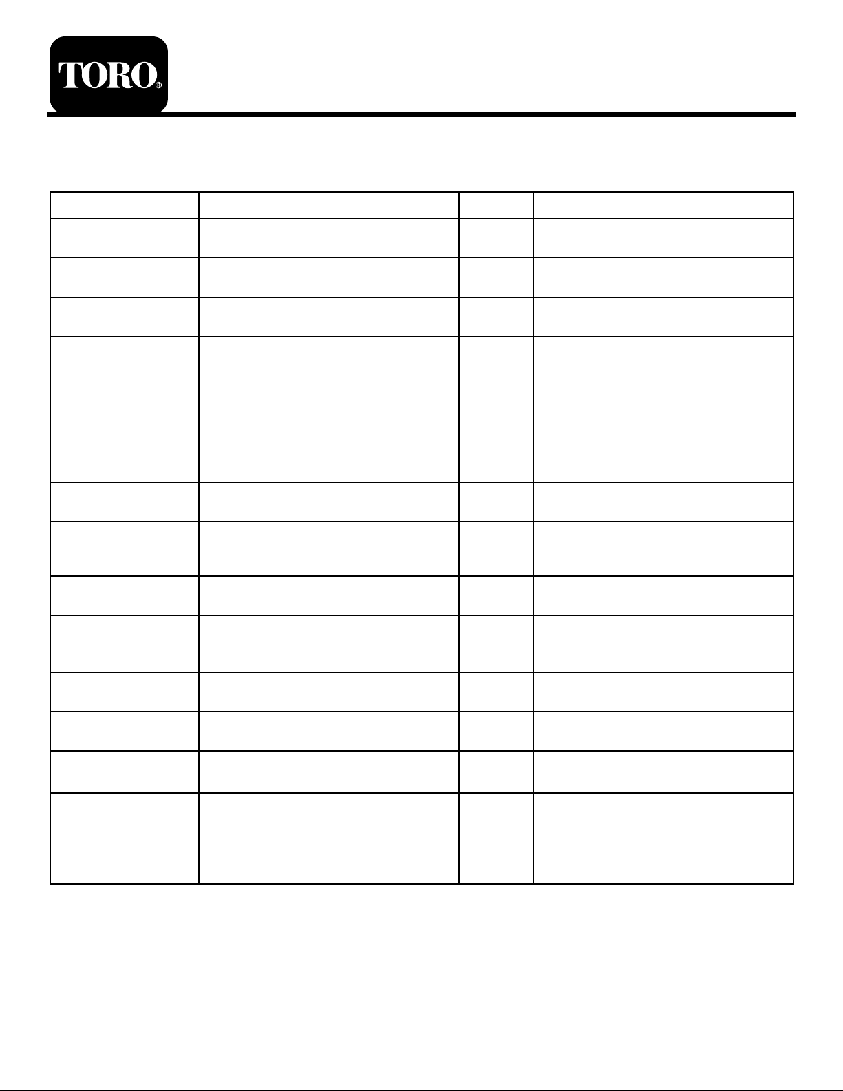
LooseParts
Usethechartbelowtoverifythatallpartshavebeenshipped.
FormNo.3361-750RevA
®
Mowers
SetupInstructions
ProcedureDescription
1
2
3
4
5
6
7
Qty.
Nopartsrequired
Nopartsrequired
Rearwheels2Installthedrivewheels.
Rollbar,rightsection1
Rollbar,leftsection
Rollbar,centersection1
Bolt,(3/8x1inch)
Curvedwasher
Flangenut,(3/8inch)
Bolt,(1/2x3–1/4inch)
Flangenut,(1/2inch)
Nopartsrequired
J-bolt2
Wingnut2
Holddownclamp1
Nopartsrequired
–
–
1
8
8
8
2
2
–
–
Removepartsfromthecrate.
Checkthetirepressure.
InstalltheRolloverProtectionSystem
(ROPS).
Addfueltothemachine.
Installabattery
Chargethebattery.
Use
Number2generalpurposelithiumbase
8
9
10
11
12
ormolybdenumbasegrease.(Purchase
separately.)
Nopartsrequired
Nopartsrequired
Nopartsrequired
Operator’sManual
EngineOwner’sManual
RegistrationCard
Operatortrainingmaterial
Key2
1tube
–
–
–
1
1
1
1
Checkthemachineforgrease.
Checktheengineoillevel.
Preparethesidedischargechute.
Checkthemachinebeforedeliveryto
thecustomer.
Deliveringthemachinetothecustomer.
©2009—TheToro®Company
8111LyndaleAvenueSouth
Bloomington,MN55420
Registeratwww.Toro.com.
OriginalInstructions(EN)
PrintedintheUSA.
AllRightsReserved
Page 2
1
3
RemovingPartsfromtheCrate
NoPartsRequired
Procedure
RemovethetiresandthepartsfortheROPSfromthe
shippingcrate.
2
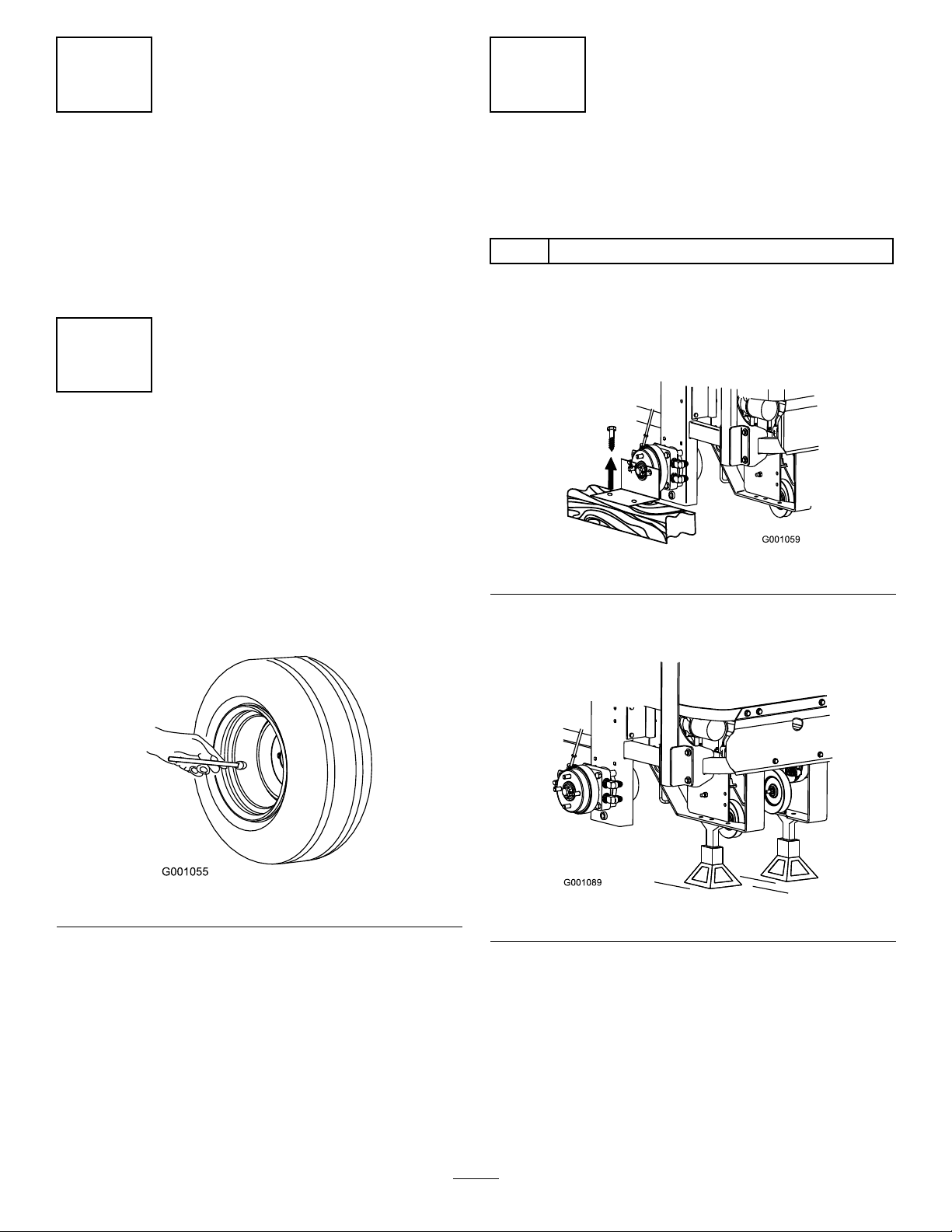
CheckingtheTirePressure
NoPartsRequired
Procedure
Pressure:13psi(90kPa)
Note:Thefrontcasterwheelisasemi-pneumatictire
anddoesnotneedtobechecked.
Checktheairpressureinthedrivetires.
RaisingtheMachineUpand
InstallingtheDriveWheels
Partsneededforthisprocedure:
2Rearwheels
Procedure
1.Removethescrewsholdingtherightangleretaining
platetothecrate.
Figure2
2.Raisethebackofthemachineupandsupportitwith
jack-stands.
Figure1
Figure3
3.Removethewheelnutsfrombothsidesofthe
vehicleandremovetherightangleretainingplate.
Discardthescrewsandretainingplate.
2
Page 3
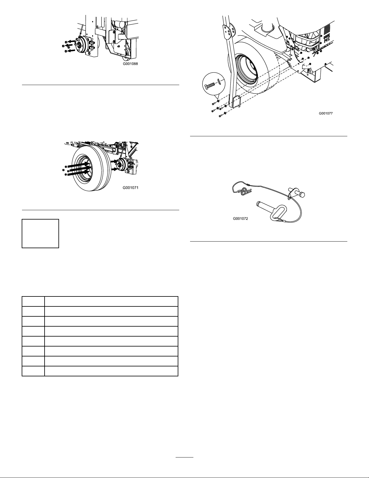
Figure4
4.Mountthewheelswiththevalvestemtotheoutside
andsecurethemwiththewheelnutspreviously
removed.
5.Torquethewheelnutsto95ft-lb(128N·m).
6.Removethejack-stands.
Figure5
4
InstallingtheRollOver
ProtectionSystem
Partsneededforthisprocedure:
Figure6
2.Installthelanyardclipsontothelongbolts(1/2x
3-1/4inch).
Note:Makesurethebenttabpointstowardthe
headofthebolt.
Figure7
3.Lightlyoiltheendsofthecenterrollbarsection.
4.Looselyinstallthecenterrollbarsectionusing2
bolts(1/2x3-1/4inch)and2angenuts(1/2inch).
Note:Makesuretheboltsareinstalledfromthe
outsideoftherollbar.
1Rollbar,rightsection
1
Rollbar,leftsection
1Rollbar,centersection
8
Bolt,(3/8x1inch)
8
Curvedwasher
8
Flangenut,(3/8inch)
2
Bolt,(1/2x3–1/4inch)
2
Flangenut,(1/2inch)
Procedure
1.Looselyinstalltherightandleftrollbarsectionto
theframe,with8bolts(3/8x1inch),8curved
washers,and8angenuts(3/8inch).
Note:Thecurvewasherconemustbeinstalled
towardthebolthead.
Note:Makesurethelanyardtabisinstalledasshow
andpointsforward.
3
Page 4
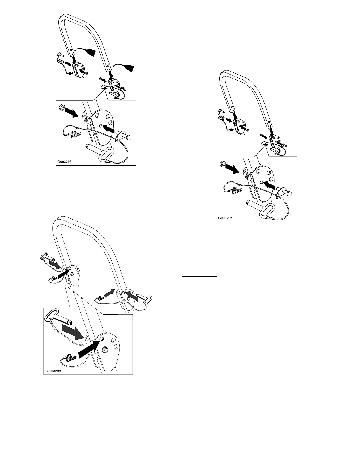
Figure8
6.Torquealllowerfasteners,attachedtothemachine
frame,to30ft-lb.
7.Tightenthecenterrollbarbolts(1/2x3-1/4inch)
soitrotatesfreelywithsomeresistance.
Note:Nomorethanonethreadshouldbeexposed
outsidethenut.
5.Raisetherollbarintotheuprightpositionandsecure
itwiththepinsandhairpincotterpinsfastenedto
thelanyards
Figure10
5
AddingFueltotheMachine
NoPartsRequired
Procedure
Addfueltothemachinebeforestartingit.Refertoyour
Operator’sManual.forthecorrectfuelandprocedure.
Figure9
4
Page 5
6
InstallingaBattery
Partsneededforthisprocedure:
2J-bolt
2Wingnut
1Holddownclamp
Procedure
Purchasea12Vbatteryandinstallitintothemachine.
Theenginerequiresaminimumof540CCA.
Figure11
Usethehardwareincludedtoinstallthenewbattery.
RefertoInstallingtheBatteryintheOperator’sManual.
7
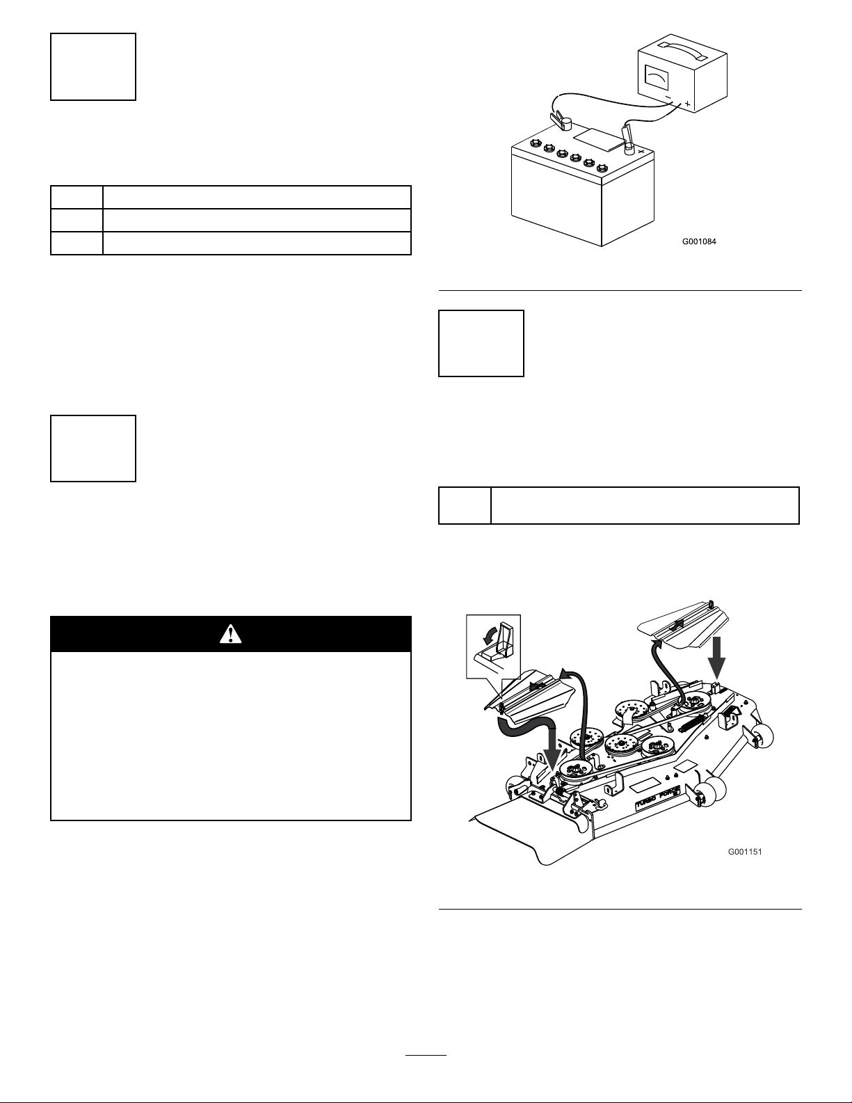
ChargingtheBattery
NoPartsRequired
Procedure
Chargingthebatteryproducesgassesthatcan
explodeandcauseseriousinjury.
•Keepcigarettes,sparksandamesaway
fromthebattery.
•Makesuretheignitionswitchisoff.
8
CheckingtheMachinefor
Grease
Partsneededforthisprocedure:
1tube
Procedure
1.Removethebeltcoversasshownbelow .
Number2generalpurposelithiumbaseor
molybdenumbasegrease.(Purchaseseparately .)
•Ventilatewhenchargingorusingthebattery
inanenclosedspace.
Important:Donotrunthemachinewiththe
batterydisconnected;electricaldamagemayoccur
totheengine.
Chargethebattery.RefertotheOperator’ sManualfor
instructions.
Figure12
2.Checkthetensioningarmforgrease.
3.Checkthegreaseforthethreespindlebearings.If
needed,addgreaseuntilitcomesoutofthelower
seals.
4.Installthebeltcovers.
5
Page 6
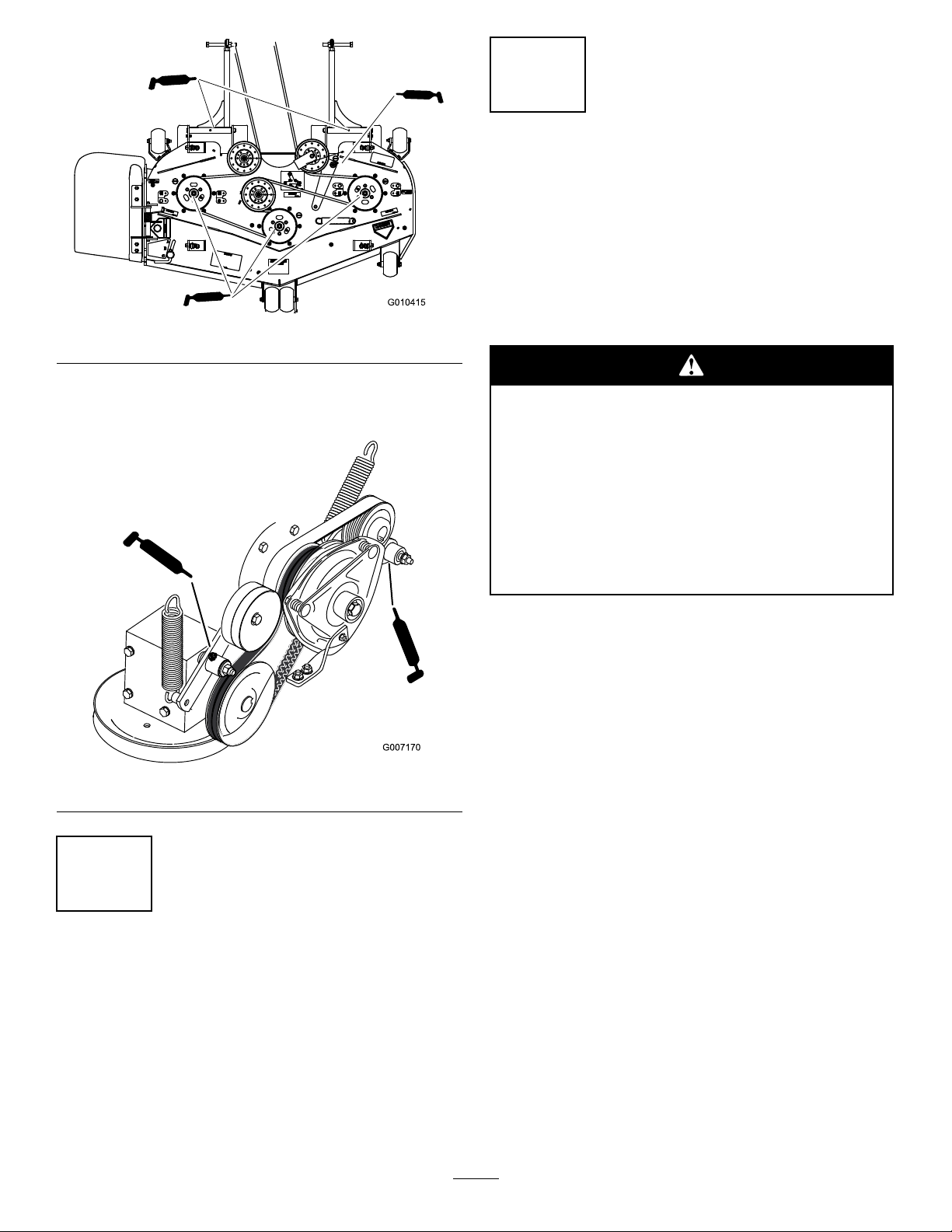
Figure13
10
CheckingtheSideDischarge
Chute
NoPartsRequired
Procedure
Ifthereareplastictiesholdingthesidedischargechute
up,removethemandlowerthechuteintoplace.
5.Checkthegreaseforthepumpdrivebeltidlerarm.
6.CheckthegreaseforthePTOdrivebeltidlerarm.
Figure14
Anuncovereddischargeopeningcouldallow
thelawnmowertothrowobjectsinthe
operator’sorbystander’sdirectionandresultin
seriousinjuryordeath.Also,contactwiththe
bladecouldoccur.
Neveroperatethelawnmowerwiththegrass
deectorremovedunlessyouinstallacover
plate,amulchplate,oragrasschuteand
catcher.
1.MakesuretheLendofspringisinstalledbehind
thedeckedgebeforeinstallingtheboltasshownin
Figure15.
2.PlacetheJhookendofspringaroundgrassdeector
(Figure15).
Important:Thegrassdeectormustbefreeto
rotatewithdownwardtension.Liftthedeector
uptothefullopenpositionandensurethatit
rotatesfreely,withoutbindingintothefulldown
position.
9
CheckingtheEngineOilLevel
NoPartsRequired
Procedure
Beforeyoustarttheengineandusethemachine,check
theoillevelintheenginecrankcase;refertoChecking
OilLevelinOperator’ sManual.
6
Page 7
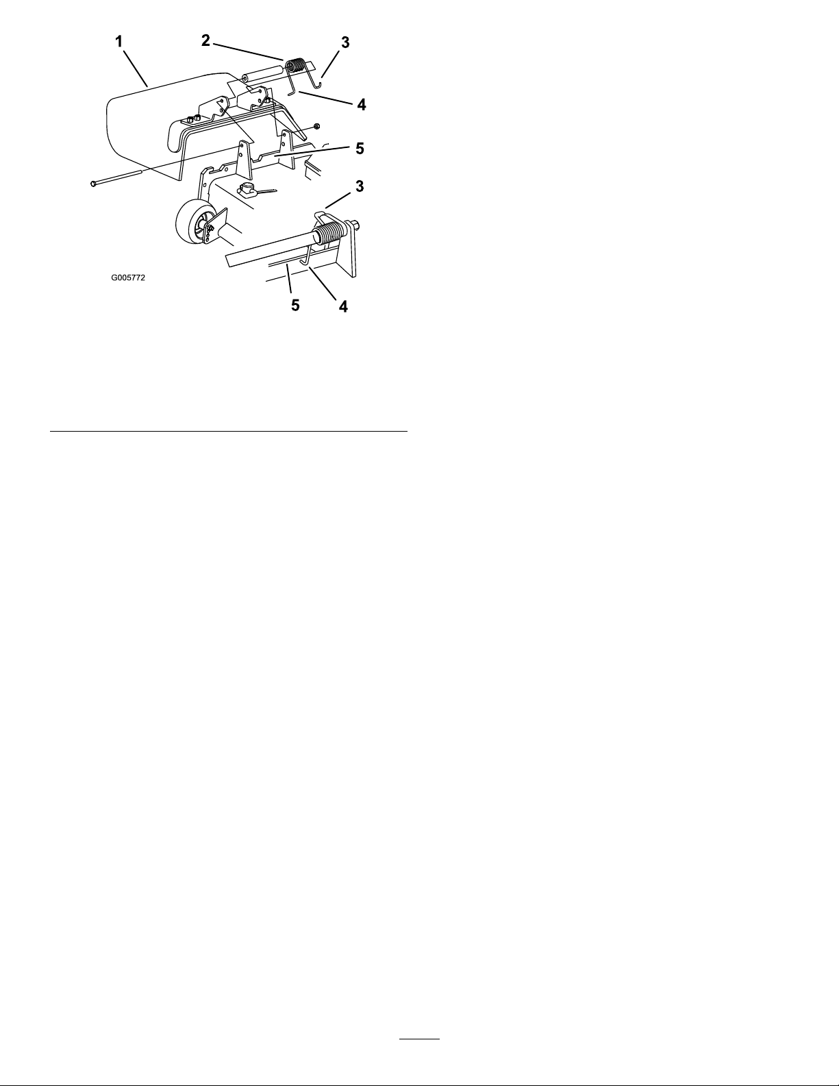
Figure15
1.GrassDeector4.Lendofspring,place
2.Spring
3.Jhookendofspring
behinddeckedgebefore
installingbolt
5.Deckedge
7
Page 8

11
CheckingtheMachineBeforeDeliverytotheCustomer
NoPartsRequired
Procedure
Beforedeliveringthemachinetothecustomer,ensurethatyouperformorhaveperformedtheprocedureslistedin
thefollowingtableandinitialeachwhennished.RefertotheOperator’sManualforinstructionsonperforming
theseprocedures.
Initial
Checkthetirepressure.
Checkthelevelofthemower.
Checkthatallmowerspindlesaregreased.
Checktheengineoillevel.
Checkthehydraulicuidlevel.
CheckROPSissecure.
Onliquidcooledmachines,checkthelevelofthecoolantintheradiatorandoverowbottle.
Checktheadjustmentoftheparkingbrake.
Ensurethatthemachinetrackscorrectly;refertotheOperator’sManualfortheadjustmentprocedure.
Checkthesafetyinterlocksystem;refertotheOperator’sManual.
EnsurethatthePTOworks.
Checkallfastenersyouinstalledtoensurethattheyaretight.
CheckProcedure
Whenyounishsettingupthemachine,signanddateinthespaceprovidedbelow:
Signature:Date:
8
Page 9

12
DeliveringtheMachinetotheCustomer
Partsneededforthisprocedure:
1
Operator’sManual
1
EngineOwner’sManual
1
RegistrationCard
1
Operatortrainingmaterial
2Key
Procedure
Atdelivery,Fillinthemodelandserialnumberandcompletetheitemslistedinthefollowingtableandinitial
eachwhennished.
ModelNo.SerialNo.
9
Page 10

DealerInitial
CustomerInitialCheckProcedure
Showthecustomerwherethefollowingfeaturesarelocatedandhowtheyfunction:
Fueltankcaps
Oilllcap/Oildipstick
Engineoillter
Engineoildrain
Fuellters
Airlter
Radiatorcoolant
Hydraulicuidreservoir
Hydrauliclter
Battery
Ignitionswitch
Throttlelever
Glowpluglightandswitch
Powertakeoffswitch(PTO)
Motioncontrollevers
Parkingbrake
Mowerheight-of-cut
Liftassistlever
ZStand®(OnlyonInternationalmachines)
Adjustableseat
Hydraulicbypassvalves
RolloverProtectionSystem(ROPS)
Mowerdeckowbafe
RefertotheOperator’sManualtopointoutsafetyprocedures,operation,and
maintenanceprocedures.
ReviewthewarrantystatementasshownintheOperator’sManual.
Describethepostsaleserviceproceduresforyourstore.
Assistthecustomerinllingoutandmailingtheregistrationcardorregisteronlineat
www.T oro.com
MakesurethatthecustomerreceivestheOperator’sManual,EngineOwner’sManual,
SetUpInstructions,andoperatortrainingmaterial.
MakesurethecustomerknowsthePartsCatalogisavailableatwww.Toro.com
Assistthecustomerinloadingthemower.
Note:Whenyou,thedealerrepresentative,havenisheddeliveringthemachinetothecustomer,signanddatein
thespaceprovidebelowandkeepacopyofthispagefordealerrecords.
Signature:
Signature:Date:
Date:
10
Page 11

Notes:
11
Page 12

 Loading...