

Page 1
FormNo.3375-556RevA
ZMaster
®
Commercial2000
SeriesRidingMower
with48inTURBOFORCE
®
SideDischarge
Mower
ModelNo.74141TE—SerialNo.313000001andUp
Registeratwww.T oro.com.
OriginalInstructions(EN)
*3375-556*A
Page 2
ThisproductcomplieswithallrelevantEuropeandirectives,
fordetailspleaseseetheseparateproductspecicDeclaration
ofConformity(DOC)sheet.
ThissparkignitionsystemcomplieswithCanadianICES-002.
WARNING
Removingstandardoriginalequipmentpartsand
accessoriesmayalterthewarranty,traction,and
safetyofthemachine.FailuretouseoriginalToro
partscouldcauseseriousinjuryordeath.Making
unauthorizedchangestotheengine,fuelorventing
system,mayviolateregulations.
Replaceallpartsincluding,butnotlimitedto,tires,
belts,blades,andfuelsystemcomponentswith
originalT oroparts.
Introduction
Thisrotary-blade,ridinglawnmowerisintendedtobeused
byresidentialhomeownersorprofessional,hiredoperators.
Itisdesignedprimarilyforcuttinggrassonwell-maintained
lawnsonresidentialorcommercialproperties.Itisnot
designedforcuttingbrushorforagriculturaluses.
Readthisinformationcarefullytolearnhowtooperateand
maintainyourproductproperlyandtoavoidinjuryand
productdamage.Youareresponsibleforoperatingthe
productproperlyandsafely.
YoumaycontactTorodirectlyatwww .Toro.comforproduct
andaccessoryinformation,helpndingadealer,ortoregister
yourproduct.
Wheneveryouneedservice,genuineToroparts,oradditional
information,contactanAuthorizedServiceDealerorToro
CustomerServiceandhavethemodelandserialnumbersof
yourproductready .Figure1identiesthelocationofthe
modelandserialnumbersontheproduct.Writethenumbers
inthespaceprovided.
g017416
1
Figure1
1.Modelandserialnumberlocation
ModelNo.
SerialNo.
Thismanualidentiespotentialhazardsandhassafety
messagesidentiedbythesafetyalertsymbol(Figure2),
whichsignalsahazardthatmaycauseseriousinjuryordeath
ifyoudonotfollowtherecommendedprecautions.
Figure2
1.Safetyalertsymbol
Thismanualuses2otherwordstohighlightinformation.
Importantcallsattentiontospecialmechanicalinformation
andNoteemphasizesgeneralinformationworthyofspecial
attention.
©2013—TheToro®Company
8111LyndaleAvenueSouth
Bloomington,MN55420
2
Contactusatwww.Toro.com.
PrintedintheUSA
AllRightsReserved
Page 3

Contents
Introduction..................................................................2
Safety...........................................................................4
SafeOperatingPractices...........................................4
ToroRidingMowerSafety........................................5
SoundPressure.......................................................6
SoundPower..........................................................6
VibrationLevel.......................................................6
SlopeIndicator.......................................................7
SafetyandInstructionalDecals.................................8
ProductOverview.........................................................12
Controls...............................................................12
Specications........................................................13
Operation....................................................................13
AddingFuel...........................................................13
CheckingtheEngineOilLevel.................................14
BreakingInaNewMachine.....................................15
UsingtheRolloverProtectionSystem(ROPS)............15
ThinkSafetyFirst...................................................15
OperatingtheParkingBrake....................................16
OperatingtheMowerBladeControlSwitch
(PTO)...............................................................17
OperatingtheThrottle............................................17
OperatingtheChoke...............................................17
OperatingtheIgnitionSwitch..................................17
UsingtheFuelShut-OffValve..................................18
StartingandStoppingtheEngine..............................18
TheSafetyInterlockSystem.....................................19
DrivingForwardorBackward..................................20
StoppingtheMachine.............................................21
AdjustingtheHeightofCut.....................................21
AdjustingtheAnti-ScalpRollers...............................22
PositioningtheSeat................................................23
UsingtheDriveWheelReleaseValves.......................23
UsingtheSideDischarge.........................................24
LoadingMachines..................................................24
TransportingMachines............................................25
OperatingTips......................................................26
Maintenance.................................................................27
RecommendedMaintenanceSchedule(s)......................27
Lubrication...............................................................28
GreasingandLubrication........................................28
WheretoGreasetheMower.....................................28
LubricatetheCasterWheelHubs..............................29
EngineMaintenance..................................................30
ServicingtheAirCleaner.........................................30
ServicingtheEngineOil..........................................31
ServicingtheSparkPlug..........................................33
CheckSparkArrester(ifequipped)............................34
FuelSystemMaintenance...........................................34
ReplacingtheFuelFilter..........................................34
ServicingtheFuelTank...........................................35
ElectricalSystemMaintenance....................................35
ServicingtheBattery...............................................35
ServicingtheFuses.................................................36
DriveSystemMaintenance.........................................37
CheckingtheSeatBelt.............................................37
CheckingtheRolloverProtectionSystem(ROPS)
Knobs...............................................................37
AdjustingtheTracking............................................38
CheckingtheTirePressure......................................38
AdjustingtheCasterPivotBearing............................39
AdjustingtheElectricClutch....................................39
CoolingSystemMaintenance......................................40
CleaningtheEngineScreen......................................40
CleaningtheEngineCoolingFinsand
Shrouds.............................................................40
BeltMaintenance......................................................40
InspectingtheBelts................................................40
ReplacingtheMowerBelt........................................40
ReplacingtheHydraulicPumpDriveBelt...................41
ControlsSystemMaintenance.....................................42
AdjustingtheControlHandlePosition......................42
AdjustingtheMotionControlLinkage......................43
AdjustingtheMotionControlDamper......................43
AdjustingtheMotionControlNeutralLock
Pivot.................................................................44
HydraulicSystemMaintenance....................................44
ServicingtheHydraulicSystem.................................44
ChangingtheHydraulicSystemFilterand
Oil....................................................................45
MowerDeckMaintenance...........................................46
LevelingtheMowerDeck........................................46
ServicingtheCuttingBlades.....................................48
RemovingtheMowerDeck.....................................51
ReplacingtheGrassDeector..................................52
Cleaning...................................................................52
CleaningUndertheMower......................................52
WasteDisposal.......................................................52
Storage........................................................................53
CleaningandStorage..............................................53
Troubleshooting...........................................................54
Schematics...................................................................56
3
Page 4

Safety
ThismachinemeetsorexceedsEuropeanStandardsin
effectatthetimeofproduction.However,improperuse
ormaintenancebytheoperatororownercanresultin
injury.Toreducethepotentialforinjury,complywiththese
safetyinstructionsandalwayspayattentiontothesafety
alertsymbol,whichmeansCAUTION,WARNING,or
DANGER-"personalsafetyinstruction."Failuretocomply
withtheinstructionmayresultinpersonalinjuryordeath.
SafeOperatingPractices
ThefollowinginstructionsarefromtheCENstandardEN
836:1997.
Thisproductiscapableofamputatinghandsandfeetand
throwingobjects.Alwaysfollowallsafetyinstructionsto
avoidseriousinjuryordeath.
Training
•Readtheinstructionscarefully.Befamiliarwiththe
controlsandtheproperuseoftheequipment.
•Neverallowchildrenorpeopleunfamiliarwiththese
instructionstousethelawnmower.Localregulationscan
restricttheageoftheoperator.
•Nevermowwhilepeople,especiallychildren,orpetsare
nearby.
•Keepinmindthattheoperatororuserisresponsiblefor
accidentsorhazardsoccurringtootherpeopleortheir
property.
•Donotcarrypassengers.
•Alldriversshouldseekandobtainprofessionaland
practicalinstruction.Suchinstructionshouldemphasize:
–theneedforcareandconcentrationwhenworking
withride-onmachines;
–controlofaride-onmachineslidingonaslopewill
notberegainedbytheapplicationofthecontrol
levers.Themainreasonsforlossofcontrolare:
◊insufcientwheelgrip,especiallyonwetgrass;
◊beingdriventoofast;
◊inadequatebraking;
◊thetypeofmachineisunsuitableforitstask;
◊lackofawarenessoftheeffectofground
conditions,especiallyslopes;
◊incorrecthitchingandloaddistribution.
Preparation
•Whilemowing,alwayswearsubstantialfootwearandlong
trousers.Donotoperatetheequipmentwhenbarefoot
orwearingopensandals.
•Thoroughlyinspecttheareawheretheequipmentisto
beusedandremoveallobjectswhichmaybethrownby
themachine.
•Warning–Fuelishighlyammable.
–Storefuelincontainersspecicallydesignedforthis
purpose.
–Refueloutdoorsonlyanddonotsmokewhile
refuelling.
–Addfuelbeforestartingtheengine.Neverremove
thecapofthefueltankoraddfuelwhiletheengineis
runningorwhentheengineishot.
–Iffuelisspilled,donotattempttostarttheengine
butmovethemachineawayfromtheareaofspillage
andavoidcreatinganysourceofignitionuntilfuel
vaporshavedissipated.
–Replaceallfueltanksandcontainercapssecurely.
•Replacefaultysilencers.
•Beforeusing,alwaysvisuallyinspecttoseethattheblades,
bladeboltsandcutterassemblyarenotwornordamaged.
Replacewornordamagedbladesandboltsinsetsto
preservebalance.
•Onmulti-bladedmachines,takecareasrotatingoneblade
cancauseotherbladestorotate.
Operation
•Lightningcancausesevereinjuryordeath.Iflightning
isseenorthunderisheardinthearea,donotoperate
themachine;seekshelter.
•Bealert,slowdownandusecautionwhenmakingturns.
Lookbehindandtothesidebeforechangingdirections.
•Donotoperatetheengineinaconnedspacewhere
dangerouscarbonmonoxidefumescancollect.
•Mowonlyindaylightoringoodarticiallight.
•Beforeattemptingtostarttheengine,disengageallblade
attachmentclutchesandshiftintoneutral.
•Donotuseonslopesgreaterthan15degrees.
•Rememberthereisnosuchthingasasafeslope.Travel
ongrassslopesrequiresparticularcare.Toguardagainst
overturning:
–-donotstoporstartsuddenlywhenonaslope;
–-useslowspeedsonslopesandduringtightturns;
–-stayalertforhumpsandhollowsandotherhidden
hazards;
•Usecarewhenpullingloadsorusingheavyequipment.
–-Useonlyapproveddrawbarhitchpoints.
–-Limitloadstothoseyoucansafelycontrol.
–-Donotturnsharply.Usecarewhenreversing.
•Watchoutfortrafcwhencrossingornearroadways.
•Stopthebladesrotatingbeforecrossingsurfacesother
thangrass.
•Whenusinganyattachments,neverdirectdischargeof
materialtowardbystandersnorallowanyonenearthe
machinewhileinoperation.
4
Page 5

•Neveroperatethemachinewithdamagedguardsor
withoutsafetyprotectivedevicesinplace.
•Donotchangetheenginegovernorsettingsoroverspeed
theengine.Operatingtheengineatexcessivespeedcan
increasethehazardofpersonalinjury.
•Beforeleavingtheoperator'sposition:
–disengagethepowertake-offandlowerthe
attachments;
–changeintoneutralandsettheparkingbrake;
–stoptheengineandremovethekey .
•Disengagedrivetoattachments,stoptheengine,and
disconnectthesparkplugwire(s)orremovetheignition
key
–beforeclearingblockagesoruncloggingchute;
–beforechecking,cleaningorworkingonthe
lawnmower;
–afterstrikingaforeignobject.Inspectthelawnmower
fordamageandmakerepairsbeforerestartingand
operatingtheequipment;ifthemachinestartsto
vibrateabnormally(checkimmediately).
•Disengagedrivetoattachmentswhentransportingornot
inuse.
•Stoptheengineanddisengagedrivetoattachment
–beforerefuelling;
–beforeremovingthegrasscatcher;
–beforemakingheightadjustmentunlessadjustment
canbemadefromtheoperator'sposition.
•Reducethethrottlesettingduringenginerun-outand,if
theengineisprovidedwithashut-offvalve,turnthefuel
offattheconclusionofmowing.
MaintenanceandStorage
•Keepallnuts,boltsandscrewstighttobesurethe
equipmentisinsafeworkingcondition.
•Neverstoretheequipmentwithfuelinthetankinsidea
buildingwherefumescanreachanopenameorspark.
•Allowtheenginetocoolbeforestoringinanyenclosure.
•Toreducetherehazard,keeptheengine,silencer,
batterycompartmentandfuelstorageareafreeofgrass,
leaves,orexcessivegrease.
•Checkthegrasscatcherfrequentlyforwearor
deterioration.
•Replacewornordamagedpartsforsafety.
•Ifthefueltankhastobedrained,thisshouldbedone
outdoors.
•Onmulti-bladedmachines,takecareasrotatingoneblade
cancauseotherbladestorotate.
•Whenmachineistobeparked,storedorleftunattended,
lowerthecuttingmeansunlessapositivemechanicallock
isused.
ToroRidingMowerSafety
ThefollowinglistcontainssafetyinformationspecictoToro
productsorothersafetyinformationthatyoumustknowthat
isnotincludedintheCENstandard.
•Engineexhaustcontainscarbonmonoxide,whichisan
odorless,deadlypoisonthatcankillyou.Donotrun
engineindoorsorinanenclosedarea.
•Keephands,feet,hairandlooseclothingawayfrom
attachmentdischargearea,undersideofmowerandany
movingpartswhileengineisrunning.
•Donottouchequipmentorattachmentpartswhichmay
behotfromoperation.Allowtocoolbeforeattempting
tomaintain,adjust,orservice.
•Batteryacidispoisonousandcancauseburns.Avoid
contactwithskin,eyesandclothing.Protectyourface,
eyes,andclothingwhenworkingwithabattery.
•Batterygasescanexplode.Keepcigarettes,sparksand
amesawayfrombattery.
•UseonlygenuineTororeplacementpartstoensurethat
originalstandardsaremaintained.
•UseonlyToro-approvedattachments.Warrantymaybe
voidedifusedwithunapprovedattachments.
SlopeOperation
•Donotmowslopesgreaterthan15degrees.
•Donotmowneardrop-offs,ditches,steepbanksor
water.Wheelsdroppingoveredgescancauserollovers,
whichmayresultinseriousinjury,deathordrowning.
•Donotmowslopeswhengrassiswet.Slippery
conditionsreducetractionandcouldcauseslidingand
lossofcontrol.
•Donotmakesuddenturnsorrapidspeedchanges.
•Useawalkbehindmowerand/orahandtrimmernear
drop-offs,ditches,steepbanksorwater.
•Reducespeedanduseextremecautiononslopes.
•Removeormarkobstaclessuchasrocks,treelimbs,etc.
fromthemowingarea.Tallgrasscanhideobstacles.
•Watchforditches,holes,rocks,dips,andrisesthatchange
theoperatingangle,asroughterraincouldoverturnthe
machine.
•Avoidsuddenstartswhenmowinguphillbecausethe
mowermaytipbackwards.
•Beawarethatlossoftractionmayoccurgoingdownhill.
Weighttransfertothefrontwheelsmaycausedrive
wheelstoslipandcauselossofbrakingandsteering.
•Alwaysavoidsuddenstartingorstoppingonaslope.
Iftireslosetraction,disengagethebladesandproceed
slowlyofftheslope.
5
Page 6

•Followthemanufacturer'srecommendationsforwheel
weightsorcounterweightstoimprovestability .
•Useextremecarewithgrasscatchersorotherattachments.
Thesecanchangethestabilityofthemachineandcause
lossofcontrol.
SoundPressure
Thisunithasasoundpressurelevelattheoperator’searof91
dBA,whichincludesanUncertaintyValue(K)of1dBA.
Thesoundpressurelevelwasdeterminedaccordingtothe
proceduresoutlinedinEN836.
SoundPower
Thisunithasaguaranteedsoundpowerlevelof105dBA,
whichincludesanUncertaintyValue(K)of1dBA.
Thesoundpowerlevelwasdeterminedaccordingtothe
proceduresoutlinedinISO11094.
VibrationLevel
Hand-Arm
Measuredvibrationlevelforrighthand=1.6m/s
2
Measuredvibrationlevelforlefthand=2.7m/s
2
UncertaintyValue(K)=1.4m/s
2
Measuredvaluesweredeterminedaccordingtotheprocedures
outlinedinEN836.
WholeBody
Measuredvibrationlevel=0.31m/s
2
UncertaintyValue(K)=0.16m/s
2
Measuredvaluesweredeterminedaccordingtotheprocedures
outlinedinEN836.
6
Page 7
SlopeIndicator
G011841
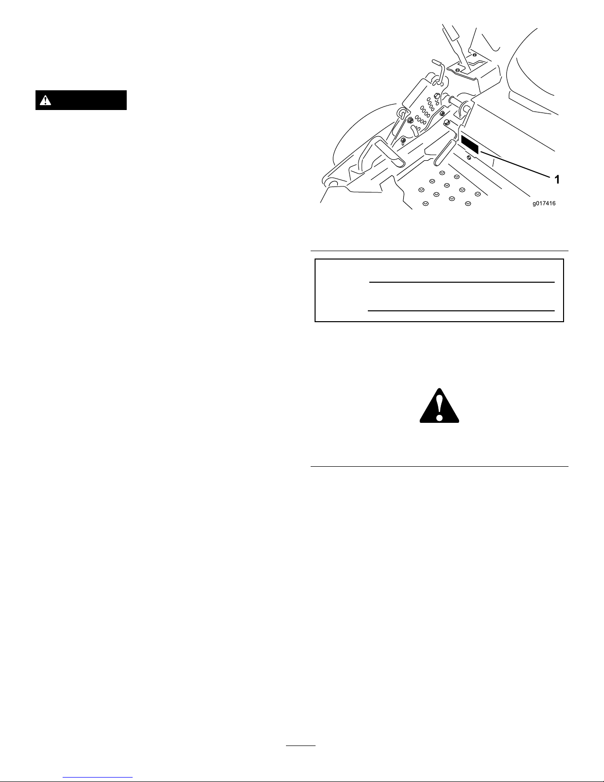
Figure3
Thispagemaybecopiedforpersonaluse.
1.Themaximumslopeyoucansafelyoperatethemachineonis15degrees.Usetheslopecharttodeterminethedegreeofslope
ofhillsbeforeoperating.Donotoperatethismachineonaslopegreaterthan15degrees.Foldalongtheappropriateline
tomatchtherecommendedslope.
2.Alignthisedgewithaverticalsurface,atree,building,fencepole,etc.
3.Exampleofhowtocompareslopewithfoldededge.
7
Page 8
SafetyandInstructional
Decals
Safetydecalsandinstructionsareeasilyvisibletotheoperatorandarelocatednearanyareaofpotential
danger.Replaceanydecalthatisdamagedorlost.
58-6520
1.Grease
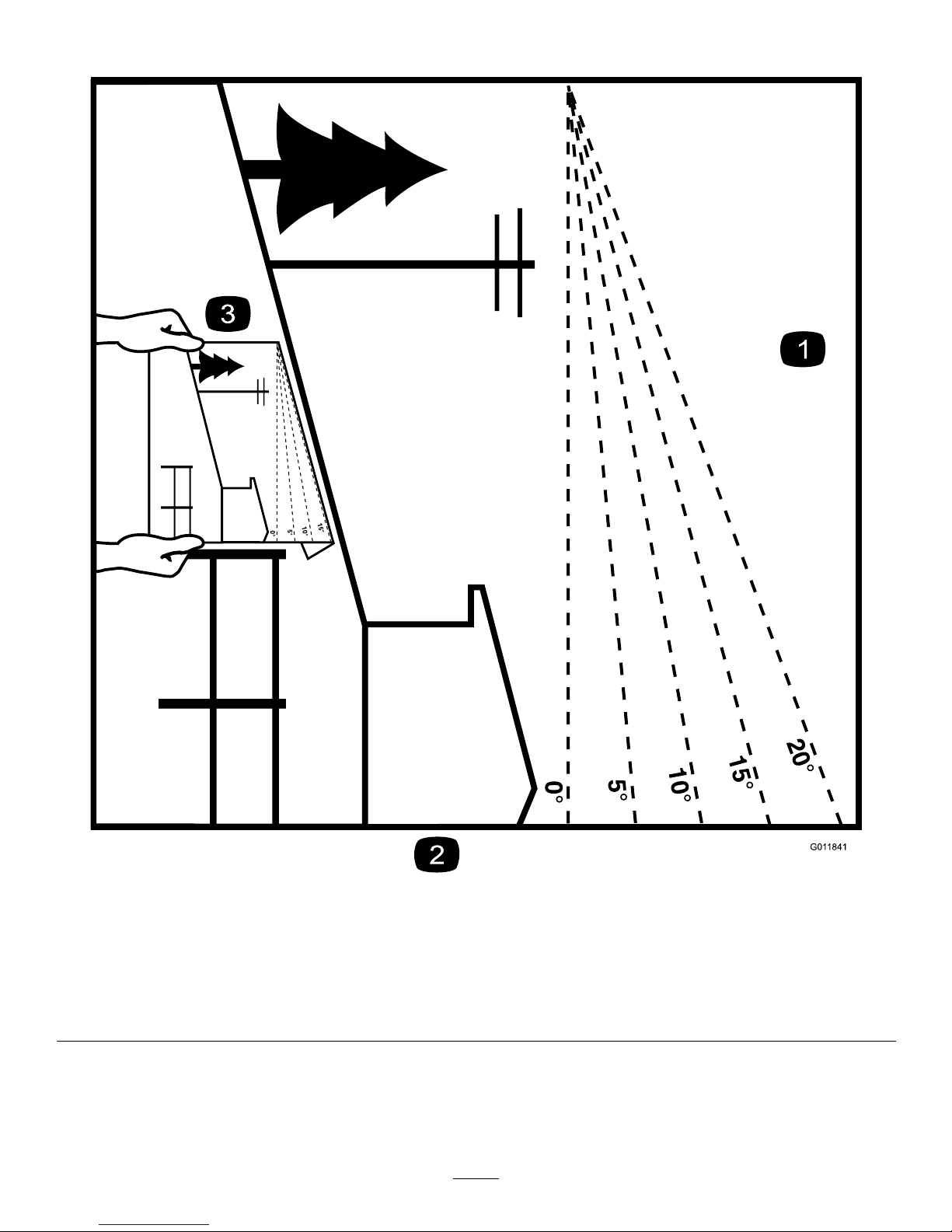
99-8936
1.Machinespeed4.Neutral
2.Fast5.Reverse
3.Slow
93-7818
1.Warning—readtheOperator'sManualforinstructionson
torquingthebladebolt/nutto85-1 10ft-lb(1 15-149N-m).
BatterySymbols
Someorallofthesesymbolsareonyourbattery
1.Explosionhazard
6.Keepbystandersasafe
distancefromthebattery .
2.Nore,opename,or
smoking.
7.Weareyeprotection;
explosivegasescan
causeblindnessandother
injuries
3.Causticliquid/chemical
burnhazard
8.Batteryacidcancause
blindnessorsevereburns.
4.Weareyeprotection9.Flusheyesimmediately
withwaterandgetmedical
helpfast.
5.ReadtheOperator's
Manual.
10.Containslead;donot
discard.
Manufacturer'sMark
1.Indicatesthebladeisidentiedasapartfromtheoriginal
machinemanufacturer.
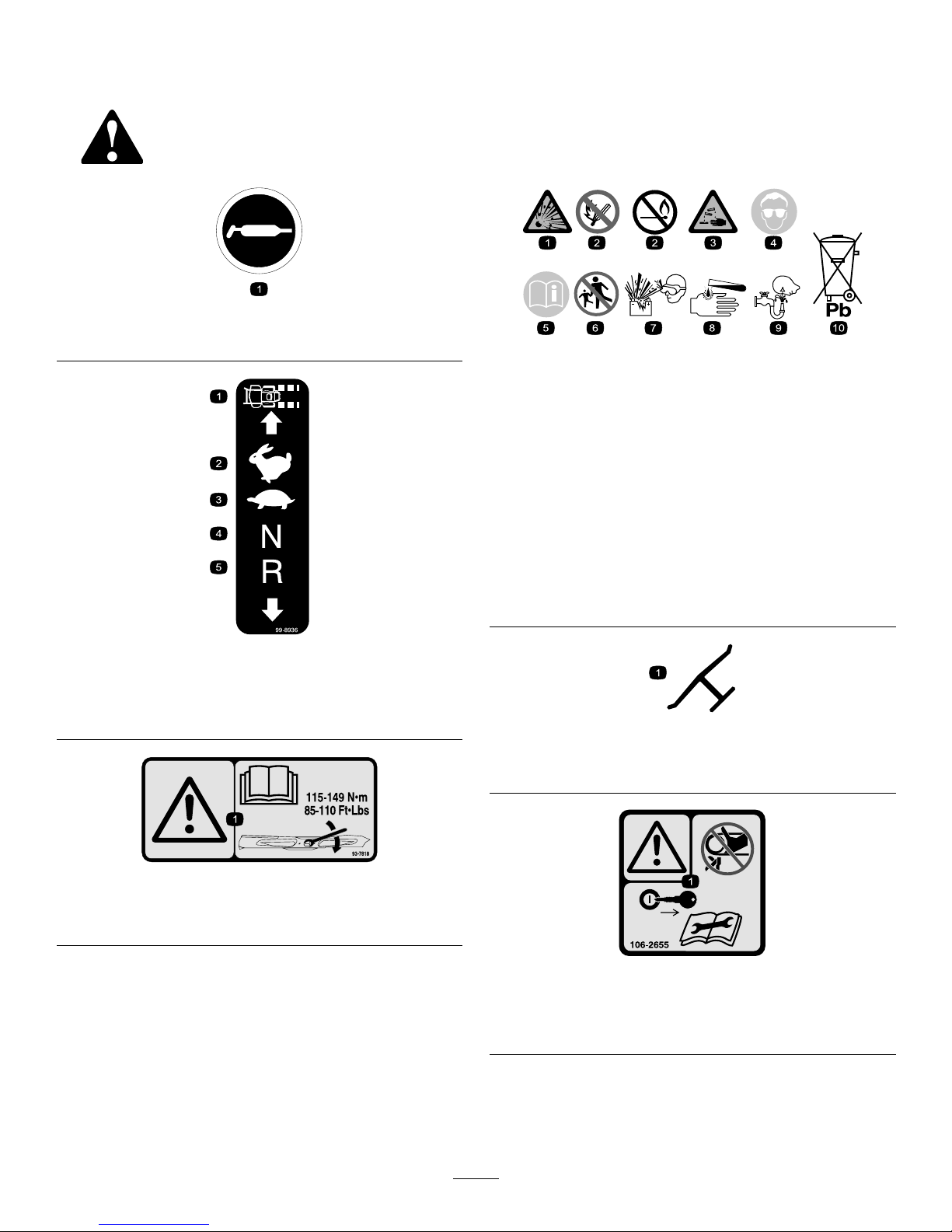
106–2655
1.Warning-donottouchorapproachmovingbelts;remove
theignitionkeyandreadtheinstructionsbeforeservicing
orperformingmaintenance.
8
Page 9
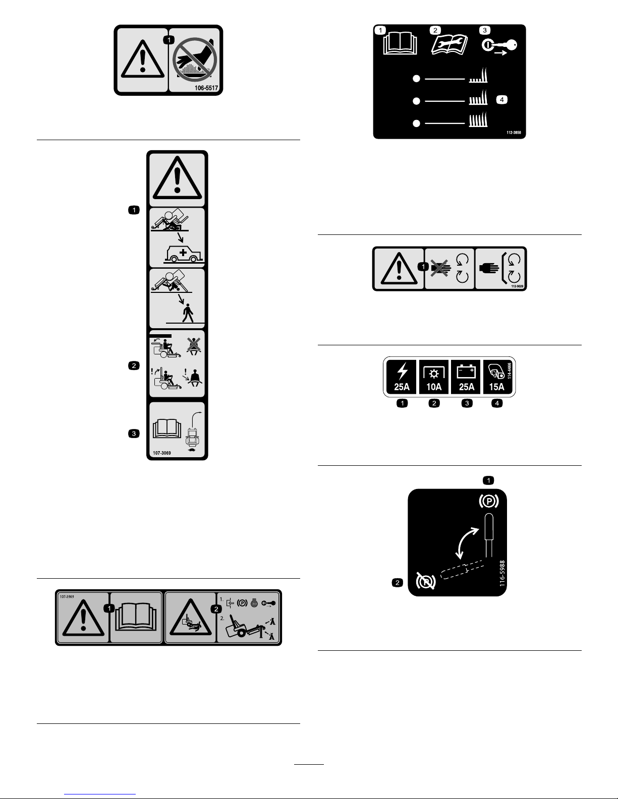
106-5517
1.Warning—donottouchthehotsurface.
107-3069
1.Warning–thereisnorolloverprotectionwhentherollbaris
down.
2.Toavoidinjuryordeathfromarolloveraccident,keepthe
rollbarinthefullyraisedandlockedpositionandwear
theseatbelt.Lowertherollbaronlywhenabsolutely
necessary;donotwearthetheseatbeltwhentherollbaris
down.
3.ReadtheOperator'sManual;driveslowlyandcarefully.
107–3969
1.Warning—readtheOperator'sManual.
2.Crushinghazard,mower—1)Engagetheparkingbrake,
stoptheengine,andremovetheignitionkey;2)Properly
jackthemachinebeforeworkingunderthemachine.
112-3858
1.ReadtheOperator's
Manual.
3.Removetheignitionkey
beforeadjustingtheheight
ofcut.
2.Readtheinstructions
beforeservicingor
performingmaintenance.
4.Heightofcutsettings.
112-9028
1.Warning—stayawayfrommovingparts;keepallguardsin
place.
114-4466
1.Main,25A
3.Charge,25A
2.PTO,10A
4.Auxiliary,15A
116-5988
1.Parkingbrake—engaged2.Parking
brake—disengaged
9
Page 10
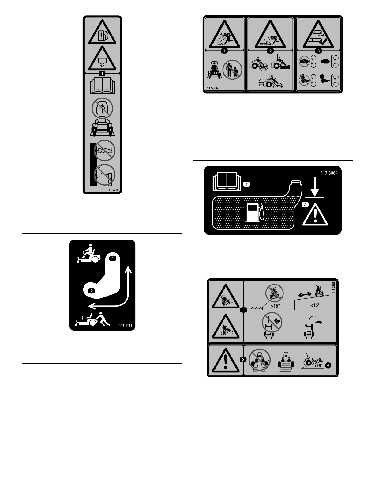
117-0346
1.Fuelleakhazard—readtheOperator'sManual;donot
attempttoremovetherollbar;donotweld,drillormodify
therollbarinanyway .
117–1158
1.Bypassleverpositionfor
operatingthemachine.
2.Bypassleverpositionfor
pushingthemachine.
117-3848
1.Thrownobjecthazard—keepbystandersasafedistance
fromthemachine.
2.Thrownobjecthazard,mower—donotoperatethewithout
deector,dischargecoverorgrasscollectionsystemin
place.
3.Cutting/dismembermentofhandorfoot—stayawayfrom
movingparts;keepallguardsandshieldsinplace.
117–3864
1.ReadtheOperator’s
Manual.
2.Filltobottomofllerneck;
warning—donotoverll
thetank.
117-3888
1.Sliding,tippinghazard—donotusethemachinenear
drop-offswithslopesgreaterthan15degrees,usethe
machineasafedistancefromdrop-offsonslopeslessthan
15degrees;donotturnsharplywhiletravelingfast,drive
slowlywhenturning.
2.Warning—donotusedualramps,useonepieceramps
whentransportingmachine;donotuserampswith
inclinationgreaterthan10degrees.
10
Page 11
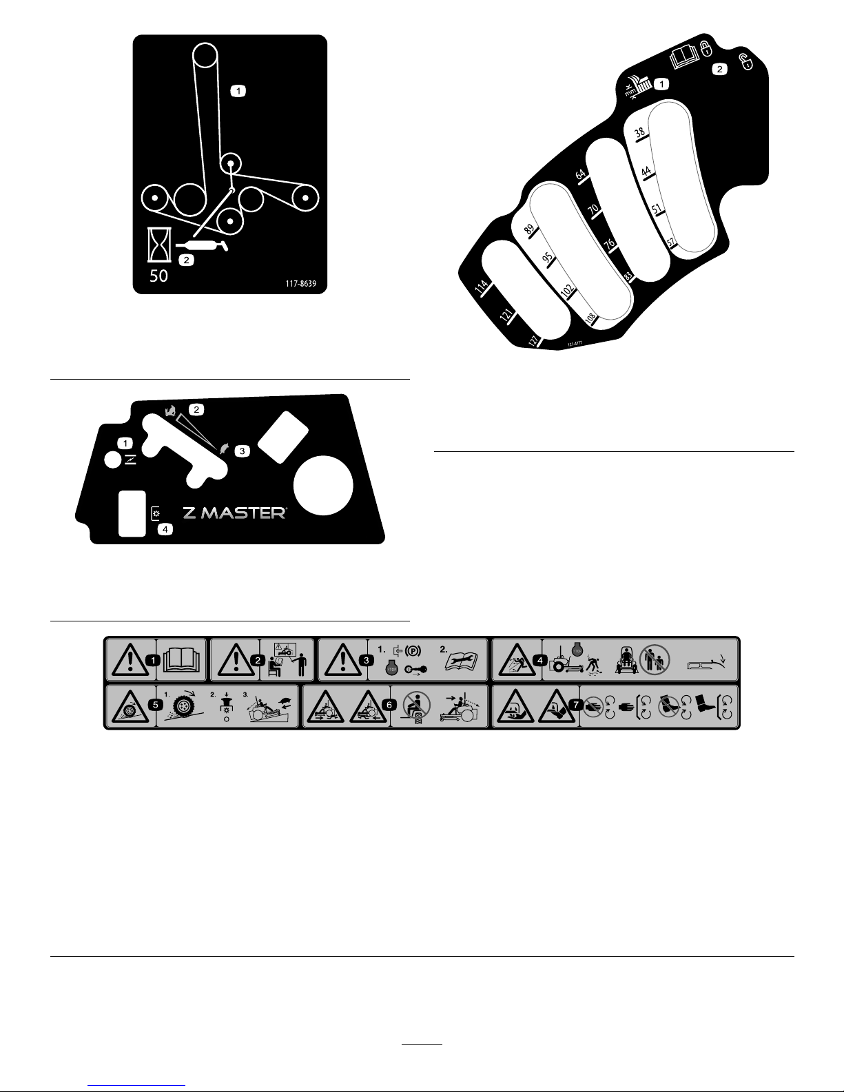
117-8639
1.Beltrouting
2.Greasepulley,
maintenanceinterval—50
hours
119-2501
1.Choke3.Slow
2.Fast
4.PTO(PowerT ake-off)
121–4777
1.Heightofcutadjustment2.ReadtheOperator’s
Manualoninformationon
howtolockandunlockthe
deckposition.
114–4468
1.Warning—readtheOperator'sManual.5.Lossoftraction/controlhazard,slopes—lossoftraction/control
onaslope,disengagethebladecontrolswitch(PTO),
proceedofftheslopeslowly .
2.Warning—donotoperatethismachineunlessyouaretrained.
6.Crushing/dismembermenthazardofbystanders—donotcarry
passengers,lookforwardanddownwhenoperatingthe
machine,lookbehindanddownwhenreversing.
3.Warning—engagetheparkingbrake,stoptheengineand
removetheignitionkey;readtheinstructionsbeforeservicing
orperformingmaintenance.
7.Cutting/dismembermenthazard;handorfoot—stayaway
frommovingpartsandkeepallguardsandshieldsinplace.
4.Thrownobjecthazard—Stoptheengineandpickupdebris
beforeoperating,keepbystandersasafedistancefromthe
machine,keepdeectorinplace
11
Page 12
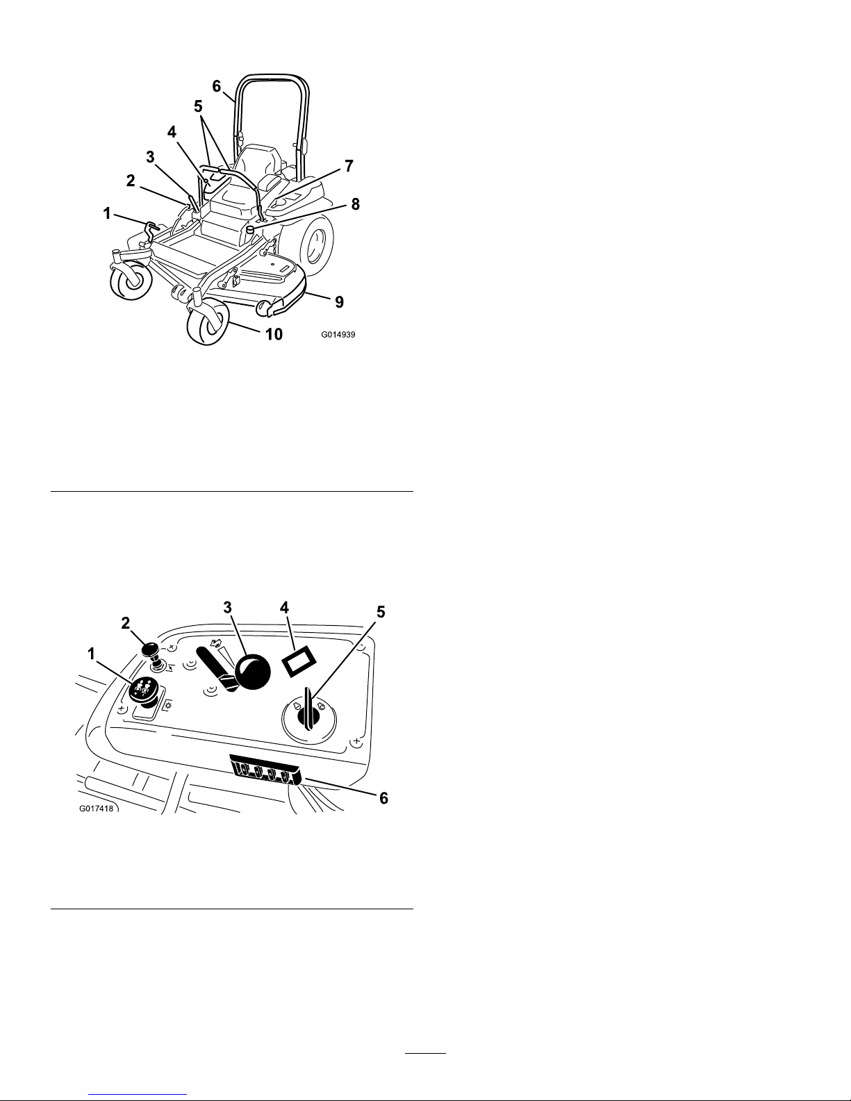
ProductOverview
G014939
Figure4
1.Height-of-cutdecklift
pedal
6.Rollbar
2.Transportlock
7.Seatbelt
3.Parkingbrakelever8.Fuelcap
4.Controls
9.Mowerdeck
5.Motioncontrollevers
10.Casterwheel
Controls
Becomefamiliarwithallthecontrolsbeforeyoustartthe
engineandoperatethemachine(Figure4andFigure5).
G017418
25
25
10
15
1
2
3
4
5
6
Figure5
1.PTOSwitch
4.Hourmeter
2.Choke
5.Ignitionswitch
3.Throttlecontrol6.Fuses
HourMeter
Thehourmeterrecordsthenumberofhourstheenginehas
operated.Itoperateswhentheengineisrunning.Usethese
timesforschedulingregularmaintenance(Figure5).
ThrottleControl
ThethrottlecontrolisvariablebetweenFastandSlow.
Choke
Usethechoketostartacoldengine.Pullthechokeknobup
toengageit.
BladeControlSwitch(PTO)
Thebladecontrolswitch(PTO)isusedtoengagetheelectric
clutchanddrivethemowerblades.Pulltheswitchupto
engagethebladesandrelease.Todisengagetheblades,push
thebladecontrolswitch(PTO)downormoveamotion
controlleverintotheneutrallockposition.
IgnitionSwitch
Thisswitchisusedtostartthemowerengineandhasthree
positions:Start,RunandOff.
MotionControlLevers
Themotioncontrolleversareusedtodrivethemachine
forward,reverse,andturneitherdirection.
NeutralLockPosition
Theneutrallockpositionisusedwiththesafetyinterlock
systemtoengageandtodetermineneutralposition.
FuelShut-offValve
Closethefuelshut-offvalve(undertheseat)when
transportingorstoringthemower.
Attachments/Accessories
AselectionofT oroapprovedattachmentsandaccessoriesis
availableforusewiththemachinetoenhanceandexpand
itscapabilities.ContactyourAuthorizedServiceDealeror
Distributororgotowww.Toro.comforalistofallapproved
attachmentsandaccessories.
12
Page 13

Specications
Note:Specicationsanddesignaresubjecttochange
withoutnotice.
Width:
48inchDeck
WithoutDeck
45.3inches(1 15.1cm)
DeectorUp51.5inches(130.8cm)
DeectorDown63.1inches(160.3cm)
Length:
48inchDeck
RollBar-Up
78.6inches(199.6cm)
RollBar-Down
80.4inches(204.2cm)
Height:
RollBar-UpRollBar-Down
70.2inches(178.3cm)46.5inches(1 18.1cm)
Weight:
ModelWeight
74141TE
1010lb(458kg)
Operation
Note:Determinetheleftandrightsidesofthemachine
fromthenormaloperatingposition.
AddingFuel
•Forbestresults,useonlyclean,fresh,unleadedgasoline
withanoctaneratingof87orhigher((R+M)/2rating
method).
•Oxygenatedfuelwithupto10%ethanolor15%MTBE
byvolumeisacceptable.
•Donotuseethanolblendsofgasoline(suchasE15
orE85)withmorethan10%ethanolbyvolume.
Performanceproblemsand/orenginedamagemayresult
whichmaynotbecoveredunderwarranty.
•Donotusegasolinecontainingmethanol.
•Donotstorefueleitherinthefueltankorfuelcontainers
overthewinterunlessafuelstabilizerisused.
•Donotaddoiltogasoline.
DANGER
Incertainconditions,gasolineisextremely
ammableandhighlyexplosive.Areorexplosion
fromgasolinecanburnyouandothersandcan
damageproperty.
•Fillthefueltankoutdoorsonlevelground,in
anopenarea,whentheengineiscold.Wipeup
anygasolinethatspills.
•Neverllthefueltankinsideanenclosedtrailer.
•Donotllthefueltankcompletelyfull.Fill
thefueltanktothebottomofthellerneck.
Theemptyspaceinthetankallowsgasolineto
expand.Overllingmayresultinfuelleakage
ordamagetotheengineoremissionsystem(if
equipped).
•Neversmokewhenhandlinggasoline,andstay
awayfromanopenameorwheregasoline
fumesmaybeignitedbyaspark.
•Storegasolineinanapprovedcontainerand
keepitoutofthereachofchildren.Neverbuy
morethana30-daysupplyofgasoline.
•Donotoperatewithoutentireexhaustsystemin
placeandinproperworkingcondition.
13
Page 14
DANGER
Incertainconditionsduringfueling,static
electricitycanbereleasedcausingasparkwhich
canignitethegasolinevapors.Areorexplosion
fromgasolinecanburnyouandothersandcan
damageproperty.
•Alwaysplacegasolinecontainersontheground
awayfromyourvehiclebeforelling.
•Donotllgasolinecontainersinsideavehicleor
onatruckortrailerbedbecauseinteriorcarpets
orplastictruckbedlinersmayinsulatethe
containerandslowthelossofanystaticcharge.
•Whenpractical,removegas-poweredequipment
fromthetruckortrailerandrefueltheequipment
withitswheelsontheground.
•Ifthisisnotpossible,thenrefuelsuch
equipmentonatruckortrailerfromaportable
container,ratherthanfromagasolinedispenser
nozzle.
•Ifagasolinedispensernozzlemustbeused,
keepthenozzleincontactwiththerimofthe
fueltankorcontaineropeningatalltimesuntil
fuelingiscomplete.
WARNING
Gasolineisharmfulorfatalifswallowed.Long-term
exposuretovaporscancauseseriousinjuryand
illness.
•Avoidprolongedbreathingofvapors.
•Keepfaceawayfromnozzleandgastankor
conditioneropening .
•Keepgasawayfromeyesandskin.
UsingStabilizer/Conditioner
Useafuelstabilizer/conditionerinthemachinetoprovide
thefollowingbenets:
•Keepsgasolinefreshduringstorageof90daysorless.
Forlongerstorageitisrecommendedthatthefueltank
bedrained.
•Cleanstheenginewhileitruns
•Eliminatesgum-likevarnishbuildupinthefuelsystem,
whichcauseshardstarting
Important:Donotusefueladditivescontaining
methanolorethanol.
Addthecorrectamountofgasstabilizer/conditionertothe
gas.
Note:Afuelstabilizer/conditionerismosteffectivewhen
mixedwithfreshgasoline.Tominimizethechanceofvarnish
depositsinthefuelsystem,usefuelstabilizeratalltimes.
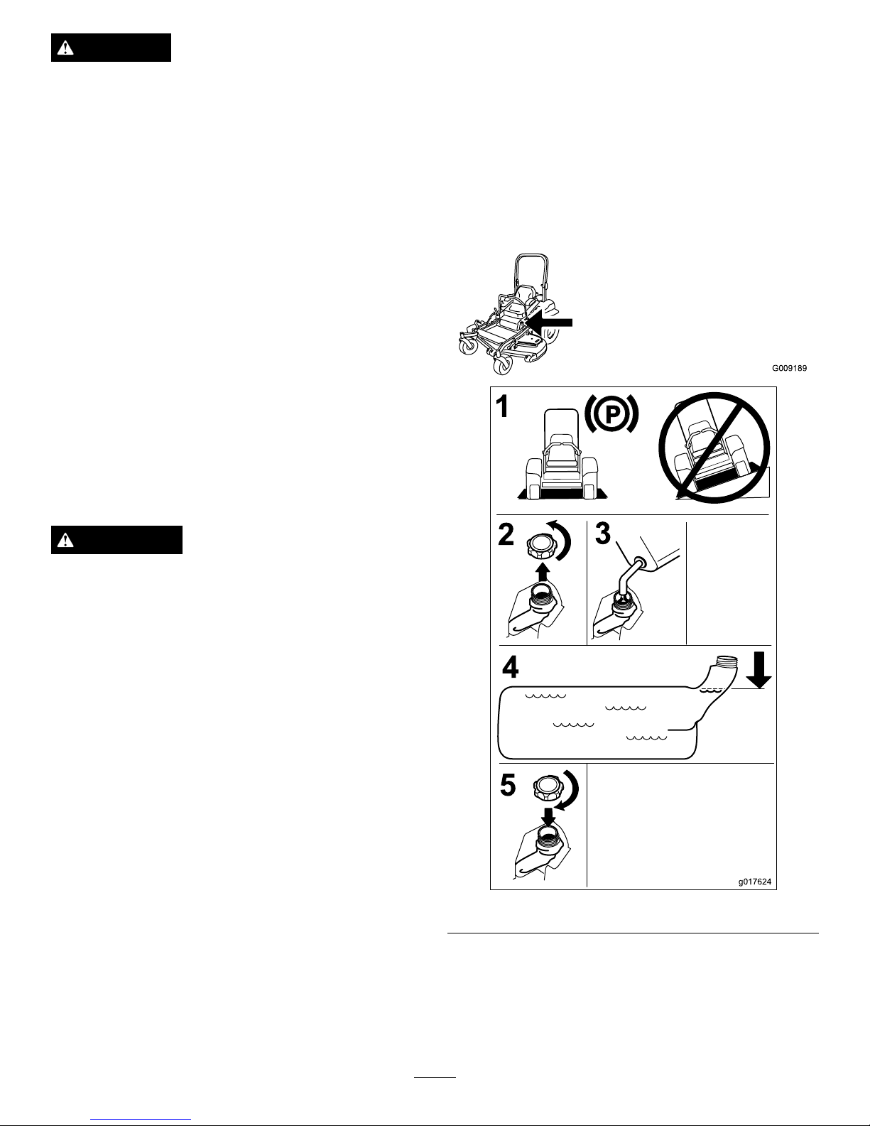
FillingtheFuelTank
Note:Donotllthefueltankcompletelyfull.Fillthefuel
tanktothebottomofthellerneck.Theemptyspaceinthe
tankallowsthegasolinetoexpand.
1.Parkthemachineonlevelground.
2.Shuttheengineoffandsettheparkingbrake.
3.Cleanaroundthefueltankcap.
4.Fillthefueltanktothebottomofthellerneck.
Ensurethereisemptyspaceinthetanktoallowthe
gasolinetoexpand(
Figure6).
G009189
g017624
1
2
4
3
5
Figure6
CheckingtheEngineOilLevel
Beforeyoustarttheengineandusethemachine,checktheoil
levelintheenginecrankcase;refertoCheckingtheEngine
OilLevel.
14
Page 15
BreakingInaNewMachine
Newenginestaketimetodevelopfullpower.Mowerdecks
anddrivesystemshavehigherfrictionwhennew ,placing
additionalloadontheengine.Allow40to50hoursof
break-intimefornewmachinestodevelopfullpowerand
bestperformance.
UsingtheRolloverProtection
System(ROPS)
WARNING
Toavoidinjuryordeathfromrollover:keeptheroll
barinthefullyraisedlockedpositionandusethe
seatbelt.
Ensuretheseatissecuredtothemachine.
WARNING
Thereisnorolloverprotectionwhentherollbaris
inthedownposition.
•Lowertherollbaronlywhenabsolutely
necessary.
•Donotweartheseatbeltwhentherollbaris
inthedownposition.
•Driveslowlyandcarefully.
•Raisetherollbarassoonasclearancepermits
andusetheseatbelt.
•Checkcarefullyforoverheadclearances(i.e.
branches,doorways,electricalwires)before
drivingunderanyobjectsanddonotcontact
them.
Important:Lowertherollbaronlywhenabsolutely
necessary.
Important:Ensuretheseatissecuredtothemachine.
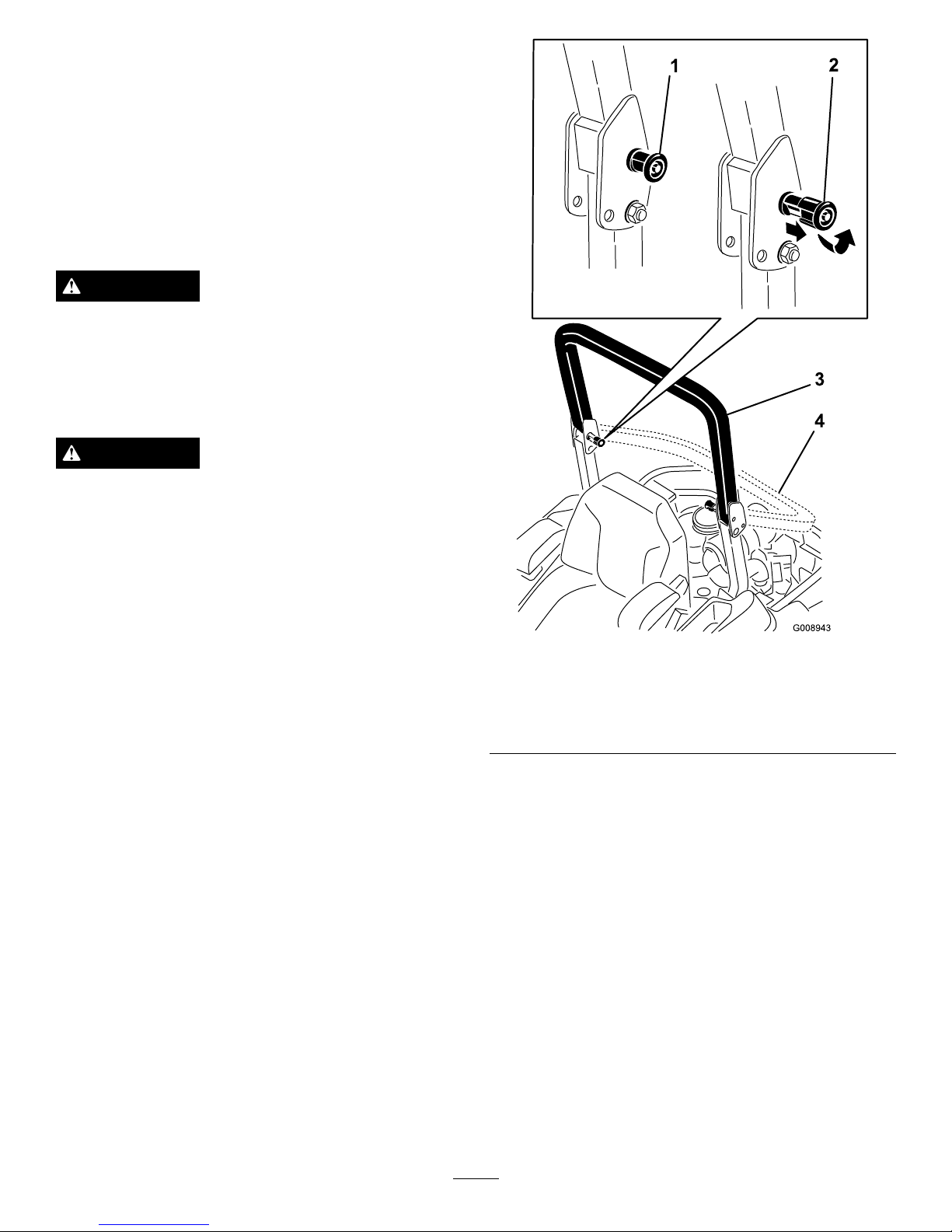
1.Tolowertherollbar,applyforwardpressuretothe
upperpartoftherollbar.
2.Pullbothknobsoutandrotatethem90°sotheyare
notengaged(Figure7).
3.Lowertherollbartothedownposition(Figure7).
Figure7
1.ROPSknob
3.Rollbarintheupright
position
2.PullROPSknoboutand
rotate90degrees
4.Rollbarinthefolded
position
4.Toraisetherollbar,raisetherollbartotheoperate
position,rotatetheknobssotheymovepartiallyinto
thegrooves(Figure7).
5.Raisetherollbartothefulluprightpositionwhile
pushingontheupperrollbarandthepinswillsnap
intopositionwhentheholesalignwiththepins
(Figure7).Pushontherollbarandensurethatboth
pinsareengaged.
Important:Alwaysusetheseatbeltwiththeroll
barinthefullyraisedposition.
ThinkSafetyFirst
Pleasereadallsafetyinstructionsandsymbolsinthesafety
section.Knowingthisinformationcouldhelpyouor
bystandersavoidinjury.
15
Page 16
DANGER
Operatingonwetgrassorsteepslopescancause
slidingandlossofcontrol.
Wheelsdroppingoveredgescancauserollovers,
whichmayresultinseriousinjury,deathor
drowning.
Thereisnorolloverprotectionwhentherollbaris
down.
Alwayskeeptherollbarinthefullyraisedand
lockedpositionandusetheseatbelt.
Readandfollowtherolloverprotectioninstructions
andwarnings.
Toavoidlossofcontrolandpossibilityofrollover:
•Donotoperateneardrop-offsornearwater.
•Donotoperateonslopesgreaterthan15degrees.
•Reducespeedanduseextremecautionon
slopes.
•Avoidsuddenturnsorrapidspeedchanges.
Figure8
1.SafeZone-usethe
ZMasterhereonslopes
lessthan15degreesor
atareas.
3.Water
2.DangerZone-useawalk
behindmowerand/ora
handtrimmeronslopes
greaterthan15degrees,
neardrop-offsandwater.
CAUTION
Thismachineproducessoundlevelsinexcessof
85dBAattheoperatorsearandcancausehearing
lossthroughextendedperiodsofexposure.
Wearhearingprotectionwhenoperatingthis
machine.
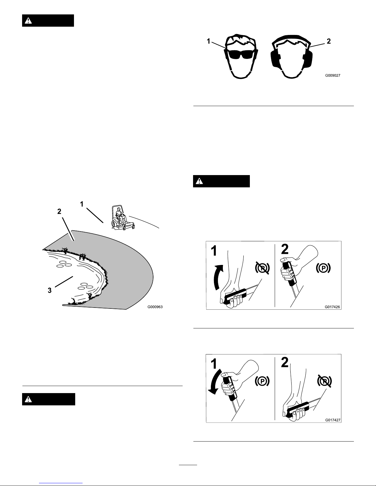
Theuseofprotectiveequipmentforeyes,ears,feetandhead
isrecommended.
G009027
1
2
Figure9
1.Wearsafetyglasses
2.Wearhearingprotection
OperatingtheParkingBrake
Alwayssettheparkingbrakewhenyoustopthemachineor
leaveitunattended.
SettingtheParkingBrake
WARNING
Parkingbrakemaynotholdmachineparkedona
slopeandcouldcausepersonalinjuryorproperty
damage.
Donotparkonslopesunlesswheelsarechocked
orblocked
G017426
1
2
Figure10
ReleasingtheParkingBrake
G017427
1
2
Figure11
16
Page 17
OperatingtheMowerBlade
ControlSwitch(PTO)
Thebladecontrolswitch(PTO)startsandstopsthemower
bladesandanypoweredattachments.
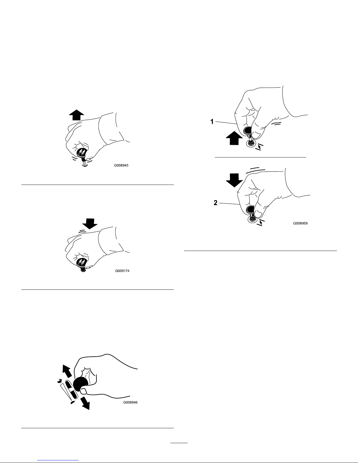
EngagingtheBladeControlSwitch
(PTO)
Note:Engagingthebladecontrolswitch(PTO)withthe
throttlepositionathalforlesswillcauseexcessivewearto
thedrivebelts.
G008945
Figure12
DisengagingtheBladeControlSwitch
(PTO)
G009174
Figure13
OperatingtheThrottle
ThethrottlecontrolcanbemovedbetweenFastandSlow
positions(Figure14).
Alwaysusethefastpositionwhenturningonthemowerdeck
withthebladecontrolswitch(PTO).
G008946
Figure14
OperatingtheChoke
Usethechoketostartacoldengine.
1.Iftheengineiscold,usethechoketostarttheengine.
2.Pulluponthechokeknobtoengagethechokebefore
usingtheignitionswitch(
Figure15).
3.Pushdownonthechoketodisengagethechokeafter
theenginehasstarted(Figure15).
G008959
1
2
Figure15
1.On2.Off
OperatingtheIgnitionSwitch
1.TurntheignitionkeytotheStartposition(Figure16).
Whentheenginesstarts,releasethekey.
Important:Donotengagestarterformorethan5
secondsatatime.Iftheenginefailstostartallow
a15secondcool-downperiodbetweenattempts.
Failuretofollowtheseinstructionscanburnout
thestartermotor.
Note:Additionalstartingcyclesmayberequired
whenstartingtheengineforthersttimeafterthefuel
systemhasbeenwithoutfuelcompletely.
17
Page 18
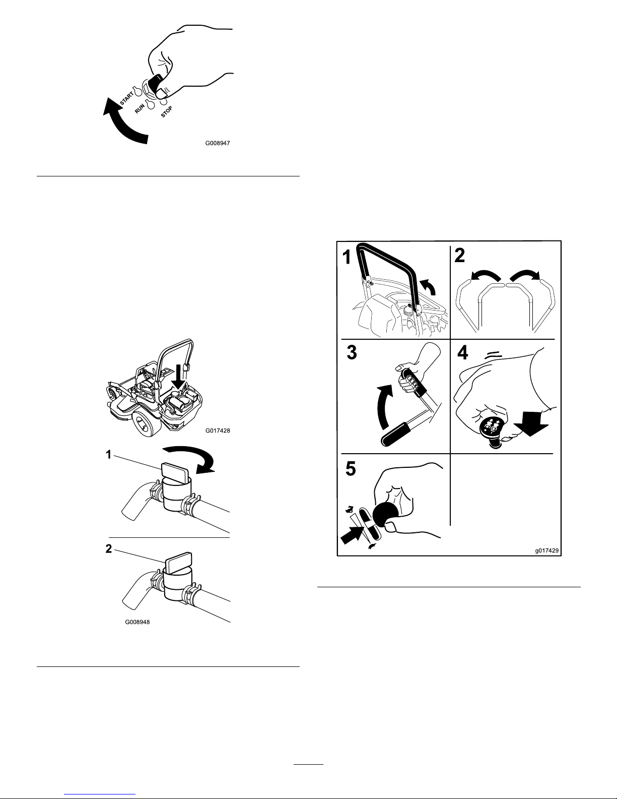
START
RUN
STOP
G008947
Figure16
2.Turntheignitionkeytothestoppositiontostopthe
engine.
UsingtheFuelShut-OffValve
Thefuelshut-offvalveislocatedbehindtheseat.
Closethefuelshut-offvalvefortransport,maintenance,and
storage.
Ensurethefuelshut-offvalveisopenwhenstartingthe
engine.
G017428
G008948
1
2
Figure17
1.On2.Off
StartingandStoppingthe
Engine
StartingtheEngine
1.RaisetheROPSupandlockintoplace,sitontheseat
andfastentheseatbelt.
2.Movethemotioncontrolstoneutrallockedposition.
3.Settheparkingbrake;refertoSettingtheParking
Brake.
4.Movethebladecontrolswitch(PTO)totheOff
position(Figure18).
5.MovethethrottlelevermidwaybetweentheSlowand
Fastpositions.
g017429
Figure18
6.TurntheignitionkeytotheStartposition(Figure16).
Whentheenginesstarts,releasethekey.
Important:Donotengagestarterformorethan5
secondsatatime.Iftheenginefailstostartallow
a15secondcool-downperiodbetweenattempts.
Failuretofollowtheseinstructionscanburnout
thestartermotor.
Note:Additionalstartingcyclesmayberequired
whenstartingtheengineforthersttimeafterthefuel
systemhasbeenwithoutfuelcompletely.
18
Page 19

START
RUN
STOP
G008947
Figure19
1.Off3.Start
2.Run
StoppingtheEngine
CAUTION
Childrenorbystandersmaybeinjuredifthey
moveorattempttooperatethemachinewhileitis
unattended.
Alwaysremovetheignitionkeyandsettheparking
brakewhenleavingthemachineunattended,even
ifjustforafewminutes.
Lettheengineidleatslowthrottle(turtle)for60seconds
beforeturningtheignitionswitchoff.
g017430
Figure20
Important:Makesurethatthefuelshutoffvalveis
closedbeforetransportingorstoringthemachine,as
fuelleakagemayoccur.Settheparkingbrakebefore
transporting.Makesuretoremovethekeyasthefuel
pumpmayrunandcausethebatterytolosecharge.
TheSafetyInterlockSystem
CAUTION
Ifsafetyinterlockswitchesaredisconnectedor
damagedthemachinecouldoperateunexpectedly
causingpersonalinjury.
•Donottamperwiththeinterlockswitches.
•Checktheoperationoftheinterlockswitches
dailyandreplaceanydamagedswitchesbefore
operatingthemachine.
19
Page 20

UnderstandingtheSafetyInterlock
System
Thesafetyinterlocksystemisdesignedtopreventtheengine
fromstartingunless:
•Theparkingbrakeisengaged.
•Thebladecontrolswitch(PTO)isdisengaged.
•Themotioncontrolleversareintheneutrallocked
position
Thesafetyinterlocksystemalsoisdesignedtostopthe
enginewhenthetractioncontrolsaremovedfromthelocked
positionwiththeparkingbrakeengagedorifyourisefrom
theseatwhenthePTOisengaged.
TestingtheSafetyInterlockSystem
ServiceInterval:Beforeeachuseordaily
Testthesafetyinterlocksystembeforeyouusethemachine
eachtime.Ifthesafetysystemdoesnotoperateasdescribed
below,haveanAuthorizedServiceDealerrepairthesafety
systemimmediately.
1.Sittingontheseat,engagetheparkingbrakeandmove
thebladecontrolswitch(PTO)toon.Trystartingthe
engine;theengineshouldnotcrank.
2.Sittingontheseat,engagetheparkingbrakeandmove
thebladecontrolswitch(PTO)tooff.Moveeither
motioncontrollever(outofneutrallockedposition).
Trystartingtheengine;theengineshouldnotcrank.
Repeatforothercontrollever.
3.Sittingontheseat,engagetheparkingbrake,movethe
bladecontrolswitch(PTO)tooffandmovethemotion
controlleverstoneutrallockposition.Nowstartthe
engine.Whiletheengineisrunning,releasetheparking
brake,engagethebladecontrolswitch(PTO)andrise
slightlyfromtheseat;theengineshouldstop.
4.Sittingontheseat,engagetheparkingbrake,movethe
bladecontrolswitch(PTO)tooffandmovethemotion
controlleverstoneutrallockposition.Nowstartthe
engine.Whiletheengineisrunning,centereither
motioncontrolandmove(forwardorreverse);the
engineshouldstop.Repeatforothermotioncontrol.
5.Sittingontheseat,disengagetheparkingbrake,move
thebladecontrolswitch(PTO)tooffandmovethe
motioncontrolleverstoneutrallockposition.Try
startingtheengine;theengineshouldnotcrank.
DrivingForwardorBackward
Thethrottlecontrolregulatestheenginespeedasmeasured
inrpm(revolutionsperminute).Placethethrottlecontrolin
thefastpositionforbestperformance.Alwaysoperateinthe
fullthrottlepositionwhenmowing.
CAUTION
Machinecanspinveryrapidly.Operatormaylose
controlofmachineandcausepersonalinjuryor
damagetomachine.
•Usecautionwhenmakingturns.
•Slowthemachinedownbeforemakingsharp
turns.
UsingtheMotionControlLevers
Figure21
1.Motioncontrol
lever-neutrallockposition
4.Backward
2.Center,unlockedposition5.Frontofmachine
3.Forward
DrivingForward
Note:Theenginewillkillifthetractioncontrolleversare
movedwiththeparkingbrakeengaged.
Tostop,pullthemotioncontrolleverstotheneutralposition.
1.Releasetheparkingbrake;refertoReleasingthe
ParkingBrakeinOperation.
2.Movetheleverstothecenter,unlockedposition.
3.Togoforward,slowlypushthemotioncontrollevers
forward(
Figure22).
20
Page 21

G008952
Figure22
DrivingBackward
1.Movetheleverstothecenter,unlockedposition.
2.Togobackward,slowlypullthemotioncontrollevers
rearward(Figure23).
G008953
Figure23
StoppingtheMachine
Tostopthemachine,movethetractioncontrolleversto
neutralandmovetolockedposition,disengagethepower
takeoff(bladecontrolswitch(PTO),andturntheignition
keytooff.
Settheparkingbrakewhenyouleavethemachine;referto
SettingtheParkingBrakeinOperation.Remembertoremove
thekeyfromtheignitionswitch.
CAUTION
Childrenorbystandersmaybeinjuredifthey
moveorattempttooperatethemachinewhileitis
unattended.
Alwaysremovetheignitionkeyandsettheparking
brakewhenleavingthemachineunattended,even
ifjustforafewminutes.
AdjustingtheHeightofCut
UsingtheTransportLock
Thetransportlockhastwopositionsandisusedwiththe
deckliftpedal.Thereisalockpositionandaunlockposition
forthetransportposition.Thetransportlockisusedwiththe
deckliftpedal.RefertoFigure24.
21
Page 22

Figure24
TransportLockPositions
1.Transportlock3.Unlockposition—doesnot
lockthemowerdeckinto
transportposition
2.Lockposition—mower
deckwilllockintotransport
position
AdjustingtheHeight-of-CutPin
Mowerdecksize
Height-of-cut
range
Increments
48inch
1-1/2to5inches
(38to127mm)
1/4inch(6mm)
Theheight-of-cutisadjustedbyrelocatingtheclevispininto
differentholelocations.
1.Movethetransportlocktothelockposition.
2.Pushonthedeckliftpedalwithyourfootandraisethe
mowerdecktothetransportposition(alsothe5-1/2
inch(140mm)cuttingheightposition)(
Figure25).
3.Toadjust,rotatethepin90degreesandremovethepin
fromtheheight-of-cutbracket(Figure25).
4.Selectaholeintheheight-of-cutbracketcorresponding
totheheight-of-cutdesiredand,insertthepin
(Figure25).
5.Pushonthedecklift,pullbackonthetransportlock,
andslowlylowerthemowerdeck.
g017419
2
1
3
Figure25
1.Deckliftpedal
3.Transportlock
2.Cutofheightpin
AdjustingtheAnti-Scalp
Rollers
Wheneveryouchangetheheight-of-cut,itisrecommended
toadjusttheheightoftheanti-scalprollers.
1.Disengagethebladecontrolswitch(PTO),movethe
motioncontrolleverstotheneutrallockedposition
andsettheparkingbrake.
2.Stoptheengine,removethekey,andwaitforallmoving
partstostopbeforeleavingtheoperatingposition.
22
Page 23

g017628
Figure26
1.Anti-scalproller4.FlangeNut
2.Spacer
5.Bolt
3.Bushing
g017629
Figure27
1.Anti-scalproller3.FlangeNut
2.Bushing4.Bolt
PositioningtheSeat
Theseatcanmoveforwardandbackward.Positiontheseat
whereyouhavethebestcontrolofthemachineandaremost
comfortable.
Toadjust,movetheleversidewaystounlockseat(Figure28).
G008962
Figure28
UsingtheDriveWheelRelease
Valves
WARNING
Handsmaybecomeentangledintherotatingdrive
componentsbelowtheenginedeck,whichcould
resultinseriousinjury.
Stoptheengine,removethekey,andallowall
movingpartstostopbeforeaccessingthedrive
wheelreleasevalves.
WARNING
Theengineandhydraulicdriveunitscanbecome
veryhot.Touchingahotengineorhydraulicdrive
unitscancausesevereburns.
Allowtheengineandhydraulicdriveunitstocool
completelybeforeaccessingthedrivewheelrelease
valves.
Thedrivewheelreleasevalvesarelocatedbehindtheseatand
downintheenginecompartment.
1.DisengagethePTO(bladecontrolswitch)andturnthe
ignitionkeytooff.Movetheleverstoneutrallocked
positionandapplyparkingbrake.Removethekey.
2.Locatethebypassleversbehindtheseat,downonthe
leftandrightsideoftheframe.
3.Topushthemachine,movethebypassleversrearward
andouttolocktheminplaceasshownin
Figure29.
Repeatthisoneachsideofthemachine.
4.Disengageparkingbrakebeforepushing.
g017420
2
3
4
1
Figure29
23
Page 24

5.Torunthemachine,movethebypassleverstothe
forwardposition(Figure29).
UsingtheSideDischarge
Themowerhasahingedgrassdeectorthatdisperses
clippingstothesideanddowntowardtheturf.
DANGER
Withoutagrassdeector,dischargecover,or
completegrasscatcherassemblymountedin
place,youandothersareexposedtobladecontact
andthrowndebris.Contactwithrotatingmower
blade(s)andthrowndebriswillcauseinjuryor
death.
•Neverremovethegrassdeectorfromthemower
becausethegrassdeectorroutesmaterialdown
towardtheturf.Ifthegrassdeectorisever
damaged,replaceitimmediately .
•Neverputyourhandsorfeetunderthemower.
•Nevertrytoclearthedischargeareaormower
bladesunlessyoumovethepowertakeoff(blade
controlswitch(PTO)totheoffposition,rotate
theignitionkeytooffandremovethekey.
•Makesurethegrassdeectorisinthedown
position.
LoadingMachines
Useextremecautionwhenloadingunitsontrailersortrucks.
Onefullwidthrampthatiswideenoughtoextendbeyond
thereartiresisrecommendedinsteadofindividualrampsfor
eachsideoftheunit(Figure30).Thelowerrearsectionof
themachineframeextendsbackbetweentherearwheelsand
servesasastopfortippingbackward.Havingafullwidth
rampprovidesasurfacefortheframememberstocontactif
theunitstartstotipbackward.Ifitisnotpossibletouseone
fullwidthramp,useenoughindividualrampstosimulatea
fullwidthcontinuousramp.
Therampshouldbelongenoughsothattheanglesdonot
exceed15degrees(
Figure30).Asteeperanglemaycause
mowercomponentstogetcaughtastheunitmovesfrom
ramptotrailerortruck.Steeperanglesmayalsocausethe
unittotipbackward.Ifloadingonornearaslope,position
thetrailerortrucksoitisonthedownsideoftheslopeand
therampextendsuptheslope.Thiswillminimizetheramp
angle.Thetrailerortruckshouldbeaslevelaspossible.
Important:DoNotattempttoturntheunitwhileon
theramp;youmaylosecontrolanddriveofftheside.
Avoidsuddenaccelerationwhendrivinguparampand
suddendecelerationwhenbackingdownaramp.Both
maneuverscancausetheunittotipbackward.
WARNING
Loadingaunitontoatrailerortruckincreasesthe
possibilityofbackwardtip-overandcouldcause
seriousinjuryordeath.
•Useextremecautionwhenoperatingauniton
aramp.
•EnsuretheROPSisintheuppositionwhile
usingtheseatbeltwhenloadingthemachine.
EnsuretheROPSwillclearthetopofan
enclosedtrailer.
•Useonlyasingle,fullwidthramp;DoNotuse
individualrampsforeachsideoftheunit.
•Ifindividualrampsmustbeused,useenough
rampstocreateanunbrokenrampsurfacewider
thantheunit.
•Donotexceeda15degreeanglebetweenramp
andgroundorbetweenrampandtrailerortruck.
•Avoidsuddenaccelerationwhiledrivingunitup
aramptoavoidtippingbackward.
•Avoidsuddendecelerationwhilebackingunit
downaramptoavoidtippingbackward.
Figure30
1.Trailer3.Notgreaterthan
15degrees
2.Fullwidthramp4.Fullwidthramp—sideview
24
Page 25

TransportingMachines
Useaheavy-dutytrailerortrucktotransportthemachine.
Ensurethatthetrailerortruckhasallnecessarybrakes,
lighting,andmarkingasrequiredbylaw.Pleasecarefullyread
allthesafetyinstructions.Knowingthisinformationcould
helpyou,yourfamily,petsorbystandersavoidinjury.
WARNING
Drivingonthestreetorroadwaywithoutturn
signals,lights,reectivemarkings,oraslow
movingvehicleemblemisdangerousandcanlead
toaccidentscausingpersonalinjury.
Donotdrivemachineonapublicstreetorroadway.
Totransportthemachine:
1.Ifusingatrailer,connectittothetowingvehicleand
connectthesafetychains.
2.Ifapplicable,connectthetrailerbrakes.
3.Loadthemachineontothetrailerortruck.
4.Stoptheengine,removethekey,setthebrake,and
closethefuelvalve.
5.Usethemetaltiedownloopsonthemachineto
securelyfastenthemachinetothetrailerortruckwith
straps,chains,cable,orropes(
Figure31).
Figure31
1.Tractionunittiedownloops
25
Page 26

OperatingTips
FastThrottleSetting
Forbestmowingandmaximumaircirculation,operate
theengineatthefastthrottleposition.Airisrequiredto
thoroughlycutgrassclippings,sodonotsettheheight-of-cut
solowastototallysurroundthemowerbyuncutgrass.
Alwaystrytohaveonesideofthemowerfreefromuncut
grass,whichallowsairtobedrawnintothemower.
CuttingaLawnfortheFirstTime
Cutgrassslightlylongerthannormaltoensurethecutting
heightofthemowerdoesnotscalpanyunevenground.
However,thecuttingheightusedinthepastisgenerallythe
bestonetouse.Whencuttinggrasslongerthansixinchestall,
youmaywanttocutthelawntwicetoensureanacceptable
qualityofcut.
Cut1/3oftheGrassBlade
Itisbesttocutonlyabout1/3ofthegrassblade.Cutting
morethanthatisnotrecommendedunlessgrassissparse,or
itislatefallwhengrassgrowsmoreslowly.
MowingDirection
Alternatemowingdirectiontokeepthegrassstanding
straight.Thisalsohelpsdisperseclippingswhichenhances
decompositionandfertilization.
MowatCorrectIntervals
Normally,moweveryfourdays.Butremember,grassgrows
atdifferentratesatdifferenttimes.Sotomaintainthesame
cuttingheight,whichisagoodpractice,mowmoreoftenin
earlyspring.Asthegrassgrowthrateslowsinmidsummer,
mowlessfrequently .Ifyoucannotmowforanextended
period,rstmowatahighcuttingheight;thenmowagain
twodayslateratalowerheightsetting.
CuttingSpeed
Toimprovecutquality ,useaslowergroundspeedincertain
conditions.
AvoidCuttingTooLow
Ifthecuttingwidthofthemoweriswiderthanthemower
youpreviouslyused,raisethecuttingheighttoensurethat
uneventurfisnotcuttooshort.
LongGrass
Ifthegrassiseverallowedtogrowslightlylongerthan
normal,orifitcontainsahighdegreeofmoisture,raisethe
cuttingheighthigherthanusualandcutthegrassatthis
setting.Thencutthegrassagainusingthelower,normal
setting.
WhenStopping
Ifthemachine'sforwardmotionmustbestoppedwhile
mowing,aclumpofgrassclippingsmaydropontoyourlawn.
Toavoidthis,moveontoapreviouslycutareawiththeblades
engaged.
KeeptheUndersideoftheMowerClean
Cleanclippingsanddirtfromtheundersideofthemower
aftereachuse.Ifgrassanddirtbuildupinsidethemower,
cuttingqualitywilleventuallybecomeunsatisfactory.
BladeMaintenance
Maintainasharpbladethroughoutthecuttingseasonbecause
asharpbladecutscleanlywithouttearingorshreddingthe
grassblades.Tearingandshreddingturnsgrassbrownat
theedges,whichslowsgrowthandincreasesthechanceof
disease.Checkthecutterbladesdailyforsharpness,andfor
anywearordamage.Filedownanynicksandsharpenthe
bladesasnecessary.Ifabladeisdamagedorworn,replaceit
immediatelywithagenuineTOROreplacementblade.
26
Page 27

Maintenance
RecommendedMaintenanceSchedule(s)
MaintenanceService
Interval
MaintenanceProcedure
Aftertherst8hours
•Changetheengineoil.
Aftertherst50hours
•Changethehydraulicsystemlterandoil.
Beforeeachuseordaily
•Checkthesafetysystem.
•Checktheengineoillevel.
•Checktheseatbelt.
•Checktherolloverprotectionsystem(ROPS)knobs.
•Cleantheenginescreen.
•Checkthemowerblades.
•Cleanthemowerdeck.
Every25hours
•Checkthehydraulicoillevelintheexpansiontank.
Every50hours
•Greasethemowerdeckidlerarm.
•Checksparkarrester(ifequipped).
•Checkthetirepressure.
•Inspectthebeltsforcracksandwear.
Every100hours
•Lubricatethemowerdeckliftpivots.
•Changetheengineoil(moreoftenindirtyordustyconditions).
•Check,cleanandregapthesparkplug.
•Checkandcleanenginecoolingnsandshrouds.
Every200hours
•Changetheengineoillter.
Every250hours
•Replacetheprimaryairlter.
•Checkthesecondaryairlter.
Every400hours
•Changethehydraulicsystemlterandoil.
Every500hours
•Replacethesecondaryairlter.
•Replacethefuellter(moreoftenindirtyordustyconditions).
•Adjustthecasterpivotbearing.
•Checktheelectricclutch.
Monthly
•Checkthebattery .
Yearly
•Greasethefrontcasterpivots(moreoftenindirtyordustyconditions).
•Lubricatethecasterwheelhubs.
Yearlyorbeforestorage
•Paintchippedsurfaces.
•Checkallmaintenanceprocedureslistedabovebeforestorage.
Important:Refertoyourengineoperator'smanualforadditionalmaintenanceprocedures.
CAUTION
Ifyouleavethekeyintheignitionswitch,someonecouldaccidentlystarttheengineandseriouslyinjure
youorotherbystanders.
Removethekeyfromtheignitionbeforeyoudoanymaintenance.
27
Page 28

Lubrication
GreasingandLubrication
Greasemorefrequentlywhenoperatingconditionsare
extremelydustyorsandy .
GreaseType:No.2generalpurposelithiumbaseor
molybdenumbasegrease
HowtoGrease
1.Disengagethebladecontrolswitch(PTO),movethe
motioncontrolleverstotheneutrallockedposition
andsettheparkingbrake.
2.Stoptheengine,removethekey,andwaitforallmoving
partstostopbeforeleavingtheoperatingposition.
3.Cleanthegreasettingswitharag.Makesuretoscrape
anypaintoffthefrontofthetting(s).
4.Connectagreaseguntothetting.Pumpgrease
intothettingsuntilgreasebeginstooozeoutofthe
bearings.
5.Wipeupanyexcessgrease.
WheretoAddLightOilorSpray
Lubrication
ServiceInterval:Every100hours
Lubricatethedeckliftpivots.
g017421
Figure32
WheretoGreasetheMower
ServiceInterval:Every50hours—Greasethemowerdeck
idlerarm.
Yearly—Greasethefrontcasterpivots(moreoftenin
dirtyordustyconditions).
1.Disengagethebladecontrolswitch(PTO),movethe
motioncontrolleverstotheneutrallockedposition,
andsettheparkingbrake.
2.Stoptheengine,removethekey,andwaitforallmoving
partstostopbeforeleavingtheoperatingposition.
3.Greasethemowerdeckidlerpulleypivotuntilgrease
comeoutthebottom(Figure33).
g017435
Figure33
4.Removethedustcapandadjustthecasterpivots.
Keepthedustcapoffuntilgreasingisdone.Referto
AdjustingtheCasterPivotBearinginMaintenance.
5.Removethehexplug.Threadagreasezerkintothe
hole.
6.Pumpgreaseintothezerkuntilitoozesoutaround
thetopbearing.
7.Removethegreasezerkinthehole.Installthehexplug
anddustcap(
Figure34).
g014942
Figure34
28
Page 29

LubricatetheCasterWheel
Hubs
ServiceInterval:Yearly
1.Stoptheengine,waitforallmovingpartstostop,and
removethekey .Engagetheparkingbrake.
Figure35
1.Sealguard2.Spacernutwithwrench
ats
2.Raisethefrontofthemachineupandsupportitwith
jackstands.
3.Removethecasterwheelfromthecasterforks.
4.Removethesealguardsfromthewheelhub.
5.Remove1ofthespacernutsfromtheaxleassemblyin
thecasterwheel.Notethatthreadlockingadhesive
hasbeenappliedtolockthespacernutstotheaxle.
Removetheaxle(withtheotherspacernutstill
assembledtoit)fromthewheelassembly.
6.Pryouttheseals,andinspectthebearingsforwearor
damageandreplaceifnecessary.
7.Packthebearingswithageneral-purposegrease.
8.Insert1bearingand1newsealintothewheel.
Note:Thesealsmustbereplaced.
9.Iftheaxleassemblyhashadbothspacernutsremoved
(orbrokenloose),applyathreadlockingadhesiveto1
spacernutandthreaditontotheaxlewiththewrench
atsfacingoutward.Donotthreadthespacernutallof
thewayontotheendoftheaxle.Leaveapproximately
3mm(1/8inch)fromtheoutersurfaceofthespacer
nuttotheendoftheaxleinsidethenut.
10.Inserttheassemblednutandaxleintothewheelonthe
sideofthewheelwiththenewsealandbearing.
11.Withtheopenendofthewheelfacingup,llthearea
insidethewheelaroundtheaxlefullofgeneral-purpose
grease.
12.Insertthesecondbearingandnewsealintothewheel.
13.Applyathreadlockingadhesivetothesecondspacer
nutandthreaditontotheaxlewiththewrenchats
facingoutward.
14.Torquethenutto8-9N-m(75-80in-lb),loosen,then
re-torqueto2-3N-m(20-25in-lb).Makesurethatthe
axledoesnotextendbeyondeithernut.
15.Installthesealguardsoverthewheelhubandinsert
thewheelintothecasterfork.Installthecasterbolt
andtightenthenutfully.
Important:T opreventsealandbearingdamage,check
thebearingadjustmentoften.Spinthecastertire.The
tireshouldnotspinfreely(morethan1or2revolutions)
orhaveanysideplay.Ifthewheelspinsfreely,adjustthe
torqueonthespacernutuntilthereisaslightamountof
drag.Applythreadlockingadhesive.
16.Raisethefrontofthemachineupandremovethejack
stands.
29
Page 30

EngineMaintenance
WARNING
Contactwithhotsurfacesmaycausepersonal
injury.
Keephands,feet,face,clothingandotherbody
partsawaythemuferandotherhotsurfaces.
ServicingtheAirCleaner
ServiceInterval:Every250hours—Replacetheprimaryair
lter.
Every250hours—Checkthesecondaryairlter.
Every500hours—Replacethesecondaryairlter.
Note:Servicetheaircleanermorefrequentlyifoperating
conditionsareextremelydustyorsandy.
RemovingtheFilters
1.DisengagethePTO ,movethemotioncontrolleversto
theneutrallockedpositionandsettheparkingbrake.
2.Stoptheengine,removethekey,andwaitforallmoving
partstostopbeforeleavingtheoperatingposition.
3.Pushdowntoreleasetheretainingclampsontheair
cleanerandpulltheaircleanercoveroffoftheair
cleanerbody(
Figure36).
4.Cleantheinsideoftheaircleanercoverwith
compressedair.
5.Gentlyslidetheprimarylteroutoftheaircleaner
body(Figure36).Avoidknockingthelterintothe
sideofthebody.
6.Removethesecondarylteronlyifyouintendto
replaceit.
Important:Neverattempttocleanthesecondary
lter.Ifthesecondarylterisdirty,thenthe
primarylterisdamagedandyoushouldreplace
bothlters.
7.Inspecttheprimarylterfordamagebylookinginto
thelterwhileshiningabrightlightontheoutsideof
thelter.Holesinthelterwillappearasbrightspots.
Ifthelterisdamageddiscardit.
Figure36
1.Aircleanerclamps
3.Primaryairlter
2.Aircleanercover
4.Secondaryairlter
ServicingthePrimaryFilter
1.Donotcleanthepaperlter,replaceit(Figure36).
2.Inspecttheelementfortears,anoilylm,ordamageto
therubberseal.
3.Replacethepaperelementifitisdamaged.
ServicingtheSecondaryFilter
Donotcleanthesecondarylter,replaceit.
Important:Neverattempttocleanthesecondarylter.
Ifthesecondarylterisdirty,thentheprimarylteris
damagedandyoushouldreplacebothlters.
InstallingtheFilters
Important:T opreventenginedamage,alwaysoperate
theenginewithbothairltersandcoverinstalled.
1.Ifinstallingnewlters,checkeachlterforshipping
damage.Donotuseadamagedlter.
2.Ifthesecondarylterisbeingreplaced,carefullyslide
itintothelterbody(Figure36).
3.Carefullyslidetheprimarylteroverthesecondary
lter(Figure36).Ensurethatitisfullyseatedby
pushingontheouterrimofthelterwhileinstallingit.
Important:Donotpressonthesoftinsidearea
ofthelter.
4.Installtheaircleanercoverwiththebreathercapdown
androtatesotheretainingclampslockthecoverin
place(
Figure36).
30
Page 31

ServicingtheEngineOil
OilType:Detergentoil(APIserviceSF ,SG,SH,SJ,orSL)
CrankcaseCapacity:withalterchange,71ounces(2.1L);
withoutalterchange,61ounces(1.8L)
Viscosity:Seethetablebelow.
Figure37
Note:Useofmulti-gradeoils(5W-20,10W -30,or10W-40)
willincreaseoilconsumption.Checktheoillevelmore
frequentlywhenusingthem.
CheckingtheEngineOilLevel
ServiceInterval:Beforeeachuseordaily
Note:Checktheoilwhentheengineiscold.
WARNING
Contactwithhotsurfacesmaycausepersonal
injury.
Keephands,feet,face,clothingandotherbody
partsawayfromthemuferandotherhotsurfaces.
Important:Donotoverllthecrankcasewithoil
becausedamagetotheenginemayresult.Donotrun
enginewithoilbelowthelowmarkbecausetheengine
maybedamaged.
1.DisengagethePTO ,movethemotioncontrolleversto
theneutrallockedpositionandsettheparkingbrake.
2.Stoptheengine,removethekey ,andwaitforall
movingpartstostopbeforeleavingtheoperating
position(
Figure38).
G008804
G008792
1
2
5
6
7
3
9
10
4
8
Figure38
31
Page 32

ChangingtheEngineOil
ServiceInterval:Aftertherst8hours
Every100hours(moreoftenindirtyordusty
conditions).
Note:Disposeoftheusedoilatarecyclingcenter.
1.Parkthemachinesothattherearisslightlylowerthan
thefronttoensuretheoildrainscompletely .
2.DisengagethePTO ,movethemotioncontrolleversto
theneutrallockedpositionandsettheparkingbrake.
3.Stoptheengine,removethekey,andwaitforallmoving
partstostopbeforeleavingtheoperatingposition.
4.Changetheengineoil(
Figure39).
G008804
G008793
1
2
3
4
4
5
Figure39
5.Slowlypourapproximately80%ofthespeciedoil
intothellertubeandslowlyaddtheadditionaloilto
bringittotheFullmark(Figure40).
G008796
2
3
4
5
6
1
Figure40
6.Starttheengineanddrivetoaatarea.Checktheoil
levelagain.
ChangingtheEngineOilFilter
ServiceInterval:Every200hours
Note:Changetheengineoilltermorefrequentlywhen
operatingconditionsareextremelydustyorsandy.
1.Draintheoilfromtheengine;refertoChangingthe
EngineOil.
2.Changetheengineoillter(Figure41).
32
Page 33

G017452
G008748
3/4
1
2
3
4
5
6
Figure41
Note:Ensuretheoilltergaskettouchestheengine
andthenanextra3/4turniscompleted.
3.Fillthecrankcasewiththepropertypeofnewoil;refer
toChangingtheOil.
ServicingtheSparkPlug
ServiceInterval:Every100hours
Makesuretheairgapbetweenthecenterandsideelectrodes
iscorrectbeforeinstallingthesparkplug.Useasparkplug
wrenchforremovingandinstallingthesparkplug(s)anda
gappingtool/feelergaugetocheckandadjusttheairgap.
Installanewsparkplug(s)ifnecessary.
TypeofSparkPlug:NGK
®
BPR4ESorequivalent
AirGap:0.030inch(0.75mm)
RemovingtheSparkPlug
1.Stoptheengine,removethekey,andwaitforallmoving
partstostopbeforeleavingtheoperatingposition.
2.DisengagethePTO ,movethemotioncontrolleversto
theneutrallockedpositionandsettheparkingbrake.
3.Locateandremovethesparkplugs(Figure42).
g015124
Figure42
CheckingtheSparkPlug
Important:Nevercleanthesparkplug(s).Always
replacethesparkplug(s)whenithas:ablackcoating,
wornelectrodes,anoilylm,orcracks.
Ifyouseelightbrownorgrayontheinsulator,theengineis
operatingproperly.Ablackcoatingontheinsulatorusually
meanstheaircleanerisdirty.
Setthegapto0.030inches(0.76mm).
G008794
1
2
Figure43
33
Page 34

InstallingtheSparkPlug
Tightenthesparkplug(s)to16ft.-lb(22N-m).
3
2
1
G015200
Figure44
CheckSparkArrester(if
equipped)
ServiceInterval:Every50hours
WARNING
Hotexhaustsystemcomponentsmayignite
gasolinevaporsevenaftertheengineisstopped.
Hotparticlesexhaustedduringengineoperation
mayigniteammablematerials.Firemayresultin
personalinjuryorpropertydamage.
DoNotrefuelorrunengineunlesssparkarrester
isinstalled.
1.Stopengine,waitforallmovingpartstostop,and
removekey.Engageparkingbrake.
2.Waitformufertocool.
3.Ifanybreaksinthescreenorweldsareobserved,
replacethearrester.
4.Ifpluggingofthescreenisobserved,removethe
arresterandshakelooseparticlesoutofthearrester
andcleanscreenwithawirebrush(soakinsolventif
necessary).Reinstallarresteronexhaustoutlet.
FuelSystem
Maintenance
ReplacingtheFuelFilter
ServiceInterval:Every500hours/Yearly(whichevercomes
rst)(moreoftenindirtyordusty
conditions).
Thefuellterislocatedneartheengineonthefrontorrear
sideoftheengine.
1.DisengagethePTO ,movethemotioncontrolleversto
theneutrallockedposition,andsettheparkingbrake.
2.Stoptheengine,removethekey,andwaitforallmoving
partstostopbeforeleavingtheoperatingposition.
3.Allowthemachinetocooldown.
4.Stoptheengine,removethekey,andwaitforallmoving
partstostopbeforeleavingtheoperatingposition.
5.Closethefuelshutoffvalvebehindtheseat(
Figure45).
G008963
12
3
Figure45
1.Fuellter
3.Fuelline
2.Hoseclamp
6.Squeezetheendsofthehoseclampstogetherandslide
themawayfromthelter(Figure45).
7.Removethelterfromthefuellines.
8.Installanewlterandmovethehoseclampscloseto
thelter(Figure45).
9.Openthefuelshutoffvalve.
Note:Itisimportanttoreinstallthefuellinehosesand
securewithplastictiesthesameastheywereoriginally
installedatthefactorytokeepthefuellineawayfrom
componentsthatcouldcausefuellinedamage.
34
Page 35

ServicingtheFuelTank
Donotattempttodrainthefueltank.Ensurethatan
AuthorizedServiceDealerdrainsthefueltankandservices
anycomponentsofthefuelsystem.
ElectricalSystem
Maintenance
ServicingtheBattery
ServiceInterval:Monthly
DANGER
Batteryelectrolytecontainssulfuricacidwhichisa
deadlypoisonandcausessevereburns.
Donotdrinkelectrolyteandavoidcontactwith
skin,eyesorclothing.Wearsafetyglassestoshield
youreyesandrubberglovestoprotectyourhands.
RemovingtheBattery
WARNING
Batteryterminalsormetaltoolscouldshortagainst
metalmachinecomponentscausingsparks.Sparks
cancausethebatterygassestoexplode,resulting
inpersonalinjury.
•Whenremovingorinstallingthebattery,donot
allowthebatteryterminalstotouchanymetal
partsofthemachine.
•Donotallowmetaltoolstoshortbetween
thebatteryterminalsandmetalpartsofthe
machine.
WARNING
Incorrectbatterycableroutingcoulddamagethe
machineandcablescausingsparks.Sparkscan
causethebatterygassestoexplode,resultingin
personalinjury.
•AlwaysDisconnectthenegative(black)battery
cablebeforedisconnectingthepositive(red)
cable.
•AlwaysReconnectthepositive(red)battery
cablebeforereconnectingthenegative(black)
cable.
1.Disengagethebladecontrolswitch(PTO),movethe
motioncontrolleverstotheneutrallockedposition
andsettheparkingbrake.
2.Stoptheengine,removethekey,andwaitforallmoving
partstostopbeforeleavingtheoperatingposition.
3.Firstdisconnectthenegativebatterycable(black)from
thenegative(-)(black)batteryterminal(
Figure46).
4.Slidetheredterminalbootoffthepositive(red)battery
terminalandremovethepositive(+)(red)batterycable
(Figure46).
35
Page 36

5.Removethewingnutsecuringthebatteryclamp
(Figure46).
6.Removetheclamp(Figure46).
7.Removethebattery.
g014731
+
-
+
-
+
-
1
2
3
4
Figure46
1.Removethewingnutand
clamp
3.Removethepositive
batterycable
2.Removethenegative
batterycablebeforethe
positive
4.Removebattery
InstallingtheBattery
1.Positionbatteryinthetraywiththeterminalposts
oppositefromthehydraulictank(Figure46).
2.First,installthepositive(red)batterycabletopositive
(+)batteryterminal.
3.Theninstallthenegative(black)batterycableand
groundwiretothenegative(-)batteryterminal.
4.Securethecableswith2bolts,2washers,and2locknuts
(
Figure46).
5.Slidetheredterminalbootontothepositive(red)
batterypost.
6.Installtheclampandsecureitwiththewingnut
(Figure46).
ChargingtheBattery
WARNING
Chargingthebatteryproducesgassesthatcan
explode.
Neversmokenearthebatteryandkeepsparksand
amesawayfrombattery.
Important:Alwayskeepthebatteryfullycharged
(1.265specicgravity).Thisisespeciallyimportantto
preventbatterydamagewhenthetemperatureisbelow
32°F(0°C).
1.Chargebatteryfor10to15minutesat25to30amps
or30minutesat10amps.
2.Whenthebatteryisfullycharged,unplugthecharger
fromtheelectricaloutlet,thendisconnectthecharger
leadsfromthebatteryposts(Figure47).
3.Installthebatteryinthemachineandconnectthe
batterycables,refertoInstallingtheBattery.
Note:Donotrunthemachinewiththebattery
disconnected,electricaldamagemayoccur.
Figure47
1.PositiveBatteryPost
3.Red(+)ChargerLead
2.NegativeBatteryPost
4.Black(-)ChargerLead
ServicingtheFuses
Theelectricalsystemisprotectedbyfuses.Itrequires
nomaintenance,however,ifafuseblowscheckthe
component/circuitforamalfunctionorshort.
1.Thefusesarelocatedonrighthandconsolenextto
theseat(Figure48).
2.Toreplacethefuses,pulloutonthefusetoremoveit.
3.Installanewfuse(
Figure48).
36
Page 37

G017436
Figure48
1.Optionalaccesory-15amp
4.Main-25amp
2.Charge-25amp5.Console
3.PTO-10amp
DriveSystem
Maintenance
CheckingtheSeatBelt
ServiceInterval:Beforeeachuseordaily
Visuallyinspectseatbeltforwear,cuts,andproperoperation
ofretractorandbuckle.Replacebeforeoperatingifdamaged.
CheckingtheRollover
ProtectionSystem(ROPS)
Knobs
ServiceInterval:Beforeeachuseordaily
WARNING
Toavoidinjuryordeathfromrollover:keeptheroll
barinthefullyraisedlockedpositionandusethe
seatbelt.
Ensuretheseatissecuredtothemachine.
Checkthatboththemountinghardwareandtheknobsare
ingoodworkingcondition.Makesuretheknobsarefully
engagedwiththeROPSintheraisedposition.Theupper
hoopoftherollbarmayneedtobepushedforwardorpulled
rearwardtogetbothknobsfullyengaged.
37
Page 38

Figure49
1.ROPSknob(locked
position)
3.Rollbarintheupright
position
2.PullROPSknoboutand
rotate90degreesto
changerollbarposition
4.Rollbarinthefolded
position
AdjustingtheTracking
1.Disengagethebladecontrolswitch(PTO).
2.Drivetoanopenatarea,movethemotioncontrol
leverstotheneutrallockedposition.
3.Movethethrottlemidwaybetweenfastandslow.
4.Movebothmotioncontrolleversallthewayforward
untiltheybothhitthestopsintheT-slot.
5.Checkwhichwaythemachinetracks.
6.Ifittrackstotheright,loosentheboltsandadjust
theleftstopplaterearwardontheleftT-slotuntilthe
machinetracksstraight(
Figure50).
7.Ifittrackstotheleft,loosentheboltsandadjustthe
rightstopplaterearwardontherightT-slotuntilthe
machinetracksstraight(
Figure50).
8.Tightenthestopplate(Figure50).
Figure50
Leftcontrollevershown
1.Controllever3.Stopplate
2.Bolt
CheckingtheTirePressure
ServiceInterval:Every50hours/Monthly(whichever
comesrst)
Maintaintheairpressureinthefrontandreartiresat13psi
(90kPa).Uneventirepressurecancauseunevencut.Check
thetireswhentheyarecoldtogetthemostaccuratepressure
reading.
Figure51
38
Page 39

AdjustingtheCasterPivot
Bearing
ServiceInterval:Every500hours/Yearly(whichevercomes
rst)
1.Disengagethebladecontrolswitch(PTO),movethe
motioncontrolleverstotheneutrallockedposition
andsettheparkingbrake.
2.Stoptheengine,removethekey,andwaitforallmoving
partstostopbeforeleavingtheoperatingposition.
3.Removethedustcapfromcasterandtightenlocknut
(
Figure52).
4.Tightenthelocknutuntilthespringwashersareatand
thenbackoffa1/4turntoproperlysetthepre-loadon
thebearings(Figure52).
Important:Makesurethespringwashersare
installedcorrectlyasshowninFigure52.
5.Installthedustcap(Figure52).
Figure52
1.SpringWashers3.DustCap
2.LockNut
AdjustingtheElectricClutch
ServiceInterval:Every500hours—Checktheelectric
clutch.
Theclutchisadjustabletoensureproperengagementand
properbraking.
1.Inserta0.015–0.021inch(0.381–0.533mm)feeler
gaugethroughoneinspectionslotinthesideofthe
assembly.Makesureitisbetweenthearmatureand
therotorfrictionsurfaces.
Thegapneedstobeatleast.015inches(0.381mm)
andnotmorethan.021inches(0.533mm).
2.Ifadjustmentisneeded,thensetat.015inches(0.381
mm)foreachofthethreeadjustmentslotpositions.
Tightenthelocknutsuntilthereisslightbindingon
thefeelergaugebutitcanbemovedeasilywithinthe
airgap(Figure53).
3.Repeatthisfortheremainingslots.
4.Checkeachslotagainandmakeslightadjustmentsuntil
thefeelergaugebetweentherotorandarmaturewith
veryslightcontactbetweenthem.
Figure53
1.Adjustingnut3.Feelergauge
2.Slot
39
Page 40

CoolingSystem
Maintenance
CleaningtheEngineScreen
ServiceInterval:Beforeeachuseordaily
Beforeeachuseremoveanybuild-upofgrass,dirtor
otherdebrisfromtheenginescreen.Thiswillhelpinsure
adequatecoolingandcorrectenginespeedandwillreduce
thepossibilityofoverheatingandmechanicaldamagetothe
engine(Figure54).
CleaningtheEngineCooling
FinsandShrouds
ServiceInterval:Every100hours/Yearly(whichevercomes
rst)
1.DisengagethePTOandsettheparkingbrake.
2.Stoptheengine,removethekey,andwaitforallmoving
partstostopbeforeleavingtheoperatingposition.
3.Removetheairintakescreen,recoilstarterandfan
housing(Figure54).
4.Cleanthedebrisandgrassfromtheengineparts.
5.Installairintakescreen,recoilstarterandfanhousing
(
Figure54).
Figure54
1.Engineguard4.Fanhousing
2.Engineairintakescreen
5.Screw
3.Bolt
BeltMaintenance
InspectingtheBelts
ServiceInterval:Every50hours
Checkthebeltsforsquealingwhenthebeltisrotating,blades
slippingwhencuttinggrass,frayedbeltedges,burnmarksand
cracksaresignsofawornmowerbelt.Replacethemower
beltifanyoftheseconditionsareevident.
ReplacingtheMowerBelt
Squealingwhenthebeltisrotating,bladesslippingwhen
cuttinggrass,frayedbeltedges,burnmarksandcracksare
signsofawornmowerbelt.Replacethemowerbeltifanyof
theseconditionsareevident.
Important:Thefastenersonthecoversofthismachine
aredesignedtoremainonthecoverafterremoval.
Loosenallofthefastenersoneachcoverafewturnsso
thatthecoverisloosebutstillattached,thengoback
andloosenthemuntilthecovercomesfree.Thiswill
preventyoufromaccidentallystrippingtheboltsfree
oftheretainers.
1.DisengagethePTO ,movethemotioncontrolleversto
theneutrallockedpositionandsettheparkingbrake.
2.Stoptheengine,removethekey,andwaitforallmoving
partstostopbeforeleavingtheoperatingposition.
3.Lowerthemowertothe3inch(76mm)heightofcut.
4.Removethebeltcoversandtheboltsattachedtothem
(Figure55).
G012433
1
2
Figure55
1.Loosenthebolt2.Removebeltcover
5.Usearatchetinthesquareholeintheidlerarmto
removetensionontheidlerspring(Figure56).
6.Removethebeltfromthemowerdeckpulleys.
7.Removethebeltguideonthespringloadedidlerarm
showninFigure56.
8.Removetheexistingbelt.
9.Installthenewbeltaroundthemowerpulleysandthe
clutchpulleyundertheengine(
Figure56).
40
Page 41

Figure56
1.Clutchpulley5.Squareholeintheidler
armfortheratchet
2.Mowerbelt6.Idlergreasezerk
3.Springloadedidlerpulley
7.Beltguide
4.Ratchet
10.Installthebeltguideontheidlerarmshownin
Figure56.
11.Usingtheratchetinthesquarehole,installtheidler
spring(Figure56).
Makesurethespringendsareseatedintheanchor
grooves.
12.Installthebeltcovers(
Figure57).
g017496
Figure57
1.Positionthebeltcover3.Installthebolt
2.Slidebeltcoverunderthe
sidecatches
ReplacingtheHydraulicPump
DriveBelt
1.DisengagethePTOandsettheparkingbrake.
2.Stoptheengine,removethekey,andwaitforallmoving
partstostopbeforeleavingtheoperatingposition.
3.Removethemowerbelt.RefertoReplacingtheMower
BeltinMaintenance.
4.Raisethemachineandsupportitwithjackstands
(
Figure59).
5.RemovetheclutchstopshowninFigure58.
g017494
1
Figure58
1.Clutchstop
6.Removetheidlerspringfromthepost(Figure59).
7.Removetheexistingbeltfromthehydraulicunitdrive
pulleysandtheenginepulley
8.Installthenewbeltaroundtheenginepulleyandthe
twodrivepulleys.
41
Page 42

g017437
1
6
2
3
4
5
Figure59
1.Idlerpulley4.Pumpdrivebelt
2.Idlerspringpost5.Righthandhydraulicpump
pulley
3.Enginepulley
6.Lefthandhydraulicpump
pulley
9.InstalltheclutchstopshowninFigure58.
10.Installthemowerbelt.RefertoReplacingtheMower
Belt.
ControlsSystem
Maintenance
AdjustingtheControlHandle
Position
Therearetwoheightpositionsforthecontrollevers;highand
low .Removetheboltstoadjusttheheightfortheoperator.
1.DisengagethePTO ,movethemotioncontrolleversto
theneutrallockedposition,andsettheparkingbrake.
2.Stoptheengine,removethekey,andwaitforallmoving
partstostopbeforeleavingtheoperatingposition.
3.Loosentheboltsandangenutsinstalledinthelevers
(Figure60).
4.Aligntheleversfronttorearpositionbybringthe
leverstogethertotheneutralpositionandslidethem
untiltheyarealigned,thentightenthebolts(Figure61).
Figure60
1.Bolt
3.Controllever
2.Handle4.Nut
42
Page 43

Figure61
AdjustingtheMotionControl
Linkage
Locatedoneithersideofthefueltank,belowtheseatare
thepumpcontrollinkages.Rotatingthepumplinkagewitha
1/2inchwrenchallowsnetuningadjustmentssothatthe
machinedoesnotmoveinneutral.Anyadjustmentsshould
bemadeforneutralpositioningonly.
WARNING
Enginemustberunninganddrivewheelsmust
beturningsomotioncontroladjustmentcanbe
performed.Contactwithmovingpartsorhot
surfacesmaycausepersonalinjury.
Keepngers,hands,andclothingclearofrotating
componentsandhotsurfaces.
1.Priortostartingtheengine,pushthedeckliftpedal
andremovetheheightofcutpin.Lowerdecktothe
ground.
2.Raisetherearofmachineupandsupportwithjack
stands(orequivalentsupport)justhighenoughto
allowdrivewheelstoturnfreely.
3.Removetheelectricalconnectionfromtheseatsafety
switch,locatedunderthebottomcushionoftheseat.
Theswitchisapartoftheseatassembly .
4.Temporarilyinstallajumperwireacrosstheterminals
intheconnectorofthemainwiringharness.
5.Startengine.Brakemustbeengagedandmotion
controlleversouttostartengine.Operatordoes
nothavetobeintheseatbecauseofthejumper
wirebeingused.Runengineatfullthrottleand
releasebrake.
6.Runtheunitatleast5minuteswiththedriveleversat
fullforwardspeedtobringhydraulicoiluptooperating
temperature.
Note:Themotioncontrolleverneedstobeinneutral
whilemakinganynecessaryadjustments.
7.Bringthemotioncontrolleversintotheneutral
position.Adjustthepumpcontrolrodsbyloosening
thetwojamnutsandrotatingtheadjustmentnutinthe
appropriatedirectionuntilthewheelsslightlycreepin
reverse(
Figure62).Movethemotioncontrolleversto
thereversepositionandwhileapplyingslightpressure
totheleverallowthereverseindicatorspringstobring
theleversbacktoneutral.Thewheelsmuststop
turningorslightlycreepinreverse.
8.Tightenthetwojamnutsagainsttheadjustmentnut
(Figure62).
2
g017438
1 1
Figure62
1.Jamnut2.Adjustmentnut
9.Shutoffunit.Removejumperwirefromwireharness
andplugconnectorintoseatswitch.
10.Removethejackstands.
11.Raisethedeckandinstalltheheightofcutpin.
12.Checkthatthemachinedoesnotcreepinneutralwith
theparkbrakesdisengaged.
AdjustingtheMotionControl
Damper
Thetopdampermountingboltcanbeadjustedtoobtain
amoredesiredmotioncontrolleverresistance.See
Figure63formountingoptions.
43
Page 44

Figure63
RHMotionControlShown
1.T orquethelocknutto200in-lb(16.7ft-lb).Boltmust
protrudepastendoflocknutaftertorque.
2.Mostresistance(rmestfeel)
3.Damper
4.Mediumresistance(mediumfeel)
5.Leastresistance(softestfeel)
AdjustingtheMotionControl
NeutralLockPivot
Theangednutcanbeadjustedtoobtainamoredesired
motioncontrolleverresistancewhenmovingittotheneutral
lockposition.SeeFigure64foradjustmentoptions.
1.Loosenthejamnut.
2.Tightenorloosentheangednuttothedesiredfeel.
Formoreresistance,tightentheangednut.
Forlessresistance,loosentheangednut
3.Tightenjamnut.
Figure64
1.Flangednut2.Jamnut
HydraulicSystem
Maintenance
ServicingtheHydraulic
System
HydraulicOilType:Toro
®
HYPR-OIL
™
500hydraulicoil
orMobil
®
115W-50.
Important:Useoilspecied.Otheruidscouldcause
systemdamage.
CheckingtheHydraulicOilLevel
ServiceInterval:Every25hours
1.Allowthehydraulicoiltocooldown.Checktheoil
levelwhentheoiliscold.
2.CheckexpansionreservoirandifnecessaryaddToro
®
HYPR-OIL
™
500hydraulicoiltotheFULLCOLD
line.
G017452
G017451
1
2
Figure65
1.Expansionreservoir
2.FULLCOLDline
44
Page 45

ChangingtheHydraulic
SystemFilterandOil
Thelterandoilarechangedatthesametime.DoNotreuse
oil.Oncethenewlterisinstalledandoilisaddedanyairin
thesystemmustbepurged.
Thebleedingprocessisrepeateduntiltheoilremainsatthe
FULLCOLDlineinthereservoirafterpurging.Failureto
properlyperformthisprocedurecanresultinirreparable
damagetothetransaxledrivesystem.
RemovingHydraulicSystemFilters
1.Stopengine,waitforallmovingpartstostop,and
allowenginetocool.Removethekeyandengagethe
parkingbrake.
2.Locatethelterandguardsoneachtransaxledrive
system(Figure66).Removethreescrewssecuringthe
lterguardandguard.
G017444
1
2
3
4
5
Figure66
Rightsideshown
1.Transaxledrive
4.Screws
2.Oillter
5.Ventplug
3.Filterguard
3.Carefullycleanareaaroundlters.Itisimportantthat
nodirtorcontaminationenterhydraulicsystem.
4.Placeacontainerbelowtheltertocatchtheoilthat
drainswhenthelterandventplugsareremoved.
5.Locateandremovetheventplugoneachtransmission
6.Unscrewtheltertoremoveandallowoiltodrain
fromdrivesystem.
Repeatthisprocedureforbothlters.
InstallingtheHydraulicSystemFilters
ServiceInterval:Aftertherst50hours
Every400hours
G008748
3/4
1
2
3
4
5
6
Figure67
1.Applyathincoatofoilonthesurfaceoftherubber
sealofeachlter.
2.Turnthelterclockwiseuntilrubbersealcontactsthe
lteradapterthentightenthelteranadditional3/4to
1fullturn.Repeatfortheotherlter
3.Installthelterguardsovereachlteraspreviously
removed.Usethethreescrewstosecurethelter
guards.
4.Verifytheventplugsareremovedbeforeaddingtheoil.
5.Slowlypourthespeciedoilthroughexpansion
reservoiruntiloilcomesoutofoneoftheventplug
holes.Stopandinstallthatventplug.T orquetheplug
to180in-lb(20.3N-m).
6.Continuetoaddoilthroughtheexpansionreservoir
untiloilcomesoutoftheremainingventplugholeon
thesecondtransmission.Stopandinstallthatvent
plug.T orquetheplugto180in-lb(20.3N-m).
7.Continuetoaddoilthroughtheexpansionreservoir
untilitreachestheFULLCOLDlineontheexpansion
reservoir.ProceedtotheBleedingtheHydraulic
Systemsection.
Important:Failuretoperformthe
Bleeding
the Hy draulic System
procedureafterchanging
hydraulicltersandoilcanresultinirreparable
damagetothetransaxledrivesystem.
45
Page 46

BleedingtheHydraulicSystem
1.Raisetherearofmachineupandsupportwithjack
stands(orequivalentsupport)justhighenoughto
allowdrivewheelstoturnfreely.
g017625
1
Figure68
1.Jackingpoints
2.Entertheoperator'sposition.Startengineand
movethrottlecontrolaheadto1/2throttleposition.
Disengageparkingbrake.
A.Movethebypassleversintothepushingthe
machineposition;refertothePushingthe
MachinebyHandsectioninOperation.Withthe
bypassvalvesopenandtheenginerunning,slowly
movethemotioncontrolleversinbothforward
andreverse(5or6times).
B.Movethebypassleversintotheoperating
themachineposition.Withthebypassvalve
closedandtheenginerunning,slowlymovethe
directionalcontrolinbothforwardandreverse
directions(5to6times).
C.Stoptheengineandchecktheoillevelinthe
expansionreservoir.Addthespeciedoilasuntil
itreachestheFULLCOLDlineontheexpansion
reservoir.
3.Repeatstep2untilalltheairiscompletelypurgedfrom
thesystem.
Whenthetransaxleoperatesatnormalnoiselevelsand
movessmoothlyforwardandreverseatnormalspeeds,
thenthetransaxleisconsideredpurged.
4.Checktheoillevelintheexpansionreservoironelast
time.AddthespeciedoilasuntilitreachestheFULL
COLDlineontheexpansionreservoirifnecessary.
MowerDeck
Maintenance
LevelingtheMowerDeck
SettingUptheMachine
Note:Ensurethemowerdeckisleveledbeforematchingthe
height-of-cut(HOC).
1.Positionmoweronaatsurface.
2.Disengagethebladecontrolswitch(PTO),movethe
motioncontrolleverstotheneutrallockedposition
andsettheparkingbrake.
3.Stoptheengine,removethekey,andwaitforallmoving
partstostopbeforeleavingtheoperatingposition.
4.Checktirepressureofthetires.Ifneeded,adjustto
13psi(90kPa)
5.Positionthemowertothe3inch(76mm)height-of-cut
position.
DeckLeveling
1.Positionthemoweronaatsurface.
2.Stopengine,waitforallmovingpartstostop,and
removekey.Engageparkingbrake.
3.Checkthetirepressureinthedrivetires.Proper
inationpressurefortiresis13psi(90kPa).Adjust
ifnecessary.
4.Positionthetransportlockinthelatchingposition.
5.Pushthedeckliftpedalallthewayforwardandthe
deckwilllatchatthe51/2inch(14cm)transport
position(Figure69).
g017419
2
1
3
Figure69
1.Deckliftpedal
3.Transportlock
2.Heightofcutpin
46
Page 47

6.Inserttheheightadjustmentpinintothe3inch(7.6
cm)cuttingheightlocation.
7.Releasethetransportlockandallowthedecktolower
tothecuttingheight.
8.Raisethedischargechute.
9.Onbothsidesofthedeck,measurefromthelevel
surfacetothefronttipoftheblade(PostionA).
Themeasurementshouldread3inches(7.6mm)
(Figure70).
Figure70
1.3inches(7.6cm)atAis
correct
3.Measureherefromthe
bladetiptohardsurface
2.31/4inches(8.3cm)atB
iscorrect
4.MeasureatAandBon
bothsides
10.Ifneeded,loosenthewhizlocknutonthesideofthe
yokeandthejamnutontop.Finetunethescrew
adjusterbyturningittoget3inch(7.6mm)height(see
Figure71).
Toincreasetheheight,turntheadjusterscrew
clockwise;todecrease,turncounterclockwise.
g017441
Figure71
1.Whizlocknut3.Jamnut
2.Adjusterscrew4.Y oke
11.Ifthefrontdecklinksdonothaveenoughadjustment
toachieveaccuratecutheight,thesinglepoint
adjustmentcanbeutilizedtogainmoreadjustment.
12.Toadjustthesinglepointsystem,loosenthetwobolts
atthebottomoftheheightofcutplate.Referto
Figure72.
g017442
1
Figure72
1.Boltsatthebottomoftheheight-of-cutplate
13.Ifthedeckistoolow ,tightenthesinglepoint
adjustmentboltbyrotatingitclockwise.Ifthedeckis
toohigh,loosenthesinglepointadjustmentboltby
rotatingitcounterclockwise(Figure73).
47
Page 48

Note:Loosenortightenthesinglepointadjustment
boltenoughtomovetheheight-of-cutplatemounting
boltsatleast1/3thelengthoftheavailabletravel
intheirslots.Thiswillregainsomeupanddown
adjustmentoneachofthefourdecklinks.
g017036
Figure73
1.Singlepointadjustmentbolt
14.Tightenthetwoboltsatthebottomoftheheightofcut
plate(Figure72).Torqueto27-33ft-lb(37-45N-m).
Note:Inmostconditions,thebackbladetipshould
beadjusted1/4inch(6.4mm)higherthanthefront.
15.Onbothsidesofthedeck,measurefromthelevel
surfacetothebacktipoftheblade(PostionB).
Themeasurementshouldread31/4inches(8.3cm)
(Figure70).
16.Finetunethescrewadjusterbyturningittoget3–1/4
inches(8.3mm)height(Figure71).
Toincreasetheheight,turntheadjustmentnut
clockwise;todecrease,turncounterclockwise.
17.Measureuntilallfoursidesarethecorrectheight.
Tightenallthenutsonthedeckliftarmassemblies.
18.Lowerdischargechute.
ServicingtheCuttingBlades
Maintainsharpbladesthroughoutthecuttingseasonbecause
sharpbladescutcleanlywithouttearingorshreddingthegrass
blades.Tearingandshreddingturnsgrassbrownattheedges,
whichslowsgrowthandincreasesthechanceofdisease.
Checkthecutterbladesdailyforsharpness,andforany
wearordamage.Filedownanynicksandsharpenthe
bladesasnecessary.Ifabladeisdamagedorworn,replace
itimmediatelywithagenuineTororeplacementblade.For
convenientsharpeningandreplacement,youmaywantto
keepextrabladesonhand.
DANGER
Awornordamagedbladecanbreak,andapiece
ofthebladecouldbethrownintotheoperator's
orbystander'sarea,resultinginseriouspersonal
injuryordeath.
•Inspectthebladeperiodicallyforwearor
damage.
•Replaceawornordamagedblade.
BeforeInspectingorServicingthe
Blades
Parkthemachineonalevelsurface,disengagetheblade
controlswitch(PTO),andsettheparkingbrake.Turnthe
ignitionkeytoOff.Removethekey .
48
Page 49

InspectingtheBlades
ServiceInterval:Beforeeachuseordaily
1.Inspectthecuttingedges(Figure74).Iftheedges
arenotsharporhavenicks,removeandsharpenthe
blades.RefertoSharpeningtheBlades.
2.Inspecttheblades,especiallythecurvedarea
(Figure74).Ifyounoticeanydamage,wear,oraslot
forminginthisarea(Figure74),immediatelyinstalla
newblade.
Figure74
1.CuttingEdge3.Wear/slotForming
2.CurvedArea4.Crack
CheckingforBentBlades
1.Disengagethebladecontrolswitch(PTO),movethe
motioncontrolleverstotheneutrallockedposition
andsettheparkingbrake.
2.Stoptheengine,removethekey,andwaitforallmoving
partstostopbeforeleavingtheoperatingposition.
3.Rotatethebladesuntiltheendsfaceforwardand
backward(Figure75).Measurefromalevelsurfaceto
thecuttingedge,positionA,oftheblades(Figure75).
Notethisdimension.
Figure75
1.Measureherefromblade
tohardsurface
2.PositionA
4.Rotatetheoppositeendsofthebladesforward.
5.Measurefromalevelsurfacetothecuttingedgeof
thebladesatthesamepositionasinstep3above.
Thedifferencebetweenthedimensionsobtainedin
steps3and4mustnotexceed1/8inch(3mm).Ifthis
dimensionexceeds1/8inch(3mm),thebladeisbent
andmustbereplaced;refertoRemovingtheBlades
andInstallingtheBlades.
WARNING
Abladethatisbentordamagedcouldbreak
apartandcouldseriouslyinjureorkillyouor
bystanders.
•Alwaysreplacebentordamagedblade
withanewblade.
•Neverleorcreatesharpnotchesinthe
edgesorsurfacesofblade.
RemovingtheBlades
Bladesmustbereplacedifasolidobjectishit,ifthebladeis
outofbalanceorisbent.Toensureoptimumperformance
andcontinuedsafetyconformanceofthemachine,use
49
Page 50

genuineTororeplacementblades.Replacementbladesmade
byothermanufacturersmayresultinnon-conformancewith
safetystandards.
1.Toholdthespindleshaft,useanopenendwrench
(1-1/2)onthespindleshafthexend.
2.Removethebladebolt,curvedwasher,andbladefrom
thespindleshaft(
Figure76).
g017443
1
2
3
4
5
Figure76
1.SailAreaofBlade
4.BladeBolt
2.Blade
5.Spindleshafthexend
3.Curvedwasher
SharpeningtheBlades
WARNING
Whensharpeningblade,piecesofbladecouldbe
thrownandcauseseriousinjury.
Wearpropereyeprotectionwhensharpeningblade.
1.Usealetosharpenthecuttingedgeatbothendsof
theblade(
Figure77).Maintaintheoriginalangle.The
bladeretainsitsbalanceifthesameamountofmaterial
isremovedfrombothcuttingedges.
Figure77
1.Sharpenatoriginalangle
2.Checkthebalanceofthebladebyputtingitonablade
balancer(Figure78).Ifthebladestaysinahorizontal
position,thebladeisbalancedandcanbeused.Ifthe
bladeisnotbalanced,lesomemetalofftheendof
thesailareaonly(Figure79).Repeatthisprocedure
untilthebladeisbalanced.
Figure78
1.Blade2.Balancer
InstallingtheBlades
Important:Thecurvedpartoftheblademustbe
pointingupwardtowardtheinsideofthemowerto
ensurepropercutting.
1.Toholdthespindleshaft,useanopenendwrench
(1-1/2)onthespindleshafthexend.
2.Installtheblade,springdiskandbladebolt.The
springdiskconemustbeinstalledtowardthebolt
head(Figure79).Torquethebladeboltto85-110ft-lb
(115-150N-m).
g017443
1
2
3
4
5
Figure79
1.SailAreaofBlade
4.BladeBolt
2.Blade
5.Spindleshafthexend
3.SpringDisk
50
Page 51

RemovingtheMowerDeck
Beforeservicingorremovingthemowerdeck,thespring
loadeddeckarmsmustbelockedout.
1.Stopengine,waitforallmovingpartstostop,and
removekey.Engageparkingbrake.
2.Removetheheightadjustmentpinandlowerthedeck
totheground.
3.Placetheheightadjustmentpininthe3inch(7.6cm)
cuttingheightlocation.
4.Removethebeltcovers.
5.Liftuptheoorpanandinsertaratchetintothesquare
holeinthedeckidler(Figure80).
6.Rotatethedeckidlerclockwiseandremovethemower
belt(
Figure80).
g017627
Figure80
1.Clutchpulley5.Squareholeintheidler
armfortheratchet
2.Mowerbelt6.Idlergreasezerk
3.Springloadedidlerpulley
7.Beltguide
4.Ratchet
7.Removeandretainthehardwareonbothsidesofthe
deckasshowninFigure81.
g017417
2
Figure81
1.Removethereardeckliftattachmentshoulderboltandnut.
2.Removethefrontdeckliftattachmentshoulderboltandnut.
8.Slidethedeckouttotherightsideofthemachine.
51
Page 52

ReplacingtheGrassDeector
WARNING
Anuncovereddischargeopeningcouldallowthe
lawnmowertothrowobjectsintheoperator'sor
bystander'sdirectionandresultinseriousinjury.
Also,contactwiththebladecouldoccur.
Neveroperatethelawnmowerunlessyouinstalla
coverplate,amulchplate,grassdeectororbagger.
1.Removethelocknut,bolt,springandspacerholding
thedeectortothepivotbrackets(Figure82).Remove
damagedorworngrassdeector.
g015594
1
6 2
4
7
3
5
Figure82
1.Bolt
5.Springinstalled
2.Spacer6.GrassDeector
3.Locknut
7.Jhookendofspring
4.Spring
2.Placespacerandspringontograssdeector.Placeone
Jendofspringbehinddeckedge.
Note:MakesureoneJendofspringisinstalled
behinddeckedgebeforeinstallingtheboltasshown
inFigure82.
3.Installboltandnut.PlaceoneJhookendofspring
aroundgrassdeector(Figure82).
Important:Thegrassdeectormustbeable
torotate.Liftthedeectoruptothefullopen
positionandensurethatitrotatesintothefull
downposition.
Cleaning
CleaningUndertheMower
ServiceInterval:Beforeeachuseordaily
1.Disengagethebladecontrolswitch(PTO),movethe
motioncontrolleverstotheneutrallockedposition
andsettheparkingbrake.
2.Stoptheengine,removethekey,andwaitforallmoving
partstostopbeforeleavingtheoperatingposition.
3.Raisethemowertothetransportposition.
WasteDisposal
Engineoil,batteries,hydraulicoil,andenginecoolantare
pollutantstotheenvironment.Disposeoftheseaccordingto
yourstateandlocalregulations.
52
Page 53

Storage
CleaningandStorage
1.Disengagethepowertakeoff(bladecontrolswitch
(PTO),settheparkingbrake,andturntheignitionkey
toOff.Removethekey.
2.Removegrassclippings,dirt,andgrimefromthe
externalpartsoftheentiremachine,especiallythe
engineandhydraulicsystem.Cleandirtandchafffrom
theoutsideoftheenginecylinderheadnsandblower
housing.
Important:Y oucanwashthemachinewithmild
detergentandwater.Donotpressurewashthe
machine.Avoidexcessiveuseofwater,especially
nearthecontrolpanel,engine,hydraulicpumps,
andmotors.
3.Checkthebrake;refertoServicingtheBrakeinthe
MaintenanceSection.
4.Servicetheaircleaner;refertoServicingtheAir
CleanerintheMaintenanceSection.
5.Greasethemachine;refertoGreasingandLubrication
intheMaintenanceSection.
6.Changethecrankcaseoil;refertoServicingtheEngine
OilintheMaintenanceSection.
7.Checkthetirepressure;refertoCheckingtheTire
PressureintheMaintenanceSection.
8.Changethehydrauliclters;refertoServicingthe
HydraulicSystemintheMaintenanceSection.
9.Chargethebattery;refertoServicingtheBatteryin
theMaintenanceSection.
10.Scrapeanyheavybuildupofgrassanddirtfromthe
undersideofthemower,thenwashthemowerwith
agardenhose.
Note:Runthemachinewiththebladecontrolswitch
(PTO)engagedandtheengineathighidlefor2to
5minutesafterwashing.
11.Checktheconditionoftheblades;refertoServicing
theCuttingBladesintheMaintenanceSection.
12.Preparethemachineforstoragewhennon-useoccurs
over30days.Preparethemachineforstorageas
follows:
A.Addapetroleumbasedstabilizer/conditionerto
fuelinthetank.Followmixinginstructionsfrom
thestabilizermanufacturer.Donotuseanalcohol
basedstabilizer(ethanolormethanol).
Note:Afuelstabilizer/conditionerismost
effectivewhenmixedwithfreshfuelandusedat
alltimes.
B.Runtheenginetodistributeconditionedfuel
throughthefuelsystem(5minutes).
C.Stoptheengine,allowittocool,anddrainthe
fueltank;refertoServicingtheFuelTankinthe
MaintenanceSection.
D.Restarttheengineandrunituntilitstops.
E.Disposeoffuelproperly .Recycleasperlocal
codes.
Important:Donotstore
stabilizer/conditionedfuelover90days.
13.Checkandtightenallbolts,nuts,andscrews.Repairor
replaceanypartthatisdamaged.
14.Paintallscratchedorbaremetalsurfaces.Paintis
availablefromyourAuthorizedServiceDealer.
15.Storethemachineinaclean,drygarageorstoragearea.
Removethekeyfromtheignitionswitchandkeepit
outofreachofchildrenorotherunauthorizedusers.
Coverthemachinetoprotectitandkeepitclean.
53
Page 54

Troubleshooting
Problem
PossibleCauseCorrectiveAction
1.Bladecontrolswitch(PTO)isengaged.1.Movebladecontrolswitch(PTO)to
disengaged.
2.Parkingbrakeisnoton.
2.Settheparkingbrake.
3.Driveleversarenotinneutrallock
position.
3.Ensurethedriveleversareinthe
neutrallockposition.
4.Operatorisnotseated.4.Sitontheseat.
5.Batteryisdead.
5.Chargethebattery .
6.Electricalconnectionsarecorrodedor
loose.
6.Checktheelectricalconnectionsfor
goodcontact.
7.Fuseisblown.
7.Replacefuse.
Starterdoesnotcrank
8.Relayorswitchisdefective.8.ContactanAuthorizedServiceDealer.
1.Fueltankisempty.
1.Fillthefueltank.
2.Fuelshutoffvalveisclosed.2.Openthefuelshutoffvalve.
3.Oillevelinthecrankcaseislow.
3.Addoiltothecrankcase.
4.Thethrottleandchokearenotinthe
correctposition.
4.Besurethethrottlecontrolismidway
betweenthe“SLOW”and“FAST”
positions,andthechokeisinthe“ON”
positionforacoldengineorthe“OFF”
positionforawarmengine.
5.Dirtinfuellter.5.Replacethefuellter.
6.Dirt,water,orstalefuelisinthefuel
system.
6.ContactanAuthorizedServiceDealer.
7.Aircleanerisdirty.
7.Cleanorreplacetheaircleaner
element.
8.Seatswitchisnotfunctioningproperly.8.Checktheseatswitchindicator.
Replaceseatifneeded.
9.Electricalconnectionsarecorroded,
looseorfaulty.
9.Checktheelectricalconnections
forgoodcontact.Cleanconnector
terminalsthoroughlywithelectrical
contactcleaner,applydielectricgrease
andreconnect.
10.Relayorswitchisdefective.10.ContactanAuthorizedServiceDealer .
11.Faultysparkplug.
11.Clean,adjustorreplacesparkplug.
Enginewillnotstart,startshard,orfails
tokeeprunning
12.Sparkplugwireisnotconnected.12.Checkthesparkplugwireconnection.
1.Engineloadisexcessive.1.Reducethegroundspeed.
2.Aircleanerisdirty.
2.Cleantheaircleanerelement.
3.Oillevelinthecrankcaseislow.
3.Addoiltothecrankcase.
4.Coolingnsandairpassagesabove
theengineareplugged.
4.Removetheobstructionfromthe
coolingnsandairpassages.
5.Ventholeinthefuelcapisplugged.5.Cleanorreplacethefuelcap.
6.Dirtinthefuellter.6.Replacethefuellter.
Enginelosespower.
7.Dirt,water,orstalefuelisinthefuel
system.
7.ContactanAuthorizedServiceDealer.
1.Engineloadisexcessive.1.Reducethegroundspeed.
2.Oillevelinthecrankcaseislow.
2.Addoiltothecrankcase.
Engineoverheats.
3.Coolingnsandairpassagesabove
theengineareplugged.
3.Removetheobstructionfromthe
coolingnsandairpassages.
1.Trackingneedsadjustment1.Adjustthetracking.
Mowerpullsleftorright(withleversfully
forward)
2.Tirepressureindrivetiresnotcorrect.2.Adjusttirepressureinthedrivetires.
54
Page 55

Problem
PossibleCauseCorrectiveAction
1.Bypassvalvesisnotclosedtight.1.Tightenthebypassvalves.
2.Pumpbeltisworn,looseorbroken.
2.Changethebelt.
3.Pumpbeltisoffapulley.3.Changethebelt.
4.Brokenormissingidlerspring.4.Replacethespring.
Machinedoesnotdrive.
5.Hydraulicoillevelislowortoohot.5.Addhydraulicoiltoreservoirsorletit
cooldown.
1.Cuttingblade(s)is/arebentor
unbalanced.
1.Installnewcuttingblade(s).
2.Blademountingboltisloose.2.Tightentheblademountingbolt.
3.Enginemountingboltsareloose.3.Tightentheenginemountingbolts.
4.Looseenginepulley,idlerpulley,or
bladepulley .
4.Tightentheappropriatepulley .
5.Enginepulleyisdamaged.
5.ContactanAuthorizedServiceDealer.
6.Bladespindleisbent.
6.ContactanAuthorizedServiceDealer.
Abnormalvibration.
7.Motormountislooseorworn.
7.ContactanAuthorizedServiceDealer.
1.Blade(s)notsharp.1.Sharpentheblade(s).
2.Cuttingblade(s)is/arebent.2.Installnewcuttingblade(s).
3.Mowerdeckisnotlevel.
3.Levelmowerdeckfromside-to-side
andfront-to-rear.
4.Undersideofmowerisdirty .4.Cleantheundersideofthemower.
5.Tirepressureisnotcorrect.5.Adjustthetirepressure.
Unevencuttingheight.
6.Bladespindlebent.
6.ContactanAuthorizedServiceDealer.
1.Mowerdeckbeltisworn,looseor
broken.
1.Installnewdeckbelt.
2.Mowerdeckbeltisoffpulley .
2.Installmowerdeckpulleyandcheck
theidlerpulley,idlerarmandspringfor
correctpositionandfunction.
3.Pumpdrivebeltisworn,looseor
broken.
3.Checkthebelttensionorinstallnew
belt.
Bladesdonotrotate.
4.Brokenormissingidlerspring.4.Replacethespring.
1.Fuseisblown.
1.Replacefuse.Checkcoilresistance,
batterycharge,chargingsystem,and
wiringconnectionsandreplaceif
necessary.
2.Lowvoltagesupplyattheclutch.
2.Checkcoilresistance,battery
charge,chargingsystem,andwiring
connectionsandreplaceifnecessary .
3.Damagedcoil.3.Replaceclutch.
4.Inadequatecurrentsupply.4.Repairorreplaceclutchleadwireor
electricalsystem.Cleanconnector
contacts.
Clutchwillnotengage.
5.Rotor/armatureairgapistoolarge.
5.Removeshimorreplaceclutch.
55
Page 56

Schematics
g018479
WireDiagram(Rev.A)
56
Page 57

Notes:
57
Page 58

Notes:
58
Page 59

InternationalDistributorList
Distributor:
Country:
PhoneNumber:Distributor:
Country:
PhoneNumber:
AtlantisSuveSulamaSisstemleriLt
Turkey902163448674
MaquiverS.A.Colombia
5712364079
BalamaPrimaEngineeringEquip.HongKong85221552163
MaruyamaMfg.Co.Inc.
Japan81332522285
B-RayCorporation
Korea82325512076
AgrolancKft
Hungary3627539640
CascoSalesCompany
PuertoRico7877888383
Mountelda.s.CzechRepublic
420255704220
CeresS.A.CostaRica
5062391138
MunditolS.A.
Argentina541148219999
CSSCTurfEquipment(pvt)Ltd.SriLanka
94112746100
OslingerTurfEquipmentSA
Ecuador59342396970
CyrilJohnston&Co.
NorthernIreland442890813121
OyHakoGroundandGardenAb
Finland35898700733
EquiverMexico525553995444ParklandProductsLtd.NewZealand6433493760
FemcoS.A.Guatemala
5024423277
PratoVerdeS.p.A.
Italy390499128128
G.Y .K.CompanyLtd.
Japan81726325861
Prochaska&Cie
Austria4312785100
GeomechanikiofAthensGreece
30109350054
RTCohen2004Ltd.
Israel97298617979
GuandongGoldenStarChina
862087651338Riversa
Spain
34952837500
HakoGroundandGardenSweden
4635100000
ScSvendCarlsenA/S
Denmark4566109200
HakoGroundandGarden
Norway4722907760
SolvertS.A.S.
France33130817700
HayterLimited(U.K.)
UnitedKingdom441279723444
SpyprosStavrinidesLimitedCyprus
35722434131
HydroturfInt.CoDubai
UnitedArabEmirates97143479479
SurgeSystemsIndiaLimited
India911292299901
HydroturfEgyptLLC
Egypt2025194308T-MarktLogisticsLtd.Hungary3626525500
IrriamcPortugal351212388260ToroAustraliaAustralia61395807355
IrrigationProductsInt'lPvtLtd.India00914424494387ToroEuropeNVBelgium3214562960
JeanHeybroekb.v.Netherlands31306394611
EuropeanPrivacyNotice
TheInformationT oroCollects
ToroWarrantyCompany(Toro)respectsyourprivacy .Inordertoprocessyourwarrantyclaimandcontactyouintheeventofaproductrecall,weaskyou
tosharecertainpersonalinformationwithus,eitherdirectlyorthroughyourlocalT orocompanyordealer.
TheT orowarrantysystemishostedonserverslocatedwithintheUnitedStateswhereprivacylawmaynotprovidethesameprotectionasapplies
inyourcountry .
BYSHARINGYOURPERSONALINFORMATIONWITHUS,YOUARECONSENTINGTOTHEPROCESSINGOFYOURPERSONALINFORMATION
ASDESCRIBEDINTHISPRIV ACYNOTICE.
TheWayToroUsesInformation
Toromayuseyourpersonalinformationtoprocesswarrantyclaims,tocontactyouintheeventofaproductrecallandforanyotherpurposewhichwetell
youabout.T oromayshareyourinformationwithToro'safliates,dealersorotherbusinesspartnersinconnectionwithanyoftheseactivities.Wewillnot
sellyourpersonalinformationtoanyothercompany.Wereservetherighttodisclosepersonalinformationinordertocomplywithapplicablelawsand
withrequestsbytheappropriateauthorities,tooperateoursystemsproperlyorforourownprotectionorthatofotherusers.
RetentionofyourPersonalInformation
Wewillkeepyourpersonalinformationaslongasweneeditforthepurposesforwhichitwasoriginallycollectedorforotherlegitimatepurposes
(suchasregulatorycompliance),orasrequiredbyapplicablelaw.
Toro'sCommitmenttoSecurityofY ourPersonalInformation
Wetakereasonableprecautionsinordertoprotectthesecurityofyourpersonalinformation.Wealsotakestepstomaintaintheaccuracyandcurrent
statusofpersonalinformation.
AccessandCorrectionofyourPersonalInformation
Ifyouwouldliketorevieworcorrectyourpersonalinformation,pleasecontactusbyemailatlegal@toro.com.
AustralianConsumerLaw
AustraliancustomerswillnddetailsrelatingtotheAustralianConsumerLaweitherinsidetheboxoratyourlocalToroDealer .
374-0269RevG
Page 60

Landscape
Contractor
Equipment(LCE)
TheToroTotalWarranty
ConditionsandProductsCovered
TheT oroCompanyanditsafliate,T oroWarrantyCompany,pursuantto
anagreementbetweenthem,jointlypromisetotheoriginalpurchaser
torepairtheT oroProductslistedbelowifdefectiveinmaterialsor
workmanship.
Thefollowingtimeperiodsapplyfromthedateofpurchasebytheoriginal
owner:
ProductsWarrantyPeriod
53cmMowers–Residentialuse
1
2years
53cmMowers–Commercialuse
1year
Mid-SizeWalk-BehindMowers
2years
•Engine2years
2
GrandStand
®
Mowers
5yearsor1,200hours
3
•KawaskiEngine2years
•KohlerEFIEngine3years
•Frame
Lifetime(originalowneronly)
4
ZMaster
®
2000SeriesMowers
4yearsor500hours
3
•Engine2years
2
•Frame
Lifetime(originalowneronly)
4
ZMaster
®
3000SeriesMowers
5yearsor1,200hours
3
•Engine2years
2
•Frame
Lifetime(originalowneronly)
4
ZMaster
®
5000and6000Series
Mowers
5yearsor1,200hours
3
•KawaskiEngine2years
2
•KohlerEngine2years
2
•KohlerEFIEngine3years
2
•Frame
Lifetime(originalowneronly)
4
ZMaster
®
7000SeriesMowers
4yearsor1,200hours
3
•Engine2years
2
•Frame
Lifetime(originalowneronly)
4
AllMowers
•Battery2years
•Attachments2years
1
Residentialusemeansuseoftheproductonthesamelotasyourhome.Useatmorethanone
locationisconsideredcommercialuseandthecommercialwarrantywouldapply .
2
SomeenginesusedonToroLCEProductsarewarrantedbytheenginemanufacturer.
3
Whicheveroccursrst.
4
LifetimeFrameWarranty-Ifthemainframe,consistingofthepartsweldedtogethertoformthe
tractorstructurethatothercomponentssuchastheenginearesecuredto,cracksorbreaksin
normaluse,itwillberepairedorreplacedunderwarrantyatnocostforpartsandlabor.Frame
failureduetomisuseorabuseandfailureorrepairrequiredduetorustorcorrosionarenotcovered.
Thiswarrantyincludesthecostofpartsandlabor,butyoumustpay
transportationcosts.
InstructionsforObtainingWarrantyService
IfyouthinkthatyourT oroProductcontainsadefectinmaterialsor
workmanship,followthisprocedure:
1.Contactyoursellertoarrangeserviceoftheproduct.Ifforany
reasonitisimpossibleforyoutocontactyourseller,youmaycontact
anyT oroAuthorizedDistributortoarrangeservice.
2.Bringtheproductandyourproofofpurchase(salesreceipt)tothe
ServiceDealer.
3.IfforanyreasonyouaredissatisedwiththeServiceDealer’s
analysisorwiththeassistanceprovided,contactusat:
RLCCustomerCareDepartment
ToroWarrantyCompany
811 1LyndaleAvenueSouth
Bloomington,MN55420-1 196
001-952-948-4650
SeeattachedDistributorList.
OwnerResponsibilities
YoumustmaintainyourT oroProductbyfollowingthemaintenance
proceduresdescribedintheOperator'sManual.Suchroutine
maintenance,whetherperformedbyadealerorbyyou,isatyourexpense.
ItemsandConditionsNotCovered
Thereisnootherexpresswarrantyexceptforspecialemission
systemandenginewarrantycoverageonsomeproducts.
Thisexpresswarrantydoesnotcoverthefollowing:
•Costofregularmaintenanceserviceorwearparts,suchaslters,
fuel,lubricants,tune-upparts,bladesharpening,brakeandclutch
adjustments.
•Anyproductorpartwhichhasbeenalteredormisusedandrequires
replacementorrepairduetonormalwear,accidents,orlackof
propermaintenance.
•Repairsnecessaryduetoimproperfuel,contaminantsinthefuel
system,orfailuretoproperlypreparethefuelsystempriortoany
periodofnon-useoverthreemonths.
•Allrepairscoveredbythesewarrantiesmustbeperformedbyan
AuthorizedToroServiceDealerusingT oroapprovedreplacement
parts.
GeneralConditions
Thepurchaseriscoveredbythenationallawsofeachcountry .Therights
towhichthepurchaserisentitledwiththesupportoftheselawsarenot
restrictedbythiswarranty .
374-0272RevB
 Loading...