

Toro Z Master 8000 Series, 74313, Z MASTER 74310, Z MASTER 74311, Z MASTER74312 Operator's Manual
Page 1
FormNo.3399-259RevB
ZMaster
®
8000SeriesRiding
Mower
with42inor48inDirect-CollectCuttingUnit
ModelNo.74310—SerialNo.316000001andUp
ModelNo.74312—SerialNo.316000001andUp
ModelNo.74313—SerialNo.316000001andUp
Registeratwww.T oro.com.
OriginalInstructions(EN)
*3399-259*B
Page 2

WARNING
CALIFORNIA
Proposition65Warning
Thisproductcontainsachemicalorchemicals
knowntotheStateofCaliforniatocausecancer,
birthdefects,orreproductiveharm.
Theengineexhaustfromthisproduct
containschemicalsknowntotheStateof
Californiatocausecancer,birthdefects,
orotherreproductiveharm.
ThissparkignitionsystemcomplieswithCanadianICES-002
ItisaviolationofCaliforniaPublicResourceCode
Section4442or4443touseoroperatetheengineonany
forest-covered,brush-covered,orgrass-coveredlandunless
theengineisequippedwithasparkarrester,asdenedin
Section4442,maintainedineffectiveworkingorderorthe
engineisconstructed,equipped,andmaintainedforthe
preventionofre.
Theenclosedengineowner'smanualissuppliedfor
informationregardingtheUSEnvironmentalProtection
Agency(EPA)andtheCaliforniaEmissionControl
Regulationofemissionsystems,maintenance,and
warranty.Replacementsmaybeorderedthroughtheengine
manufacturer.
Figure1
1.Modelandserialnumberlocation
ModelNo.
SerialNo.
Thismanualidentiespotentialhazardsandhassafety
messagesidentiedbythesafety-alertsymbol(Figure2),
whichsignalsahazardthatmaycauseseriousinjuryordeath
ifyoudonotfollowtherecommendedprecautions.
Introduction
Thisrotary-blade,ridinglawnmowerisintendedtobeused
byresidentialhomeownersorprofessional,hiredoperators.
Itisdesignedprimarilyforcuttinggrassonwell-maintained
lawnsonresidentialorcommercialproperties.Itisnot
designedforcuttingbrushorforagriculturaluses.
Readthisinformationcarefullytolearnhowtooperateand
maintainyourproductproperlyandtoavoidinjuryand
productdamage.Youareresponsibleforoperatingthe
productproperlyandsafely.
YoumaycontactTorodirectlyatwww .Toro.comforproduct
safetyandoperationtrainingmaterials,accessoryinformation,
helpndingadealer,ortoregisteryourproduct.
Wheneveryouneedservice,genuineT oroparts,oradditional
information,contactanAuthorizedServiceDealerorToro
CustomerServiceandhavethemodelandserialnumbersof
yourproductready.Figure1identiesthelocationofthe
modelandserialnumbersontheproduct.Writethenumbers
inthespaceprovided.
Figure2
1.Safety-alertsymbol
Thismanualuses2wordstohighlightinformation.
Importantcallsattentiontospecialmechanicalinformation
andNoteemphasizesgeneralinformationworthyofspecial
attention.
©2015—TheToro®Company
8111LyndaleAvenueSouth
Bloomington,MN55420
Contactusatwww.Toro.com.
2
PrintedintheUSA
AllRightsReserved
Page 3

Contents
Safety...........................................................................4
SafeOperatingPractices...........................................4
ToroMowerSafety..................................................5
SlopeIndicator.......................................................7
SafetyandInstructionalDecals.................................8
ProductOverview.........................................................15
Controls...............................................................15
Specications........................................................16
Operation....................................................................17
AddingFuel...........................................................17
CheckingtheEngine-OilLevel.................................18
BreakinginaNewMachine......................................18
ThinkSafetyFirst...................................................18
OperatingtheParkingBrake....................................19
OperatingtheThrottle............................................19
OperatingtheIgnitionSwitch..................................19
UsingtheFuel-ShutoffValve...................................20
OperatingthePTO-EngagementLever.....................20
StartingandStoppingtheEngine..............................20
TheSafety-InterlockSystem....................................22
DrivingForwardorBackward..................................22
StoppingtheMachine.............................................23
RaisingtheMowerDeckintotheService
Position.............................................................23
LoweringtheMowerDecktotheOperating
Position.............................................................24
AdjustingtheFillReductionSystem(FRS)
Bafes...............................................................24
AdjustingtheHeightofCut.....................................25
EmptyingtheHopper.............................................25
ClearingtheHopperScreen.....................................25
UsingtheDrive-WheelReleaseValves.......................26
TransportingtheMachine........................................26
LoadingtheMachine..............................................26
OperatingTips......................................................28
Maintenance.................................................................29
RecommendedMaintenanceSchedule(s)......................29
Lubrication...............................................................30
LubricatingtheMachine..........................................30
EngineMaintenance..................................................32
ServicingtheAirCleaner.........................................32
ServicingtheEngineOil..........................................33
ServicingtheSparkPlugs.........................................35
CheckingtheSparkArrester.....................................36
FuelSystemMaintenance...........................................36
ServicingtheElectronicFuel-Injection
System..............................................................36
ReplacingtheFuelFilter..........................................36
ServicingtheFuelTank...........................................37
ElectricalSystemMaintenance....................................37
ServicingtheBattery...............................................37
ServicingtheFuses.................................................39
AdjustingtheSafetySwitches...................................39
Jump-StartingtheMachine......................................39
DriveSystemMaintenance.........................................40
AdjustingtheTracking............................................40
CheckingtheTirePressure......................................40
CheckingtheWheel-LugNuts..................................41
CheckingtheWheel-HubNuts.................................41
AdjustingtheCaster-PivotBearings..........................41
CoolingSystemMaintenance......................................42
CleaningtheEngineScreenandEngineOil
Cooler...............................................................42
ServicingtheEngine-OilCooler...............................42
CleaningtheEngineCoolingFinsand
Shrouds.............................................................42
CheckingandCleaningtheHydraulicPumps..............42
BrakeMaintenance....................................................43
AdjustingtheParkingBrake.....................................43
BeltMaintenance......................................................44
InspectingtheBelts................................................44
ReplacingthePTOBelts.........................................44
ReplacingthePump-DriveBelt................................45
AdjustingtheBeltGuides........................................45
ControlsSystemMaintenance.....................................46
AdjustingtheReverse-StopRod...............................46
AdjustingtheSpeed-ControlLeverTension...............46
AdjustingtheSpeed-ControlLinkage........................46
AligningthePTO-DrivePulley.................................47
AligningthePump-DrivePulley...............................48
AdjustingthePTOBrakeSpring...............................48
AdjustingtheHopperDoor.....................................48
AdjustingtheLocking-PinStopontheMower
Deck.................................................................49
HydraulicSystemMaintenance....................................49
ServicingtheHydraulicSystem.................................49
MowerDeckMaintenance...........................................51
LevelingtheMowerDeck........................................51
ServicingtheCuttingBlades.....................................51
RemovingtheMowerDeck.....................................54
InstallingtheMowerDeck.......................................55
AdjustingtheLocking-PinStopontheMower
Deck.................................................................55
Cleaning...................................................................56
CleaningundertheMower.......................................56
CleaningDebrisfromtheMachine............................56
DisposingofWaste.................................................56
Storage........................................................................56
CleaningandStorage..............................................56
Troubleshooting...........................................................58
Schematics...................................................................60
3
Page 4

Safety
ThismachinehasbeendesignedinaccordancetotheANSI
B71.4–2012specicationoftheAmericanNationalStandards
InstitutewiththeadditionoftheoptionalROPSaccessory.
Improperlyusingormaintainingthemachinecanresult
ininjury.Toreducethepotentialforinjury,complywith
thesesafetyinstructionsandalwayspayattentiontothe
safetyalertsymbol,whichmeansCaution,Warning,or
Danger—personalsafetyinstruction.Failuretocomplywith
theinstructionmayresultinpersonalinjuryordeath.
Thisproductiscapableofamputatinghandsandfeetand
throwingobjects.Alwaysfollowallsafetyinstructionsto
avoidseriousinjuryordeath.
Thisproductisdesignedforcuttingandrecyclinggrassor,
whenequippedwithagrassbagger,forcatchingcutgrass.
Anyuseforpurposesotherthanthesecouldprovedangerous
totheuserandbystanders.
SafeOperatingPractices
ThefollowinginstructionsareadaptedfromANSIstandard
B71.4-2012.
Training
•ReadtheOperator'sManualandothertrainingmaterial.
•Iftheoperator(s)ormechanic(s)cannotreadthemanual
language,itistheowner'sresponsibilitytoexplainthis
materialtothem.
•Becomefamiliarwiththesafeoperationoftheequipment,
operatorcontrols,andsafetysigns.
•Alloperatorsandmechanicsshouldbetrained.The
ownerisresponsiblefortrainingtheusers.
•Neverletchildrenoruntrainedpeopleoperateorservice
theequipment.Localregulationsmayrestricttheageof
theoperator.
•Theowner/usercanpreventandisresponsiblefor
accidentsorinjuriesoccurringtopeople,ordamageto
property.
Preparation
•Evaluatetheterraintodeterminewhataccessoriesand
attachmentsareneededtoproperlyandsafelyperform
thejob.Onlyuseaccessoriesandattachmentsapproved
bythemanufacturer.
•Wearappropriateclothingincluding:substantial
slip-resistantfootwear,safetyglasses,andhearing
protection.Tiebacklonghair.Donotwearjewelry.
•Inspecttheareawheretheequipmentisused,andremove
allobjectsthatcanbethrownbythemachine.
•Checkthatoperator'spresencecontrols,safetyswitches,
andshieldsareattachedandfunctioningproperly.Donot
operateunlesstheyarefunctioningproperly.
Operation
•Lightningcancausesevereinjuryordeath.Iflightning
isseen,orthunderisheardinthearea,donotoperate
themachine;seekshelter.
•Donotrunanengineinanenclosedarea.
•Operateonlyinwell-litareas,keepingawayfromholes
andhiddenhazards.
•Ensurethatalldrivesareinneutralandthattheparking
brakeisengagedbeforestartingengine.Starttheengine
onlyfromtheoperator’ sposition.
•Makesurethatyouhavegoodfootingwhileusingthis
machine,especiallywhenbackingup.Reducedfooting
couldcauseslipping.
•Slowdownanduseextracareonhillsides.Besureto
travelsidetosideonhillsides.Turfconditionscanaffect
thestabilityofthemachine.Usecautionwhileoperating
neardrop-offs.
•Slowdownandusecautionwhenmakingturnsandwhen
changingdirectionsonslopes.
•Donotraisethemowerdeckwiththebladesrunning.
•DonotoperatethemachinewithoutthePTOshieldor
otherguardssecurelyinplace.Besurethatallinterlocks
areattached,adjustedproperly,andfunctioningproperly.
•Donotoperatewiththedischargedeectorraised,
removedoraltered,unlessyouareusingagrasscatcher.
•Donotchangetheenginegovernorsettingoroverspeed
theengine.
•Stoponlevelground,disengagedrives,engagethe
parkingbrake(ifprovided),shutofftheenginebefore
leavingtheoperator'spositionforanyreason,including
emptyingthecatchersoruncloggingthechute.
•Stopequipmentandinspectthebladesafterstriking
objectsorifanabnormalvibrationoccurs.Makethe
necessaryrepairsbeforeresumingoperations.
•Keepyourhandsandfeetawayfromthecuttingunit.
•Lookbehindanddownbeforebackinguptoensurea
clearpath.
•Keeppetsandbystandersawayfromanoperating
machine.
4
Page 5

•Slowdownandusecautionwhenmakingturnsand
crossingroadsandsidewalks.Stopthebladesifyouare
notmowing.
•Beawareofthemower-dischargedirectionanddonot
pointitatanyone.
•Donotoperatethemachinewhileill,tired,orunderthe
inuenceofalcoholordrugs.
•Usecarewhenloadingorunloadingthemachineinto
orfromatrailerortruck.
•Usecarewhenapproachingblindcorners,shrubs,trees,
orotherobjectsthatmayobscurevision.
Note:A2–postfoldableROPS(RolloverProtection
System)isavailablefortheNavigatorasanaccessory.A
ROPSisrecommendedifyouwillbemowingnextto
drop-offs,nearwater,oronsteepbankswhichcould
resultinarollover.ContactanAuthorizedServiceDealer
formoredetails.
TheCaliforniaCodeofRegulationsrequiresROPSand
seatbelt(ifavailable)onallcommercialmowerseffective
March1,2011.Becauseallmachinesweredesignedwith
anoptionalROPSaccessory,theyaresubjecttothis
regulationandmustberetrottedwithROPS.
SafeHandlingofFuels
•Toavoidpersonalinjuryorpropertydamage,use
extremecareinhandlinggasoline.Gasolineisextremely
ammableandthevaporsareexplosive.
•Extinguishallcigarettes,cigars,pipes,andothersources
ofignition.
•Useonlyanapprovedfuelcontainer.
•Donotremovethefuelcaporaddfuelwiththeengine
running.
•Allowtheenginetocoolbeforefueling.
•Donotfuelthemachineindoors.
•Donotstorethemachineorfuelcontainerwherethere
isanopename,spark,orpilotlight,suchasonawater
heateroronotherappliances.
•Donotllcontainersinsideavehicle,onatruck,orona
trailerbedwithaplasticliner.Alwaysplacecontainerson
thegroundawayfromyourvehiclebeforelling.
•Removeequipmentfromthetruckortrailerandfuelit
ontheground.Ifthisisnotpossible,thenaddfuelwith
suchequipmentasaportablecontainerratherthanfrom
afuel-dispensernozzle.
•Keepthenozzleincontactwiththerimofthefueltank
orcontaineropeningatalltimesuntilfuelingiscomplete.
•Donotuseanozzlelock-opendevice.
•Ifyouspillfuelonclothing,changeyourclothing
immediately.
•Donotoverllthefueltank.Replacethefuelcapand
tightensecurely.
MaintenanceandStorage
•Disengagedrives,settheparkingbrake,stoptheengine,
andremovethekeyordisconnectspark-plugwire.Wait
forallmovementtostopbeforeadjusting,cleaning,or
repairing.
•Parkthemachineonalevelsurface.
•Cleangrassanddebrisfromthecuttingunit,drives,
mufers,andenginetohelppreventres.
•Cleanupoilorfuelspills.
•Lettheenginecoolbeforestoringthemachine.
•Donotstorefuelnearamesordrainfuelindoors.
•Donotallowuntrainedpersonneltoservicethemachine.
•Usejackstandstosupportcomponentswhenrequired.
•Carefullyreleasepressurefromcomponentswithstored
energy.
•Disconnectthebatteryorremovethespark-plugwire
beforemakinganyrepairs.Disconnectthenegative
terminalrstandthepositiveterminallast.Connectthe
positiveterminalrstandnegativelast.
•Usecarewhencheckingtheblades.Wraptheblade(s)
orwearthicklypaddedgloves,andusecautionwhen
servicingthem.Onlyreplaceblades;donotstraighten
orweldthem.
•Keephandsandfeetawayfrommovingparts.Ifpossible,
donotmakeadjustmentswiththeenginerunning.
•Keepallpartsingoodworkingconditionandallhardware
tightened.Replaceallwornordamageddecals.
Hauling
•Usecarewhenloadingorunloadingthemachineintoa
traileroratruck.
•Usefull-widthrampsforloadingmachineintoatrailer
oratruck.
•Tiethemachinedownsecurelyusingstraps,chains,cable,
orropes.Bothfrontandrearstrapsshouldbedirected
downandoutwardfromthemachine.
ToroMowerSafety
ThefollowinglistcontainssafetyinformationspecictoToro
productsandothersafetyinformationthatyoumustknow.
Service
•Donotstorethemachineorafuelcontainerinsidewhere
thereisanopename,suchasnearawaterheateror
furnace.
•Keepthenutsandboltstight,especiallythe
blade-attachmentbolts.
•Neverinterferewiththeintendedfunctionofasafety
deviceorreducetheprotectionprovidedbyasafety
device.Checktheirproperoperationregularly.
5
Page 6

•Tobestprotectyourinvestmentandmaintainoptimal
performanceofyourT oroequipment,useTorogenuine
parts.
•Checkbrakeoperationfrequently.Adjustandserviceas
required.
6
Page 7
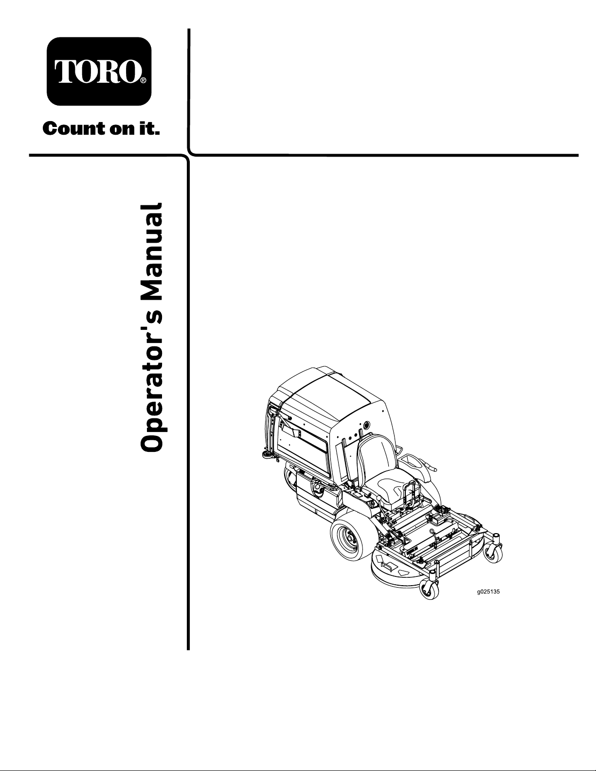
SlopeIndicator
G011841
Figure3
Thispagemaybecopiedforpersonaluse.
1.Themaximumslopeyoucansafelyoperatethemachineonis15degrees.Usetheslopecharttodeterminethedegreeofslope
ofhillsbeforeoperating.Donotoperatethismachineonaslopegreaterthan15degrees.Foldalongtheappropriateline
tomatchtherecommendedslope.
2.Alignthisedgewithaverticalsurface,atree,building,fencepole,etc.
3.Exampleofhowtocompareslopewithfoldededge.
7
Page 8

SafetyandInstructionalDecals
Safetydecalsandinstructionsareeasilyvisibletotheoperatorandarelocatednearanyareaofpotential
danger.Replaceanydecalthatisdamagedorlost.
93-6696
1.Storedenergyhazard—readtheOperator'sManual.
93-7818
1.Warning—readtheOperator'sManualforinstructionson
torquingthebladebolt/nutto115-149N∙m(85-110ft-lb).
112-8760
1.Thrownobjecthazard—keepbystandersasafedistance
fromthemachine.
2.Cutting/dismembermentofhandorfoot—stayawayfrom
movingparts.
98-1977
1.Entanglementhazard,belt—stayawayfrommovingparts.
106-5517
1.Warning—donottouchthehotsurface.
112-9028
1.Warning—stayawayfrommovingparts;keepallguardsin
place.
115-4212
1.Hydraulicuidlevel
2.ReadtheOperator's
Manual.
3.Warning—donottouchthe
hotsurface.
8
Page 9
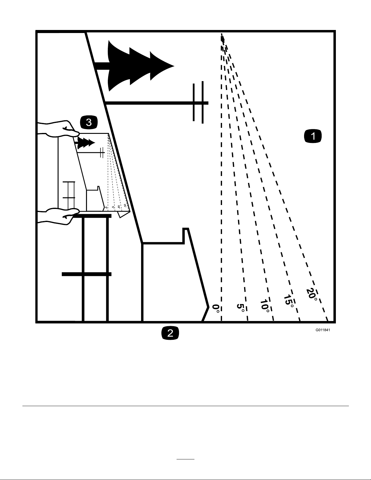
NVXXXXXX
1
2
3
4 5 6 7
116-8813
1.Hopperupindicator5.Parkingbrake
2.Battery6.Neutral
3.Hourmeter
4.PTO
7.Operatorpresenceswitch
116-8936
1.Danger—donotoperatewithdeckintilt-upposition.
116-8941
116-8934
1.Warning—disengage
bladeclutch,shutoff
engine,andremove
keybeforemaking
adjustments,servicing,
orcleaningdeck.
1.Warningfoldingdeckhazard—lockthepivotjointby
pushinginwardandrotatingtowardsthefrontofthedeck.
116-8935
2.Heightofcut.
116-8943
1.Rotatingbladeshazard—disengagePTO,movespeed
controllevertoneutral,engageparkingbrake,stopengine,
andremovekeybeforeleavingtheoperator’sposition.
Readtheinstructionsbeforeservicingorperforming
maintenance.
2.Danger—donotoperatewithmowerhopperinraised
position
9
Page 10
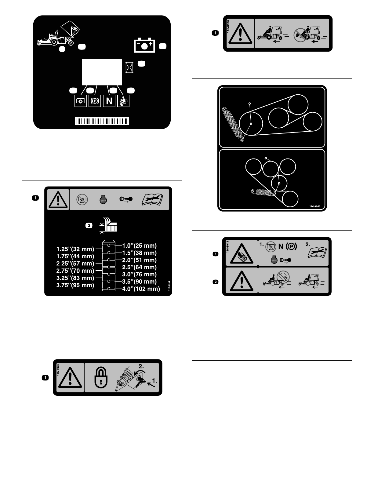
116-8946
1.Rotatecounterclockwise
torelease.
2.Rotateclockwisetolock.4.Readtheinstructions
3.Unlocktopushthe
machine.
beforeservicingor
performingmaintenance.
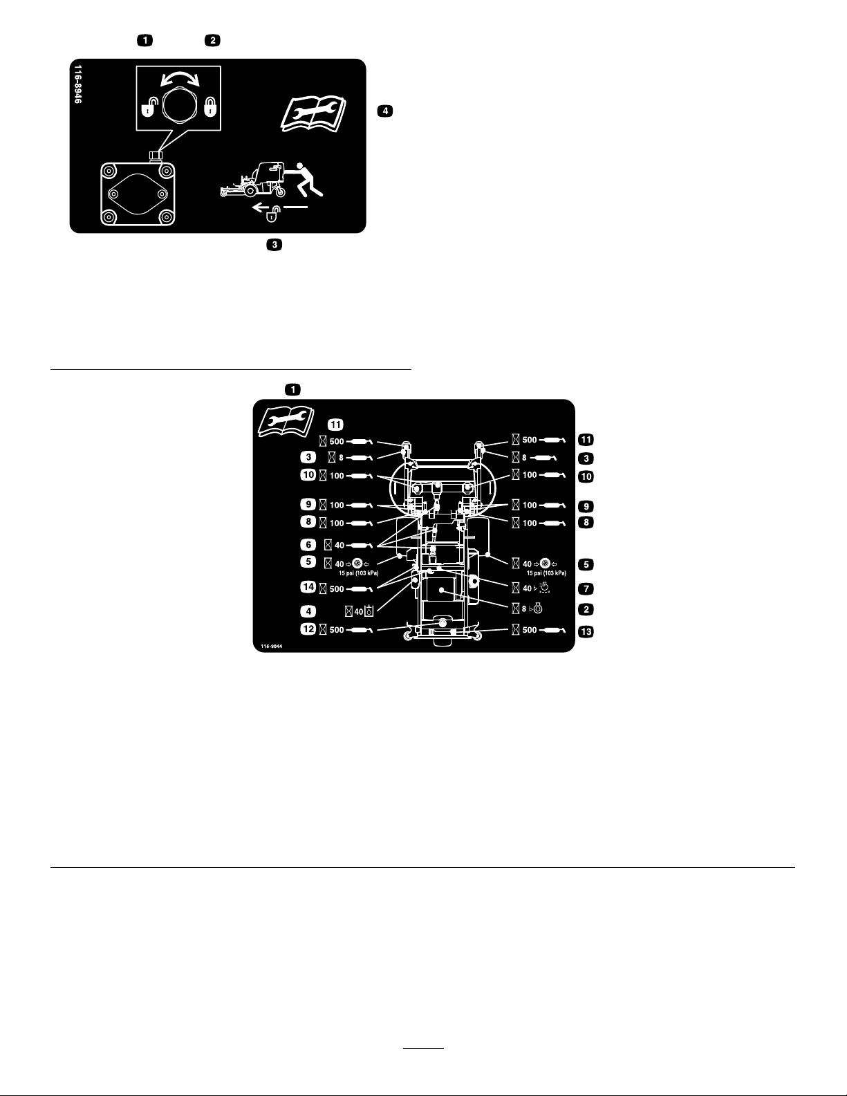
116-9044
1.ReadtheOperator’sManualbeforeperformingany
maintenance.
2.Checkengineoilevery8hours.9.Greasedeckpivotsevery100hours.
3.Greasefrontcasterwheelbearingsevery8hours.10.Checkgearboxoilevery100hours(useonlyMobil175W-90
4.Checkhydraulicuidlevelevery40hours(onlyuse
recommendedhydrooil).
5.Checktirepressureevery40hours.12.Greaserearcasterpivotevery500hours.
6.GreasedeckdrivePTOevery40hours.13.Greaserearcasterwheelevery500hours.
7.Checkaircleanerevery40hours.14.Greasebeltidlersevery500hours.
8.Greasedecklockmechanismevery100hours.
gearoil).
11.Greasefrontcasterpivotsevery500hours.
10
Page 11
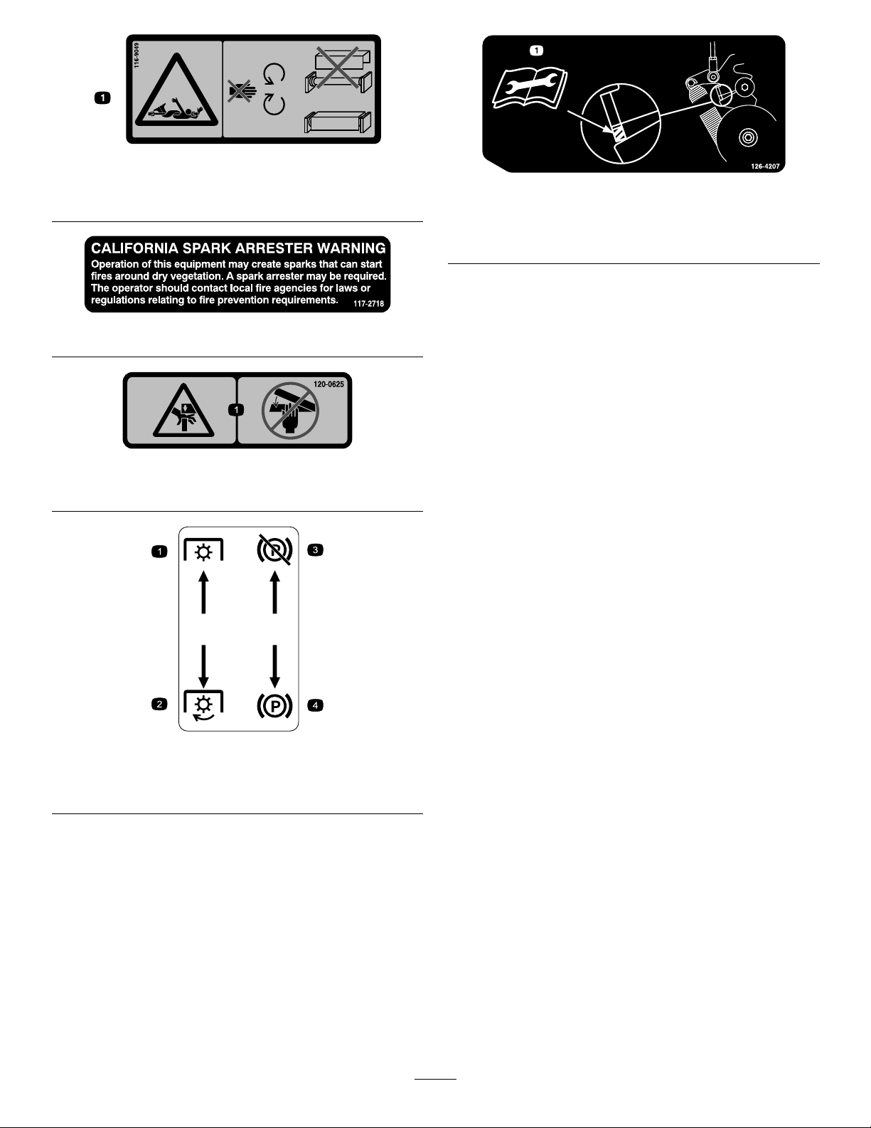
116-9049
1.Rotatingdrivelinehazard—keepalldrivelineshieldsin
place.Securelyattachbothendsofthedriveline.
117-2718
120-0625
1.Pinchpoint,hand—keephandsaway.
126-4207
1.RefertotheOperator’sManualforadjustmentprocedure.
WhenPTOisengaged,idlerarmpositionmustbein
hatchedareaoradjustmentisrequired.
MoldedinLeftConsole
1.PTO—disengage
2.PTO—engage
3.Parkbrake—release
4.Parkbrake—engage
11
Page 12
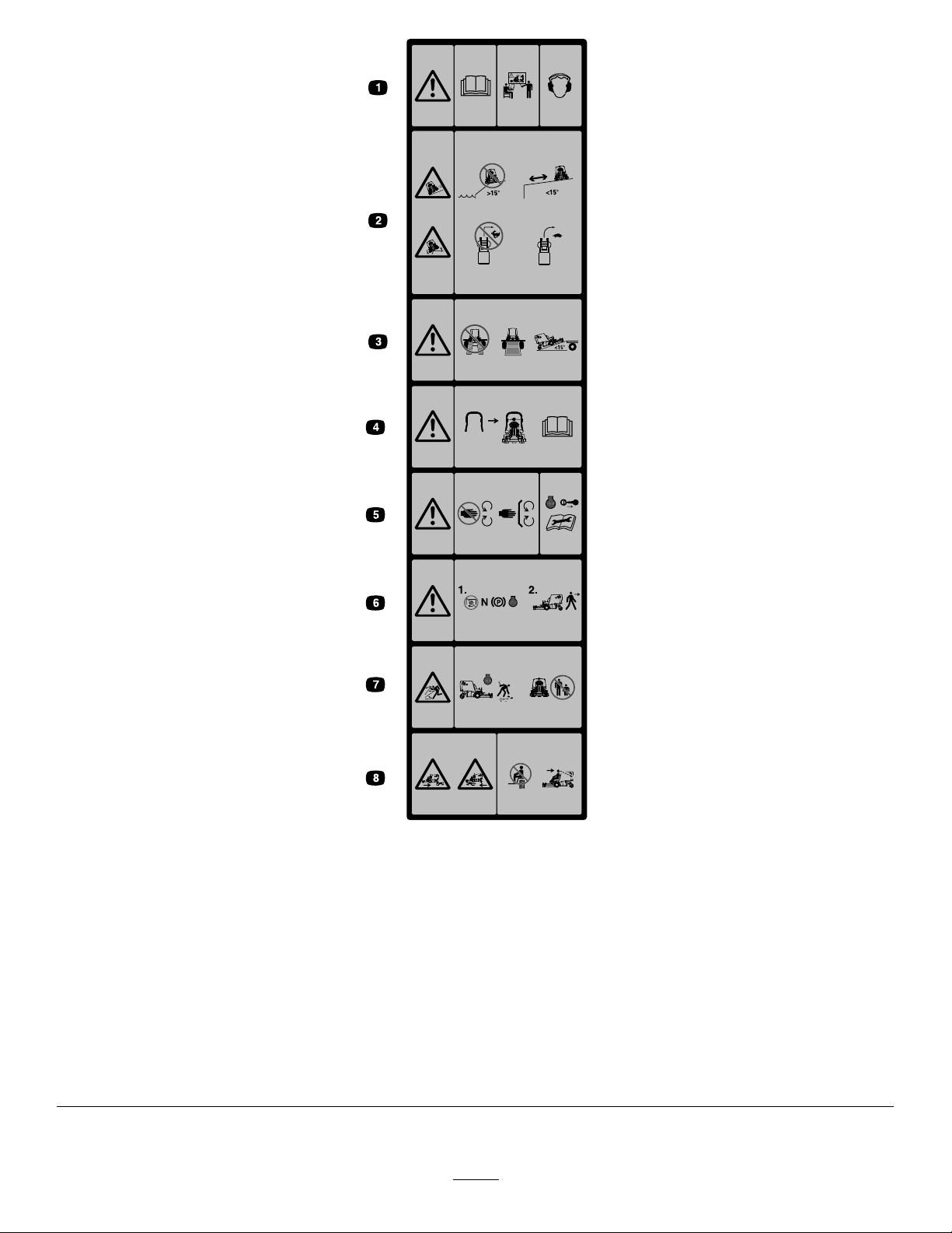
MoldedintoFrontofHopper
1.Warning-ReadtheOperator’sManual.Donotoperatethis
machineunlessyouaretrained.Wearhearingprotection.
2.Sliding,tippinghazard—Donotusethemachinenear
drop-offswithslopesgreaterthan15degrees,usethe
machineasafedistanceformdrop-offsonslopeslessthan
15degrees;Donotturnsharplywhiletravelingfast,drive
slowlywhenturning.
3.Warning—Donotusedualramps,useonepiecerampswhen
transportingmachine;Donotuserampswithinclination
greaterthan15degrees.
4.Arollbarisavailableanditsuseisrecommendedforareas
wherethereareslopes,drop-offs,orwater
5.Warning—Stayawayfrommovingparts;keepallguards
inplace.Stopengineandremovekeybeforeadjusting,
servicing,orcleaning.
6.Warning—DisengagePTO,movespeedcontrolleverto
neutralposition,engageparkingbrake,andstopengine
beforeleavingtheoperator’sposition.
7.Thrownobjecthazard—Pickupobjectsthatcouldbethrown
bymower.Donotoperatewhenpeopleandpetsareinthe
area.Keepdeectorinplace.
8.Crushing/dismembermenthazardofbystanders—Donot
carrypassengers,lookforwardanddownwhenoperatingthe
machine,lookbehindanddownwhenreversing.
12
Page 13
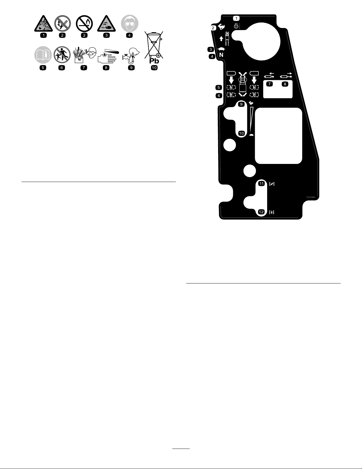
BatterySymbols
Someorallofthesesymbolsareonyourbattery
1.Explosionhazard
2.Nore,opename,or
smoking.
3.Causticliquid/chemical
burnhazard
4.Weareyeprotection9.Flusheyesimmediately
5.ReadtheOperator's
Manual.
6.Keepbystandersasafe
7.Weareyeprotection;
8.Batteryacidcancause
10.Containslead;donot
distancefromthebattery.
explosivegasescan
causeblindnessandother
injuries
blindnessorsevereburns.
withwaterandgetmedical
helpfast.
discard.
130-2880
1.Enginetemperature7.Retractthepiston
2.Fast8.Extendthepiston
3.Slow
4.Neutral
5.Neutral
6.Reverse
9.Fast
10.Slow
11.Choke—closed/on
12.Choke—open/off
13
Page 14
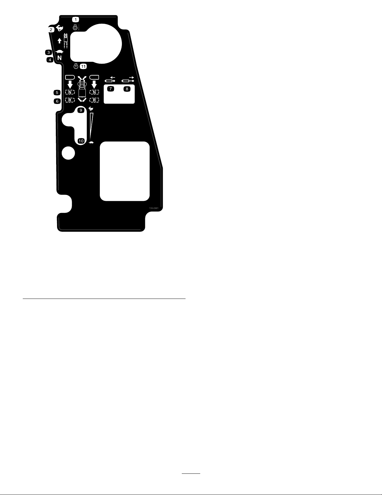
130-2881
1.Enginetemperature7.Retractthepiston
2.Fast8.Extendthepiston
3.Slow
4.Neutral
5.Neutral11.MILtoggleswitch
6.Reverse
9.Fast
10.Slow
14
Page 15
ProductOverview
Motion-ControlLevers
Usethemotion-controlleverstodrivethemachineforward
andreverse,andtoturneitherdirection.
Speed-ControlLever
Thespeed-controlleversetsmaximumforwardspeedofthe
machine(Figure4).Movingthespeed-controlleverrearward
totheNEUTRALpositionplacesthedrivesystemintoneutral.
ThrottleControl
ThethrottlecontrolisvariablebetweentheFASTandSLOW
positions.
ChokeControl(NotonEFImachines)
Usethechoketostartacoldengine.Movethechoketothe
CLOSED/ONpositiontostartacoldengine.
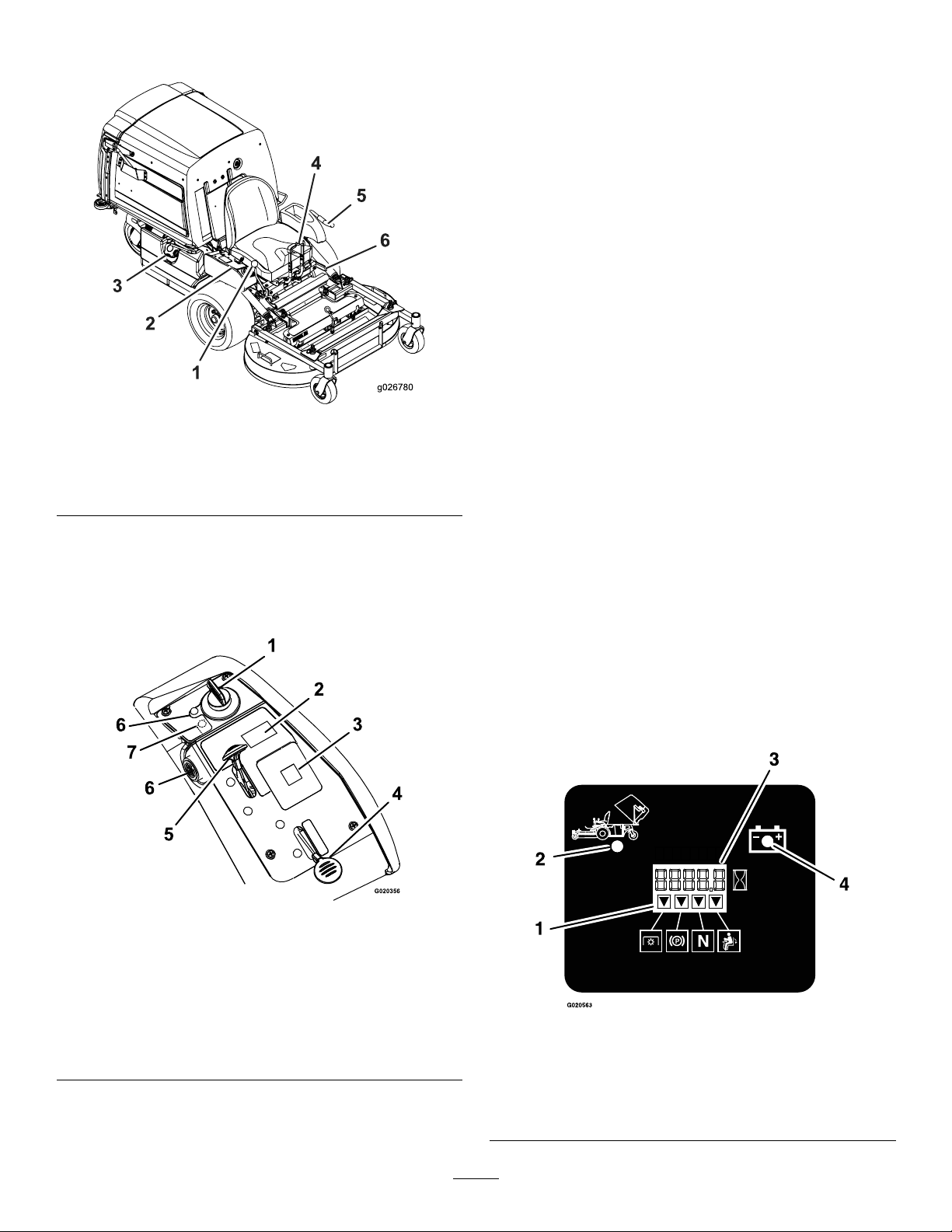
Figure4
1.Speed-controllever
2.Controls5.PTO-engagementlever
3.Fuelcap6.Parking-brakelever
4.Motion-controllevers
Controls
Becomefamiliarwithallthecontrolsbeforeyoustartthe
engineandoperatethemachine(Figure4andFigure5).
Note:DonotrunawarmenginewithchokeintheON
position.
BrakeLever
Thebrakeleverengagesaparkingbrakeonthedrivewheels
(Figure4).
IgnitionSwitch
Thisswitchisusedtostartthemowerengineandhas3
positions:START,RUN,andOFF.
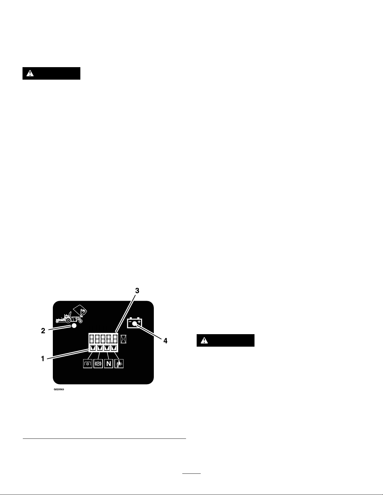
HourMeter
Thehourmeterrecordsthenumberofhourstheenginehas
operated.Thehourmeterisrecordingwhenthedecimal
pointisashingintheHour/Voltagedisplay.Usethesetimes
forschedulingregularmaintenance(Figure6).
Figure5
1.Ignitionswitch5.Throttle
2.Hopperswitch6.Engine-oiltemperature
3.Messagedisplay
4.Choke(notonEFI
machines)
7.Checkenginelight(EFI
lightandbuzzer
machinesonly)
Figure6
1.Safety-interlockindicators
2.Hopperup
3.Hour/Voltagedisplay
4.Low-voltageindicatorlight
15
Page 16

Safety-InterlockIndicators
Therearesymbolsonthehourmeterandtheyindicatewitha
blacktrianglethattheinterlockcomponentisinthecorrect
position(Figure6).
Specications
Note:Specicationsanddesignaresubjecttochange
withoutnotice.
Width
Fuel-ShutoffValve
Closethefuel-shutoffvalve(underthehopper)when
transportingorstoringthemower.
PTO-EngagementLever
UsethePTO-engagementlevertoengagethebladesandthe
blower.Pulltheleveruptoengagethebladesandblower.
Todisengagethebladesblower,pushthePTO-engagement
leverdown.
BatteryIndicatorLight
WhenyouinitiallyturntheignitionkeytotheRUNposition
forafewseconds,thebatteryvoltagedisplaysinthearea
wherethehoursnormallydisplay.
Thebatterylightturnsonwhentheignitionisturnedonand
whenthechargeisbelowthecorrectoperatinglevel(Figure
6).
Engine-Oil-TemperatureLightand
Buzzer
Theengine-oil-temperaturelightmonitorsthetemperature
oftheengineoil.Anilluminatedengine-oil-temperature
lightandintermittentbuzzingsoundsignalstheengineis
overheating.
42-inchMower
Deck
WithoutMower
Deck
WithMowerDeck
108.2cm(42.6
inches)
109.7cm(43.2
inches)
Length
42-inchMower
Deck
WithoutMower
Deck
MowerDeck—Up
Mower
Deck—Down
170.9cm(67.3
inches)
209.3cm(82.4
inches)
233.2cm(91.8
inches)
Height
42-inchMowerDeck48-inchMowerDeck
130.0cm(51.2inches)130.0cm(51.2inches)
Weight
42-inchMowerDeck48-inchMowerDeck
517kg(1,140lb)531kg(1,170lb)
48-inchMower
Deck
108.2cm(42.6
inches)
125.0cm(49.2
inches)
48-inchMower
Deck
170.9cm(67.3
inches)
207.6cm(81.8
inches)
240.0cm(94.5
inches)
Electronic-Control-Unit
Malfunction-IndicatorLight
Theelectronic-controlunit(ECU)continuouslymonitorsthe
operationoftheEFIsystem.
Ifthesystemdetectsaproblemorfault,the
malfunction-indicatorlight(MIL)illuminates.
TheMILislocatedintherightconsolepanel.
IftheMILilluminates,performtheinitialtroubleshooting
checks;refertotheMILsectioninTroubleshooting(page58).
Ifthesechecksdonotcorrecttheproblem,furtherdiagnosis
andservicingbyanAuthorizedServiceDealerisnecessary.
Attachments/Accessories
AselectionofToroapprovedattachmentsandaccessoriesis
availableforusewiththemachinetoenhanceandexpand
itscapabilities.ContactyourAuthorizedServiceDealeror
Distributororgotowww .Toro.comforalistofallapproved
attachmentsandaccessories.
16
Page 17

Operation
Note:Determinetheleftandrightsidesofthemachine
fromthenormaloperatingposition.
AddingFuel
•Forbestresults,useonlyclean,fresh(lessthan30days
old),unleadedgasolinewithanoctaneratingof87or
higher((R+M)/2ratingmethod).
•Ethanol:Gasolinewithupto10%ethanol(gasohol)
or15%MTBE(methyltertiarybutylether)byvolume
isacceptable.EthanolandMTBEarenotthesame.
Gasolinewith15%ethanol(E15)byvolumeisnot
approvedforuse.Neverusegasolinethatcontainsmore
than10%ethanolbyvolume,suchasE15(contains15%
ethanol),E20(contains20%ethanol),orE85(contains
upto85%ethanol).Usingunapprovedgasolinemay
causeperformanceproblemsand/orenginedamage
whichmaynotbecoveredunderwarranty.
•Donotusegasolinecontainingmethanol.
•Donotstorefueleitherinthefueltankorfuelcontainers
overthewinterunlessafuelstabilizerisused.
•Donotaddoiltogasoline.
DANGER
Incertainconditionsduringfueling,static
electricitycanbereleased,causingasparkthatcan
ignitethegasolinevapors.Areorexplosionfrom
gasolinecanburnyouandothersandcandamage
property.
•Alwaysplacegasolinecontainersontheground
awayfromyourvehiclebeforelling.
•Donotllgasolinecontainersinsideavehicleor
onatruckortrailerbed,becauseinteriorcarpets
orplastictruckbedlinersmayinsulatethe
containerandslowthelossofanystaticcharge.
•Whenpractical,removegas-poweredequipment
fromthetruckortrailerandrefueltheequipment
withitswheelsontheground.
•Ifthisisnotpossible,thenrefuelsuch
equipmentonatruckortrailerfromaportable
containerratherthanfromagasoline-dispenser
nozzle.
•Ifyoumustuseagasoline-dispensernozzle,
keepthenozzleincontactwiththerimofthe
fueltankorcontaineropeningatalltimesuntil
fuelingiscomplete.
DANGER
Incertainconditions,gasolineisextremely
ammableandhighlyexplosive.Areorexplosion
fromgasolinecanburnyouandothersandcan
damageproperty.
•Fillthefueltankoutdoors,inanopenarea,
whentheengineiscold.Wipeupanygasoline
thatspills.
•Neverllthefueltankinsideanenclosedtrailer.
•Donotllthefueltankcompletelyfull.Add
gasolinetothefueltankuntilthelevelis6to13
mm(1/4to1/2inch)belowthebottomofthe
llerneck.Thisemptyspaceinthetankallows
gasolinetoexpand.
•Neversmokewhenhandlinggasoline,andstay
awayfromanopenameorwheregasoline
fumesmaybeignitedbyaspark.
•Storegasolineinanapprovedcontainerand
keepitoutofthereachofchildren.Neverbuy
morethana30-daysupplyofgasoline.
•Donotoperatewithoutentireexhaustsystemin
placeandinproperworkingcondition.
WARNING
Gasolineisharmfulorfatalifswallowed.Long-term
exposuretovaporscancauseseriousinjuryand
illness.
•Avoidprolongedbreathingofvapors.
•Keepfaceawayfromnozzleandgastankor
conditionerbottleopening.
•Avoidcontactwithskin;washoffspillswith
soapandwater.
UsingStabilizer/Conditioner
Useafuelstabilizer/conditionerinthemachinetoprovide
thefollowingbenets:
•Keepsgasolinefreshduringstorageof90daysorless.
Forlongerstorage,drainthefueltank.
•Cleanstheenginewhileitruns
•Eliminatesgum-likevarnishbuildupinthefuelsystem,
whichcauseshardstarting
Important:Donotusefueladditivescontaining
methanolorethanol.
Addthecorrectamountofgasolinestabilizer/conditioner
tothegasoline.
Note:Afuelstabilizer/conditionerismosteffective
whenmixedwithfreshgasoline.Tominimizethechance
17
Page 18
ofvarnishdepositsinthefuelsystem,usefuelstabilizer
G009027
1
2
atalltimes.
FillingtheFuelTank
1.Parkthemachineonlevelground.
2.Shuttheengineoffandsettheparkingbrake.
3.Cleanaroundthefuel-tankcapandremoveit.
4.Addregularunleadedgasolinetothefueltankuntil
thelevelis6to13mm(1/4to1/2inch)belowthe
bottomofthellerneck.
Note:Thisspaceinthetankallowsthegasolineto
expand.Donotllthefueltankcompletelyfull;refer
to(Figure4).
CheckingtheEngine-OilLevel
Beforeyoustarttheengineandusethemachine,check
theoillevelintheenginecrankcase;refertoCheckingthe
Engine-OilLevel(page33).
BreakinginaNewMachine
Newenginestaketimetodevelopfullpower.Mowerdecks
anddrivesystemshavehigherfrictionwhennew,placing
additionalloadontheengine.Allow40to50hoursof
break-intimefornewmachinestodevelopfullpowerand
bestperformance.
ThinkSafetyFirst
Pleasereadallsafetyinstructionsandsymbolsinthesafety
section.Knowingthisinformationcouldhelpyouor
bystandersavoidinjury.
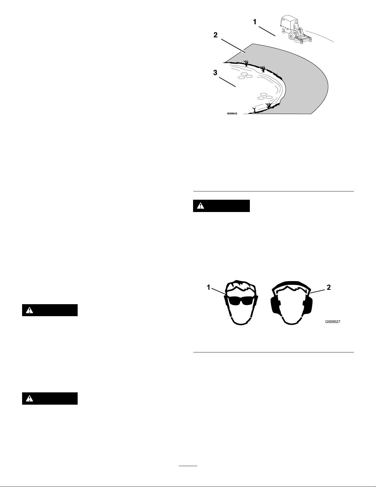
Figure7
1.Safezone—usethe
machinehereonslopes
lessthan15degreesor
atareas.
2.Dangerzone—useawalk
behindmowerand/ora
handtrimmeronslopes
greaterthan15degrees,
neardrop-offsandwater.
3.Water
CAUTION
Thismachineproducessoundlevelsinexcessof
85dBAattheoperator’searandcancausehearing
lossthroughextendedperiodsofexposure.
Wearhearingprotectionwhenoperatingthis
machine.
Useprotectiveequipmentforyourseyes,ears,hands,andfeet.
DANGER
Operatingthemachineonwetgrassorsteepslopes
cancauseslidingandlossofcontrol.
•Donotoperateonslopesgreaterthan15degrees.
1.Weareyeprotection.2.Wearhearingprotection.
Figure8
•Reducespeedanduseextremecautionon
slopes.
•Donotoperatethemachinenearwater.
DANGER
Wheelsdroppingoveredgescancauserollovers,
whichmayresultinseriousinjury,death,or
drowning.
Donotoperatethemachineneardrop-offs.
18
Page 19
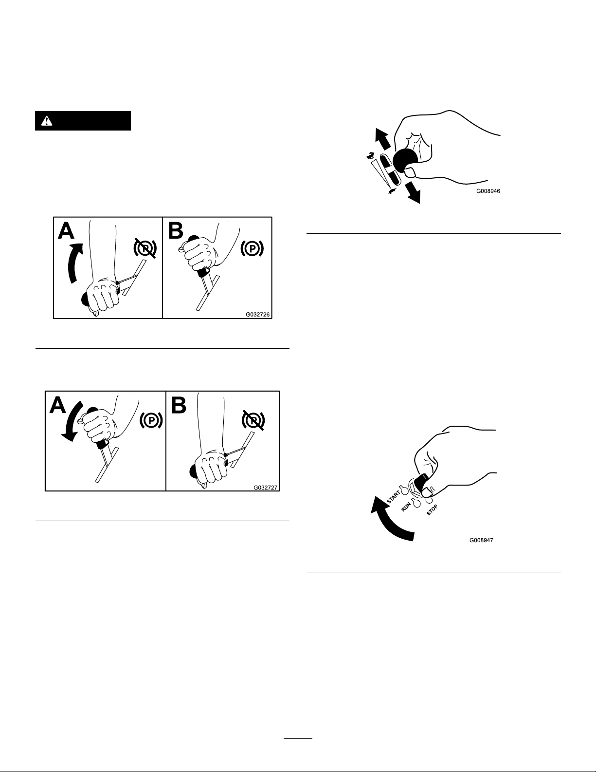
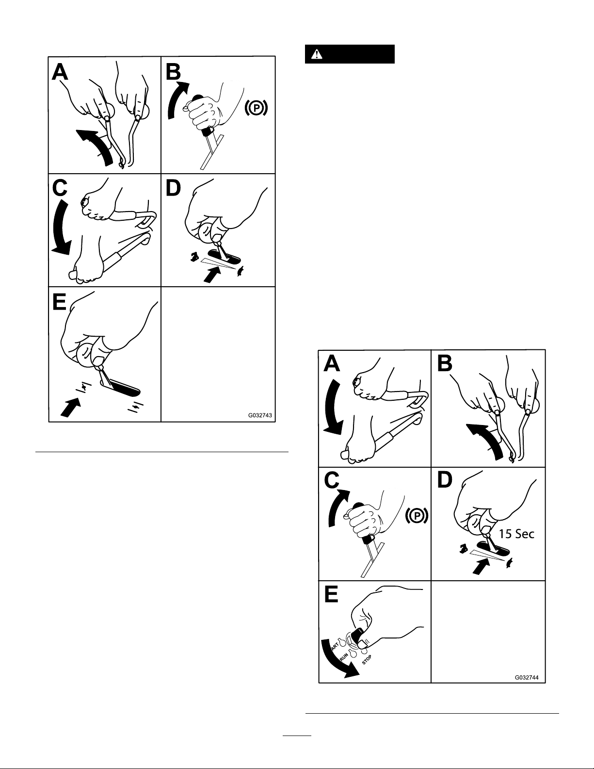
OperatingtheParkingBrake
G008946
START
RUN
STOP
G008947
OperatingtheThrottle
Alwayssettheparkingbrakewhenyoustopthemachineor
leaveitunattended.
SettingtheParkingBrake
WARNING
Theparkingbrakemaynotholdamachineparked
onaslopeandcouldcausepersonalinjuryor
propertydamage.
Donotparkthemachineonslopesunlessthe
wheelsarechockedorblocked.
Figure9
ReleasingtheParkingBrake
YoucanmovethethrottlecontrolbetweentheFASTand
SLOWpositions(Figure11).
Alwaysusethemiddlepositionwhenturningonthemower
deckandblowerwiththePTO-engagementlever.
Figure11
OperatingtheIgnitionSwitch
1.TurntheignitionkeytotheSTARTposition(Figure12).
Note:Whentheenginestarts,releasethekey.
Important:Donotengagethestarterformore
than5secondsatatime.Iftheenginefailsto
start,wait15secondsbetweenattempts.Failureto
followtheseinstructionscanburnoutthestarter
motor.
Note:Youmayneedmultipleattemptstostartthe
enginewhenyoustartitthersttimeafterthefuel
systemhasbeenwithoutfuelcompletely.
Figure10
Figure12
2.TurntheignitionkeytotheSTOPpositiontostopthe
engine.
19
Page 20
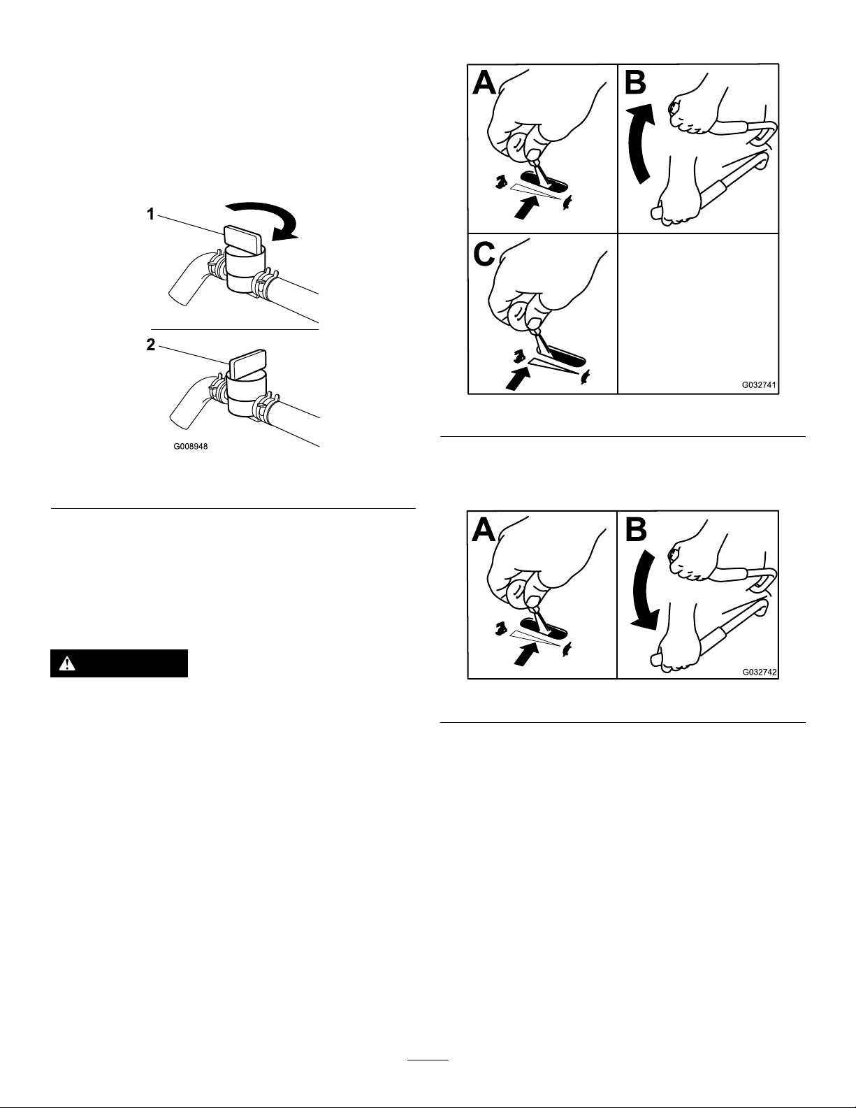
UsingtheFuel-ShutoffValve
G008948
1
2
Thefuel-shutoffvalveislocatedunderthehopper.Raisethe
hoppertoaccessit.
Closethefuel-shutoffvalvefortransport,maintenance,and
storage.
Ensurethatthefuel-shutoffvalveisopenwhenstartingthe
engine.
EngagingthePTO-EngagementLever
Figure14
Figure13
DisengagingthePTO-Engagement
1.On2.Off
Lever
Operatingthe PTO-EngagementLever
ThePTO-engagementleverstartsandstopsthemower
bladesandblower.
WARNING
Anuncovereddischargeopeningallowsobjectsto
bethrownatyouandbystanders.Also,contactwith
theblowerbladescouldoccur.Thrownobjectsor
bladecontactcancauseseriousinjuryordeath.
Neveroperatethemowerwiththehopperorhopper
doorraised,removed,oraltered.
StartingandStoppingthe Engine
StartingtheEngine
1.Movethespeed-controllevertotheNEUTRALposition.
2.Settheparkingbrake;refertoSettingtheParking
Brake(page19).
Figure15
3.MovethePTO-engagementlevertotheOFFposition
(Figure16).
4.MovethethrottlelevermidwaybetweentheSLOWand
FASTpositions.
5.ForEFImachines:Onacoldengine,pushthechoke
leverforwardintotheCLOSED/ONposition.On
20
Page 21
awarmengine,leavethechokeintheOPEN/OFF
position.
StoppingtheEngine
CAUTION
Childrenorbystandersmaybeinjuredifthey
moveorattempttooperatethemachinewhileitis
unattended.
Alwaysremovetheignitionkeyandsettheparking
brakewhenleavingthemachineunattended,even
ifjustforafewminutes.
Important:Makesurethatthefuel-shutoffvalveis
closedbeforetransportingorstoringthemachine,as
fuelleakagemayoccur.Settheparkingbrakebefore
transporting.Makesuretoremovethekeyasthefuel
pumpmayrunandcausethebatterytolosecharge.
1.DisengagethePTO .
2.Movespeed-controllevertotheNEUTRALposition.
3.Engagetheparkingbrake.
4.Placethethrottleinthemiddleposition.
5.Allowtheenginetorunforaminimumof15seconds,
thenturntheignitionswitchtotheOFFpositionto
stoptheengine.
6.Removethekeytopreventchildrenorother
unauthorizedpersonsfromstartingengine.
Figure16
6.TurntheignitionkeytotheSTARTposition(Figure
12).Whentheenginestarts,releasethekey.
Important:Donotcranktheenginecontinuously
formorethan10secondsatatime.Iftheengine
doesnotstart,wait60secondsbetweenstarting
attempts.Failuretofollowtheseguidelinescan
burnoutthestartermotor.
Note:Additionalstartingcyclesmayberequired
whenstartingtheengineforthersttimeafterthefuel
systemhasbeenwithoutfuelcompletely.
7.IfthechokeisintheCLOSED/ONposition,gradually
returnchoketotheOPEN/OFFpositionastheengine
warmsup.
Figure17
21
Page 22
7.Closethefuel-shutoffvalvewhenthemachinewillnot
beinuseforafewdays,whentransporting,orwhen
theunitisparkedinsideabuilding.
TheSafety-InterlockSystem
CAUTION
Ifthesafety-interlockswitchesaredisconnectedor
damaged,themachinecouldoperateunexpectedly,
causingpersonalinjury.
•Donottamperwiththeinterlockswitches.
•Checktheoperationoftheinterlockswitches
dailyandreplaceanydamagedswitchesbefore
operatingthemachine.
UnderstandingtheSafety-Interlock
System
Thesafety-interlocksystemisdesignedtopreventtheengine
fromstartingunless:
•Theparkingbrakeisengaged.
•ThePTO-engagementleverisdisengaged.
•Thespeed-controlleverisintheNEUTRALposition
TestingtheSafety-InterlockSystem
ServiceInterval:Beforeeachuseordaily
Testthesafety-interlocksystembeforeyouusethemachine
eachtime.Ifthesafetysystemdoesnotoperateasdescribed
below,haveanAuthorizedServiceDealerrepairthesafety
systemimmediately.
1.Sitontheseat,engagetheparkingbrake,movethe
PTO-engagementlevertotheONposition,andmove
thespeed-controllevertotheNEUTRALposition.Try
startingtheengine;theengineshouldnotstart.
2.Sitontheseat,engagetheparkingbrake,andmovethe
PTO-engagementlevertotheOFFposition.Movethe
speed-controlleveroutoftheNEUTRALposition.Try
startingtheengine;theengineshouldnotstart.
3.Sitontheseat,disengagetheparkingbrake,movethe
PTO-engagementlevertotheOFFposition,andmove
thespeed-controllevertotheNEUTRALposition.Try
startingtheengine;theengineshouldnotstart.
4.Sitontheseat,engagetheparkingbrake,movethe
PTO-engagementlevertotheOFFposition,andmove
thespeed-controllevertotheNEUTRALposition.Now
starttheengine.Whiletheengineisrunning,release
theparkingbrake,engagethePTO-engagementlever,
andriseslightlyfromtheseat;theengineshouldshut
off.
Thesafety-interlocksystemisdesignedtostoptheengine
whenyourisefromtheseatwhenthePTOisengaged.
Thehourmeterhassymbolstonotifyyouwhenthe
interlockcomponentisinthecorrectposition.Whenthe
componentisinthecorrectposition,atrianglelightsupin
thecorrespondingsquare.
Figure18
1.Triangleslightupwhen
theinterlockcomponents
areinthecorrectposition.
2.Hopperup4.Low-voltageindicatorlight
3.Hour/Voltagedisplay
5.Sitontheseat,engagetheparkingbrake,movethe
PTO-engagementlevertotheOFFposition,andmove
thespeed-controllevertotheNEUTRALposition.Now
starttheengine.Movethespeed-controlleverforward;
theengineshouldshutoff.
DrivingForwardorBackward
Thethrottlecontrolregulatestheenginespeedasmeasured
inrpm(revolutionsperminute).Placethethrottlecontrolin
thefastpositionforbestperformance.Alwaysoperateinthe
fullthrottlepositionwhenmowing.
CAUTION
Machinecanspinveryrapidly.Operatormaylose
controlofmachineandcausepersonalinjuryor
damagetomachine.
•Usecautionwhenmakingturns.
•Slowthemachinedownbeforemakingsharp
turns.
22
Page 23
DrivingForward
Note:Tobeginmovement(forwardorbackward)the
operatormustbeintheseat,thebrakelevermustbe
disengaged(pusheddown)beforethespeedcontrollevercan
bemovedforwardortheenginewillstop.
Tostop,pullthespeedcontrollevertotheneutralposition.
1.Starttheengine.
2.Releasetheparkingbrake;referto(page).
WARNING
Incorrectlyraisingorloweringamowerdeck
canbedangerous.Adroppedmowerdeckcan
resultinaseriousinjuryorpropertydamage.
•Alwaysraiseandlowerthemowerdeckon
at,dryground,freeofanyobstructions.
•Firmlygraspthemower-deck-lifthandle
andloweritinaslow,controlledmanner.
3.Tomoveforwardinastraightlinemovethespeed
controlleverforward.
Note:Themachinewillmovefasterthefartherthe
speedcontrolleverismovedawayfromneutral.
4.Toturnleftorright,pulloneofthesteeringleversback
towardneutralinthedirectiondesired.
5.Tostop,pullthespeedcontrolleverbacktotheneutral
position.
DrivingBackward
1.Tomoverearwardinastraightline,pullbothsteering
leversrearwardequally.
Toturnleftorright,releasepressureonthesteering
levertowardthedirectiondesired.
2.Tostop,releasethesteeringleverstotheneutral
position.
StoppingtheMachine
1.Pullthespeed-controlleverbacktotheNEUTRAL
position,disengagethePTO-engagementlever,and
turntheignitionkeytotheOFFposition.
2.Settheparkingbrakewhenyouleavethemachine;
refertoSettingtheParkingBrake(page19).
•Alwaysmakesurethemowerdeckis
securelylatchedintheUporDown
position.
2.Releasethemower-decklockingpinsoneachside
(Figure19).
Figure19
1.Deck-lifthandle
2.Rotatethepintowardtherearandpulloutwardtounlock.
3.Pushthepininandrotateittowardthefronttolock.
3.Removethekeyfromtheignitionswitch.
CAUTION
Childrenorbystandersmaybeinjuredifthey
moveorattempttooperatethemachinewhileitis
unattended.
Alwaysremovetheignitionkeyandsettheparking
brakewhenleavingthemachineunattended,even
ifjustforafewminutes.
RaisingtheMowerDeckinto theServicePosition
1.Shutofftheengine,waitforallmovingpartstostop,
andremovethekey.Engagetheparkingbrake.
3.Usingthedeck-lifthandle,liftthedeckupandlatchit
intheUpposition(Figure20).
Note:Thelatchislocatedatthefrontcenterofthe
seat.
23
Page 24
Thefollowingarepossiblecongurations:
•Bafesopenwithstandardblades—maximumcollection
•Bafesclosedwithstandardblades—partialmulching
•Bafesclosedwithmulchblades—intermediatemulching
•Mulchpluginstalledwithmulchblades—complete
mulching(requiresmulchkit)
AdjusttheFRSbafesasfollows:
1.Shutofftheengine,waitforallmovingpartstostop,
andremovekey.
Figure20
1.Securethemower-deck
latchontothehook.
2.Hook
3.Deck-lifthandle
WARNING
Operatingthemowerdeckintheraisedservice
positioncanbedangerous.EngagingthePTOwith
adeckintheraisedpositioncanresultinaserious
injuryorpropertydamage.
Alwayslowerandlockmowerdeckintheoperation
positionbeforeengagingthePTO.
LoweringtheMowerDeckto theOperatingPosition
1.Whilermlyholdingontodeck-lifthandle,unhookthe
mower-decklatchfromthemachineandslowlylower
themowerdecktotheground(Figure20).
2.Pushthedeck-lockingpinsinwardandrotatethem
forwardtosecurelylockthemowerdeckinthelowered
position(Figure19).
2.Engagetheparkingbrake.
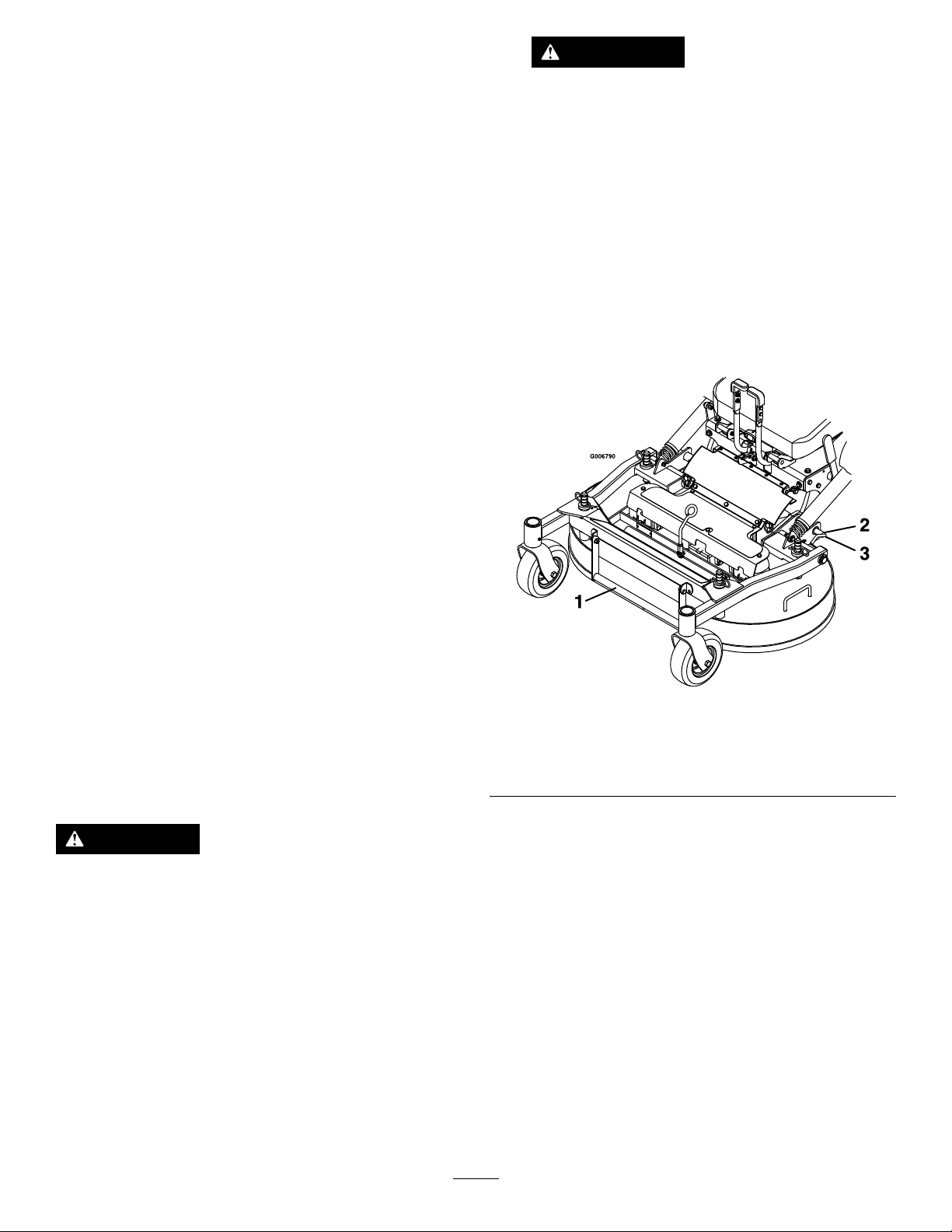
3.Removethehairpincottersandclevispinsfromboth
sidesofthePTOguard(Figure21).
4.Foldtheguardforward.
Figure21
1.Hairpincotterandclevispin
5.LoosenthelocknutsontherearstudsoftheFRS
bafes.
WARNING
Operatingthemowerwithoutthelockingpins
securelylatchedcanresultinthemowerdeck
foldingupunexpectedly .Themowerdeckfolding
upunexpectedlycancauseseriousinjury.
Alwaysoperatemowerwithlockingpinssecurely
latched.
AdjustingtheFillReduction
System(FRS)Bafes
Thellreductionsystemhasbeendesignedtoallowyouto
reducetheamountofclippingscollectedbyvaryingdegrees.
Theadvantagesincludelessfrequentemptyingofthehopper
andthereturnofnutrientstothesoil.
Figure22
1.PTOguardremovedfor
clarity
6.Raisethemowerdeck;refertoRaisingtheMower
DeckintotheServicePosition(page23).
24
2.Loosenthelocknuts.
Page 25
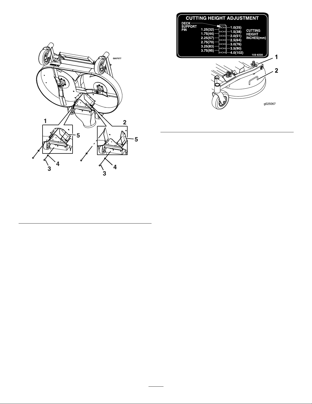
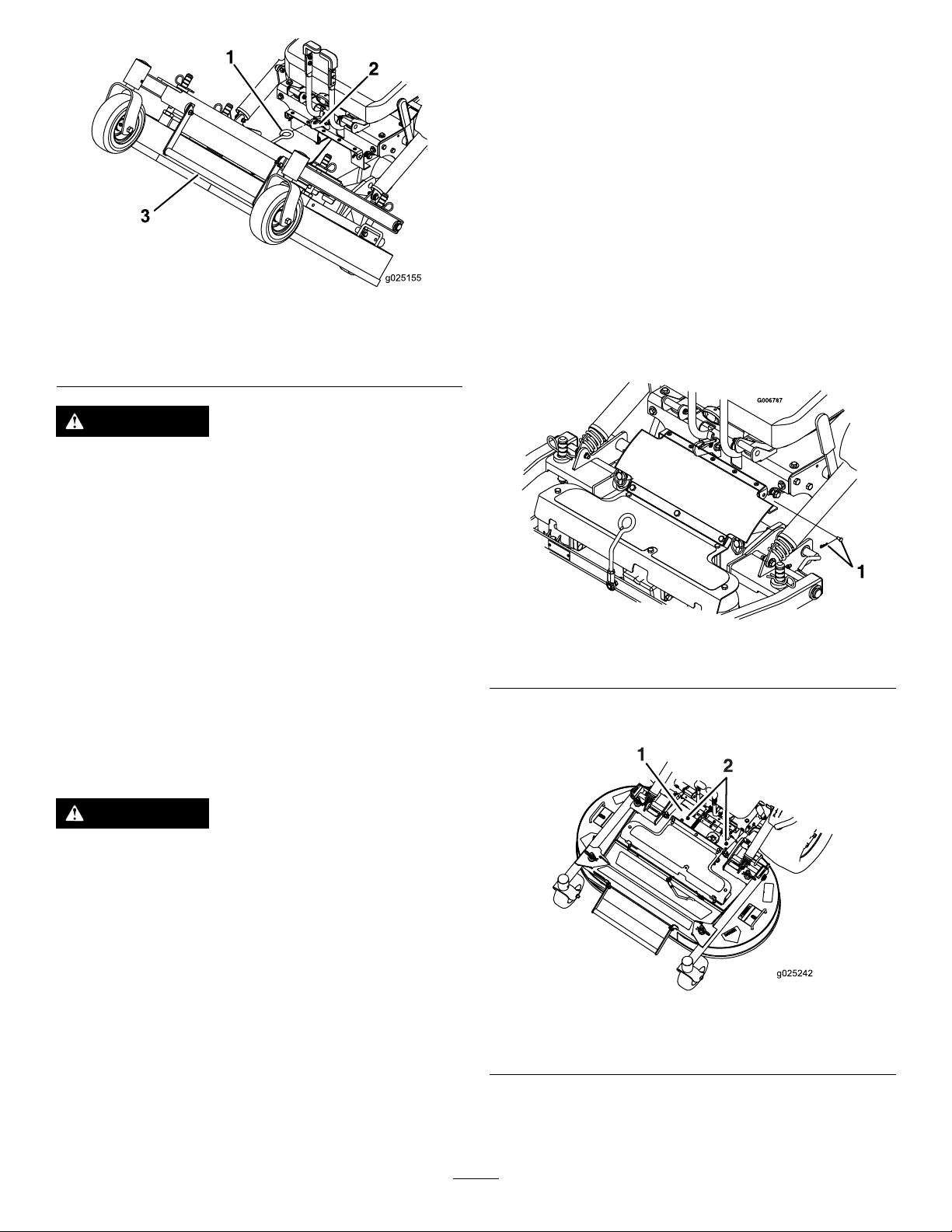
7.RemovetheboltandwasheratthefrontofeachFRS
g025067
1
2
bafe(Figure23).
8.Rotatethebafesintothedesiredpositionandinstall
theboltandwasher.
Figure24
Figure23
1.Bafes—closedposition
2.Bafes—openposition
3.Bolt
4.Washer
5.Bafes
9.Lowerthemowerdeck;refertoLoweringtheMower
DecktotheOperatingPosition(page24).
10.Slightlytightenthelocknutsontherearstudsofthe
FRSbafes.
Note:Thelocknutsontherearstudsmaybeleft
slightlylooseifyouanticipateadjustingthebafe
frequently.
11.InstallthePTOguardusingtheclevispinsandhairpin
cottersremovedinstep3.
1.Cotterpin
2.Mower-deckhandle
EmptyingtheHopper
Afullhopperisindicatedbyabuzzerlocatedbehindthe
operatorinthehopper.Emptythehopperwhenthebuzzer
soundstopreventcloggingoftheblowerorthemowerdeck.
1.DisengagethePTO ,movethespeed-controllever
totheNEUTRALposition,settheparkingbrake,and
dismountthemachine.
2.Makesurethatmachineisonadrylevelsurface.
3.Liftthereardoorupandallowittorestontopof
hopper.
4.Usingthehandlesatthelowerfrontofthehopper,
raisethehoppertodumpthecontents.
5.Lowerthehopperandclosethehopperdoor.
ClearingtheHopperScreen
Removethescreenbyrmlyliftingthescreenhandles(Figure
25).
Pullthescreentowardsthebacktoremoveit.Asneeded,
gentlytapthescreentoremovedebris.
AdjustingtheHeightofCut
Thecuttingheightofthemowerdeckisadjustedfrom2.5to
10.2cm(1to4inches)in6.3mm(1/4inch)increments.
1.Movethespeed-controllevertotheNEUTRALposition
tostopthemachine.
2.DisengagethePTO,engagetheparkingbrake,shutoff
theengine,andwaitforallmovingpartstostop.
3.Usingthemower-deckhandle,raisethemowerdeck,
andmovethecotterpinstothedesiredheight-of-cut
position.Repeatfortheoppositeside.
Note:Excessivebuilduponthescreencancausetheblower
toplug.
Note:Inconditionswherethescreenclogsquickly,youcan
turnandinstallthefrontremovablescreenpanelunderthe
primaryscreentoallowfreeairowfromthehopper.
25
Page 26

Figure25
1.Frontremovablescreen
canberotatedandstored
forwetconditions.
2.Frontremovablescreen4.Handles
UsingtheDrive-WheelRelease Valves
WARNING
3.Primaryscreen
Note:Donottowthemachine.
6.Rotatethevalvesclockwisetorunthemachine.
Note:Donotovertightenthevalves.
TransportingtheMachine
Useaheavy-dutytrailerortrucktotransportthemachine.
Ensurethatthetrailerortruckhasallnecessarybrakes,
lighting,andmarkingasrequiredbylaw .Pleasecarefullyread
allthesafetyinstructions.Knowingthisinformationcould
helpyou,yourfamily,pets,orbystandersavoidinjury.
WARNING
Drivingonthestreetorroadwaywithoutturn
signals,lights,reectivemarkings,oraslow-moving
vehicleemblemisdangerousandcanleadto
accidentscausingpersonalinjury.
Donotdrivethemachineonapublicstreetor
roadway.
Handsmaybecomeentangledintherotatingdrive
componentsbelowtheenginedeck,whichcould
resultinseriousinjury.
Shutofftheengine,removethekey,andwait
forallmovingpartstostopbeforeaccessingthe
drive-wheelreleasevalves.
WARNING
Theengineandhydraulicdriveunitscanbecome
veryhot.Touchingahotengineorhydraulicdrive
unitscancausesevereburns.
Waitfortheengineandhydraulicdriveunitstocool
completelybeforeaccessingthedrive-wheelrelease
valves.
Thedrive-wheelreleasevalvesarelocatedonthetop,left,
frontcornerofhydrostaticpumps.
1.Movethespeed-controllevertotheNEUTRALposition
tostopthemachine.
2.DisengagethePTOlever,engagetheparkingbrake,
shutofftheengine,andwaitforallmovingpartsto
stop.
3.Tilttheseatuptogainaccesstothepumps.
4.Rotatebothreleasevalves1turncounterclockwiseto
releasethedrivesystem.
Note:Thisallowsthehydraulicuidtobypassthe
pump,enablingthewheelstoturn.
1.Ifusingatrailer,connectittothetowingvehicleand
connectthesafetychains.
2.Ifapplicable,connectthetrailerbrakes.
3.Loadthemachineontothetrailerortruck.
4.Shutofftheengine,removethekey,setthebrake,and
closethefuelvalve.
5.Securelyfastenthemachinetothetrailerortruckwith
straps,chains,cable,orropesdownandoutwardfrom
themachine.
LoadingtheMachine
Useextremecautionwhenloadingortheunloadingmachine
ontoatraileroratruck.Useafull-widthrampthatiswider
thanthemachineforthisprocedure.
Important:Ifafullwidthrampisnotavailable,use
enoughindividualrampstosimulateafullwidthramp.
Ensurethattherampislongenoughsothattheanglewith
thegrounddoesnotexceed15degrees.Asteeperangle
maycausemowercomponentstogetcaughtasthemachine
movesfromtheramptothetrailerortruck.Steeperangles
mayalsocausethemachinetotiporlosecontrol.Ifyouare
loadingthemachineonornearaslope,positionthetraileror
trucksothatitisonthedownsideoftheslopeandtheramp
extendsuptheslope.Thisminimizestherampangle.
Important:Donotattempttoturnthemachinewhile
ontheramp,youmayloosecontrolanddriveofftheside.
5.Disengagetheparkingbrakebeforepushingthe
machine.
26
Page 27

WARNING
Loadingamachineontoatrailerortruckincreases
thepossibilityofatip-overandcouldcauseserious
injuryordeath.
•Useextremecautionwhenoperatingamachine
onaramp.
•Useonlyafull-widthramp;donotuseindividual
rampsforeachsideofthemachine.
•Ifafullwidthrampisnotavailable,useenough
individualrampstosimulateafullwidthramp.
•Donotexceeda15-degreeanglebetweenthe
rampandthegroundorbetweentherampand
thetrailerortruck.
•Avoidsuddenaccelerationordecelerationwhile
drivingthemachineonarampasthiscould
causealossofcontroloratip-over.
27
Page 28

OperatingTips
KeepingtheUndersideoftheMower
Clean
UsingtheFastThrottleSetting
Forbestmowingandmaximumaircirculation,operatethe
engineattheFASTposition.Airisrequiredtothoroughlycut
grassclippings,sodonotsettheheight-of-cutsolowasto
totallysurroundthemowerinuncutgrass.Alwaystrytohave
1sideofthemowerfreefromuncutgrass,whichallowsair
tobedrawnintothemower.
CuttingaLawnfortheFirstTime
Cutgrassslightlylongerthannormaltoensurethatthe
cuttingheightofthemowerdoesnotscalpanyuneven
ground.However,thecuttingheightusedinthepastis
generallythebestonetouse.Whencuttinggrasslongerthan
15cm(6inches)tall,youmaywanttocutthelawntwiceto
ensureanacceptablequalityofcut.
CuttingaThirdoftheGrassBlade
Itisbesttocutonlyaboutathirdofthegrassblade.Cutting
morethanthatisnotrecommendedunlessgrassissparse,or
itislatefallwhengrassgrowsmoreslowly.
Cleanclippingsanddirtfromtheundersideofthemower
aftereachuse.Ifgrassanddirtbuildupinsidethemower,
cuttingqualitywilleventuallybecomeunsatisfactory.
MaintainingtheBlade(s)
Maintainasharpbladethroughoutthecuttingseasonbecause
asharpbladecutscleanlywithouttearingorshreddingthe
grassblades.Tearingandshreddingturnsgrassbrownat
theedges,whichslowsgrowthandincreasesthechanceof
disease.Checkthemowerbladesaftereachuseforsharpness,
andforanywearordamage.Filedownanynicksandsharpen
thebladesasnecessary.Ifabladeisdamagedorworn,replace
itimmediatelywithagenuineTororeplacementblade.
AlternatingtheMowingDirection
Alternatethemowingdirectiontokeepthegrassstanding
straight.Thisalsohelpsdisperseclippingswhichenhances
decompositionandfertilization.
MowingatCorrectIntervals
Grassgrowsatdifferentratesatdifferenttimesoftheyear.
Tomaintainthesamecuttingheight,mowmoreofteninearly
spring.Asthegrassgrowthrateslowsinmidsummer,mow
lessfrequently .Ifyoucannotmowforanextendedperiod,
rstmowatahighcuttingheight,thenmowagain2days
lateratalowerheightsetting.
UsingaSlowerCuttingSpeed
Toimprovecutquality,useaslowergroundspeedincertain
conditions.
AvoidingCuttingTooLow
Whenmowinguneventurf,raisethecuttingheighttoavoid
scalpingtheturf.
Stopping
Ifyoumuststoptheforwardmotionofthemachinewhile
mowing,aclumpofgrassclippingsmaydropontoyour
lawn.Toavoidthis,moveontoapreviouslycutareawiththe
bladesengagedoryoucandisengagethemowerdeckwhile
movingforward.
28
Page 29

Maintenance
RecommendedMaintenanceSchedule(s)
MaintenanceService
Interval
Aftertherst50hours
Aftertherst100hours
Beforeeachuseordaily
Every40hours
Every50hours
Every100hours
MaintenanceProcedure
•Changetheoilinall3gearboxhousingsandaddoilasneeded.
•Checkthewheel-lugnuttorque.
•Checkthewheel-hubnuttorque.
•Checktheparkingbrakeadjustment.
•Changethehydrauliclterandreservoirhydraulicuidwhenusinganytypeofoil.
•Checkthesafety-interlocksystem.
•Greasethefrontcasterwheelhubs(moreoftenindirtyordustyconditions).
•Checktheengine-oillevel.
•Cleantheenginescreenandtheoilcooler.
•Cleanthehydraulicpumps.
•Checkthemowerblades.
•Cleanthemowerdeck.
•Cleandebrisfromthemachine.
•Greasethedriveshaft(moreoftenindirtyordustyconditions).
•Checkthetirepressure.
•Inspectthebeltsforcracksandwear.
•Checkthehydraulicuidlevel.
•Checksparkarrester(ifequipped).
•Greasethemower-deckip-uppivot(moreoftenindirtyordustyconditions).
•Greasethemower-deckpush-armtubes(moreoftenindirtyordustyconditions).
•Changetheoilinall3gearboxhousingsandaddoilasneeded.
•Changetheengineoil(moreoftenindirtyordustyconditions).
•Cleantheengine-oilcooler.
•Checkandcleanenginecoolingnsandshrouds.
Every150hours
Every160hours
Every200hours
Every250hours
Every500hours
•Inspecttheprimarylterandair-inletscreen.
•Lubricatethebrake-handlepivot.
•Lubricatingthebrake-rodbushingsandsteeringlinkagerodends.
•Changetheengineoillter.
•Checkandgapthesparkplug(EFIenginesonly).
•Replacethefuellter(moreoftenindirtyordustyconditions).
•Replacetheprimaryairlter(moreoftenindustyorsandyconditions).
•Checkthesafetyairlter.
•ChangethehydrauliclterandreservoirhydraulicuidwhenusingMobil®1oil
(moreoftenindirtyordustyconditions).
•Replacethesafetyairlter.
•Checkandgapthesparkplug(Non-EFIenginesonly).
•Checkthewheel-lugnuttorque.
•Checkthewheel-hubnuttorque.
•Adjustthecaster-pivotbearings.
•Checktheparkingbrakeadjustment.
•ChangethehydrauliclterandreservoirhydraulicuidwhenusingT oro®
HYPR-OIL™500hydraulicuid(moreoftenindirtyordustyconditions).
Monthly
•Checkthebattery.
29
Page 30

MaintenanceService
Interval
Yearly
MaintenanceProcedure
•Greasethefrontcasterpivots(moreoftenindirtyordustyconditions).
•Greasetherearcasterhub(moreoftenindirtyordustyconditions).
•Greasethepump-beltidlerarm(moreoftenindirtyordustyconditions).
•GreasethePTO-beltidlerarm(moreoftenindirtyordustyconditions).
•Greasetherearcasterpivot(moreoftenindirtyordustyconditions).
•Lubricatethecaster-wheelhubs.
Yearlyorbeforestorage
•Paintchippedsurfaces.
•Checkallmaintenanceprocedureslistedabovebeforestorage.
Important:Refertoyourengineowner’smanualforadditionalmaintenanceprocedures.
CAUTION
Ifyouleavethekeyintheignitionswitch,someonecouldaccidentlystarttheengineandseriouslyinjure
youorotherbystanders.
Removethekeyfromtheignitionbeforeyoudoanymaintenance.
Lubrication
LubricatingtheMachine
ServiceInterval:Beforeeachuseordaily—Greasethefront
casterwheelhubs(moreoftenindirtyor
dustyconditions).
Every40hours—Greasethedriveshaft(moreoften
indirtyordustyconditions).
Every100hours—Greasethemower-deckip-up
pivot(moreoftenindirtyordustyconditions).
Every100hours—Greasethemower-deckpush-arm
tubes(moreoftenindirtyordustyconditions).
Yearly—Greasethefrontcasterpivots(moreoftenin
dirtyordustyconditions).
Yearly—Greasetherearcasterhub(moreoftenin
dirtyordustyconditions).
Yearly—Greasethepump-beltidlerarm(moreoften
indirtyordustyconditions).
Yearly—GreasethePTO-beltidlerarm(moreoftenin
dirtyordustyconditions).
Yearly—Greasetherearcasterpivot(moreoftenin
dirtyordustyconditions).
1.Rearcasterpivot6.Frontcasterwheelhub
2.PTO-beltidlerarm7.Deckip-uppivot
3.Pump-beltidlerarm8.Push-armtubes
4.Rearcasterhub9.Frontcasterpivots
5.Driveshaft
Figure26
GreaseType:No.2lithiumormolybdenumgrease
1.DisengagethePTO,stopthemachine,shutoffthe
engine,removethekey,andwaitforallmovingpartsto
stopbeforeleavingtheoperatingposition.
2.Cleanthegreasettingswitharag.Makesuretoscrape
anypaintoffthefrontofthetting(s).
3.Connectagreaseguntothetting.Pumpgrease
intothettingsuntilgreasebeginstooozeoutofthe
bearings.
4.Wipeupanyexcessgrease.
30
Page 31

LubricatingtheCaster-WheelHubs
ServiceInterval:Yearly
1.Shutofftheengine,waitforallmovingpartstostop,
removethekey,andengagetheparkingbrake.
Note:Makesurethattheaxledoesnotextendbeyond
eithernut.
15.Installthesealguardsoverthewheelhubandinsert
wheelintothecasterfork.
16.Installthecasterboltandtightenthenutfully.
Important:Topreventsealandbearingdamage,check
thebearingadjustmentoften.Spinthecastertire.The
tireshouldnotspinfreely(morethan1or2revolutions)
orhaveanysideplay .Ifthewheelspinsfreely,adjustthe
torqueonthespacernutuntilthereisaslightamountof
drag.Applyanotherlayerofthread-lockingcompound.
LubricatingtheBrake-HandlePivot
Figure27
1.Sealguard2.Spacernutwithwrench
ats
2.Removethecasterwheelfromthecasterforks.
3.Removethesealguardsfromthewheelhub.
4.Removeaspacernutfromtheaxleassemblyinthe
casterwheel.
Note:Thread-lockingcompoundhasbeenappliedto
lockthespacernutstotheaxle.
5.Removetheaxle(withtheotherspacernutstill
assembledtoit)fromthewheelassembly .
6.Pryoutthesealsandinspectthebearingsforwearor
damageandreplacethemifnecessary.
7.Packthebearingswithageneral-purposegrease.
8.Insert1bearingand1newsealintothewheel.
Note:Replacetheseals.
9.Ifbothspacernutshavebeenremoved(orbroken
loose)fromtheaxleassembly,applyathread-locking
compoundto1spacernutandthreaditontotheaxle
withthewrenchatsfacingoutward.
Note:Donotthreadthespacernutalloftheway
ontotheendoftheaxle.Leaveapproximately3mm
(1/8inch)fromtheoutersurfaceofthespacernutto
theendoftheaxleinsidethenut.
10.Inserttheassemblednutandaxleintothewheelonthe
sidewiththenewsealandbearing.
11.Withtheopenendofthewheelfacingup,llthearea
insidethewheelaroundtheaxlefullofgeneral-purpose
grease.
12.Insertthesecondbearingandnewsealintothewheel.
13.Applyathread-lockingcompoundtothesecondspacer
nutandthreaditontotheaxlewiththewrenchats
facingoutward.
14.Torquethenutto8to9N∙m(75to80in-lb),loosen
thenut,thentorqueitto2to3N∙m(20to25in-lb).
ServiceInterval:Every160hours
1.Shutofftheengine,waitforallmovingpartstostop,
removethekey,andengagetheparkingbrake.
2.Lubricatethebronzebushingsonthebrake-handle
pivotwithaspraytypelubricantorlightoil(Figure28).
Figure28
LeftSideofMachineShown
1.Brake-handlepivot
2.PTO-handlepivot
3.Spring-armpivot
4.Togglepivot
LubricatingtheBrake-RodBushings
andSteering-LinkageRodEnds
ServiceInterval:Every160hours
1.Shutofftheengine,waitforallmovingpartstostop,
removethekey,andengagetheparkingbrake.
2.Unhooktheseatlatchandtilttheseatup.
3.Lubricatethebronzebushingsoneachendofthe
brakerodshaftwithaspraytypelubricantoralightoil.
Note:Thebushingsarelocatedtotheinsideofthe
angebearings.
31
Page 32
4.Lubricateeachendofbothsteeringlinkagerodswitha
spraylubricantoralightoil.
EngineMaintenance
ChangingtheGearboxOil
ServiceInterval:Aftertherst50hours—Changetheoil
inall3gearboxhousingsandaddoilas
needed.
Every100hours—Changetheoilinall3gearbox
housingsandaddoilasneeded.
1.Placethemachineonalevelsurface.
2.Shutofftheengine,waitforallmovingpartstostop,
removethekey,andengagetheparkingbrake.
3.Removethegearboxanddrive-shaftassemblyfromthe
mowerdeck.Retainthehardwareforuselater.
4.Removethelargeoildrainplugonthefrontofeachof
the3gearboxsectionsanddraintheoil(Figure29).
Figure29
WARNING
Contactwithhotsurfacesmaycausepersonal
injury.
Keephands,feet,face,clothing,andotherbody
partsawaythemuferandotherhotsurfaces.
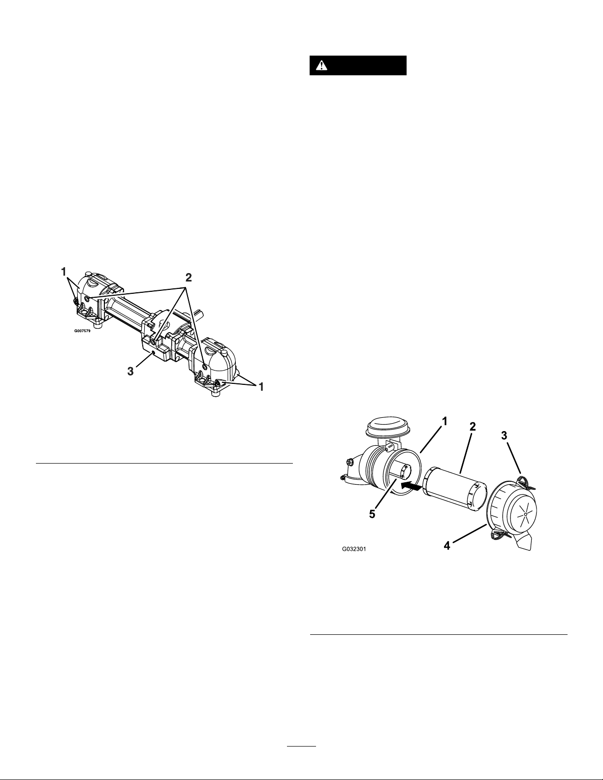
ServicingtheAirCleaner
ServiceInterval:Every150hours
Every250hours—Replacetheprimaryairlter(more
oftenindustyorsandyconditions).
Every250hours—Checkthesafetyairlter.
Every500hours—Replacethesafetyairlter.
Note:Checktheltersmorefrequentlyiftheoperating
conditionsareextremelydustyorsandy.
RemovingtheFilters
1.Disengagetheblade-controlswitch(PTO),movethe
motion-controlleverstotheNEUTRAL-LOCKposition,
andsettheparkingbrake.
2.Shutofftheengine,removethekey ,andwaitforall
movingpartstostopbeforeleavingtheoperating
position.
3.Releasethelatchesontheaircleanerandpullthe
air-cleanercoverofftheair-cleanerbody(Figure30).
1.Smallmagneticplugs
(frontandback)
2.Largeoildrain/llplug
5.Removethesmallmagneticplugsandwipeawayany
materialaccumulatedontheplugs.
6.ApplyaTeon
andinstallthemintothegearbox.
7.Installthegearboxanddrive-shaftassemblytothe
mowerdeck.
8.FillthegearboxwithMobil
gearlubeoiluntillevelwithoildrain/llplug.
Note:Eachofthegearboxsectionsmustbelled
separately.
Note:Keepthemowerdeckleveltothegroundwhen
llingthegearboxwithoil.Donotllthegearboxwith
themowerdeckraisedintheserviceposition.
9.ApplyaTeonpipesealanttothe3largeoilplugsand
installthemintothegearbox.
®
pipesealanttoallsmallmagneticplugs
3.Smallmagneticplug(front
only)
®
SHC(synthetic)75W-90
Figure30
1.Air-cleanerbody4.Air-cleanercover
2.Primarylter5.Safetylter
3.Latch
4.Cleantheinsideoftheair-cleanercoverwith
compressedair.
5.Gentlyslidetheprimarylteroutoftheair-cleaner
body(Figure30).
Note:Avoidknockingthelterintothesideofthe
body.
32
Page 33
6.Removethesafetylteronlyifyouintendtoreplaceit.
Important:Donotattempttocleanthesafety
lter.Ifthesafetylterisdirty,thentheprimary
lterisdamaged.Replacebothlters.
7.Inspecttheprimarylterfordamagebylookinginto
thelterwhileshiningabrightlightontheoutsideof
thelter.
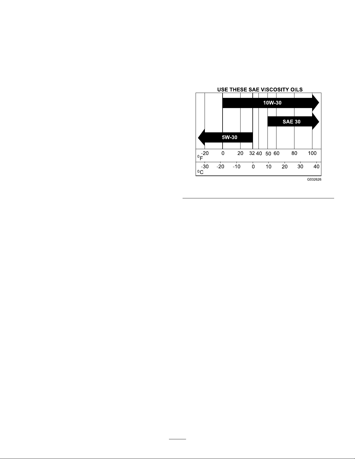
ServicingtheEngineOil
OilType:Detergentoil(APIserviceclassSJorhigher)
OilCapacity(Non-EFIengines):withalterchange,
1.8L(1.9USqt);withnolterchange,1.6L(1.7USqt)
OilCapacity(EFIengines):withalterchange,1.9L(2.0
USqt);withnolterchange,1.6L(1.7USqt)
Note:Holesinthelterappearasbrightspots.Ifthe
lterisdamaged,discardit.
ServicingthePrimaryFilter
•Iftheprimarylterisdirty,bent,ordamaged,replaceit.
•Donotcleantheprimarylter.
ServicingtheSafetyFilter
Replacethesafetylter,nevercleanit.
Important:Donotattempttocleanthesafetylter.
Ifthesafetylterisdirty,thentheprimarylteris
damaged.Replacebothlters.
InstallingtheFilters
Important:Topreventenginedamage,alwaysoperate
theenginewithbothairltersandthecoverinstalled.
1.Ifinstallingnewlters,checkeachlterforshipping
damage.
Note:Donotuseadamagedlter.
2.Ifyouarereplacingthesafetylter,carefullyslideit
intothelterbody(Figure30).
3.Carefullyslidetheprimarylteroverthesafetylter
(Figure30).
Note:Ensurethattheprimarylterisfullyseatedby
pushingonitsouterrimwhileinstallingit.
Important:Donotpressonthesoftinsidearea
ofthelter.
4.Installtheair-cleanercoverwiththesideindicatedas
upfacingupwardandsecurethelatches(Figure30).
Viscosity:Seethetablebelow.
Figure31
CheckingtheEngine-OilLevel
ServiceInterval:Beforeeachuseordaily
Note:Checktheoilwhentheengineiscold.
Important:Donotoverllthecrankcasewithoil
becausedamagetotheenginemayresult.Donotrun
enginewithoilbelowthelowmarkbecausetheengine
maybedamaged.
1.Movethespeed-controllevertotheNEUTRALposition
tostopthemachine.
2.DisengagethePTO,engagetheparkingbrake,shutoff
theengine,andwaitforallmovingpartstostop.
3.Allowtheenginetocool.
4.Raisethehopper
5.Cleantheareaaroundthedipstick(Figure32).
6.Removethedipstickandwipetheoiloff.
7.Insertthedipstickandpushitallthewaydowninto
thetube.
8.Removethedipstickandreadtheoillevel.
9.Iftheoillevelislow,wipeofftheareaaroundthe
oil-llcap,removecapandlltothefullmarkonthe
dipstick(Figure32).
Important:Donotoperatetheenginewiththeoil
levelbelowthelow(oradd)markonthedipstick
oroverthefullmark.
33
Page 34
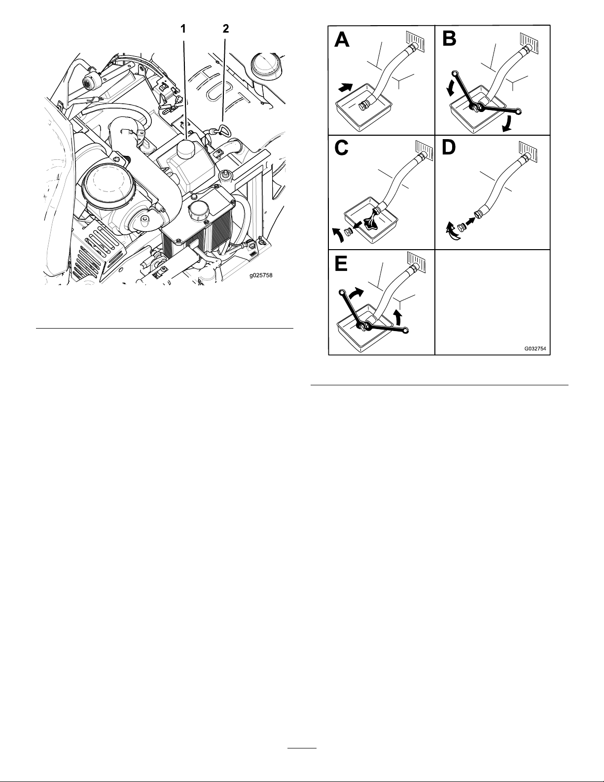
Figure32
1.Oil-llcap2.Oildipstick
ChangingtheEngineOil
ServiceInterval:Every100hours(moreoftenindirtyor
dustyconditions).
Note:Disposeoftheusedoilatarecyclingcenter.
1.Parkthemachinesothattherearisslightlylowerthan
thefronttoensurethattheoildrainscompletely.
2.Movethespeed-controllevertotheNEUTRALposition
tostopthemachine.
3.DisengagethePTO,engagetheparkingbrake,shutoff
theengine,andwaitforallmovingpartstostop.
Figure33
4.Slowlypourapproximately80%ofthespeciedoil
intothellertubeandslowlyaddtheadditionaloilto
bringittothefullmarkonthedipstick(Figure32).
5.Starttheengineanddrivetoaatarea.Checktheoil
levelagain(Figure32).
6.Ifneeded,addoiltothefullmarkonthedipstick.
34
Page 35
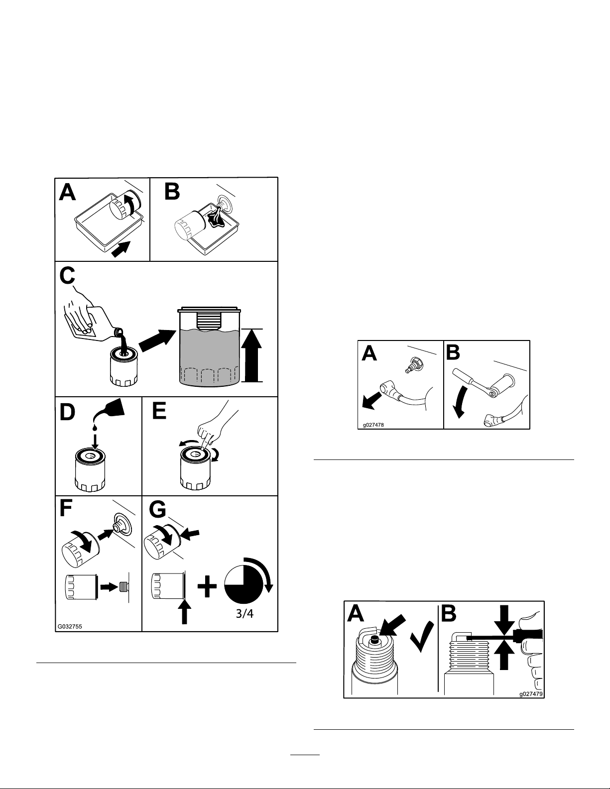
ChangingtheEngine-OilFilter
B
A
g027478
B
A
g027479
ServicingtheSparkPlugs
ServiceInterval:Every200hours
Note:Changetheengineoilltermorefrequentlywhen
operatingconditionsareextremelydustyorsandy.
1.Draintheoilfromtheengine;refertoChangingthe
EngineOil(page34).
2.Changetheengineoillter(Figure34).
Note:Allow2minutesforthenewoiltobeabsorbed
bythenewltermaterial.
ServiceInterval:Every200hours—Checkandgapthe
sparkplug(EFIenginesonly).
Every500hours—Checkandgapthesparkplug
(Non-EFIenginesonly).
Makesurethattheairgapbetweenthecenterandside
electrodesiscorrectbeforeinstallingthesparkplugs.Usea
spark-plugwrenchforremovingandinstallingthesparkplugs
andagappingtool/feelergaugetocheckandadjusttheair
gap.Installnewsparkplugsifnecessary.
TypeforEFIengines:Champion
TypeforNon-EFIengines:Champion
equivalent
AirGap:0.76mm(0.030inch)
®
XC12YCorequivalent
®
RC12YCor
RemovingtheSparkPlugs
1.Movethespeed-controllevertotheNEUTRALposition
tostopthemachine.
2.DisengagethePTO,engagetheparkingbrake,shutoff
theengine,andwaitforallmovingpartstostop.
3.Removethesparkplugs.
Figure34
Note:Ensuretheoilltergaskettouchestheengine
andthenanextra3/4turniscompleted.
3.Fillthecrankcasewiththepropertypeofnewoil;refer
toCheckingtheEngine-OilLevel(page33).
Figure35
CheckingtheSparkPlugs
Important:Replacethesparkplugswhentheyhave:a
blackcoating,wornelectrodes,anoilylm,cracksor
reuseisquestionable.
Ifyouseelightbrownorgrayontheinsulator,theengineis
operatingproperly .Ablackcoatingontheinsulatorusually
meansthattheaircleanerisdirty.
Setthegapto0.76mm(0.030inch).
Figure36
35
Page 36

InstallingtheSparkPlugs
Tightenthesparkplugsto24.4to29.8N∙m(18to22ft-lb).
FuelSystem
Maintenance
WARNING
Fuelsystemcomponentsareunderhighpressure.
Theuseofimpropercomponentscanresultin
systemfailure,gasolineleakage,andpossible
explosion.
Useonlyapprovedfuellinesandfuellters.
ServicingtheElectronic Fuel-InjectionSystem
Thismachinecontainsanelectronicfuel-injectionsystem.It
controlsthefuelowunderdifferentoperatingconditions.
Figure37
CheckingtheSparkArrester
ForaModelwithaSparkArrester
ServiceInterval:Every50hours
WARNING
Hotexhaustsystemcomponentsmayignite
gasolinevaporsevenyoushutofftheengine.Hot
particlesexhaustedduringengineoperationmay
igniteammablematerials.Firemayresultin
personalinjuryorpropertydamage.
Donotrefuelorruntheengineunlessaspark
arresterisinstalled.
1.Shutofftheengine,waitforallmovingpartstostop,
andremovethekey.Engagetheparkingbrake.
2.Waitforthemufertocool.
3.Ifthereareanybreaksinthescreenorwelds,replace
thearrester.
4.Ifthescreenisplugged,removethearresterand
shakethelooseparticlesoutofthearresterandclean
thescreenwithawirebrush(soakitinsolventif
necessary).Installthearresterontheexhaustoutlet.
Theelectroniccontrolunit(ECU)continuouslymonitorsthe
operationoftheEFIsystem.
Ifaproblemorfaultwithinthesystemisdetected,the
malfunctionindicatorlight(MIL)illuminates.TheMIListhe
redlightlocatedintherightconsolepanel.
OncetheMILilluminates,makeinitialtroubleshooting
checks.RefertotheMILsectionunderTroubleshooting
(page58).
Ifthesechecksdonotcorrecttheproblem,furtherdiagnosis
andservicingbyanAuthorizedServiceDealerisnecessary.
ReplacingtheFuelFilter
ServiceInterval:Every200hours/Yearly(whichevercomes
rst)(moreoftenindirtyordusty
conditions).
Thefuellterislocatedneartheengineonthefrontorrear
sideoftheengine.
1.Movethespeed-controllevertotheNEUTRALposition
tostopthemachine.
2.DisengagethePTO,engagetheparkingbrake,shutoff
theengine,andwaitforallmovingpartstostop.
3.Waitforthemachinetocooldown.
4.Closethefuel-shutoffvalveundertheseat(Figure13).
5.Squeezetheendsofthehoseclampstogetherandslide
themawayfromthelter(Figure38).
36
Page 37
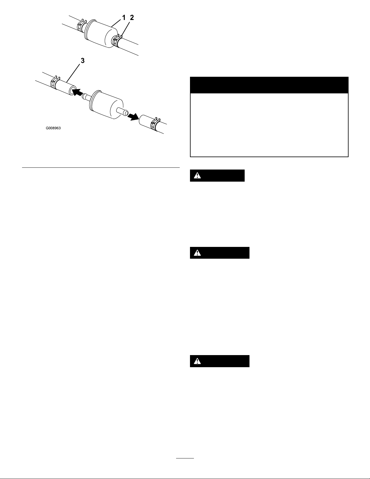
G008963
12
3
1.Fuellter
2.Hoseclamp
Figure38
3.Fuelline
ElectricalSystem
Maintenance
ServicingtheBattery
ServiceInterval:Monthly
WARNING
CALIFORNIA
Proposition65Warning
Batteryposts,terminals,andrelated
accessoriescontainleadandleadcompounds,
chemicalsknowntotheStateofCalifornia
tocausecancerandreproductiveharm.
W ash hands after handling .
6.Removethelterfromthefuellines.
7.Installanewlterandmovethehoseclampscloseto
thelter(Figure38).
8.Openthefuel-shutoffvalve.
Note:Installthefuel-linehosesandsecurethemwithplastic
tiesthesameastheywereoriginallyinstalledatthefactoryto
keepthefuellineawayfromcomponentsthatcouldcause
fuellinedamage.
ServicingtheFuelTank
Donotattempttodrainthefueltank.Ensurethatan
AuthorizedServiceDealerdrainsthefueltank.
DANGER
Batteryelectrolytecontainssulfuricacidwhichisa
deadlypoisonandcausessevereburns.
Donotdrinkelectrolyteandavoidcontactwith
skin,eyesorclothing.Wearsafetyglassestoshield
youreyesandrubberglovestoprotectyourhands.
RemovingtheBattery
WARNING
Batteryterminalsormetaltoolscouldshortagainst
metalmachinecomponentscausingsparks.Sparks
cancausethebatterygasestoexplode,resulting
inpersonalinjury.
•Whenremovingorinstallingthebattery,donot
allowthebatteryterminalstotouchanymetal
partsofthemachine.
•Donotallowmetaltoolstoshortbetween
thebatteryterminalsandmetalpartsofthe
machine.
37
WARNING
Incorrectbatterycableroutingcoulddamagethe
machineandcables,causingsparks.Sparkscan
causethebatterygasestoexplode,resultingin
personalinjury.
•Alwaysdisconnectthenegative(black)battery
cablebeforedisconnectingthepositive(red)
cable.
•Alwaysconnectthepositive(red)batterycable
beforereconnectingthenegative(black)cable.
Page 38
1.Movethespeed-controllevertotheNEUTRALposition
tostopthemachine.
ChargingtheBattery
2.DisengagethePTO,engagetheparkingbrake,shutoff
theengine,andwaitforallmovingpartstostop.
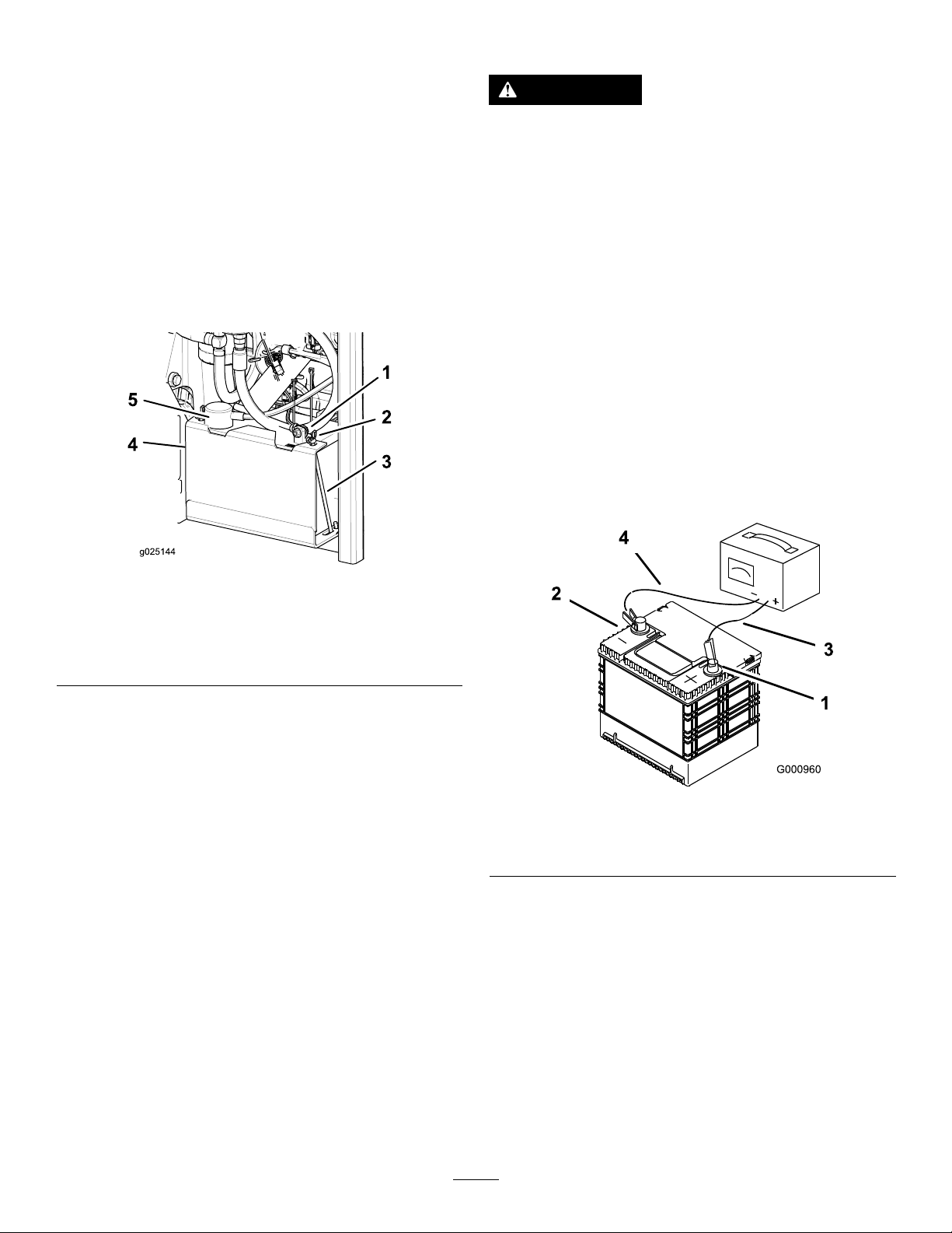
3.Disconnectthenegativebatterycable(black)fromthe
negative(-)(black)batteryterminal(Figure39).
4.Slidetheredterminalbootoffthepositive(red)battery
terminalandremovethepositive(+)(red)batterycable
(Figure39).
5.RemovethewingnutssecuringtheJ-hooks(Figure39).
6.Removetheclamp(Figure39).
7.Removethebattery.
WARNING
Chargingthebatteryproducesgasesthatcan
explode.
Neversmokenearthebatteryandkeepsparksand
amesawayfrombattery.
Important:Alwayskeepthebatteryfullycharged
(1.265specicgravity).Thisisespeciallyimportantto
preventbatterydamagewhenthetemperatureisbelow
0°C(32°F).
1.Chargebatteryfor10to15minutesat25to30Aor
30minutesat10A.
2.Whenthebatteryisfullycharged,unplugthecharger
fromtheelectricaloutlet;thendisconnectthecharger
leadsfromthebatteryposts(Figure40).
3.Installthebatteryinthemachineandconnectthe
batterycables,refertoInstallingtheBattery(page38).
Note:Donotrunthemachinewiththebattery
disconnected;electricaldamagemayoccur.
Figure39
1.Negative(black)battery
cable
2.Wingnut
3.J-hook
4.Clamp
5.Positive(red)batterycable
InstallingtheBattery
1.Positionthebatteryinthetraywiththeterminalposts
oppositefromthehydraulictank(Figure39).
2.Installthepositive(red)batterycabletothepositive
(+)batteryterminal.
3.Installthenegative(black)batterycableandground
wiretothenegative(-)batteryterminal.
4.Securethecableswith2bolts,2washers,and2locknuts
(Figure39).
5.Slidetheredterminalbootontothepositive(red)
batterypost.
6.Installtheclampandsecureitwiththewingnutsand
J-hooks(Figure39).
1.Positivebatterypost
2.Negativebatterypost
Figure40
3.Red(+)chargerlead
4.Black(-)chargerlead
38
Page 39

ServicingtheFuses
Theelectricalsystemisprotectedbyfuses.Itrequires
nomaintenance;however,ifafuseblowscheckthe
component/circuitforamalfunctionorshort.
1.Thefusesarelocatedonrightsidebehindtheseat.
2.Toreplacethefuses,pulloutonthefusetoremoveit.
3.Installanewfuse.
Note:Useproperlysizedjumpercableswithshort
lengthstoreducevoltagedropbetweensystems.Make
surethatthecablesarecolorcodedorlabeledforthe
correctpolarity.
CAUTION
Connectingthejumpercablesincorrectly
(wrongpolarity)canimmediatelydamagethe
EFIsystem.
AdjustingtheSafetySwitches
Adjustallsafetyswitchessothattheplungerextends4.8mm
to6.4mm(3/16inchto1/4inch)fromtheswitchbody
whentheplungeriscompressed(Figure41).
Figure41
1.4.8to6.4mm(3/16to1/4inch)
Jump-StartingtheMachine
1.Checkandcleancorrosionfromthebatteryterminals
beforejump-starting.
Becertainofbatteryterminalpolarityand
jumpercablepolaritywhenhookingup
batteries.
WARNING
Batteriescontainacidandproduceexplosive
gases.
•Shieldtheeyesandfacefromthebatteries
atalltimes.
•Donotleanoverthebatteries.
Note:Besurethattheventcapsaretightandlevel.
Placeadampcloth,ifavailable,overanyventcaps
onbothbatteries.Besurethatthevehiclesdonot
touchandthatbothelectricalsystemsareoffandatthe
sameratedsystemvoltage.Theseinstructionsarefor
negativegroundsystemsonly.
3.Connectthepositive(+)cabletothepositive(+)
terminalofthedischargedbatterythatiswiredtothe
starterorsolenoidasshowninFigure42.
Note:Ensurethattheconnectionsaretight.
CAUTION
Corrosionorlooseconnectionscancause
unwantedelectricalvoltagespikesatanytime
duringthejump-startingprocedure.
Donotattempttojump-startthemachine
withlooseorcorrodedbatteryterminals,or
damagetotheengineorEFImayoccur.
DANGER
Jump-startingaweakbatterythatiscracked,
frozen,hasalowelectrolytelevel,orhas
anopen/shortedbatterycellcancausean
explosion,resultinginseriouspersonalinjury.
Donotjump-startaweakbatteryifthese
conditionsexist.
2.Makesurethattheboosterbatteryisagoodandfully
chargedlead-acidbatteryat12.6Vorgreater.
Figure42
1.Positive(+)cableon
dischargedbattery
2.Positive(+)cableon
boosterbattery
3.Negative(–)cableonthe
boosterbattery
4.Negative(–)cableonthe
engineblock
4.Connecttheotherendofthepositivecabletothe
positiveterminaloftheboosterbattery.
5.Boosterbattery
6.Dischargedbattery
7.Engineblock
39
Page 40
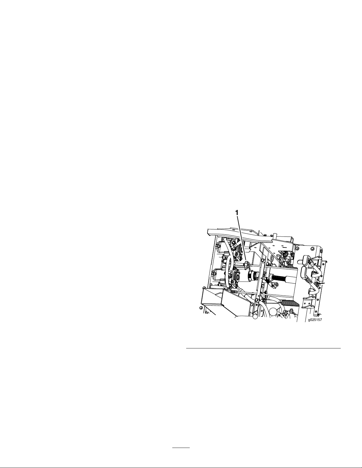
5.Connecttheblacknegative(–)cabletotheother
g025157
terminal(negative)oftheboosterbattery.
DriveSystem
6.Makethenalconnectionontheengineblockofthe
stalledvehicle(nottothenegativebatterypost)away
fromthebatteryandstandback.
7.Startthevehicleandremovethecablesinthereverse
orderofconnection.
Important:Disconnecttheengineblock(block)
connectionrst.
Maintenance
AdjustingtheTracking
Note:Thetrackingknobislocatedundertheseat.
Note:Rotatingthisknoballowsnetuningadjustmentsso
thatthemachinetracksstraightwiththedriveleversinthe
fullforwardposition.
1.Runthemachineat3/4speedforatleast5minutesto
bringhydraulicuiduptooperatingtemperature.Stop
machineandwaitforallmovingpartstostop.
2.Engagetheparkingbrake.
3.Tilttheseatforwardtogainaccesstothetrackingknob.
4.Rotatetheknobtowardtherighttosteerrightand
rotateittowardthelefttosteerleft.
5.Adjustin1/8turnincrementsuntilthemachinetracks
straight.
6.Checkandensurethatthemachinedoesnotcreep
wheninneutralwiththeparkingbrakesdisengaged
(Figure43).
Figure43
1.Trackingknob
CheckingtheTirePressure
ServiceInterval:Every40hours
Maintaintheairpressureinthereartiresat103kPa(15psi).
Uneventirepressurecancauseunevencut.Checkthetires
whentheyarecold,togetthemostaccuratepressurereading.
Note:Thefronttiresaresemi-pneumatictiresanddoesnot
requireairpressuremaintenance.
40
Page 41
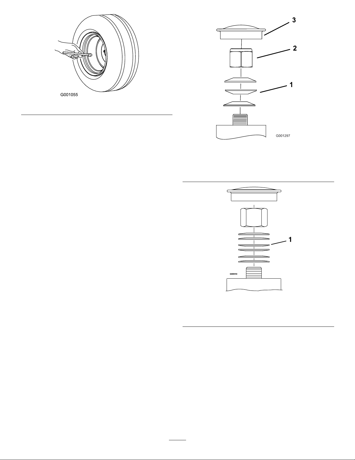
Figure44
Note:Donotaddanytypeoftirelinerorfoamllmaterial
tothetires.
CheckingtheWheel-LugNuts
Figure45
FrontCaster
ServiceInterval:Aftertherst100hours
Every500hours
Checkandtorquethewheel-lugnutsto122to129N∙m(90
to95ft-lb).
CheckingtheWheel-HubNuts
ServiceInterval:Aftertherst100hours
Every500hours
Checkandensurethatthetorqueoftheslottednutis373to
475N∙m(275to350ft-lb).
AdjustingtheCaster-Pivot Bearings
ServiceInterval:Every500hours/Yearly(whichevercomes
rst)
1.Movethespeed-controllevertotheNEUTRALposition
tostopthemachine.
1.Springwashers
2.Locknut
1.Springwashers
3.Dustcap
Figure46
RearCaster
2.DisengagethePTO,engagetheparkingbrake,shutoff
theengine,andwaitforallmovingpartstostop.
3.Removethedustcapfromthecasterandtightenthe
locknut(Figure45andFigure46).
4.Tightenthelocknutuntilthespringwashersareat
andthenbackoff1/4turntoproperlysetthepre-load
onthebearings(Figure45andFigure46).
Important:Makesurethatthespringwashers
areinstalledcorrectlyasshowninFigure45and
Figure46.
5.Installthedustcap.
41
Page 42

CoolingSystem
Maintenance
CheckingandCleaningthe HydraulicPumps
ServiceInterval:Beforeeachuseordaily
CleaningtheEngineScreen andEngineOilCooler
ServiceInterval:Beforeeachuseordaily
Removeanybuildupofgrass,dirt,orotherdebrisfromthe
oilcooler.
Beforeeachuseremoveanybuildupofgrass,dirt,orother
debrisfromtheenginescreen.Thishelpsensureadequate
coolingandcorrectenginespeedandreducesthepossibility
ofoverheatingandmechanicaldamagetotheengine.
ServicingtheEngine-Oil Cooler
ServiceInterval:Every100hours
1.Movethespeed-controllevertotheNEUTRALposition
tostopthemachine.
2.DisengagethePTO,engagetheparkingbrake,shutoff
theengine,andwaitforallmovingpartstostop.
3.Removethefuel-tankmountingnutsandswingout
thefueltank.
1.Movethespeed-controllevertotheNEUTRALposition
tostopthemachine.
2.DisengagethePTO,engagetheparkingbrake,shutoff
theengine,andwaitforallmovingpartstostop.
3.Raisetheseat.
4.Cleanthedebrisandgrassfromthehydraulicpumps.
5.Lowertheseat.
4.Keeptheoilcoolerfreeofdebrisbycleaningthens
withabrush.
5.Swingthefueltankinandsecureitwiththemounting
nuts.
6.Backthemountingnutsoff1/2turntoallowfortank
expansion.
CleaningtheEngineCooling FinsandShrouds
ServiceInterval:Every100hours/Yearly(whichevercomes
rst)
1.Movethespeed-controllevertotheNEUTRALposition
tostopthemachine.
2.DisengagethePTO,engagetheparkingbrake,shutoff
theengine,andwaitforallmovingpartstostop.
3.Removetheair-intakescreenandfanhousing.
4.Cleanthedebrisandgrassfromtheengineparts.
5.Installair-intakescreenandfanhousing.
42
Page 43

BrakeMaintenance
AdjustingtheParkingBrake
ServiceInterval:Aftertherst100hours
Every500hoursthereafter
Makesurethatthebrakeisadjustedproperly.Followthis
procedurewhenyouremoveorreplaceabrakecomponent.
1.Stopthemachineandmovethespeed-controllever
totheNEUTRALposition.
2.DisengagethePTO,engagetheparkingbrake,shutoff
theengine,andwaitforallmovingpartstostop.
3.Releasetheparkingbrake.
4.Tilttheseatforward.
5.Checkandensurethereisnoslackbetweenthe
parking-brakehandleandthelinkage.
6.Ifanadjustmentisnecessary,removetheclevispinand
rotatethelinkagecounterclockwisetolengthenitor
clockwisetoshortenit.
Figure48
Figure47
1.Parkingbrake
2.Rotateyoke
3.Clevispin
4.Speed-controllever
5.Steeringlevers
7.Measurethecompressedspringlengthonbothvertical
springassemblies.
1.Parkingbrake4.Verticalspringassembly
2.Steeringlever
3.Speed-controllever6.6to7cm(2.35to2.85
5.Nut
inches)
8.Adjustthelinkagelengthwiththe2nutsatthebottom
oftheverticalspringassembly(Figure49).
Note:Thelinkageshouldmeasure22.7to23.3cm
(8.92to9.16inches).
Note:Thespringshouldmeasurebetween6to7cm
(2.35to2.85inches).Ifnecessary,adjustthenutat
thetopoftheverticalspringassemblytoachievethis
distance.
1.22.7to23.3cm(8.92to
9.16inches)
43
Figure49
2.Nuts
Page 44

9.Engageanddisengagethebrakestocheckforproper
engagementanddisengagement.Adjustifnecessary.
BeltMaintenance
Note:Whenthebrakesaredisengaged,thereshould
belittletonofreeplayinthebrakelinkagewithno
dragginginthebrakes.
InspectingtheBelts
ServiceInterval:Every40hours
1.Stopthemachineandmovethespeed-controllever
totheNEUTRALposition.
2.DisengagethePTO,engagetheparkingbrake,shutoff
theengine,andwaitforallmovingpartstostop.
3.TiltthehopperupandcheckthepumpandPTOdrive
beltsforwear,cracking,orcontamination.
Note:Thebeltsarespringtensionedandno
adjustmentisnecessaryunlessthebeltsarereplaced.
ReplacingthePTOBelts
1.Stopthemachineandmovethespeed-controllever
totheNEUTRALposition.
2.DisengagethePTO,engagetheparkingbrake,shutoff
theengine,andwaitforallmovingpartstostop.
3.Withtheengineoff,engagethePTOlever,then
removethehairpincotterandclevispinatthebottom
ofthePTO-brakeband.
4.Rotatethebrakebandupwardandoutofthewayof
thebeltskeepingclearofthebeltdrive.
5.DisengagethePTOlever.
6.LoosenbeltguidesAandB(Figure50).
7.Removethebelts.
8.Routethenewbeltsontothepulleysasshownin
Figure50.
Figure50
1.Idler5.Engine
2.BeltguideB6.BeltguideA
3.PTObelt
4.Jackshaft
9.EngagethePTOlever.
10.Rotatethebrakebanddownintotheoriginalposition.
11.Installtheclevispinandhairpincottertosecurethe
brakeband.
12.EngagethePTOlever.
44
7.Blower
Page 45

13.Loosenthejamnutsandadjustthelinkageuntilthe
topoftheidlerarmisalignedwiththebottomofthe
notchonthetensionarmasshowninFigure51.
Figure51
Figure52
1.Pump-drivebelt4.Pump
2.Pump5.Idler
3.Idler6.Engine
7.InstallthePTObelts;refertoReplacingthePTOBelts
(page44).
1.Tensionarm
2.Loosenthejamnuts.
3.WhenPTOisengaged,aligntopofidlerarmwithbottomof
notchontensionarm,asshown.
4.Idlerarm
14.TightenthejamnutsanddisengagethePTOlever.
15.EngagethePTOleverandcheckthealignment.
16.CheckandadjustthebeltguidesasstatedinAdjusting
theBeltGuides(page45).
ReplacingthePump-DriveBelt
1.Stopthemachineandmovethespeed-controllever
totheNEUTRALposition.
2.DisengagethePTO,engagetheparkingbrake,shutoff
theengine,andwaitforallmovingpartstostop.
3.RemovethePTOBelts;refertoReplacingthePTO
Belts(page44).
4.Pullthespringidlerorremovethespringtorelievethe
tensionofthepump-drivebelt.
5.Removetheoldbelt.
6.Routethenewbeltontothesheavesasshowninthe
decallocatedonthebackoftheleftdriveshield(Figure
52).
AdjustingtheBeltGuides
1.Stopthemachineandmovethespeed-controllever
totheNEUTRALposition.
2.DisengagethePTO,engagetheparkingbrake,shutoff
theengine,andwaitforallmovingpartstostop.
3.Withtheengineoff,engagethePTOlever.
4.AdjustthebeltguidesasshowninFigure53.
Figure53
1.3mm(1/8inch)4.Rotatethewireformguide
tothecenterbeltsinthe
guide.
2.11mm(7/16inch)5.6mm(1/4inch)
3.3mm(1/8inch)clearance6.8mm(5/16inch)
45
Page 46

ControlsSystem
Maintenance
G.Installtheseatframeassembly,ifremovedin
stepA.
AdjustingtheSpeed-Control
AdjustingtheReverse-Stop Rod
1.Stopthemachineandmovethespeed-controllever
totheNEUTRALposition.
2.DisengagethePTO,engagetheparkingbrake,shutoff
theengine,andwaitforallmovingpartstostop.
3.Checkthemovementofthesteeringleversasfollows:
•Iftheleversmoveslightlyforwardupto3mm
(1/8inch)thennoadjustmentisnecessary.
•Iftheleversdonotmove,thenproceedwiththe
followingsteps:
A.Fliptheseatuporremovetheseat-frame
assembly(withtheseatattached)toobtain
aclearviewofthesteering-controlshaftto
completethisadjustment.
B.Placethespeed-controlleverintheNEUTRAL
position.
C.Releasetheparkingbrake.
D.Slightlyadjustthelengthoftherodby
looseningthejamnutandbyrotatingtherod.
LeverTension
1.Stopthemachineandmovethespeed-controllever
totheNEUTRALposition.
2.DisengagethePTO,engagetheparkingbrake,shutoff
theengine,andwaitforallmovingpartstostop.
3.Toadjustthetension,adjustthepivotnut,whichis
locatedattheendofthemotion-controlshaftinfront
oftherightconsole(Figure55).
Note:Setthetensionhighenoughthatthe
speed-controlleverpositionismaintainedduring
operationandlooseenoughtobemovedcomfortably.
1.Parkingbrake
2.Nut
3.Steeringlever
Figure54
4.Speed-controllever
5.Clevispinandstoprod
E.Engagetheparkingbrakeandcheckthe
steeringlevers.
F.RepeatstepsCthroughEuntilyouachieve
upto3mm(1/8inch)movement.
Figure55
1.Pivotnut4.Frictiondisc
2.Spring-discwashers5.Speed-controlfriction
3.Speed-controlfriction
plate
bracket
6.Speed-controllever
AdjustingtheSpeed-Control Linkage
WARNING
Theenginemustberunningandthedrivewheels
mustbeturningtoadjustthemotioncontrols.
Contactwithmovingpartsorhotsurfacesmay
causepersonalinjury.
Keepyourngers,hands,andclothingclearof
rotatingcomponentsandhotsurfaces.
46
Page 47

CAUTION
Raisingthemowerdeckforserviceormaintenance
relyingsolelyonmechanicalorhydraulicjacks
couldbedangerous.Themechanicalorhydraulic
jacksmaynotbeenoughsupportormay
malfunctionallowingtheunittofall,whichcould
causeinjury.
Donotrelysolelyonmechanicalorhydraulicjacks
forsupport.Useadequatejackstandsorequivalent
support.
1.Stopthemachineandmovethespeed-controllever
totheNEUTRALposition.
2.DisengagethePTO,engagetheparkingbrake,shutoff
theengine,andwaitforallmovingpartstostop.
Figure56
3.Removetheelectricalconnectionfromtheseatsafety
switch,locateddirectlyinfrontoftheseat-switch
assembly.
4.Raisetheframeandplaceonjackstandssothatdrive
wheelscanrotatefreely.
Note:Youmustmaketheneutraladjustmentwith
thedrivewheelsturning.
5.Temporarilyinstallajumperwireacrosstheterminals
intheconnectorofthewiringharness.
6.Starttheengine.
7.Runthemachineatleast5minuteswiththe
speed-controlleveratfullforwardspeedtobringthe
hydraulicsystemoiluptooperatingtemperature.
8.Returnthespeed-controllevertotheNEUTRAL
position.
9.ToobtaintheNEUTRALposition,adjusttheleftand
rightpump-control-rodlinkagesthatconnectthe
steeringcontroltothepump-controlarmsuntilthe
wheelsstoporcreepslightlyinreverse(Figure56).
10.Adjusttheleftpumplinkagebyrotatingthe
tracking-adjustmentknob.
11.Adjusttherightpumplinkagebyusingawrenchto
turnthedoublenutsontheassembly(Figure56)
1.Rotatethetrackingknob
onleftside.
12.Movethesteeringleverstothereverseposition.While
applyingslightpressuretothelevers,allowthesteering
leverstoreturntoNEUTRAL.
Note:Thewheelsmuststopturningorslightlycreep
inreverse.
13.Shutofftheengineandwaitforallmovingpartsto
stop.
14.Removethejumperwirefromthewire-harness
connectorandplugtheconnectorintotheseatswitch.
15.Lowerthemachinefromthejackstands.
2.Rotatethedoublenutson
rightside.
AligningthePTO-DrivePulley
AlignthePTO-drivepulleyforanyofthefollowing
conditions:
•Theblowerhasbeenremovedorreplaced.
•Theenginemountingboltshavebeenloosenedorthe
enginehasbeenmovedorreplaced.
•Thejackshaftmountingboltshavebeenloosenedorthe
jackshafthasbeenmovedorreplaced.
1.Stopthemachineandmovethespeed-controllever
totheNEUTRALposition.
2.DisengagethePTO,engagetheparkingbrake,shutoff
theengine,andwaitforallmovingpartstostop.
3.Removethefuel-tankmountingnutsandswingout
thefueltank.
4.Verifythattheblowerisinstalledandtightlysecured.
5.Loosenthe4enginemountingbolts.
6.Unhookthepump-belttensionspring.
7.Loosenthe4jackshaftmountingbolts.
8.Measuringfromtheblowerpulleyasabaseline,move
theengineandjackshaftuntiltherearsurfaceofall3
47
Page 48
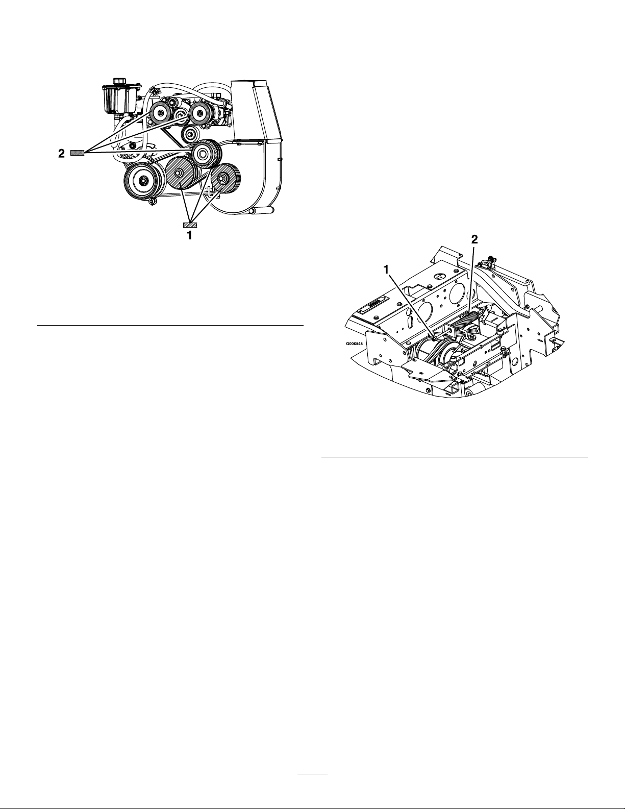
pulleysarealignedwithin0.8to1.6mm(1/32inch
to1/16inch)(Figure57).
Note:Useastraightedgetoalignall3surfaces.
Figure57
AdjustingthePTOBrake Spring
AdjustthePTObrakespringonlyiftheblowerhasbeen
removedorreplacedorifthePTOdriveidlerarmhasbeen
disassembled.
1.Stopthemachineandmovethespeed-controllever
totheNEUTRALposition.
2.DisengagethePTO,engagetheparkingbrake,shutoff
theengine,andwaitforallmovingpartstostop.
3.Locatethebrakespringandthreadthe2jamnutsout
totheendofthebrake-springrod(Figure58).
4.Tightenthejamnutstogetheratendofthebrake-spring
rod.
1.Alignthe3pump-drive
pulleysurfacesshown
withthispatternwithin0.8
to1.6mm(1/32inchto
1/16inch).
9.Tightenthe4enginemountingboltsand4jackshaft
mountingbolts.Checkthealignmentaftertightening.
10.Installthepump-belttensionspring.
11.Swingthefueltankinandinstallthetankmounting
nuts.
12.Alignthepump-drivepulley;AligningthePump-Drive
Pulley(page48).
2.Alignthe3PTO-drive
pulleysurfacesshown
withthispatternwithin0.8
to1.6mm(1/32inchto
1/16inch).
AligningthePump-Drive Pulley
Thepump-drive-pulleyalignmentisnecessaryforanyofthe
followingconditions:
•Theenginemountingboltshavebeenloosenedorthe
enginehasbeenmovedorreplaced.
•Thepumppulleyshavebeenloosened,moved,or
replaced.
•ThePTOpulleyhasbeenaligned;refertoAligningthe
PTO-DrivePulley(page47).
1.Shutoffthemachineandmovethespeed-controllever
totheNEUTRALposition.
2.DisengagethePTO,engagetheparkingbrake,shutoff
theengine,andwaitforallmovingpartstostop.
3.Loosenthesetscrewsonbothpumppulleys.
Figure58
1.Tightenthejamnutshere.
2.PTObrake-springassembly
AdjustingtheHopperDoor
1.Stopthemachineandmovethespeed-controllever
totheNEUTRALposition.
2.DisengagethePTO,engagetheparkingbrake,shutoff
theengine,andwaitforallmovingpartstostop.
3.Loosenthe6doorhingenuts(Figure59).
4.Openthedoorandplacea3/8inch(9.5mm)rubber
stripor3/8inch(9.5mm)diameterhosebetweenthe
hopperandthehopperdoor(Figure59).
5.Closethedoorandpushittightagainstthehopper.
6.Tightenthehingehardware.
7.Openthehopperdoorandremovetherubberstrip.
4.Usingastraightedge,aligneachpumppulleywiththe
enginepulleybyslidingitalongthepumpshaft(Figure
57).
5.Tightenthepulleysetscrewsandcheckthealignment.
48
Page 49

HydraulicSystem
Maintenance
ServicingtheHydraulic System
Figure59
1.Loosenthedoorhinge
nuts—3perside.
2.Placeapieceof9.5mm
(3/8inch)rubberonthis
surface.
AdjustingtheLocking-Pin StopontheMowerDeck
1.Slidethemower-decklockingpinsinonbothsidesof
themowerdeckandrotatethemtolockthemower
deckintheoperationposition.
2.Loosenthejamnutandturnthestopscrewclockwise
untilthelockingpinistightandcannotberotatedby
hand(Figure60).
HydraulicFluidType:Toro
oilorMobil
Important:Usetheuidspecied.Otheruidscould
causesystemdamage.
®
115W -50.
®
HYPR-OIL
™
500hydraulic
CheckingtheHydraulicFluid
ServiceInterval:Every40hours—Checkthehydraulicuid
level.
1.Positionthemachineonalevelsurface.
2.Movethespeed-controllevertotheNEUTRALposition
tostopthemachine.
3.DisengagethePTO,engagetheparkingbrake,shutoff
theengine,andwaitforallmovingpartstostop.
4.Waitfortheengineandthehydraulicsystemtocool
for10minutes.
Note:Togetthecorrectreading,checkthehydraulic
uidlevelwhenthemachineiscool.
5.Raisetheseatup.
6.Cleantheareaaroundthedipstickofthe
hydraulic-systemreservoir(Figure61).
Figure60
1.Rotatethestopscrewclockwiseuntilthelockingpinistight,
thenbackoff1/2turn.
2.Loosenthejamnut.
3.Loosenthestopscrewcounterclockwise1/2turnand
tightenthejamnut.
4.Testthelockingpintomakesurethatitslidesfreely .
Adjustifnecessary.
7.Removethedipstickfromthehydraulicreservoir
(Figure61).
8.Wipethedipstickoffandthreadthedipstickintothe
reservoir.
9.Removethedipstickandlookattheend(Figure61).
Iftheoillevelisattheaddmark,slowlypouronly
enoughoilintothehydraulicreservoirtoraisethelevel
tothefullline.
Important:Donotoverllthehydraulicunits
withoil,asdamagemayoccur.Donotrunthe
machinewiththeoilbelowtheaddmark.
10.Installthedipstick.
49
Page 50
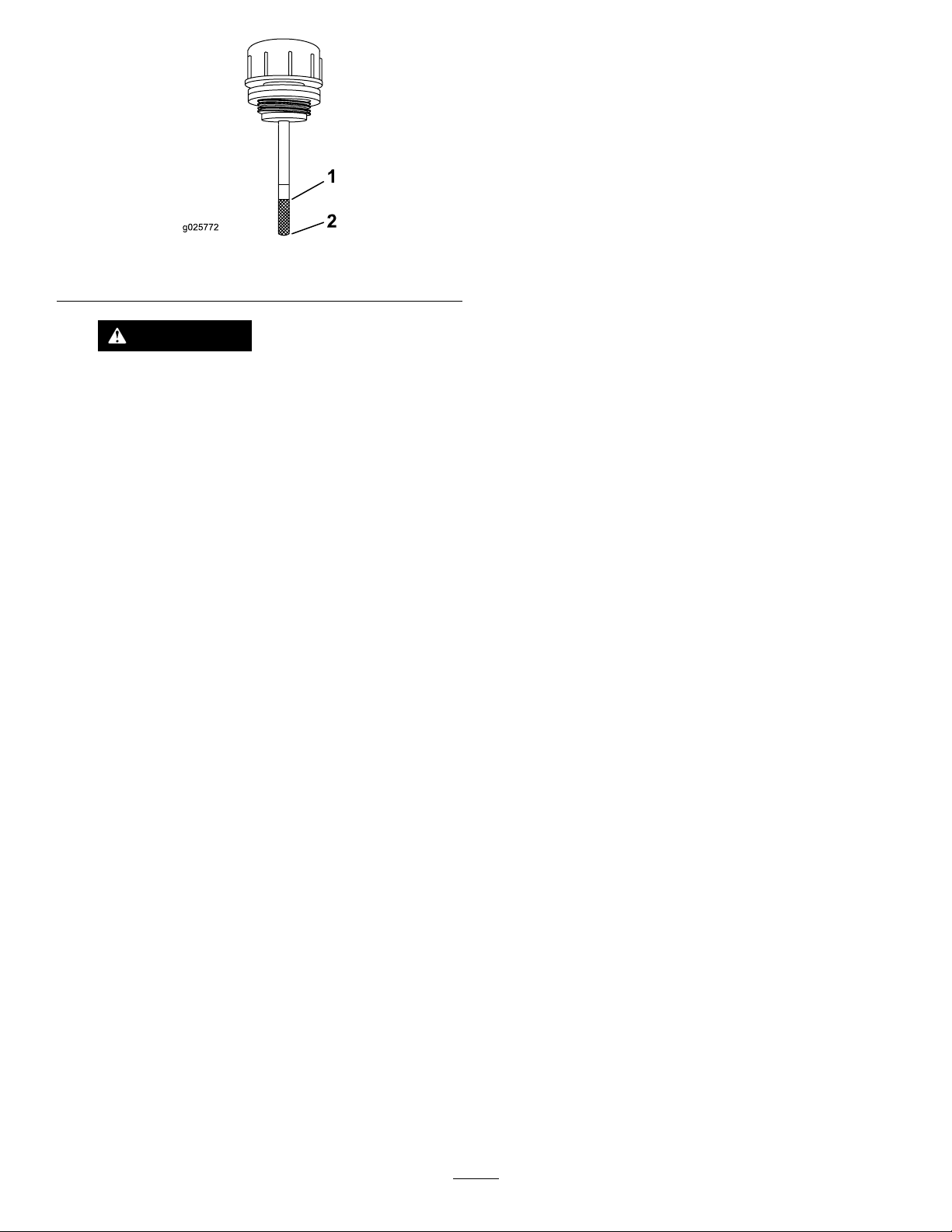
Figure61
1.Full2.Add
WARNING
Hydraulicuidescapingunderpressurecan
penetrateskinandcauseinjury.
•Ifhydraulicuidisinjectedintotheskinit
mustbesurgicallyremovedwithinafew
hoursbyadoctorfamiliarwiththistypeof
injuryorgangrenemayresult.
•Keepyourbodyandhandsawayfrom
pin-holeleaksornozzlesthateject
high-pressurehydraulicuid.
•Usecardboardorpapertondhydraulic
leaks.
•Safelyrelieveallpressureinthehydraulic
systembeforeperforminganyworkonthe
hydraulicsystem.
•Makesurethatallhydraulicuidhoses
andlinesareingoodconditionandall
hydraulicconnectionsandttingsare
tightbeforeapplyingpressuretohydraulic
system.
2.DisengagethePTO,engagetheparkingbrake,shutoff
theengine,andwaitforallmovingpartstostop.
3.Carefullycleantheareaaroundthelter.
Important:Ensurethatnodirtorcontamination
enterthehydraulicsystem.
4.Unscrewandremovethelterandallowtheoilto
drainfromthereservoir.
Important:Donotchangethehydraulicsystem
oil(exceptforwhatcanbedrainedwhenchanging
thelter),unlesstheoilhasbeencontaminatedor
beenextremelyhot.Changingthehydraulicuid
unnecessarilycoulddamagethehydraulicsystem
byintroducingcontaminatesintothesystem.
5.Beforeinstallingthenewlter,llitwithToro
HYPR-OIL
ofoilonthesurfaceoftherubberseal.
6.Turnthelterclockwiseuntiltherubbersealcontacts
thelteradapter,thentightenthelteranadditional
2/3to3/4turn.
7.FillthereservoirasstatedinCheckingtheHydraulic
Fluid(page49).
8.Raisetherearofthemachineupandsupportitwith
jackstands(orequivalentsupport)justhighenoughto
allowdrivewheelstoturnfreely.
9.Starttheengineandmovethethrottlecontroltothe
FULL-THROTTLEposition.
10.Movethespeed-controlleverstothefull-speed
positionandrunthemachineforseveralminutes.
11.Shutoffthemachineandchecktheoillevel.
™
500hydraulicuidandapplyathincoat
®
ReplacingtheHydraulicFilter
ServiceInterval:Aftertherst100hours—Changethe
hydrauliclterandreservoirhydraulic
uidwhenusinganytypeofoil.
Every250hours—Changethehydrauliclterand
reservoirhydraulicuidwhenusingMobil
(moreoftenindirtyordustyconditions).
Every500hours—Changethehydrauliclter
andreservoirhydraulicuidwhenusingT oro
HYPR-OIL
ordustyconditions).
Note:Useasummerlterwhenthetemperatureis0°C
(32°F)andabove.Useawinterlterwhenthetemperatureis
0°C(32°F)andbelow .
1.Movethespeed-controllevertotheNEUTRALposition
tostopthemachine.
™
500hydraulicuid(moreoftenindirty
®
1oil
®
50
Page 51
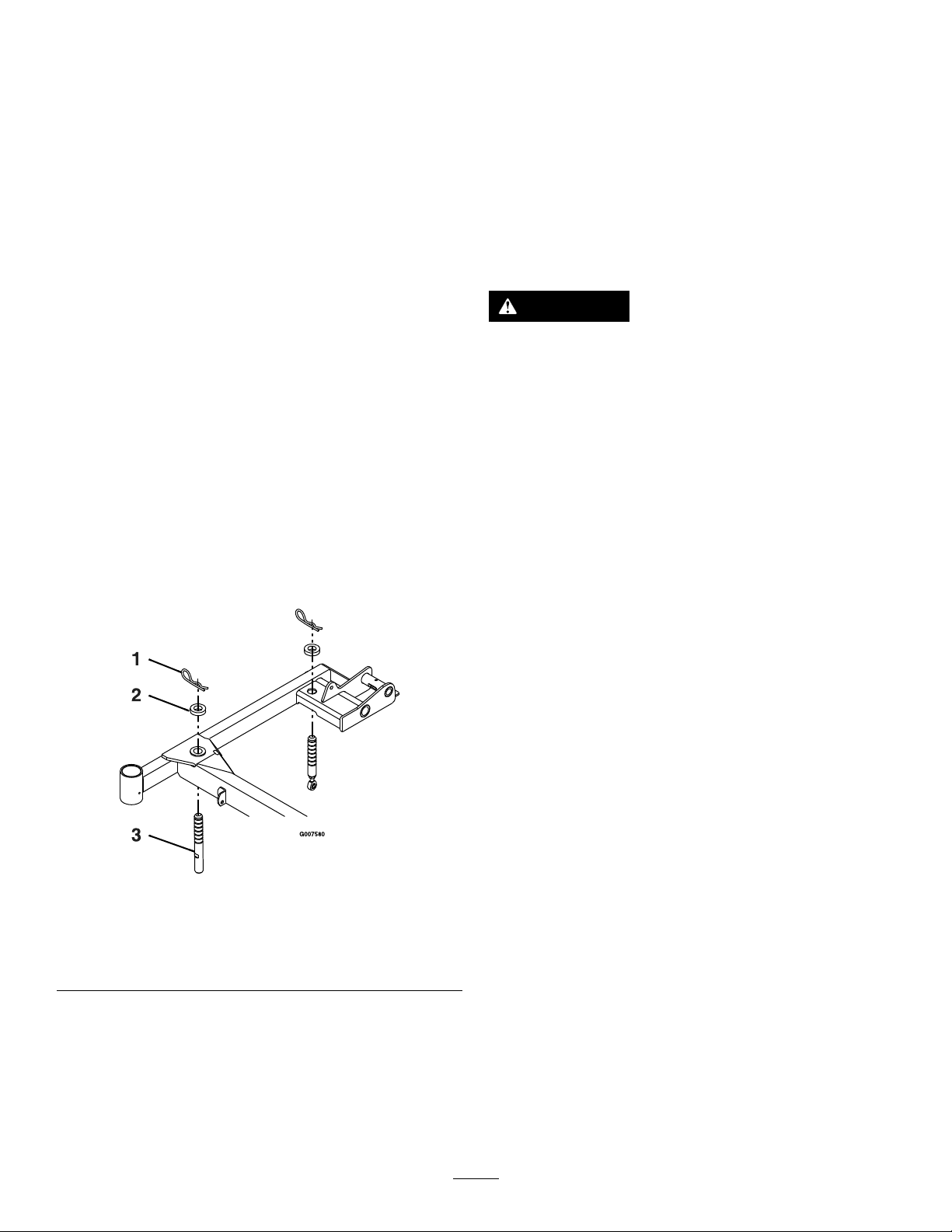
MowerDeck
ServicingtheCuttingBlades
Maintenance
LevelingtheMowerDeck
SettinguptheMachine
Note:Ensurethatthemowerdeckisleveledbefore
matchingtheheightofcut(HOC).
1.Positionthemachineonaatsurface.
2.Movethespeed-controllevertotheNEUTRALposition
tostopthemachine.
3.DisengagethePTO,engagetheparkingbrake,shutoff
theengine,andwaitforallmovingpartstostop.
4.Checkthetirepressureofthedrivetires.Ifneeded,
adjustthepressureto103kPa(15psi).
LevelingtheDeck
1.Stopthemachineandmovethespeed-controllever
totheNEUTRALposition.
2.DisengagethePTO,engagetheparkingbrake,shutoff
theengine,andwaitforallmovingpartstostop.
3.Verifythatallhairpincottersareinthe7.62cm(3inch)
mower-deck-heightholeswiththespacersunderthe
hairpincotters(Figure62).
Maintainsharpbladesthroughoutthecuttingseason,because
sharpbladescutcleanlywithouttearingorshreddingthegrass
blades.Tearingandshreddingturnsgrassbrownattheedges,
whichslowsgrowthandincreasesthechanceofdisease.
Checkthecutterbladesdailyforsharpness,andforany
wearordamage.Filedownanynicksandsharpenthe
bladesasnecessary.Ifabladeisdamagedorworn,replace
itimmediatelywithagenuineT ororeplacementblade.For
convenientsharpeningandreplacement,keepextrablades
onhand.
DANGER
Awornordamagedbladecanbreak,andapiece
ofthebladecouldbethrownatyouorbystanders,
resultinginseriouspersonalinjuryordeath.
•Inspectthebladeperiodicallyforwearor
damage.
•Replaceawornordamagedblade.
BeforeInspectingorServicingthe
Blades
1.Parkthemachineonalevelsurface,disengagethe
blade-controlswitch(PTO),andsettheparkingbrake.
2.TurntheignitionkeytotheOFFposition.
Figure62
RightSideShown
1.Hairpincotter3.Mower-decksupportpin
2.Spacer
4.Shortenorlengtheneachmowerdecksupportpinto
obtainbladetipheightof7.62cm(3inches)atthe
frontofthedeckand8.26cm(31/4inches)attherear
ofthedeck(Figure62).
3.Removethekey.
InspectingtheBlades
ServiceInterval:Beforeeachuseordaily
1.Liftthemowerdeckandsecureitintheraisedposition.
RefertoRaisingtheMowerDeckintotheService
Position(page23).
2.Inspectthecuttingedges(Figure63).
3.Iftheedgesarenotsharporhavenicks,removeand
sharpentheblades.RefertoSharpeningtheBlades
(page53).
4.Inspecttheblades,especiallythecurvedarea(Figure
63).
5.Ifyounoticeanydamage,wear,oraslotformingin
thisarea(Figure63),immediatelyinstallanewblade.
Note:Thefrontpinsarethreadintothemowerdeck
andhaveajamnut.Therearpinshavearodend
threadedintothemwithajamnut.
51
Page 52
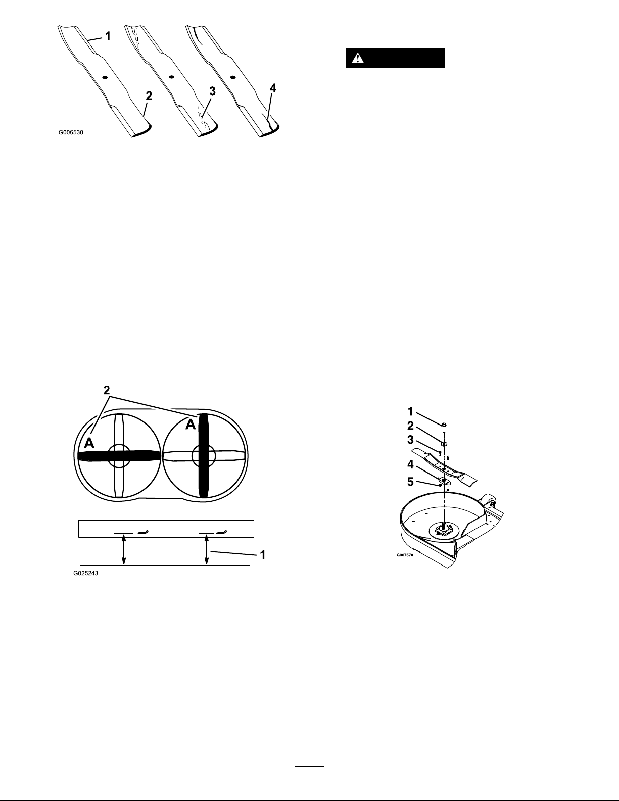
Figure63
G025243
1.Cuttingedge3.Wear/slotforming
2.Curvedarea4.Crack
7.Repeatthepreviousstepsfortheoppositeblade.
WARNING
Abladethatisbentordamagedcouldbreak
apartandcouldseriouslyinjureorkillyouor
bystanders.
•Alwaysreplacebentordamagedblade
withanewblade.
•Neverleorcreatesharpnotchesinthe
edgesorsurfacesofblade.
6.Lowerthemowerdeckintooperatingposition.Refer
toLoweringtheMowerDecktotheOperatingPosition
(page24).
CheckingforBentBlades
1.Movethespeed-controllevertotheNEUTRALposition
tostopthemachine.
2.DisengagethePTO,engagetheparkingbrake,shutoff
theengine,andwaitforallmovingpartstostop.
3.Rotate1bladeasshowninFigure64.
4.Measurefromalevelsurfacetothecuttingedge
atpositionAoftheblade(Figure64).Notethis
dimension.
RemovingtheBlades
Note:Makenoteofthered-coloredbladeposition.From
thenormaluserposition,itislocatedontherightside.
Replaceabladesifithitsasolidobject,isoutofbalance,oris
bent.Toensureoptimumperformanceandcontinuedsafety
conformanceofthemachine,usegenuineTororeplacement
blades.Replacementbladesmadebyothermanufacturers
mayresultinnon-conformancewithsafetystandards.
1.Liftthemowerdeckandsecureintheraisedposition.
RefertoRaisingtheMowerDeckintotheService
Position(page23).
2.Holdthebladeendusingaragorthicklypaddedglove.
3.Removetheblade,washer,andbladeboltthatsecures
thebladeandbladedriver(Figure65).
Figure64
1.Measureherefromblade
tohardsurface.
2.PositionA
5.RotatetheoppositeendofthebladetopositionA.
6.Measurefromalevelsurfacetothecuttingedgeofthe
bladeatthesamepositionasinstep3above.
Note:Thedifferencebetweenthedimensions
obtainedinsteps3and6mustnotexceed1/8inch
(3mm).Ifthisdimensionexceeds1/8inch(3mm),the
bladeisbentandmustbereplaced;refertoRemoving
theBlades(page52)andInstallingtheBlades(page53).
Figure65
1.Bladebolt4.Bladedriver
2.Washer5.Locknuts
3.Shearbolts
4.Removethebladedriverfromtheexistingblade
(Figure65).
52
Page 53
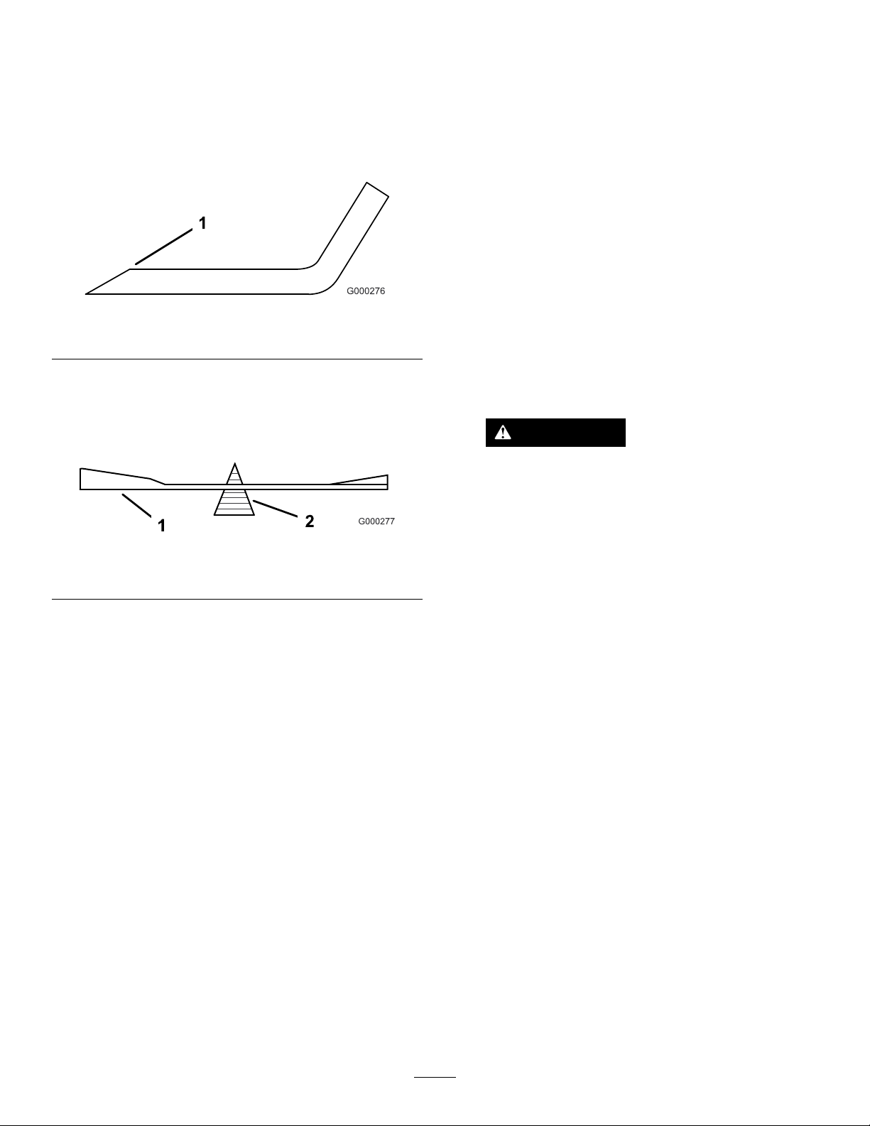
SharpeningtheBlades
InstallingtheBlades
1.Usealetosharpenthecuttingedgeatbothendsof
theblade(Figure66).
Note:Maintaintheoriginalangle.
Note:Thebladeretainsbalanceifyouremovethe
sameamountofmaterialfrombothcuttingedges.
Figure66
1.Sharpenattheoriginalangle
2.Checkthebalanceofthebladebyputtingitonablade
balancer(Figure67).
Note:Ifthebladestaysinahorizontalposition,the
bladeisbalancedandreadytouse.
Figure67
1.Blade2.Balancer
3.Ifthebladeisnotbalanced,lesomemetaloffthe
endofthesailareaonly.
4.Repeatthisprocedureuntilthebladeisbalanced.
Note:Determinetheleftandrightsidesofthemachine
fromthenormaloperatingposition.
Note:Ensurethatyouinstallthered-coloredbladeonthe
rightside.
1.Installthebladedrivertothenewbladeswiththeshear
boltsandlocknuts(Figure65).
2.Torquetheshearboltsto922to1130N∙m(80to100
in-lb).
Note:Aligntheblade-driveratswiththeatsonthe
shaftwheninstallingthebladeonthemowerdeck.
3.Installtheblade,washer,andbladebolttothespindle
shaft(Figure65).
4.Torquethebladeboltto115to149N∙m(85-110ft-lb).
5.Lowerthemowerdecktotheoperatingposition.
RefertoLoweringtheMowerDecktotheOperating
Position(page24).
WARNING
Operatingamowerdeckwithlooseor
weakenedbladeboltscanbedangerous.A
looseorweakenedbladeboltcouldallowa
bladerotatingatahighspeedtocomeout
fromunderthemowerdeck,causingserious
injuryorpropertydamage.
•Replacethebladeboltafterstrikinga
foreignobject.
•UseonlygenuineT ororeplacementparts.
•Donotlubricatethethreadsoftheboltor
spindlebeforeassembly.
53
Page 54

RemovingtheMowerDeck
WARNING
OperatingthismachinewithoutanapprovedT oro
front-mountattachmentincreasesthepossibilityof
operatorentanglementindrivewheelsorforward
tipover.Entanglementortip-overcouldcause
seriousinjuryordeath.
Whenoperatingthismachinewithoutanapproved
Torofront-mountattachment,dothefollowing:
•Keepfeetandclothingawayfromtires.
•Limitoperationtominimumrequiredtoinstall
adifferentfront-mountattachment.
•Minimizespeedanduseextremecaution.
•Onlyoperateonaatlevelsurface.
•Donotoperateupordownatrailerramp.
•Avoidsuddenaccelerationordeceleration.
Important:Donottransportthismachinewithoutan
approvedTorofrontmountattachment.
1.Shutofftheengine,waitforallmovingpartstostop,
andremovethekey.Engagetheparkingbrake.
2.Raisethemowerdeckupandlatchitwiththe
deck-lockingpins.RefertoRaisingtheMowerDeck
intotheServicePosition(page23).
3.Removethehairpincottersandwashersatthetopof
thedeck-lift-assistspringoneachsideofthemachine
(Figure68).
5.Unlatchthemowerdeckfromtheraisedposition
andslowlylowerthemowerdecktoground;referto
LoweringtheMowerDecktotheOperatingPosition
(page24).
Note:Themowerdeckwillbecomeheavieronce
youremovethespringsfromtheanchors.Lowerthe
mowerdeckcarefully.
6.Removethelynchpinsatfrontofpusharmsonboth
sidesofthemachine(Figure69).
Figure69
1.Slidethepusharmintothedeckpush-armtube.
2.Securethepushpinarmwithlynchpin.
7.Removethehairpincotterandclevispinfromboth
sidesofthePTOguard(Figure70).
Figure68
1.Spring-anchorpinunderconsole
2.Securespringswithawasherandhairpincotter.
3.Slidespringontospring-anchorpin.
4.Removethespringfromthespringanchor.Repeatfor
othersideofthemachine.
Figure70
1.SecurethePTOguardwiththeclevispinandhairpincotter.
8.Raisetheseatanddisconnectthedriveshaftusingthe
quickcoupleratthejackshaft(Figure71).
54
Page 55
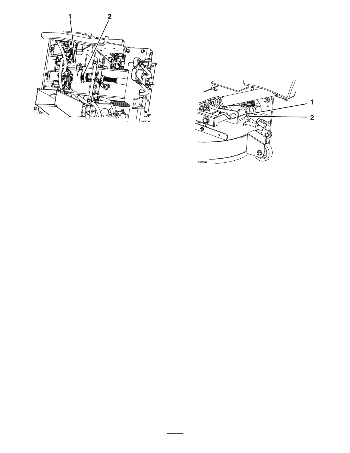
Figure71
1.Jackshaft2.Driveshaft
9.Pullthemowerdeckforwardtoremoveitfromthe
machine.
AdjustingtheLocking-Pin StopontheMowerDeck
1.Slidethemower-decklockingpinsinonbothsidesand
rotatetolockthedeckintheoperationposition.
2.Loosenthejamnutandturnthestopscrewclockwise
untilthelockingpinistightandcannotberotatedby
hand(Figure72).
Figure72
InstallingtheMowerDeck
Important:Donottransportthemachinewithoutan
approvedTorofrontmountattachment.
1.Shutofftheengine,waitforallmovingpartstostop
andremovethekey.Engagetheparkingbrake.
2.Rollthemowerdeckuptothemachinewiththe
dischargetubedown,makingsurethatthedecksprings
arelocatedabovethedrivewheelandbelowthe
consoleoneachside.
3.Raisetheseatandinstallthedriveshaftontothe
jackshaft(Figure71)
4.Alignthemower-deckpush-armtubestothemachine
push-armsandpushthemowerdeckrearward.
5.Securethepusharmswiththelynchpinsontheleft
andrightsidesofthemachine(Figure69).
6.AligntheupperportionoftherubberPTOguardto
thetabsonthefrontoftheconsoleandsecurewitha
clevispinandhairpincotteroneachside(Figure70).
7.Releasethemower-decklockingpinsoneachside,raise
themowerdecktotheserviceposition,andsecure
thedecklatchontohook.RefertoRaisingtheMower
DeckintotheServicePosition(page23).
1.Rotatethestopscrewclockwiseuntillockingpinistight,
thenbackoff1/2turn.
2.Loosenthejamnut
3.Loosenthestopscrewcounterclockwise1/2turnand
tightenthejamnut.
4.Testthelockingpintomakesureitslidesfreely .Adjust
ifnecessary.
8.Installthespringsontothespringanchorpinsunder
theleftandrightconsolesandsecurewithawasher
andhairpincotter(Figure68).
9.Unlatchthemowerdeckfromtheraisedposition,
slowlylowerthemowerdecktoground,andlockthe
deck-lockingpinsoneachside.RefertoLoweringthe
MowerDecktotheOperatingPosition(page24).
55
Page 56

Cleaning
Storage
CleaningundertheMower
ServiceInterval:Beforeeachuseordaily
1.Movethespeed-controllevertotheNEUTRALposition
tostopthemachine.
2.DisengagethePTO ,engagetheparkingbrake,shutthe
engine,andwaitforallmovingpartstostop.
3.Liftthemowerdeckandsecureitintheraisedposition.
RefertoRaisingtheMowerDeckintotheService
Position(page23).
4.Cleananygrassbuildupunderthemowerdeck.
5.Lowerthemowerdecktotheoperatingposition.
RefertoLoweringtheMowerDecktotheOperating
Position(page24).
CleaningDebrisfromthe Machine
ServiceInterval:Beforeeachuseordaily
1.Shutofftheengine,waitforallmovingpartstostop,
andremovethekey.Engagetheparkingbrake.
2.Cleanoffanyoil,debris,orgrassbuilduponthe
machine,especiallyaroundthefueltank,engine,and
exhaustarea.
DisposingofWaste
Engineoil,batteries,hydraulicuid,andenginecoolantare
pollutantstotheenvironment.Disposeoftheseaccordingto
yourstateandlocalregulations.
CleaningandStorage
1.Disengagethepowertakeoff(PTO),settheparking
brake,andturntheignitionkeytotheOFFposition.
Removethekey.
2.Removegrassclippings,dirt,andgrimefromthe
externalpartsoftheentiremachine,especiallythe
engineandhydraulicsystem.Cleandirtandchafffrom
theoutsidetheenginecylinderheadnsandblower
housing.
Important:Youcanwashthemachinewithmild
detergentandwater.Donotpressurewashthe
machine.Avoidexcessiveuseofwater,especially
nearthecontrolpanel,engine,hydraulicpumps,
andmotors.
3.Checkthebrake;refertoAdjustingtheParkingBrake
(page43).
4.Servicetheaircleaner;refertoServicingtheAir
Cleaner(page32).
5.Greasethemachine;refertoLubrication(page30).
6.Changethecrankcaseoil;refertoChangingtheEngine
Oil(page34).
7.Checkthetirepressure;refertoCheckingtheTire
Pressure(page40).
8.Changethehydrauliclters;refertoReplacingthe
HydraulicFilter(page50).
9.Chargethebattery;refertoChargingtheBattery(page
38).
10.Scrapeanyheavybuildupofgrassanddirtfromthe
undersideofthemower,thenwashthemowerwith
agardenhose.
Note:Runthemachinewiththeblade-controlswitch
(PTO)engagedandtheengineathighidlefor2to
5minutesafterwashing.
11.Checktheconditionoftheblades;refertoServicing
theCuttingBlades(page51).
12.Forstorageover30days,preparethemachineas
follows:
A.Addapetroleum-basedstabilizer/conditionerto
fuelinthetank.Followthemixinginstructions
fromthestabilizermanufacturer.Donotusean
alcohol-basedstabilizer(ethanolormethanol).
Note:Afuelstabilizer/conditionerismost
effectivewhenmixedwithfreshfuelandusedat
alltimes.
B.Runtheenginetodistributeconditionedfuel
throughthefuelsystem(5minutes).
C.Shutofftheengine,waitforittocool,anddrain
thefueltank;refertoServicingtheFuelTank
(page37).
56
Page 57

D.Starttheengineandrunituntilitstops.
E.Disposeoffuelproperly .Recycleasperlocal
codes.
Important:Donotstorefuelwith
stabilizer/conditionerover90days.
13.Checkandtightenallbolts,nuts,andscrews.Repairor
replaceanypartthatisdamaged.
14.Paintallscratchedorbaremetalsurfaces.Paintis
availablefromyourAuthorizedServiceDealer.
15.Storethemachineinaclean,drygarageorstoragearea.
Removethekeyfromtheignitionswitchandkeepit
outofreachofchildrenorotherunauthorizedusers.
Coverthemachinetoprotectitandkeepitclean.
57
Page 58

Troubleshooting
Problem
Themalfunctionindicatorlight(MIL)
comeson.
Thestarterdoesnotcrank.
PossibleCauseCorrectiveAction
1.Theengineistoohot.
2.Thereisoldgasinthegastank.2.Usenewgas.
3.Thefuel-shutoffvalveisnotopen
completely.
4.Theaircleanerisdirty.4.Makesurethattheaircleanerand
5.Thebatteryisnotcharged.
6.Incorrectfuelltersarebeingusedor
thefuelltersaredirty.
7.Theconnectionstothesensors
electroniccontrolunit(ECU)andfuel
injectorsarenotsecuredproperly .
8.Thereislowvoltagefromthebattery.
9.Afuseisblown.9.Checkandreplaceanyblownfuses.
1.Theblade-controlswitch(PTO)is
engaged.
2.Theparkingbrakeisnotengaged.
3.Themotion-controlleversarenotin
theNEUTRAL-LOCKposition.
4.Theoperatorisnotseated.
5.Thebatteryisdead.
6.Theelectricalconnectionsare
corrodedorloose.
7.Thefuseisblown.7.Replacethefuse.
8.Therelayorswitchiswornor
damaged.
1.Turntheengineoffandletitcool.
3.Openthefuel-shutoffvalve.
precleanerareclean.Replaceif
necessary.
5.Chargeorreplacethebattery.
6.ContactanAuthorizedServiceDealer.
7.ContactanAuthorizedServiceDealer.
8.Ensureagood12voltbatteryisbeing
usedandisfullycharged.
1.Movetheblade-controlswitch(PTO)
tothedisengagedposition.
2.Settheparkingbrake.
3.Ensurethatthemotion-controllevers
areintheNEUTRAL-LOCKposition.
4.Sitontheseat.
5.Chargethebattery.
6.Checktheelectricalconnectionsfor
goodcontact.
8.ContactanAuthorizedServiceDealer.
Theenginedoesnotstart,startshard,or
failstokeeprunning.
1.Thefueltankisempty.1.Fillthefueltank.
2.Thefuel-shutoffvalveisclosed.2.Openthefuel-shutoffvalve.
3.Theoillevelinthecrankcaseislow.3.Addoiltothecrankcase.
4.Thethrottleisnotinthecorrect
position.
5.Thereisdirtinthefuellter.5.Replacethefuellter.
6.Thereisdirt,water,orstalefuelinthe
fuelsystem.
7.Theaircleanerisdirty.
8.Theseatswitchisnotfunctioning
properly.
9.Theelectricalconnectionsare
corroded,loose,ordamaged.
10.Therelayorswitchiswornor
damaged.
11.Thesparkplugisfouledorimproperly
gapped.
12.Thespark-plugwireisnotconnected.
4.Besurethatthethrottlecontrolis
midwaybetweentheslowandfast
positions.
6.ContactanAuthorizedServiceDealer.
7.Cleanorreplacetheair-cleaner
element.
8.Checktheseat-switchindicator.
Replacetheseatifnecessary .
9.Checktheelectricalconnections
forgoodcontact.Cleanthe
connectorterminalsthoroughlywith
electrical-contactcleaner,apply
dielectricgrease,andmakethe
appropriateconnections.
10.ContactanAuthorizedServiceDealer .
11.Adjustorreplacethesparkplug.
12.Checkthespark-plugwireconnection.
58
Page 59

Problem
PossibleCauseCorrectiveAction
Theenginelosespower.
Theengineoverheats.
Themowerpullsleftorright(withlevers
fullyforward).
Themachinedoesnotdrive.
1.Theengineloadisexcessive.1.Reducethegroundspeed.
2.Theaircleanerisdirty.
3.Theoillevelinthecrankcaseislow.3.Addoiltothecrankcase.
4.Thecoolingnsandtheairpassages
abovetheengineareplugged.
5.Theventholeinthefuelcapisplugged.5.Cleanorreplacethefuelcap.
6.Thereisdirtinthefuellter.6.Replacethefuellter.
7.Thereisdirt,water,orstalefuelinthe
fuelsystem.
1.Theengineloadisexcessive.1.Reducethegroundspeed.
2.Theoillevelinthecrankcaseislow.2.Addoiltothecrankcase.
3.Thecoolingnsandtheairpassages
abovetheengineareplugged.
1.Thetrackingneedsadjustment.1.Adjustthetracking.
2.Thetirepressureindrivetiresnot
correct.
3.Thereverseindicatorand
speed-controllinkageneedadjustment.
1.Thebypassvalvesarenotclosedtight.1.Tightenthebypassvalves.
2.Thepumpbeltisworn,looseorbroken.
3.Thepumpbeltisoffapulley.3.Changethebelt.
4.Theidlerspringisbrokenormissing.4.Replacethespring.
5.Thehydraulicuidlevelislowortoo
hot.
2.Cleantheair-cleanerelement.
4.Removetheobstructionfromthe
coolingnsandtheairpassages.
7.ContactanAuthorizedServiceDealer.
3.Removetheobstructionfromthe
coolingnsandtheairpassages.
2.Adjusttirepressureinthedrivetires.
3.Adjustthereverseindicatorandthe
speed-controllinkage.
2.Changethebelt.
5.Addhydraulicuidtoreservoirsorletit
cooldown.
Themachinevibratesabnormally .
Themachineproducesanunevencutting
height.
Thebladesdonotrotate.
1.Thecuttingblade(s)is/arebentor
unbalanced.
2.Theblademountingboltisloose.2.Tightentheblademountingbolt.
3.Theenginemountingboltsareloose.3.Tightentheenginemountingbolts.
4.Thereisalooseenginepulley,idler
pulley,orbladepulley.
5.Theenginepulleyisdamaged.
6.Thebladespindleisbent.
7.Thebeltisdamaged.7.Installnewbelt.
1.Theblade(s)is/arenotsharp.1.Sharpentheblade(s).
2.Thecuttingblade(s)is/arebent.2.Installnewcuttingblade(s).
3.Themowerdeckisnotlevel.
4.Theundersideofmowerisdirty.4.Cleantheundersideofthemower.
5.Thetirepressureindrivetiresnot
correct.
6.Thespacersareinthewronglocation.6.Positionthespacersunderhairpin
7.Thetipsofadjacentbladesareatan
unevencuttingheight.Bladestips
shouldbeevenwithin3/16inchwhich
isapproximatelyonebladethickness.
1.ThePTObeltisworn,loose,orbroken.1.Checkthebelttensionorreplacebelt
2.ThePTOshaftisnotconnected.2.ConnectthePTOshaft.
3.ThePTObeltisoffthepulley.3.Checkthebeltfordamage.Installthe
1.Installnewcuttingblade(s).
4.Tightentheappropriatepulley .
5.ContactanAuthorizedServiceDealer.
6.ContactanAuthorizedServiceDealer.
3.Levelthemowerdeckfromside-to-side
andfront-to-rear.
5.Adjustthetirepressureinthedrive
tires.
cotters.
7.Replaceblades,spindlesand(or)
checkfordamagetomowerdeck.
beltandcheckadjustingshaftsand
beltguidesforcorrectposition.
59
Page 60

Schematics
WireDiagram(NotEFImachines)(Rev.A)
60
Page 61

WireDiagram(EFImachines)(Rev.A)
61
Page 62

HydraulicDiagram(Rev .A)
62
Page 63

Notes:
63
Page 64

TheToroWarranty
ALimitedWarranty(seewarrantyperiodsbelow)Contractor
Landscape
Equipment
(LCE)
ConditionsandProductsCovered
TheToroCompanyanditsafliate,T oroWarrantyCompany ,pursuanttoanagreement
betweenthem,jointlypromisetotheoriginalpurchasertorepairtheT oroProducts
listedbelowifdefectiveinmaterialsorworkmanship.
Thefollowingtimeperiodsapplyfromthedateofpurchase:
ProductsWarrantyPeriod
21in.Mowers2yearsResidentialUse
1yearCommercialUse
3
•Engines
Honda–2years
Kawasaki–3years
30in.Mowers2yearsResidentialUse
1yearCommercialUse
3
•Engines
Mid-SizeWalk-BehindMowers
3
•Engines
GrandStand
3
•Engines
®
ZMaster
•Engines
ZMaster
•Engines
ZMaster
•Engines
3
®
3
®
3
2000SeriesMowers
3000SeriesMowers
5000SeriesMowers
®
Mowers
Kawasaki–3years
2years
Kawasaki–3years
5yearsor1,200hours
3years
4yearsor500hours
3years
5yearsor1,200hours
3years
5yearsor1,200hours
KohlerCommand–2years
KohlerEFI–3years
®
ZMaster
•Engines
ZMaster
•Engines
ZMaster
•Engines
3
®
7000SeriesMowers
3
®
8000SeriesMowers
3
6000SeriesMowers
5yearsor1,200hours
Kawasaki–3years
5yearsor1,200hours
2years
2yearsor1,200hours
2years
AllMowers
•Battery90daysPartsandLabor
1yearPartsonly
•BeltsandTires90days
•Attachments1year
1
Residentialusemeansuseoftheproductonthesamelotasyourhome.Useatmorethanone
locationisconsideredcommercialuseandthecommercialwarrantywouldapply .
2
Whicheveroccursrst.
3
SomeenginesusedonT oroProductsarewarrantedbytheenginemanufacturer .
1
1
2
2
2
2
2
2
2
InstructionsforObtainingWarrantyService
IfyouthinkthatyourT oroProductcontainsadefectinmaterialsorworkmanship,
followthisprocedure:
1.ContactanyAuthorizedT oroServiceDealertoarrangeserviceattheir
dealership.Tolocateadealerconvenienttoyou,accessourwebsiteat
www.T oro.com.Youmayalsocallthenumberslistedinitem#3tousethe
24-hourT oroDealerlocatorsystem.
2.Bringtheproductandyourproofofpurchase(salesreceipt)totheService
Dealer.Thedealerwilldiagnosetheproblemanddetermineifitiscovered
underwarranty.
3.IfforanyreasonyouaredissatisedwiththeServiceDealer’sanalysisorwith
theassistanceprovided,contactusat:
ToroWarrantyCompany
811 1LyndaleAvenueSouth
Bloomington,MN55420-1 196
888-865-5676(U.S.Customers)
888-865-5691(Canadacustomers)
OwnerResponsibilities
YoumustmaintainyourToroProductbyfollowingthemaintenanceprocedures
describedintheOperator'sManual.Suchroutinemaintenance,whetherperformedby
adealerorbyyou,isatyourexpense.
ItemsandConditionsNotCovered
Thereisnootherexpresswarrantyexceptforspecialemissionsystemcoverage
andenginewarrantycoverageonsomeproducts.Thisexpresswarrantydoesnot
coverthefollowing:
•Costofregularmaintenanceserviceorparts,suchaslters,fuel,lubricants,oil
changes,sparkplugs,airltersbladesharpeningorwornblades,cable/linkage
adjustments,orbrakeandclutchadjustments
•Componentsfailingduetonormalwear
•Anyproductorpartwhichhasbeenalteredormisusedorneglectedorrequires
replacementorrepairduetoaccidentsorlackofpropermaintenance
•Pickupanddeliverycharges
•RepairsorattemptedrepairsbyanyoneotherthananAuthorizedT oroService
Dealer
•Repairsnecessaryduetofailuretofollowrecommendedfuelprocedure(consult
Operator'sManualformoredetails)
–Removingcontaminantsfromthefuelsystemisnotcovered
–Useofoldfuel(morethanonemonthold)orfuelwhichcontainsmorethan
10%ethanolormorethat15%MTBE
–Failuretodrainthefuelsystempriortoanyperiodofnon-useoverone
month
GeneralConditions
AllrepairscoveredbythesewarrantiesmustbeperformedbyanAuthorizedT oro
ServiceDealerusingT oroapprovedreplacementparts.
NeitherTheToroCompanynorToroWarrantyCompanyisliableforindirect,
incidentalorconsequentialdamagesinconnectionwiththeuseoftheT oro
Productscoveredbythiswarranty,includinganycostorexpenseofproviding
substituteequipmentorserviceduringreasonableperiodsofmalfunctionor
non-usependingcompletionofrepairsunderthiswarranty .
Allimpliedwarrantiesofmerchantability(thattheproductistforordinaryuse)
andtnessforuse(thattheproductistforaparticularpurpose)arelimitedto
thedurationoftheexpresswarranty.
Somestatesdonotallowexclusionsofincidentalorconsequentialdamages,
orlimitationsonhowlonganimpliedwarrantylasts,sotheaboveexclusions
andlimitationsmaynotapplytoyou.
Thiswarrantygivesyouspeciclegalrights,andyoumayalsohaveotherrights
whichvaryfromstatetostate.
CountriesOtherthantheUnitedStatesorCanada
CustomerswhohavepurchasedT oroproductsoutsidetheUnitedStatesorCanadashouldcontacttheirToroDistributor(Dealer)toobtainguaranteepoliciesforyourcountry,
province,orstate.IfforanyreasonyouaredissatisedwithyourDistributor'sserviceorhavedifcultyobtainingguaranteeinformation,contacttheT oroimporter.Ifallother
remediesfail,youmaycontactusatT oroWarrantyCompany.
AustralianConsumerLaw:AustraliancustomerswillnddetailsrelatingtotheAustralianConsumerLaweitherinsidetheboxoratyourlocalT oroDealer.
374-0252RevH
 Loading...