

Page 1

TORO XL LAWN TRACTOR SERVICE MANUAL
Table of Contents – Page 1 of 3
SPECIFICATIONS
DIMENSIONS
HYDRO-GEAR HYDROSTATIC TRANSAXLE USAGE
TURNING RADIUS
ELECTRICAL SYSTEM
TECUMSEH PEERLESS TRANSAXLES
1993 - 1995
1996 - PRESENT
TORQUE SPECIFICATIONS
FASTENER IDENTIFICATION
STANDARD TORQUE FOR DRY, ZINC PLATED, AND STEEL FASTENERS (INCH SERIES)
STANDARD TORQUE FOR DRY, ZINC, AND STEEL FASTENERS (METRIC FASTENERS)
OTHER TORQUE SPECIFICATIONS
SAE GRADE 8 STEEL SET SCREWS
THREAD CUTTING SCREWS (ZINC PLATED STEEL)
CONVERSION FACTORS
WHEEL BOLTS AND LUG NUTS
THREAD CUTTING SCREWS (ZINC PLATED STEEL)
EQUIVALENTS AND CONVERSIONS
DECIMAL AND MILLIMETER EQUIVALENTS
U.S. TO METRIC CONVERSIONS
XL GEAR DRIVE
XL GEAR DRIVE TRANSAXLE REMOVAL - 915 TRANSAXLE
XL GEAR DRIVE TRANSAXLE INSTALLATION - 915 TRANSAXLE
XL GEAR DRIVE TRACTION DRIVE BELT REPLACEMENT PROCEDURE - 915 TRANSAXLE
XL GEAR DRIVE SHIFT LEVER ADJUSTMENT - 915 TRANSAXLE
XL GEAR DRIVE BRAKE ADJUST MENT -915 TRANSAXLE
XL GEAR DRIVE MST-205 TRANSAXLE REMOVAL
XL GEAR DRIVE MST-205 TRANSAXLE INSTALLATION
XL GEAR DRIVE SHIFT LEVER ADJUSTMENTS, MST-205 TRANSAXLE
XL GEAR DRIVE BRAKE ADJUST MENT, MST-205 TRANSAXLE
CHECKING THE BRAK E
ADJUSTING THE BRAKE
XL GEAR DRIVE TRACTION DRIVE BELT REPLACEMENT PROCEDURE, MST-205 TRANSAXLE
CABLE ADJUSTMENT, SHIFT-ON-THE-GO, 915 AND MST-205 TRANSAXLE
XL HYDROSTATIC TRANSAXLES
IDENTIFICATION
HYDRO-GEAR 0500/0750 TRANSAXLE
HYDRO-GEAR 0510 TRANSAXLE
INTERNAL SERVICE
TROUBLESHOOTING CHART
PURGING PROCEDURES
FLUID CHANGE
HXL HYDRO TRANSAXLE REMOVAL - 2000 AND PRIOR
NEUTRAL ADJUSTMENT - HXL HYDRO- 2000 AND PRIOR
BRAKE ADJUSTMENT - HXL HYDRO - 2000 AND PRIOR
TRACTION DRIVE BELT REPLACEMENT ON HXL HYDRO - 2000 AND PRIOR
HXL HYDRO TRANSAXLE REMOVAL - 2001 AND LATER
HXL HYDRO TRANSAXLE INSTALLATION - 2001 AND LATER
Page 2

TORO XL LAWN TRACTOR SERVICE MANUAL
Table of Contents – Page 2 of 3
XL HYDROSTATIC TRANSAXLES -CONTINUED
NEUTRAL ADJUSTMENT - HXL HYDRO - 2001 AND LATER
BRAKE ADJUSTMENT - HXL HYDRO - 2001 AND LATER
TRACTION DRIVE BELT REPLACEMENT - HXL HYDRO - 2001 AND LATER
CHASSIS
FRONT AXLE REMOVAL
UPPER STEERING SHAFT REMOVAL (NO TILT STEERING)
STEERING RACK REMOVAL
STEERING ASSEMBL Y
TILT STEERING
STEERING SHAFT REMOVAL (TILT STEERING)
STEERING TOWER REMOVAL
STEERING TOWER INSTALLATION
REAR BODY/FENDER ASSEMBLY REMOVAL
INSTALLATION OF THE REAR BODY
ELECTRICAL SYSTEM
RELAY
PURPOSE
LOCATION
HOW IT WORKS
TESTING
SOLENOID
PURPOSE
HOW IT WORKS
TESTING
LOCATION
NEUTRAL SWITCH (USED ON 1999 AND PRIOR LAW N TRACTORS)
PURPOSE
LOCATION
HOW IT WORKS
TESTING
PTO SWITCH
PURPOSE
LOCATION
HOW IT WORKS
TESTING
NEUTRAL SWITCH (USED ON 2000 AND LATER LAWN TRACTORS)
PURPOSE
LOCATION
HOW IT WORKS
TESTING
SEAT SWITCH
PURPOSE
LOCATION
HOW IT WORKS
TEST
KEYCHOICE™ REVERSE OPERATING SYSTEM – USED ON 1999 AND LATER XL LAWN TRACTORS
TESTING THE KEY CHOICE™ REVERSE OPERATING SYSTEM
CHECKING THE KEYCHOICE™ SYSTEM
Page 3

TORO XL LAWN TRACTOR SERVICE MANUAL
Table of Contents – Page 3 of 3
ELECTRICAL SYSTEM - CONTINUED
KEYCHOICE™ REVERSE OPERATING SYSTEM SWITCH
PURPOSE
HOW IT WORKS
TESTING
REVERSE SWITCH
PURPOSE
LOCATION
HOW IT WORKS
TESTING
KEYCHOICE™ REVERSE OPERATING SYSTEM MODULE
PURPOSE
LOCATION
HOW IT WORKS
TESTING
MOWER
32" MOWER
REMOVING 32" MOWER
INSTALLING 32" MOW ER
BLADE DRIVE BELT
REMOVING THE BLADE DRIVE BELT
INSTALLING THE BLADE DRIVE BELT
SIDE-TO-SIDE MOWER LEVELING
FRONT-TO-REAR BLA DE SLOPE
38" MOWER
REMOVING 38" MOWER
INSTALLING 38" MOW ER
BLADE DRIVE BELT
REMOVING THE BLADE DRIVE BELT
INSTALLING THE BLADE DRIVE BELT
SIDE-TO-SIDE MOWER LEVELING
FRONT-TO-REAR BLA DE SLOPE
44" MOWER
REMOVING 44" MOWER
INSTALLING 44" MOW ER
INSTALLING 44" RECYCLER BAFFLE
REMOVING 44" RECYCLER BAFFLE
BLADE DRIVE BELT
REMOVING THE BLADE DRIVE BELT
INSTALLING THE BLADE DRIVE BELT
ADJUSTING BLADE BRAKES
SIDE-TO-SIDE MOWER LEVELING
FRONT-TO-REAR BLA DE SLOPE
Page 4

XL Lawn Tractor
Page 5

PREFACE
This service manual was written expressly for Toro service technicians. The Toro Company has made every effort
to make the information in this manual complete and correct.
Basic mechanical/electrical skills are assumed. The Table of Contents lists the systems and the related topics
covered in this manual.
For additional information on the electrical system, please refer to the Toro Electrical Demystification Guide (492-
4404). For information specific to the engines used on this unit, refer to the appropriate engine manufacturer’s
service and repair instructions.
We are hopeful that you will find this manual a valuable addition to your service shop. If you have any questions or
comments regarding this manual, please contact us at the following address:
The Toro Company
Consumer Service Training Department
8111 Lyndale Avenue South
Bloomington, MN 55420
The Toro Company reserves the right to change product specifications or this manual without notice.
The hydrostatic transaxle is a sophisticated piece of machinery. Maintain strict cleanliness control during all stages
of service and repair. Cover or cap all hose ends and fittings whenever they are exposed. Even a small amount of
dirt or other contamination can severely damage the system.
Copyright© All Rights Reserved
©2001 The Toro Company
Page 6

TABLE OF CONTENTS
SPECIFICATIONS
Specifi cations . . . . . . . . . . . . . . . . . . . . . . . . . . . . . . . . . . . .
Dimensions . . . . . . . . . . . . . . . . . . . . . . . . . . . . . . . . . . . . .
Hydro-Gear Hydrostatic Transaxle Usage . . . . . . . . . . . . . . . . . . . . . . . . .
Turning Radius . . . . . . . . . . . . . . . . . . . . . . . . . . . . . . . . . . . .
Electrical System . . . . . . . . . . . . . . . . . . . . . . . . . . . . . . . . . . .
Tecumseh Peerless Transaxles . . . . . . . . . . . . . . . . . . . . . . . . . . . . .
1993 - 1995 . . . . . . . . . . . . . . . . . . . . . . . . . . . . . . . . . . .
1996 - Present . . . . . . . . . . . . . . . . . . . . . . . . . . . . . . . . . .
Torque Specifi cations . . . . . . . . . . . . . . . . . . . . . . . . . . . . . . . . .
Fastener Identifi cation . . . . . . . . . . . . . . . . . . . . . . . . . . . . . . .
Standard Torque for Dry, Zinc Plated, and Steel Fasteners (Inch Series) . . . . . . . . . . . . .
Standard Torque for Dry, Zinc, and Steel Fasteners (Metric Fasteners) . . . . . . . . . . . . . .
Other Torque Specifi cations . . . . . . . . . . . . . . . . . . . . . . . . . . . . . . .
SAE Grade 8 Steel Set Screws . . . . . . . . . . . . . . . . . . . . . . . . . . . .
Thread Cutting Screws (Zinc Plated Steel) . . . . . . . . . . . . . . . . . . . . . . .
Wheel Bolts and Lug Nuts . . . . . . . . . . . . . . . . . . . . . . . . . . . . . .
Thread Cutting Screws (Zinc Plated Steel) . . . . . . . . . . . . . . . . . . . . . . .
Equivalents and Conversions . . . . . . . . . . . . . . . . . . . . . . . . . . . . . .
Decimal and Millimeter Equivalents . . . . . . . . . . . . . . . . . . . . . . . . . .
U.S. to Metric Conversions . . . . . . . . . . . . . . . . . . . . . . . . . . . . .
1-1
1-1
1-1
1-2
1-2
1-2
1-2
1-2
1-3
1-3
1-4
1-5
1-6
1-6
1-6
1-6
1-6
1-7
1-7
1-7
XL GEAR DRIVE
XL Gear Drive Transaxle Removal - 915 Transaxle . . . . . . . . . . . . . . . . . . . . .
XL Gear Drive Transaxle Installation - 915 Transaxle . . . . . . . . . . . . . . . . . . . . .
XL Gear Drive Traction Drive Belt Replacement Procedure - 915 Transaxle . . . . . . . . . . . .
XL Gear Drive Shift Lever Adjustment - 915 Transaxle . . . . . . . . . . . . . . . . . . . .
XL Gear Drive Brake Adjustment - 915 Transaxle . . . . . . . . . . . . . . . . . . . . . .
XL Gear Drive MST-205 Transaxle Removal . . . . . . . . . . . . . . . . . . . . . . . .
XL Gear Drive MST-205 Transaxle Installation . . . . . . . . . . . . . . . . . . . . . . .
XL Gear Drive Shift Lever Adjustment, MST-205 Transaxle . . . . . . . . . . . . . . . . . .
XL Gear Drive Brake Adjustment, MST-205 Transaxle . . . . . . . . . . . . . . . . . . . .
Checking the Brake . . . . . . . . . . . . . . . . . . . . . . . . . . . . . . . .
Adjusting the Brake . . . . . . . . . . . . . . . . . . . . . . . . . . . . . . . .
XL Gear Drive Traction Drive Belt Replacement Procedure, MST-205 Transaxle . . . . . . . . . .
Cable Adjustment, Shift-On-The-Go, 915 and MST-205 Transaxle . . . . . . . . . . . . . . . .
XL HYDROSTATIC TRANSAXLES
Identifi cation . . . . . . . . . . . . . . . . . . . . . . . . . . . . . . . . . . . . .
Hydro-Gear 0500/0750 Transaxle . . . . . . . . . . . . . . . . . . . . . . . . . . .
Hydro-Gear 0510 Transaxle . . . . . . . . . . . . . . . . . . . . . . . . . . . . .
Internal Service . . . . . . . . . . . . . . . . . . . . . . . . . . . . . . . . . .
Troubleshooting Chart . . . . . . . . . . . . . . . . . . . . . . . . . . . . . . . . .
Purging Procedures . . . . . . . . . . . . . . . . . . . . . . . . . . . . . . . . .
Fluid Change . . . . . . . . . . . . . . . . . . . . . . . . . . . . . . . . . . .
2-1
2-4
2-6
2-9
2-11
2-12
2-13
2-14
2-15
2-15
2-15
2-16
2-19
3-1
3-1
3-1
3-2
3-2
3-3
3-3
iXL Lawn Tractor Service Manual
Page 7

TABLE OF CONTENTS
XL HYDROSTATIC TRANSAXLES cont.
HXL Hydro Transaxle Removal - 2000 and Prior . . . . . . . . . . . . . . . . . . . . . .
Neutral Adjustmnet - HXL Hydro - 2000 and Prior . . . . . . . . . . . . . . . . . . . . . .
Brake Adjustment - HXL Hydro - 2000 and Prior . . . . . . . . . . . . . . . . . . . . . .
Traction Drive Belt Replacement on HXL Hydro - 2000 and Prior . . . . . . . . . . . . . . . .
HXL Hydro Transaxle Removal - 2001 and Later . . . . . . . . . . . . . . . . . . . . . .
HXL Hydro Transaxle Installation - 2001 and Later . . . . . . . . . . . . . . . . . . . . . .
Neutral Adjustment - HXL Hydro - 2001 and Later . . . . . . . . . . . . . . . . . . . . . .
Brake Adjustment - HXL Hydro - 2001 and Later . . . . . . . . . . . . . . . . . . . . . . .
Traction Drive Belt Replacement - HXL Hydro - 2001 and Later . . . . . . . . . . . . . . . . .
CHASSIS
Front Axle Removal . . . . . . . . . . . . . . . . . . . . . . . . . . . . . . . . . .
Upper Steering Shaft Removal (No Tilt Steering) . . . . . . . . . . . . . . . . . . . . . .
Steering Rack Removal . . . . . . . . . . . . . . . . . . . . . . . . . . . . . . . .
Steering Assembly . . . . . . . . . . . . . . . . . . . . . . . . . . . . . . . . . .
Tilt Steering . . . . . . . . . . . . . . . . . . . . . . . . . . . . . . . . . . . . .
Steering Shaft Removal (Tilt Steering) . . . . . . . . . . . . . . . . . . . . . . . . . .
Steering Tower Removal . . . . . . . . . . . . . . . . . . . . . . . . . . . . . . . .
Steering Tower Installation . . . . . . . . . . . . . . . . . . . . . . . . . . . . . . .
Rear Body/Fender Assembly Removal . . . . . . . . . . . . . . . . . . . . . . . . . .
Installation of the Rear Body . . . . . . . . . . . . . . . . . . . . . . . . . . . . . .
Electric PTO Clutch Removal . . . . . . . . . . . . . . . . . . . . . . . . . . . . . .
Electric PTO Clutch Installation . . . . . . . . . . . . . . . . . . . . . . . . . . . . .
3-3
3-10
3-11
3-13
3-16
3-18
3-20
3-21
3-22
4-1
4-1
4-1
4-2
4-3
4-4
4-4
4-5
4-6
4-8
A4-1
A4-2
ELECTRICAL SYSTEM
Relay . . . . . . . . . . . . . . . . . . . . . . . . . . . . . . . . . . . . . . .
Purpose . . . . . . . . . . . . . . . . . . . . . . . . . . . . . . . . . . . . .
Location . . . . . . . . . . . . . . . . . . . . . . . . . . . . . . . . . . . . .
How It Works . . . . . . . . . . . . . . . . . . . . . . . . . . . . . . . . . . .
Testing . . . . . . . . . . . . . . . . . . . . . . . . . . . . . . . . . . . . .
Solenoid . . . . . . . . . . . . . . . . . . . . . . . . . . . . . . . . . . . . . .
Purpose . . . . . . . . . . . . . . . . . . . . . . . . . . . . . . . . . . . . .
Location . . . . . . . . . . . . . . . . . . . . . . . . . . . . . . . . . . . . .
How It Works . . . . . . . . . . . . . . . . . . . . . . . . . . . . . . . . . . .
Testing . . . . . . . . . . . . . . . . . . . . . . . . . . . . . . . . . . . . .
Neutral Switch (Used on 1999 and Prior Lawn Tractors) . . . . . . . . . . . . . . . . . . .
Purpose . . . . . . . . . . . . . . . . . . . . . . . . . . . . . . . . . . . . .
Location . . . . . . . . . . . . . . . . . . . . . . . . . . . . . . . . . . . . .
How It Works . . . . . . . . . . . . . . . . . . . . . . . . . . . . . . . . . . .
Testing . . . . . . . . . . . . . . . . . . . . . . . . . . . . . . . . . . . . .
PTO Switch . . . . . . . . . . . . . . . . . . . . . . . . . . . . . . . . . . . . .
Purpose . . . . . . . . . . . . . . . . . . . . . . . . . . . . . . . . . . . . .
Location . . . . . . . . . . . . . . . . . . . . . . . . . . . . . . . . . . . . .
How It Works . . . . . . . . . . . . . . . . . . . . . . . . . . . . . . . . . . .
Testing . . . . . . . . . . . . . . . . . . . . . . . . . . . . . . . . . . . . .
5-1
5-1
5-1
5-1
5-2
5-2
5-2
5-3
5-3
5-3
5-4
5-4
5-4
5-4
5-4
5-4
5-4
5-5
5-5
5-5
ii XL Lawn Tractor Service Manual
Page 8

TABLE OF CONTENTS
ELECTRICAL SYSTEM cont.
Neutral Switch (Used on 2000 and Later Lawn Tractors) . . . . . . . . . . . . . . . . . . .
Purpose . . . . . . . . . . . . . . . . . . . . . . . . . . . . . . . . . . . . .
Location . . . . . . . . . . . . . . . . . . . . . . . . . . . . . . . . . . . . .
How It Works . . . . . . . . . . . . . . . . . . . . . . . . . . . . . . . . . . .
Testing . . . . . . . . . . . . . . . . . . . . . . . . . . . . . . . . . . . . .
Seat Switch . . . . . . . . . . . . . . . . . . . . . . . . . . . . . . . . . . . . .
Purpose . . . . . . . . . . . . . . . . . . . . . . . . . . . . . . . . . . . . .
Location . . . . . . . . . . . . . . . . . . . . . . . . . . . . . . . . . . . . .
How It Works . . . . . . . . . . . . . . . . . . . . . . . . . . . . . . . . . . .
Testing . . . . . . . . . . . . . . . . . . . . . . . . . . . . . . . . . . . . .
KeyChoice™ Reverse Operating System - Used on 1999 and Later XL Lawn Tractors . . . . . . . .
Testing The KeyChoice™ Reverse Operating System . . . . . . . . . . . . . . . . . . . .
Checking the KeyChoice™ System . . . . . . . . . . . . . . . . . . . . . . . . . .
KeyChoice™ Reverse Operating System Switch . . . . . . . . . . . . . . . . . . . . . .
Purpose . . . . . . . . . . . . . . . . . . . . . . . . . . . . . . . . . . . . .
How It Works . . . . . . . . . . . . . . . . . . . . . . . . . . . . . . . . . . .
Testing . . . . . . . . . . . . . . . . . . . . . . . . . . . . . . . . . . . . .
Reverse Switch . . . . . . . . . . . . . . . . . . . . . . . . . . . . . . . . . . .
Purpose . . . . . . . . . . . . . . . . . . . . . . . . . . . . . . . . . . . . .
Location . . . . . . . . . . . . . . . . . . . . . . . . . . . . . . . . . . . . .
How It Works . . . . . . . . . . . . . . . . . . . . . . . . . . . . . . . . . . .
Testing . . . . . . . . . . . . . . . . . . . . . . . . . . . . . . . . . . . . .
KeyChoice™ Reverse Operating System Module . . . . . . . . . . . . . . . . . . . . . .
Purpose . . . . . . . . . . . . . . . . . . . . . . . . . . . . . . . . . . . . .
Location . . . . . . . . . . . . . . . . . . . . . . . . . . . . . . . . . . . . .
How It Works . . . . . . . . . . . . . . . . . . . . . . . . . . . . . . . . . . .
Testing . . . . . . . . . . . . . . . . . . . . . . . . . . . . . . . . . . . . .
Electric PTO Switch . . . . . . . . . . . . . . . . . . . . . . . . . . . . . . . . . .
Purpose . . . . . . . . . . . . . . . . . . . . . . . . . . . . . . . . . . . . .
Location . . . . . . . . . . . . . . . . . . . . . . . . . . . . . . . . . . . . .
How It Works . . . . . . . . . . . . . . . . . . . . . . . . . . . . . . . . . . .
Testing . . . . . . . . . . . . . . . . . . . . . . . . . . . . . . . . . . . . .
Electric PTO Clutch . . . . . . . . . . . . . . . . . . . . . . . . . . . . . . . . . .
Purpose . . . . . . . . . . . . . . . . . . . . . . . . . . . . . . . . . . . . .
Location . . . . . . . . . . . . . . . . . . . . . . . . . . . . . . . . . . . . .
How It Works . . . . . . . . . . . . . . . . . . . . . . . . . . . . . . . . . . .
Testing . . . . . . . . . . . . . . . . . . . . . . . . . . . . . . . . . . . . .
Coil Resistance Measurement . . . . . . . . . . . . . . . . . . . . . . . . . . . .
Measuring Clutch Current Draw . . . . . . . . . . . . . . . . . . . . . . . . . . .
5-5
5-5
5-5
5-6
5-6
5-6
5-6
5-6
5-6
5-6
5-7
5-7
5-7
5-8
5-8
5-8
5-8
5-8
5-8
5-9
5-9
5-9
5-9
5-9
5-10
5-10
5-10
A5-1
A5-1
A5-1
A5-1
A5-1
A5-2
A5-2
A5-2
A5-2
A5-2
A5-2
A5-3
MOWER
32” Mower . . . . . . . . . . . . . . . . . . . . . . . . . . . . . . . . . . . . .
Removing 32” Mower . . . . . . . . . . . . . . . . . . . . . . . . . . . . . . .
Installing 32” Mower . . . . . . . . . . . . . . . . . . . . . . . . . . . . . . . .
Blade Drive Belt . . . . . . . . . . . . . . . . . . . . . . . . . . . . . . . . .
Removing the Blade Drive Belt . . . . . . . . . . . . . . . . . . . . . . . . . .
Installing the Blade Drive Belt . . . . . . . . . . . . . . . . . . . . . . . . . . .
Side-to-Side Mower Leveling . . . . . . . . . . . . . . . . . . . . . . . . . . . .
Front-to-Rear Blade Slope . . . . . . . . . . . . . . . . . . . . . . . . . . . . .
6-1
6-1
6-2
6-4
6-4
6-4
6-5
6-5
iiiXL Lawn Tractor Service Manual
Page 9

TABLE OF CONTENTS
MOWER cont.
38” Mower . . . . . . . . . . . . . . . . . . . . . . . . . . . . . . . . . . . . .
Removing 38” Mower . . . . . . . . . . . . . . . . . . . . . . . . . . . . . . .
Installing 38” Mower . . . . . . . . . . . . . . . . . . . . . . . . . . . . . . . .
Blade Drive Belt . . . . . . . . . . . . . . . . . . . . . . . . . . . . . . . . .
Removing the Blade Drive Belt . . . . . . . . . . . . . . . . . . . . . . . . . .
Installing the Blade Drive Belt . . . . . . . . . . . . . . . . . . . . . . . . . . .
Side-to-Side Mower Leveling . . . . . . . . . . . . . . . . . . . . . . . . . . . .
Front-to-Rear Blade Slope . . . . . . . . . . . . . . . . . . . . . . . . . . . . .
44” Mower . . . . . . . . . . . . . . . . . . . . . . . . . . . . . . . . . . . . .
Removing 44” Mower . . . . . . . . . . . . . . . . . . . . . . . . . . . . . . .
Installing 44” Mower . . . . . . . . . . . . . . . . . . . . . . . . . . . . . . . .
Installing 44” Recycler Baffl e . . . . . . . . . . . . . . . . . . . . . . . . . . . .
Removing 44” Recycler Baffl e . . . . . . . . . . . . . . . . . . . . . . . . . . . .
Blade Drive Belt . . . . . . . . . . . . . . . . . . . . . . . . . . . . . . . . . .
Removing the Blade Drive Belt . . . . . . . . . . . . . . . . . . . . . . . . . .
Installing the Blade Drive Belt . . . . . . . . . . . . . . . . . . . . . . . . . . .
Adjusting Blade Brakes . . . . . . . . . . . . . . . . . . . . . . . . . . . . . . .
Side-to-Side Mower Levleing . . . . . . . . . . . . . . . . . . . . . . . . . . . .
Front-to-Rear Blade Slope . . . . . . . . . . . . . . . . . . . . . . . . . . . . .
32” Mower . . . . . . . . . . . . . . . . . . . . . . . . . . . . . . . . . . . . .
32” Mower Brake Adjustment . . . . . . . . . . . . . . . . . . . . . . . . . . . .
38” Mower with Manual PTO Clutch . . . . . . . . . . . . . . . . . . . . . . . . . . .
38” Mower Brake Adjustment . . . . . . . . . . . . . . . . . . . . . . . . . . . .
44” Mower with Manual PTO Clutch . . . . . . . . . . . . . . . . . . . . . . . . . . .
44” Mower Brake Adjustment . . . . . . . . . . . . . . . . . . . . . . . . . . . .
38” Mower with Electric PTO Clutch . . . . . . . . . . . . . . . . . . . . . . . . . . .
Removing 38” Mower with Electric PTO Clutch . . . . . . . . . . . . . . . . . . . . .
Installing 38” Mower with Electric PTO Clutch . . . . . . . . . . . . . . . . . . . . . .
Replacing the Blade Drive Belt . . . . . . . . . . . . . . . . . . . . . . . . . . . . .
Removing the Blade Drive Belt, 38” Mower with Electric PTO Clutch . . . . . . . . . . . . .
Installing the Blade Drive Belt, 38” Mower with Electric PTO Clutch . . . . . . . . . . . . . .
Leveling 38” Mower from Side-to-Side . . . . . . . . . . . . . . . . . . . . . . . . . .
Adjusting 38” Mower Front-to-Rear Blade Slope . . . . . . . . . . . . . . . . . . . . . . .
44” Mower with Electric PTO Clutch . . . . . . . . . . . . . . . . . . . . . . . . . . .
Removing 44” Mower with Electric PTO Clutch . . . . . . . . . . . . . . . . . . . . .
Installing 44” Mower with Electric PTO Clutch . . . . . . . . . . . . . . . . . . . . . .
Replacing the Blade Drive Belt, 44” Mower with Electric PTO Clutch . . . . . . . . . . . . . . .
Removing the Blade Drive Belt, 44” Mower with Electric PTO Clutch . . . . . . . . . . . . .
Installing the Blade Drive Belt, 44” Mower with Electric PTO Clutch . . . . . . . . . . . . . .
Leveling 44” Mower from Side-to-Side . . . . . . . . . . . . . . . . . . . . . . . . . .
Adjusting 44” Mower Front-to-Rear Blade Slope . . . . . . . . . . . . . . . . . . . . . . .
6-7
6-7
6-10
6-12
6-12
6-12
6-12
6-13
6-15
6-15
6-17
6-20
6-21
6-21
6-21
6-21
6-22
6-22
6-23
A6-1
A6-1
A6-1
A6-1
A6-2
A6-2
A6-2
A6-2
A6-4
A6-7
A6-7
A6-7
A6-7
A6-9
A6-10
A6-10
A6-12
A6-15
A6-15
A6-16
A6-16
A6-17
iv XL Lawn Tractor Service Manual
Page 10

Specifications
SPECIFICATIONS
Engines
All tractors since 1993 were manufactured with Briggs & Stratton engines
ranging from 10 to 17 Horsepower. For more information on servicing the
engines, please contact Briggs & Stratton.
Dimensions
32” (81.3cm) XL
Lawn Tractors
Wheel Base:
Length:
Height:
Width (includes mower):
Weight:
48.5” (123.2cm) 47” (119.4cm) 47.5” (120.7cm)
66.5” (168.9cm) 66.5” (168.9cm) 68” (172.7cm)
39.3” (99.8cm) 40” (101.6cm) 42” (106.7cm)
39.3” (99.8cm) 45” (114.3cm) 55” (139.7cm)
375 lbs. Net (168.9kg) 412 lbs. Net (185.6kg) 468 lbs. Net (210.8kg)
Hydro-Gear Hydrostatic Transaxle
38” (96.5cm) XL and HXL
Lawn Tractors
Usage
Fuel
Capacity
7 qts (6.65l) Sector and Pinion
44” (111.8c m) HXL
Steering
Lawn Tractors
Year 12-38 XHL - 16-38 HXL
1993
1994
1995
1996
1997
1998
1999
2000
2001
316-0500
316-0500
321-0500 316-0750
323-0500 316-0750
323-0500 326-0750
323-0500 326-0750
323-0500 326-0750
323-0500 326-0750
15-44 XHL, 16-44HXL,
and 17-44 HXL
16-38 HXL and 17-44 HXL
318-0510
XL Lawn Tractor Service Manual 1 - 1
Page 11
SPECIFICATIONS
Turning Radius
Model Turning Radius
32” (81.3cm) XL 21.5” (54.6cm) - Left
22” (55.8cm) - Right
38” (96.5cm) HXL and XL 20” (50.8cm) - Left
22” (55.8cm)- Right
44” (111.8cm) HXL 20” (50.8cm) - Left
22” (55.8cm) - Right
Electrical System
Engine Battery
3 amp unregulated / 80 watt A.C. Alternator 12 volt - 160 CCA
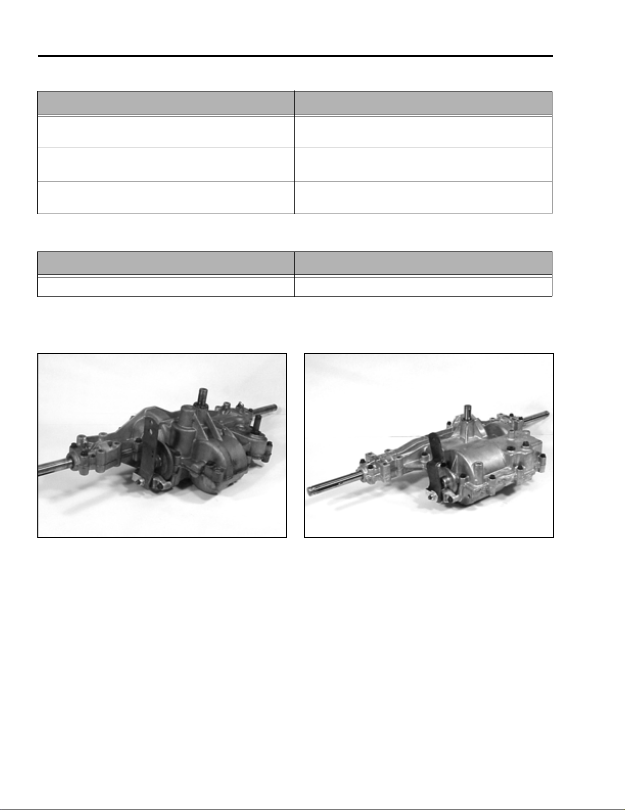
Tecumseh Peerless Transaxles
1993 - 1995
mvc-667
Tecumseh Peerless
Model: 915-020
Lubrication: Bentonite grease (available through
Tecumseh)
NOTE: Tractor may have been converted to current MST-205 transaxle.
Tecumseh Peerless
Model: MST-205
Lubrication: 80W90 gear lube
1996 - Present
mvc-668
For further information on servicing Peerless transaxles, contact Tecumseh Products.
1 - 2 XL Lawn Tractor Service Manual
Page 12
SPECIFICATIONS
Torque Specifications
Recommended fastener torque values are listed in the
following tables. For critical applications, as
determined by Toro, either the recommended torque or
a torque that is unique to the application is clearly
identified and specified in the service manual.
These torque specifications for the installation and
tightening of fasteners shall apply to all fasteners which
do not have a specific requirement identified in the
service manual. The following factors shall be
considered when applying torque: cleanliness of the
fastener, use of a thread sealant (Loctite), degree of
lubrication on the fastener, presence of a prevailing
torque feature, hardness of the surface underneath of
the fastener’s head, or similar condition which affects
the installation.
As noted in the following tables, torque values should
be reduced by 25% for lubricated fasteners to
achieve the similar stress as a dry fastener. Torque
values may also have to be reduced when the fastener
is threaded into aluminum or brass. The specific
torque value should be determined based on the
aluminum or brass material strength, fastener size,
length of thread engagement, etc.
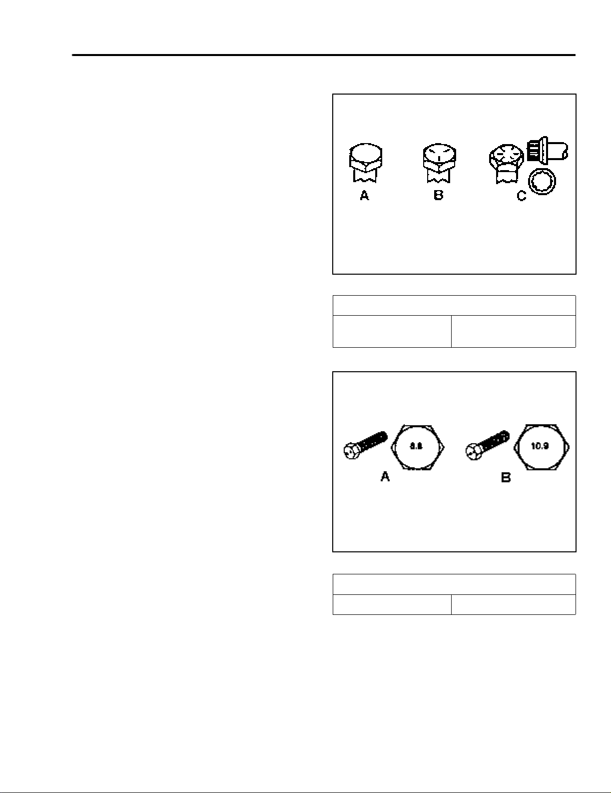
Fastener Identification
Inch Series Bolts and Screws
(A) Grade 1
(B) Grade 5
Figure 1
(C) Grade 8
The standard method of verifying torque shall be
performed by marking a line on the fastener (head or
nut) and mating part, then back off fastener 1/4 of a
turn. Measure the torque required to tighten the
fastener until the lines match up.
Figure 2
Metric Bolts and Screws
(A) Class 8.8 (B) Class 10.9
XL Lawn Tractor Service Manual 1 - 3
Page 13

SPECIFICATIONS
Standard Torque for Dry, Zinc Plated, and Steel Fasteners (Inch Series)
Grade 1, 5, &
Thread Size
# 6 - 32 UNC
# 6 - 40 UNF 17 ± 2 190 ± 20 25 ± 2 280 ± 20
# 8 - 32 UNC
# 8 - 36 UNF 31 ± 3 350 ± 30 43 ± 4 31 ± 3
# 10 - 24 UNC
#10 - 32 UNF 48 ± 4 540 ± 45 68 ± 6 765 ± 70
1/4 - 20 UNC 48 ± 7 53 ± 7 599 ± 79 100 ± 10 1125 ± 100 140 ± 15 1580 ± 170
1/4 - 28 UNF 53 ± 7 65 ± 10 734 ± 113 115 ± 10 1300 ± 100 160 ± 15 1800 ± 170
5/16 - 18 UNC 115 ± 15 105 ± 17 1186 ± 169 200 ± 25 2250 ± 280 300 ± 30 3390 ± 340
5/16 - 24 UNF 138 ± 17 128 ± 17 1446 ± 192 225 ± 25 2540 ± 280 325 ± 30 3670 ± 340
3/8 - 16 UNC 16 ± 2 16 ± 2 22 ± 3 30 ± 3 41 ± 4 43 ± 4 58 ± 5
3/8 - 24 UNF 17 ± 2 18 ± 2 24 ± 3 35 ± 3 47 ± 4 50 ± 4 68 ± 5
7/16 - 14 UNC 27 ± 3 27 ± 3 37 ± 4 50 ± 5 68 ± 7 70 ± 7 68 ± 9
7/16 - 20 UNF 29 ± 3 29 ± 3 39 ± 4 55 ± 5 75 ± 7 77 ± 7 104 ± 9
1/2 - 13 UNC 30 ± 3 48 ± 7 65 ± 9 75 ± 8 102 ± 11 105 ± 10 142 ± 14
1/2 - 20 UNF 32 ± 3 53 ± 7 72 ± 9 85 ± 8 115 ± 11 120 ± 10 163 ± 14
5/8 - 11 UNC 65 ± 10 88 ± 12 119 ± 16 150 ± 15 203 ± 20 210 ± 20 285 ± 27
5/8 - 18 UNF 75 ± 10 95 ± 15 129 ± 20 170 ± 15 230 ± 20 240 ± 20 325 ± 27
3/4 - 10 UNC 93 ± 12 140 ± 20 190 ± 27 265 ± 25 359 ± 34 374 ± 35 508 ± 47
3/4 - 16 UNF 115 ± 15 165 ± 25 224 ± 34 300 ± 25 407 ± 34 420 ± 35 569 ± 47
7/8 - 9 UNC 140 ± 20 225 ± 25 305 ± 34 430 ± 45 583 ± 61 600 ± 60 813 ± 81
7/8 - 14 UNF 155 ± 25 260 ± 30 353 ± 41 475 ± 45 644 ± 61 660 ± 60 895 ± 81
8 with Thin
Height Nuts
In-lb In-lb N-cm In-lb N-cm In-lb N-cm
10 ± 2 13 ± 2 147 ± 23
13 ± 2 25 ± 5 282 ± 30
18 ± 2 30 ± 5 339 ± 56
ft-lb ft-lb N-m ft-lb N-m ft-lb N-m
SAE Grade 1 Bolts, Screws,
Studs, & Sems with Regular
Height Nuts (SAE J995 Grade
2 or Stronger Nuts)
SAE Grade 5 Bolts, Screws,
Studs, & Sems with Regular
Height Nuts (SAE J995 Grade
2 or Stronger Nuts)
15 ± 2 170 ± 20 23 ± 2 260 ± 20
29 ± 3 330 ± 30 41 ± 4 460 ± 45
42 ± 4 475 ± 45 60 ± 6 674 ± 70
SAE Grade 8 Bolts, Screws,
Studs, & Sems with Regular
Height Nuts (SAE J995 Grade
2 or Stronger Nuts)
Note: Reduce torque values listed in the table above
by 25% for lubricated fasteners. Lubricated fasteners
are defined as threads coated with a lubricant such as
oil, graphite, or thread sealant such as Loctite.
Note: The nominal torque values listed above for
Grade 5 and 8 fasteners are based on 75% of the
minimum proof load specified in SAE J429. The
tolerance is approximately
value. Thin height nuts include jam nuts.
± 10% of the nominal torque
Note: Torque values may have to be reduced when
installing fasteners into threaded aluminum or brass.
The specific torque value should be determined based
on the fastener size, the aluminum or base material
strength, length of thread engagement, etc.
1 - 4 XL Lawn Tractor Service Manual
Page 14

SPECIFICATIONS
Standard Torque for Dry, Zinc, and Steel Fasteners (Metric Fasteners)
Class 8.8 Bolts, Screws, and Studs with
Thread Size
M5 X 0.8 57 ± 5 in-lb 640 ± 60 N-cm 78 ± 7 in-lb 885 ± 80 N-cm
M6 X 1.0 96 ± 9 in-lb 1018 ± 100 N-cm 133 ± 13 in-lb 1500 ± 150 N-cm
M8 X 1.25 19 ± 2 ft-lb 26 ± 3 N-m 27 ± 2 ft-lb 36 ± 3 N-m
M10 X 1.5 38 ± 4 ft-lb 52 ± 5 N-m 53 ± 5 ft-lb 72 ± 7 N-m
M12 X 1.75 66 ± 7 ft-lb 90 ± 10 N-m 92 ± 9 ft-lb 125 ± 12 N-m
M16 X 2.0 166 ± 15 ft-lb 225 ± 20 N-m 229 ± 22 ft-lb 310 ± 30 N-m
M20 X 2.5 325 ± 33 ft-lb 440 ± 45 N-m 450 ± 37 ft-lb 610 ± 50 N-m
Note: Reduce torque values listed in the table above
by 25% for lubricated fasteners. Lubricated fasteners
are defined as threads coated with a lubricant such as
oil, graphite, or thread sealant such as Loctite.
Note: Torque values may have to be reduced when
installing fasteners into threaded aluminum or brass.
The specific torque value should be determined based
on the fastener size, the aluminum or base material
strength, length of thread engagement, etc.
Regular Height Nuts
(Class 8 or Strong Nuts)
Note: The nominal torque values listed above are
based on 75% of the minimum proof load specified in
SAE J1199. The tolerance is approximately
the nominal torque value. Thin height nuts include jam nuts.
Class 10.9 Bolts, Screws, and Studs with
Regular Height Nuts (
Class 10 or Strong Nuts)
± 10% of
XL Lawn Tractor Service Manual 1 - 5
Page 15

SPECIFICATIONS
Other Torque Specifications
SAE Grade 8 Steel Set Screws
Recommended Torque
Thread Size
Square Head Hex Socket
1/4 - 20 UNC 140 ± 20 in-lb 73 ± 12 in-lb
5/16 - 18 UNC 215 ± 35 in-lb 145 ± 20 in-lb
3/8 - 16 UNC 35 ± 10 ft-lb 18 ± 3 ft-lb
1/2 - 13 UNC 75 ± 15 ft-lb 50 ± 10 ft-lb
Thread Cutting Screws
(Zinc Plated Steel)
Type 1, Type 23, or Type F
Thread Size Baseline Torque*
No. 6 - 32 UNC 20 ± 5 in-lb
Wheel Bolts and Lug Nuts
Thread Size Recommended Torque**
7/16 - 20 UNF
Grade 5
1/2 - 20 UNF
Grade 5
M12 X 1.25
Class 8.8
M12 X 1.5
Class 8.8
** For steel wheels and non-lubricated fasteners.
Thread
Size
No. 6 18 20 20 ± 5 in-lb
Threads per Inch
Type A Type B
65 ± 10 ft-lb 88 ± 14 N-m
80 ± 10 ft-lb 108 ± 14 N-m
80 ± 10 ft-lb 108 ± 14 N-m
80 ± 10 ft-lb 108 ± 14 N-m
Thread Cutting Screws
(Zinc Plated Steel)
Baseline Torque*
No. 8 - 32 UNC 30 ± 5 in-lb
No.10 - 24 UNC 38 ± 7 in-lb
1/4 - 20 UNC 85 ± 15 in-lb
5/16 - 18 UNC 110 ± 20 in-lb
3/8 - 16 UNC 200 ± 100 in-lb
Conversion Factors
in-lb X 11.2985 - N-cm
ft-lb X 1.3558 = N-m
No. 8 15 18 30 ± 5 in-lb
No. 10 12 16 38 ± 7 in-lb
No. 12 11 14 85 ± 15 in-lb
* Hole size, material strength, material thickness and
finish must be considered when determining specific
torque values. All torque values are based on nonlubricated fasteners.
N-cm X - 0.08851 = in-lb
N-cm X 0.73776 - ft-lb
1 - 6 XL Lawn Tractor Service Manual
Page 16

Equivalents and Conversions
SPECIFICATIONS
XL Lawn Tractor Service Manual 1 - 7
Page 17

THIS PAGE INTENTIONALLY LEFT BLANK
1 - 8 XL Lawn Tractor Service Manual
Page 18
XL GEAR DRIVE
XL Gear Drive Transaxle Removal -
915 Transaxle
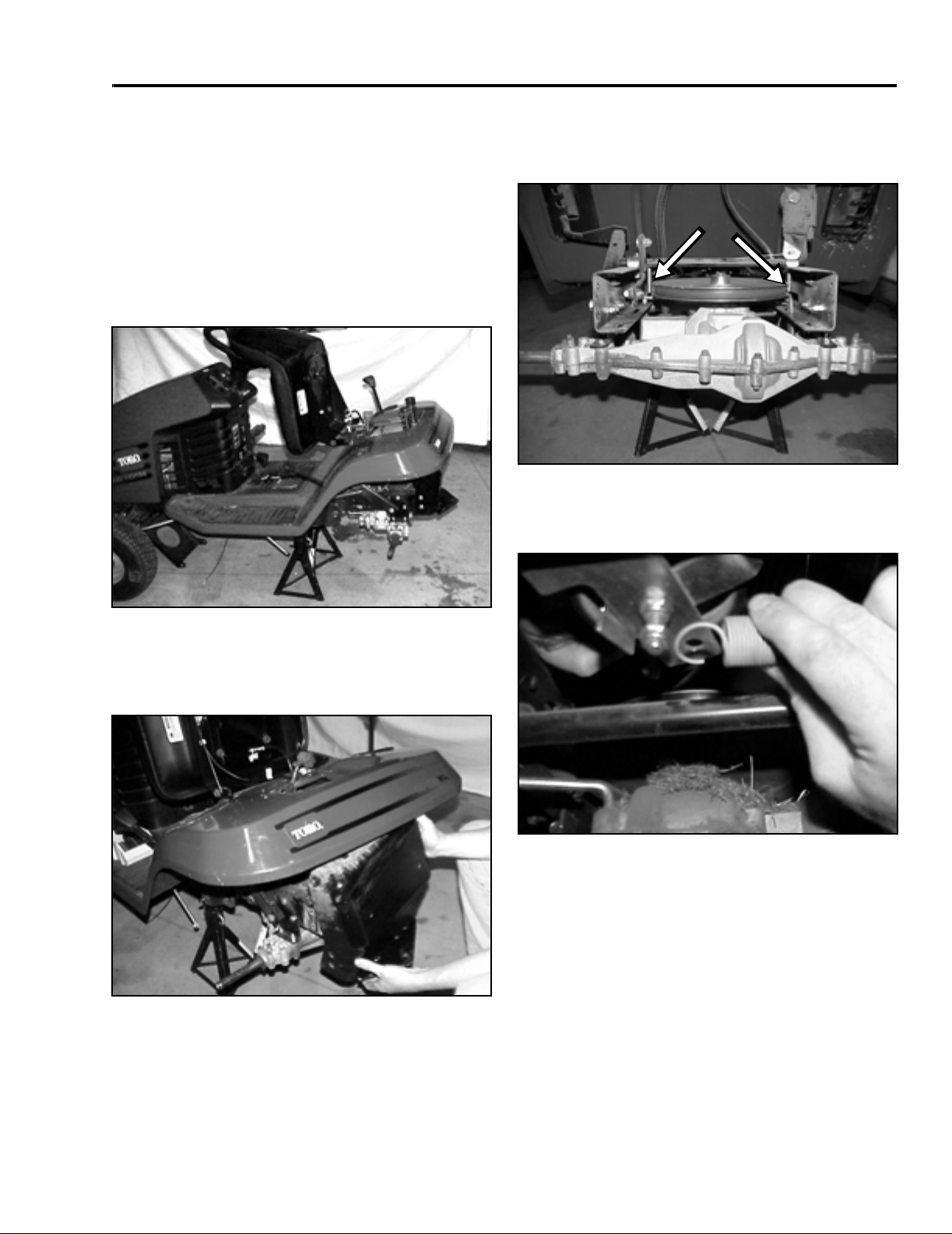
1. Disconnect battery cables and remove the battery
and battery tray. Remove the mower deck (refer
to “Mower” section on page 6 - 1).
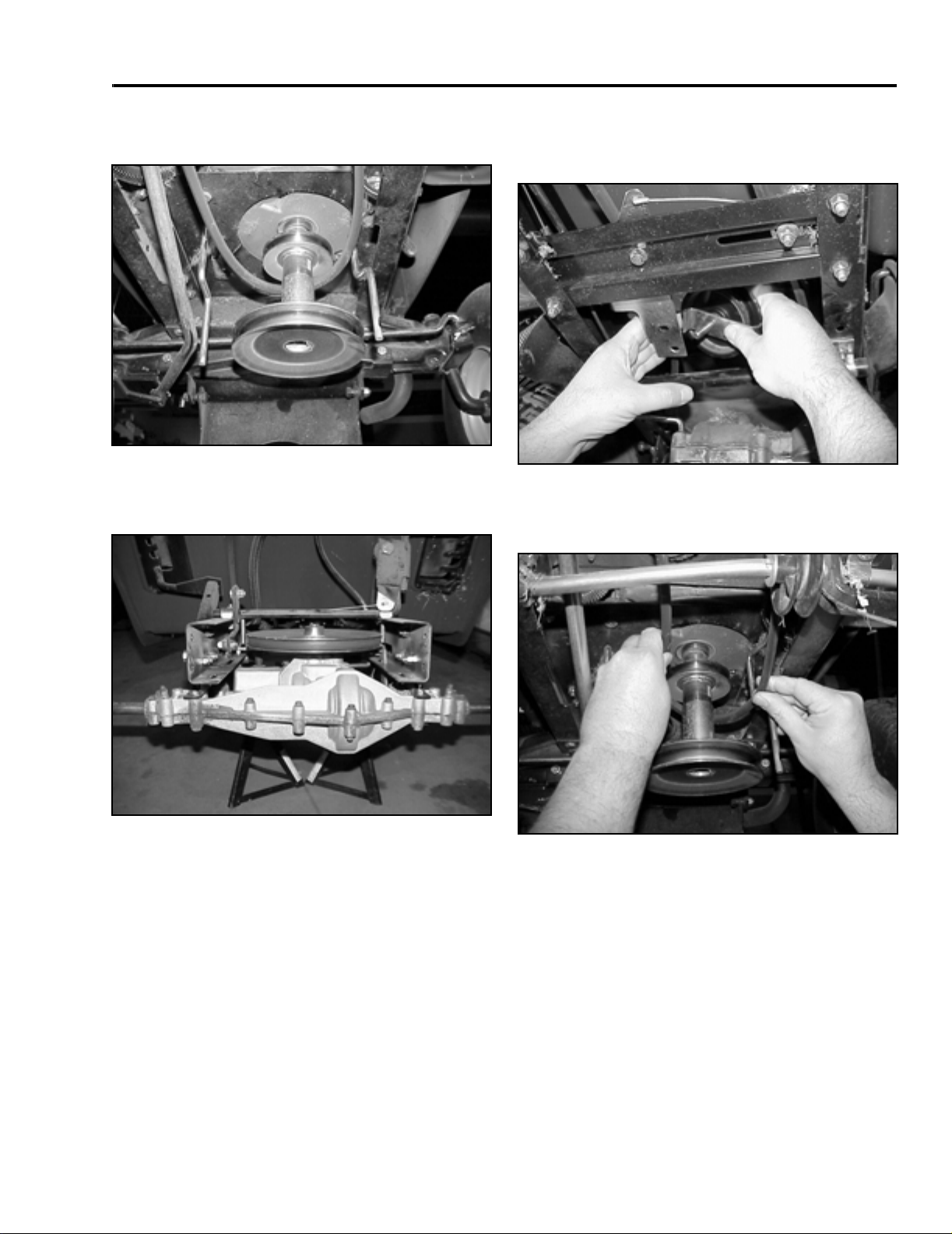
2. Raise the rear of the tractor and remove the right
and left rear tires. Put jack-stands under the
frame, just in front of the transaxle (Figure 3).
4. Loosen the left transaxle belt guide and move it
away from the belt. The right transaxle belt guide
needs to be removed (Figure 5).
Figure 5
5. Unhook the idler spring from the idler assembly
(Figure 6).
mvc-796
Figure 3
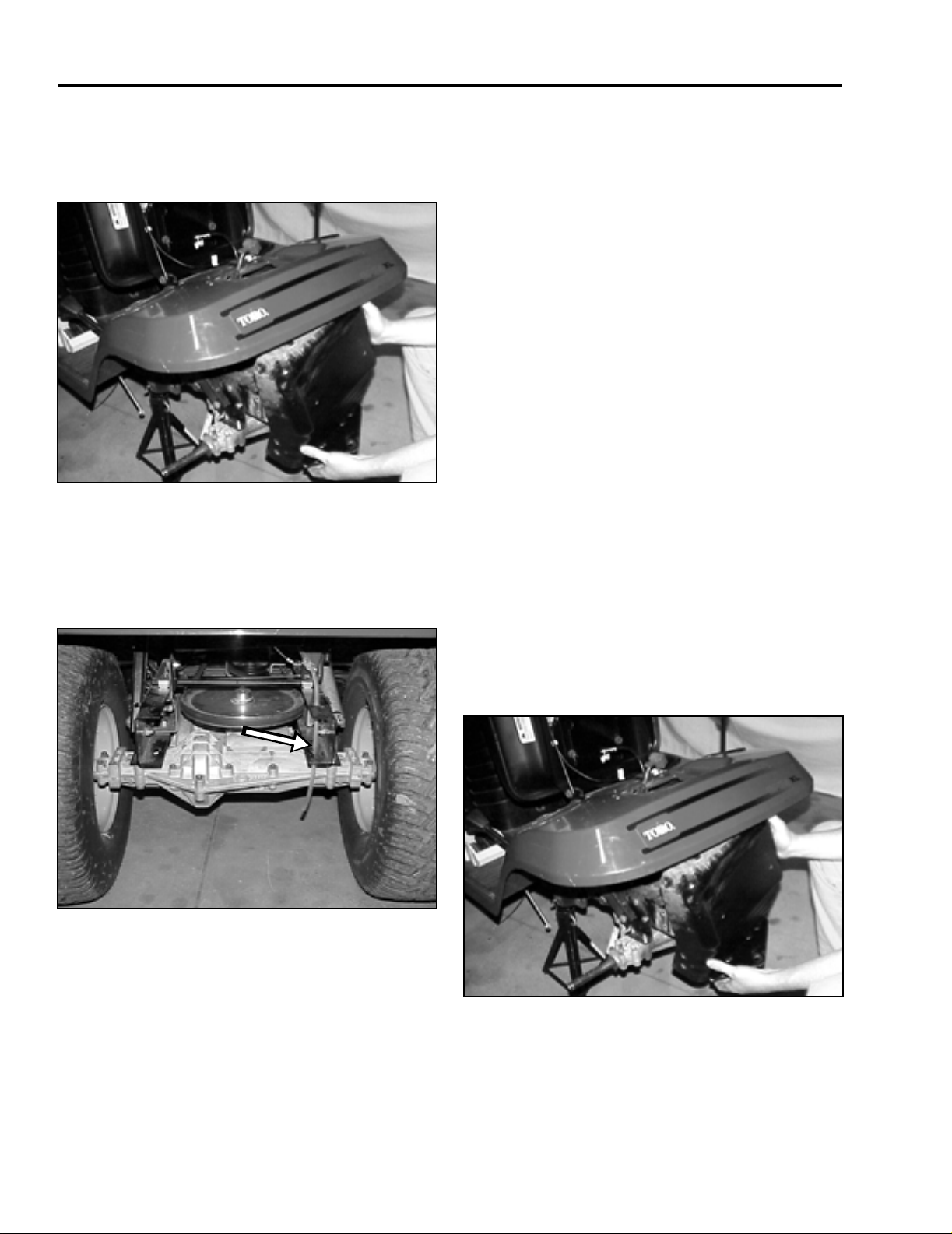
3. Remove the rear hitch panel. There are 2 bolts
and nuts holding the seat springs and 2 bolts and
nuts on each side of the rear panel (Figure 4).
Figure 4
mvc-794
mvc-795
Figure 6
mvc-798
XL Lawn Tractor Service Manual 2 - 1
Page 19

XL GEAR DRIVE
6. Remove the nut on the shift tie rod (Figure 7).
Figure 7
mvc-800
7. Remove the bolt and nut on the left side shift pivot
clamp and slide the shift pivot rod so you can
remove the shift tie rod (Figure 8).
8. Remove the nut and washer holding the left side
torque strap leaving the torque strap bolted to the
frame (Figure 9).
Figure 9
mvc-803
9. Remove both the top and bottom washer and nut
from the right side torque strap (Figure 10).
Figure 8
mvc-802
Figure 10
mvc-806
2 - 2 XL Lawn Tractor Service Manual
Page 20

XL GEAR DRIVE
10. Remove the brake return spring (Figure 11).
Figure 11
11. Unhook the brake spring from the clutch/brake rod
(Figure 12).
mvc-808
A
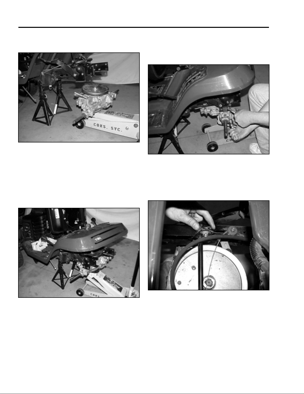
12. Before removing the 4 transaxle bolts, put a floor
jack under the transaxle so you can lower it from
the frame. Remove the 4 bolts, washers, and nuts
(Figure 13).
Figure 13
13. Lower the transaxle slightly so you can free it from
the two front torque straps. Unhook the brake
spring from the transaxle brake arm (Figure 14).
mvc-810
B
Figure 12
(A) Spring (B) Clutch/brake rod
XL Lawn Tractor Service Manual 2 - 3
iso3
Figure 14
mvc-811
Page 21
XL GEAR DRIVE
14. The transaxle should be free from the frame now
(Figure 15).
Figure 15
mvc-813
XL Gear Drive Transaxle Installation
- 915 Transaxle
1. Raise the transaxle to the frame making sure the
brake lever fits through the slot in the frame.
Reinstall the brake spring on the brake lever
(Figure 14 and Figure 16).
2. Install the right and left torque straps to the frame
and the transaxle, do not tighten. Install the 4 axle
bolts, washers, and nuts and tighten first. Then
tighten the torque straps (Figure 17).
Figure 17
3. Install the left side shift pivot clamp on the shift
pivot rod before securing the clamp to the frame.
Make sure the shift tie rod is reinstalled in the hole
in the shift pivot rod. Tighten the shift pivot clamp
and the shift tie rod (Figure 18).
mvc-816
Figure 18
Figure 16
2 - 4 XL Lawn Tractor Service Manual
mvc-814
mvc-817
Page 22

XL GEAR DRIVE
4. Install brake spring to the clutch/brake rod (Figure
19).
A
B
Figure 19
(A) Spring (B) Clutch/brake rod
5. Install belt around the transaxle pulley. Reinstall
the idler spring to the idler assembly (Figure 20).
iso3
6. Install the right and left belt guides and adjust so
they are within 1/8” (3mm) of the transaxle pulley
and drive belt (Figure 21). Note direction of belt
guide installation, right hand points forward, left
hand points rearward.
1/8” (3mm)
1/8” (3mm)
Figure 21
7. Connect the brake return spring to the brake lever
(Figure 22).
mvc-818
Figure 20
XL Lawn Tractor Service Manual 2 - 5
mvc-798
Figure 22
mvc-819
Page 23
XL GEAR DRIVE
8. Install the rear hitch panel. There are two bolts,
washers, and nuts on each side of the plate and 2
bolts, washers, and nuts for the seat springs
(Figure 23).
Figure 23
9. Install the right and left rear tires. Install the
battery and battery box. Note: Make sure the
battery drain tube is installed through the rear hole
of the frame (Figure 24; rear hitch panel removed
for clarity).
mvc-795
10. Check the following items:
A. The Shift-On-The-Go for proper adjustment. If
adjustment is needed, (refer to “Cable
Adjustment, Shift-On-The-Go, 915 and MST205 Transaxle” on page 2 - 19).
B. Brake Adjustment. If adjustment is needed,
(refer to “XL Gear Drive Brake Adjustment -915
Transaxle” on page 2 - 11).
C. Shift Lever Adjustment. If adjustment is
needed, (Refer to “XL Gear Drive Shift Lever
Adjustment - 915 Transaxle” on page 2 - 9).
11. Install mower deck; see instructions in the Mower
section.
12. Check all safety switches to make sure they are
operating properly.
XL Gear Drive Traction Drive Belt
Replacement Procedure - 915
Transaxle
1. Disconnect battery and remove battery and
battery tray. Remove mower deck. (Refer to
Mower section.)
Figure 24
mvc-639
2. Remove the rear hitch panel. There are 2 bolts
and nuts holding the seat springs and 2 bolts and
nuts on each side of the rear panel (Figure 25).
Figure 25
mvc-795
2 - 6 XL Lawn Tractor Service Manual
Page 24
XL GEAR DRIVE
3. Loosen and move the right and left engine belt
guides (Figure 26).
Figure 26
mvc-821
4. Loosen the left side transaxle belt guide. Remove
the right side transaxle belt guide (Figure 27).
5. Remove the idler spring on the idler assembly.
Remove the idler pulley and belt guide (Figure
28). Remove the drive belt.
Figure 28
mvc-824
6. Install new belt around the engine drive pulley
(Figure 29).
Figure 27
mvc-796
Figure 29
mvc-825
XL Lawn Tractor Service Manual 2 - 7
Page 25

XL GEAR DRIVE
7. Route belt back over the pedal pivot rod, the idler
pivot bracket, and around the transaxle pulley
(Figure 30).
Figure 30
8. Install the idler pulley to the idler bracket. Note
the correct hole location of the bolt and nut
retaining the pulley and belt guide bracket (Figure
31).
mvc-826
9. Hook the idler spring to the idler bracket (Figure
32).
Figure 32
10. Install the right side belt guide and adjust to within
1/8” (3mm) of the transaxle pulley and belt. Adjust
and tighten the left belt guide so it is within 1/8”
(3mm) of the transaxle pulley and belt (Figure 21
and Figure 33).
mvc-829
1/8” (3mm)
Figure 31
2 - 8 XL Lawn Tractor Service Manual
mvc-828
Figure 33
mvc-796
Page 26

XL GEAR DRIVE
11. Recheck the routing of the belt (Figure 34).
Figure 34
12. Install the mower deck. (Refer to Mower Deck
section). Make sure the engine belt guides are
adjusted so they are within 1/8” (3mm) of both the
engine and mower drive pulley.
13. Install battery and battery tray making sure the
battery drain tube is installed in the rear hole of
the frame (Figure 35). Install the rear hitch panel
(Figure 25).
mvc-833
14. Check the following:
A. The Shift-On-The-Go for proper adjustment. If
adjustment is needed, (refer to “Cable
Adjustment, Shift-On-The-Go, 915 and MST205 Transaxle” on page 2 - 19).
B. Brake Adjustment. If adjustment is needed,
(refer to “XL Gear Drive Brake Adjustment -915
Transaxle” on page 2 - 11).
C. Shift Lever Adjustment. If adjustment is
needed, (refer to “XL Gear Drive Shift Lever
Adjustment - 915 Transaxle” on page 2 - 9).
15. Check all safety switches to make sure they are
operating properly.
XL Gear Drive Shift Lever
Adjustment - 915 Transaxle
It is VERY important the shift lever is properly aligned
with the shift gates.
If the gear shift lever and shift gates do not properly
align, you may encounter the following symptoms:
1. No reverse.
2. No fifth gear.
3. Jumping out of gear.
Figure 35
If the misalignment is ignored for a period of time,
severe transaxle damage will result.
Adjust using the following procedure:
1. Disconnect the battery cables and remove the
battery and battery tray.
mvc-639
XL Lawn Tractor Service Manual 2 - 9
Page 27

XL GEAR DRIVE
2. Remove the rear hitch panel by removing the two
bolts and nuts holding the seat springs and two
bolts and nuts located on each side of the hitch
panel. Loosen the fastener securing the front
cable guide to remove tension from the shift cable
(Figure 36).
Figure 36
mvc-834
3. Remove the rubber shift gate cover (Figure 37).
4. Shift the transaxle through each gear to verify the
gear shift lever centers in each gate as the internal
transaxle detents are felt. The lever should also
“detent” into 5th gear and reverse (Figure 38).
That is, the shift lever should not contact the side
of the metal “fingers” of each gate as the lever
enters the gate.
Figure 38
mvc-836
5. If the shifter does not align with the gates, loosen
the bolt and nut between the shift pivot and the
shift pivot lever and adjust (Figure 39).
Figure 37
mvc-835
Figure 39
mvc-840
2 - 10 XL Lawn Tractor Service Manual
Page 28

XL GEAR DRIVE
6. If the shifter still does not go into 5th gear, loosen
the jam nut on the tie rod end of the shift arm and
remove the nut. Rotate the tie rod end until the
gear shift lever is centered in the 5th gear gate.
Place the shift arm on the gear selector shaft and
verify that neutral, reverse, and fifth gears properly
align. Reinstall the shift arm fastener and tighten
the jam nut (Figure 40).
Figure 40
(1) Jam Nut
(2) Fastener
7. Reassembly:
A. Ensure the transaxle and engine pulley belt
guides are positioned 1/8” (3mm) away from
the drive belt.
B. Adjust the transaxle shift cable (refer to “Cable
Adjustment, Shift-On-The-Go, 915 and MST205 Transaxle” on page 2 - 19.)
C. Reinstall the shift gate cover, rear hitch panel,
battery, and battery tray. Note: Make sure the
battery drain tube is installed in rear hole of the
frame (Figure 35). Reconnect the battery
cables.
D. Test drive the tractor and verify all adjustments
and safety switches are operating properly.
(3) Shift Arm
HL11014
XL Gear Drive Brake Adjustment 915 Transaxle
The brake is located on the right side of the rear axle,
inside the rear tire. If the brake does not hold securely
or stopping power is insufficient, an adjustment is
required (Figure 41).
Figure 41
1. Park the machine on a level surface, disengage
the blade control (PTO), shift into neutral, set the
parking brake, and turn the ignition key to “OFF” to
stop the engine.
2. If the rear wheels lock and skid when you push the
tractor forward, no adjustment is required. An
adjustment is required if the wheels turn and do
not lock.
3. To increase braking resistance, tighten the brake
adjusting nut (Figure 41) 1/8 turn clockwise; then
check the brake again. Continue this adjusting
and checking process until the brake is set
properly.
If the brake system does not respond to
adjustment, the brake pads and possibly the brake
disc, require replacement.
mvc-847
4. Push down on the clutch/brake pedal to release
the parking brake.
IMPORTANT: With the parking brake released,
the rear wheels must rotate freely when you push
the tractor. If the brake seems to “drag”, loosen
the adjusting nut slightly until the wheels rotate
freely.
XL Lawn Tractor Service Manual 2 - 11
Page 29

XL GEAR DRIVE
XL Gear Drive MST-205 Transaxle
Removal
1. Disconnect battery cables and remove battery and
battery tray. Remove mower deck (refer to
“Mower” section on page 6 - 1). Lift the rear of the
tractor and remove both the right and left rear tires
(Figure 42).
Figure 42
2. Remove the rear hitch panel, removing the two
bolts and nuts holding the seat springs and two
bolts and nuts located on each side of the hitch
panel (Figure 43).
mvc-0001
3. Remove the right and left transaxle belt guides.
Put the park brake on and then slip the traction
drive belt off the transaxle pulley (Figure 44).
A
Figure 44
(A) Belt Guides
4. Release the park brake and disconnect the brake
spring (A) at the idler arm assembly. Remove the
brake return spring (B) (Figure 45).
mvc-0002
A
B
Figure 45
(A) Brake Spring (B) Brake Return Spring
Figure 43
2 - 12 XL Lawn Tractor Service Manual
mvc-0037
mvc-0005
Page 30

XL GEAR DRIVE
5. Disconnect the shift link at the transaxle shift lever
(Figure 46).
Figure 46
6. Use a floor jack to support and lower the transaxle
from the frame. Unbolt and remove the two torque
strap bolts located in the front of the transaxle.
Remove the 4 axle bolts holding the transaxle to
the frame (Figure 47).
mvc-0003
XL Gear Drive MST-205 Transaxle
Installation
1. Raise the transaxle up to the frame and install the
4 axle bolts and 2 torque strap bolts. Tighten all 6
bolts (Figure 48).
A
Figure 48
(A) Torque Straps
mvc-0011
Figure 47
mvc-0004
2. Connect the brake spring between the clutch/
brake rod and the transaxle brake lever. Install
the brake return spring, located between the
transaxle brake lever and the axle frame bracket.
A
B
Figure 49
(A) Brake Spring (B) Brake Return Spring
mvc-0005
XL Lawn Tractor Service Manual 2 - 13
Page 31

XL GEAR DRIVE
3. Place the traction drive belt around the transaxle
input pulley. Install the right and left belt guides.
A
Figure 50
(A) Belt Guides
4. Install battery and battery tray. Note: If the
battery uses a battery drain tube, make sure
the tube is reinstalled through the rear hole in
the frame (Figure 51). Connect the battery
cables. Start the tractor and check the shift
linkage and the brakes to make sure they are
operating properly. If adjustment is needed, refer
to “Adjusting the Brake” on page 2 - 15 or “XL
Gear Drive Shift Lever Adjustments, MST-205
Transaxle” on page 2 - 14. Test and operate the
safety interlock system.
mvc-0002
5. Install the rear hitch panel (Figure 52).
Figure 52
6. Re-install the mower deck (“Mower” section on
page 6 - 1).
mvc-0037
XL Gear Drive Shift Lever
Adjustments, MST-205 Transaxle
It is VERY important the shift lever is properly aligned
with the shift gates. If misalignment is ignored for a
period of time, severe transaxle damage will result.
After any transmission or shift linkage repair, or if you
experience difficulty shifting the linkage from 1st
through 5th or in reverse gear, adjust using the
following procedure:
th
1. Place the gear shift lever in 5
Figure 51
2 - 14 XL Lawn Tractor Service Manual
mvc-639
Figure 53
gear (Figure 53).
mvc-640
Page 32

XL GEAR DRIVE
2. Loosen the bolt between the shift pivot and the
shift pivot lever (Figure 54).
Figure 54
3. Make sure the shift lever is in the center of the
shift gate (Figure 55).
mvc-644
XL Gear Drive Brake Adjustment,
MST-205 Transaxle
The brake is located on the right side of the rear axle,
inside the rear tire. If the brake does not hold securely
or stopping power is insufficient, an adjustment is
required (Figure 56).
Figure 56
mvc-648
Figure 55
4. Tighten bolt and retest the shifting; make sure the
gear shift lever is centered in each gate for each
gear.
mvc-645
Checking the Brake
1. Park the machine on level surface, disengage the
PTO, shift into neutral, set the parking brake, stop
the engine, remove the ignition key.
2. If the rear wheels lock and skid when you push the
tractor forward, no adjustment is required. An
adjustment is required if the wheels turn and do
not lock; refer to Adjusting the Brake (below).
Adjusting the Brake
1. Check the brake before you make any
adjustments; refer to Checking the Brake (above).
2. To increase braking resistance, tighten the brake
adjusting nut 1/8 turn clockwise; then check the
brake again. Continue this adjusting and checking
process until the brake is set properly.
If the brake system does not respond to
adjustment, the brake pads and possibly the brake
disc, require replacement.
3. Push down on the clutch/brake pedal to release
the parking brake.
XL Lawn Tractor Service Manual 2 - 15
Page 33

XL GEAR DRIVE
Important
wheels must rotate freely when you push the tractor. If
the brake seems to drag, loosen the adjusting nut
slightly until the wheels rotate freely.
: With the parking brake released, the rear
XL Gear Drive Traction Drive Belt
Replacement Procedure, MST-205
Transaxle
1. Remove mower deck from tractor (refer to
“Mower” section on page 6 - 1).
2. Disconnect the battery cables and remove the
battery and battery tray.
3. Disconnect the rear hitch plate. Remove the two
seat spring bolts and 2 bolts and nuts located on
each side of the rear hitch plate (Figure 57).
4. Remove the right and left belt guides located on
each side of the transaxle pulley (Figure 58).
A
Figure 58
(A) Belt Guides
5. Unhook idler spring and unbolt the idler pulley
from the idler bracket (Figure 59).
mvc-0002
Figure 57
2 - 16 XL Lawn Tractor Service Manual
mvc-0037
Figure 59
mvc-0010
Page 34

XL GEAR DRIVE
6. Loosen the right and left belt guides located on
each side of the engine drive pulley (Figure 60).
Remove the drive belt.
Figure 60
mvc-000D
7. Install new belt around the engine drive pulley and
route it back to the transaxle pulley (Figure 61).
8. Install belt on the idler pulley and tighten the pulley
bolt (Figure 62).
Figure 62
mvc-0010
9. Install the right and left transaxle belt guides
(Figure 63).
mvc-000F
Figure 61
Figure 63
mvc-000B
XL Lawn Tractor Service Manual 2 - 17
Page 35

XL GEAR DRIVE
10. Reinstall the idler spring on bolt holding the idler
pulley to the idler assembly (Figure 64).
Figure 64
11. Adjust both the right and left engine belt guides so
they are within 1/8” (3mm) of the engine pulley
(Figure 65).
mvc-000a
12. Install rear hitch plate and seat springs (Figure
66).
Figure 66
13. Install battery and battery tray. Note: If battery
uses a battery drain tube, make sure the tube
is reinstalled through the rear hole in the
frame (Figure 67). Connect the battery cables.
mvc-0037
1/8” (3mm)
Figure 65
mvc-000E
Figure 67
14. Reinstall the mower deck (refer to “Mower” section
on page 6 - 1).
15. Test operate the tractor to make sure the unit
shifts, brakes, and shifts on-the-go properly. Test
the safety interlock system.
mvc-639
2 - 18 XL Lawn Tractor Service Manual
Page 36

XL GEAR DRIVE
Cable Adjustment, Shift-On-The-Go,
915 and MST-205 Transaxle
1. Adjustment is required if the gearshift lever is not
pulled firmly under spring tension toward the
numbers on the shift plate or if it is difficult to shift
on-the-go (Figure 68). If either of these problems
present themselves, check the following:
Figure 68
• Verify that the idler pulley is not damaged.
• Verify that the belt guides are within 1/8” (3mm)
of the engine and transaxle pulleys.
• Check proper cable tension. When properly
adjusted, the cable is under light tension.
Approximately 1/2” (13mm) deflection should
be noticed when light side pressure is applied
(Figure 69). To adjust:
mvc-0009
A. Loosen the fastener securing the forward cable
guide. It is located just above and behind the
mower deck pulley (Figure 70).
Figure 70
B. Slide the guide left or right as necessary to
remove all slack, but do not tighten so much as
to move the idler arm. Retighten the fastener
once adjustment is complete.
C. Verify that the adjustment is correct by
checking that the gearshift lever snaps crisply
toward the numbers on the shift plate. Also
make sure that the unit shifts easily on-the-go
(In other words, the drive belt is fully
declutched when shifting) (Figure 71).
mvc-000A
Figure 71
Figure 69
XL Lawn Tractor Service Manual 2 - 19
mvc-0007
mvc-0009
Page 37

THIS PAGE INTENTIONALLY LEFT BLANK
2 - 20 XL Lawn Tractor Service Manual
Page 38

XL HYDROSTATIC TRANSAXLES
Identification
Hydro-Gear 0500/0750 Transaxle
Used: 1993 - 2000
Models: 316-0500, 321-0500, 323-0500,
316-0750, and 326-0750
mvc-658
Hydro-Gear 0510 Transaxle
Used: 2001 and later
Model: 318-0510
mvc-660
Lubrication: 20W50 Motor Oil
Oil Level: Oil level should not be more than 1¼”
(3.17cm) below the top fill port.
Lubrication: 20W50 Motor Oil
Oil Level: Oil level should be at 1.75” to 2.0” (4.39cm
- 5.08cm) from the top of the housing.
mvc-659
mvc-661
XL Lawn Tractor Service Manual 3 - 1
Page 39

XL HYDROSTATIC TRANSAXLES
Internal Service
Refer to the Tractor Parts Catalog for available
The Hydro-Gear 310-0500/0700 Service Manual is
available from Toro under Form #492-4712.
The Hydro-Gear 310-0510 Service Manual is available
from Toro under Form #492-4735.
Troubleshooting Chart
Symptom Possible Cause Corrective Action
Operates in one direction only Inspect control linkage **Repair or replace
Inspect drive belt and pulleys Repair or replace
Check oil level and condition Fill to proper level or change oil
Check for excessive loading Reduce vehicle loading
Noisy
Low Power
Operating Hot
Check brake setting *Adjust brake or proper setting
Check for loose parts Repair or replace loose parts
Check bypass valve linkage operation Repair or replace linkage
Check frame mount Tighten to frame
Check engine RPM Adjust to correct setting
Check drive belt and pulleys Repair or replace
Check oil level and condition Fill to proper level or change oil
Check for excessive loading Reduce vehicle load
Check brake setting *Adjust brake to proper setting
Check for loose parts Repair or replace loose parts
Check bypass valve linkage operation Repair or replace linkage
Check for loose or improper linkage Tighten linkage or replace
Check for debris build up Clean off debris
Check oil level and condition Fill to proper level or change oil
Check for excessive loading Reduce vehicle loading
Check brake setting *Adjust brake to proper setting
Check fan condition Replace if needed
transaxle service parts.
For 1993 - 1995 model year tractors, refer to the
comparable 1996 model, as spare parts were not
shown in earlier parts catalogs.
*Make sure brake isn’t stuck in “on” position. Remove brake parts as necessary to test.
**If installing new transaxle, be sure bolt securing linkage in neutral position is removed and discarded.
3 - 2 XL Lawn Tractor Service Manual
Page 40

XL HYDROSTATIC TRANSAXLES
Purging Procedures
Due the effects air has on efficiency in hydrostatic drive
applications, it is critical that it be purged from the
system.
These purge procedures should be implemented any
time a hydrostatic system has been opened to facilitate
maintenance or any additional oil has been added to
the system.
Air creates inefficiency because its compression and
expansion rate is higher than that of the oil normally
approved for use in hydrostatic drive systems.
The resulting symptoms in hydrostatic systems may
be:
1. Noisy operation.
2. Lack of power or drive after short term operation.
3. High operation temperature and excessive
expansion of oil.
Before starting, make sure the transaxle is at the
specified oil level, page 3 - 1.
The following procedures should be performed with the
vehicle drive wheels off the ground, then repeated
under normal operating conditions.
1. With the bypass valve open and the engine
running, slowly move the directional control (foot
control) in both forward and reverse directions 5 to
6 times; as air is purged from the unit, the oil level
will drop.
Fluid Change
The Hydro-Gear transaxle is factory filled, sealed and
does not require oil maintenance. However, in the
event of oil contamination or degradation, oil
replacement may correct certain performance
problems.
Remove the transaxle from the vehicle and drain the oil
from the top fluid fill port. Fill unit as near the top of fill
port as is practical. Tipping the unit forward, backward
and from side to side will allow air to escape. The
tipping and filling activity may need to be repeated
several times. Refer to the oil fill range for the HydroGear model transaxle. Reinstall transaxle and perform
purging procedures.
If the oil drained from the transaxle is severely
contaminated or overheated, the transaxle should be
disassembled for inspection, cleaning, and repair, as
needed.
HXL Hydro Transaxle Removal 2000 and Prior
1. Disconnect battery cables and remove the battery
and battery tray. Remove the mower deck (refer
to "Mower" section on page 6 - 1).
2. Raise the rear of the tractor and remove the right
and left rear tires. Put jack stands under the
frame, just in front of the transaxle (Figure 72).
2. With the bypass valve in the closed position and
the engine running, slowly move the directional
control valve (foot control) in both forward and
reverse directions 5 to 6 times. After stopping the
engine, check the oil level and add oil as required.
3. It may be necessary to repeat Steps 1 and 2 until
all the air is completely purged from the system.
When the transaxle moves forward and reverse at
normal speed purging is complete.
Figure 72
XL Lawn Tractor Service Manual 3 - 3
MVC-0038
Page 41

XL HYDROSTATIC TRANSAXLES
3. Remove the rear hitch panel. There are 2 bolts
and nuts holding the seat springs and 2 bolts and
nuts on each side of the rear panel (Figure 73).
Figure 73
MVC-0037
4. Loosen the left and right rear transaxle belt guides
and move them away from the belt (Figure 74).
5. Loosen the right and left belt guides located on
each side of the engine drive pulley (Figure 75).
Figure 75
MVC-0045
6. Unhook the idler spring from the idler assembly
(Figure 76).
MVC-001C
Figure 74
Figure 76
MVC-0039
3 - 4 XL Lawn Tractor Service Manual
Page 42

XL HYDROSTATIC TRANSAXLES
7. Slip the traction belt down off the engine pulley
and move the slack of the belt back toward the
rear of the tractor. You should now be able to slip
the traction belt up off the transaxle drive pulley.
The fan is flexible enough to allow you to remove
the belt (Figure 77).
Figure 77
MVC-003A
8. Remove the hairpin and washer on the speed
control rod (Figure 78).
9. Remove the hairpin and washer on the bypass
lever rod (Figure 79).
Figure 79
MVC-0041
10. Remove the small brake return spring from the
brake lever (Figure 80).
MVC-003D
Figure 78
Figure 80
MVC-003B
XL Lawn Tractor Service Manual 3 - 5
Page 43

XL HYDROSTATIC TRANSAXLES
11. Unhook the brake spring from the clutch/brake
rod.
A
B
Figure 81
(A) Brake Spring (B) Unhook from clutch/
brake rod
12. Unbolt the torque strap (Figure 82).
iso3
13. Support the transaxle with a jack. Remove the 4
bolts, washers, and nuts holding the transaxle to
the frame (Figure 83).
Figure 83
14. Lower the transaxle from the frame (Figure 84).
MVC-0042
Figure 84
Figure 82
3 - 6 XL Lawn Tractor Service Manual
MVC-003E
MVC-0040
Page 44

XL HYDROSTATIC TRANSAXLES
HXL Hydro Lawn Tractor Transaxle
Installation – 2000 and Prior
1. Raise the transaxle to the frame and install the 4
axle bolts, washers, and nuts (Figure 85).
Figure 85
2. Install the washer and nut to the torque strap and
tighten (Figure 86).
MVC-0042
3. Reconnect the brake spring to the clutch/brake
rod (Figure 87).
A
B
Figure 87
(A) Spring (B) Clutch/brake rod
4. Hook the small brake return spring to the brake
arm (Figure 88).
iso3
Figure 86
XL Lawn Tractor Service Manual 3 - 7
MVC-0043
Figure 88
MVC-003D
Page 45

XL HYDROSTATIC TRANSAXLES
5. Install the washer and hairpin on the speed control
rod (Figure 89).
Figure 89
MVC-003B
6. Install the washer and hairpin that holds the
bypass lever (Figure 90).
7. Install the traction drive belt around the transaxle
input pulley (Figure 91).
Figure 91
MVC-003A
8. Install the traction drive belt around the engine
drive pulley (Figure 92).
Figure 90
MVC-0041
Figure 92
MVC-0045
3 - 8 XL Lawn Tractor Service Manual
Page 46

XL HYDROSTATIC TRANSAXLES
9. Reconnect the idler spring to the idler bracket
assembly (Figure 93).
Figure 93
10. Adjust and tighten the right and left engine belt
guides so the guides are within 1/8” (3mm) of the
belt and pulley (Figure 94).
MVC-001C
11. Adjust and tighten the right and left rear transaxle
belt guides. Adjust the guides so they are within
1/8” (3mm) of the belt and pulley (Figure 95).
1/8” (3mm)
Figure 95
12. Install the rear hitch plate. There are 2 bolts,
washers, and nuts on each side of the plate and 2
bolts, washers, and nuts for the seat springs
(Figure 96).
MVC-0039
1/8” (3mm)
Figure 94
XL Lawn Tractor Service Manual 3 - 9
MVC-001F
Figure 96
MVC-0037
Page 47

XL HYDROSTATIC TRANSAXLES
13. Install the battery and battery tray. Note: If the
battery uses a drain tube, make sure the tube
is reinstalled through the rear hole in the
frame (Figure 97).
Figure 97
14. Install the left rear tire only and lower the tractor
so the left rear tire touches the ground (Figure 98).
mvc-647
17. Install the right rear tire and check the brake
adjustments. If adjustment is needed, follow the
procedures in the “Brake Adjustment - HXL Hydro
- 2000 and Prior” on page 3 - 11.
18. Test operate the tractor, making sure the unit
operates properly and the safety circuits are
operating.
Neutral Adjustment - HXL Hydro2000 and Prior
Before making a neutral adjustment, the transaxle
must be warmed up for at least 10 minutes. Steps to
perform neutral adjustment:
1. Jack-up and support the right rear end of the
tractor, allowing enough clearance to remove the
right rear tire. Make sure the left rear tire stays on
the ground (Figure 99).
Figure 99
Figure 98
15. If a new transaxle was installed or any work was
performed internally on the transaxle, follow the
“Purging Procedures” on page 3 - 3.
16. Check the neutral adjustment. If the unit needs to
be neutralized, follow the procedures in the
“Neutral Adjustment - HXL Hydro- 2000 and Prior”
on page 3 - 10.
3 - 10 XL Lawn Tractor Service Manual
mvc-0044
mvc-649
Page 48

XL HYDROSTATIC TRANSAXLES
2. Loosen the locknut (Figure 100).
Figure 100
3. Move the peg up or down until the wheel creep is
minimized. There may still be a slight creep with
the wheel off the ground (Figure 101).
mvc-651
4. Tighten the locknut. Move the motion control
pedal forward and reverse and allow it to recenter.
Verify that there is still no creep with the wheels
on the ground.
When operating the foot control, if you find too much
ground speed in forward and not enough in reverse or
too much ground speed in reverse and not enough in
froward, the pivot block which the speed control pedal
is mounted on is adjustable. To adjust, loosen the two
bolts, which are in two slots in the foot rest, and move
the pivot block either forward or back to alter the
maximum ground speed in either forward or reverse
(Figure 102).
Figure 101
mvc-651
Figure 102
mvc-653
Brake Adjustment - HXL Hydro 2000 and Prior
1. Park the machine on a level surface, disengage
the blade control (PTO). Set the parking brake,
and turn the ignition key to “OFF” to stop the
engine.
2. Move the bypass lever to the push mode position.
3. If the rear wheels lock and skid when you push the
tractor forward, no adjustment is required, An
adjustment is required if the wheels turn and do
not lock.
4. Release the parking brake.
XL Lawn Tractor Service Manual 3 - 11
Page 49

XL HYDROSTATIC TRANSAXLES
5. To adjust the brake, loosen the brake adjusting
nut slightly (Figure 103).
1. Check to see if the brake lever returns to the
“OFF” position when the pedal is released (Figure
105).
Figure 103
mvc-654
6. Insert a 0.020” (.5mm) feeler gauge between the
outer discs, if the clearance is not correct make
the necessary change with the brake adjusting nut
(Figure 104).
Figure 104
L11051
(A) Adjusting Nut (B) Outer Brake Discs
Figure 105
4017-09
2. If the brake lever is not returning to the “OFF”
position, it may be necessary to install a shorter
spring. The spring on the left is a shorter spring
P/N 26-6700. The shorter spring is installed on all
the 2000 model year Lawn Tractors. The spring
on the right is the longer spring P/N 26-6701
(Figure 106).
7. Tighten the brake adjusting nut until slight
resistance is felt on the feeler gauge when sliding
it in and out.
Figure 106
4017-10
3. Next, check the actuating pins for any corrosion,
8. Check the brake operation again.
dirt, or residue build-up. Remove the brake lever
and pins and clean with a cleaning solvent. WD-
Important:
With the parking brake released and the
40 can be applied to the pins as a lubricant.
bypass lever in the push mode, the rear wheels must
rotate freely when you push the unit. If they do not
rotate freely, perform the following procedure:
3 - 12 XL Lawn Tractor Service Manual
Page 50

XL HYDROSTATIC TRANSAXLES
If the battery drain tube is installed improperly
through the frame, the battery will drain in this
area and corrode the pins and linkage (Figure
107).
Figure 107
4. Check the brake rotors for dirt or debris. Clean
and flush out the brake rotors using either WD-40
or a brake cleaner. After cleaning, check the
brake adjustments (Figure 108).
4017-18
Traction Drive Belt Replacement On
HXL Hydro - 2000 and Prior
1. Remove the mower deck from the tractor, refer to
"Mower" section on page 6 - 1.
2. Disconnect the battery cables and remove the
battery and battery tray.
3. Loosen the right and left rear transaxle belt guides
and swing them away from the transaxle input
pulley (Figure 109).
Figure 108
NOTE: Transaxle shown bottom side up.
4017-19
Figure 109
4. Loosen the right and left belt guides located on
each side of the engine pulley. Swing the belts
guides away from the pulley (Figure 110).
Figure 110
mvc-0039
mvc-0045
XL Lawn Tractor Service Manual 3 - 13
Page 51

XL HYDROSTATIC TRANSAXLES
5. Unhook the idler spring on the idler spring bracket
(Figure 111).
Figure 111
mvc-001C
6. Unbolt the idler pulley assembly with belt guide
and remove assembly (Figure 112).
7. Install belt around the engine drive pulley and feed
the drive belt up over the pedal pivot rod (Figure
113).
Figure 113
mvc-0021
8. Continue feeding the belt back up over the idler
pivot bracket and around the transaxle drive pulley
(Figure 114).
Figure 112
mvc-0010
Figure 114
mvc-0022
3 - 14 XL Lawn Tractor Service Manual
Page 52

XL HYDROSTATIC TRANSAXLES
9. Install the belt around the flat idler pulley
assembly with the belt guide and tighten the bolt
and nut (Figure 115).
Figure 115
10. Reconnect the idler spring to the idler bracket
(Figure 116).
mvc-0010
11. Adjust and tighten both the right and left engine
belt guides. They should be adjusted so they are
within 1/8” (3mm) of the engine pulley (Figure
117).
1/8” (3mm)
Figure 117
12. Adjust and tighten both the right and left transaxle
belt guides. Make sure they are adjusted to within
1/8” (3mm) of the transaxle pulley (Figure 118).
mvc-001b
1/8” (3mm)
Figure 116
XL Lawn Tractor Service Manual 3 - 15
mvc-001c
Figure 118
mvc-0039
Page 53

XL HYDROSTATIC TRANSAXLES
13. Before installing the mower deck on the tractor,
check the routing of the drive belt (Figure 119).
Figure 119
14. Install mower deck, refer to the "Mower" section
on page 6 - 1.
15. Install battery and battery tray. Note: If the
battery uses a drain tube, make sure the tube
is reinstalled through the rear hole in the
frame. Reconnect the battery cables and test the
tractor, making sure all safety devices are
operating (Figure 120).
mvc-0047
HXL Hydro Transaxle Removal 2001 and Later
1. Disconnect the battery cables and remove the
battery and battery tray. Remove the mower deck
(refer to the "Mower" section on page 6 - 1).
2. Raise the rear of the tractor and remove the right
and left rear tires. Put jack stands under the
frame, just in front of the transaxle (Figure 121).
Figure 121
3. Loosen the left transaxle belt guide (Figure 122).
MVC-0014
Figure 120
3 - 16 XL Lawn Tractor Service Manual
mvc-647
Figure 122
MVC-0016
Page 54

XL HYDROSTATIC TRANSAXLES
4. Loosen the right and left belt guides located
around the engine pulley and slip the belt down off
the engine drive pulley (Figure 123).
Figure 123
MVC-001F
5. Unhook the idler spring from the idler assembly
(Figure 124).
6. Move the slack of the traction drive belt to the rear
of the tractor and slip the belt off the transaxle
drive pulley. The fan is flexible enough to allow
you to remove the belt (Figure 125).
Figure 125
MVC-003A
7. Disconnect the hairpins on both the speed control
link and the speed control rod (Figure 126).
Figure 124
MVC-001C
Figure 126
MVC-0015
XL Lawn Tractor Service Manual 3 - 17
Page 55

XL HYDROSTATIC TRANSAXLES
8. Unhook the small spring on the brake arm. Pull
the cotter pin out of the crown nut on the brakes
and remove nut to disconnect the brake arm from
the transaxle (Figure 127).
Figure 127
9. Support the transaxle with a jack. Unbolt the front
torque strap and remove the 4 bolts holding the
transaxle to the frame. Lower the transaxle out of
the frame (Figure 128).
MVC-0017
HXL Hydro Transaxle Installation 2001 and Later
1. Raise the transaxle to the frame and install the 4
axle bolts, washers, and nuts. Install the torque
strap nut (Figure 129).
Figure 129
2. Install brake arm and castle nut. Adjust the brake
(page 3 - 21) (Figure 130).
MVC-001a
Figure 128
3 - 18 XL Lawn Tractor Service Manual
MVC-0018
Figure 130
MVC-0017
Page 56

XL HYDROSTATIC TRANSAXLES
3. Reconnect the speed control link and the speed
control rod with washers and hairpins (Figure
131).
Figure 131
4. Install the drive belt around the transaxle pulley
and around the engine pulley. Reconnect the idler
spring to the idler bracket assembly (Figure 132).
MVC-0015
5. Adjust and tighten both the right and left engine
belt guides. They should be adjusted so they are
within 1/8” (3mm) of the engine pulley (Figure
133).
1/8” (3mm)
Figure 133
6. Adjust and tighten the transaxle belt guide. Make
sure it is adjusted so it is within 1/8” (3mm) of the
transaxle pulley (Figure 134).
MVC-001F
1/8” (3mm)
Figure 132
XL Lawn Tractor Service Manual 3 - 19
MVC-001C
Figure 134
MVC-0016
Page 57

XL HYDROSTATIC TRANSAXLES
7. Install the left rear tire only and lower the unit until
the tire just touches the ground. Install the battery
and the battery tray and reconnect the battery
cables (Figure 135).
Figure 135
NOTE: When installing a new transaxle in the
machine, or if any work was performed internally on the
transaxle, make sure the system is purged prior to
doing any neutral adjustment. Refer to “Purging
Procedures” on page 3 - 3.
8. Check the neutral adjustment. If adjustment is
needed, follow the “Neutral Adjustment - HXL
Hydro - 2001 and Later” on page 3 - 20.
9. Reinstall the right tire.
10. Install mower deck (refer to the "Mower" section
on page 6 - 1).
MVC-001A
1. Jack-up and support the right rear end of the
tractor, allowing enough clearance to remove the
right rear tire. Make sure the left rear tire stays on
the ground (Figure 136).
Figure 136
2. Locate the adjusting puck and loosen the Allen
head bolt. If difficult to loosen, heat the aluminum
case near the bolt with a propane torch (Figure
137).
3. Start the engine and run at full throttle.
4. Rotate the adjusting puck in both directions and
watch the axle direction. You want to adjust the
puck so it is set at the midpoint between forward
and reverse axle rotation. Make sure the axle is
not moving (Figure 137).
2001-020
11. Operate the tractor and make sure all safety
features are working.
Neutral Adjustment - HXL Hydro -
A
2001 and Later
Before making a neutral adjustment, the transaxle
must be warmed up for at least 10 minutes. Steps to
perform neutral adjustment:
Figure 137
(A) Adjusting Puck
3 - 20 XL Lawn Tractor Service Manual
2001-023
Page 58

XL HYDROSTATIC TRANSAXLES
5. Once you are in neutral, hold the puck with an
adjustable wrench so it won't move when you
retighten the Allen bolt (Figure 138).
6. Operate the foot control in forward and reverse
and allow pedal to return to the neutral position to
test the adjustment.
Figure 138
2001-021
Adjusting the Brake:
1. Jack-up and support the right rear end of the
tractor.
2. Remove the right rear tire.
3. Remove the brake return spring (Figure 140).
4. Remove the cotter pin securing the brake
adjusting nut and slightly loosen the nut (Figure
140).
A
B
Brake Adjustment - HXL Hydro 2001 and Later
To check the brakes, park the machine on a level
surface and set the parking brake. Move the bypass
valve assembly to the push position. Push the unit by
hand; and if the rear wheels lock and skid when you
push the tractor forward, no adjustment is required. An
adjustment is required if the wheels turn and do not
lock (Figure 139).
Figure 140
(A) Brake Return Spring (B) Cotter Pin and Nut
5. Insert a 0.015 in. (.38mm) feeler gauge between
the brake disc and brake puck. Tighten the nut
until slight resistance is felt on the feeler gauge
when sliding it in and out (Figure 141).
6. Install a new cotter pin and reattach the brake arm
spring.
MVC-0017
Figure 139
XL Lawn Tractor Service Manual 3 - 21
2001-017
Page 59

XL HYDROSTATIC TRANSAXLES
7. Install tire and check the brake operation again. If
satisfactory brake adjustment/operation cannot be
attained, the brake pads or disc require service.
Figure 141
8. With the parking brake released and the bypass
lever in push mode, the rear wheels must rotate
freely when you push the unit. If they do not rotate
freely, check the brake adjustment
2001-019
3. Loosen the transaxle belt guide located on the left
side of the transaxle pulley and swing the guide
away from the pulley (Figure 142).
Figure 142
4. Loosen the right and left engine belt guides and
swing both the guides away from the engine
pulley (Figure 143).
MVC-0016
Traction Drive Belt Replacement -
HXL Hydro - 2001 and Later
1. Remove the mower deck from tractor (Refer to the
"Mower" section on page 6 - 1).
2. Disconnect the battery cables and remove the
battery and battery tray.
Figure 143
MVC-001F
3 - 22 XL Lawn Tractor Service Manual
Page 60

XL HYDROSTATIC TRANSAXLES
5. Unhook the idler spring on the idler spring bracket
(Figure 144).
Figure 144
MVC-001C
6. Unbolt the idler pulley assembly with belt guide
and remove assembly (Figure 145).
7. Loosen the left side idler pulley and slide the
assembly toward the center of the tractor away
from the frame (Figure 146). Remove the belt
from the engine and transaxle pulleys.
Figure 146
MVC-0020
8. Install belt around the engine drive pulley and feed
the drive belt up over the pedal pivot rod (Figure
147).
Figure 145
MVC-0010
Figure 147
MVC-0021
XL Lawn Tractor Service Manual 3 - 23
Page 61

XL HYDROSTATIC TRANSAXLES
9. Continue feeding the belt back up over the idler
pivot bracket and around the transaxle drive pulley
(Figure 148).
Figure 148
10. Install the belt around the flat idler pulley
assembly with the belt guide and tighten the bolt
and nut (Figure 149).
MVC-0022
11. Reconnect the idler spring to the idler bracket
(Figure 150).
Figure 150
12. On the other side of the idler pivot, is a V-idler
pulley. Install the V-section of the belt around the
pulley and adjust the pulley up to the two belt
guides located on the tractor frame. Adjust the
pulley so there is 1/8” (3mm) gap between the
pulley and belt guides (Figure 151).
MVC-001c
1/8” (3mm)
Figure 149
3 - 24 XL Lawn Tractor Service Manual
MVC-0010
Figure 151
MVC-0020
Page 62

XL HYDROSTATIC TRANSAXLES
13. Adjust and tighten both the right and left engine
belt guides. They should be adjusted so they are
within 1/8” (3mm) of the engine pulley (Figure
152).
1/8” (3mm)
Figure 152
14. Adjust and tighten the transaxle belt guide. Make
sure it is adjusted so it is within 1/8” (3mm) of the
transaxle pulley (Figure 153).
MVC-001b
15. Before installing the mower deck on the tractor,
check the routing of the drive belt (Figure 154).
Figure 154
16. Install mower deck (refer to the "Mower" section
on page 6 - 1).
17. Install battery and battery tray. Reconnect the
battery cables and test the tractor, making sure all
safety devices are operating.
MVC-0023
Figure 153
XL Lawn Tractor Service Manual 3 - 25
MVC-001e
Page 63

CHASSIS
Front Axle Removal
1. If the tractor is equipped with headlights,
disconnect the wiring to the headlights.
2. Unbolt the 2 shoulder bolts, located on the right
and left side, bottom of the hood and carefully
remove the hood (Figure 155).
Figure 155
3. Remove front mower pivot bracket from the front
axle, (refer to Mower Decks).
mvc-857
Upper Steering Shaft Removal
(No Tilt Steering)
1. Follow steps #1 and #2 in the procedure for
Steering Tower Removal, (refer to “Steering Tower
Removal” on page 4 - 4).
2. The mower deck will have to be removed, (refer to
the Mower section).
3. Remove the E-Ring (38) in Figure 156.
4. The upper steering shaft (35) in Figure 156 should
slide out from the bottom of the frame.
5. Installation; reverse the order of steering shaft
removal.
Steering Rack Removal
1. Remove the mower deck from the tractor (refer to
the Mower section).
2. Drain the gas tank, and remove the gas tank from
the unit (refer to “Steering Tower Removal” on
page 4 - 4, steps 1 and 2).
4. Remove the drag link (4) in Figure 156 from the
left spindle by removing the cotter pin and
washers.
5. Raise the front of the tractor and place jack-stands
behind the front axle.
6. Remove both the right and left front tires.
7. Remove the tie rod steering (3) in Figure 156 by
removing the washers and cotter pins.
8. Remove the right spindle (5) and left spindle (17)
by removing the E-Ring (2) in Figure 156.
9. Remove the 2 screws (18), front axle spacers
(11), washers (12), and nuts (13) in Figure 156.
10. Remove the two screws (39), washers, and nuts
from the front axle support (34) in Figure 156.
11. The axle should slide down and out of the frame.
12. Installation; reverse the order of axle removal.
3. Remove the cotter pin (29), steering link bushing
(27), and flat washers (28) from the drag link (4) in
Figure 156.
4. Remove screws (19) and (20) from the steering
rack (26) in Figure 156.
5. The steering rack can now be removed.
6. Installation; reverse the order of steering rack
removal.
Note: Before tightening the lock nut (31), make sure
the bushing eccentric (24) is turned so the steering
rack (26) is up against the steering shaft pinion (35) in
Figure 156. The zerk (23) is used to hold the bushing
eccentric and then tighten locknut (31) in Figure 156.
Add a small amount of grease through the zerk. It is
suggested a little grease should be added between the
steering shaft pinion (35) in and the steering rack (26)
in Figure 156).
4 - 1 XL Lawn Tractor Service Manual
Page 64

Steering Assembly
CHASSIS
Figure 156
(1) Front Axle (15) Flat Washer (29) Cotter Pin
(2) E-Ring (16) Cotter Pin (30) Bearing Washer
(3) Tie Rod Steering (17) LH Spindle (31) Lock Nut
(4) Drag Link (18) Screw (32) Pivot Washer
(5) RH Spindle (19) Screw (33) Lock Nut
(6) Wheel and Tire Assembly (20) Screw (34) Front Axle Support
(7) Washer (21) Steering Rack Bracket (35) Long Steering Shaft
(8) Cotter Pin (22) Screw (36) Flange Bearing
(9) Hub Cap (23) Zerk (37) Thrust Washer
(10) Thrust Washer (24) Bushing Eccentric (38) E-Ring
(11) Front Axle Spacer (25) Steering Rack Spacer (39) Screw
(12) Flat Washer (26) Steering Rack
(13) Lock Nut (27) Steering Link Bushing
(14) Thrust Washer (28) Flat Washer
XL Lawn Tractor Service Manual 4 - 2
Page 65

CHASSIS
Tilt Steering
Figure 157
(1) Steering Short Shaft (9) Curved Washer (17) Roll Pin
(2) Flange Bushing (10) Thrust Washer (18) Sliding Bushing
(3) Thrust Washer (11) Steering Upper Shaft (19) Release Button
(4) Plastite Screw (12) Lock Nut (20) Flat Washer
(5) E-Ring (13) Leaf Spring (21) Head Head Cap Screw
(6) Stationary Bushing (14) Backup Bracket (22) Retaining Ring
(7) Steering Coupling (15) Steering Cover
(8) Hex Head Cap Screw (16) Steering Wheel
4 - 3 XL Lawn Tractor Service Manual
Page 66

CHASSIS
Steering Shaft Removal (Tilt
Steering)
1. Disconnect the battery cables.
2. Remove mower deck (refer to the Mower section).
3. Drain the gas tank and remove the tank by
removing the left screw that holds the support
bracket in and swing the bracket so you can
remove the gas tank (Figure 158).
Steering Tower Removal
1. Using a drift punch and hammer, drive the
steering wheel roll pin out and remove the
steering wheel (Figure 159).
Figure 159
2. Drain gas tank and remove the left side gas tank
support rod bolt. Swing the gas tank support rod
up and remove the gas tank (Figure 160).
MVC-0027
Figure 158
4. Remove the steering wheel by using a drift punch
and remove the roll pin (17) in Figure 157.
5. Remove the E-Ring (5) in Figure 157.
6. Remove the 2 screws holding the stationary
bushing (6) in Figure 157.
7. Remove the retaining ring (22) Figure 157, located
at the top of the shaft.
8. To remove the steering shaft from the unit, the 2
screws (8), need to be removed and the upper
steering shaft (11), separated from the short
steering shaft (1) in Figure 157.
9. Steering short shaft (1) in Figure 157 should slide
out from bottom of frame.
10. Reverse the order when installing the steering
shaft.
mvc-0026
Figure 160
MVC-0026
XL Lawn Tractor Service Manual 4 - 4
Page 67

CHASSIS
3. Unplug the ignition switch, PTO safety switch, light
switch, and Key Choice™ Reverse Operating
System light (Figure 161), if so equipped.
Disconnect the throttle cable at the engine.
Disconnect the PTO mower cable at the deck
engagement lever .
Figure 161
4. Remove the 2 bolts and nuts that secure the front
of the steering tower to the right and left frame
rails (Figure 162).
MVC-002a
5. Remove the two bolts that are located on the
underside of the tractor that hold the rear portion
of the steering tower (Figure 163).
Figure 163
6. Slide the steering tower upward along the upper
steering shaft and off the frame.
MVC-0036
Steering Tower Installation
Reverse the order of steering tower removal.
Figure 162
4 - 5 XL Lawn Tractor Service Manual
MVC-0035
Page 68

CHASSIS
Rear Body/Fender Assembly
Removal
1. Remove the steering tower, refer to ”Steering
Tower Removal" on page 4 - 4.
2. Remove the rear hitch panel and seat springs
(Figure 164).
Figure 164
MVC-0037
5. Remove the 2 bolts and nuts holding the seat to
the right and left pivot brackets. Unscrew the
Height-of Cut knob (Figure 166). On gear shift
models, unscrew the knob.
Figure 166
6. On hydrostatic models, remove the hairpin from
the motion control rod and unbolt the pivot block
that holds the forward/reverse motion control
pedal to the rear body assembly (Figure 167).
MVC-002d
3. Disconnect the battery and remove the battery
and battery tray.
4. Lift seat assembly and unplug the seat switch;
unplug the Key Choice™ Reverse Operating
System switch, if so equipped (Figure 165).
Figure 165
MVC-002b
Figure 167
MVC-002e
XL Lawn Tractor Service Manual 4 - 6
Page 69

CHASSIS
7. Remove the upper steering shaft by removing the
E-ring around the bottom of the shaft and slide the
shaft out the bottom of the frame (Figure 168).
Figure 168
MVC-0028
8. Unbolt the solenoid from the frame (Figure 169).
9. Remove the mower engagement cable from the
brake lever bracket (Figure 170).
Figure 170
MVC-0032
10. Remove the cotter pin connecting the drag link to
the fan gear (Figure 171).
Figure 169
MVC-002f
Figure 171
MVC-0033
4 - 7 XL Lawn Tractor Service Manual
Page 70

11. Remove the rubber grip from the brake pedal
(Figure 172).
CHASSIS
Figure 172
12. Carefully lift the rear body off the frame of the
tractor (Figure 173).
Figure 173
MVC-0030
MVC-0034
Installation Of The Rear Body
Reverse the order of rear body removal.
XL Lawn Tractor Service Manual 4 - 8
Page 71

THIS PAGE INTENTIONALLY LEFT BLANK
4 - 9 XL Lawn Tractor Service Manual
Page 72

CHASSIS
Electric PTO Clutch Removal
1. Disconnect the positive battery cable from the
battery.
2. Remove the mower from the tractor (follow the
procedure in Section 6).
3. Remove the gas tank from the dash (Fig. A4 001).
Fig A4 001 PICT-4449
5. Disconnect and remove the electrical plug to the
electric PTO clutch (Fig. A4 003).
Fig A4 003 PICT-4452
6. With a 1-3/8” open end wrench or adjustable wrench
and a 5/8” socket wrench remove the bolt from the
crankshaft (Fig. A4 004).
4. Cut the wire tie around the clutch wire and the clutch
switch located under the frame next to the electric
PTO clutch (Fig. A4 002).
Fig A4 002 PICT-4448
Fig A4 004 PICT-4457
A4-1XL Lawn Tractor Service Manual
Page 73

CHASSIS
7. Remove the electric PTO clutch from the crankshaft
(Fig. A4 005).
Fig A4 005 PICT-4458
Electric PTO Clutch Installation
2. Install the electric PTO clutch on the crankshaft,
making sure the key on the clutch aligns with the
keyway on the crankshaft. Also, make sure the slot
on the electric PTO clutch slides onto the clutch stop
bracket (Fig. A4 007).
Fig A4 007 PICT-4465
1. Before installing the electric PTO clutch, note the
clutch stop bracket (Ref. A) and the crankshaft
keyway (Ref. B) (Fig. A4 006).
B
A
Fig A4 006 PICT-4463
A. Clutch stop bracket B. Crankshaft keyway
3. Install the bolt and washer onto the crankshaft and
torque the bolt retaining the electric PTO clutch to
65 ft-lbs. (88.3 Nm) (Fig. A4 008).
Fig A4 008 PICT-4472
A4-2 XL Lawn Tractor Service Manual
Page 74

4. Route the electric PTO clutch wire through the frame
and reconnect the plug connector to the wiring
harness (Fig. A4 009).
Fig A4 009 PICT-4452
CHASSIS
5. Install the gas tank (Fig. A4 010).
Fig A4 010 PICT-4449
6. Install the mower deck and mower drive belt, (refer
to Mower Installation in Section 6).
A4-3XL Lawn Tractor Service Manual
Page 75

CHASSIS
THIS PAGE INTENTIONALLY LEFT BLANK.
A4-4 XL Lawn Tractor Service Manual
Page 76

ELECTRICAL SYSTEM
Electrical System
The electrical systems in all the XL Lawn Tractors are
similar when starting the tractor. Two things happen
when turning the ignition switch to the “START”
position. (1) Current will flow from the ignition switch
through the PTO (Power Take Off) switch, the clutch/
brake switch and to the coil of the starter solenoid. The
solenoid is actuated by the coil, connecting the starter
motor to the battery. To have this circuit completed,
the mower deck must be disengaged (PTO switch) and
the clutch/brake pedal must be depressed. (2) At the
same time, with the ignition switch in the “START”
position, current will flow to the relay, which activates
and takes the engine magneto ground wire off of
ground to allow the engine to have spark.
Once you have the tractor running, you can now
engage the mower deck only if you are in the seat,
activating the seat switch. Anytime you vacate the seat
with the mower engaged (or the brake pedal released),
the seat switch will open and cut off voltage to the
relay, which will deactivate and ground the engine
magneto and stop the engine. If you vacate the seat
with the PTO disengaged and the park brake engaged,
the engine will continue to run.
Relay
Purpose
The relay (or kill relay) is in the safety circuit and the
Key Choice™ Reverse Operating System. When
applying current to this relay, it will keep the engine
magneto wire off of ground, which will allow the engine
to run. When the safety circuit or the Reverse
Operating System interrupts the current to the relay,
the engine magneto wire will ground and stop the
engine.
Location
The relay is located under the gas tank (Figure 174).
The following electrical section covers most of the
electrical components used on the XL Lawn Tractors.
It covers each electrical component’s purpose, how it
works, testing procedures, and location on the tractor.
To help you further to troubleshoot electrical problems,
the Riding Products Electrical Demystification Guide,
Form # 492-4509, is available with complete wiring and
circuit diagrams to help diagnose electrical problems.
Figure 174
How It Works
A relay is an electrically actuated switch.
1. Coil: Terminals 85 and 86 are connected to a coil.
Applying 12 volts to these terminals energizes the
coil turning into an electromagnet.
mvc-672
XL Lawn Tractor Service Manual 5 - 1
Page 77

ELECTRICAL SYSTEM
2. Switch: Terminals 30, 87, and 87a are actually
part of a single pole, double throw (SPDT) switch.
Terminal 30 is the common lead. The switch is
spring loaded so that 30 and 87a are connected
when the coil is not energized. When the coil is
energized, the switch is “thrown” and 30 and 87
are connected (Figure 175).
Figure 175
mvc-671
3. Connect multimeter (ohms setting) leads to relay
terminals 30 and 87. Ground terminal 86 and
apply +12 VDC to terminal 85. The relay should
make and break continuity between terminals 30
and 87 as 12 VDC is applied and removed from
terminal 85.
4. Connect multimeter (ohms setting) leads to relay
terminals 30 and 87a. Apply +12 VDC to terminal
85. With terminal 86 still grounded, the relay
should break and make continuity between
terminals 30 and 87a as 12 VDC is applied and
removed from terminal.
5. Disconnect voltage and multimeter leads from
relay terminals.
Testi n g
1. Disconnect the relay from the harness.
2. Verify the coil resistance between terminals 85
and 86 with a multimeter (ohms setting).
Resistance should be from 80 to 90 ohms. There
should be continuity between terminals 87a and
30.
Figure 176
Coil
Not
Energized
Energized Closed Open
Term i nals
30 + 87
Open Closed
Term i n a l s
30 + 87a
Solenoid
Purpose
The solenoid’s purpose is simply to connect the battery
to the starter motor when the ignition switch is turned to
Start. The solenoid is used to protect the ignition
switch from the high current drawn by the starter motor.
5 - 2 XL Lawn Tractor Service Manual
Page 78

ELECTRICAL SYSTEM
How It Works
The solenoid has two primary parts. One is a coil of
wire wrapped around an iron core. Whenever 12 volts
is applied to the coil, it becomes a magnet. The other
part is a bar type switch. Because it has a large
contact area with the contact terminals it can easily
handle the high current loads required by the starter
motor.
When 12 volts is applied to the coil, it becomes an
electromagnet. This quickly pulls the bar toward the
contacts and closes the switch. When power is
removed from the coil, the spring loaded bar returns to
its “normally open” position. The solenoid closes and
opens the switch very quickly. This minimizes the
“arcing” that can damage other type switches.
The ignition switch is protected because only a small
amount of current is needed to activate the coil.
4. You should be able to hear the solenoid switch
“click” when you make the connection.
(1) 1999 & prior models (2) 2000 & later models
b
c
d
c
a
(a) & (b) Coil Terminals (c) & (d) Contact Terminals
12
b
a
Figure 178
mvc-675
d
Figure 177
Testing
1. Disconnect the solenoid from the wiring harness.
2. With a multimeter (ohms setting), check to ensure
that terminals “c” and “d” are open (no continuity).
3. Apply +12 VDC to terminal “a” and ground
terminal “b”. Terminals “c” and “d” should now be
closed (continuity).
Location
The solenoid is located under the gas tank (Figure
179).
Figure 179
mvc-676
XL Lawn Tractor Service Manual 5 - 3
Page 79

ELECTRICAL SYSTEM
Neutral Switch (Used on 1999 and
Prior Lawn Tractors)
Purpose
Used to ensure the transmission is in neutral when
starting the unit. It is actuated when the clutch/brake
pedal is depressed.
Location
The neutral switch is under the tractor, in the channel of
the frame, under the clutch/brake pedal (Figure 180).
Testi n g
1. Disconnect the switch from the harness.
2. Verify the conditions from the table.
Button Condition
Up Com + NC
Down Com + NO
Figure 180
How It Works
This SPDT micro switch has three terminals. The lever
is spring loaded in the “up” position. When the button
is pushed down, continuity switches from COM and NC
to COM and NO.
mvc-268
Figure 181
mvc-677
PTO Switch
Purpose
Used as part of the safety interlock circuit, it is typically
used to monitor the position of the PTO lever.
5 - 4 XL Lawn Tractor Service Manual
Page 80

ELECTRICAL SYSTEM
Location
The PTO switch is located under the gas tank, inside of
the steering tower, below the PTO lever (Figure 182).
Figure 182
How It Works
Operates the same as the Neutral Switch (used on
1999 and prior model lawn tractors).
mvc-679
Neutral Switch (Used on 2000 and
Later Lawn Tractors)
Purpose
Used to ensure the transmission is in neutral when
starting the unit. It is activated when the clutch/brake
pedal is depressed.
Location
Under the tractor, in the channel of the frame, under
the clutch/brake pedal (Figure 184).
Testing
Follow the same procedure as the Neutral Switch
(used on 1999 and prior lawn tractors) (Figure 183).
Figure 183
mvc-677
Figure 184
mvc-681
XL Lawn Tractor Service Manual 5 - 5
Page 81

ELECTRICAL SYSTEM
How It Works
This single pole plunger type switch has two terminals.
When the cluch/brake pedal is depressed, it pushes on
the plunger, closing the contact, and connecting the
two terminals (Figure 185).
Figure 185
Testi n g
1. Disconnect the switch from the wiring harness.
2. Check first to ensure that there is NO continuity
between either terminal. Foot OFF the pedal.
mvc-680
Location
The seat switch is located in the bottom of the seat
between the seat cushion and the seat plate (Figure
186).
Figure 186
How It Works
When the seat is vacated, the switch is open and NO
continuity between the two terminals. When the seat is
occupied the switch closes and there should be
continuity between the two terminals (Figure 187).
mvc-684
3. With the clutch/brake pedal depressed there
should be continuity between the terminals.
Seat Switch
Purpose
This switch is in the safety circuit. If the engine is
running and the operator vacates the seat with either
the PTO engaged or the parking brake off, the engine
will shut down.
Figure 187
Test
1. Disconnect the plug and jack connection on the
seat switch.
2. With a multimeter check the continuity between
the two terminals. There should be NO continuity.
mvc-684
5 - 6 XL Lawn Tractor Service Manual
Page 82

ELECTRICAL SYSTEM
3. With weight or pressure on the seat, check the
continuity again on the two terminals. There
should be continuity.
KeyChoice™ Reverse Operating
System – Used on 1999 and Later XL
Lawn Tractors
This interlock feature is provided to prevent
unintentional engine-powered attachment operation in
reverse. If the tractor is shifted into reverse while the
mower blade or other Power Take Off (PTO) driven
attachment is engaged, the engine will stop. DO NOT
MOW WHILE BACKING UP UNLESS ABSOLUTELY
NECESSARY. If you need to mow while in reverse
gear or use other PTO drive attachments (such as a
snowthrower), this interlock feature may be temporarily
deactivated.
Before deactivating this feature, be sure there are no
children present on or near the property where you are
using the tractor and that are likely to appear while you
are mowing or operating an attachment. Be extra
observant after you have chosen to deactivate the
interlock feature because the sound of the tractor’s
engine might prevent you from being aware that a child
or a bystander has entered the area where you are
operating the tractor.
3. While the engine is running, move the PTO lever
to the “engage” position, on gear shift models,
move the gear shift lever in reverse and on Hydro
models move the forward/reverse pedal to
reverse.
4. The engine should stop.
Checking the KeyChoice™ System
1. Move the PTO lever to the “disengage” position
and move the gear shift lever to neutral on the
gear shift model tractors. Depress the clutch/
brake pedal.
2. Now start the engine.
3. Move the PTO lever to the “engage” position and
turn the KeyChoice™ key and release (Figure
188).
Once you are sure you can safely mow in reverse or
operate an attachment, deactivate the no-mow-inreverse interlock system by turning the KeyChoice™
switch, located in front of seat, after engaging the blade
(PTO). A red light will illuminate on the dash as a
reminder that the no-mow-in-reverse interlock has
been deactivated. Once the interlock is deactivated, it
stays in this mode WITH YOUR MOWER BLADE OR
ATTACHMENT OPERATING WHENEVER YOU
BACK-UP, and the dash light stays on until either the
blade (PTO) is disengaged, or the engine is turned off.
Testing The Key Choice™ Reverse
Operating System
1. Move the Power Take Off (PTO) lever to the
“disengage” position and move the gear shift lever
to neutral on the gear shift model tractors.
Depress the clutch/brake pedal.
2. Now start the engine.
Figure 188
3678-01
XL Lawn Tractor Service Manual 5 - 7
Page 83

ELECTRICAL SYSTEM
4. A red light on the front console turns on, indicating
that the interlock (No-Mow-In-Reverse) is disabled
(Figure 189).
Figure 189
5. You should be able to operate the machine in
reverse and the engine/mower will continue to run.
6. Move the PTO lever to the “disengage” position
and the red light should turn off on the front
console.
3678-03
How It Works
The switch is basically an on/off switch spring-loaded
to return to the off position. When turned to the On
position with the PTO engaged, it activates circuits in
the Key Choice™ Reverse Operating System reverse
module and allows the operator to mow in reverse
(Figure 190).
Figure 190
Testi n g
mvc-691
KeyChoice™ Reverse Operating
System Switch
Purpose
This switch is used in the Key Choice™ Reverse
Operating System circuit. When turned to the on
position, it allows the operator to mow in reverse.
1. Disconnect the switch from the circuit.
2. With a multimeter, check the continuity across the
two terminals.
3. Turn the key to the on position and hold, since the
switch is spring loaded. There should be
continuity across the two terminals.
Reverse Switch
Purpose
This switch works in the Key Choice™ Reverse
Operating System circuit when the mower (PTO) is
engaged.
5 - 8 XL Lawn Tractor Service Manual
Page 84

ELECTRICAL SYSTEM
Location
The switch is located under the tractor, near the
traction idler (Figure 191).
Figure 191
How It Works
This single pole plunger type switch has two terminals.
When the unit is shifted in reverse while the mower
blade (PTO engagement lever) is engaged, the reverse
switch opens and will stop the engine, unless the
KeyChoice switch has been operated.
Testing
1. Disconnect the switch from the wiring circuit.
mvc-686
3. Depress the plunger on the switch and check the
continuity across the terminals, there should be
NO continuity (Figure 192).
Figure 192
mvc-685
KeyChoice™ Reverse Operating
System Module
Purpose
The Key Choice™ Reverse Operating System module
works with the KeyChoice™ switch, PTO switch, and
the reverse switch. It responds to the reverse switch; if
the override switch (KeyChoice™ switch) is not
activated and the PTO is engaged, it will stop the
engine (Figure 193).
2. With a multimeter, check the continuity across the
terminals. There should be continuity.
Figure 193
XL Lawn Tractor Service Manual 5 - 9
mvc-692
Page 85

ELECTRICAL SYSTEM
Location
The Key Choice™ Reverse Operating System module
is located under the gas tank (Figure 194).
Figure 194
How it Works
The Key Choice™ Reverse Operating System is made
up of several components, such as diodes and relays.
When it is connected in the circuit, voltage is applied to
certain terminals of the Key Choice™ Reverse
Operating System module from the PTO switch,
reverse switch, and the override switch, which
energizes certain relays in the module. If voltage is not
applied to the proper terminals on the Key Choice™
Reverse Operating System module, the engine will
stop.
Testi n g
The Key Choice™ Reverse Operating System module
must be removed from the circuit. Using a multimeter
check the following:
mvc-694
* NOTE: If multimeter does not have a diode scale,
this test can not be done. This is not a problem if
powered tests are done. Powered test must be done to
check out relays (Figure 195).
Figure 195
Powered circuit test ( with module out of circuit). A
12 volt battery is needed for this test. NOTE: USE
CAUTION WHEN MEASURING RESISTANCE WITH
A POWERED CIRCUIT. CONTACTING A VOLTAGE
SOURCE WITH METER IN OHMS POSITION CAN
SERIOUSLY DAMAGE THE METER.
Meter
Ground
Pin 3 Pin 4 Pin 3 Pin 1 Ohms <2 ohms
Pin 3 Pin 5 Pin 3 Pin 1 Ohms <2 ohms
Pin 3 Pin 2 Pin 3 Pin 1 Ohms <2 ohms
Pin 3 Pin 2 Pin 3 Pin 6 Volts 12 V **
** NOTE: Actual reading should be same as B+
applied to Pin 2.
B+
(12V)
Probe
Neg.
Meter
Probe
Pos.
Meter
Scale
Meter
Reading
Meter
Scale
Ohms Pin 3 Pin 1 Open (more than
Ohms Pin 3 Pin 2 350 to 450 ohms
Diode Pin 3 Pin 4 0.7V to 1.0V *
Diode Pin 3 Pin 5 0.7V to 1.0V *
Ohms Pin 3 Pin 6 Open (more than
5 - 10 XL Lawn Tractor Service Manual
Meter
Probe
Negative
Meter
Probe
Positive
Meter Reading
100k ohm)
100k ohms)
Page 86

ELECTRICAL SYSTEM
Electric PTO Switch
Purpose
The PTO (Power Take Off) switch is typically used to
turn on the Electric PTO Clutch and to function as part of
the safety interlock system.
Location
The PTO switch is located on the steering tower, below
the steering wheel (Fig. A5 001).
Testing
1. Disengage the PTO, set the parking brake, turn the
ignition to the “OFF” position and remove the key.
2. Remove the gas tank from the steering tower.
3. Disconnect the wiring harness from the PTO switch.
4. Press in on the locking tabs, on each side of the
switch, and pull the switch out of the steering tower.
5. Verify that there is continuity between the
appropriate terminals in the ON and OFF positions
(Fig. A5 002).
OFF (IN) ON (OUT)
Cont.
Open
Open
Open
Fig A5 001 PICT-4439
How It Works
When the PTO switch is pulled to the “ON” position,
contacts inside the switch electrically connects various
terminals. One terminal is connected to the wire that
goes directly to the electric clutch. When the PTO is
pulled out to the “ON” position, current fl ows to the
electric clutch and it engages.
Open
Cont.
Fig A5 002 PTO switch test a
Cont.
Cont.
6. Replace the switch if your test results do not
correspond with those given in Fig. A5 002.
7. Mount the PTO switch back into the steering tower,
reinstall the wiring harness, and install the gas tank.
A5-1XL Lawn Tractor Service Manual
Page 87

ELECTRICAL SYSTEM
Electric PTO Clutch
Purpose
This clutch electrically controls the engagement and
disengagement of the Power Take Off (PTO) pulley.
Location
The electric clutch is located on the PTO end of the
engine crankshaft (Fig. A5 003).
Testing
If the electric PTO clutch is not engaging or is suspected
as a cause of electrical problems, use the following
troubleshooting steps. These procedures will help you
determine if the clutch has failed or is the cause of the
electrical problem.
Coil Resistance Measurement
1. Disengage the PTO, set the parking brake, turn the
ignition to OFF, and remove the key.
2. Disconnect the clutch wire connector.
3. Set the multimeter or volt/ohm meter to check
resistance (ohms).
4. Connect the meter lead wires to the wires in the
clutch connector (Fig. A5 004).
Fig A5 003 PICT-4476
How It Works
The PTO clutch is composed of three major
components; the fi eld, the clutch plate, and the friction
plate. The clutch plate always turns with the engine. The
fi eld is a coil of wire on an iron core, which becomes an
electromagnet when power is applied.
The friction plate is the only piece that can slide up and
down on the crankshaft axis. It is normally spring loaded
so that it is not in contact with the clutch plate and is
pressed against the brake material opposite the clutch.
When power is applied, the friction plate is drawn toward
the clutch plate and the two rotate as one.
Fig A5 004 fi g. 88
5. The meter should read 2.84 ohms + 0.14 ohms. If
the reading is above or below these readings, the
fi eld has failed and needs to be replaced. If the
reading is between these two limits, measure the
clutch current draw.
A5-2 XL Lawn Tractor Service Manual
Page 88

Measuring Clutch Current Draw
1. Disengage the PTO, set the parking brake, turn the
ignition key to OFF, and remove the key.
2. Disconnect the clutch wire connector.
3. Set the multimeter to check amps (10 amp scale).
4. Connect the positive meter lead to the tractor
terminal (1) of the clutch wire (Fig. A5 005).
ELECTRICAL SYSTEM
Fig A5 005 fi g. 89
5. Connect the negative meter lead to the corresponding wire terminal (3) (Fig. A5 005).
6. Connect a short jumper lead from terminal (2) to
terminal (4) (Fig. A5 005).
7. Turn the ignition key in the switch to the “RUN”
position and the PTO switch to the “ON” position.
8. If the meter is 4.23 amps or above, the system is
functioning properly. If the meter reading is below
4.23 amps, check the electrical system for problems.
A5-3XL Lawn Tractor Service Manual
Page 89

ELECTRICAL SYSTEM
THIS PAGE INTENTIONALLY LEFT BLANK.
A5-4 XL Lawn Tractor Service Manual
Page 90

1Mower
MOWER
32” Mower
Removing 32” Mower
1. Park the machine on a level surface, disengage
the PTO, shift into neutral, set the parking brake,
stop the engine, and remove the ignition key.
2. Pull the wire off of the spark plug.
3. Move the height-of-cut lever (deck lift) into the “D”
notch.
4. Remove the height-of-cut lift assist spring from the
retaining bolt (Figure 196), using the spring tool
provided with the machine. The spring is between
the frame and the right rear wheel.
6. Remove the hairpin cotter and washer from the
blade control arm on the left side of the mower
(Figure 197). Slide the rod off of the arm.
Figure 197
(A) Hairpin cotter and washer (B) Rod
7. Remove the bolts and locknuts and pull the two
mower pivot mount brackets down from the front
axle (Figure 198).
m-1897
m-1851
(A) Spring
(B) Bolt
Figure 196
(C) Spring Tool
CAUTION
When the mower is being removed, the springtensioned height-of-cut lever (deck lift) could
suddenly release and injure you or someone
else.
Move the height-of-cut lever to the “D” position
and remove the height-of-cut assist spring to
release the spring tension.
5. Move the height-of-cut lever into the “A” notch.
XL Lawn Tractor Service Manual 6 - 1
(A) Pivot Mount Brackets
Figure 198
m-1888
Page 91

MOWER
8. Remove the hairpin cotter and washer at the top
of the mower leveling bracket (Figure 199). Slide
the bracket off of the mounting pin. Repeat this
step on the opposite side of the mower.
Figure 199
(A) Hairpin Cotter & Washer
(B) Long Rod
(C) Leveling Bracket
(D) Mower Mount
m-1805
Important:
the pulley because the belt will not operate properly
when the mower is installed later.
(A) Mower Belt
(B) Engine Pulley
(C) Belt Guide
Do not bend the belt guide(s) away from
Figure 200
(D) Idler Pulley
(E) 32” Mower
m-1898
9. Remove the hairpin cotter and washer from the
end of the long rod (Figure 199). Slide the rod out
of the mower mount. Repeat this step on the
opposite side of the mower.
Important:
chassis to protect them from damage when you
remove the mower.
10. Remove the mower belt from the lower engine
Tape or tie the long rods against the
pulley (Figure 200). If you are careful, you can flex
the belt guide(s) just far enough away from the
pulley to remove the belt. If it is too difficult to
remove the belt, loosen the bolts and nuts
securing the belt guides.
11. Turn the front wheels fully to the left. Slide the
mower out to the right to complete the removal
process.
Installing 32” Mower
1. Park the machine on a level surface, disengage
the PTO, shift into neutral, set the parking brake,
stop the engine, and remove the ignition key.
2. Pull the wire off of the spark plug.
3. Turn the front wheels fully to the left. Slide the
mower under the chassis from the right side.
4. Install the mower belt onto the lower engine pulley
(Figure 200). If you are careful, you can flex the
belt guide(s) just far enough away from the pulley
to install the belt. If it is too difficult to install the
belt, loosen the bolts and nuts securing the belt
guides.
6 - 2 XL Lawn Tractor Service Manual
Page 92

MOWER
Important: Do not bend the belt guide(s) away from
the pulley. There must be a maximum 1/8” (3mm)
between the belt guide(s) and the edge of the pulley to
keep the belt on the pulley during operation. If the
space is more than 1/8” (3mm), adjust the belt guide(s)
and tighten them securely. The belt guide(s) must not
contact the pulley.
5. Install the mower pivot mount brackets to the front
axle with bolts and locknuts (Figure 201).
7. Slide the end of the long rod through the hole in
the mower mount (Figure 202). Install the washer
and hairpin cotter to secure the rod in place.
Repeat this step on the opposite side of the
mower.
Figure 202
(A) Rod
(B) Hairpin Cotter & Washer
(C) Leveling Bracket
(D) Mower Mount
m-1851
Figure 201
(A) Pivot Mount Brackets
6. Move the height-of-cut lever into the “A” notch.
m-1888
8. Mount the slotted mower leveling bracket onto the
pin on the height-of-cut arm (Figure 202 ). Install
the washer and hairpin cotter to secure the
mower. Repeat this step on the opposite side of
the mower.
XL Lawn Tractor Service Manual 6 - 3
Page 93

MOWER
9. Install the blade control rod onto the blade control
arm and secure it with the washer and hairpin
cotter (Figure 203).
Figure 203
(A) Hairpin Cotter & Washer (B) Rod
10. Move the height-of-cut lever into the “D” notch to
make it easier to install the height-of-cut lift assist
spring.
m-1897
Blade Drive Belt
Removing the Blade Drive Belt
1. Remove the mower; refer to "32” Mower" on page
6 - 1.
2. Loosen the belt guide mounting bolts and move
the belt guides away from the pulley.
3. Remove the belt from the pulley.
Installing the Blade Drive Belt
1. Install the new belt around the blade pulley and
inside both of the belt guides.
2. Adjust the belt guides so they are 1/8” (3mm)
away from the pulley. Tighten the mounting bolts.
Important:
tight so it does not move when the brake spring pulls
against it.
3. Install the mower; refer to "Installing 32” Mower"
Make certain the left side belt guide is very
on page 6 - 2.
11. Hook the height-of-cut lift assist spring onto the
retaining bolt (Figure 204), using the spring tool
provided with the machine.
m-1851
(A) Spring
(B) Bolt
Figure 204
(C) Spring Tool
(A) Mower Belt
(B) Belt Guide
Figure 205
(C) Mounting Bolt
fig43
12. Check the side-to-side blade level; refer to "Side-
to-Side Mower Leveling" on page 6 - 5 .
6 - 4 XL Lawn Tractor Service Manual
Page 94

MOWER
Side-to-Side Mower Leveling
The mower blades must be level from side to side.
Check the side-to-side level any time you install the
mower or when you see an uneven cut on your lawn.
Before you level the mower, set the air pressure in the
front and rear tires to the recommended inflation.
1. Park the machine on a level surface, disengage
the PTO, shift into neutral, set the parking brake,
stop the engine, and remove the ignition key.
2. Pull the wire off of the spark plug.
3. Move the height-of-cut lever into the “C” notch.
4. Carefully rotate the blade(s) side to side (Figure
206). Measure between the outside cutting edges
and the flat surface (Figure 206). If both
measurements are not within 3/16 in. (5mm), an
adjustment is required; refer to steps 5 and 6.
5. Remove the hairpin cotter and washer from the
leveling bracket (Figure 207). To level the
blade(s), reposition the leveling bracket in a
different hole and install the washer and hairpin
cotter. (Figure 207). A front hole lowers the blade
height and a rear hole raises its height. Repeat
this procedure on the opposite side of the mower.
Figure 207
m-1805
Figure 206
(A) Blade Side to Side
(B) Outside Cutting Edges
m-1900
(C) Measure Here
(A) Hairpin Cotter & Washer
(B) Leveling Bracket
6. Check the front-to-rear blade slope; refer to
"Front-to-Rear Blade Slope" on page 6 - 5.
(C) Front Hole
(D) Rear Hole
Front-to-Rear Blade Slope
Check the front-to-rear blade slope any time you install
the mower. Before you check the slope, set the air
pressure in the front and rear tires to the recommended
inflation. If the front of the mower is more than 5/8 in.
(16mm) lower than the rear of the mower, adjust the
blade slope using the following instructions:
1. Park the machine on a level surface, disengage
the PTO, shift into neutral, set the parking brake,
stop the engine, and remove the ignition key.
XL Lawn Tractor Service Manual 6 - 5
Page 95

MOWER
2. Pull the wire off of the spark plug.
3. Check and adjust side-to-side blade level if you
have not checked the setting; refer to "Side-to-
Side Mower Leveling" on page 6 - 5.
4. Move the height-of-cut lever into the “C” notch.
5. Check the front-to-rear blade slope by measuring
between the bottom of the mower (front center
and rear center) and the flat surface (Figure 208).
If the front of the mower is more than 5/8 in.
(16mm) lower than the rear of the mower, an
adjustment is required; refer to steps 6-10.
6. Measure the length of the rod extending out of the
front of the adjusting block on the sides of the
chassis (Figure 209). If the rod length is not 5/8 in.
(16mm), remove the hairpin cotter and washer
from the end of the rod (Figure 209), and turn the
rod until the 5/8 in. (16mm) dimension is obtained.
Then install the end of the rod into the hole in the
mower mount and secure it in place with the
washer and hairpin cotter. Repeat this procedure
on the opposite side of the mower.
(A) Measure Front
Center
Figure 208
(B) Measure Rear
Center
m-1801
Figure 209
(A) Adjusting Block
(B) Long Rod
7. Check the front-to-rear slope again. If the front of
the mower is more than 5/8 in. (16mm) lower than
the rear of the mower, an adjustment is required;
proceed to step 8 for the adjusting instructions.
Otherwise, recheck the side-to-side level to
ensure it did not change.
8. Adjust the front-to-rear slope by rotating the
special slope adjusting nuts on both sides of the
mower pivot mount (Figure 210).
9. Using a 1 in. wrench or socket, slowly rotate the
left side slope adjusting nut down to raise the front
of the mower and up to lower it (Figure 210).
Rotate the slope adjusting nut until the front of the
mower is 1/4 to 5/8 in. (6 to 16mm) lower than the
rear of the mower.
(C) Hairpin Cotter & Washer
(D) Mower Mount
m-1805-3
6 - 6 XL Lawn Tractor Service Manual
Page 96

MOWER
10. Slowly rotate the right side slope adjusting nut until
both adjusting nuts are in the same position
Important:
position after you adjust it, tighten the center bolt and
locknut and repeat step 9.
(A) Slope Adjusting Nut (Left)
11. If the 1/4 to 5/8 in. (6 to 16mm) front slope cannot
If the slope adjustment does not stay in
Figure 210
(B) Bolt and Locknut
1 = Down to raise mower
2 = Up to lower mower
be achieved by rotating the slope adjusting nut,
move the mower pivot mount at the mower (Figure
211).
(C) Mower Pivot
Mount
m-1902
14. Repeat front-to-rear blade slope adjustment; refer
to steps 8-10.
Figure 211
(A) Mower Pivot
(B) Shoulder Bolt
15. Recheck the front-to-rear slope again; refer to
step 5.
16. When the front-to-rear blade slope is correct,
recheck the side-to-side level of the mower; refer
to "Side-to-Side Mower Leveling" on page 6 - 5.
17. Push the wire onto the spark plug.
(C) Locknut
(D) Mower
m-1903
12. Remove the shoulder bolts and locknuts from the
mower (Figure 211).
13. Lower the mower pivot one hole and install the
shoulder bolts and locknuts (Figure 211).
XL Lawn Tractor Service Manual 6 - 7
38” Mower
Removing 38” Mower
1. Park the machine on a level surface, disengage
the blade control (PTO), set the parking brake,
stop the engine, and remove the ignition key.
2. Pull the wire off the spark plug.
3. Move the height-of-cut lever (deck lift) into the “D”
notch.
Page 97

MOWER
4. Remove the height-of-cut lift assist spring from
the retaining bolt (Figure 212), using the
spring tool
is between the frame and the right rear wheel.
(A) Spring
(B) Bolt
provided with the machine. The spring
Figure 212
(C) Spring Tool
6. Unhook the blade control (PTO) cable ring end
from the idler spring (Figure 213).
7. Remove rubber wiper and jam nut from blade
control (PTO) cable at mounting bracket. Slide the
cable from the bracket (Figure 213).
8. Move the cable out of the way and lay inside
frame rail so it cannot get caught in drive belts or
pulleys.
1851
CAUTION
POTENTIAL HAZARD
• The height-of-cut lever (deck lift) is springtensioned.
WHAT CAN HAPPEN
• When the mower is being removed, this
spring-loaded mechanism could suddenly
release and injure you or someone else.
HOW TO AVOID THE HAZARD
• Move the height-of-cut lever (deck lift) to the
“D” position and remove the height-of-cut lift
assist spring to release the spring tension.
5. Move the height-of-cut lever (deck lift) into the “A”
notch.
Figure 213
(A) Blade Control (PTO) Cable
(B) Ring End
(C) Idler Spring
m-2384
(D) Jam Nut
(E) Mounting Bracket
(F) Rubber Wiper
6 - 8 XL Lawn Tractor Service Manual
Page 98

MOWER
9. Remove the bolts and lock nuts and pull the two
mower pivot mount brackets down from the front
axle (Figure 214).
Figure 214
(A) Pivot Mount Bracket
(B) Bolt 5/16-17 x 2-1/2”
(C) Lock Nut (A) Hairpin Cotter & Washer
m-4630
13. Move the height-of-cut lever (deck lift) into the “D”
notch. Hook lift assist spring onto retaining bolt for
storage (Figure 212).
1805
(B) Long Rod
Figure 215
(C) Leveling Bracket
(D) Mower Mount
10. Remove the hairpin cotter and washer from the
end of the long rod (Figure 215). Slide the rod out
of the mower mount. Repeat this step on the
opposite side of the mower.
11. Remove the hairpin cotter and washer at the
mower leveling bracket (Figure 215). Slide the
bracket off the mounting pin. Reinstall the washer
and hairpin cotter for storage.
12. Rotate the leveling bracket up, toward the frame,
and hook the long rod into one of the holes to
store. Secure long rod with washer and hairpin
cotter. Repeat for opposite side of the mower.
XL Lawn Tractor Service Manual 6 - 9
Page 99

MOWER
14. Remove the mower belt from the lower engine
pulley (Figure 216). If you are careful, you can flex
the belt guide(s) just far enough away from the
pulley to remove the belt. If it is too difficult to
remove the belt, loosen the bolts and nuts
securing the belt guides.
IMPORTANT: Do not bend the belt guide(s) away
from the pulley because the belt will not operate
properly when the mower is installed later.
3. Turn the front wheels fully to the left. Slide the
mower under the chassis from the right side.
4. Install mower belt onto the lower engine pulley
(Figure 216). If you are careful, you can flex the
belt guide(s) just far enough away from the pulley
to install the belt. If it is too difficult to install the
belt, loosen the bolts and nuts securing the belt
guides.
IMPORTANT: Do not bend the belt guide(s)
away from the pulley. There must be a
maximum 1/8” (3mm) between the belt
guide(s) and the edge of the pulley to keep the
belt on the pulley during operation. If the
space is more than 1/8” (3mm), adjust the belt
guide(s) and tighten them securely. The belt
guide(s) must not contact the pulley.
5. Install the mower pivot
front axle with bolts and lock nuts (Figure 217).
mount brackets to the
Figure 216
(A) Mower Belt
(B) Engine Pulley
15. Turn the front wheels fully to the left. Slide the
mower out to the right to complete removal.
Installing 38” Mower
1. Park the machine on a level surface, disengage
the blade control (PTO), set the parking brake,
stop the engine, and remove the ignition key.
2. Pull the wire off the spark plug.
(C) Belt Guides
1890
Figure 217
(A) Pivot Mount Bracket
(B) Bolt 5/16-18 x 2-1/2”
6. Move the height-of-cut lever (deck lift) into the “A”
notch.
(C) Lock Nut
m-4630
6 - 10 XL Lawn Tractor Service Manual
Page 100

MOWER
7. Slide the end of the long rod through the hole in
the mower mount (Figure 218). Install the washer
and hairpin cotter to secure the rod in place.
Repeat this step on the opposite side of the
mower.
8. Mount the slotted mower leveling bracket onto the
pin on the height-of-cut arm (Figure 218). Install
the washer and hairpin cotter to secure the mower
Repeat this step on the opposite side of the
mower.
11. Hook end of blade control (PTO) cable onto idler
spring (Figure 219).
Figure 219
(A) Blade control (PTO) Cable
(B) Ring End
(C) Idler Spring
(D) Jam Nut
(E) Mounting Bracket
(F) Rubber Wiper
m-2384
Figure 218
(A) Hairpin Cotter & Washer
(B) Long Rod
9. Look under tractor and take down blade control
(PTO) cable nested inside frame rail.
10. Remove the rubber wiper and first jam nut. Thread
second jam nut onto the blade control (PTO) cable
all the way. Route cable through slot in deck
bracket and thread second jam nut onto cable
(Figure 219).
(C) Leveling Bracket
(D) Mower Mount
1805
12. Engage blade control (PTO) lever on dash.
Measure distance between hook ends of idler
spring (Figure 220). Adjust jam nuts so 6”
(150mm) dimension is obtained (Figure 220).
13. Tighten jam nuts securely, replace rubber wiper
and disengage blade control (PTO).
Figure 220
m-2385
(A) Blade Control (PTO) Cable
(B) Jam Nut
XL Lawn Tractor Service Manual 6 - 11
(C) Idler Spring
(D) Rubber Wiper
 Loading...