

Page 1

Form No. 3351-915 Rev B
Workman 200 Spray System
Heavy Duty Workman Vehicles
Model No. 41229—Serial No. 240000127 and Up
Operator’s Manual
Register your product at www.Toro.com
Original Instructions (EN, GB)
Page 2
Contents
Introduction 2. . . . . . . . . . . . . . . . . . . . . . . . . . . . . . . .
Safety 3. . . . . . . . . . . . . . . . . . . . . . . . . . . . . . . . . . . . .
Safe Operating Practices 3. . . . . . . . . . . . . . . . . . .
Chemical Safety 3. . . . . . . . . . . . . . . . . . . . . . . . . .
Before Operating 4. . . . . . . . . . . . . . . . . . . . . . . . .
While Operating 4. . . . . . . . . . . . . . . . . . . . . . . . . .
Maintenance 6. . . . . . . . . . . . . . . . . . . . . . . . . . . . .
Safety and Instruction Decals 8. . . . . . . . . . . . . . .
Specifications 11. . . . . . . . . . . . . . . . . . . . . . . . . . . . . . .
Optional Equipment 11. . . . . . . . . . . . . . . . . . . . . . .
Setup 12. . . . . . . . . . . . . . . . . . . . . . . . . . . . . . . . . . . . .
Loose Parts 12. . . . . . . . . . . . . . . . . . . . . . . . . . . . . .
Removing Existing Bed 14. . . . . . . . . . . . . . . . . . . .
Preparing the Workman 14. . . . . . . . . . . . . . . . . . . .
Installing the Vehicle Speed Sensor 14. . . . . . . . . . .
Installing the Electrical Harness 15. . . . . . . . . . . . .
Installing the Control Box Mount 16. . . . . . . . . . . .
Installing the Prop Rod Assembly 17. . . . . . . . . . . .
Installing the Attachment Hold-down Brackets 17.
Installing the Radiator Cover 18. . . . . . . . . . . . . . . .
Installing the Tank Skid 18. . . . . . . . . . . . . . . . . . . .
Installing the Control Box 20. . . . . . . . . . . . . . . . . .
Installing Boom Holders and Booms 20. . . . . . . . . .
Installing Boom Hoses 22. . . . . . . . . . . . . . . . . . . . .
Adjusting Extension Booms 22. . . . . . . . . . . . . . . .
Actuator Boom Electrical Connection 23. . . . . . . . .
Installing Nozzles 23. . . . . . . . . . . . . . . . . . . . . . . . .
Before Operating 23. . . . . . . . . . . . . . . . . . . . . . . . . . . .
Filling the Fresh Water Tank 23. . . . . . . . . . . . . . . .
Operation 24. . . . . . . . . . . . . . . . . . . . . . . . . . . . . . . . . .
Think Safety First 24. . . . . . . . . . . . . . . . . . . . . . . .
Sprayer Controls and Components 24. . . . . . . . . . .
Spray Prot Monitor 27. . . . . . . . . . . . . . . . . . . . . . . .
Calibrating the Spray Pro Monitor 28. . . . . . . . . . .
Adjusting the Boom Bypass Valves 30. . . . . . . . . . .
Operating the Sprayer 30. . . . . . . . . . . . . . . . . . . . .
Stowing the Boom Extensions 32. . . . . . . . . . . . . . .
Maintenance 33. . . . . . . . . . . . . . . . . . . . . . . . . . . . . . . .
Recommended Maintenance Schedule 33. . . . . . . .
Daily Maintenance Checklist 33. . . . . . . . . . . . . . . .
Cleaning the Flowmeter 34. . . . . . . . . . . . . . . . . . . .
Cleaning the Suction Strainer 35. . . . . . . . . . . . . . .
Greasing the Spray System 36. . . . . . . . . . . . . . . . .
Stowing the Boom Extensions 36. . . . . . . . . . . . . . .
Storage 37. . . . . . . . . . . . . . . . . . . . . . . . . . . . . . . . . . . .
Troubleshooting 38. . . . . . . . . . . . . . . . . . . . . . . . . . . . .
Page
Page
Troubleshooting the Spray System 38. . . . . . . . . . .
Troubleshooting the Spray Pro Monitor 38. . . . . . .
The Toro General Commercial Products Warranty 40. .
Introduction
Read this manual carefully to learn how to operate and
maintain your product properly. The information in this
manual can help you and others avoid injury and product
damage. Although Toro designs and produces safe
products, you are responsible for operating the product
properly and safely.
Whenever you need service, genuine Toro parts, or
additional information, contact an Authorized Service
Dealer or Toro Customer Service and have the model and
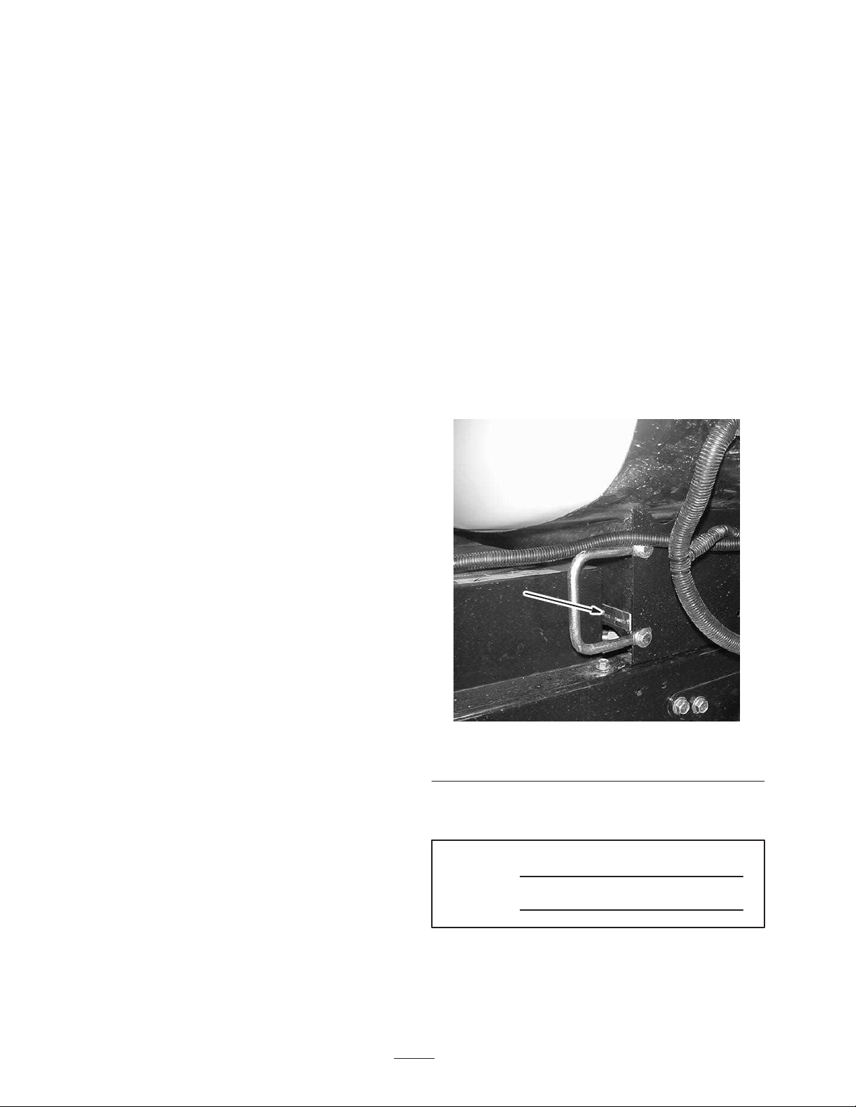
serial numbers of your product ready. Figure 1 illustrates
the location of the model and serial numbers on the
product.
1
Figure 1
1. Location of the model and serial numbers, front left of tank skid
Write the product model and serial numbers in the space
below:
Model No.
Serial No.
This manual identifies potential hazards and has special
safety messages that help you and others avoid personal
injury and even death. Danger, Warning, and Caution are
signal words used to identify the level of hazard.
However, regardless of the hazard, be extremely careful.
W 2005 by The Toro Company
8111 Lyndale Avenue South
Bloomington, MN 55420-1196
Contact us at www.Toro.com
All Rights Reserved
2
Printed in the USA
Page 3
Danger signals an extreme hazard that will cause serious
injury or death if you do not follow the recommended
precautions.
Warning signals a hazard that may cause serious injury or
death if you do not follow the recommended precautions.
TO REDUCE THE POTENTIAL FOR INJURY OR
DEATH, COMPLY WITH THE FOLLOWING
SAFETY INSTRUCTIONS.
Supervisor’s Responsibilities
Caution signals a hazard that may cause minor or
moderate injury if you do not follow the recommended
precautions.
This manual uses two other words to highlight
information. Important calls attention to special
mechanical information and Note: emphasizes general
information worthy of special attention.
Safety
Improper use or maintenance by the operator or owner
can result in injury. To reduce the potential for injury,
comply with these safety instructions and always pay
attention to the safety alert symbol, which means
CAUTION, WARNING, or DANGER—“personal
safety instruction.” Failure to comply with the
instruction may result in personal injury or death.
Safe Operating Practices
Warning
The WORKMAN equipped with a spray system is
an off-highway vehicle only and is not designed,
equipped, or manufactured for use on public
streets, roads, or highways.
The WORKMAN) was designed and tested to offer
safe service when operated and maintained properly.
Although hazard control and accident prevention
partially are dependent upon the design and
configuration of the machine, these factors are also
dependent upon the awareness, concern, and proper
training of the personnel involved in the operation,
maintenance and storage of the machine. Improper use
or maintenance of the machine can result in injury or
death.
This is a specialized utility vehicle designed for
off–road use only. Its ride and handling will have a
different feel than what drivers experience with
passenger cars or trucks. So take time to become
familiar with your WORKMAN) .
Not all of the attachments that adapt to the
WORKMAN) are covered in this manual. See the
specific Operator’s Manual provided with attachment
for additional safety instructions. READ THESE
MANUALS.
• Make sure that operators are thoroughly trained and
familiar with the Operator’s Manual, Training Video,
Engine Manual, and all labels on the Workman
vehicle.
• Be sure to establish your own special procedures and
work rules for unusual operating conditions (e.g.
slopes too steep for vehicle operation). Use the 3rd
High Lockout switch if high speed could result in a
safety or vehicle abuse situation.
Chemical Safety
Warning
Chemicals are hazardous and can injure you,
bystanders, animals, plants, soils, or other
property.
• Carefully read and follow the chemical
manufacturer’s instructions for the safe
preparation, use, and disposal of the chemical.
• Keep chemicals off of your and bystander’s
skin. If contact should occur, wash it off
immediately with clean water and detergent.
• Wear goggles and other protective equipment
as instructed by the chemical manufacturer.
• Obtain proper training before using or handling
chemicals.
• Use the correct chemical for the job.
• Follow the chemical manufacturer’s instructions for
the safe application of the chemical.
• Handle chemicals in a well ventilated area.
• Wear goggles and other protective equipment as
instructed by the chemical manufacturer. Ensure that
as little skin as possible is exposed while using
chemicals.
• Have clean water available especially when filling the
spray tank.
• Do not eat, drink, or smoke while working with
chemicals.
• Always wash your hands and other exposed areas as
soon as possible after finishing the work.
• Properly dispose of unused chemicals and chemical
containers as instructed by the chemical manufacturer
and your local codes.
3
Page 4
• Chemicals and fumes in the tanks are dangerous; never
enter the tank or place your head over or in the
opening.
• Follow all local/state/federal requirements for the
spraying of chemicals.
Before Operating
• Operate the machine only after reading and
understanding the contents of this manual and the
vehicle Operator’s Manual.
• Never allow children to operate the vehicle. Never
allow adults to operate it without proper instructions.
Only trained and authorized persons should operate
this vehicle. Make sure all operators are physically and
mentally capable of operating the vehicle. Anyone
who operates the vehicle should have a motor vehicle
license.
– Fill fuel tank outdoors and to about one inch below
top of tank (bottom of filler neck). Do not overfill.
– Wipe up any spilled gasoline.
• Use only an approved non–metal, portable fuel
container. Static electric discharge can ignite gasoline
vapors in a ungrounded fuel container. Remove the
fuel container from the bed of the vehicle and place on
the ground away from the vehicle before filling. Keep
nozzle in contact with container while filling.
• Check the safety interlock system daily for proper
operation. If a switch should malfunction, replace the
switch before operating machine. After every two
years, replace the interlock switches in the safety
system, whether they are working properly or not.
While Operating
• This vehicle is designed to carry only you, the
operator, and one passenger in the seat provided by
the manufacturer. Never carry any other passengers on
the vehicle.
• Never operate the vehicle when under the influence of
drugs or alcohol.
• Become familiar with the controls and know how to
stop the engine quickly.
• Keep all shields, safety devices and decals in place. If
a shield, safety device or decal is malfunctioning,
illegible, or damaged, repair or replace it before
operating the machine.
• Always wear substantial shoes. Do not operate
machine while wearing sandals, tennis shoes or
sneakers. Do not wear loose fitting clothing or jewelry
which could get caught in moving parts and cause
personal injury.
• Wearing safety glasses, safety shoes, long pants and a
helmet is advisable and required by some local safety
and insurance regulations.
• Keep everyone, especially children and pets, away
from the areas of operation.
• Before operating the vehicle, always check all parts of
the vehicle and any attachments. If something is
wrong, stop using the vehicle. Make sure problem is
corrected before vehicle or attachment is operated
again.
Warning
Engine exhaust contains carbon monoxide, which
is an odorless, deadly poison that can kill you.
Do not run engine indoors or in an enclosed area.
• Operator and passenger should remain seated
whenever the vehicle is in motion. Operator should
keep both hands on steering wheel, whenever possible
and passenger should use hand holds provided. Keep
arms and legs within the vehicle body at all times.
Never carry passengers in the box or on attachments.
Remember your passenger may not be expecting you
to brake or turn and may not be ready.
• Always watch out for and avoid low overhangs such as
tree limbs, door jambs, and over-head walkways.
Make sure there is enough room over head to easily
clear the vehicle, sprayer booms and your head.
• When starting the engine:
– Sit on operator’s seat and ensure parking brake is
engaged.
– Disengage PTO (if so equipped) and return hand
throttle lever to OFF position (if so equipped).
– Move shift lever to NEUTRAL and depress clutch
pedal.
– Keep foot off accelerator pedal.
• Since gasoline is highly flammable, handle it carefully.
– Use an approved gasoline container.
– Do not remove cap from fuel tank when engine is
hot or running.
– Do not smoke while handling gasoline.
– Turn ignition key to START.
• Using the machine demands attention. Failure to
operate vehicle safely may result in an accident, tip
over of vehicle and serious injury or death. Drive
carefully. To prevent tipping or loss of control:
4
Page 5

– Use extreme caution, reduce speed and maintain a
safe distance around sand traps, ditches, creeks,
ramps, and any unfamiliar areas or other hazards.
– Watch for holes or other hidden hazards.
– Use caution when operating vehicle on a steep
slope. Normally travel straight up and down slopes.
Reduce speed when making sharp turns or when
turning on hillsides. Avoid turning on hillsides
whenever possible.
– Use extra caution when operating vehicle on wet
surfaces, at higher speeds or with a full load.
Stopping time will increase with a full load. Shift
into a lower gear before starting up or down a hill.
• If the machine ever vibrates abnormally, stop
immediately, turn engine off, wait for all motion to
stop and inspect for damage. Repair all damage before
resuming operation.
• Before getting off the seat:
– Stop movement of the machine.
– Shut engine off and wait for all movement to stop.
– Set parking brake.
– Remove key from ignition.
Note: Block wheels if machine is on an incline.
– Avoid sudden stops and starts. Do not go from
reverse to forward or forward to reverse without
first coming to a complete stop.
– Do not attempt sharp turns or abrupt maneuvers or
other unsafe driving actions that may cause a loss
of vehicle control.
– Do not pass another vehicle traveling in the same
direction at intersections, blind spots, or at other
dangerous locations.
– When draining, do not let anyone stand behind
vehicle and do not drain liquid on any one’s feet.
– Keep all bystanders away. Before backing up, look
to the rear and assure no one is behind. Back up
slowly.
– Watch out for traffic when near or crossing roads.
Always yield the right of way to pedestrians and
other vehicles. This vehicle is not designed for use
on streets or highways. Always signal your turns or
stop early enough so other persons know what you
plan to do. Obey all traffic rules and regulations.
– Never operate vehicle in or near an area where
there is dust or fumes in the air which are
explosive. The electrical and exhaust systems of
the vehicle can produce sparks capable of igniting
explosive materials.
– If ever unsure about safe operation, STOP WORK
and ask your supervisor.
• Do not use a cab on a Workman vehicle equipped with
a spray system. The cab is not pressurized an dwill not
provide adequate ventilation when used with a sprayer.
The cab will also overload the vehicle when the spray
system tank is full.
• Do not touch engine, transaxle, muffler or muffler
manifold while engine is running or soon after it has
stopped because these areas may be hot enough to
cause burns.
Braking
• Slow down before you approach an obstacle. This
gives you extra time to stop or turn away. Hitting an
obstacle can damage the vehicle and its contents. More
important, it can injure you and your passenger.
• Gross Vehicle Weight (GVW) has a major impact on
your ability to stop and/or turn. Heavy loads and
attachments make a vehicle harder to stop or turn. The
heavier the load, the longer it takes to stop.
• Turf and pavement are slick when they are wet. It can
take 2 to 4 times as long to stop on wet surfaces as on
dry surfaces. If you drive through standing water deep
enough to get the brakes wet, they will not work well
until they are dry. After driving through water, you
should test the brakes to make sure they work properly.
If they do not, drive slowly while putting light pressure
on the brake pedal. This will dry the brakes out.
Operating on Hills and Rough Terrain
Operating the vehicle on a hill may cause tipping or
rolling of the vehicle, or the engine may stall and you
could lose headway on the hill. This could result in
personal injury.
• Do not accelerate quickly or slam on the brakes when
backing down a hill, especially with a load.
• Never drive across a steep hill; always drive straight
up or down or go around the hill.
• If the engine stalls or you begin to lose headway while
climbing a hill, gradually apply the brakes and slowly
back straight down the hill.
• Turning while traveling up or down hills can be
dangerous. If you have to turn while on a hill, do it
slowly and cautiously. Never make sharp or fast turns.
• Heavy loads affect stability. Reduce the weight of the
load and your speed when operating on hills.
5
Page 6

• Avoid stopping on hills, especially with a load.
Stopping while going down a hill will take longer than
stopping on level ground. If the vehicle must be
stopped, avoid sudden speed changes, which may
initiate tipping or rolling of the vehicle. Do not slam
on the brakes when rolling backward, as this may
cause the vehicle to overturn.
• Reduce speed and load when operating on rough
terrain, uneven ground, and near curbs, holes, and
other sudden changes in terrain. Loads may shift,
causing the vehicle to become unstable.
Warning
Sudden changes in terrain may cause abrupt
steering wheel movement, possibly resulting in
hand and arm injuries.
• Reduce your speed when operating on rough
terrain and near curbs.
• Grip the steering wheel loosely around the
perimeter. Keep your hands clear of the
steering wheel spokes.
Loading
• Never work under a sprayer without using tank support
prop rod.
• Make sure all hydraulic line connectors are tight, and
all hydraulic hoses and lines are in good condition
before applying pressure to the system.
• Keep body and hands away from pin hole leaks or
nozzles that eject hydraulic fluid under high pressure.
Use paper or cardboard, not hands, to search for leaks.
Hydraulic fluid escaping under pressure can have
sufficient force to penetrate skin and do serious
damage. If fluid is injected into the skin it must be
surgically removed within a few hours by a doctor
familiar with this form of injury or gangrene may
result.
• Before disconnecting or performing any work on the
hydraulic system, all pressure in system must be
relieved by stopping engine, cycling dump valve from
raise to lower and/or lowering box and attachments. If
box must be in raised position, secure with safety
support.
• To make sure entire machine is in good condition,
keep all nuts, bolts and screws properly tightened.
• To reduce potential fire hazard, keep the engine area
free of excessive grease, grass, leaves and
accumulation of dirt.
The weight of the cargo can change the vehicle center of
gravity and vehicle handling. To avoid loss of control and
personal injury, follow these guidelines:
• Reduce the weight of the load when operating on hills
and rough terrain to avoid tipping or overturning of the
vehicle.
• Liquid loads can shift. This shifting happens most
often while turning, going up or down hills, suddenly
changing speeds, or while driving over rough surfaces.
Shifting loads can cause the vehicle to tip over.
• When operating with a heavy load, reduce your speed
and allow for sufficient braking distance. Do not
suddenly apply the brakes. Use extra caution on
slopes.
• Be aware that heavy loads increase your stopping
distance and reduce your ability to turn quickly
without tipping over.
Maintenance
• Only permit qualified and authorized personnel to
maintain, repair, adjust, or inspect the vehicle.
• Before servicing or making adjustments to the
machine, stop engine, set parking brake and remove
key from ignition to prevent accidental starting of the
engine.
• Empty the tank before tilting or removing sprayer
from vehicle and before storage.
• Before servicing or making adjustments to the
machine, stop the engine, set the parking brake, and
remove the key from the ignition to prevent someone
from accidentally starting the engine.
• If the engine must be running to perform a
maintenance adjustment, keep hands, feet, clothing,
and any parts of the body away from the engine and
any moving parts. Keep everyone away.
• Do not overspeed engine by changing governor
settings. Maximum engine speed is 3650 rpm. To
assure safety and accuracy, have an Authorized TORO
Distributor check maximum engine speed with a
tachometer.
• If major repairs are ever needed or assistance is
required, contact an Authorized TORO Distributor.
• To be sure of optimum performance and safety, always
purchase genuine TORO replacement parts and
accessories. Replacement parts and accessories made
by other manufacturers could be dangerous. Altering
this vehicle in any manner may affect the vehicle’s
operation, performance, durability or its use may result
in injury or death. Such use could void the product
warranty of The TORO Company.
• This vehicle should not be modified without the
TORO Company’s authorization. Direct any inquiries
to The TORO Company, Commercial Division,
Vehicle Engineering Dept., 300 West 82nd St.,
Bloomington, Minnesota 55420–1196. USA
6
Page 7

• Refer to your vehicle’s Operator’s manual for other
maintenance.
7
Page 8
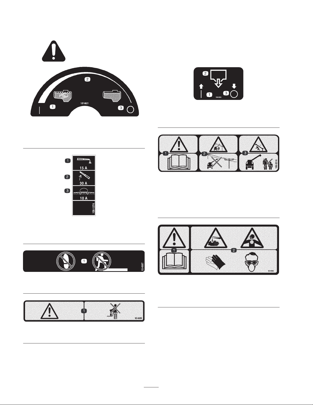
Safety and Instruction Decals
Safety decals and instructions are easily visible to the operator and are located near any
area of potential danger. Replace any decal that is damaged or lost.
107-8621
1. Agitation on
2. Continuous variable
setting
3. Agitation off
1. On
2. Tank drain
1. Warning—read the
Operator’s Manual.
2. Electric shock hazard,
overhead power
lines—stay away from
overhead power lines.
106-5065
3. Off
106-5016
3. Crushing hazard,
boom—keep bystanders a
safe distance from the
machine.
106-1374
1. Foam marker
2. Boom lift
93-6687
1. Do not step here.
93-6689
1. Warning—do not carry passengers.
3. Spray system
93-0688
1. Warning—read the Operator’s Manual.
2. Caustic liquid/chemical burn and toxic gas inhalation
hazards—wear hand, skin, eye, and respiratory protection.
8
Page 9
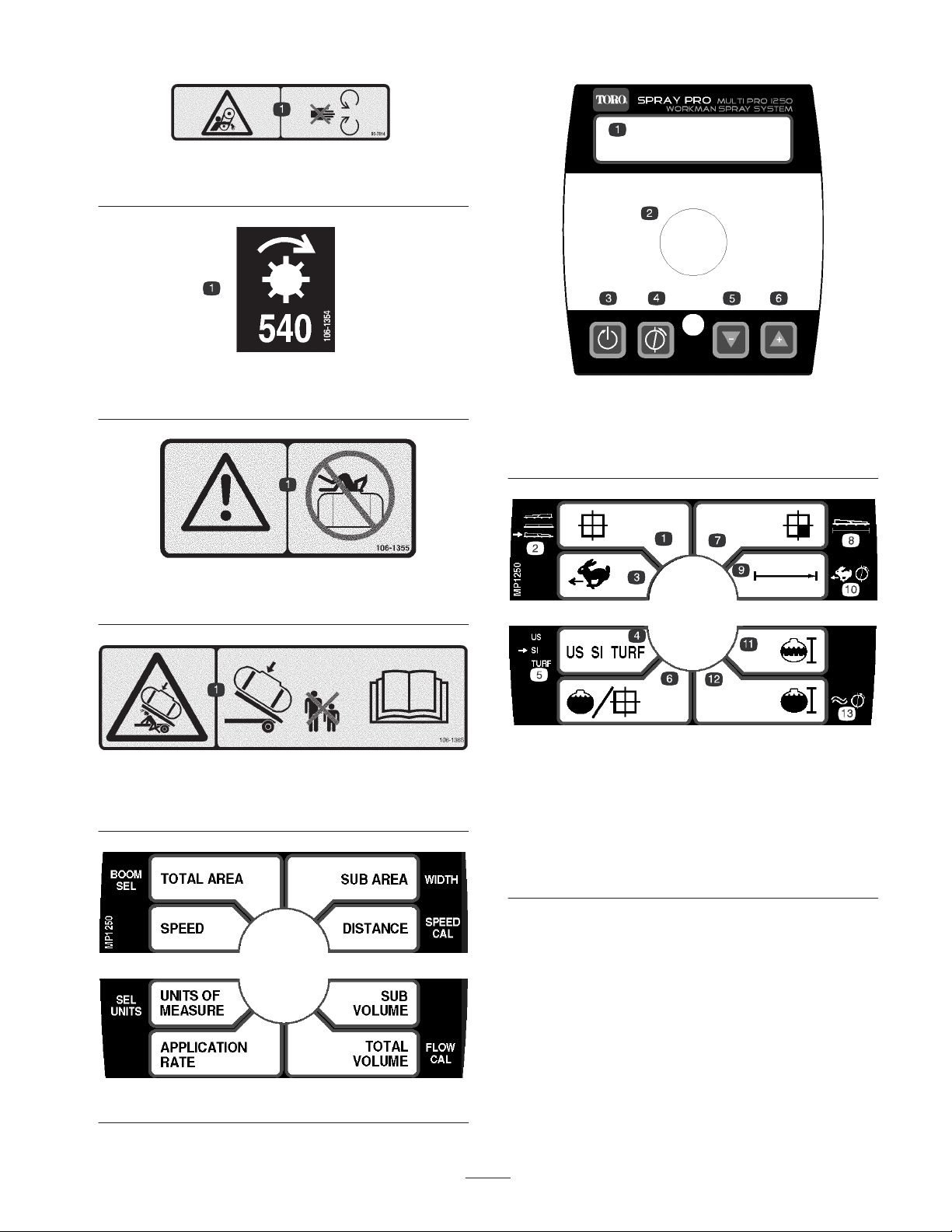
93-7814
1. Entanglement hazard, belt—stay away from moving parts.
106-1354
1. 540 RPM
106-1355
1. Warning—do not enter the tank.
1. LCD screen
2. Selection dial
3. Reset
108-3312
4. Calibrate
5. Decrease
6. Increase
106-1365
1. Crushing hazard, sprayer tank—keep bystanders a safe
distance from the sprayer tank and read the Operator’s Manual.
108-3307
1. Total area
2. Boom select
3. Speed
4. Units of Measure
5. Select units
6. Application rate
7. Sub area
9
108-3309
8. Width
9. Distance
10. Speed calibration
11. Sub volume
12. Total volume
13. Flowmeter calibration
Page 10
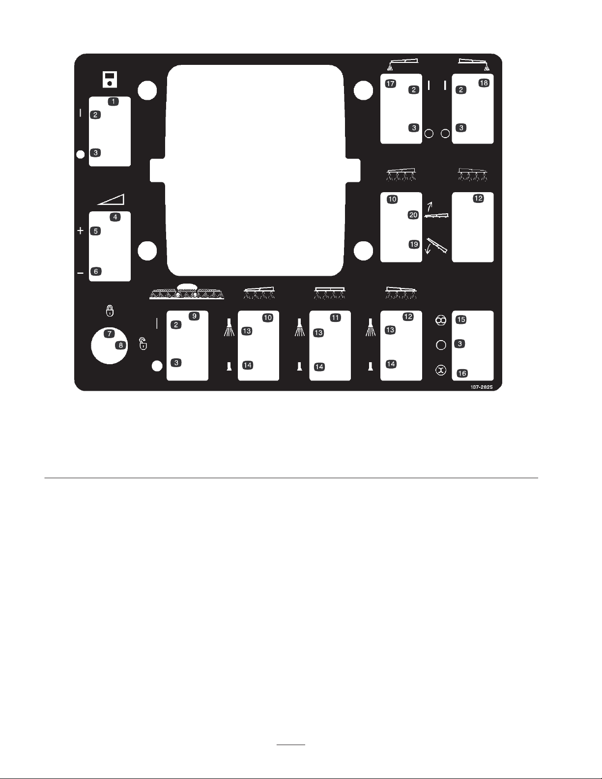
1. Monitor
2. On
3. Off
4. Application rate
5. Increase
6. Decrease
7. Locked-rate switch
8. Unlocked-rate switch
9. Master boom spray
10. Left boom
107-2825
11. Center boom
12. Right boom
13. Spray on
14. Spray off
15. Automatic
16. Manual
17. Left boom foam marker
18. Right boom foam marker
19. Lower the boom.
20. Raise the boom.
10
Page 11

Specifications
Note: Specifications and design are subject to change
without notice.
Spray system base weight 434 lb (197 kg)
Tank capacity 200 US gallons
(757 L)
Overall vehicle length with
the standard spray system
Overall vehicle height with
standard spray system to
the top of the tank
Overall vehicle height with
standard spray system and
the booms stored in the X
pattern
Overall vehicle width with
the standard spray system
and the booms stored in the
X pattern
163 inches (415 cm)
58 inches (147 cm)
72 inches (183 cm)
78 inches (198 cm)
Optional Equipment
The Toro Company has optional equipment and
accessories that you can purchase separately and install on
your WORKMAN. Contact your Authorized Service
Dealer for a complete list of optional equipment that is
currently available for your sprayer.
11
Page 12

Setup
Note: Determine the left and right sides of the machine from the normal operating position.
Note: You will need to purchase RTV silicone sealant before installing this kit.
Contact your Authorized Toro Distributor for information on available accessories. After you install the booms and nozzles
and before using the sprayer for the first time, adjust the boom bypass valves so that the pressure and application rate
remains the same for all booms with one or more booms turned off. Refer to Adjusting the Boom Bypass valves, page 30.
Loose Parts
Note: Use the chart below to verify that all parts have been shipped.
Description Qty. Use
Jack stands
Clevis pins
Cover assembly
Geartooth sensor
Screw, M6 x 1.00 x 12
Spring washer, M6
Fuse Block
Fuse, 10 amp
Fuse, 30 amp
Screw, #10-24 x 3/4 inch
Washer, 7/32 inch
Locknut, #10-24
Electrical harness
Star washer
Wire ties
Decal
Adapter bracket
Bolt, 1/4 x 3/4 inch
Flange nut, 1/4 inch
Control box mount
Bolt, 5/16 x 1 inch
Lock nut, 5/16 inch
4
4
1
1
1
1
1
1
1
2
2
2
1
1
8
1
1
4
4
1
4
4
Preparing the Workman
Installing the vehicle speed sensor
Installing the electrical harness
Installing the control box mount
Support bracket assembly
Socket head bolts, 3/8 x 1 inch
Lock nut, 3/8 inch
Prop rod
Nut
Yoke
Clevis pin
Cotter pin
1
2
2
1
Installing the prop rod assembly
1
1
1
1
12
Page 13

Description UseQty.
Hold-down brackets 2 Installing the attachment hold-down brackets
Radiator cover
Radiator panel
Bolts, 3/8 x 1 inch
Bolts, 1/4 x 3/4 inch
Tank and skid assembly
Clevis pins
Lynch pins
Bolts, 1/2 x 1-1/2 inch
Washers, 1/2 inc
Nuts, 1/2 inch
Knob
J–clips
Bolt, 1/4 x 3/4 inch
Flange nut, 1/4 inch
Spray Pro decal
Boom Assembly
Boom holder assembly, left
Boom holder assembly, right
Center boom
Frame mounting bracket
Bolt, 1/2 x 3 inch
Bolt, 1/2 x 1-1/4 inch
Flange nut, 1/2 inch
Spacer
Boom clamp
Bolt, 3/8 x 1 inch
Washer, 3/8 inch
Flange nut, 3/8 inch
Cable tie
1
1
4
3
1
2
4
2
4
2
1
3
1
1
1
1
1
1
1
2
2
2
4
2
2
2
2
2
4
Installing the radiator cover
Installing the tank skid
Installing the control box
Installing the boom holders and booms
Hose clamps 3 Installing boom hoses
Operator’s Manual 1 Read before operating the machine
Operator’s Video 1 Watch before operating the machine
Parts Catalog 1 Use for ordering replacement parts
Selection Guide 1 Use for selecting nozzles
Predelivery Inspection Form 1 Complete and file in your customer history portfolio
Monitor Decals 1
13
Page 14
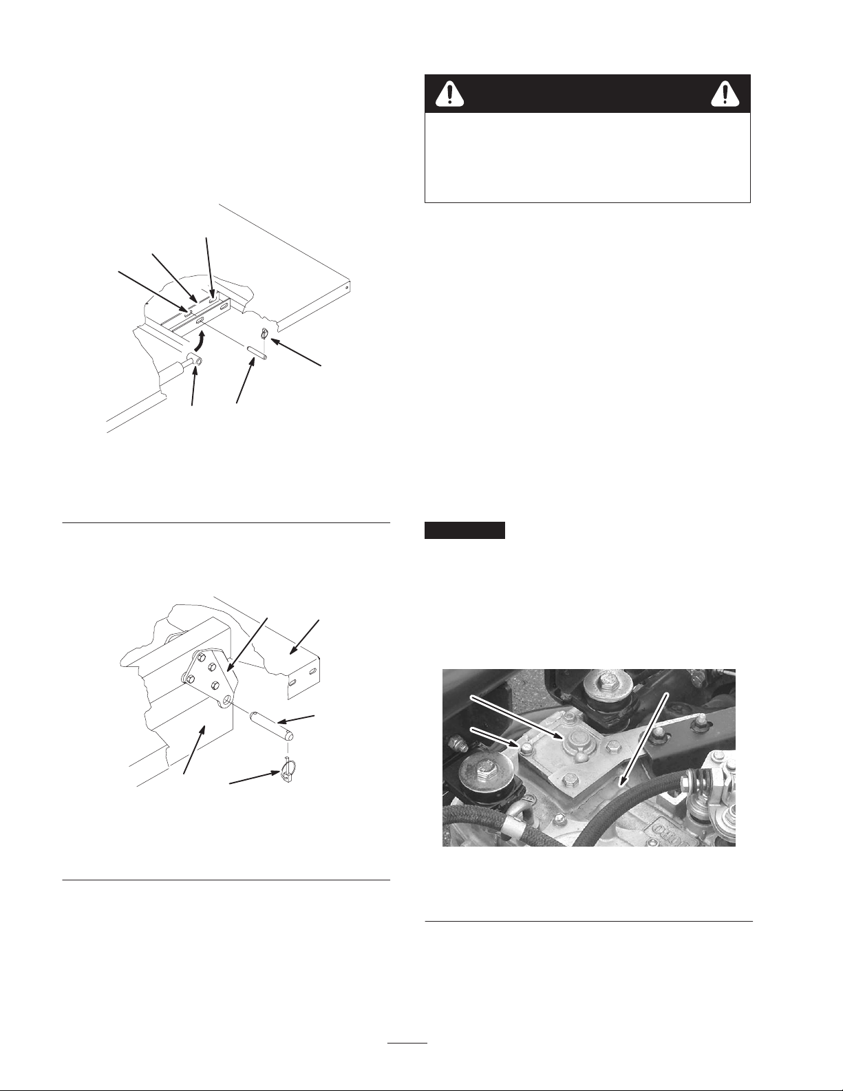
Removing Existing Bed
1. Start the engine. Engage the hydraulic lift lever and
lower the bed until cylinders are loose in slots. Release
the lift lever and the turn off engine.
2. Remove the lynch pins from the outer ends of the
cylinder rod clevis pins (Fig. 2).
Caution
The full bed weighs approximately 210 pounds, so
do not try to install or remove it by yourself. Get
the help of two or three other people or use an
overhead crane.
5
1
6
4
2
3
m–7148
Figure 2
1. Bed mounting plate
2. Cylinder rod end
3. Clevis pin
4. Lynch pin
5. Rear slots (Full bed)
6. Front slots (2/3 bed)
3. Remove the clevis pins securing the cylinder rod ends
to the bed mounting plates by pushing the pins toward
the inside (Fig. 2).
3
1
6. Store the cylinders in storage clips. Engage the
hydraulic lift lock lever on the vehicle to prevent
accidental extension of the lift cylinders.
Preparing the Workman
1. Park the vehicle in a safe work space with access to a
lift.
2. Turn the engine off and remove the key.
3. Disconnect the negative battery cable from the post.
Note: This is a safety precaution since the installation will
require installing an electrical harness.
Installing the Vehicle Speed
Sensor
Important The speed sensor must be installed prior to
the installation of the Power Take Off (PTO) kit. If a PTO
kit was previously installed it must be removed at this
time. See the Installation Instructions from the PTO kit
for more information on removing and installing the PTO
kit.
1. Remove the four bolts securing the cover to the top of
the transaxle housing (Fig. 4).
4
2
5
m–7149
Figure 3
1. Left rear corner of bed
2. Vehicle frame channel
3. Pivot plate
4. Clevis pin
5. Lynch pin
4. Remove the lynch pins and clevis pins securing the
pivot brackets to the frame channels (Fig. 3).
5. Lift the bed off the vehicle.
1
3
2
Figure 4
1. Cover
2. Bolt
3. Transaxle housing
2. Apply RTV sealant to the new cover assembly before
installing it onto the transaxle unit.
14
Page 15
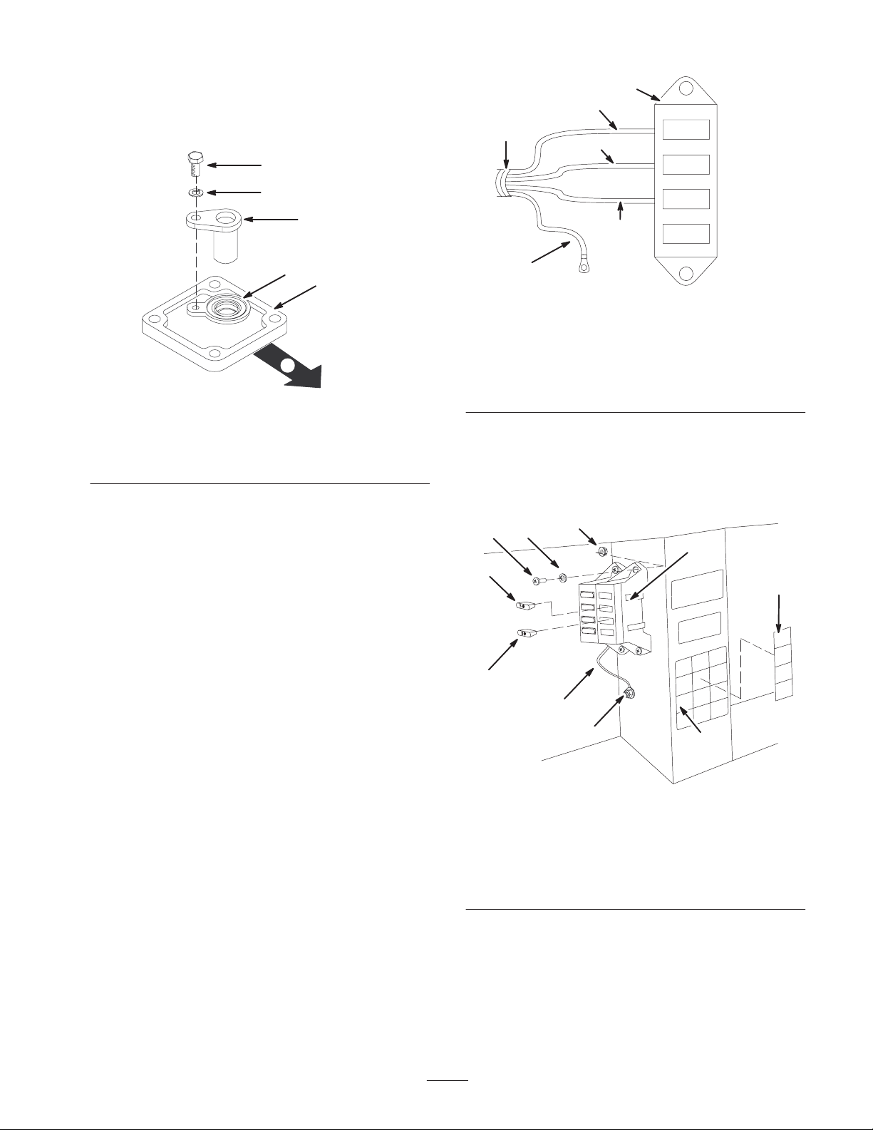
3. Install the new cover assembly to the transaxle using
the four bolts removed in step 1 (Fig. 5). The correct
orientation of the cover will have the seal facing up
and positioned toward the left hand side of the vehicle.
2
2
3
1
4
7
8
3
4
5
1
6
m–7150
Figure 5
1. Cover
2. Screw, M6 x 1.00 x 12
3. Spring washer, M6
4. Geartooth sensor
5. Seal
6. Front of vehicle
4. Install the geartooth sensor using the screw
(M6 x 1.00 x 12) and spring washer (M6) as shown in
figure 5.
5. Install the PTO kit. Refer the Installation Instructions
for more information.
9
5
10
6
m–7218
Figure 6
1. Wiring harness
2. New fuse block
3. Red/black wire
4. Red/white wire
5. Red wire
6. Black ground wire
7. Foam marker fuse slot
8. Boom lift fuse slot
9. Spray system fuse slot
10. Open slot, not used
7. Install the 10 amp fuse to the spray system fuse slot
and attach new fuse block decal (Fig. 7).
8. Install the 30 amp fuse to the boom system fuse slot
(Fig. 7).
34
5
1
10
7
Installing the Electrical
Harness
1. Remove the screws holding the front hood to the
frame. Remove the hood to access the electrical
wiring.
2. Locate the electrical harness and fuse block in loose
parts.
3. Wire the electrical harness to the fuse block by joining
the wires in the harness to the corresponding wire
connectors in the back of the fuse block (Fig. 6).
4. Connect the black ground wire to the existing 1/4 inch
bolt on the vehicle frame, using the star washer
(Fig. 7).
5. Locate an open red power wire coming from the
existing fuse block. Connect it to the matching red
power wire coming from the new fuse block.
6. Install the fuse block and harness to the frame along
side the existing fuse block, using the two screws
(#10-24 x 3/4 inch), two washers (7/32 inch), and two
locknuts (#10-24) as shown in figure 7.
2
8
9
1. Fuse block
2. Fuse, 10 amp
3. Screws, #10-24 x 3/4 inch
4. Washers, 7/32 inch
5. Lock nut, #10-24 inch)
6
m–7151
Figure 7
6. Existing decal
7. New fuse block decal
8. Ground wire, black
9. Star washer and bolt
10. Fuse, 30 amp
15
Page 16
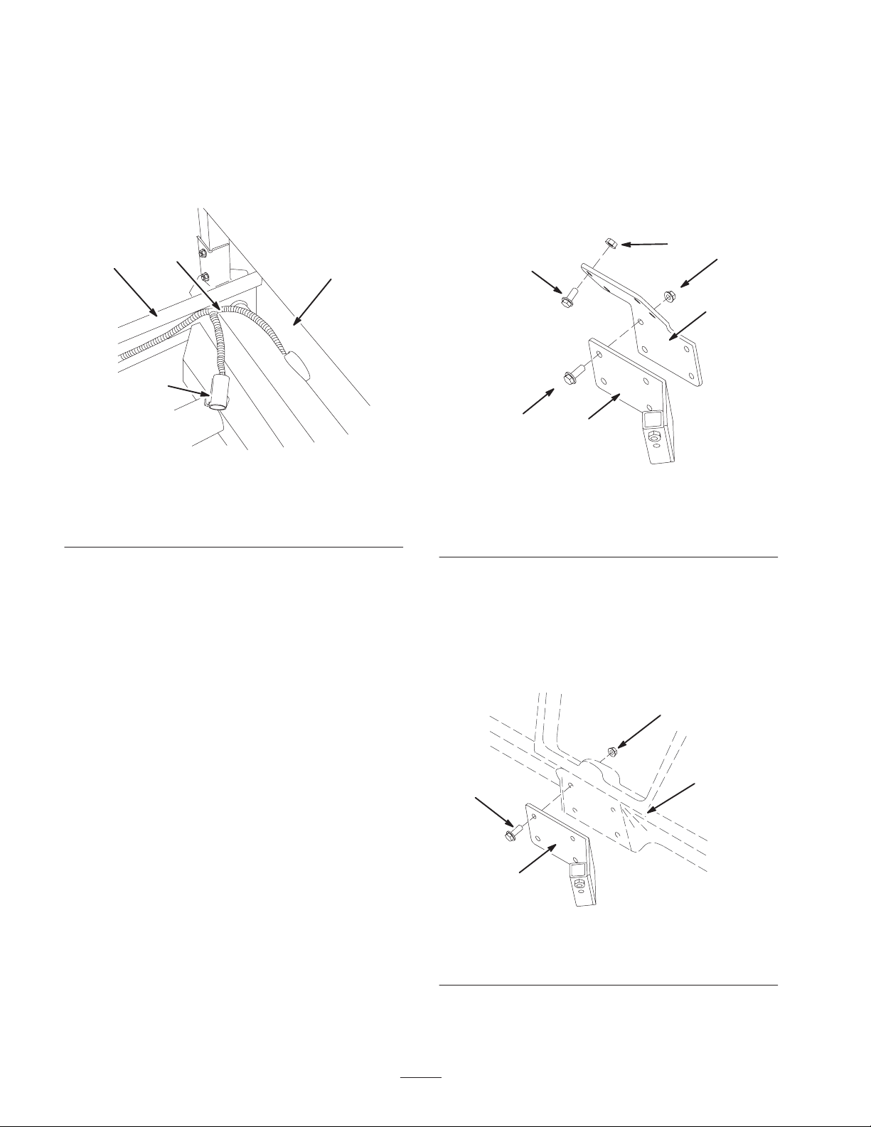
9. Route the wiring harness through the opening in the
floor, under the seat base, and rearward along with the
existing wiring.
10. At the ROPS cover, rear of the seat assembly, route the
wiring harness up from under the seat and above the
frame. Make sure the spray system power connector is
out from underneath the vehicle (Fig. 8).
Installing the Adapter Plate
If you are installing the spray system on a Workman
vehicle with a serial number of 239999999 or lower, you
will need to use the adapter plate, bolts, and nuts included
in the loose parts.
1. Install the adapter plate to the Workman dashboard
using four bolts (1/4 x 3/4 inch) and four flange nuts
(1/4 inch) as shown in figure 9.
3
2
1
4
m–7219
Figure 8
1. ROPS cover
2. Wiring harness
3. Left frame
4. Spray system power
connector
11. Route the harness along the left frame and back to the
speed sensor with the existing wiring (Fig. 8).
12. Install the electrical connector to speed sensor.
13. Use wire ties to secure the harness to the existing
wiring and position it away from any moving parts and
heat sources.
3
6
2
1
5
m–7152
4
Figure 9
1. Adapter plate
2. Bolt, 1/4 x 3/4 inch
3. Flange nut, 1/4 inch
4. Control mount
5. Bolt, 5/16 x 1 inch
6. Lock nut, 5/16 inch
Installing the Control Box Mount
2. Install the control box mount to the Workman
dashboard (or adapter plate) using four bolts
(5/16 x 1 inch) and four lock nuts (5/16 inch) as shown
in figure 10.
14. Install the front hood and secure it with the screws
removed previously.
Installing the Control Box
Mount
On some vehicles the control mount plate is attached to
the dashboard at the same point the hand throttle assembly
is mounted. If the hand throttle kit is installed it must be
separated from the dashboard in order to install the control
mount plate. Refer to the Hand Throttle Kit Operator’s
Manual for directions in removing and installing the hand
throttle assembly.
4
2
3
1
Figure 10
1. Control box mount
2. Dashboard
3. Bolt, 5/16 x 1 inch
4. Lock nut, 5/16 inch
3. Apply the Spray Pro Decal to the monitor. Be sure to
orient the decal as shown in Figure 36.
16
m–7153
Page 17
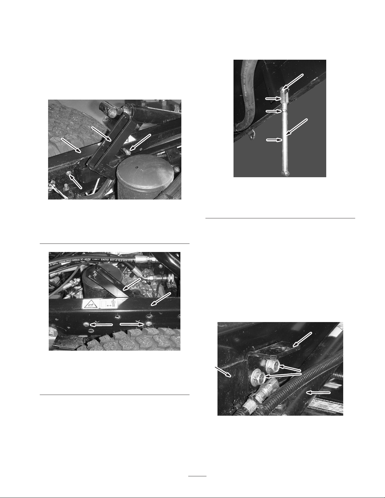
Installing the Prop Rod
Assembly
1. Install the strut support assembly to the inside of the
left frame rail using two socket head bolts
(3/8 x 1 inch) and two lock nuts (3/8 inch) as shown in
figure 11 and 12. Torque the nuts to 30 ± 3 ft⋅lb
(30 ± 4 N⋅m).
3. Install the prop rod assembly on the inside of the rear,
lefthand side of the tank skid frame at the yoke using a
clevis pin and cotter pin (Fig. 13).
5, 6
3
1
2
3
1. Strut support assembly
2. Left frame rail
Figure 11
Inside View
3. Lock nut, 3/8 inch
2
4
3
1
Figure 13
1. Prop rod
2. Jam nut
3. Yoke
4. Prop rod assembly
5. Clevis pin
6. Cotter
4. Bend the cotter pin to secure the prop rod into place.
Installing the Attachment
Hold-down Brackets
1
2
1. Locate and remove the two rear bolts and flange nuts
on the lift cylinder bracket. Retain the fasteners for
later use.
2. Install the attachment hold-down brackets using the
two bolts and flange nuts removed previously
(Fig. 14).
3
Figure 12
Outside View
1. Strut support assembly
2. Left frame rail
3. Socket head bolt,
3/8 x 1 inch
2. Loosely assemble the prop rod, jam nut, and yoke
(Fig. 13).
1
1. Lift cylinder bracket
2. Hold-down bracket
17
2
3
4
Figure 14
Left hand side shown
3. Bolts
4. Lift cylinder
Page 18
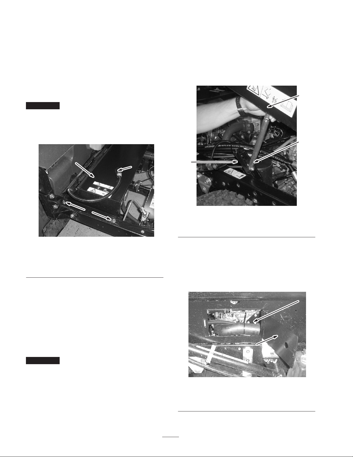
3. Repeat steps to install the hold-down bracket on the
opposite side.
Installing the Radiator Cover
Installing the Tank Skid
1. Using a lift, raise the tank skid assembly and position
over the vehicle frame with the pump and valve
assemblies facing rearward.
1. Locate the spray system power connector on the
wiring harness installed previously.
2. Install the radiator cover assembly over the vehicle’s
radiator (Fig 15).
Important Make sure the spray system power
connecter is routed toward the front of the vehicle and not
trapped under the radiator cover assembly.
3. Secure the cover to the frame using four bolts
(3/8 x 1 inch).
1
3
2
2. Turn the prop rod 90° and guide it through the prop
rod support (Fig 16) as the tank skid is slowly lowered.
1
2
3
Figure 16
1. Tank skid assembly
2. Prop rod, turned 90°
3. Prop rod support
assembly
Figure 15
Left hand side shown
1. Radiator cover assembly
2. Bolt, 3/8 x 1 inch
3. Spray system power
connector
Installing the Radiator Panel on Air
Cooled Vehicles
An additional panel is attached to the front, left of the
radiator cover assembly on all vehicles with air cooled
engines.
4. Install the radiator panel to the radiator cover assembly
by lining the three drilled holes in the panel with the
corresponding holes in the cover assembly.
Important Make sure the spray system power
connecter is routed toward the front of the vehicle and not
trapped under the radiator cover assembly.
5. Secure the panel to the cover using three bolts
(1/4 x 3/4 inch).
3. Once the prop rod is through the support assembly,
turn the prop rod 90° to retain it within the support and
continue to lower the tank skid assembly to the vehicle
frame.
4. Use the access panels on both sides of the tank skid to
check for pinching of any hoses or wiring (Fig 17).
2
1
Figure 17
Right side shown
1. Access panel door 2. Interior of the tank skid
18
Page 19
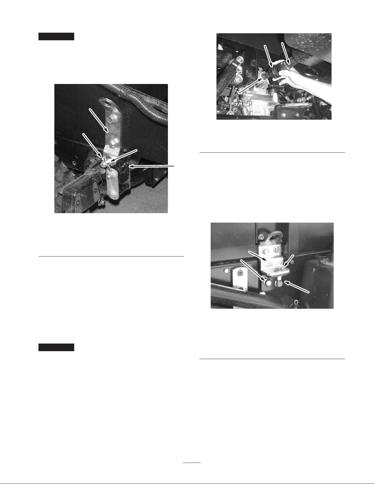
Important If any hoses or wiring on the tank skid
assembly are being pinched or bent, raise the assembly up,
adjust its positioning, and tie items back.
5. Line up the pivot lug at the rear of the tank skid
assembly with the opening at the end of the vehicle
frame (Fig 18).
1
2
1
2
3
2
4
Figure 18
Left side shown
1. Pivot lug
2. Clevis pin, (3/4 inch)
3. Lynch pin
4. Vehicle frame
6. Install a clevis pin (3/4 inch) and two lynch pins to the
pivot lug to secure the tank assembly to frame
(Fig 18).
7. Repeat on the opposite side.
Figure 19
1. Rubber cowling
2. PTO drive shaft
3. PTO output shaft
Finishing the Tank Skid Installation
9. Line up the front mounting brackets with the hold
down brackets installed previously.
10. Secure the tank skid assembly to the frame with a bolt
(1/2 x 1-1/2 inch), two washers (1/2 inch), and a
locknut (1/2 inch) as shown in figure 20.
1
2
3, 4
4, 5
Attaching the Pump Drive
8. Pull rearward on the rubber cowling of the front of the
PTO drive shaft and install the drive shaft onto the
PTO output shaft (Fig. 19).
Important Verify the PTO shaft is secured by making
sure the locking balls are seated in the groove of the
output shaft.
Figure 20
Left side shown
1. Front mounting bracket
2. Hold -down bracket
3. Bolt, 1/2 x 1-1/2 inch
4. Washer, 1/2 inch
5. Locknut, 1/2 inch
11. Repeat these steps for the front mount and hold-down
bracket on the opposite side.
19
Page 20
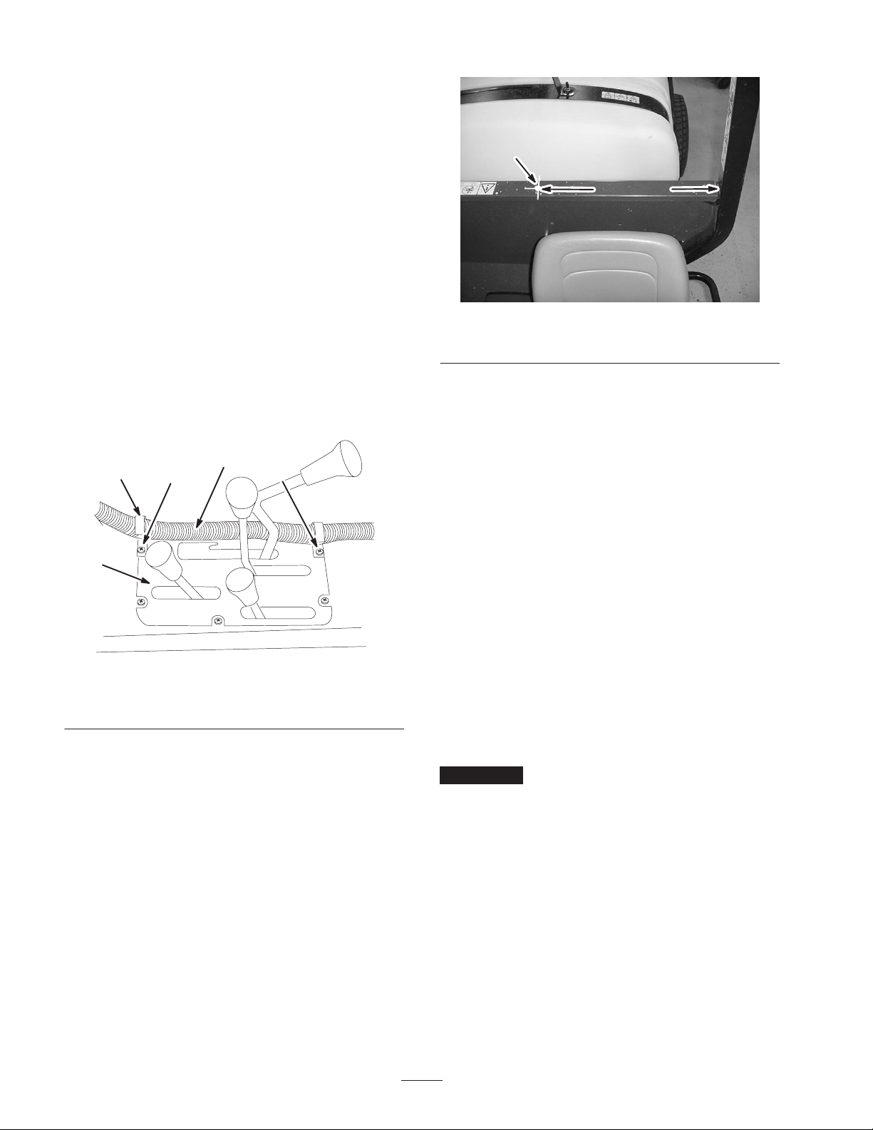
Installing the Control Box
The control box is mounted on the tank skid by a clevis
pin, hair pin and hand knob. It is located on the left side
toward the back.
1
1. Remove the clevis pin, and hair pin securing the
control box to the tank skid.
2. Install the control box, with the controls facing the
driver, to the control mount using the clevis pin and
hair pin removed previously.
3. Install the hand knob to stabilize the control box.
Tighten by hand.
4. Connect the tank skid wiring harness to the spray
system power connector.
Installing the J-Clips
5. Install two J–clips in the center console at the points
located in figure 21 using the existing screws.
3
1
4
2 2
m–7184
20 inches
Figure 22
1. Drill hole, 1/4 inch
7. Secure the control box harness to the console and
ROPS cover using the J-clips.
Installing Boom Holders and
Booms
1. Locate the boom assembly in loose parts. Unfold the
boom extensions and position the boom assembly at
the back of the vehicle with the nozzles facing
rearward.
2. Install the left and right boom holders to the tank skid
frame using two bolts (1/2 x 1-1/4 inches), two frame
mounting brackets, and two flange nuts (1/2 inch) as
shown in Figure 23. Hand tighten fasteners to allow
the installation of the center boom frame.
Figure 21
1. J-clip
2. Existing screws
6. Install a J-clip in the ROPS cover behind the operator
using a bolt (1/4 x 1 inch) and a nut (1/4 inch). The
hole is on the centerline, approximately 20 inches in
from the operator’s side edge of the ROPS cover.
Note: If a hole is not present, one must be drilled. Drill a
1/4 inch hole in the top surface of the cover on the
centerline approximately 20 inches from the edge on the
operator’s side (Fig. 22).
3. Control box harness
4. Center console
3. Install the boom assembly’s center boom frame
between the frame mounting bracket and the tank
sprayer frame. Secure the center boom frame using
two bolts (1/2 x 3 inches), two spacers, and two flange
nuts (1/2 inch) as shown in Figure 23. Hand tighten
fasteners.
Important The spacer is installed between the two
upright tabs on the center boom frame two prevent
warping when the fasteners are torqued.
20
Page 21
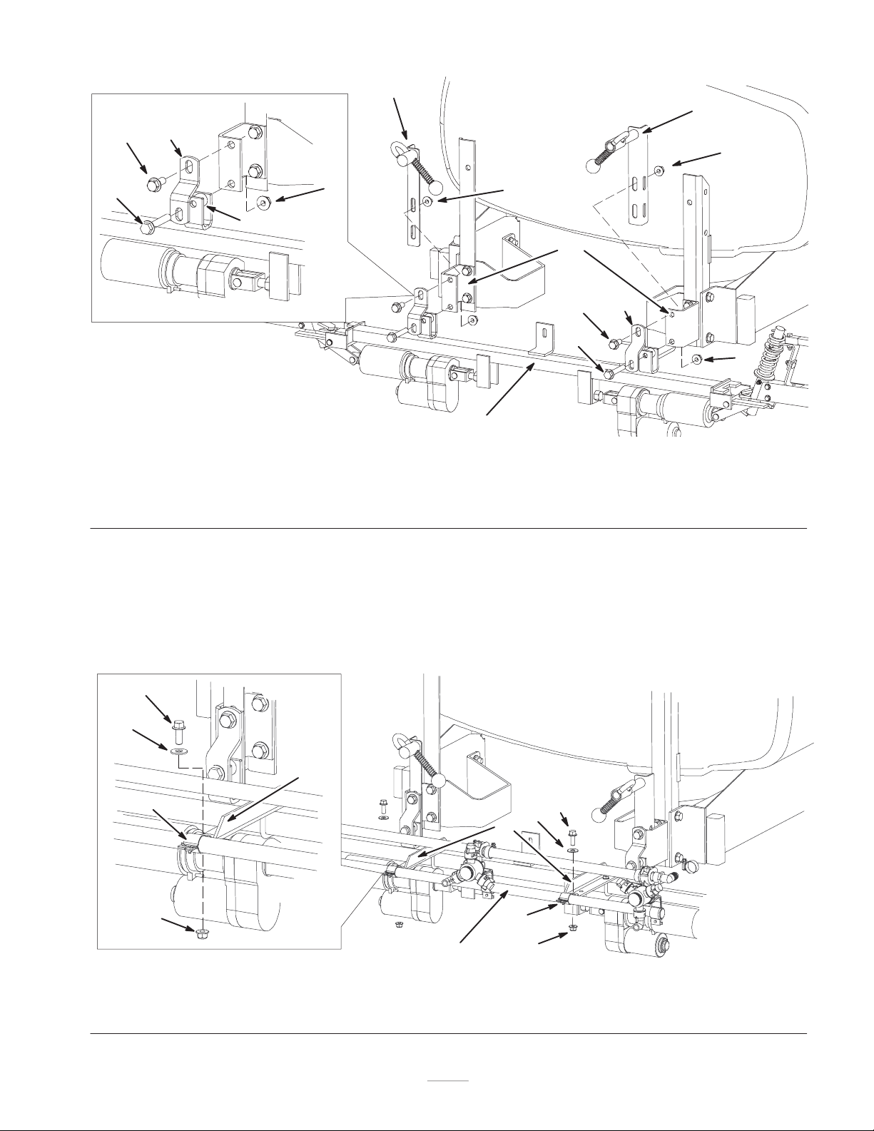
8
9
7
4
6
3
6
5
m–7427
1. Center boom frame
2. Tank sprayer frame brackets
3. Bolt, 1/2 x 3 inch
4. Frame mounting bracket
5. Spacer
4. Adjust the position of the center boom frame so that is
is level. Adjust the boom holders’ height if necessary.
5. Torque all of the fasteners to 105 ft-lb (142 N⋅m).
6. Locate the center boom in loose parts and position it
directly behind the center boom frame with the nozzles
facing rearward.
1
Figure 23
6. Flange nut, 1/2 inch
7. Bolt, 1/2 x 1-1/4 inch
7. Install the center boom to the center frame at the boom
mounting brackets (Fig. 24) using two boom clamps,
two bolts (3/8 x 1 inch), two washers (3/8 inch), and
two flange nuts (3/8 inch).
6
2
7
4
3
6
8. Left boom holder assembly
9. Right boom holder assembly
4
5
3
6
1. Center boom
2. Boom mounting bracket
2
3. Boom clamp
4. Bolt, 3/8 x 1 inch
4
5
2
3
1
6
Figure 24
5. Washer, 3/8 inch 6. Flange nut, 3/8 inch
21
m–7428
Page 22
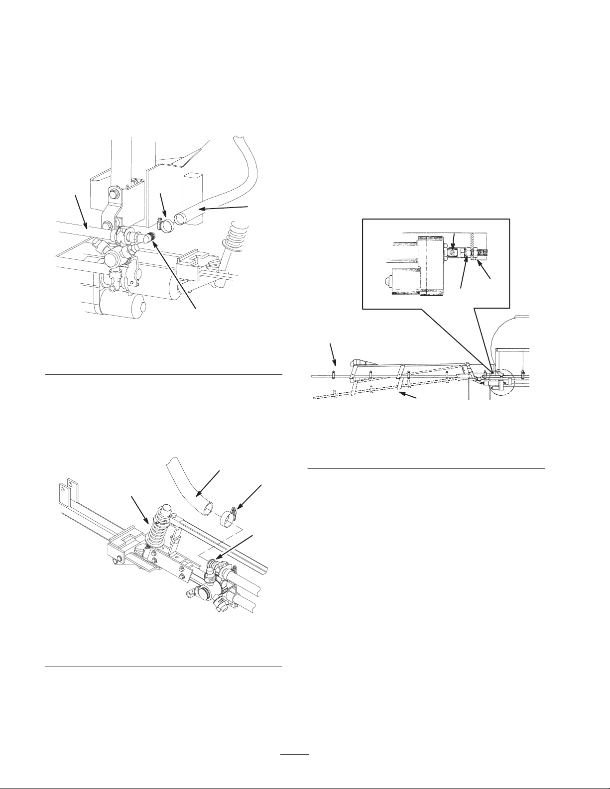
Installing Boom Hoses
1. Use liquid soap to coat the hose barb of the center
boom’s right nozzle turret (Fig. 25).
2. Connect the center boom supply hose to the soaped
barb and fasten it with a hose clamp (Fig. 25).
Greasing the Pivot Arms
The boom pivot arms are not greased at the time of
factory assembly and must be greased before use. Refer to
Greasing the Pivot Arms, page 36, for more information.
Adjusting Extension Booms
1. Loosen the end nut that secures the adjustable clevis to
the boom frame (Fig. 27).
1
3
4
2
m–7429
Figure 25
1. Center boom
2. Hose barb
3. Hose clamp
4. Center boom supply hose
3. Use liquid soap to coat the hose barb of the extension
boom’s nozzle turret closest to the pivot
assembly (Fig. 26).
4. Connect an extension boom supply hose to the soaped
barb and fasten it with a hose clamp (Fig. 26).
3
2
1
2. Move the jam nut as close as possible to the adjustable
clevis. Tighten the end nut to secure the clevis
(Fig. 27).
1
3
2
m-6409
5
4
Figure 27
1. Adjustable clevis
2. Jam nut
3. End nut
4. Boom—adjusted correctly
5. Boom—adjusted
incorrectly
3. Raise the extension boom with the boom actuator. The
actuator should extend fully and ratchet.
m–6632
Figure 26
1. Pivot assembly
2. Hose clamp
3. Boom supply hose
4. Hose barb
5. Repeat steps 3-4 for other boom extension.
4
22
Page 23
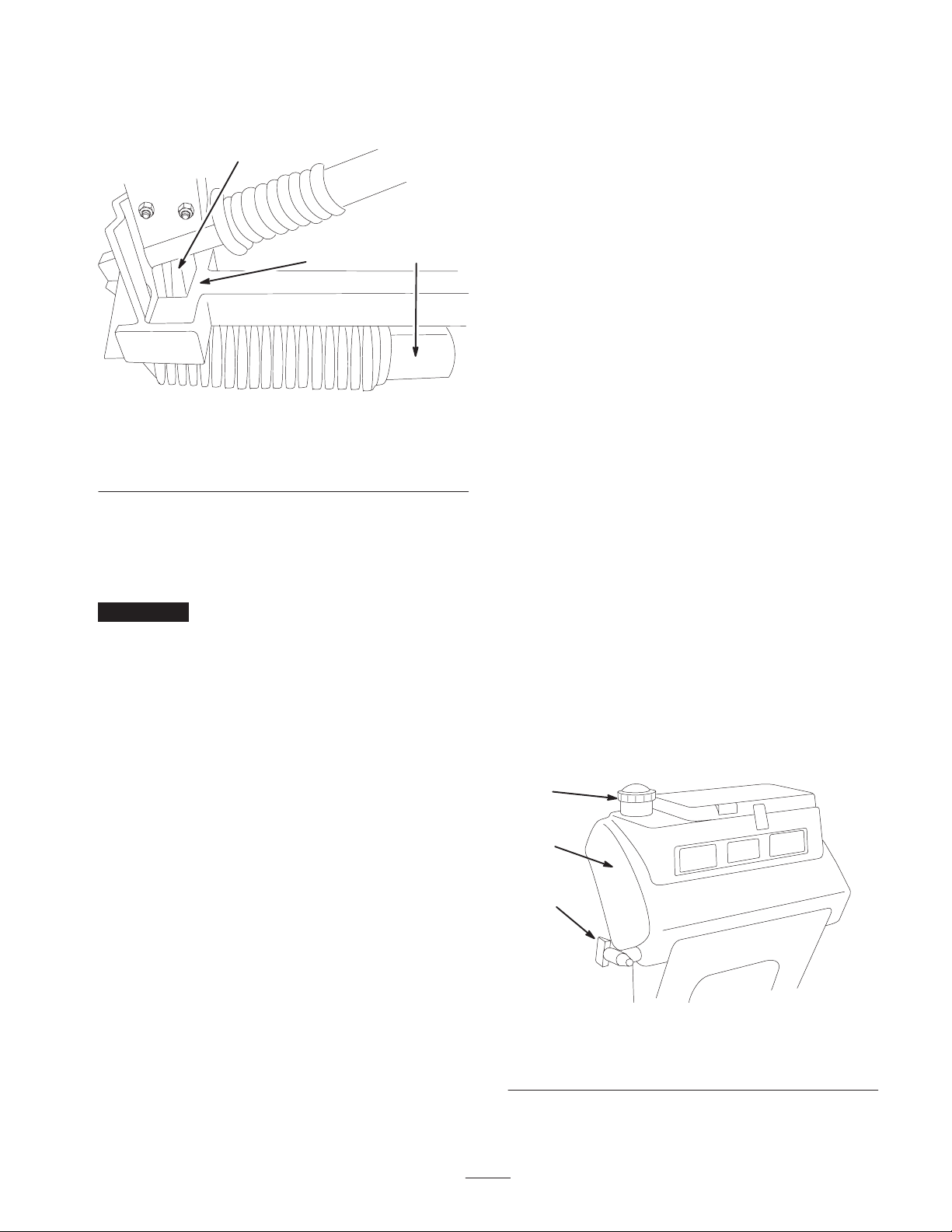
4. With the boom actuator at full extension, the
break-away pivot gusset should just touch the center
boom frame slot (Fig. 28).
1
Installing Nozzles
The nozzles you use to apply your chemicals vary
depending on the rate of application that you need;
therefore, nozzles are not supplied with the kit. To obtain
the correct nozzles for your needs, contact your
Authorized Toro Distributor and be prepared to give them
then following information:
2
Figure 28
1. Break-away pivot gusset
2. Center boom frame slot
5. If necessary, loosen the end nut that secures the
adjustable clevis and adjust the jam nut to allow
correct boom actuator extension. (Fig. 27).
6. Tighten the end nut to secure the clevis adjustment.
Important The booms should not be parallel to the
ground when fully down (Fig. 27). You control each
boom’s orientation to the ground using the switches.
Adjusting the booms in any other manner may damage the
boom or the actuators.
The extension boom nozzles must be spaced 20 inches
apart. Verify this spacing and adjust the nozzles if
necessary.
3. Boom actuator
3
m–7433
• The recommended application rate in US gallons per
acre, US gallons per 1000 sq ft, or liters per hectare.
• The target speed or the vehicle in miles per hour or
kilometers per hour.
• The nozzle spacing (typically 20 inches or 50 cm).
To install a nozzle, complete the following:
1. Thread the nozzle into the nozzle receptacle.
2. Slide the nozzle receptacle over the nozzle fitting on a
turret.
3. Turn the nozzle clockwise to lock the cams on the
receptacle in place.
4. Verify the fan portion of the nozzle faces down.
See the Installation Instructions accompanying the
nozzles for more information.
Before Operating
Filling the Fresh Water Tank
The sprayer is equipped with a fresh water tank (Fig. 29)
for you to wash chemicals off of your skin, eyes, or other
surfaces in the case of accidental exposure. Always fill the
fresh water tank with clean water before handling or
mixing any chemicals.
Actuator Boom Electrical
Connection
1. Connect the connector at the rear of the machine with
the blue and orange wires to the connector on the left
actuator.
2. Connect the connector at the rear of the machine with
the yellow and green wires to the connector on the
right actuator.
3. Seal the connections you made to the actuator wire
connectors with silicone sealant.
4. Secure any loose wires using cable ties.
1
2
3
Figure 29
1. Filler cap
2. Fresh water tank
To open the fresh water tank spigot, turn the lever on the
spigot toward the front of the sprayer.
23
3. Spigot
m–7434
Page 24
Operation
This section covers the operation of the spray system only.
See your Workman Operator’s Manual for information on
vehicle operation.
Note: Determine the left and right sides of the machine
from the normal operating position.
2
1
3
Think Safety First
Please carefully read all of the safety instructions and
decals in the safety section of both this manual and your
vehicle manual. Knowing this information could help you
or bystanders avoid injury.
9
10
4
56 7 8
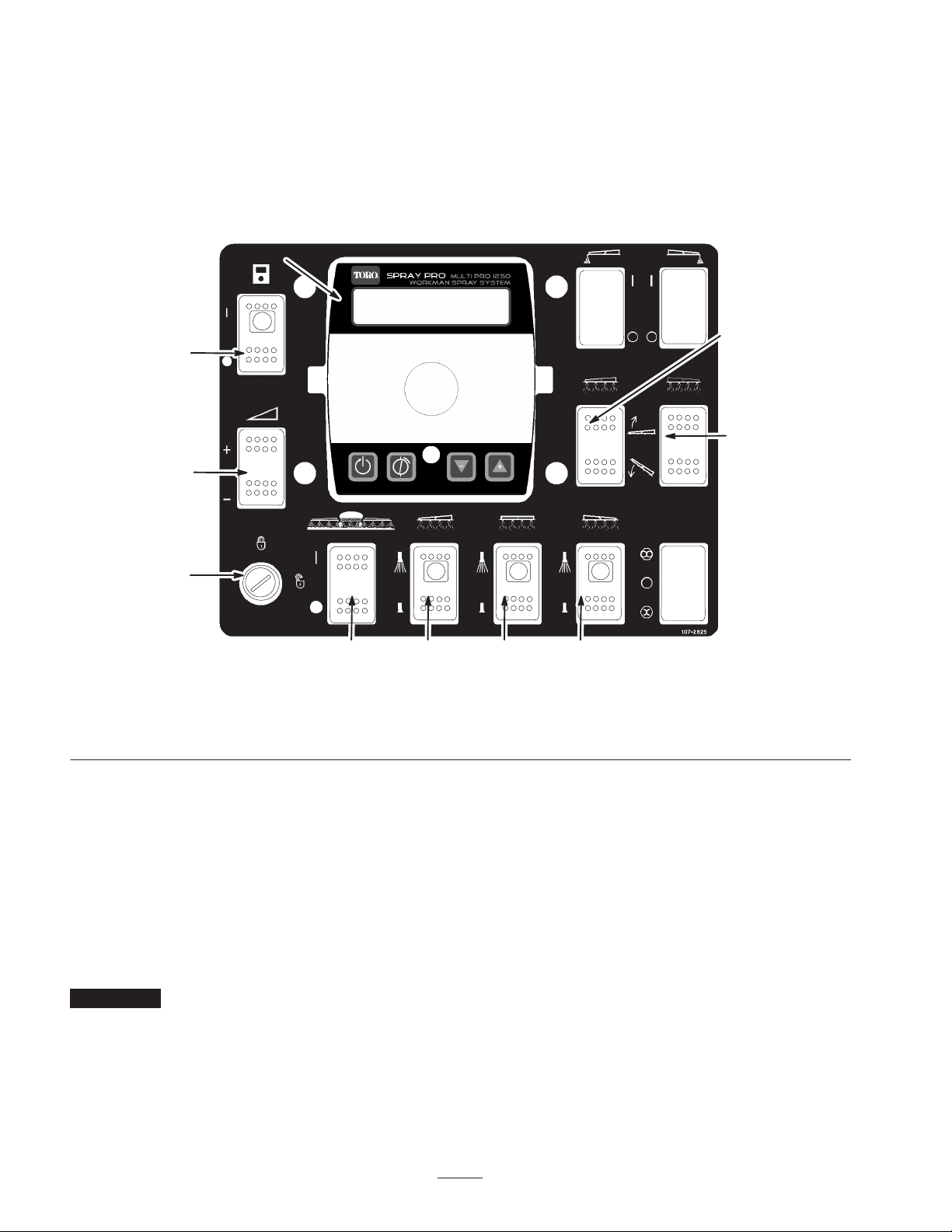
1. Power switch, Spray Pro
monitor
2. Spray Pro monitor
3. Application rate switch
4. Rate lockout key switch
5. Master boom switch
Sprayer Controls and
Components
Spray ProE Monitor Power Switch
The Spray Pro monitor power switch is the On/Off switch
for the monitor. Press the switch to enable or disable the
Spray Pro monitor (Fig. 30). When the switch is turned
on, a light on the switch illuminates. See the Spray Pro
Monitor section on page 27 for information on operating
the monitor.
Important The Spray Pro monitor switch has power
supplied to it at all times. Make sure the switch is turned
off when stored.
Figure 30
6. Left boom switch
7. Center boom switch
8. Right boom switch
Master Boom Switch
The master boom switch allows you to start or stop the
spray operation. Press the switch to enable or disable the
spray system (Fig. 30). When the master switch is off, the
Spray Pro screen reads “Hold.”
Boom Switches
The boom switches are located along the bottom of the
control panel (Fig. 30). Toggle each switch upward to turn
the corresponding boom section on and downward to turn
them off. When the switch is turned on, a light on the
switch illuminates. These switches will only affect the
spray system when the master boom switch is on.
9. Left boom lift switch
10. Right boom lift switch
24
Page 25
Application Rate Switch
The application rate switch is located on the left side of
the control panel (Fig. 30). Press and hold the switch
upward to increase the spray system application rate, or
press and hold it downward to decrease application rate.
Rate Lockout Key Switch
The rate lockout key switch is located on the lower, left
corner of the control pane (Fig. 30). Turn the key
counterclockwise to the locked position to disable the
application rate switch, thereby keeping anyone from
accidentally changing the application rate. Turn the key
clockwise to the unlocked position to enable the
application rate switch.
Boom Lift Switch
1
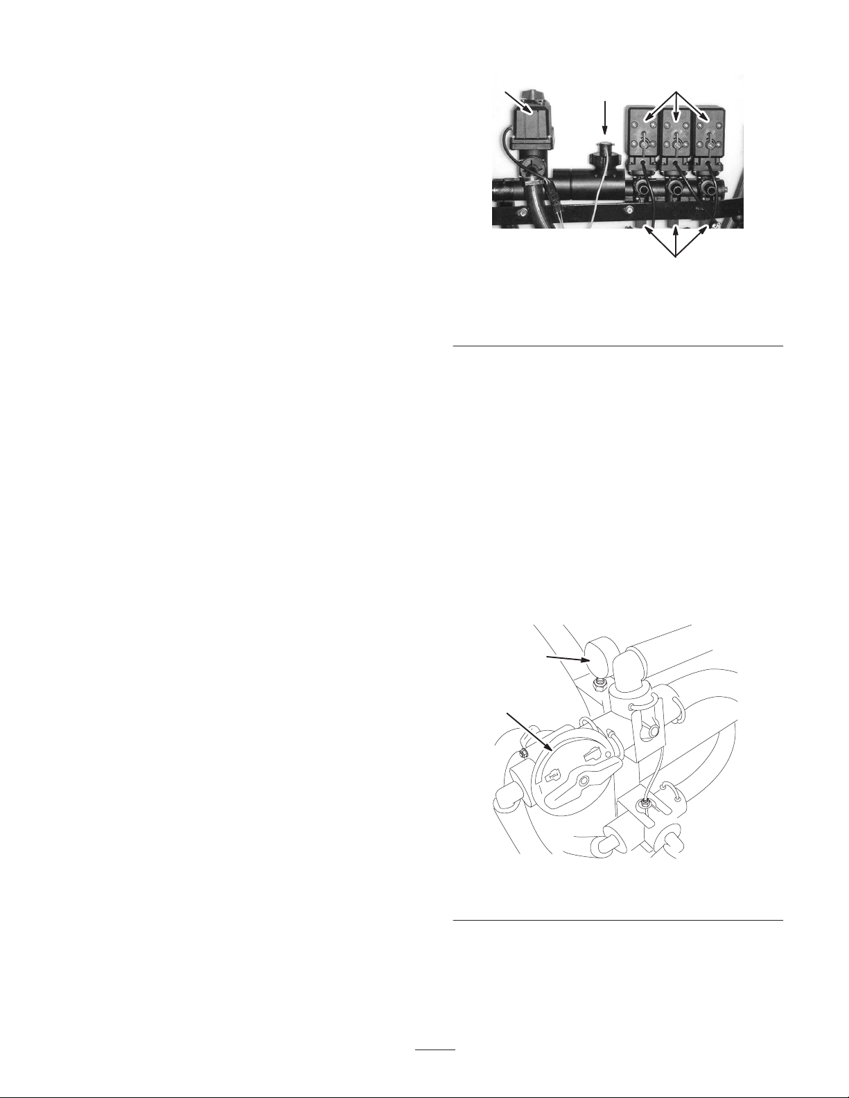
1. Rate control valve
2. Flowmeter
2
Figure 31
3. Boom valves
4. Boom bypass valves
3
4
The electric boom lift switches raise and lower their
respective booms. There is a left and right lift switch.
Press and hold the switch upward to raise the respective
boom, or press and hold the switch downward to lower the
respective boom.
Sonic Boom and Foam Marker Switch
Locations
If you install the sonic boom and/or the foam marker kit,
you will add switches to the control panel for controlling
their operation. The sprayer comes with plastic plugs in
these locations.
Rate Control Valve
This valve, located behind the tank (Fig. 31), controls the
amount of fluid that is routed to the booms by directing
fluid flow to the booms or the bypass hose to the agitation
valve. You can control this valve in two ways: the
application rate switch or manually. To control it
manually, you need to disconnect the wire connector on
the valve, then you can rotate the knob on top of the valve
to manually obtain the desired application rate.
Boom Bypass Valves
The boom bypass valves (Fig. 31) redirect the fluid flow
for a boom to the tank when you turn off the boom
section. You can adjust these valves to ensure that the
boom pressure remains constant no matter how many
booms are on. Refer to Adjusting the Boom Bypass
Valves, page 30.
Agitation Control Valve
This valve is located on the right side of the tank
(Fig. 32). Turn the knob on the valve to the 9 o’clock
position to turn on the tank agitation and to the 3 o’clock
position to turn off the tank agitation.
2
1
Flowmeter
The flowmeter measures the flow rate of the fluid for use
by the Spray Pro™ system (Fig. 31).
Boom Valves
These valves turn the three booms on or off (Fig. 31). If
you do not have a boom installed or do not want a boom
to be able to be turned on, you can manually operate each
valve by disconnecting the wire connector in the valve,
then rotate the knob on the valve clockwise to turn the
valve off or counterclockwise to turn it on.
m–7697
Figure 32
1. Agitation control valve 2. Pressure gauge
For agitation to work, the PTO and clutch must be
engaged, and the engine must be running above an idle. If
you stop the sprayer and need agitation on, place the range
shift lever in the Neutral position, let out the clutch, set
the parking brake, and set the hand throttle (if equipped).
25
Page 26
Pressure Gauge
The pressure gauge is located to the right of the tank
(Fig. 32). This gauge shows the pressure of the fluid in the
system in psi and bar.
Pump
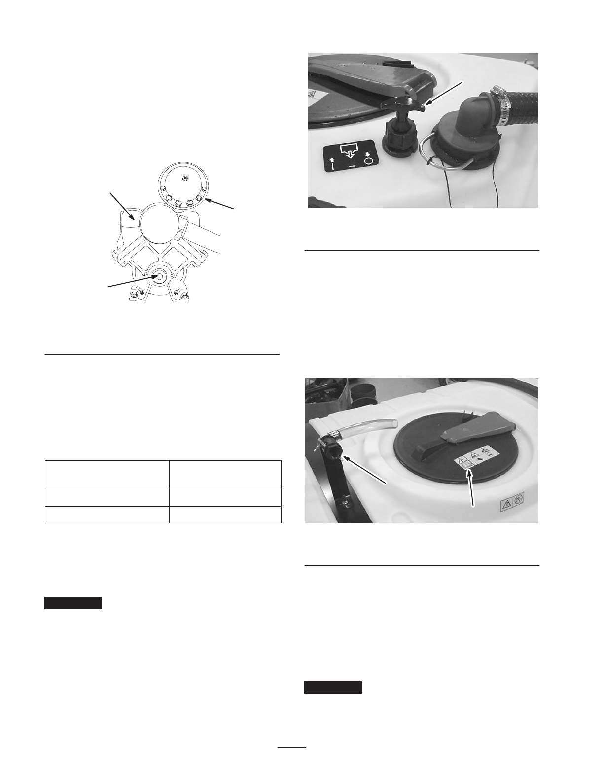
The pump is located near the rear of the vehicle (Fig. 33).
1
3
2
Figure 33
1. Pump
2. Grease fitting
3. Pressure Dampener
1
Figure 34
1. Tank drain handle
Tank Cover
The tank cover is located in the center of the top of the
tank (Fig. 35). To open it, turn off the engine and set the
parking brake, then turn the front half of the cover to the
left and swing it open. You can remove the strainer inside
for cleaning. To seal the tank, replace the strainer if
removed, close the cover, and rotate the front half toward
the right.
Presure Dampener Adjustment
The air pressure in the dampener on the pump is set at
15 psi (1 bar) by the manufacturer. THis is recommended
for nozzle spray pressures between 20 psi (13 bar) and
45 psi (3 bar). If different nozzle pressures are required,
set pressure dampener at pressures indicated.
Nozzle
psi/bar
20–45/1–3 0–15/01
42 and up/3 and up 15–45/1–3
Dampener
psi/bar
Tank Drain Handle
The tank drain handle is located on top of the tank
(Fig. 34). Pull the handle up to drain the tank.
Important Pull the knob gently out until it stops. Do
not pull too hard or you may damage the drain.
2
1
Figure 35
1. Tank cover 2. Anti-siphon fill receptacle
Anti-siphon Fill Receptacle
The anti-siphon fill receptacle, in front of the tank cover,
is a hose receptacle with a threaded fitting and a 90 degree
barbed fitting which you can direct toward the tank
opening (Fig. 35). This receptacle allows you to connect a
water hose and fill the tank without contaminating the
hose and water supply with the chemicals in the tank.
Important Do not allow the hose receptacle to contact
tank fluids. Do not lengthen the hose to allow contact with
the tank fluids.
26
Page 27
Spray Prot Monitor
The Spray Pro monitor displays and monitors various
system performance data such as vehicle speed and
application rates. It does not control the application
rate.
20
US English CE Symbol
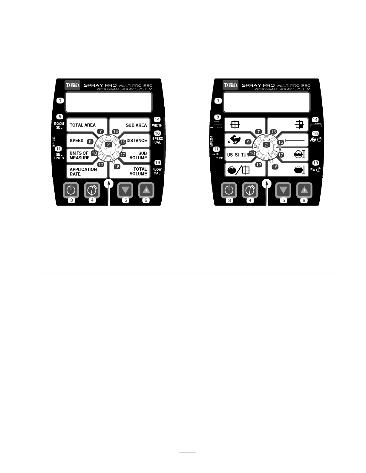
The monitor has an LCD screen that displays the data you
select, a selection dial, and 4 buttons for calibrating the
monitor (Fig. 36).
20
m–XXXX
1. LCD screen
2. Selection dial
3. Reset, calibration button
4. Calibrate, calibration button
5. Decrease, calibration button
6. Increase, calibration button
7. Total area
8. Boom selection
9. Speed
10. Units of measure
Selection Dial
The selection dial contains the following positions:
• Total area
Displays the total acres (US), hectares (SI), or sq feet
(TURF) that you have covered since you last pressed
the Reset calibration button for this setting.
• Speed
Displays the ground speed in miles per hour (if the
Units of Measure is set to US or TURF) or kilometers
per hour (if the Units of Measure is set to SI).
• Units of Measure
Displays the current measurement unit selection as
follows:
– US (United States measuring system)
– SI (metric system)
– TURF (as US but the volumes are in US gallons
per 1000 sq ft instead of US gallons per acre)
Figure 36
11. Select units
12. Application rate
13. Sub Area
14. Width
15. Distance
• Application Rate
• Sub Area
• Distance
• Sub Volume
16. Speed calibration
17. Sub volume
18. Total volume
19. Flowmeter calibration
20. LED
Displays the application rate in US gallons per acre
(US), liters pre hectare (SI), or US gallons per 1000 sq
ft (TURF).
Displays the total acres (US), hectares (SI), or sq feet
(TURF) that you have covered since you last pressed
the Reset calibration button for this setting, without
affecting the Total Area display. If you press the Reset
calibration button, the Sub Volume also resets.
Displays the distance you have traveled in feet (US
and TURF) or meters (SI) since you last pressed the
the Reset calibration button for this setting.
Displays the total volume in US gallons (US and
TURF) or liters (SI) that you have applied since you
last pressed the Reset calibration button for this
27
Page 28

setting, without affecting the Total Volume display. If
you press the Reset calibration button, the Sub Area
also resets.
• Total Volume
4. Turn the selection dial to the Units of Measure
position.
5. Use the Increase or Decrease calibration buttons to
select desired units of measure.
Displays the total volume in US gallons (US and
TURF) or liters (SI) that you have applied since you
last pressed the Reset calibration button for this
setting.
Calibration Buttons
The monitor has the following buttons:
• Reset
Resets the Total Volume, Sub Volume, Distance, Total
Area, and Sub Area display settings to 0.
• Calibrate
Used to enter and exit the calibration mode.
• Decrease
Reduces values displayed on the screen during
calibration.
• Increase
Increases values displayed on the screen during
calibration.
Calibrating the Spray Pro
Monitor
6. Press the Calibrate button until the red light turns off.
You can also exit calibration mode by driving the
sprayer.
Setting the Boom Width
The default settings for the boom widths are 80 inches
(200 cm) for the right and left booms and 60 (150 cm) for
the center boom. This is based on 4 nozzles on the right
and left booms and 3 on the center boom all spaced
20 inches (50.8 cm) apart. If you change the spacing of
the nozzles, you should change the boom width to reflect
your changes as follows:
1. Stop the sprayer and set the parking brake.
2. Set the master boom switch to the Off position. The
monitor displays “HOLD”.
3. Press and hold the Calibrate button until the monitor
displays “CAL HOLD” and the red light on the
monitor illuminates.
4. Turn the selection dial to the Total Area position.
5. Use the Increase or Decrease calibration buttons to
select the boom for which you wish to change the
width, where 1 is the left boom, 2 is the center boom,
and 3 is the right boom.
6. Turn the selection dial to the Sub Area position.
The Spray Pro monitor has a calibration mode that allows
you to change various settings to customize the display
and calibrate the monitor to your needs. You can calibrate
or change the following settings:
• Boom Width
• Units of Measure
• Speed
• Flowmeter
Setting the Units of Measure
The default setting for the units of measure is US. You can
also change the units to SI (metric) or TURF.
1. Stop the sprayer and set the parking brake.
2. Set the master boom switch to the Off position. The
monitor displays “HOLD”.
3. Press and hold the Calibrate button until the monitor
displays “CAL HOLD” and the red light on the
monitor illuminates.
7. Use the Increase or Decrease calibration buttons to
change the boom width as needed.
8. Repeat steps 1 through 7 for the other booms as
needed.
9. Press the Calibrate button until the red light turns off.
You can also exit the calibration mode by driving the
sprayer.
Calibrating the Flowmeter
The Spray Pro comes approximately calibrated for the
flowmeter. Complete the following procedure to fine tune
the flowmeter calibration:
1. Set the parking brake.
2. Fill the tank with enough water to prime and purge the
system.
3. Prime and purge the system.
4. Engage the PTO lever to start the pump.
5. Fill the sprayer tank with a known quantity of water, at
least 100 US gallons (380 L).
28
Page 29

Note: If you park the vehicle on a flat, level surface
and fill the tank until the water over flows out of the
top of the tank, you will have 200 US gallons (760 L).
Note: Do not rely on the marks on the side of the tank
for measuring the water for this procedure. They are
approximate measurements, but not accurate enough
for this calibration.
6. Set all three boom switches to the On position and the
master boom switch to the Off position.
7. Turn the selection dial to the Calibration Volume
position.
8. Press and hold [RESET] until the display reads “0.”
9. Set the master boom switch to the On position and run
the booms until the water level is down to the sump.
Turn the master boom switch off just before the
suction tube draws air, then stop them using the master
boom switch.
10. Compare the volume displayed on the monitor to the
volume of water you put into the tank.
• If the volumes are the same, you do not need to
calibrate the monitor any further.
• If the values are different, continue with the rest of
this procedure.
11. Press and hold [CAL] until the red light on the monitor
illuminates.
The display will alternate between the flowmeter
calibration value (indicated by the word”CAL” on the
monitor) and the calibration volume.
12. When the calibration volume is displayed, use the [+]
or [–] buttons to change it to the amount of water you
put in the tank.
13. When the display begins alternating again, the
flowmeter calibration value will have changed; write
this number down and save it. This is the calibration
value for your vehicle.
14. Press [CAL] until the red light turns off. You can also
exit calibration mode by driving the vehicle.
Calibrating the Speed Sensor
The Spray Pro comes approximately calibrated for the
speed sensor. Complete the following procedure to fine
tune the speed sensor calibration:
1. Check and fill all tires; refer to your Operator’s
Manual on checking the tire pressure.
2. Fill the fresh water tank.
4. Select a straight, flat track of ground that is similar to
your turf conditions.
Note: Using a road or other paved surface could cause an
inaccurate reading when you later drive the sprayer on
turf.
5. Measure 500 feet, marking both the start and end
points.
6. Position the sprayer about 30 feet behind the starting
point.
7. Set the master boom switch to the Off position. The
monitor should display “HOLD”.
8. Turn the selection dial to the Distance position.
9. Press and hold the Reset calibration button until the
display reads “0”.
10. Drive the machine from the start point you marked to
the 500 ft end point. Ensure that you come up to speed
before reaching the start point and do not stop or brake
until after you pass the end point. When you reach the
start point, press the master boom switch to start the
distance tracking with the monitor.
11. When you reach the end point, set the master boom
switch to the Off position to stop the monitor.
12. Look at the distance displayed on the monitor.
• If it reads “500 feet”, you do not need to calibrate
the monitor any further.
• If it does not read “500 feet,” continue with the rest
of this procedure.
13. Set the parking brake.
14. With the selection dial set to the Distance position,
press and hold the Calibrate button until the monitor
displays “CAL HOLD” and the red light on the
monitor illuminates.
The display will alternate between the speed
calibration value and the distance value.
15. When the distance value is displayed, use the Increase
or Decrease calibration buttons to change it to 500
feet.
16. When the display begins alternating again, the speed
calibration value will have changed; write this number
down and save it. This is the calibration value for your
sprayer.
17. Press the Calibrate button until the red light turns off.
You can also exit calibration mode by driving the
sprayer.
3. Fill the sprayer tank half-full of water.
29
Page 30
Resetting an OFL Condition
If the monitor reads “OFL”, it indicates that you have
exceeded the monitor screen dimensions. Press and hold
the Reset calibration button to set the display to 0.
Adjusting the Boom Bypass
Valves
After you install your booms and nozzles and before using
the sprayer for the first time, adjust the boom bypass
valves so that the pressure and application rate remains
the same for all booms when you turn one or more booms
off.
Important The boom bypass valves mus be adjusted
any time nozzles are changed or replaced
Select an open flat area to perform this procedure.
1. Fill the spray tank with clean water.
2. Put the extension booms down, if installed.
3. Set the parking brake and start the engine .
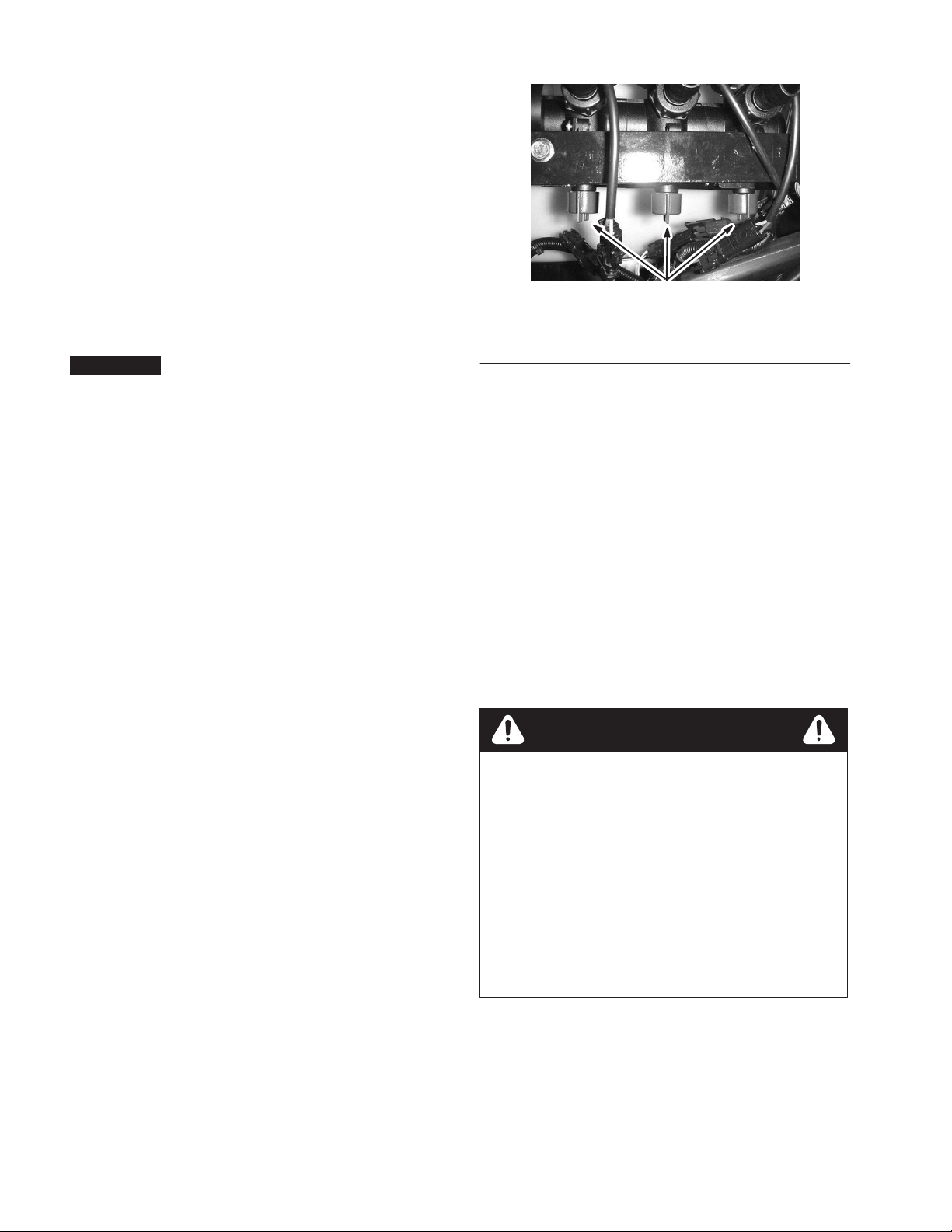
1
Figure 37
1. Boom bypass valves
12. Turn the boom on.
13. Repeat steps 10 through 12 for the other booms.
14. Drive the vehicle at the desired speed while spraying
and turn each boom off individually. The pressure on
the gauge should not change.
4. Place the range selector in the Neutral position.
5. Set the hand throttle.
6. Engage the PTO lever to start the pump.
7. Set all three boom switches and the master boom
switch to the On position.
8. Use the application rate switch to adjust the pressure
as read on the pressure gauge until it is in the range for
the nozzles you installed on the booms (typically
40-50 psi).
9. Record the reading on the pressure gauge.
10. Turn off one of the booms using the appropriate boom
switch.
11. Adjust the boom bypass valve (Fig. 31) under the
boom control valve for the boom you turned off until
the pressure reading on the gauge is the same as it was
in step 8.
Operating the Sprayer
To operate the sprayer you first fill the spray tank, then
apply the solution to the work area, and finally clean the
tank. It is important that you complete all three of these
steps in succession to avoid damaging the sprayer. For
example, do not mix and add chemicals in the spray tank
at night and then spray in the morning. This would lead to
separation of the chemicals and possible damage to the
sprayer components.
Caution
Chemicals are hazardous and can cause personal
injury.
• Read the directions on the chemical labels
before handling the chemicals and follow all
manufacturer recommendations and
precautions.
• Keep chemicals away from your skin. Should
contact occur, wash the affected area
thoroughly with soap and clean water.
• Wear goggles and any other protective
equipment recommended by the chemical
manufacturer.
30
Page 31

Filling the Spray Tank
Important Ensure that the chemicals you will be using
are compatible for use with Viton (see the manufacturer’s
label; it should indicate if it is not compatible). Using a
chemical that is not compatible with Viton will degrade
the o-rings in the sprayer, causing leaks.
1. Stop the sprayer on a level surface, move the range
selector to the Neutral position, stop the engine, and
set the parking brake.
2. Determine the amount of water needed to mix the
amount of chemical you need as prescribed by the
chemical manufacturer.
3. Open the lid on the spray tank.
4. Add 3/4 of the required water to the spray tank using
the anti-siphon fill receptacle.
5. Turn the Spray Pro selection dial to the Application
Rate position and use the application rate switch to
achieve the desired rate.
Note: The vehicle must be moving for the Spray Pro to
calculate the application rate.
6. Set the master boom switch to the On position to begin
spraying.
Note: When the tank is nearly empty, the agitation may
cause foaming in the tank. In this case, turn the agitation
control valve to the 3 o’clock position to turn it off.
Alternatively, you can use an anti-foaming agent in the
tank.
7. When finished spraying, set the master boom switch to
the Off position to turn off all booms, then disengage
the PTO lever.
Important Always use fresh clean water in the spray
tank. Do not pour concentrate into an empty tank.
5. Start the engine, engage the PTO, and set the hand
throttle if equipped.
6. Turn the agitation control valve to the 9 o’clock
position to start agitation in the tank.
7. Add the proper amount of chemical concentrate to the
tank, as directed by the chemical manufacturer.
Important If you are using a wetable powder, mix the
powder with a a small amount of water to form a slurry
before adding it to the tank
8. Add the remaining water to the tank.
Note: Better agitation can be achieved by decreasing the
application rate setting.
Applying Chemicals
Important In order to ensure that your solution
remains well mixed, use the agitation feature whenever
you have solution in the tank. For agitation to work, the
PTO must be engaged and the engine must be running
above an idle. If you stop the vehicle and need agitation
on, place the shift lever in the Neutral position, set the
parking brake, Engage the PTO, engage the clutch, and set
the hand throttle, if equipped.
Note: This procedure assumes that the PTO is engaged
from the Filling the Spray Tank procedure.
1. Swing the booms into position.
2. Set the master boom switches to the Off position. The
Spray Pro monitor displays “HOLD.”
3. Set the individual boom switches, as needed, to the On
positions.
4. Drive to the location where you will be spraying.
Operating Tips
• Do not overlap areas that you have previously sprayed.
• Watch for plugged nozzles. Replace all worn or
damaged nozzles.
• Use the master boom switch to stop the spray flow
before stopping the sprayer. Once stopped, use the
hand throttle, if equipped, to hold the engine speed up
to keep the agitation running.
• You will obtain better results if the sprayer is moving
when you turn the booms on.
• Watch for changes in the application rate that may
indicate that your speed has changed beyond the range
of the nozzles or there is a problem with the spray
system.
Cleaning the Sprayer
Important You must always empty and clean the
sprayer immediately after each use. Failure to do so may
cause the chemicals to dry or thicken in the lines,
clogging the pump and other components.
1. Stop the sprayer, set the parking brake, place the range
selector in the Neutral position, and turn off the
engine.
2. Use the tank drain knob to drain any unused material
from the tank and dispose of it according to local
codes and the material manufacturer’s instructions.
3. Fill the tank with at least 50 US gallons (190 L) of
clean fresh water and close the cover.
Note: You can use a cleaning/neutralizing agent in the
water as needed. On the final rinse, use only clean, clear
water.
4. Start the engine.
31
Page 32

5. With the shift lever in the Neutral position, engage the
PTO, and set the hand throttle.
6. Ensure that the agitation control valve is in the On
position.
7. Set the master boom switch and boom switches to the
On positions to begin spraying.
8. Allow all of the water in the tank to spray out though
the nozzles.
9. Check the nozzles to ensure that they are all spraying
correctly.
10. Set the master boom switch to the Off position,
disengage the PTO, and stop the engine.
11. Repeat steps 3 through 10 at least 2 more times to
ensure that the spray system is fully cleaned.
12. Clean the strainer; refer to Cleaning the Suction
Strainer, page 35.
Important If you used wetable powder chemicals,
clean the strainer after each tank.
13. Using a garden hose, spray off the outside of the
sprayer with clean water.
14. Remove the nozzles and clean them by hand. Replace
damaged or worn nozzles.
Stowing the Boom Extensions
Use the boom restraints to lock the boom extensions in the
X position when you are not spraying.
1. Pivot the left boom extension into the upright position.
Important Do not force the boom extension past the
restraint hook when stowing or you may damage the
extension and nozzles.
2. Push up on the left restraint knob to compress the
spring and extend the hook.
3. With the spring compressed, rotate the hook to catch
the boom extension frame.
4. Release the knob allowing the hook to catch the boom
extension frame and secure it to the boom holder.
5. Repeat steps 1-4 with the right boom extension and
right boom holder.
32
Page 33

Maintenance
Note: Determine the left and right sides of the machine from the normal operating position.
Recommended Maintenance Schedule
Maintenance Service
Interval
8 hours • Clean the suction strainer
50 hours • Lubricate the pump.
100 hours
200 hours
1
More often when using wetable powers
Important Refer to your Workman® and engine operator’s manual for additional maintenance procedures.
Maintenance Procedure
1
• Grease the spray system
• Inspect the pump diaphragm and replace it if necessary.
• Inspect the pressure dampener bladder and replace it if necessary.
• Inspect the pump check valves and replace them if necessary.
• Inspect the O-rings in the vale assemblies and replace them if necessary.
• Check all hoses for wear/cracking.
• Inspect all hose connections for proper attachment.
Daily Maintenance Checklist
Duplicate this page for routine use.
For the week of:
Maintenance Check Item
Check the brake and parking brake
operation.
Check the gear shift/neutral operation.
Check the fuel level.
Check the engine oil level before filling
the tank.
Check the transaxle oil level before
filling the tank.
Inspect the air filter before filling the
tank.
Inspect the engine cooling fins before
filling the tank.
Check any unusual engine noises.
Check any unusual operating noises.
Check the tire pressure.
Check for fluid leaks.
Check the instrument operation.
Mon. Tues. Wed. Thurs. Fri. Sat. Sun.
33
Page 34
For the week of:
Maintenance Check Item
Maintenance Check Item
Check the accelerator operation.
Clean the suction strainer.
Check toe-in.
Lubricate all grease fittings.
Touch up and damaged paint.
1
Immediately after every washing, regardless of the interval listed
1
Notation for Areas of Concern
Inspection performed by:
Item Date Information
1
2
3
4
5
6
7
Sun.Sat.Fri.Thurs.Wed.Tues.Mon.
8
9
10
11
12
If you leave the key in the ignition switch, someone could accidently start the engine and
seriously injure you or other bystanders.
Remove the key from the ignition and disconnect the wire(s) from the spark plug(s) before you
do any maintenance. Set the wire(s) aside so that it does not accidentally contact the spark
plug(s).
Cleaning the Flowmeter
Occasionally, the flowmeter may need to be cleaned to
remove an obstruction, as follows:
1. Remove the retaining cap from the flowmeter body
(Fig. 38).
2. Carefully pull the paddle wheel assembly from the
body.
Caution
3. Use warm water, a soft-bristled brush, and a mild
detergent as necessary to clean the flowmeter body and
paddle wheel. Remove any small metallic debris.
Important Do not use solvents or fuel to clean the
flowmeter.
4. Install the paddle wheel assembly into the flowmeter
body.
34
Page 35
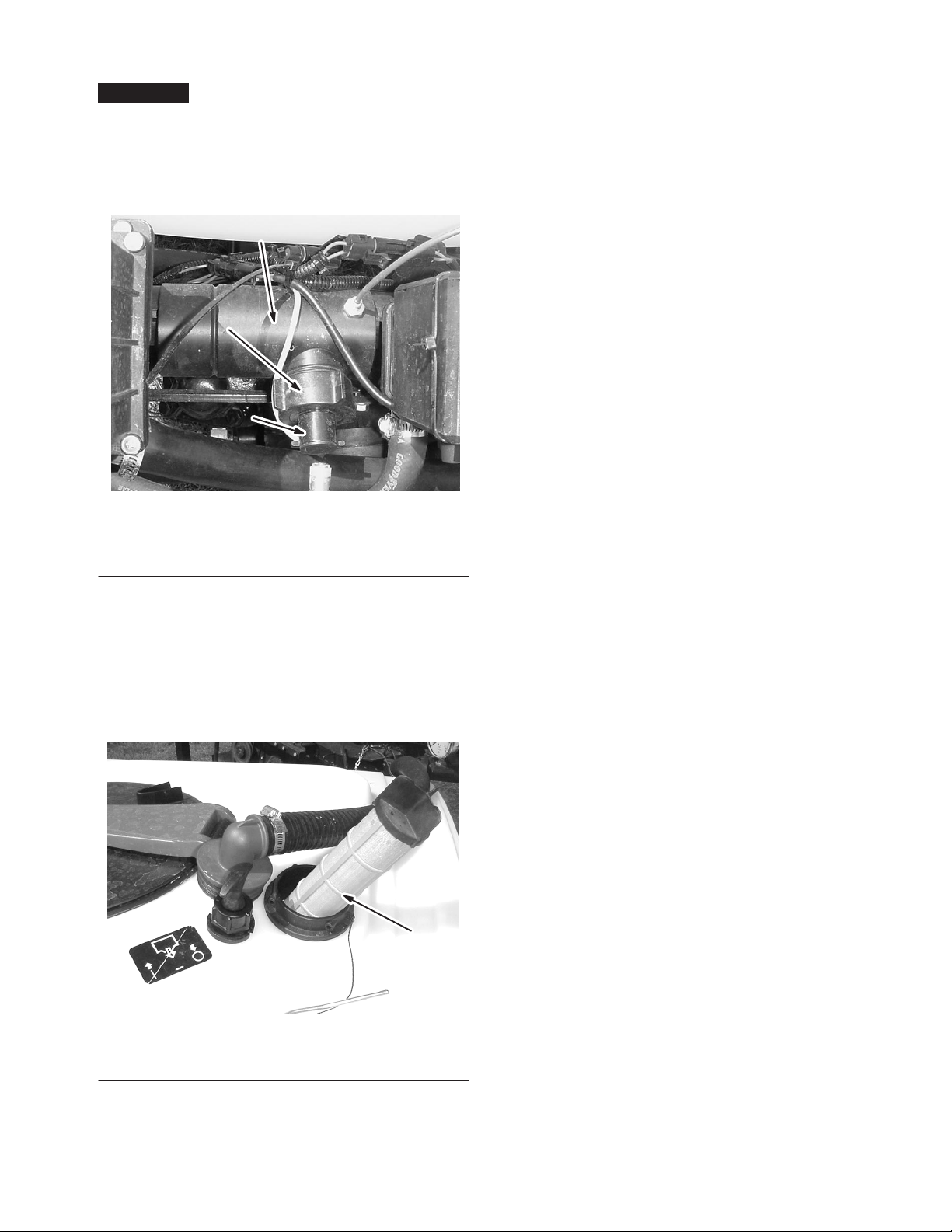
Important The paddle wheel assembly will only fit
into the body one way. Align the pin of the paddle wheel
assembly with the hole in the flowmeter body. Do not
force the paddle wheel assembly into the body in any
other orientation.
5. Install the retaining cap.
3
1
2
Figure 38
1. Retaining cap
2. Paddle wheel assembly
3. Flowmeter body
4. Clean the strainer with clean running water.
5. Replace the strainer, seating it fully into the hole.
6. Connect the hose to the top of the tank and secure it
with the retainer.
Cleaning the Suction Strainer
Clean the suction strainer daily. If you are using wetable
powders, clean it after every tank.
1. Remove the retainer from the red fitting attached to
the large hose on the top of the tank.
1
Figure 39
1. Suction strainer
2. Disconnect the hose from the tank.
3. Pull the strainer out of the hole.
35
Page 36
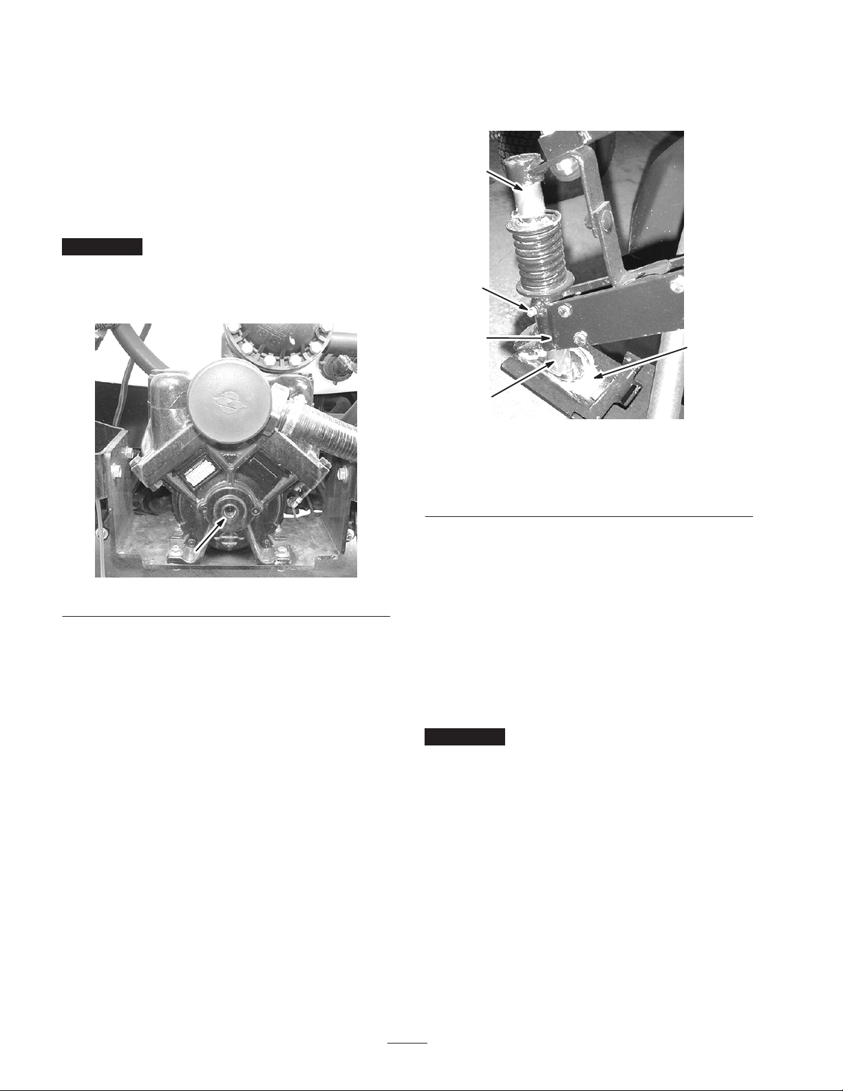
Greasing the Spray System
Lubricate all bearings and bushings after every 100 hours
or once a year, whichever occurs first.
Grease Type: No. 2 General Purpose Lithium Base Grease
1. Wipe the grease fitting clean so that foreign matter
cannot be forced into the bearing or bushing.
2. Pump grease into the bearing or bushing.
Important Only a few pumps of grease are required to
lubricate the system. Do not over grease. Grease will not
purge from the system.
3. Wipe off excess grease.
2. Pump grease into the fitting located below the spring
until grease can be seen coming out of the bottom of
the pivot assembly (Fig. 41).
1
3
Figure 40
Greasing the Pivot Arms
Lubricate the boom extension bearings after every
100 hours or once a year, whichever occurs first.
Grease Type: No. 2 General Purpose Lithium Base
Grease.
1. Manually place grease on the support shaft and within
the ball seat of the hinge plate as shown in Figure 41.
4
1
Figure 41
Left pivot arm shown
1. Support shaft
2. Ball seat of hinge plate
3. Repeat the procedure for opposite pivot arm.
3. Grease fitting
4. Pivot assembly
2
Stowing the Boom Extensions
Use the boom restraints to lock the boom extensions in the
X position when you are not spraying.
Note: If you have the Workman spray system, the left
boom holder holds the left boom and the right boom
holder holds the right boom.
1. Pivot the left boom extension into the upright position.
Important Do not force the boom extension past the
restraint hook when stowing or you may damage the
extension and nozzles.
2. Push up on the right restraint knob to compress the
spring and extend the hook.
3. With the spring compressed, rotate the hook to catch
the boom extension frame.
4. Release the knob allowing the hook to catch the boom
extension frame and secure it to the boom holder.
5. Repeat steps 1-4 with the right boom extension and
left boom holder.
36
Page 37

Storage
1. Position the sprayer on a level surface, set the parking
brake, disengage the PTO, stop the engine, and remove
the ignition key.
2. Clean dirt and grime from the entire machine.
Important You can wash the machine with mild
detergent and water. Do not use high pressure water to
wash the machine. Pressure washing may damage the
electrical system or wash away necessary grease at
friction points. Avoid excessive use of water, especially
near the control panel, lights, engine, and the battery.
3. Clean the spray system; refer to Cleaning the Sprayer,
page 31.
4. Add a rust inhibiting, non-alcohol based, RV
antifreeze solution to the system and run the pump for
a few minutes to circulate it through the system, then
drain the spray system as completely as possible.
5. Inspect the brakes; refer to Workman Operator’s
Manual.
6. Service the air cleaner; refer to Workman Operator ’s
Manual.
7. Grease the sprayer; refer to Greasing the Sprayer,
page 36.
8. Check and tighten all bolts, nuts, and screws. Repair or
replace any part that is damaged.
9. Check the condition of all spray hoses, replacing any
that are damaged or worn.
10. Tighten all hose fittings.
11. Paint all scratched or bare metal surfaces.
Paint is available from your Authorized Service
Dealer.
12. Store the machine in a clean, dry garage or storage
area.
13. Cover the machine to protect it and keep it clean.
Removing the Sprayer
If removing the sprayer from the Workman vehicle, use
the eyelets on the skid frame to lift the sprayer off the
vehicle using straps and an overhead hoist. The wire
harness, prop rod, and PTO shaft must be disconnected.
Lock the jackstands with the clevis pins provided. When
the sprayer is clear of the vehicle, insert the four jack
stands provided and lower the sprayer onto them. The
control box can be stored, using the existing fasteners, to
the left, rear of the tank skid.
37
Page 38

Troubleshooting
py
Troubleshooting the Spray System
Problem Possible Causes Corrective Action
A boom section does not spray.
A boom section does not turn off. 1. The valve is damaged. 1. Stop the spray system and
A boom valve is leaking 1. An O-ring is deteriorated. 1. Stop the spray system and
A pressure drop occurs when you
turn on a boom.
1. Pinched hose 1. Repair or replace the hose.
2. A boom by-pass valve is
improperly adjusted.
3. Damaged boom valve 3. Contact your Authorized
1. The boom bypass valve is
improperly adjusted.
2. There is an obstruction in the
boom valve body.
3. A nozzle is missing. 3. Inspect all nozzles and replace
2. Adjust the boom by-pass
valves.
Service Dealer.
pump and turn off the sprayer.
Remove the retainer from
under the boom valve and pull
out the motor and stem.
Inspect all parts and replace
any that appear damaged.
pump and turn off the sprayer.
Disassemble the valve and
replace the O-rings.
1. Adjust the boom bypass valve.
2. Remove the inlet and outlet
connections to the boom valve
and remove any obstructions.
any if necessary.
Troubleshooting the Spray Pro Monitor
Problem Possible Causes Corrective Action
The monitor does not function.
The Speed is always 0 or is
erratic.
1. The monitor cable is loose or
disconnected.
2. The monitor or cable is
damaged.
3. The monitor fuse is damaged
or ground is loose.
1. The monitor cable is loose. 1. Connect the monitor cable.
2. The speed sensor is not
calibrated correctly.
3. The speed sensor is damaged. 3. Contact your Authorized
38
1. Connect the monitor cable.
2. Contact your Authorized
Service Dealer.
3. Contact your Authorized
Service Dealer.
2. Calibrate the speed sensor.
Service Dealer.
Page 39

Problem Corrective ActionPossible Causes
py
The Distance is inaccurate.
The monitor does not display
Application Rate.
The monitor displays 6553.5 when
in the Application Rate setting.
1. The speed sensor is not
calibrated correctly.
2. The speed sensor is damaged. 2. Contact your Authorized
1. The monitor cable is loose. 1. Connect the monitor cable.
2. The flowmeter is dirty or
clogged.
3. The flowmeter is not calibrated
correctly.
4. The flowmeter is damaged. 4. Contact your Authorized
5. The speed sensor is not
calibrated correctly.
6. The speed sensor is damaged. 6. Contact your Authorized
7. Nozzle size and vehicle speed
configuration is unable to reach
desired application rate.
1. The monitor is not receiving
data from the speed sensor.
1. Calibrate the speed sensor.
Service Dealer.
2. Clean the flowmeter.
3. Calibrate the flowmeter
Service Dealer.
5. Calibrate the speed sensor.
Service Dealer.
7. Use the Nozzle Selection
Guide to choose the correct
configuration of nozzle and
vehicle speed.
1. Contact your Authorized
Service Dealer.
The monitor is erratic in operation. 1. A two-way radio is too close to
the monitor or its cables.
The displayed measurements do
not make sense.
The monitor reads “OFL.” 1. The data has exceeded the
1. The Units of Measurement is
set to a system other than what
you expect.
maximum allowed.
1. Keep two-way radios away
from the monitor and its cables.
1. Check the Units of
Measurement to ensure that it
is set correctly.
1. Press and hold the [Reset]
button to clear the monitor.
39
Page 40

The Toro General Commercial Products Warranty
A Two-Year Limited Warranty
Conditions and Products Covered
The Toro Company and its affiliate, Toro Warranty Company,
pursuant to an agreement between them, jointly warrant your Toro
Commercial Product (“Product”) to be free from defects in
materials or workmanship for two years or 1500 operational
hours*, whichever occurs first. Where a warrantable condition
exists, we will repair the Product at no cost to you including
diagnosis, labor, parts, and transportation. This warranty begins
on the date the Product is delivered to the original retail purchaser.
* Product equipped with hour meter
Instructions for Obtaining Warranty Service
You are responsible for notifying the Commercial Products
Distributor or Authorized Commercial Products Dealer from whom
you purchased the Product as soon as you believe a warrantable
condition exists.
If you need help locating a Commercial Products Distributor or
Authorized Dealer, or if you have questions regarding your
warranty rights or responsibilities, you may contact us at:
Toro Commercial Products Service Department
Toro Warranty Company
8111 Lyndale Avenue South
Bloomington, MN 55420-1196
952-888-8801 or 800-982-2740
E-mail: [email protected]
Owner Responsibilities
As the Product owner, you are responsible for required maintenance and adjustments stated in your operator’s manual. Failure
to perform required maintenance and adjustments can be grounds
for disallowing a warranty claim.
Items and Conditions Not Covered
Not all product failures or malfunctions that occur during the
warranty period are defects in materials or workmanship. This
express warranty does not cover the following:
• Product failures which result from the use of non-Toro
replacement parts, or from installation and use of add-on,
modified, or unapproved accessories
• Product failures which result from failure to perform required
maintenance and/or adjustments
• Product failures which result from operating the Product in an
abusive, negligent or reckless manner
• Parts subject to consumption through use unless found to be
defective. Examples of parts which are consumed, or used up,
during normal Product operation include, but are not limited to,
blades, reels, bedknives, tines, spark plugs, castor wheels,
tires, filters, belts, and certain sprayer components such as
diaphragms, nozzles, and check valves, etc.
• Failures caused by outside influence. Items considered to be
outside influence include, but are not limited to, weather,
storage practices, contamination, use of unapproved coolants,
lubricants, additives, or chemicals, etc.
• Normal “wear and tear” items. Normal “wear and tear” includes,
but is not limited to, damage to seats due to wear or abrasion,
worn painted surfaces, scratched decals or windows, etc.
Parts
Parts scheduled for replacement as required maintenance are
warranted for the period of time up to the scheduled replacement
time for that part.
Parts replaced under this warranty become the property of Toro.
Toro will make the final decision whether to repair any existing part
or assembly or replace it. Toro may use factory remanufactured
parts rather than new parts for some warranty repairs.
General Conditions
Repair by an Authorized Toro Distributor or Dealer is your sole
remedy under this warranty.
Neither The Toro Company nor Toro Warranty Company is
liable for indirect, incidental or consequential damages in
connection with the use of the Toro Products covered by this
warranty, including any cost or expense of providing substitute equipment or service during reasonable periods of
malfunction or non-use pending completion of repairs under
this warranty. Except for the Emissions warranty referenced
below, if applicable, there is no other express warranty. All
implied warranties of merchantability and fitness for use are
limited to the duration of this express warranty.
Some states do not allow exclusions of incidental or consequential
damages, or limitations on how long an implied warranty lasts, so
the above exclusions and limitations may not apply to you.
This warranty gives you specific legal rights, and you may also
have other rights which vary from state to state.
Note regarding engine warranty: The Emissions Control System
on your Product may be covered by a separate warranty meeting
requirements established by the U.S. Environmental Protection
Agency (EPA) and/or the California Air Resources Board (CARB).
The hour limitations set forth above do not apply to the Emissions
Control System Warranty. Refer to the Engine Emission Control
Warranty Statement printed in your operator’s manual or contained in the engine manufacturer’s documentation for details.
Countries Other than the United States or Canada
Customers who have purchased Toro products exported from the United States or Canada should contact their Toro Distributor (Dealer)
to obtain guarantee policies for your country, province, or state. If for any reason you are dissatisfied with your Distributor’s service or
have difficulty obtaining guarantee information, contact the Toro importer. If all other remedies fail, you may contact us at Toro Warranty
Company.
Part No. 374-0031 Rev. C
 Loading...