

Page 1
FormNo.3431-106RevA
Workman
®
HDX-AutoUtility
Vehicle
ModelNo.07390—SerialNo.403430001andUp
ModelNo.07390TC—SerialNo.403430001andUp
Registeratwww.T oro.com.
OriginalInstructions(EN)
*3431-106*A
Page 2
ThisproductcomplieswithallrelevantEuropean
directives;fordetails,pleaseseetheseparateproduct
specicDeclarationofConformity(DOC)sheet.
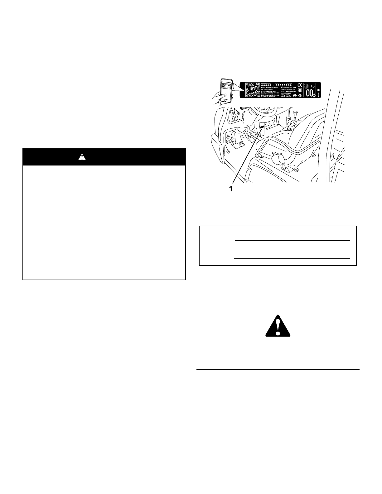
Figure1identiesthelocationofthemodelandserial
numbersontheproduct.Writethenumbersinthe
spaceprovided.
ItisaviolationofCaliforniaPublicResourceCode
Section4442or4443touseoroperatetheengineon
anyforest-covered,brush-covered,orgrass-covered
landunlesstheengineisequippedwithaspark
arrester,asdenedinSection4442,maintainedin
effectiveworkingorderortheengineisconstructed,
equipped,andmaintainedforthepreventionofre.
Theenclosedengineowner'smanualissupplied
forinformationregardingtheUSEnvironmental
ProtectionAgency(EPA)andtheCaliforniaEmission
ControlRegulationofemissionsystems,maintenance,
andwarranty.Replacementsmaybeorderedthrough
theenginemanufacturer.
WARNING
CALIFORNIA
Proposition65Warning
Theengineexhaustfromthisproduct
containschemicalsknowntotheStateof
Californiatocausecancer,birthdefects,
orotherreproductiveharm.
Batteryposts,terminals,andrelated
accessoriescontainleadandlead
compounds,chemicalsknownto
theStateofCaliforniatocause
cancerandreproductiveharm.Wash
handsafterhandling.
Important:Withyourmobiledevice,youcan
scantheQRcodeontheserialnumberdecal(if
equipped)toaccesswarranty,parts,andother
productinformation.
g239323
Figure1
1.Modelandserialnumberlocation
ModelNo.
SerialNo.
Thismanualidentiespotentialhazardsandhas
safetymessagesidentiedbythesafety-alertsymbol
(Figure2),whichsignalsahazardthatmaycause
seriousinjuryordeathifyoudonotfollowthe
recommendedprecautions.
Introduction
Thisutilityvehicleisintendedtobeprimarilyused
off-highwaytotransportpeopleandmaterialloads.
Usingthisproductforpurposesotherthanitsintended
usecouldprovedangeroustoyouandbystanders.
Readthisinformationcarefullytolearnhowtooperate
andmaintainyourproductproperlyandtoavoid
injuryandproductdamage.Youareresponsiblefor
operatingtheproductproperlyandsafely .
Visitwww.Toro.comforproductsafetyandoperation
trainingmaterials,accessoryinformation,helpnding
adealer,ortoregisteryourproduct.
Wheneveryouneedservice,genuineToroparts,or
additionalinformation,contactanAuthorizedService
DistributororT oroCustomerServiceandhavethe
modelandserialnumbersofyourproductready.
©2019—TheToro®Company
8111LyndaleAvenueSouth
Bloomington,MN55420
Figure2
Safety-alertsymbol
Thismanualuses2wordstohighlightinformation.
Importantcallsattentiontospecialmechanical
informationandNoteemphasizesgeneralinformation
worthyofspecialattention.
2
g000502
Contactusatwww.Toro.com.
PrintedintheUSA
AllRightsReserved
Page 3

Contents
Safety.......................................................................4
GeneralSafety...................................................4
SafetyandInstructionalDecals..........................5
Setup.......................................................................11
1InstallingtheSteeringWheel..........................12
2ConnectingtheBattery..................................12
3CheckingtheFluidLevelsandTire
Pressure.......................................................13
4InstallingtheRollBar.....................................13
5ConnectingtheCVT-IntakeDuct....................13
6BurnishingtheBrakes....................................14
ProductOverview...................................................15
Controls...........................................................15
ControlPanel................................................17
InstrumentCluster.........................................17
Specications..................................................20
Attachments/Accessories.................................20
BeforeOperation.................................................21
BeforeOperationSafety...................................21
PerformingDailyMaintenance..........................21
CheckingtheTirePressure...............................21
AddingFuel......................................................22
BreakinginaNewMachine..............................22
CheckingtheSafety-InterlockSystem..............23
DuringOperation.................................................24
DuringOperationSafety...................................24
OperatingtheCargoBed..................................25
StartingtheEngine...........................................26
DrivingtheMachine..........................................27
StoppingtheMachine.......................................27
ShuttingOfftheEngine.....................................27
UsingtheSpeed-RangeControl......................27
UsingtheDifferentialLock................................28
UsingtheHydraulicControl..............................28
AfterOperation....................................................30
AfterOperationSafety......................................30
HaulingtheMachine.........................................31
TowingtheMachine..........................................31
TowingaTrailer................................................31
Maintenance...........................................................32
MaintenanceSafety..........................................32
RecommendedMaintenanceSchedule(s)...........32
MaintainingtheMachineunderSpecial
OperatingConditions....................................34
Pre-MaintenanceProcedures..............................35
PreparingtheMachineforMaintenance............35
UsingtheBedSupport......................................35
RemovingtheFullBed......................................36
InstallingtheFullBed........................................36
RaisingtheMachine.........................................37
RemovingandInstallingtheHood....................38
Lubrication..........................................................39
GreasingtheBearingsandthe
Bushings.......................................................39
EngineMaintenance...........................................40
EngineSafety...................................................40
ServicingtheAirFilter.......................................40
ServicingtheEngineOil....................................41
CheckingtheOil-Pressure-Warning
Light..............................................................43
ServicingtheSparkPlugs.................................43
FuelSystemMaintenance...................................44
InspectingtheCarbonCanisterAir
Filter..............................................................44
ReplacingtheFuelFilter...................................44
InspectingFuelLinesandConnections.............44
ElectricalSystemMaintenance...........................45
ElectricalSystemSafety...................................45
ServicingtheFuses..........................................45
Jump-StartingtheMachine...............................46
ServicingtheBattery.........................................47
DriveSystemMaintenance..................................47
InspectingtheTires..........................................47
CheckingtheT orqueoftheWheel
Nuts..............................................................48
CheckingtheFrontWheelAlignment................48
MaintainingtheTransmission...........................49
MaintainingtheDifferentialandAxles...............52
CoolingSystemMaintenance..............................53
CoolingSystemSafety.....................................53
CheckingtheEngine-CoolantLevel..................53
RemovingDebrisfromtheCooling
System..........................................................54
ChangingtheEngineCoolant...........................55
BrakeMaintenance.............................................56
CheckingtheBrake-FluidLevel........................56
AdjustingtheParkingBrake..............................56
AdjustingtheBrakePedal.................................57
ControlsSystemMaintenance.............................58
ConvertingtheSpeedometer............................58
HydraulicSystemMaintenance...........................59
HydraulicSystemSafety...................................59
ServicingtheHydraulicSystem........................59
RaisingtheCargoBedinanEmergency...........62
Cleaning..............................................................64
WashingtheMachine.......................................64
Storage...................................................................65
StorageSafety..................................................65
StoringtheMachine..........................................65
Troubleshooting......................................................66
3
Page 4

Safety
Thismachinehasbeendesignedinaccordancewith
therequirementsofSAEJ2258(Nov2016).
GeneralSafety
Thisproductiscapableofcausingpersonalinjury.
Alwaysfollowallsafetyinstructionstoavoidserious
personalinjury.
•Readandunderstandthecontentsofthis
Operator’sManualbeforeyoustartthemachine.
Ensurethateveryoneusingthisproductknows
howtouseitandunderstandsthewarnings.
•Useyourfullattentionwhileoperatingthe
machine.Donotengageinanyactivitythat
causesdistractions;otherwise,injuryorproperty
damagemayoccur.
•Donotputyourhandsorfeetnearmoving
componentsofthemachine.
•Donotoperatethemachinewithoutallguards
andothersafetyprotectivedevicesinplaceand
workingonthemachine.
•Keepbystandersandchildrenoutoftheoperating
area.Neverallowchildrentooperatethemachine.
•Stopandshutoffthemachineandremovethekey
beforeservicingorfueling.
Improperlyusingormaintainingthismachinecan
resultininjury .T oreducethepotentialforinjury,
complywiththesesafetyinstructionsandalways
payattentiontothesafety-alertsymbol
meansCaution,Warning,orDanger—personalsafety
instruction.Failuretocomplywiththeseinstructions
mayresultinpersonalinjuryordeath.
,which
4
Page 5
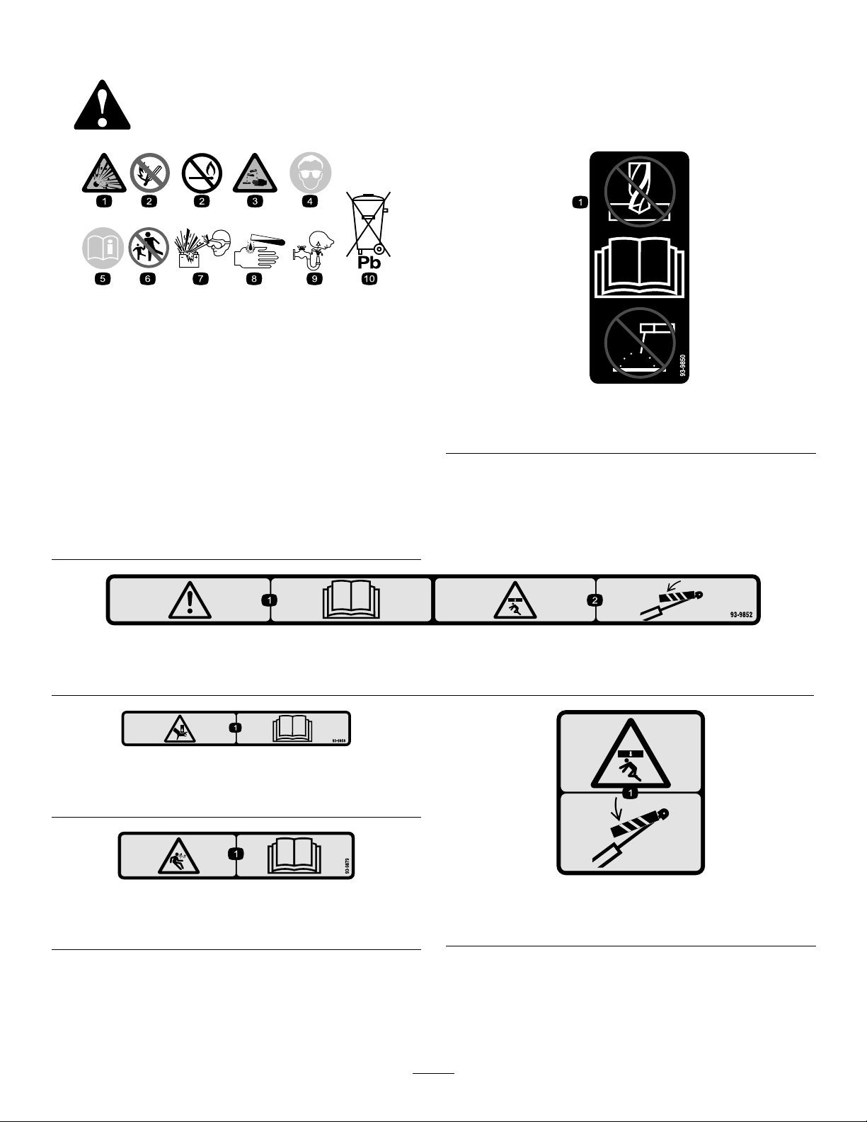
SafetyandInstructionalDecals
93-9899
Safetydecalsandinstructionsareeasilyvisibletotheoperatorandarelocatednearanyarea
ofpotentialdanger.Replaceanydecalthatisdamagedormissing.
BatterySymbols
Someorallofthesesymbolsareonyourbattery .
decalbatterysymbols
1.Explosionhazard6.Keepbystandersaway
fromthebattery .
2.Nore,opename,or
smoking
3.Causticliquid/chemical
burnhazard
7.Weareyeprotection;
explosivegasescan
causeblindnessandother
injuries.
8.Batteryacidcancause
blindnessorsevereburns.
93-9850
1.Donotrepairorrevise—readtheOperator'sManual.
4.Weareyeprotection.9.Flusheyesimmediately
withwaterandgetmedical
helpfast.
5.ReadtheOperator's
Manual.
10.Containslead;donot
discard
93-9852
1.Warning—readtheOperator’sManual.2.Crushinghazard—installthecylinderlock.
decal93-9868
93–9868
decal93-9850
decal93-9852
1.Crushinghazardofhand—readtheOperator’sManual.
93-9879
1.Storedenergyhazard—readtheOperator'sManual.
decal93-9879
decal93-9899
93-9899
1.Crushinghazard—installthecylinderlock.
5
Page 6
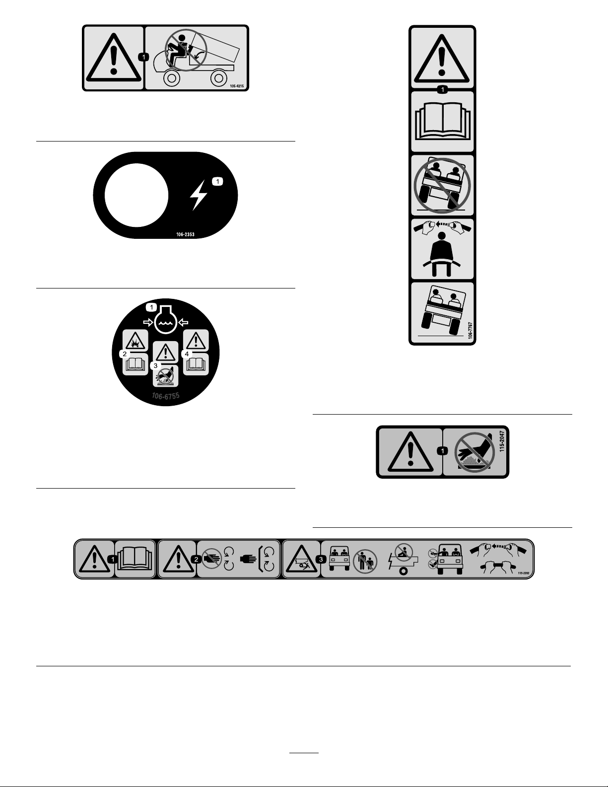
1.Warning—avoidpinchpoints.
1.Electricalpowerpoint
decal105-4215
105-4215
decal106-2353
106-2353
decal106-7767
106-7767
1.Warning—readtheOperator'sManual;avoidtippingthe
machine;weartheseatbelt;leanawayfromthedirection
themachineistipping.
decal106-6755
106-6755
1.Enginecoolantunder
pressure.
2.Explosionhazard—read
theOperator'sManual.
3.Warning—donottouchthe
hotsurface.
4.Warning—readthe
Operator'sManual.
115-2047
1.Warning—donottouchthehotsurface.
115-2282
1.Warning—readtheOperator'sManual.
2.Warning—stayawayfrommovingparts;keepallguardsandshieldsinplace.
3.Crushinghazard—keepbystandersoutoftheoperatingarea;donotcarrypassengersinthecargobed;keeparmsandlegs
insideofthevehicleatalltimes;useseatbeltsandhandholds.
decal115-2047
decal115-2282
6
Page 7
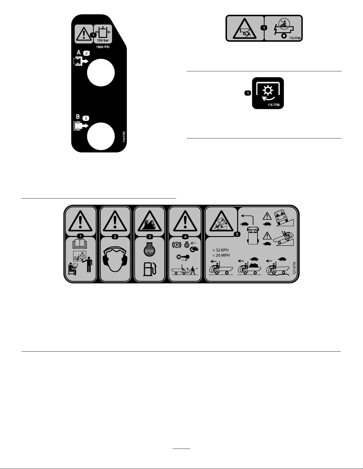
115-7723
1.Warning—thehydraulic-uidpressureis124bar(1,800psi).
2.CouplerA
3.CouplerB
decal115-7739
115-7739
1.Falling,crushinghazard—donotcarrypassengers.
decal115-7756
115-7756
1.High-owhydraulics—engaged
decal115-7723
121-9776
1.Warning—readtheOperator’sManualandreceiveproper
trainingbeforeoperatingthemachine.
2.Warning—wearhearingprotection.5.Tippinghazard—taketurnsslowly;driveslowlyupandacross
3.Firehazard—shutofftheenginebeforerefuelingthemachine.
4.Warning—engagetheparkingbrake,shutofftheengine,and
removethekeyfromthekeyswitchbeforewalkingawayfrom
themachine.
cliffs;withnoload,donotexceed32kph(20mph);while
carryingaloadorwhendrivingonuneventerrain,driveslowly.
7
decal121-9776
Page 8
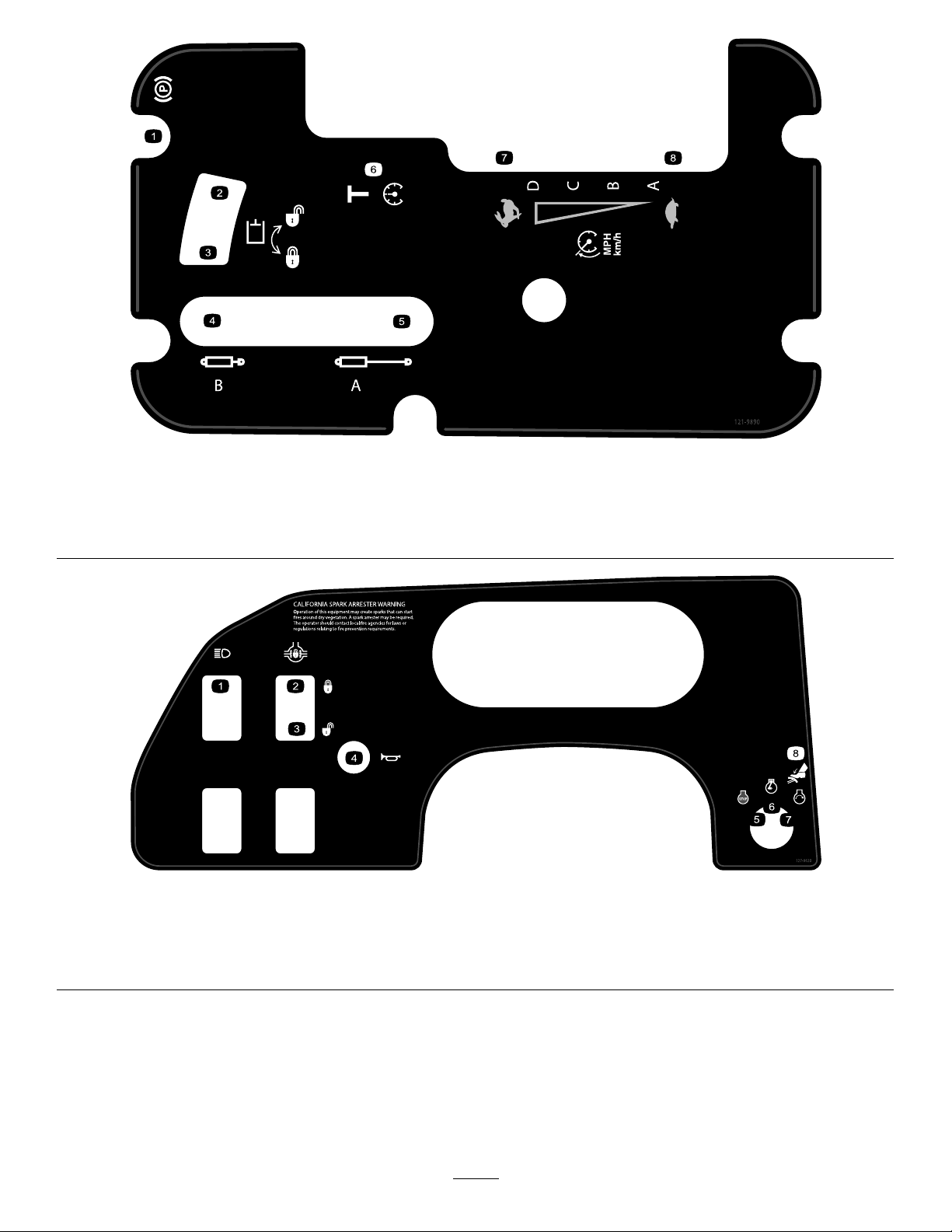
decal121-9890
121-9890
1.Parkingbrake
2.Hydraulicsystem—unlock
4.Cylinderretract
5.Cylinderextend
3.Hydraulicsystem—lock6.Transport
127-8620
1.Headlights4.Horn7.Engine—start
2.Differentiallock—lock5.Engine—shutoff
3.Differentiallock—unlock
6.Engine—run
7.Fast
8.Slow
decal127-8620
8.Brake
8
Page 9
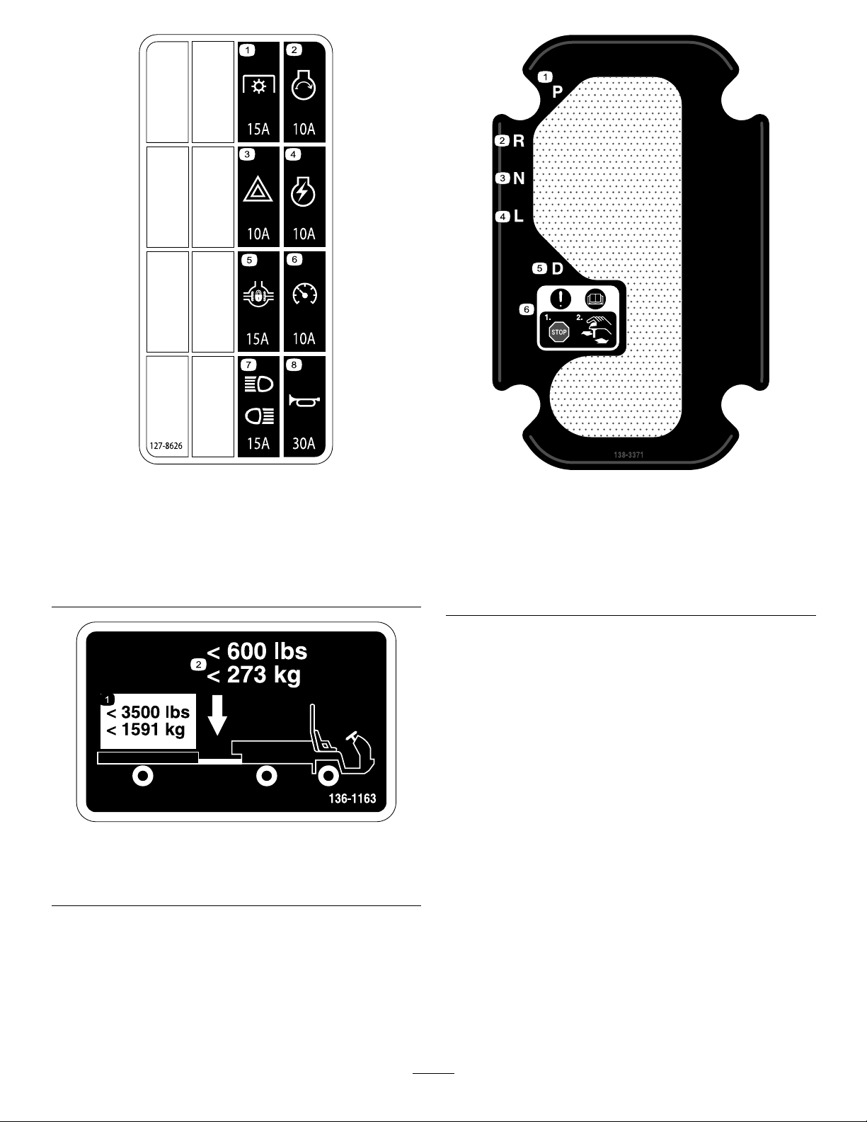
127-8626
1.Powertakeoff(15A)5.Differentiallock(15A)
2.Startengine(10A)6.Speedometer(10A)
3.Hazardlights(10A)
7.Headlightsandrearlights
(15A)
4.Engineignition(10A)8.Horn(30A)
136-1163
decal127-8626a
decal136-1163
decal138-3371
138-3371
1.Park4.Low
2.Reverse5.Drive
3.Neutral6.Attention—readthe
Operator’sManual;stop
themachinebefore
changinggears.
1.Donotexceedatransport
loadof1591kg(3,500lb).
2.Donotexceedatongue
weightof273kg(600lb).
9
Page 10
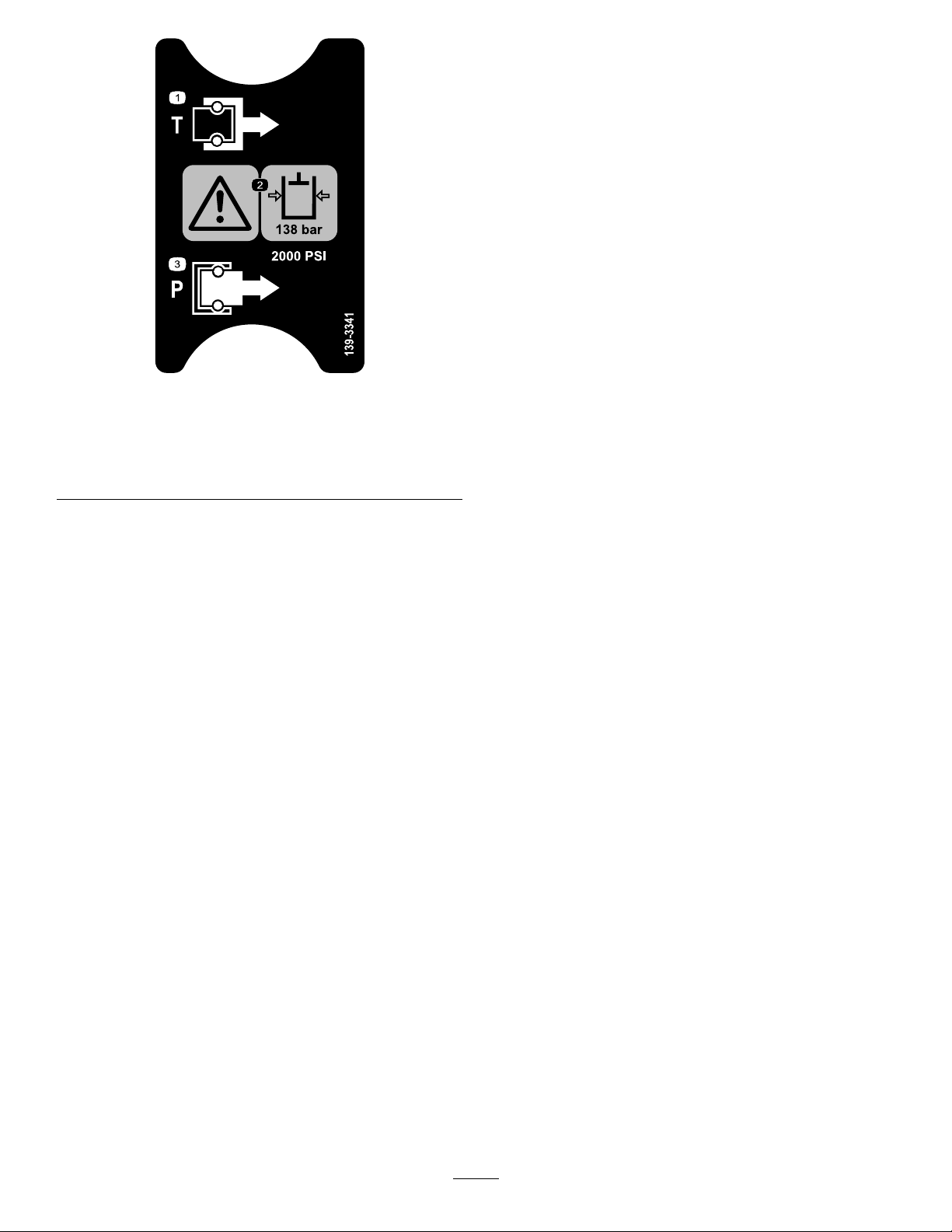
1.Tank3.Pressure
2.Warning—the
hydraulic-uidpressureis
138bar(2,000psi).
decal139-3341
139-3341
10
Page 11
Setup
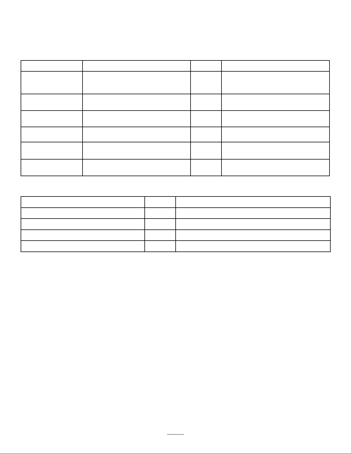
LooseParts
Usethechartbelowtoverifythatallpartshavebeenshipped.
ProcedureDescription
1
2
3
4
5
6
MediaandAdditionalParts
Description
Operator'sManual
OperatorTrainingMaterial
Steeringwheel
Cover
Washer(5/8inch)
Nopartsrequired
Nopartsrequired
Rollbar1
Flange-headbolt(1/2x1-1/4inches)
Nopartsrequired
Nopartsrequired
Qty.
1
1
Readbeforeoperatingthemachine.
Viewbeforeoperatingthemachine.
Qty.
Use
1
1
1
–
–
6
–
–
Installthesteeringwheel(TCmodels
only).
Connectthebattery(TCmodelsonly).
Checktheuidlevelsandtirepressure.
Installtherollbar.
Connectthecontinuously-variable
transmissionintakeduct.
Burnishthebrakes.
Use
CVTKit121-9853
CVTAdapter127-8750
1
1
ConnecttheCVTIntakeDuct(TCModelsOnly)
ConnecttheCVTIntakeDuct(TCModelsOnly)
Note:Determinetheleftandrightsideofthemachinefromthenormaloperatingposition.
11
Page 12
1
2
InstallingtheSteering
Wheel
TCModelsOnly
Partsneededforthisprocedure:
1
Steeringwheel
1
Cover
1
Washer(5/8inch)
Procedure
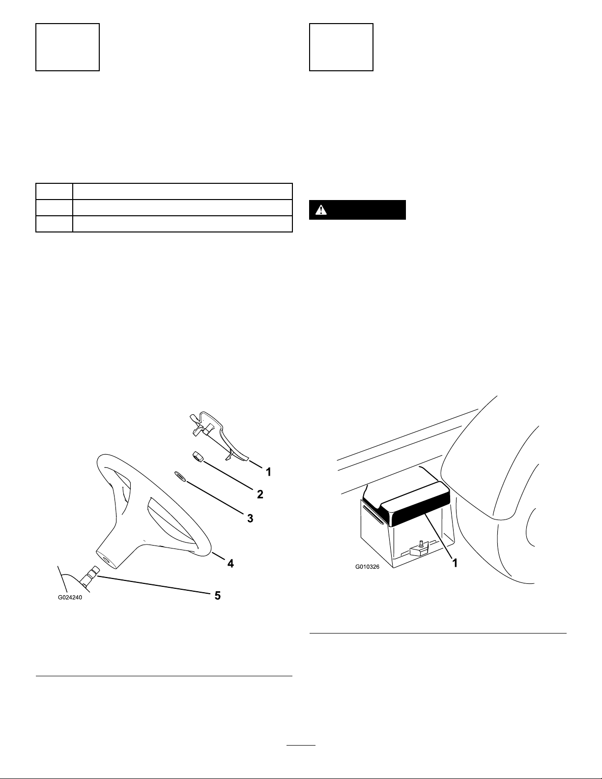
1.Ifthecoverisinstalled,removeitfromthehub
ofthesteeringwheel(Figure3).
2.Removethenutfromthesteeringshaft(Figure
3).
3.Slidethesteeringwheelandwasherontothe
steeringshaft(Figure3).
4.Securethesteeringwheeltotheshaftwiththe
nutandtightenitto27to34N∙m(20to25ft-lb).
5.Installthecoveronthesteeringwheel(Figure3).
ConnectingtheBattery
TCModelsOnly
NoPartsRequired
Procedure
WARNING
Incorrectlyroutingthebatterycablecould
damagethemachineandcables,causing
sparks.Sparkscancausethebatterygasses
toexplode,resultinginpersonalinjury.
•Alwaysdisconnectthenegativebattery
cable(black)beforedisconnectingthe
positivebatterycable(red).
•Alwaysconnectthepositivebatterycable
(red)rst.
1.Squeezethebatterycovertoreleasethetabs
fromthebatterybase(Figure4).
Figure3
1.Cover4.Steeringwheel
2.Nut
3.Washer(5/8inch)
5.Steeringshaft
g010326
g024240
1.Batterycover
2.Removethebatterycoverfromthebatterybase
(Figure4).
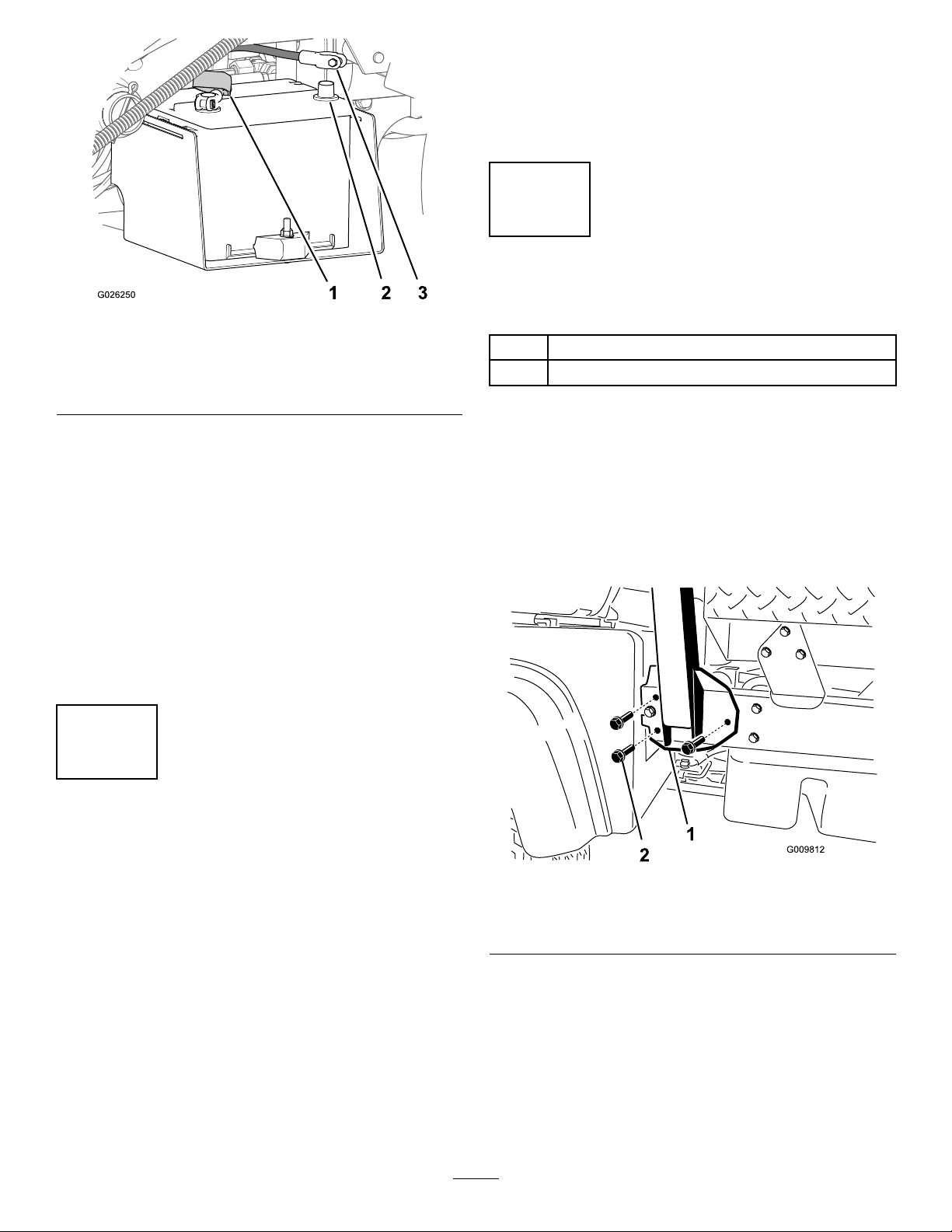
3.Connectthepositivebatterycable(red)tothe
positive(+)terminalofthebatteryandsecure
thecablewiththeboltsandnuts(Figure5).
12
Figure4
Page 13
4.Checkthebrake-uidlevelbeforeyourststart
theengine;refertoCheckingtheBrake-Fluid
Level(page56).
5.Checktheairpressureinthetires;referto
CheckingtheTirePressure(page21).
4
InstallingtheRollBar
Figure5
1.Insulatorboot(positive
batterycable)
2.Negativebatterypost
4.Slidetheinsulatorbootoverthepositive
terminal.
Note:Theinsulatorbootpreventsapossible
short-to-groundfromoccurring.
5.Connectthenegativebatterycable(black)tothe
negative(–)terminalofthebatteryandsecure
thecablewithboltsandnuts.
6.Alignthebatterycovertothebatterybase
(Figure4).
7.Squeezethebatterycover,alignthetabsto
thebatterybase,andreleasethebatterycover
(Figure4).
3.Negativebatterycable
(black)
g026250
Partsneededforthisprocedure:
1Rollbar
6
Flange-headbolt(1/2x1-1/4inches)
Procedure
1.Applymedium-grade(service-removable)
thread-lockingcompoundtothethreadsofthe6
ange-headbolts(1/2x1-1/4inches).
2.Aligneachsideoftherollbarwiththemounting
holesoneachsideofthemachineframe(Figure
6).
3
CheckingtheFluidLevels
andTirePressure
NoPartsRequired
Procedure
1.Checktheengine-oillevelbeforeandafter
yourststarttheengine;refertoCheckingthe
Engine-OilLevel(page41).
2.Checkthetransmission-uidlevelbeforeyou
rststarttheengine;refertoCheckingthe
Transmission-FluidLevel(page49).
3.Checktheengine-coolantlevelbeforeyou
rststarttheengine;refertoCheckingthe
Engine-CoolantLevel(page53).
Figure6
1.Rollbarmountingbracket
3.Securetherollbarmountingbrackettothe
machineframeusing3ange-headbolts(1/2x
1-1/4inches)oneachside(Figure6).
4.Torquetheange-headbolts(1/2x1-1/4inches)
to115N∙m(85ft-lb).
13
2.Flange-headbolt(1/2x
1-1/4inches)
g009812
Page 14
5
ConnectingtheCVT-Intake
Duct
NoPartsRequired
Procedure
4.Removethebedsupport,lowerthebed,shutoff
theengine,andremovethekey.
6
BurnishingtheBrakes
NoPartsRequired
Important:Removetheplasticbagcoveringthe
endoftheCVTductbeforestartingtheengine.
TheCVTKit(PartNo.121-9853)andAdapterKit
(PartNo.127-8750)arerequiredforthisprocedure.
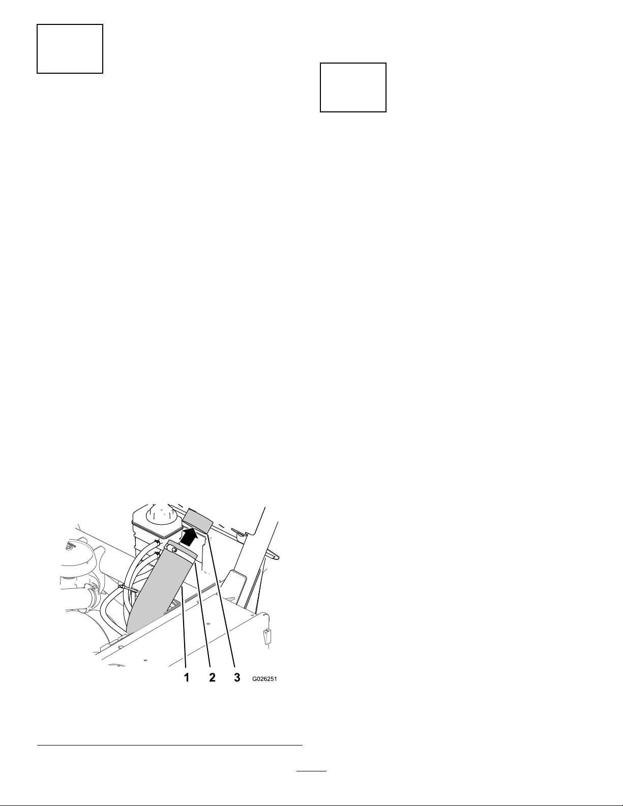
1.Loosenthehoseclampsecuringtheplasticbag
attheendoftheCVT-intakehoseandremove
thebag.
2.Raisethecargobedbyperformingthefollowing:
A.Engagetheparkingbrake.
B.Starttheengine.
C.Movethehydraulic-liftleverrearwardto
raisethecargobox.
D.Shutofftheengine.
E.Removethebedsupportfromthestorage
bracketsonthebackoftheROPSpanel
andinstallthesupportontothecylinderrod
ofthebed-liftcylinder;refertoUsingthe
BedSupport(page35).
3.AligntheCVT-intakehoseontotheintake-tube
connectoratthebacksideoftheROPSpanel
andtightenthehoseclamp(Figure7).
Procedure
Toensureoptimumperformanceofthebrakesystem,
burnishthebrakesbeforeuse.
1.Bringthemachineuptofullspeed,applythe
brakestorapidlystopthemachinewithout
lockingupthetires.
2.Repeatthisprocedure10times,waiting1minute
betweenstops,toavoidoverheatingthebrakes.
Important:Thisprocedureismosteffective
ifthemachineisloadedwith454kg(1,000
lb).
1.CVT-intakehose
2.Hoseclamp
g026251
Figure7
3.Intake-tubeconnector
14
Page 15
ProductOverview
Controls
Becomefamiliarwithallthecontrolsbeforeyoustart
theengineandoperatethemachine.
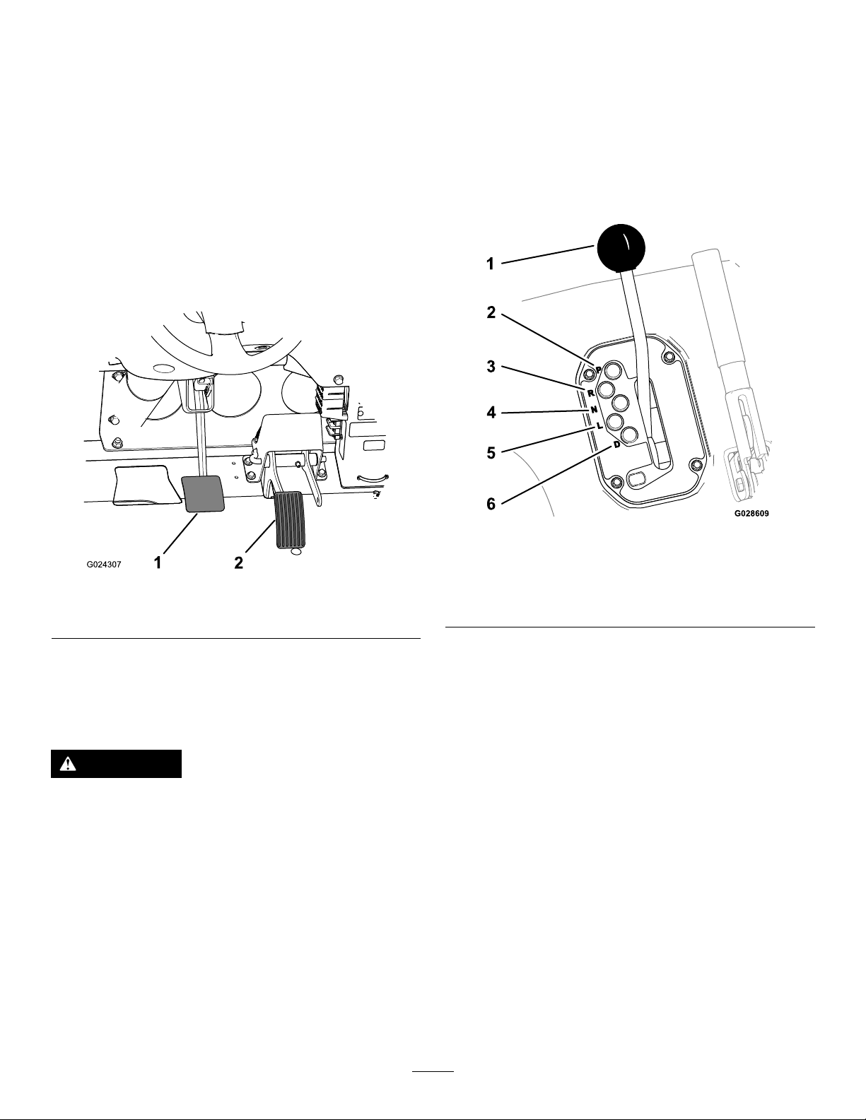
AcceleratorPedal
Usetheacceleratorpedal(Figure8)tovarytheground
speedofthemachinewhenthetransmissionisin
gear.Pressingdowntheacceleratorpedalincreases
theenginespeedandgroundspeed.Releasingthe
pedaldecreasestheenginespeedandgroundspeed.
TransmissionLever
Usethetransmissionlever(Figure9)toshiftthe
transmissionbetweenP(PARK),R(REVERSE),N
(NEUTRAL),L(LOWFORWARD),andD(DRIVE)ground
operation.
Important:Donotshiftthetransmissiontothe
REVERSE,LOW,orDRIVEgearunlessthemachine
ismotionlessandtheengineisatlowidle;
otherwise,youcoulddamagethetransmission.
Figure8
1.Brakepedal2.Acceleratorpedal
BrakePedal
Usethebrakepedaltostoporslowthemachine
(Figure8).
CAUTION
Operatingamachinewithwornorincorrectly
adjustedbrakescanmayresultinpersonal
injury.
Ifthebrakepedaltravelstowithin25mm(1
inch)ofthemachineoorboard,adjustor
repairthebrakes.
g028609
Figure9
g024307
1.Transmissionlever
2.P(park)5.L(lowforward)
3.R(reverse)6.D(drive)
4.N(neutral)
15
Page 16
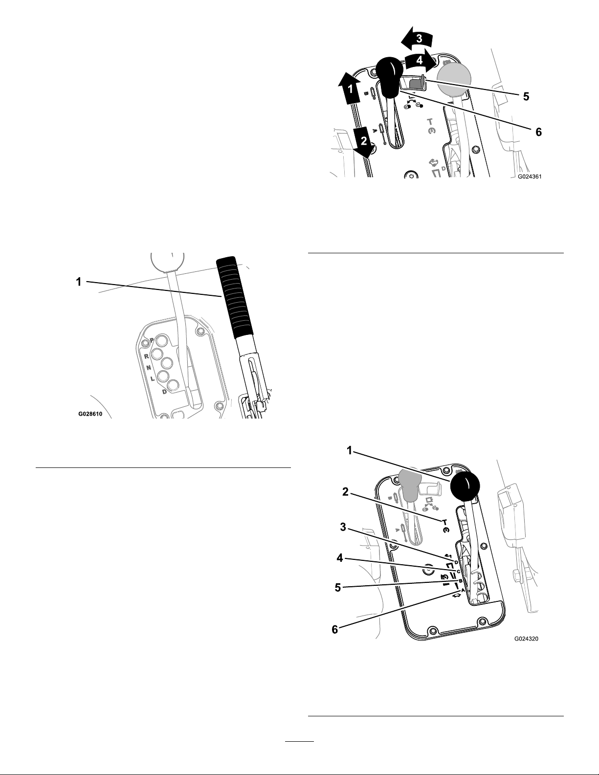
Parking-BrakeLever
Wheneveryoushutofftheengine,engagethe
parkingbrake(Figure10)topreventthemachinefrom
accidentallymoving.Ifthemachineisparkedona
steepgrade,ensurethatyouengagetheparking
brake.
•Toengagetheparkingbrake,pullbackonthe
parking-brakelever.
•Todisengagetheparkingbrake,pushthe
parking-brakeleverforward.
Note:Disengagetheparkingbrakebefore
movingthemachine.
•Ifyouparkthemachineonasteepuphillor
downhillgrade,shiftthetransmissionintoP(PARK)
andengagetheparkingbrake.Placechocksat
thedownhillsideofthewheels.
Figure10
1.Parking-brakelever
g024361
Figure11
1.Lowerthebed4.Unlocked
2.Raisethebed
3.Locked
5.Hydraulic-liftlock
6.Hydraulic-liftlever
Hydraulic-LiftLock
Thehydraulic-liftlocksecurestheliftlever,sothatthe
hydrauliccylindersdonotoperatewhenthemachine
isnotequippedwithabed(Figure11).Italsolocksthe
liftleverintheONpositionwhenusingthehydraulics
forattachments.
Speed-RangeLever
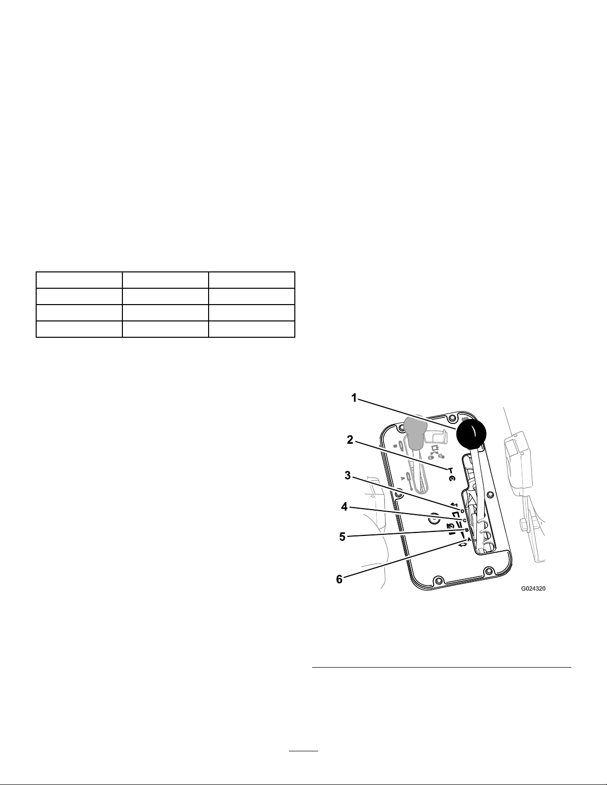
Usethespeed-rangelever(Figure12)toselect1of
the4work-speedrangesforprecisecontrolofthe
g028610
maximumgroundspeedoratransportspeedrange
formovingthemachinebetweenjobsites.
Hydraulic-LiftLever
Thehydraulicliftraisesandlowersthebed.Move
thehydraulic-liftleverrearwardtoraisethebed,and
forwardtolowerit(Figure1 1).
Important:Whenloweringthebed,holdthelever
intheforwardpositionfor1to2secondsafterthe
bedcontactstheframetosecureitinthelowered
position.Donotholdthehydraulicliftintheraise
orlowerpositionformorethan5seconds,once
thecylindersreachtheendoftheirtravel.
g024320
Figure12
1.Speed-rangelever4.C(mid-highrange)
2.T(transportrange)5.B(mid-lowrange)
3.D(highrange)6.A(lowrange)
16
Page 17
ControlPanel
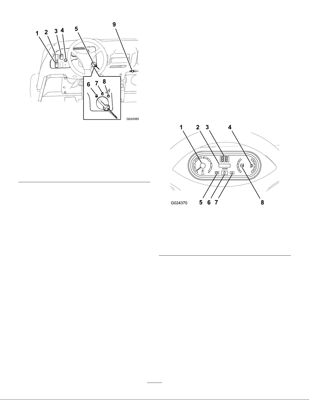
KeySwitch
Usethekeyswitch(Figure13)tostartandshutoffthe
engine.T oshutofftheengine,rotatethekeyswitch
counterclockwisetotheOFFposition.
Thekeyswitchhas3positions:OFF,RUN,and
START.RotatethekeyswitchclockwisetotheSTART
positiontoengagethestartermotor.Releasethekey
switchwhentheenginestarts.Thekeyswitchmoves
automaticallytotheONposition.
PowerPoint
Usethepowerpoint(Figure13)topoweroptional12
Velectricalaccessories.
Figure13
1.High-owhydraulics
switch(TCmodelsonly)
2.Lightswitch
3.Differentialswitch8.Start
4.Hornbutton(TCmodels
only)
5.Keyswitch
High-FlowHydraulicsSwitch
6.Off
7.On
9.Powerpoint
TCModelsOnly
Pushtheswitchdowntostartthehigh-owhydraulics
andpushtheswitchuptoshutoffthehydraulics
(Figure13).
Note:Y oumustsetthehigh-owhydraulicsswitchto
theOFFpositiontostarttheengine.
LightSwitch
Pushthelightswitch(Figure13)totogglethe
headlightsonoroff.
Differential-LockSwitch
g024365
InstrumentCluster
1.Tachometer
2.Hourmeter
3.Speedometer
4.Fuelgauge
Tachometer
g024370
Figure14
5.Charge-indicatorlight
6.Check-enginelight
7.Low-oilpressurelight
8.Coolant-temperature
gauge
Thetachometerdisplaysthespeedoftheengine
(Figure14).
Thedifferential-lockswitchallowsyoutolocktherear
axleforincreasedtraction.Pushthedifferential-lock
switch(Figure13)totogglethedifferentiallockonor
off.
Note:Y oumaylockandunlockthedifferentialwhile
themachineisinmotion.
HornButton
InternationalModelsOnly
Thehornbuttonislocatedonthecontrolpanel(Figure
13).Pressthehornbuttontosoundthehorn.
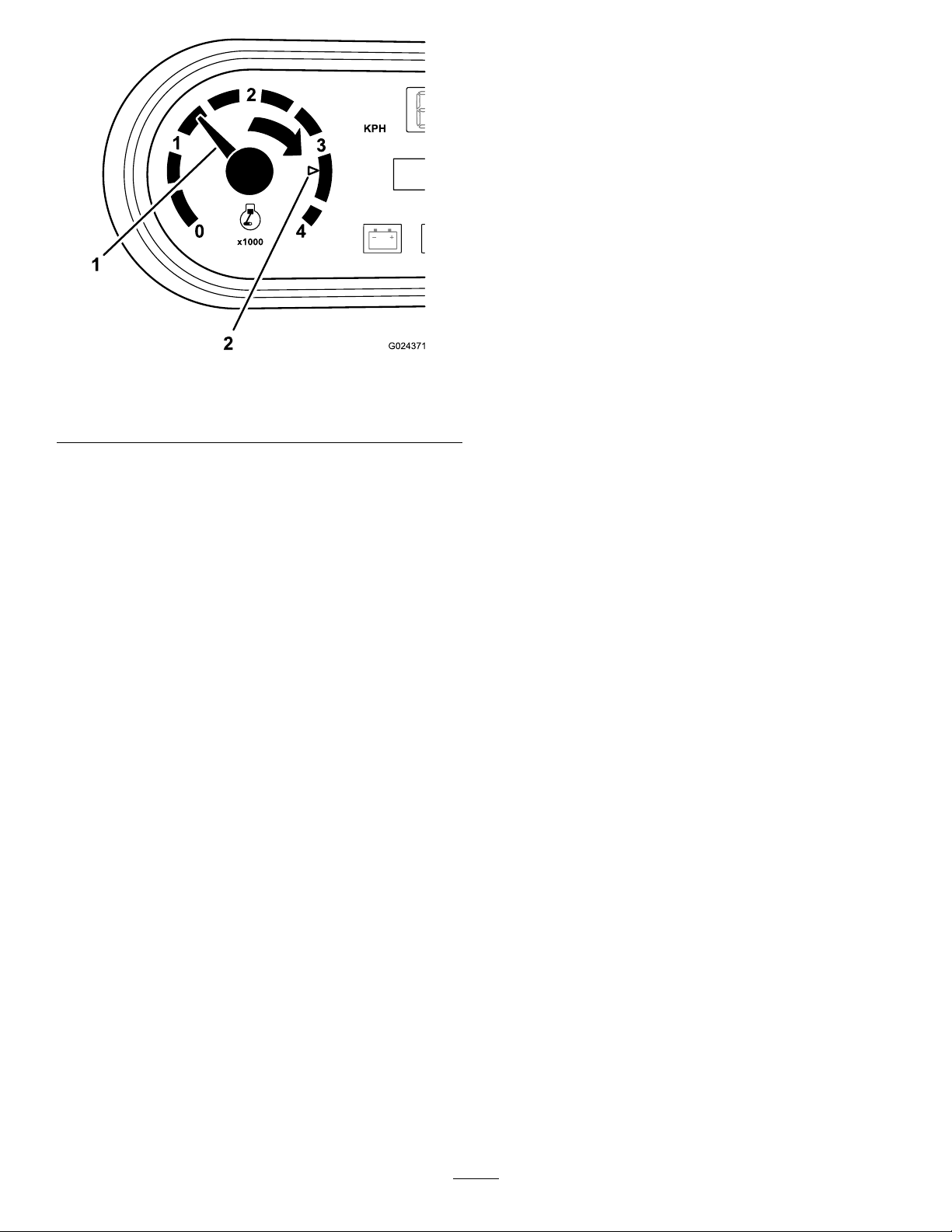
Note:Thewhitetriangleindicatesthedesiredengine
speedfor540rpmPTOoperation.
17
Page 18
Note:Theoil-pressurelightshouldglowred.
Ifthelightdoesnotfunction,eitherabulbis
burnedoutorthereisamalfunctioninthe
systemthatyoumustrepair.
Note:Ifenginewasjustshutoff,itmaytake1
to2minutesforthelighttocomeon.
Coolant-TemperatureGaugeandLight
Thecoolant-temperaturegaugeandlightregistersthe
coolanttemperatureintheengineandoperatesonly
whenthekeyswitchisinONposition(Figure14).The
indicatorlightblinksrediftheengineoverheats.
FuelGauge
Figure15
1.Enginespeed(rpm)2.3,300rpmfor540rpm
PTOoperation
HourMeter
Thehourmeterindicatesthetotalhoursofmachine
operation.Thehourmeter(Figure14)startsto
functionwheneveryourotatethekeyswitchtotheON
positionoriftheengineisrunning.
Speedometer
Thespeedometerregistersthegroundspeedofthe
machine(Figure14).Thespeedometerisinmph,but
youcaneasilyconvertittokm/h;refertoConverting
theSpeedometer(page58).
Check-EngineLight
Thecheck-enginelight(Figure14)illuminatestonotify
theoperatorofanenginemalfunction.
ContactyourauthorizedTorodistributor.
g024371
Thefuelgaugeshowstheamountoffuelinthetank.
ItdisplaysonlywhenkeyswitchisintheONposition
(Figure14).Theredsegmentofthedisplayindicates
alow-fuellevelandtheashingredlightindicatesthat
thefuelinthetankisnearempty.
Oil-Pressure-WarningLight
Theoil-pressure-warninglight(Figure14)illuminates
iftheengine-oilpressuredropsbelowasafelevel
whiletheengineisrunning.
Important:Ifthelightickersorremainson,
stopthemachine,shutofftheengine,andcheck
theoillevel.Iftheoillevelislow,butadding
oildoesnotcausethelighttogooutwhenthe
engineisstarted,shutofftheengineimmediately,
andcontactyourAuthorizedServiceDealerfor
assistance.
Checktheoperationofthewarninglightsasfollows:
1.Engagetheparkingbrake.
2.TurnthekeyswitchtotheON/PREHEATposition,
butdonotstarttheengine.
18
Page 19
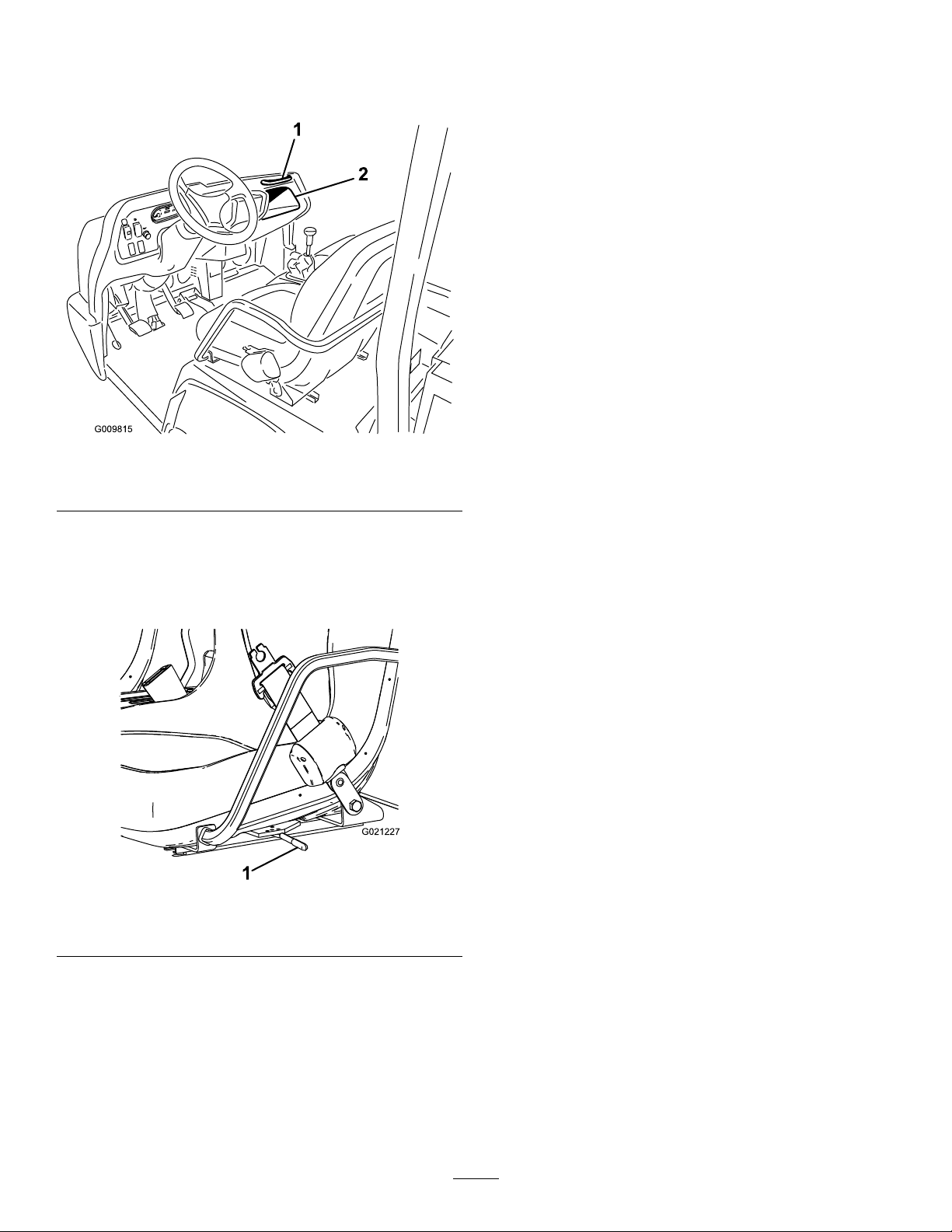
PassengerHandhold
Thepassengerhandholdislocatedonthedashboard
(Figure16).
Figure16
g009815
1.Passengerhandhold
2.Storagecompartment
Seat-AdjustmentLever
Youcanadjusttheseatforwardandrearwardforyour
comfort(Figure17).
Figure17
1.Seat-adjustmentlever
g021227
19
Page 20

Specications
Note:Specicationsanddesignaresubjectto
changewithoutnotice.
Overallwidth165.1cm(65inches)
Withoutbed:326cm(128inches)
Withfullbed:331cm(130inches) Overalllength
With2/3bedinrear-mountinglocation:346cm(136inches)
Baseweight(dry)
Ratedcapacity(includes91kg(200lb)operator,
91kg(200lb)passenger,andloadedattachment)
Maximumgrossvehicleweight(GVW)2363kg(5,210lb)
Towcapacity
Groundclearance18cm(7inches)withnoload
Wheelbase
Model07390:866kg(1,905lb)
Model07390TC:887kg(1,951lb)
Model07390:1498kg(3,295lb)
Model07390TC:1477kg(3,249lb)
Tongueweight:272kg(600lb)
Maximumtrailerweight:1587kg(3,500lb)
118cm(70inches)
Wheeltread(centerlinetocenterline)
Height
Front:117cm(46inches)
Rear:121cm(48inches)
192.5cm(75-13/16inches)totopofROPS
Attachments/Accessories
AselectionofToroapprovedattachmentsandaccessoriesisavailableforusewiththemachinetoenhance
andexpanditscapabilities.ContactyourAuthorizedServiceDealerorauthorizedT orodistributororgoto
www.T oro.comforalistofallapprovedattachmentsandaccessories.
Toensureoptimumperformanceandcontinuedsafetycerticationofthemachine,useonlygenuineT oro
replacementpartsandaccessories.Replacementpartsandaccessoriesmadebyothermanufacturerscouldbe
dangerous,andsuchusecouldvoidtheproductwarranty .
20
Page 21
Operation
PerformingDaily
Maintenance
BeforeOperation
BeforeOperationSafety
GeneralSafety
•Neverallowchildrenorpeoplewhoarenottrained
orphysicallycapabletosafelyoperateorservice
themachine.Localregulationsmayrestrictthe
ageoftheoperator.Theownerisresponsiblefor
trainingalloperatorsandmechanics.
•Becomefamiliarwiththesafeoperationofthe
equipment,operatorcontrols,andsafetysigns.
•Shutofftheengine,removethekey(ifequipped),
andwaitforallmovementtostopbeforeyouleave
theoperator’sposition.Allowthemachinetocool
beforeadjusting,servicing,cleaning,orstoringit.
•Knowhowtostopandshutoffthemachinequickly.
•Ensurethattherearenotmoreoccupants(youand
yourpassenger(s))thanthenumberofhandholds
equippedonthemachine.
ServiceInterval:Beforeeachuseordaily
Beforestartingthemachineeachday ,performthe
EachUse/DailyprocedureslistedinMaintenance
(page32).
CheckingtheTirePressure
ServiceInterval:Beforeeachuseordaily
Fronttiresairpressurespecication:220kPa(32
psi)
Teartiresairpressurespecication:124kPa(18
psi)
Important:Checkthetirepressurefrequently
toensureproperination.Ifthetiresarenot
inatedtothecorrectpressure,thetireswillwear
prematurelyandmaycausethe4-wheeldriveto
bind.
Figure18showsanexampleoftirewearcausedby
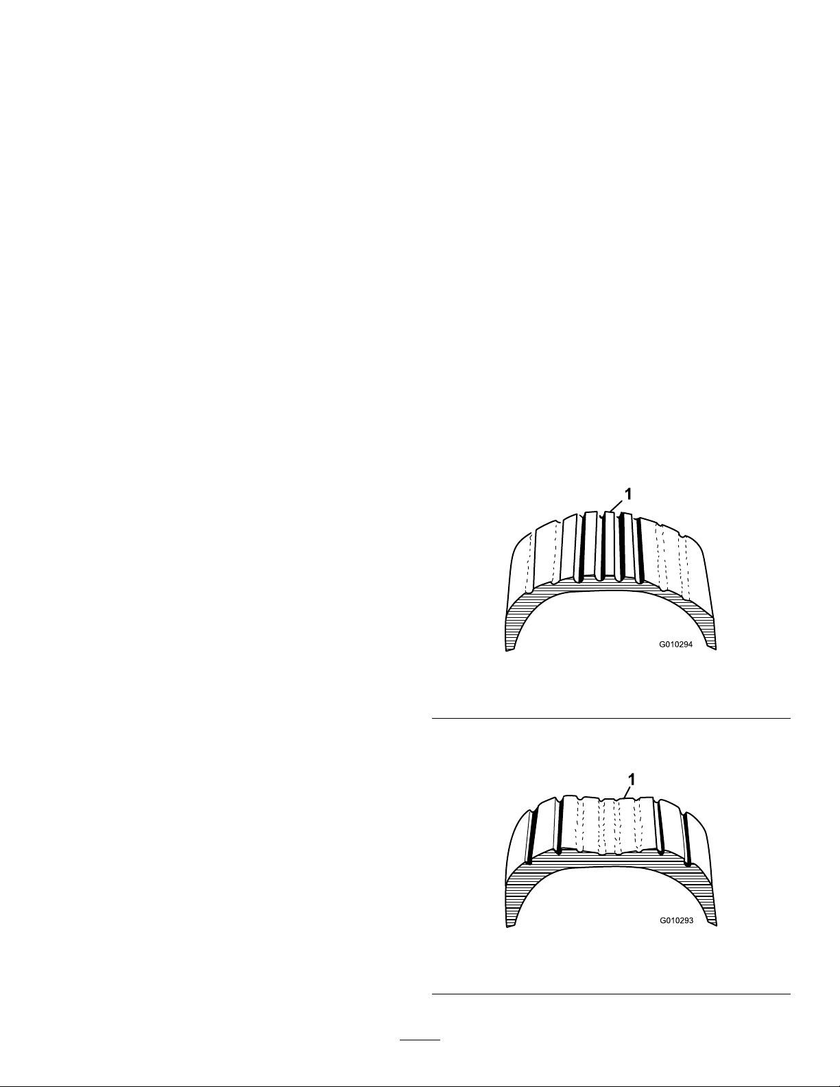
under-ination.
•Checkthatallsafetydevicesanddecalsarein
place.Repairorreplaceallsafetydevicesand
replaceallillegibleormissingdecals.Donot
operatethemachineunlesstheyarepresentand
functioningproperly.
FuelSafety
•Useextremecareinhandlingfuel.Itisammable
anditsvaporsareexplosive.
•Extinguishallcigarettes,cigars,pipes,andother
sourcesofignition.
•Useonlyanapprovedfuelcontainer.
•Donotremovethefuelcaporllthefueltank
whiletheengineisrunningorhot.
•Donotaddordrainfuelinanenclosedspace.
•Donotstorethemachineorfuelcontainerwhere
thereisanopename,spark,orpilotlight,such
asonawaterheaterorotherappliance.
•Ifyouspillfuel,donotattempttostarttheengine;
avoidcreatinganysourceofignitionuntilthefuel
vaporshavedissipated.
g010294
Figure18
1.Under-inatedtire
Figure19showsanexampleoftirewearcausedby
over-ination.
g010293
Figure19
1.Over-inatedtire
21
Page 22
AddingFuel
•Forbestresults,useonlyclean,fresh(lessthan
30daysold),unleadedgasolinewithancetane
ratingof87orhigher((R+M)/2ratingmethod).
•Ethanol:Gasolinewithupto10%ethanol
(gasohol)or15%MTBE(methyltertiarybutyl
ether)byvolumeisacceptable.Ethanoland
MTBEarenotthesame.Gasolinewith15%
ethanol(E15)byvolumeisnotapprovedforuse.
Neverusegasolinethatcontainsmorethan
10%ethanolbyvolume,suchasE15(contains
15%ethanol),E20(contains20%ethanol),orE85
(containsupto85%ethanol).Usingunapproved
gasolinemaycauseperformanceproblemsand/or
enginedamagewhichmaynotbecoveredunder
warranty.
•Donotusegasolinecontainingmethanol.
•Donotstorefueleitherinthefueltankorfuel
containersoverthewinterunlessyouuseafuel
stabilizer.
•Donotaddoiltogasoline.
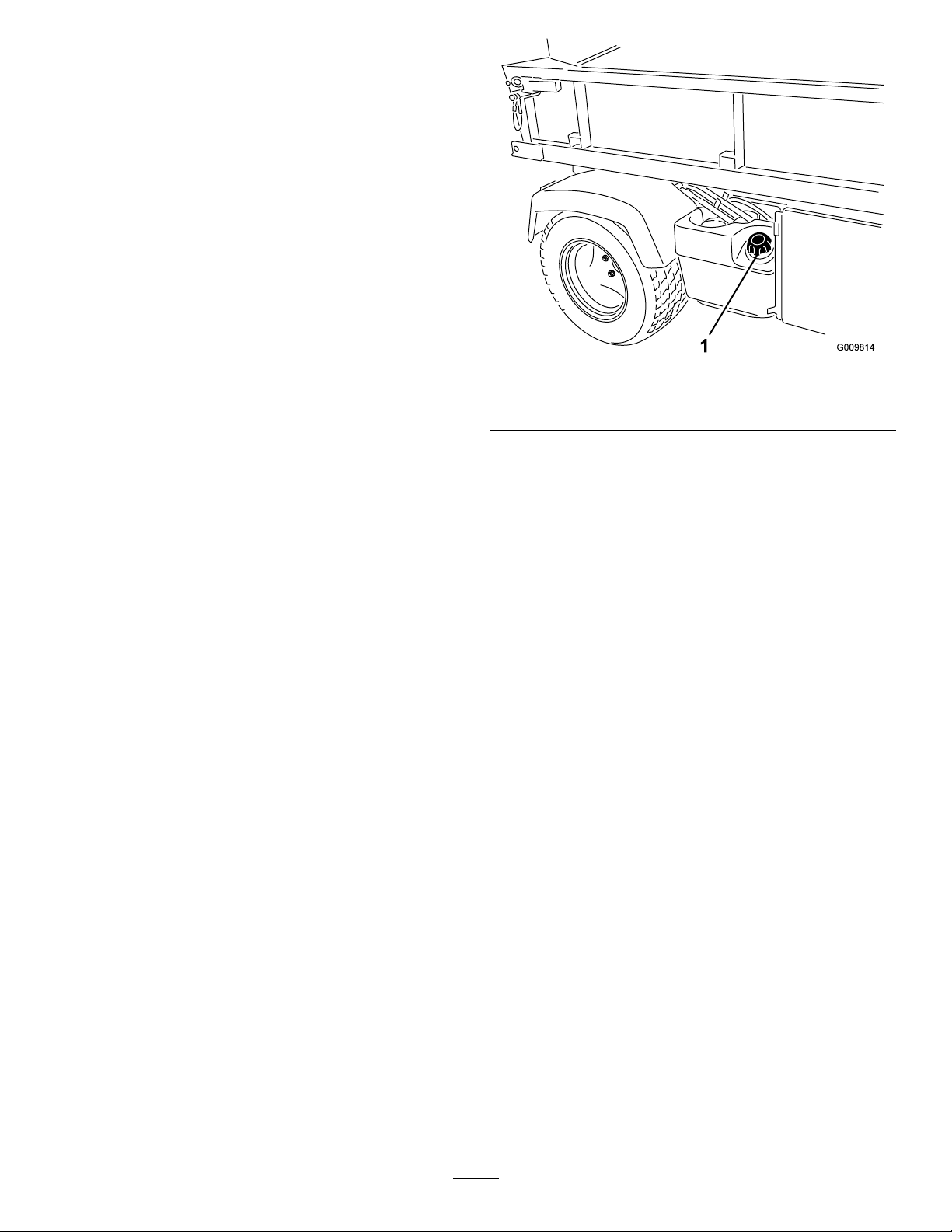
g009814
Figure20
1.Fuel-tankcap
3.Fillthetanktoapproximately25mm(1inch)
belowthebottomofthellerneck,andinstall
thecap.
UsingStabilizer/Conditioner
Usefuelstabilizer/conditionerinthemachinetokeep
thefuelfreshlongerwhenusedasdirectedbythe
fuel-stabilizermanufacturer.
Important:Donotusefueladditivescontaining
methanolorethanol.
Addtheamountoffuelstabilizer/conditionertofresh
fuelasdirectedbythefuel-stabilizermanufacturer.
FillingtheFuelTank
Fuel-tankcapacity:25L(6.5USgallons).
1.Cleantheareaaroundthefuel-tankcap.
2.Removethefuel-tankcap(Figure20).
Note:Donotoverllthefueltank.
4.Wipeupanyspilledfueltopreventarehazard.
BreakinginaNewMachine
ServiceInterval:Aftertherst100hours—Perform
theguidelinesforbreakinginanew
machine.
Performthefollowingtoprovideproperperformance
forthemachine:
•Ensurethatthebrakesareburnished;referto6
BurnishingtheBrakes(page14).
•Checktheuidandengine-oillevelsregularly.
Remainalertforsignsthatthemachineorits
componentsareoverheating.
•Afterstartingacoldengine,letitwarmupforabout
15secondsbeforeusingthemachine.
Note:Allowmoretimefortheenginetowarmup
whenoperatingincoldtemperatures.
•Varythemachinespeedduringoperation.Avoid
faststartsandquickstops.
•Abreak-inoilfortheengineisnotrequired.
Originalengineoilisthesametypespeciedfor
regularoilchanges.
•RefertoMaintenance(page32)foranyspecial,
low-hourchecks.
22
Page 23

Checkingthe
Safety-InterlockSystem
ServiceInterval:Beforeeachuseordaily
VerifyingtheBrakePedal
Safety-InterlockSwitch
1.Sitontheoperator’sseatandengagethe
parkingbrake.
Thepurposeofthesafety-interlocksystemisto
preventtheenginefromcrankingorstarting,unless
youpressthebrakepedalandhavethehydraulic-lift
leverintheNEUTRALposition.
CAUTION
Ifthesafety-interlockswitchesare
disconnectedordamaged,themachinecould
operateunexpectedly,causingpersonal
injury.
•Donottamperwiththesafety-interlock
switches.
•Checktheoperationofthesafety-interlock
switchesdaily,andreplaceanydamaged
switchesbeforeoperatingthemachine.
Note:RefertotheattachmentOperator’sManual
forproceduresoncheckingtheattachmentinterlock
system.
VerifyingtheHydraulic-LiftLever
Safety-InterlockSwitch
1.Sitontheoperator’sseatandengagethe
parkingbrake.
2.MovetheshiftlevertotheNEUTRALposition
andensurethatthehydraulic-liftleverisinthe
centerposition.
3.Ifyouhaveanon-TCmodelwiththeHigh-Flow
HydraulicKit(optional)orTCmodel,setthe
high-owhydraulicswitchtotheOFFposition.
4.Pressthebrakepedal.
5.Movethehydraulic-liftleverforwardandrotate
thekeyswitchclockwisetotheST ARTposition.
2.MovetheshiftlevertotheNEUTRALposition
andensurethatthehydraulic-liftleverisinthe
centerposition.
3.Ifyouhaveanon-TCmodelwiththeHigh-Flow
HydraulicKit(optional)orTCmodel,setthe
high-owhydraulicswitchtotheOFFposition.
4.RotatethekeyswitchclockwisetotheSTART
position.
Note:Donotpressthebrakepedal.
Note:Iftheenginecranksorstarts,thereis
amalfunctionintheinterlocksystemthatyou
mustrepairbeforeoperatingthemachine.
VerifyingtheHigh-FlowHydraulic
Safety-InterlockSwitch
Note:Thisprocedureisforanon-TCmodelwiththe
High-FlowHydraulicKit(optional)oraTCmodel
1.Sitontheoperator’sseatandengagethe
parkingbrake.
2.MovetheshiftlevertotheNEUTRALposition
andensurethatthehydraulic-liftleverisinthe
centerposition.
3.Setthehigh-owhydraulicswitchtotheON
position.
4.Pressthebrakepedal.
5.RotatethekeyswitchclockwisetotheSTART
position.
Note:Iftheenginecranksorstarts,thereis
amalfunctionintheinterlocksystemthatyou
mustrepairbeforeoperatingthemachine.
Note:Iftheenginecranksorstarts,thereis
amalfunctionintheinterlocksystemthatyou
mustrepairbeforeoperatingthemachine.
23
Page 24

DuringOperation
DuringOperationSafety
GeneralSafety
•Theowner/operatorcanpreventandisresponsible
foraccidentsthatmaycausepersonalinjuryor
propertydamage.
•Passengersshouldsitinthedesignatedseating
positionsonly.Donotcarrypassengersinthe
cargobed.Keepbystandersandchildrenoutof
theoperatingarea.
•Wearappropriateclothing,includingeye
protection;longpants;substantial,slip-resistant
footwear;andhearingprotection.Tiebacklong
hairanddonotwearlooseclothingorloose
jewelry.
•Useyourfullattentionwhileoperatingthe
machine.Donotengageinanyactivitythat
causesdistractions;otherwise,injuryorproperty
damagemayoccur.
•Donotoperatethemachinewhileill,tired,or
undertheinuenceofalcoholordrugs.
•Operatethemachineoutdoorsorina
well-ventilatedareaonly.
•Donotexceedthemaximumgrossvehicleweight
(GVW)ofthemachine.
•Useextracautionwhenoperatingbrakingor
turningthemachinewithaheavyloadinthecargo
bed.
•Carryingoversizedloadsinthecargobedreduces
thestabilityofthemachine.Donotexceedthe
carryingcapacityofthebed.
•Carryingmaterialthatcannotbeboundtothe
machine,suchasalargetankofliquid,adversely
affectsthesteering,braking,andstabilityofthe
machine.Whenyoucarrymaterialthatcannotbe
boundtothemachine,usecautionwhensteering
orbraking.
•Carryareducedloadandreducetheground
speedofthemachinewhenoperatingonrough,
uneventerrain,andnearcurbs,holes,andother
suddenchangesinterrain.Loadsmayshift,
causingthemachinetobecomeunstable.
•Beforeyoustartthemachine,ensurethatthe
transmissionisinneutral,theparkingbrakeis
engaged,andyouareintheoperatingposition.
•Youandyourpassengersshouldremainseated
wheneverthemachineismoving.Keepyour
handsonthesteeringwheel;yourpassengers
shouldusethehandholdsprovided.Keepyour
armsandlegswithinthemachinebodyatalltimes.
•Operatethemachineonlyingoodvisibility.
Watchforholes,ruts,bumps,rocks,orother
hiddenobjects.Uneventerraincouldoverturnthe
machine.Tallgrasscanhideobstacles.Usecare
whenapproachingblindcorners,shrubs,trees,or
otherobjectsthatmayobscureyourvision.
•Donotdrivethemachineneardrop-offs,ditches,
orembankments.Themachinecouldsuddenly
rolloverifawheelgoesovertheedgeorifthe
edgegivesway.
•Alwayswatchoutforandavoidlowoverhangs
suchastreelimbs,doorjambs,overhead
walkways,etc.
•Lookbehindanddownbeforereversingthe
machinetobesureofaclearpath.
•Whenusingthemachineonpublicroads,follow
alltrafcregulationsanduseanyadditional
accessoriesthatmayberequiredbylaw,suchas
lights,turnsignals,slow-movingvehicle(SMV)
signs,andothersasrequired.
•Ifthemachineevervibratesabnormally ,stop
andshutoffthemachineimmediately,waitfor
allmovementtostop,andinspectfordamage.
Repairalldamagetothemachinebeforeresuming
operation.
•Itcantakelongertostopthemachineonwet
surfacesthanondrysurfaces.T odryoutwet
brakes,driveslowlyonalevelsurfacewhile
puttinglightpressureonthebrakepedal.
•Operatingthemachineathighspeedandthen
quicklystoppingmaycausetherearwheelstolock
up,whichimpairsyourcontrolofthemachine.
•Donottouchtheengine,transmission,mufer,or
mufermanifoldwhiletheengineisrunning,or
soonafteryoushutofftheengine,becausethese
areasmaybehotenoughtocauseburns.
•Donotleavearunningmachineunattended.
•Beforeyouleavetheoperatingposition,dothe
following:
–Parkthemachineonalevelsurface.
–ShiftthetransmissiontotheNEUTRALposition.
–Engagetheparkingbrake.
–Lowerthecargobed.
–Shutoffthemachineandremovethekey(if
equipped).
–Waitforallmovementtostop
•Donotoperatethemachinewhenthereistherisk
oflightning.
•Useaccessoriesandattachmentsapprovedby
TheT oro®Companyonly.
24
Page 25

RolloverProtectionSystem
(ROPS)Safety
•TheROPSisanintegralsafetydevice.
•DonotremovetheROPSfromthemachine.
•Alwayswearyourseatbelt;ensurethatitis
attachedandthatyoucanreleaseitquicklyinan
emergency.
•Checkcarefullyforoverheadobstructionsanddo
notcontactthem.
•KeeptheROPSinsafeoperatingconditionby
thoroughlyinspectingitperiodicallyfordamage
andkeepingallthemountingfastenerstight.
•ReplacedamagedROPScomponents.Donot
repairoralterthem.
SlopeSafety
Slopesareamajorfactorrelatedtoloss-of-control
andtip-overaccidents,whichcanresultinsevere
injuryordeath.
•Surveythesitetodeterminewhichslopesare
safeforoperatingthemachineandestablishyour
ownproceduresandrulesforoperatingonthose
slopes.Alwaysusecommonsenseandgood
judgmentwhenperformingthissurvey.
•Ifyoufeeluneasyoperatingthemachineona
slope,donotdoit.
avoidsuddenspeedchanges,whichcancause
themachinetotiporrollover.Donotengagethe
brakessuddenlywhenrollingrearward,asthis
maycausethemachinetooverturn.
LoadingandDumpingSafety
•Donotexceedthegrossvehicleweight(GVW)
ofthemachinewhenoperatingitwithaloadin
thecargobedand/ortowingatrailer;referto
Specications(page20).
•Distributetheloadinthecargobedevenlyto
improvethestabilityandcontrolofthemachine.
•Beforedumping,ensurethatthereisnoone
behindthemachine.
•Donotdumpaloadedcargobedwhilethe
machineissidewaysonaslope.Thechange
inweightdistributionmaycausethemachineto
overturn.
OperatingtheCargoBed
RaisingtheCargoBed
WARNING
Araisedbedcouldfallandinjurepersonsthat
areworkingbeneathit.
•Keepallmovementonslopesslowandgradual.
Donotsuddenlychangethespeedordirectionof
themachine.
•Avoidoperatingthemachineonwetterrain.Tires
maylosetraction.Arollovercanoccurbeforethe
tireslosetraction.
•Travelstraightupanddownaslope.
•Ifyoubegintolosemomentumwhileclimbinga
slope,graduallyengagethebrakesandslowly
reversethemachinestraightdowntheslope.
•Turningwhilegoingupordownaslopecanbe
dangerous.Ifyoumustturnonaslope,doitslowly
andcautiously.
•Heavyloadsaffectstabilityonaslope.Carrya
reducedloadandreduceyourgroundspeedwhen
operatingonaslopeoriftheloadhasahigh
centerofgravity.Securetheloadtothecargobed
ofthemachinetopreventtheloadfromshifting.
Takeextracarewhenhaulingloadsthatshifteasily
(e.g.,liquids,rock,sand,etc.).
•Avoidstarting,stopping,orturningthemachine
onaslope,especiallywithaload.Stoppingwhile
goingdownaslopetakeslongerthanstopping
onlevelground.Ifyoumuststopthemachine,
•Alwaysusetheproprodtoholdthebedup
beforeworkingunderthebed.
•Removeanyloadmaterialfromthebed
beforeraisingit.
WARNING
Drivingthemachinewiththecargobedraised
couldcausethemachinetotiporrolleasier.
Youcoulddamagethestructureofthecargo
bedifyouoperatethemachinewiththebed
raised.
•Operatethemachinewhenthecargobed
isdown.
•Afteremptyingthecargobed,lowerit.
25
Page 26
CAUTION
Ifaloadisconcentratednearthebackofthe
cargobedwhenyoureleasethelatches,the
bedmayunexpectedlytipopen,injuringyou
orbystanders.
•Centerloadsinthecargobed,ifpossible.
•Holdthecargobeddownandensurethat
nooneisleaningoverthebedorstanding
behinditwhenreleasingthelatches.
•Removeallcargofromthebedbefore
liftingthebeduptoservicethemachine.
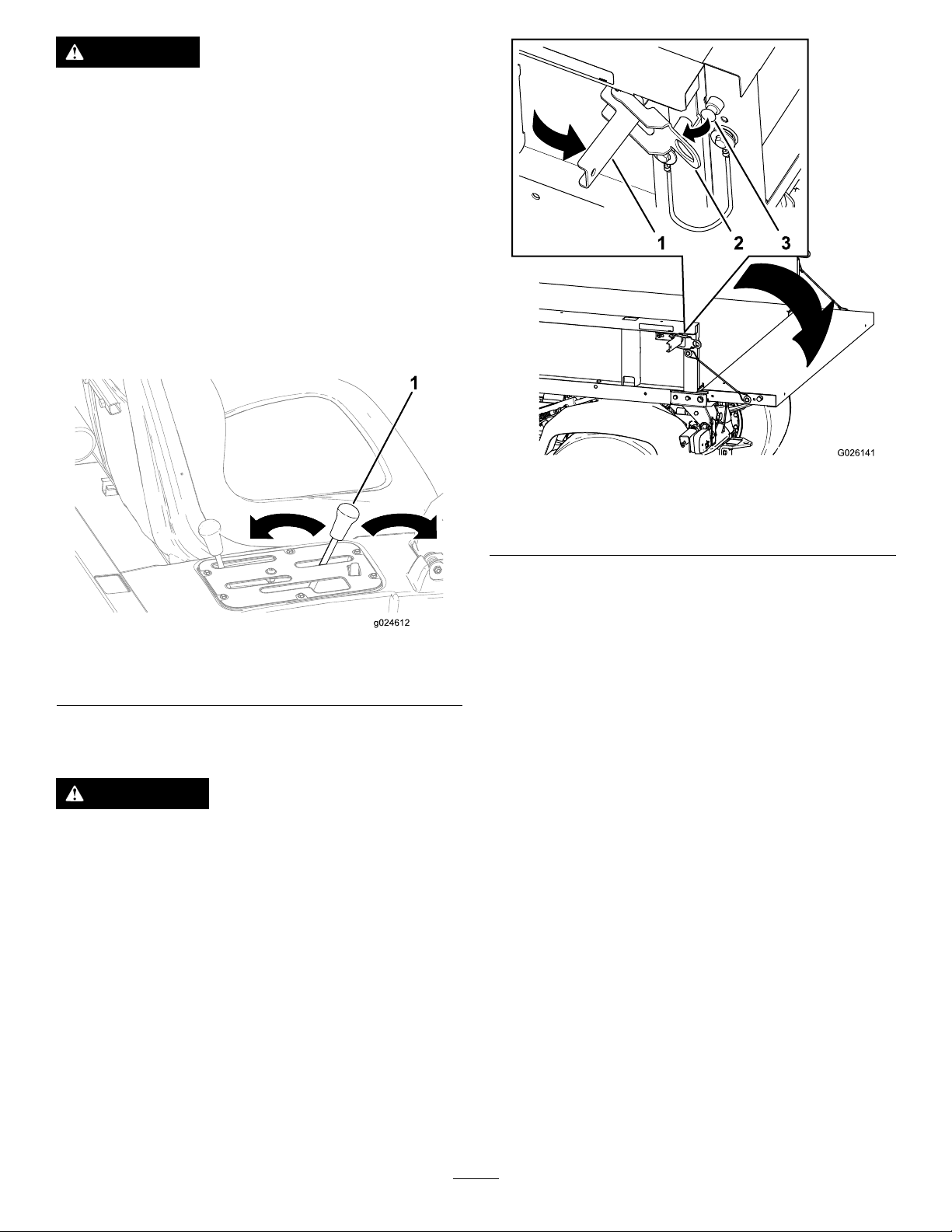
Movetheleverrearwardtoraisethecargobed
(Figure21).
g026141
Figure22
1.Latchhandle3.Latchpin
2.Latchgate
Figure21
1.Cargobedlever
LoweringtheCargoBed
WARNING
Theweightofthebedmaybeheavy.Hands
orotherbodypartscouldbecrushed.
Keepyourhandsandotherbodypartsaway
whenloweringthebed.
Movetheleverforwardtolowerthecargobed(Figure
21).
OpeningtheTailgate
1.Ensurethatthecargobedisdownandlatched.
2.Openthelatchesontheleftandrightsideofthe
cargobedandlowerthetailgate(Figure22).
StartingtheEngine
g024612
Important:Donotattempttopushortowthe
machinetogetitstarted.Damagetothedrive
traincouldresult.
1.Sitontheoperatorseatandengagetheparking
brake.
2.DisengagethePTOandthehigh-owhydraulics
(ifequipped)andmovethehand-throttleleverto
theOFFposition(ifequipped).
3.MovethetransmissionlevertotheP(PARK)
position.
4.Ensurethatthehydraulic-liftleverisintheOFF
position(center).
5.Pressthebrakepedal.
Note:Keepyourfootofftheacceleratorpedal.
6.Insertthekeyintothekeyswitchandrotateit
clockwisetostarttheengine.
Note:Releasethekeyswitchwhentheengine
starts.
Note:Theoil-pressurewarninglightshould
turnoff.
Important:Topreventoverheatingofthe
startermotor,donotengagestarterlonger
than15seconds.After15secondsof
26
Page 27
continuouscranking,wait60secondsbefore
engagingstartermotoragain.
UsingtheSpeed-Range
Control
DrivingtheMachine
1.Pressthebrakepedal.
2.Disengagetheparkingbrake.
3.Movethetransmissionlevertothedesiredgear.
4.Releasetheservicebrakeandgraduallypress
intheacceleratorpedal.
Important:Alwaysstopthemachinebefore
shiftingtoreverseaforwardgearortoa
forwardgearfromreverse.
Usethechartbelowtodeterminetheground
speedofeachgearwhenoperatingthe
machinewiththespeed-rangecontrolintheT
(TRANSPORT)position.
GearSpeed(km/h)Speed(mph)
R(REVERSE)
L(LOWFORWARD)
D(DRIVE)
Note:Avoididlingtheengineforlongperiods
oftime.
Note:LeavingthekeyswitchintheONposition
forlongperiodsoftimewithoutstartingthe
enginedischargesthebattery.
0to210to13
0to180to1 1
0to320to20
Usetheleverofthespeed-rangecontroltolimitthe
maximumgroundspeedofthemachineforoperations
thatrequireaconstantspeedlikesprayingandtop
dressing.Thespeed-rangelever(Figure23)isused
toselect1ofthe4work-speedrangesthatareused
tolimitmaximumgroundspeedoratransport-speed
rangethatisusedwhenyoumovethemachine
betweenjobsites.
Note:Youmustreleasetheacceleratorpedalin
ordertoshiftbetweenspeedranges,butyoudonot
needtostopthemachineinordertoshift.
•Movethespeed-rangeleverintothedetentfor
speedrangesA,B,C,andDwhenprecisecontrol
ofmaximum-groundspeedisdesired.
•Movethespeed-rangelevertotheT(TRANSPORT)
positionbymovingthespeed-rangeleveroutof
thedetentforrangeA,B,C,orD,thenforwardto
theT(TRANSPORT)position.
Note:Usethespeed-rangecontroltolimitthe
maximumgroundspeedineachrangeby4to18
km/h(2.5to11mph)withthetransmissionleverin
theL(LOWFORWARD)positionor8to32km/h(5to
20mph)withthetransmissionleverintheintheD
(DRIVE)position.
StoppingtheMachine
Tostopthemachine,removeyourfootfromthe
acceleratorpedal,thenpressthebrakepedal.
ShuttingOfftheEngine
1.Stopthemachine.
2.MovethetransmissionlevertotheP(PARK)
position.
3.Engagetheparkingbrake.
4.RotatethekeyswitchtotheOFFpositionand
removethekey.
g024320
Figure23
1.Speed-rangelever4.C(mid-highrange)
2.T(transportrange)5.B(mid-lowrange)
3.D(highrange)6.A(lowrange)
27
Page 28
UsingtheDifferentialLock
WARNING
Tippingorrollingthemachineonahillcan
causeaseriousinjury.
•Theextratractionavailablewiththe
differentiallockcanbeenoughtogetyou
intodangeroussituationssuchasclimbing
slopesthataretoosteeptoturnaround.
Beextracarefulwhenoperatingwiththe
differentiallockon,especiallyonsteeper
slopes.
•Ifthedifferentiallockisonwhenmakinga
sharpturnatahigherspeedandtheinside
rearwheelliftsofftheground,theremay
bealossofcontrol,whichcouldcausethe
machinetoskid.Usethedifferentiallock
onlyatslowerspeeds.
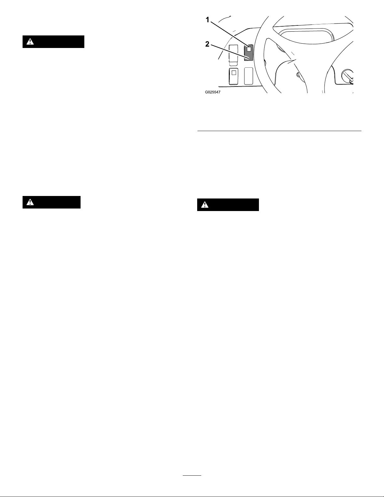
Figure24
1.Lockposition
(differential-lockswitch)
2.Unlockposition
(differential-lockswitch)
UsingtheHydraulicControl
Thehydrauliccontrolsupplieshydraulicpowerfrom
themachinepumpwhenevertheengineruns.You
canusethepowerthroughthequickcouplersatthe
rearofthemachine.
g025547
CAUTION
Turningwiththedifferentiallockoncanresult
inlossofmachinecontrol.Donotoperate
withdifferentiallockonwhenmakingsharp
turnsorathighspeeds.
Thedifferentiallockincreasesthetractionofthe
machinebylockingtherearwheelssothatawheel
doesnotspinout.Thiscanhelpwhenyouhave
heavyloadstohaul,onwetturforslipperyareas,
goinguphills,andonsandysurfaces.Itisimportant
torememberthatthisextratractionisonlyfor
temporary,limiteduse.Itsusedoesnotreplacethe
safeoperationalreadydiscussedconcerningsteep
hillsandheavyloads.
Thedifferentiallockcausestherearwheelstospin
atthesamespeed.Whenusingthedifferentiallock,
yourabilitytomakesharpturnsissomewhatrestricted
andmayscufftheturf.Usethedifferentiallockonly
whenneededandatslowerspeeds.
Note:Machinemotionplusaslightturnisrequiredto
engageordisengagedifferentiallock.
WARNING
Hydraulicuidescapingunderpressurecan
havesufcientforcetopenetrateskinand
cancauseseriousinjury.
Usecarewhenconnectingordisconnecting
hydraulicquickcouplers.Shutoffthe
engine,engagetheparkingbrake,lowerthe
attachment,andplacetheremotehydraulic
valveintheoatdetentpositiontorelieve
thehydraulicpressurebeforeconnectingor
disconnectingthequickcouplers.
Important:Ifmultiplemachinesusethe
sameattachment,cross-contaminationofthe
transmissionuidmayoccur.Changethe
transmissionuidmorefrequently.
•Pressthedifferential-lockswitchuptolockthe
differential(Figure24).
Note:Thelightinthedifferential-lockswitch
illuminateswhentheswitchisinthelockposition.
•Pressthedifferential-lockswitchuptounlockthe
differential(Figure24).
28
Page 29
UsingtheHydraulicBed-LiftLever
toControlHydraulicAttachments
•OFFPosition
Thisisthenormalpositionforthecontrolvalve
whenitisnotinuse.Inthisposition,thework
portsofthecontrolvalveareblockedandanyload
isheldbythecheckvalvesinbothdirections.
ThispositionissimilartotheLOWER(QUICK
COUPLERBPOSITION).Italsodirectshydraulicuid
toquickcouplerB,exceptthattheleverisheldin
thispositionbyadetentleverinthecontrolpanel.
Thisallowshydraulicuidtoowcontinuouslyto
equipmentthatuseahydraulicmotor.
Usethispositiononlyonattachmentswitha
hydraulicmotorattached.
•RAISE(QuickCouplerA)Position
Thispositionliftsthebedandrearhitch
attachment,orappliespressuretoquickcoupler
A.Thispositionalsoallowshydraulicuidtoreturn
fromquickcouplerBtoowbackintothevalve
andthenouttothereservoir.Thisisamomentary
position,andwhenyoureleasethelever,it
spring-returnstothecenter,OFFposition.
Important:Ifyouuseitwithahydraulic
cylinderornoattachment,theONposition
causesthehydraulic-uidowtogoovera
reliefvalve,whichcandamagethehydraulic
system.Usethispositiononlymomentarilyor
withamotorattached.
Important:Checkthehydraulic-uidlevel
afterinstallationofanattachment.Checkthe
operationoftheattachmentbycyclingthe
attachmentseveraltimestopurgeairfrom
thesystem,thencheckhydraulic-uidlevel
again.Theattachmentcylinderslightlyaffects
theuidlevelinthetransaxle.Operatingthe
machinewithalowhydraulic-uidlevelcan
damagethepump,remotehydraulics,power
steering,andmachinetransaxle.
ConnectingtheQuickCouplers
Important:Cleandirtfromthequickcouplers
beforeconnectingthem.Dirtycouplerscan
introducecontaminationintothehydraulic
system.
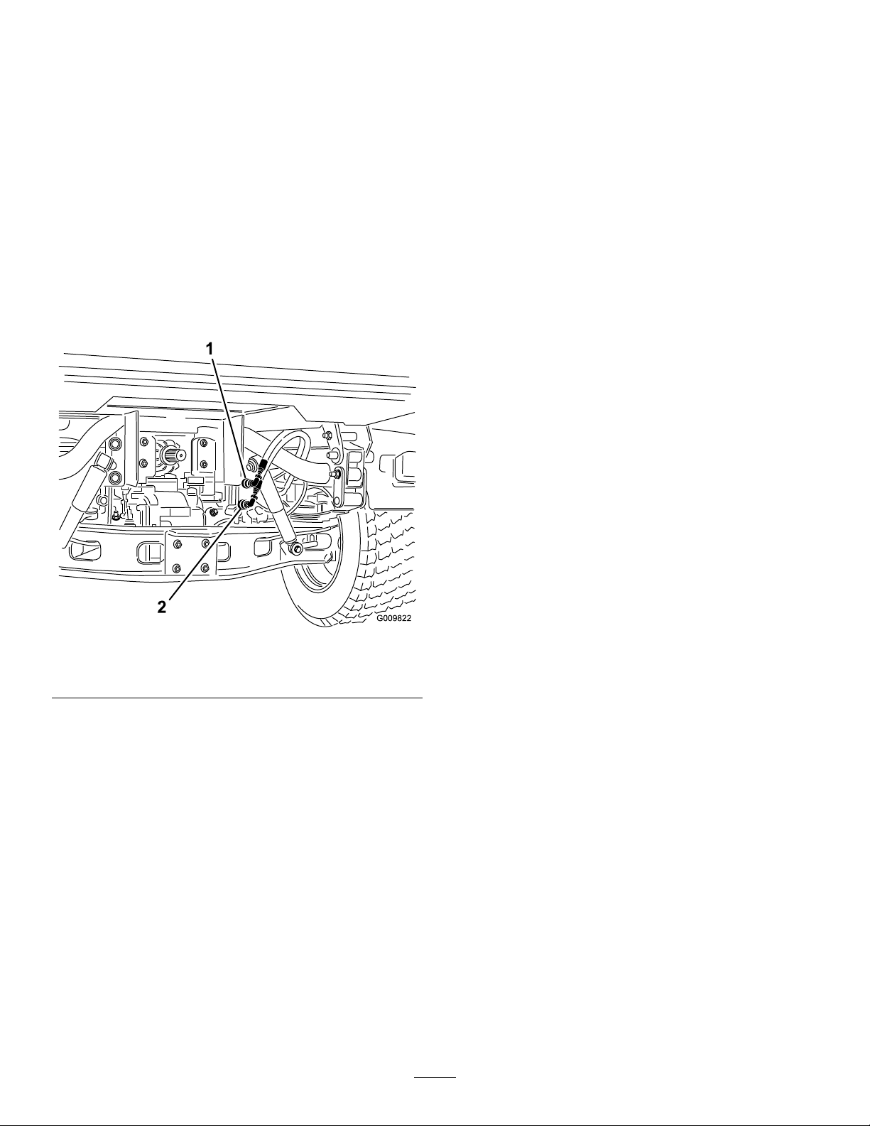
Figure25
1.QuickcouplerAposition2.QuickcouplerBposition
•LOWER(QuickCouplerB)Position
Thispositionlowersthebed,rearhitchattachment,
orappliespressuretoquickcouplerB.Thisalso
allowshydraulicuidtoreturnfromquickcoupler
Atoowbackintothevalveandthenouttothe
reservoir.Thisisamomentaryposition,andwhen
youreleasethelever,itspring-returnstothe
center,OFFposition.Momentarilyholdingandthen
releasingthecontrolleverinthispositionprovides
hydraulic-uidowtoquickcouplerB,which
providespowerdownontherearhitch.Whenyou
releaseit,itholdsthedown-pressureonthehitch.
Important:Ifyouuseitwithahydraulic
cylinder,holdingthecontrolleverinthelower
positioncausesthehydraulic-uidowto
gooverareliefvalve,whichcandamagethe
hydraulicsystem.
g009822
1.Pullbackthelockingringonthecoupler.
2.Insertthehosenippleintothecoupleruntilit
snapsintoposition.
Note:Whenattachingremoteequipmenttothequick
couplers,determinewhichsiderequirespressure,
thenattachthathosetoquickcouplerB,whichhas
pressurewhenyoupushthecontrolleverforwardor
lockedintheONposition.
DisconnectingtheQuickCouplers
Note:Withboththemachineandattachmentshut
off,movetheliftleverbackandforthtoremovethe
systempressureandeasethedisconnectionofthe
quickcouplers.
1.Pullbackthelockingringonthecoupler.
2.Pullthehosermlyfromthecoupler.
Important:Cleanandinstallthedustplug
anddustcoverstothequickcouplerends
whennotinuse.
•ONPosition
29
Page 30

TroubleshootingtheHydraulic
Control
AfterOperation
•Difcultyinconnectingordisconnectingquick
couplers.
Thepressureisnotrelieved(thequickcoupleris
underpressure).
•Thepowersteeringisturningwithgreat
difcultyoritisnotturningatall.
–Thehydraulic-uidlevelislow.
–Thehydraulic-uidtemperatureistoohot.
–Thepumpisnotoperating.
•Therearehydraulicleaks.
–Thettingsareloose.
–ThettingismissingtheO-ring.
•Anattachmentdoesnotfunction.
–Thequickcouplersarenotfullyengaged.
–Thequickcouplersareinterchanged.
•Thereisasquealingnoise.
–RemovethevalveleftintheONpositiondetent,
causinghydraulicuidtoowovertherelief
valve.
–Thebeltisloose.
•Theenginedoesnotstart.
AfterOperationSafety
GeneralSafety
•Beforeyouleavetheoperatingposition,dothe
following:
–Parkthemachineonalevelsurface.
–ShiftthetransmissiontotheNEUTRALposition.
–Engagetheparkingbrake.
–Lowerthecargobed.
–Shutoffthemachineandremovethekey(if
equipped).
–Waitforallmovementtostop
•Allowthemachinetocoolbeforeadjusting,
servicing,cleaning,orstoringit.
•Donotstorethemachinewherethereisanopen
ame,spark,orpilotlight,suchasonawater
heaterorotherappliance.
•Keepallpartsofthemachineingoodworking
conditionandallhardwaretightened.
•Maintainandcleantheseatbelt(s)asnecessary.
•Replaceallworn,damaged,ormissingdecals.
ThehydraulicleverislockedintheFORWARD
position.
30
Page 31
HaulingtheMachine
TowingtheMachine
•Usecarewhenloadingorunloadingthemachine
intoatraileroratruck.
•Usefull-widthrampsforloadingthemachineinto
atraileroratruck.
•Tiethemachinedownsecurely.
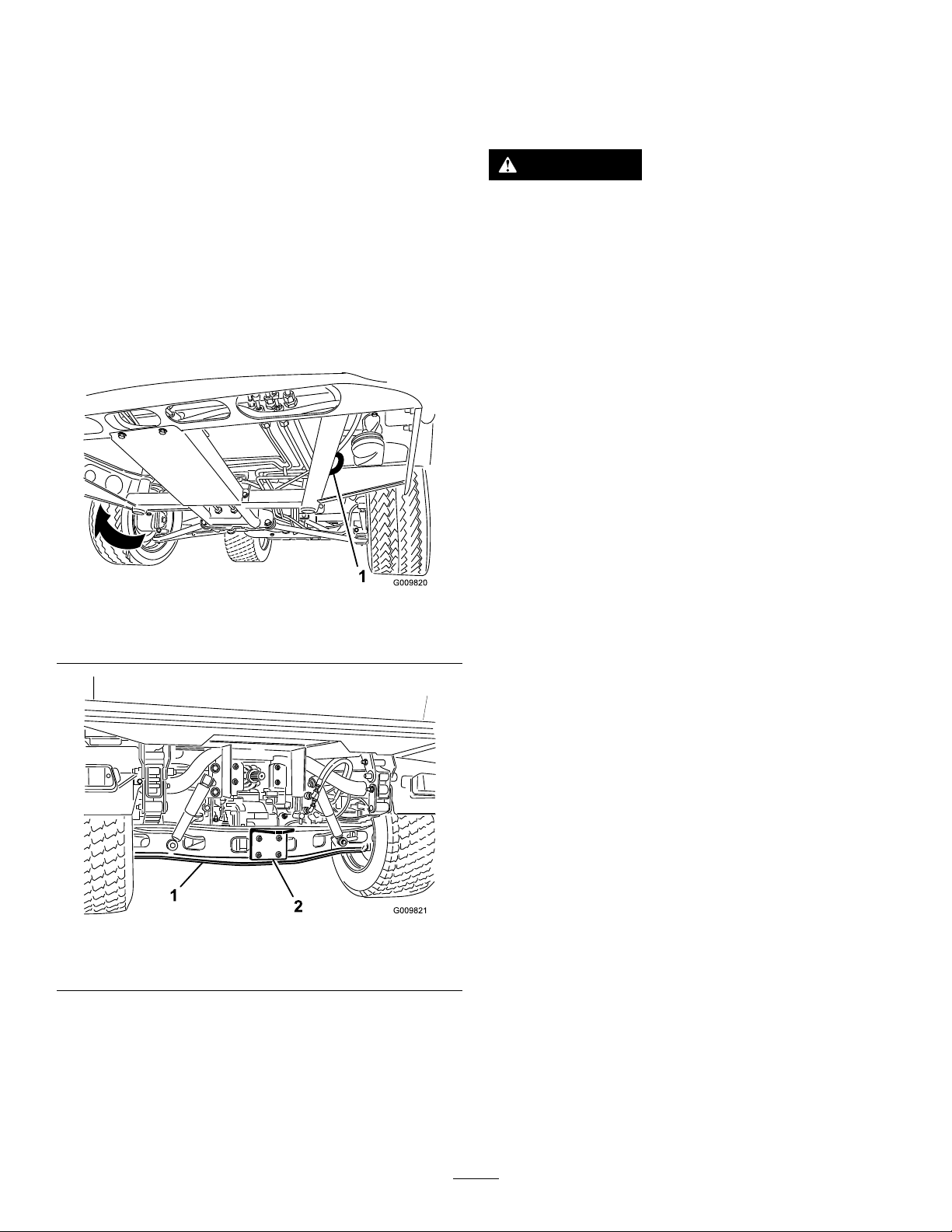
RefertoFigure26andFigure27forthetie-down
locationsonthemachine.
Note:Loadthemachineonthetrailerwiththefront
ofthemachinefacingforward.Ifthatisnotpossible,
securethemachinehoodtotheframewithastrap,
orremovethehoodandtransportandsecureit
separately;otherwise,thehoodmayblowoffduring
transport.
Incaseofanemergency,youcantowthemachine
forashortdistance;however,thisisnotthestandard
operatingprocedure.
WARNING
Towingatexcessivespeedscouldcausea
lossofsteeringcontrol,resultinginpersonal
injury.
Nevertowthemachineatfasterthan8km/h
(5mph).
Note:Thepowersteeringdoesnotfunction,
makingitdifculttosteer.
Towingthemachineisa2-personjob.Ifyoumust
movethemachineaconsiderabledistance,transport
itonatruckortrailer.
1.Afxatowlinetothetongueatthefrontofthe
frameofthemachine(Figure26).
2.MovethetransmissiontotheNEUTRALposition
anddisengagetheparkingbrake.
Figure26
1.Eyeholeintheframe(eachside)
Figure27
1.Axle2.Hitchplate
TowingaTrailer
g009820
g009821
Themachineiscapableofpullingtrailersand
attachmentsofgreaterweightthanthemachineitself.
Severaltypesoftowhitchesareavailableforthe
machine,dependingonyourapplication.Contactyour
AuthorizedServiceDealerfordetails.
Whenequippedwithatowhitchboltedontothe
rearaxletube,yourmachinecantowtrailersor
attachmentswithamaximumgrosstrailerweight
(GTW)upto1587kg(3,500lb).
Alwaysloadatrailerwith60%ofthecargoweightin
thefrontofthetrailer.Thisplacesapproximately10%
(272kg(600lb)maximum)ofthegrosstrailerweight
(GTW)onthetowhitchofthemachine.
Whenhaulingcargoortowingatrailer(attachment),
donotoverloadthemachineortrailer.Overloading
cancausepoorperformanceordamagetothebrakes,
axle,engine,transaxle,steering,suspension,body
structure,ortires.
Important:T oreducepotentialfordriveline
damage,uselowrange.
Whentowingfth-wheelattachments,likeafairway
aerator,alwaysinstallthewheelbar(includedwiththe
fthwheelkit)topreventthefrontwheelsfromlifting
offthegroundifthetowedattachmentsmovementis
suddenlyimpaired.
31
Page 32

Maintenance
MaintenanceSafety
•Donotallowuntrainedpersonneltoservicethe
machine.
•Beforeyouleavetheoperatingposition,dothe
following:
–Parkthemachineonalevelsurface.
–ShiftthetransmissiontotheNEUTRALposition.
–Engagetheparkingbrake.
–Lowerthecargobed.
–Shutoffthemachineandremovethekey(if
equipped).
–Waitforallmovementtostop
•Allowthemachinetocoolbeforeadjusting,
servicing,cleaning,orstoringit.
•Supportthemachinewithjackstandswhenever
youworkunderthemachine.
•Donotworkunderaraisedbedwithouttheproper
bedsafetysupportinplace.
•Ensurethatallhydraulic-lineconnectorsaretight
andthatallthehydraulichosesandlinesarein
goodconditionbeforeapplyingpressuretothe
system.
•Beforedisconnectingorperforminganyworkon
thehydraulicsystem,relieveallpressureinthe
systembyshuttingoffthemotor,cyclingthedump
valvefromraisetolower,and/orloweringthecargo
bedandattachments.Placetheremotehydraulics
leverintheoatposition.Ifthebedmustbein
raisedposition,secureitwiththesafetysupport.
•Carefullyreleasepressurefromcomponentswith
storedenergy.
•Donotchargethebatterieswhileservicingthe
machine.
•Toensurethattheentiremachineisingood
condition,keepallhardwareproperlytightened.
•Toreducethepotentialrehazard,keepthe
machineareafreeofexcessivegrease,grass,
leaves,andaccumulationofdirt.
•Ifpossible,donotperformmaintenancewhilethe
machineisrunning.Keepawayfrommovingparts.
•Ifyoumustrunthemachinetoperforma
maintenanceadjustment,keepyourhands,feet,
clothing,andanypartsofthebodyawayfrom
anymovingparts.Keepbystandersawayfrom
themachine.
•Cleanupoilandfuelspills.
•Checktheparkingbrakeoperationas
recommendedinthemaintenancescheduleand
adjustandserviceitasrequired.
•Keepallpartsofthemachineingoodworking
conditionandallthehardwareproperlytightened.
Replaceallwornordamageddecals.
•Neverinterferewiththeintendedfunctionofa
safetydeviceorreducetheprotectionprovided
byasafetydevice.
•Donotoverspeedtheenginebychangingthe
governorsettings.T oensuresafetyandaccuracy,
haveanAuthorizedServiceDealercheckthe
maximumenginespeedwithatachometer.
•Ifmajorrepairsareevernecessaryorassistance
isrequired,contactanAuthorizedServiceDealer.
•Alteringthismachineinanymannermayaffectthe
operationofthemachine,performance,durability,
oritsusemayresultininjuryordeath.Suchuse
couldvoidtheproductwarrantyofTheT oro®
Company.
RecommendedMaintenanceSchedule(s)
MaintenanceService
Interval
Aftertherst2hours
Aftertherst10hours
Aftertherst50hours
Aftertherst100hours
MaintenanceProcedure
•T orquethefrontandrearwheelnuts.
•T orquethefrontandrearwheelnuts.
•Checktheadjustmentoftheparkingbrake.
•Changetheengineoilandlter.
•Inspecttheopeningonthelter.
•Checkthetransmission-uidlevel.
•Performtheguidelinesforbreakinginanewmachine.
32
Page 33

MaintenanceService
Interval
Beforeeachuseordaily
MaintenanceProcedure
•Inspecttheseatbelt(s)forwear,cuts,andotherdamage.Replacetheseatbelt(s)if
anycomponentdoesnotoperateproperly.
•Checkthetirepressure.
•Checktheoperationofthesafety-interlocksystem.
•Checktheengine-oillevel.(Checktheoillevelbeforeandaftertheengineisrst
startedanddailythereafter.)
•Checktheoil-pressure-warninglight.
•Checkthelevelofthecoolant.ChecktheCoolantlevelattheoverowreservoir
only.Donotremovetheradiatorcap.(Checkthecoolantlevelbeforetheengineis
rststartedanddailythereafter.)
•Removedebrisfromtheengineareaandradiator.(Cleanitmorefrequentlyin
dirtyconditions.)
•Checkthebrake-uidlevel.(Checkthelevelbeforetheengineisrststartedand
dailythereafter.)
•Checkthehydraulic-uidlevel.(Checkthelevelofhydraulicuidbeforetheengine
isrststartedanddailythereafter.)
•Washthemachine.
Every25hours
Every50hours
Every100hours
Every200hours
Every400hours
Every800hours
•Removetheair-cleanercoverandcleanoutthedebris.
•Checkthebattery-uidlevel(every30daysifinstorage).
•Checkthebatterycableconnections.
•Greasethebearingsandbushings(lubricatemorefrequentlyinheavy-duty
applications).
•Changetheair-cleanerlter(morefrequentlyindustyordirtyconditions).
•Checkthesparkplugs.
•Inspecttheconditionofthetires.
•Checktheconstant-velocitybootsfordamageandleakinglubricant.
•Changetheengineoilandlter.
•Changethecarboncanisterairlter.
•T orquethefrontandrearwheelnuts
•Checktheuidlevelinthereservoirforthespeed-controlcylinder.
•Checktheadjustmentoftheparkingbrake.
•Checktheadjustmentofthebrakepedal.
•Inspecttheserviceandparkingbrakes.
•Replacethefuellter.
•Inspectthefuellinesandconnections.
•Checkthefrontwheelalignment.
•Checkthetransmission-uidlevel.
•Checktheconditionofthedrivebelt.
•Cleantheclutches.
•Visuallyinspectthebrakesforwornbrakeshoes.
•Ifyouarenotusingtherecommendedhydraulicuidorhaveeverlledthereservoir
withanalternativeuid,replacethehydraulicuidandlter.
Every1,000hours
Every2,000hours
•Flush/replacethecoolantsystemuid.
•Changethebrakeuid.
•Ifyouareusingtherecommendedhydraulicuid,replacethehydrauliclter.
•Ifyouareusingtherecommendedhydraulicuid,changethehydraulicuid.
Yearly
•Completealloftheyearlymaintenanceproceduresspeciedintheengineowner’s
manual.
33
Page 34

Note:Downloadafreecopyoftheelectricalschematicbyvisitingwww.Toro.comandsearchingforyour
machinefromtheManualslinkonthehomepage.
Important:Refertoyourengineowner’smanualforadditionalmaintenanceprocedures.
WARNING
Failingtoproperlymaintainthemachinecouldresultinprematurefailureofmachinesystems,
causingpossibleharmtoyouorbystanders.
Keepthemachinewellmaintainedandingoodworkingorderasindicatedintheseinstructions.
CAUTION
Onlyqualiedandauthorizedpersonnelshouldmaintain,repair,adjust,orinspectthemachine.
•Avoidrehazardsandhavere-protectionequipmentpresentintheworkarea.Donotuse
anopenametocheckuidlevelsorleakageoffuel,batteryelectrolyte,orcoolant.
•Donotuseopenpansoffuelorammablecleaninguidsforcleaningparts.
CAUTION
Ifyouleavethekeyintheswitch,someonecouldaccidentlystarttheengineandseriously
injureyouorotherbystanders.
Shutofftheengineandremovethekeyfromtheswitchbeforeyouperformanymaintenance.
MaintainingtheMachineunderSpecialOperating
Conditions
Important:Ifthemachineissubjectedtoanyoftheconditionslistedbelow,performmaintenance
twiceasfrequently:
•Desertoperation
•Coldclimateoperation—below10°C(50°F)
•Trailertowing
•Frequentoperationindustyconditions
•Constructionwork
•Afterextendedoperationinmud,sand,water,orsimilardirtyconditions,dothefollowing:
–Haveyourbrakesinspectedandcleanedassoonaspossible.Thispreventsanyabrasivematerial
fromcausingexcessivewear.
–Washthemachineusingwateraloneorwithamilddetergent.
Important:Donotusebrackishorreclaimedwatertocleanthemachine.
34
Page 35
Pre-Maintenance
Procedures
PreparingtheMachinefor
Maintenance
1.Parkthemachineonalevelsurface.
2.Engagetheparkingbrake.
3.Emptyandraisethecargobed;refertoRaising
theCargoBed(page25).
4.Shutofftheengineandremovethekey.
5.Allowthemachinetocoolbeforeperforming
maintenance.
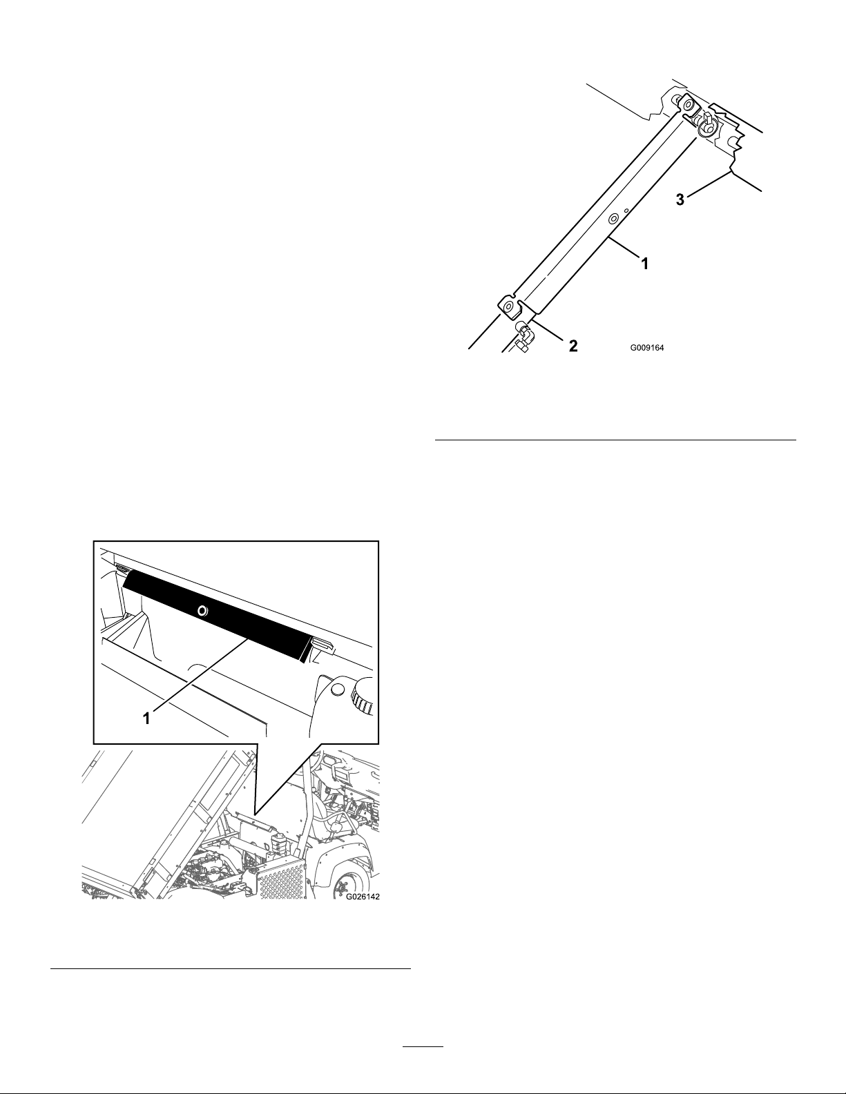
UsingtheBedSupport
Important:Alwaysinstallorremovethebed
supportfromtheoutsideofthebed.
endofthecylinderbarrelandcylinder-rodend
(Figure29).
g009164
Figure29
1.Bedsupport3.Bed
2.Cylinderbarrel
1.Raisethebeduntiltheliftcylindersarefully
extended.
2.Removethebedsupportfromthestorage
bracketsonthebackoftheROPSpanel(Figure
28).
4.Removethebedsupportfromthecylinder,and
insertitintothebracketsonthebackofthe
ROPSpanel.
Important:Donottrytolowerthebedwith
thebed-safetysupportonthecylinder.
Figure28
1.Bedsupport
3.Pushthebedsupportontothecylinderrod,and
ensurethatthesupport-endtabsrestonthe
g026142
35
Page 36
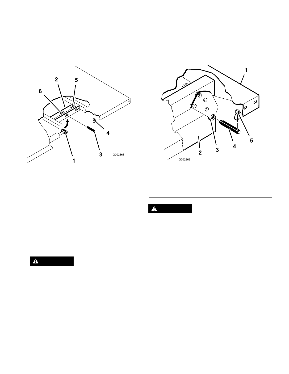
RemovingtheFullBed
InstallingtheFullBed
1.Starttheengine,engagethehydraulic-liftlever,
andlowerthebeduntilthecylindersareloose
intheslots.
2.Releasetheliftleverandshutofftheengine.
3.Removethelynchpinsfromtheouterendsof
thecylinderrodclevispins(Figure30).
Note:Ifyouareinstallingthebedsidesontheat
bed,itiseasiertoinstallthembeforeinstallingthe
bedonthemachine.
Ensurethattherearpivotplatesareboltedtothebed
frame/channelsothatthelowerendanglestotherear
(Figure31).
Figure30
1.Cylinderrodend
2.Bed-mountingplate
3.Clevispin6.Frontslots(2/3fullbed)
4.Removetheclevispinssecuringthecylinderrod
endstothebed-mountingplatesbypushingthe
pinstowardtheinside(Figure30).
5.Removethelynchpinsandclevispinssecuring
thepivotbracketstotheframechannels(Figure
30).
6.Liftthebedoffthemachine.
4.Lynchpin
5.Rearslots(fullbed)
CAUTION
Thefullbedweighsapproximately148kg
(325lb),sodonottrytoinstallorremove
itbyyourself.
Useanoverheadhoistorgetthehelpof
2or3otherpeople.
g002368
1.Left,rearcornerofbed4.Clevispin
2.Machineframechannel
3.Pivotplate
Figure31
5.Lynchpin
g002369
CAUTION
Thefullbedweighsapproximately148kg
(325lb),sodonottrytoinstallorremoveit
byyourself.
Useanoverheadhoistorgetthehelpof2or3
otherpeople.
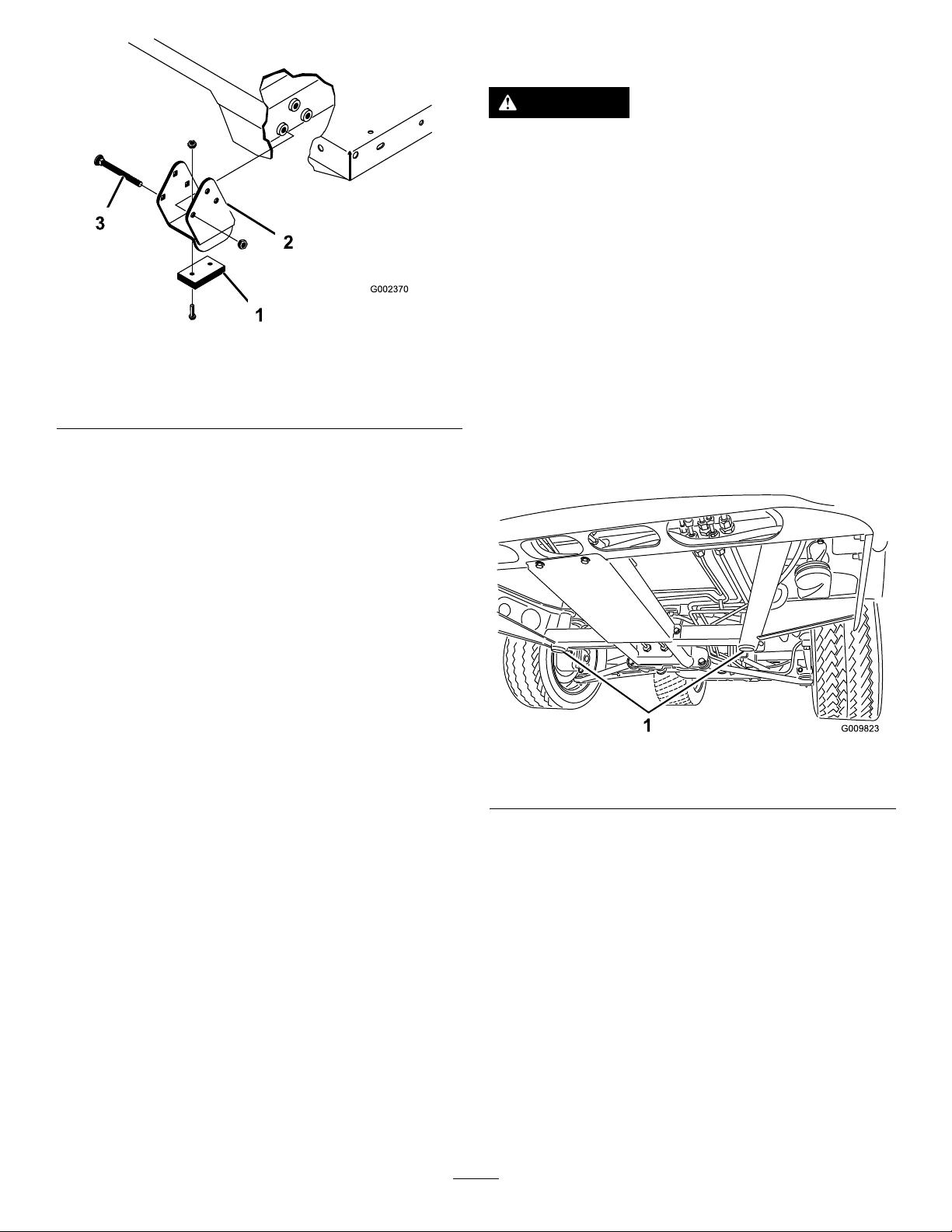
Ensurethatthespacerbracketsandwearblocks
(Figure32)areinstalledwiththecarriage-boltheads
positionedinsidethemachine.
7.Storethecylindersinthestorageclips.
8.Engagethehydrauliclift-lockleveronthe
machinetopreventaccidentalextensionofthe
liftcylinders.
36
Page 37
RaisingtheMachine
DANGER
Amachineonajackmaybeunstableandslip
offthejack,injuringanyonebeneathit.
•Donotstartthemachinewhilethemachine
isonajack,astheenginevibrationor
wheelmovementcouldcausethemachine
toslipoffthejack.
•Alwaysremovethekeyfromthekeyswitch
beforegettingoffthemachine.
Figure32
1.Wearblock
2.Spacerbracket
1.Ensurethattheliftcylindersarefullyretracted.
2.Carefullysetthebedontothemachineframe,
aligningtherearbedpivot-plateholeswiththe
holesintherearframechannel,andinstallthe2
clevispinsandlynchpins(Figure32).
3.Withthebedlowered,secureeachcylinderrod
endtotheappropriateslotsinthebed-mounting
plateswithaclevispinandlynchpin.
4.Inserttheclevispinfromoutsideofthebedwith
thelynchpinorientedtowardtheoutside(Figure
32).
3.Carriagebolt
Note:Therearslotsareforafullbed
installation;thefrontslotsarefora2/3-fullbed
installation.
Note:Y oumayneedtostarttheengineto
extendorretractthecylindersforalignmentwith
theholes.
g002370
•Blockthetireswhenthemachineisona
jack.
Whenjackingupthefrontofthemachine,always
placeawoodenblock(orsimilarmaterial)between
thejackandthemachineframe.
Thejackingpointatthefrontofthemachineislocated
underthefront,centerframesupport(Figure33).
g009823
Figure33
1.Frontjackingpoints
Note:Y oucanplugtheunusedslotwithabolt
andnuttopreventassemblyerrors.
5.Starttheengineandengagethehydraulic-lift
levertoraisethebed.
6.Releasetheliftleverandshutofftheengine.
7.Installthebed-safetysupporttoprevent
accidentallyloweringthebed;refertoUsingthe
BedSupport(page35).
8.Installthelynchpinstotheinsideendsofthe
clevispins.
Note:Iftheautomatictailgatereleaseis
installedonthebed,ensurethatthefrontdump
linkrodisplacedontheinsideoftheleftclevis
pinbeforeyouinstallthelynchpin.
Thejackingpointattherearofthemachineislocated
undertheaxle(Figure34).
37
Page 38
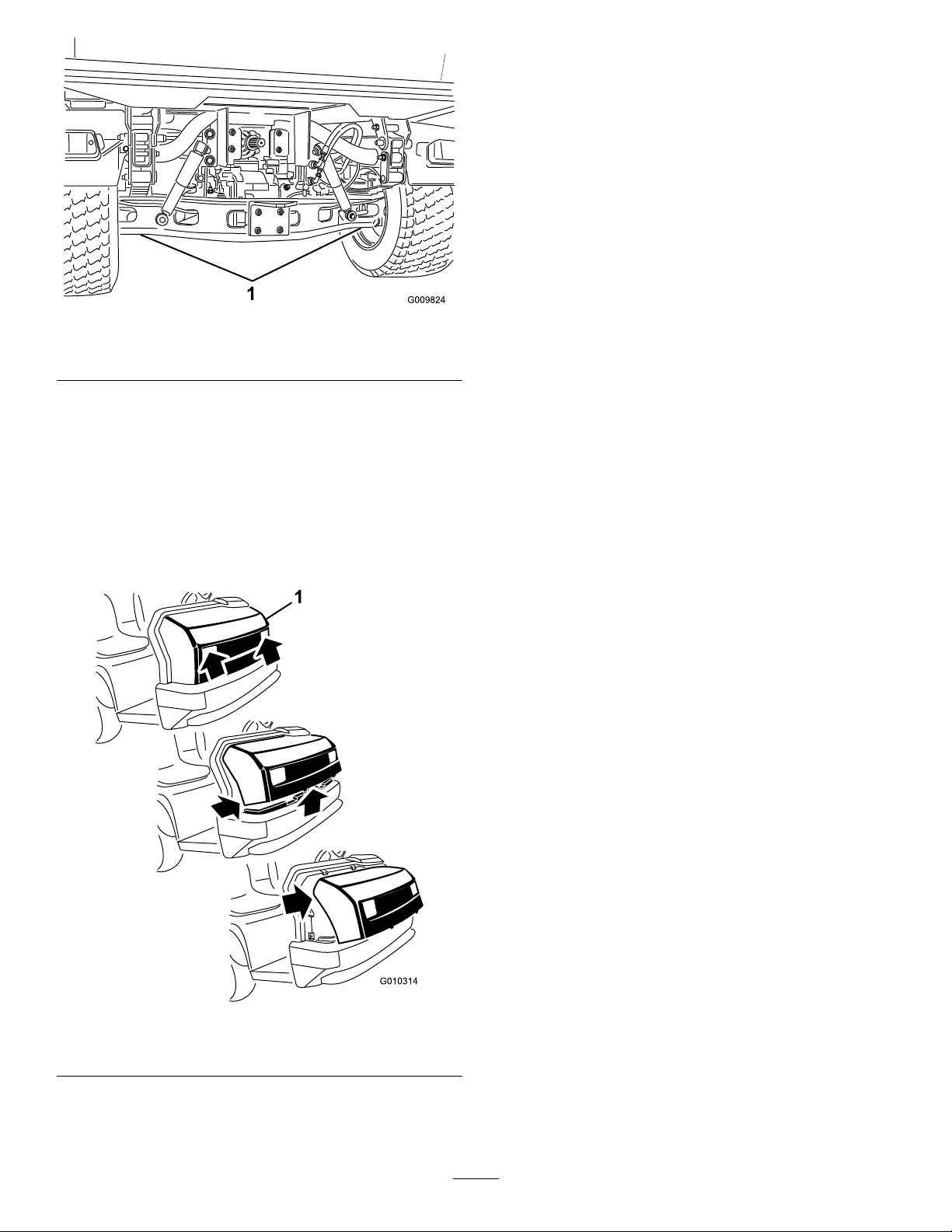
3.Pivotthetopofthehoodforwardandunplugthe
wireconnectorsfromtheheadlights(Figure35).
4.Removethehood.
InstallingtheHood
1.Connectthelights.
2.Insertthetopmountingtabsintotheframeslots
(Figure35).
3.Insertthelowermountingtabsintotheframe
slots(Figure35).
Figure34
1.Rearjackingpoints
RemovingandInstalling
theHood
RemovingtheHood
1.Whilegraspingthehoodintheheadlight
openings,liftupthehoodtoreleasethelower
mountingtabsfromtheframeslots(Figure35).
g009824
4.Ensurethatthehoodisfullyengagedinthetop,
sides,andbottomgrooves.
Figure35
1.Hood
2.Pivotthebottomofthehoodupwarduntilyou
canpullthetopmountingtabsfromtheframe
slots(Figure35).
g010314
38
Page 39
Lubrication
GreasingtheBearingsand
theBushings
ServiceInterval:Every100hours(lubricate
morefrequentlyinheavy-duty
applications).
GreaseType:No.2lithiumgrease
Important:Whengreasingthedriveshaft
universalshaftbearingcrosses,pumpgrease
untilitcomesoutofall4cupsateachcross.
1.Usearagtowipethegreasettingcleansothat
foreignmattercannotbeforcedintothebearing
orbushing.
2.Withagreasegun,applygreaseintothegrease
ttingsonthemachine.
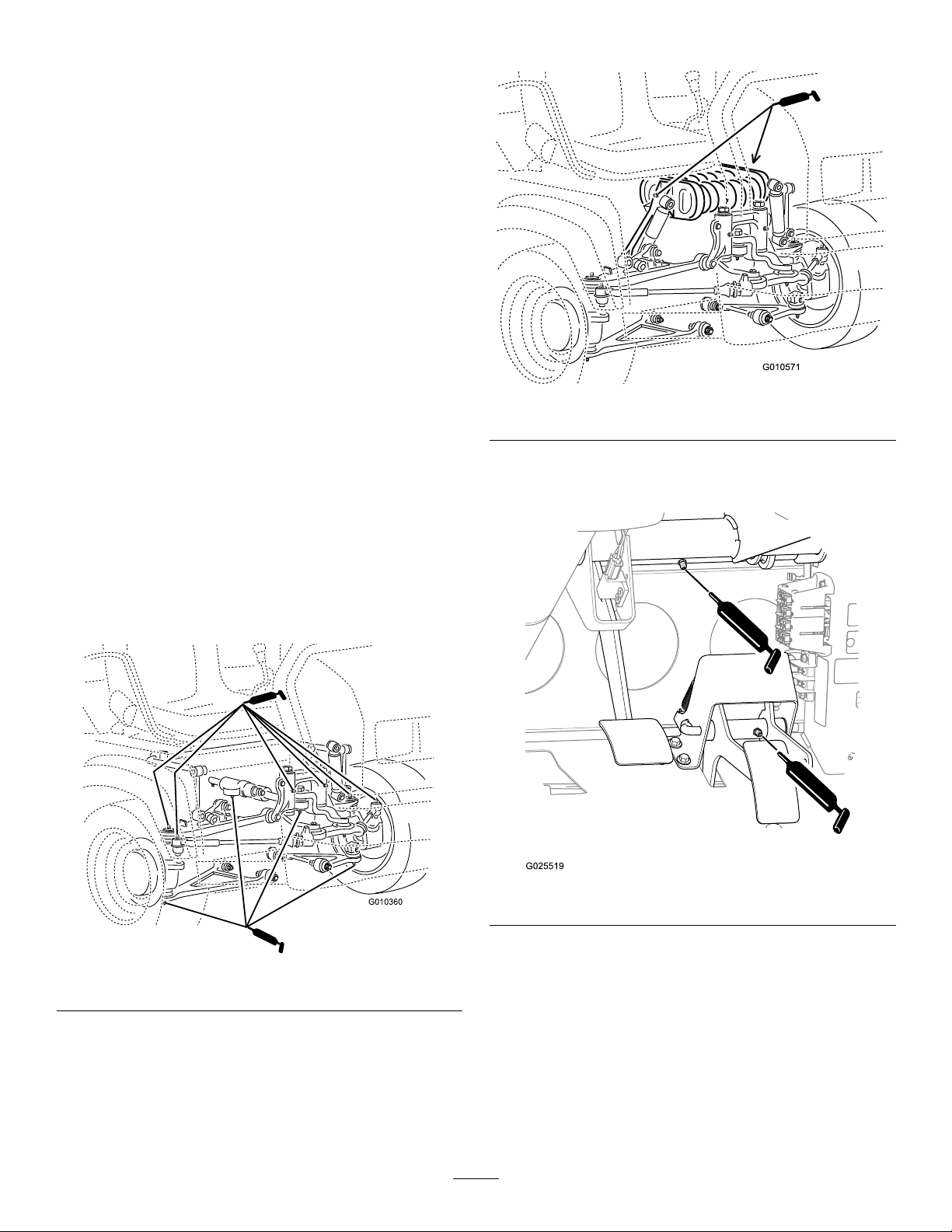
•Springtower(2);refertoFigure37
g010571
Figure37
3.Wipeanyexcessgreaseoffthemachine.
Thegreasettinglocationsandquantitiesareas
follows:
•Balljoints(4);refertoFigure36
•Pivotmounts(2);refertoFigure36
•Steeringcylinder(2);refertoFigure36
•Tierods(2);refertoFigure36
•Brake(1);refertoFigure38
•Throttle(1);refertoFigure38
g025519
Figure38
Figure36
g010360
39
Page 40
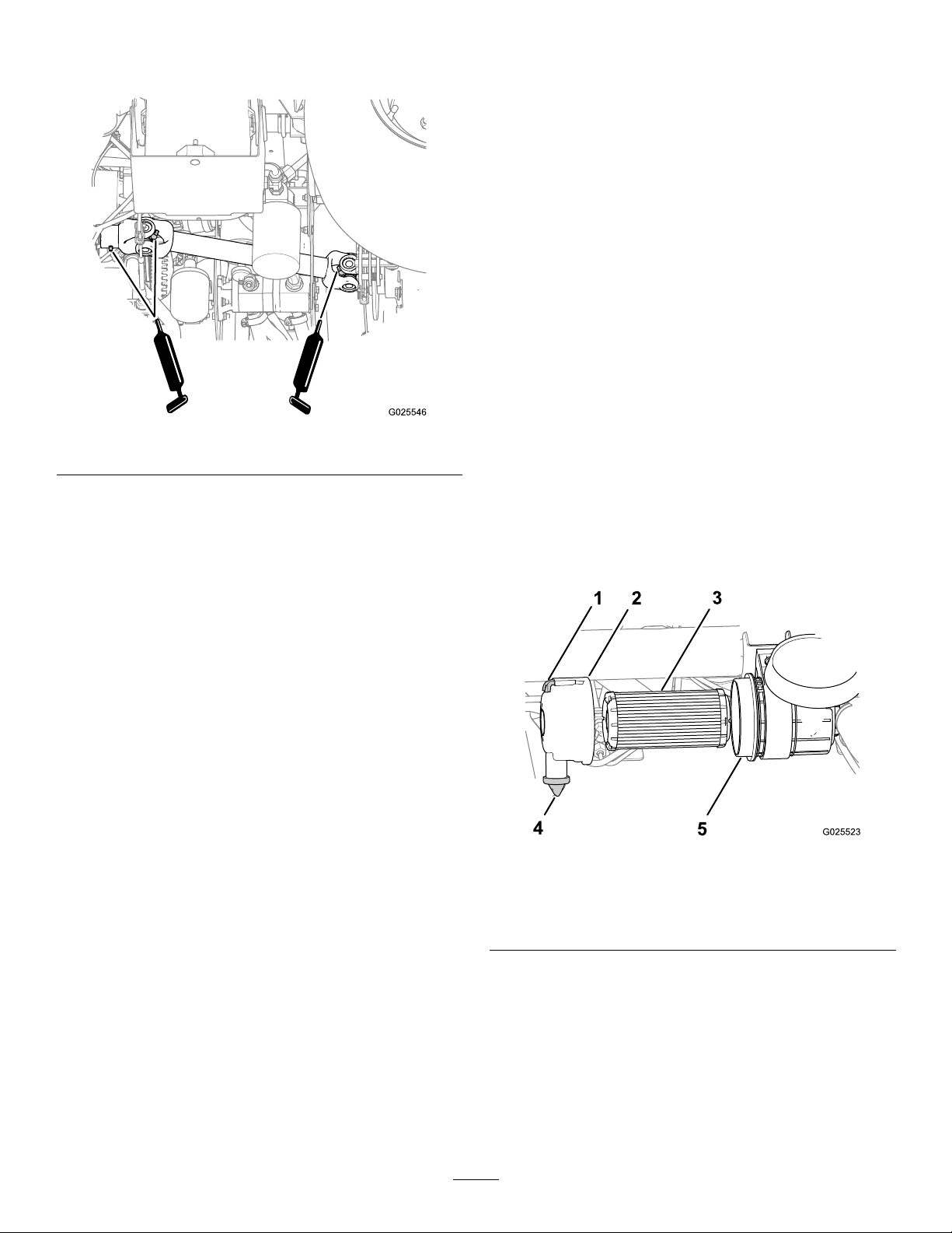
•DriveshaftU-joints(2);refertoFigure39
•Slidingyolk(1);refertoFigure39
Figure39
EngineMaintenance
EngineSafety
•Shutofftheengine,removethekey ,andwaitfor
allmovingpartstostopbeforecheckingtheoilor
addingoiltothecrankcase.
•Keepyourhands,feet,face,clothing,andother
bodypartsawayfromthemuferandotherhot
surfaces.
ServicingtheAirFilter
ServiceInterval:Every25hours—Removethe
air-cleanercoverandcleanoutthe
debris.
Every100hours—Changetheair-cleanerlter
g025546
(morefrequentlyindustyordirtyconditions).
Inspecttheairlterandhosesperiodicallytomaintain
maximumengineprotectionandtoensuremaximum
servicelife.Checktheair-ltercoverandhousingfor
damage,whichcouldcauseanairleak.Replaceany
damagedair-ltercomponents.
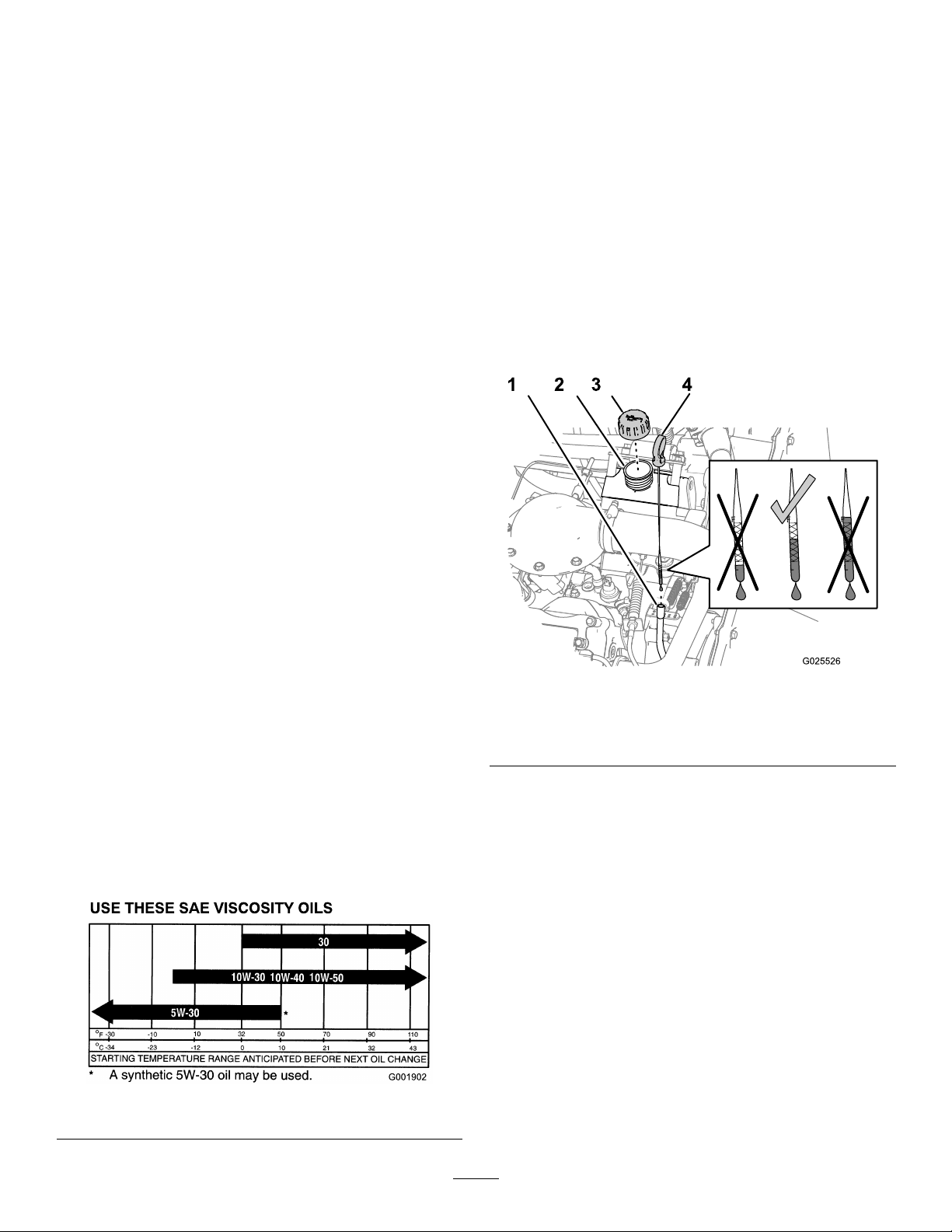
1.Pullthelatchoutwardandrotatetheair-lter
covercounterclockwise(Figure40).
Figure40
1.Latch4.Dustvalve
2.Air-ltercover
3.Airlter
2.Beforeremovingthelter,uselow-pressure
air(40psi,cleananddry)toremovelarge
accumulationsofdebrispackedbetweenthe
outsideoftheairlterandtheair-lterhousing.
5.Air-lterhousing
g025523
Important:Avoidusinghigh-pressureair,
whichcouldforcedirtthroughthelter
intotheintaketract.Thiscleaningprocess
preventsdebrisfrommigratingintothe
intakewhentheprimarylterisremoved.
40
Page 41
3.Removetheairlterfromthehousing(Figure
40).
Note:Donotcleanausedlterelement
becauseyoumaydamagetheltermedia.
4.Wipecleantheinterioroftheair-ltercoverand
housing(Figure40).
5.Removetherubberdustvalvefromthecover
(Figure40).
6.Cleanthedirt-ejectionportlocatedinthe
air-cleanercover,thedust-valvecavity,and
replacethedustvalve(Figure40).
7.Inspectthenewairlterforshippingdamage,
checkingthesealingendofthelterandthe
body.
Important:Donotuseadamagedelement.
8.Insertthenewairlterbyapplyinglightpressure
totheouterrimoftheltertoseatitinthe
air-lterhousing(Figure40).
9.Aligntheair-ltercoverwiththedustvalveatthe
6o’clockpositionwhenviewedfromtheleftend
ofthecover(Figure40).
10.Securethelatchoftheair-ltercover(Figure
40).
CheckingtheEngine-OilLevel
ServiceInterval:Beforeeachuseordaily—Check
theengine-oillevel.(Checktheoil
levelbeforeandaftertheengineis
rststartedanddailythereafter.)
Note:Thebesttimetochecktheengineoiliswhen
theengineiscoolbeforeithasbeenstartedforthe
day.Iftheenginehasalreadyran,shutitoffandwait
foratleast10minutesbeforecheckingtheoillevel.
1.Parkthemachineonalevelsurface.
2.Engagetheparkingbrake.
3.Shutofftheengineandremovethekey.
4.Removethedipstickandwipeitwithacleanrag
(Figure42).
Note:Resettheindicatorifitshowsred(if
equipped).
ServicingtheEngineOil
Note:Changetheoilmorefrequentlywhenoperating
conditionsareextremelydustyorsandy .
Note:Disposeoftheusedengineoilandoillterata
certiedrecyclingcenter.
Engine-OilSpecications
OilType:Detergentengineoil(APISJorhigher)
CrankcaseCapacity:2.0L(2.1USqt)whenthe
lterischanged
Viscosity:Seethetablebelow.
g025526
Figure42
1.Dipsticktube3.Fillercap
2.Fillerneck4.Dipstick
5.Insertthedipstickintothetubeandensurethat
itseatsfully.
6.Removedipstickandchecktheoillevel(Figure
42).
7.Iftheoillevelislow,removethellercap(Figure
42)andaddenoughoiltoraisetheleveltothe
Fullmarkonthedipstick.
Note:Whenaddingoil,removedipstickto
allowproperventing.Slowlypourtheoilintothe
llerneck,andchecktheleveloftenduringthis
process.Donotoverlltheenginewithoil.
Figure41
g001902
41
Page 42
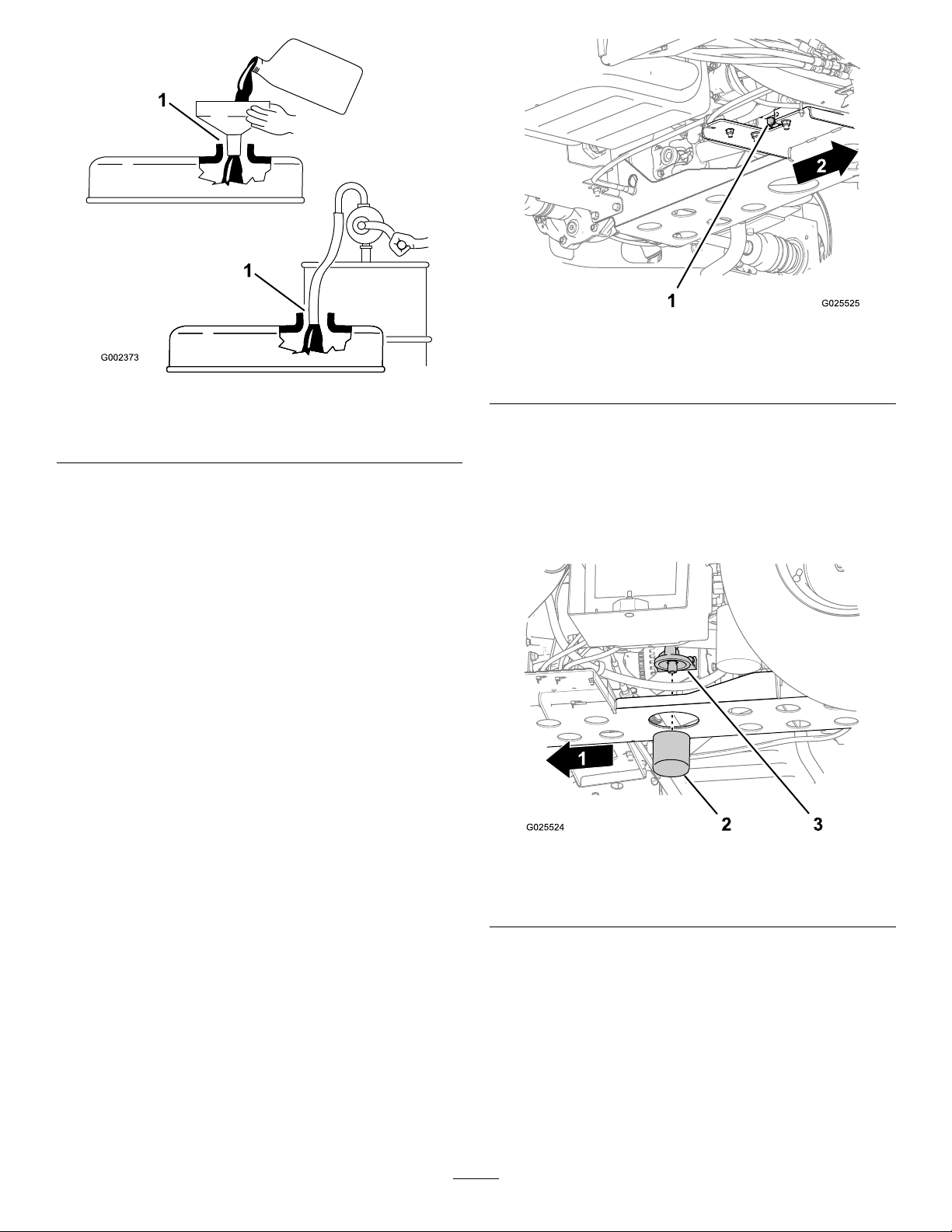
Figure43
g025525
Figure44
1.Drainplug
g002373
2.Forward
1.Notetheclearancebetweenthelldeviceandtheoil-ll
neck.
Important:Whenaddingengineoilorlling
oil,theremustbeclearancebetweentheoil
lldeviceandtheoilllneckinthevalve
coverasshowninFigure43.Thisclearance
isnecessarytopermitventingwhenadding
oil.
8.Installthellercapontothellerneck(Figure
42).
9.Firmlyinstallthedipstick(Figure42).
ChangingtheEngineOilandFilter
ServiceInterval:Aftertherst50hours
Every200hours
1.Raisethebedandplacethesafetysupporton
theextendedliftcylindertoholdupthebed.
2.Alignalargedrainpanundertheoil-drainplug
(Figure44).
3.Removethedrainplugandlettheoilowintoa
drainpan(Figure44).
4.Whentheoilstopsdraining,installthedrain
plug.
5.Removetheoillterfromthelteradapter
(Figure45).
g025524
Figure45
1.Forward3.Filteradapter
2.Oillter
6.Wipecleanthesealingbaseoftheofthelter
adapter(Figure45).
7.Applyalightcoatofcleanoiltothesealofthe
newlter.
8.Installthelteruntilthegasketcontactsthe
sealingbaseofthelteradapter,thentighten
thelterclockwiseandadditional1/2to2/3of
aturn(Figure45).
Note:Donotovertightentheengine-oillter.
42
Page 43
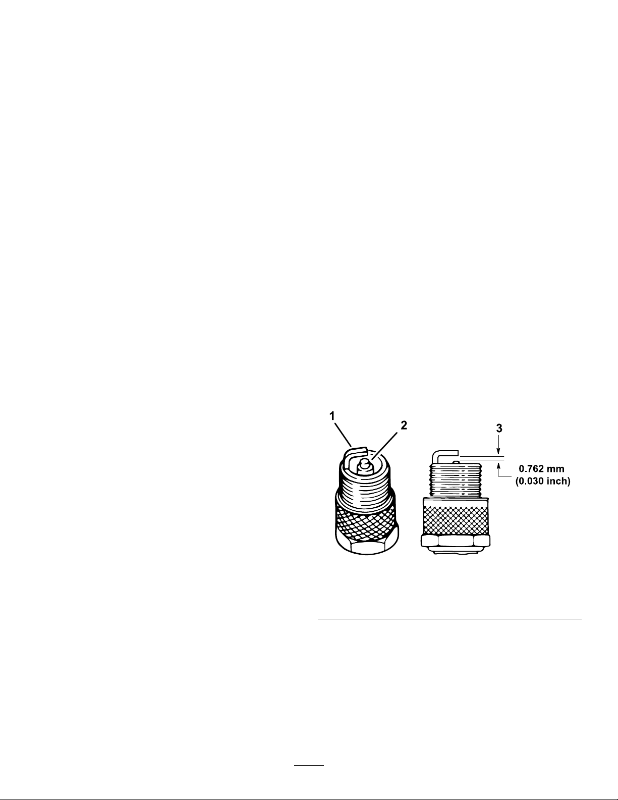
9.Addthespeciedoiltothecrankcaseofthe
engine.
Checkingthe
ServicingtheSparkPlugs
ServiceInterval:Every100hours/Yearly(whichever
comesrst)Replacethesparkplugs
ifnecessary.
Oil-Pressure-Warning
Light
ServiceInterval:Beforeeachuseordaily
Note:Ifyoujustshutofftheengine,itmaytake1to
2minutesforthelighttocomeon.
1.Engagetheparkingbrake.
2.TurnthekeyswitchtotheONposition,butdo
notstarttheengine.
Note:Theoil-pressurelightshouldglowred.
Note:Ifthelightdoesnotfunction,eitherabulb
isburnedout,orthereisamalfunctioninthe
systemthatyoumustrepair.
Type:ChampionRN14YC(orequivalent)
AirGap:0.762mm(0.03inch)
Important:Acracked,fouled,dirty,or
malfunctioningsparkplugmustbereplaced.Do
notsand-blast,scrape,orcleanelectrodesby
usingawirebrushbecausegritmayeventually
releasefromtheplugandfallintothecylinder.
Theresultisusuallyadamagedengine.
Note:Theplugshouldberemovedandchecked
whenevertheenginemalfunctions.
1.Cleantheareaaroundthesparkplugsothat
foreignmattercannotfallintothecylinderwhen
youremovethesparkplug.
2.Pullthewireofftheterminalofthesparkplug.
3.Removetheplugfromthecylinderhead.
4.Checktheconditionofthesideelectrode,center
electrode,andcenterelectrodeinsulatorto
ensurethatthereisnodamage(Figure46).
Note:Donotuseadamagedorwornspark
plug.Replaceitwithanewsparkplugofthe
speciedtype.
Figure46
1.Sideelectrode
2.Centerelectrodeinsulator
5.Settheairgapbetweenthecenterandside
oftheelectrodesat0.762mm(0.030inch)as
showninFigure46.
6.Installthesparkplugintothecylinderhead,and
torquetheplugto20N∙m(14.7ft-lb).
7.Installthespark-plugwire.
8.Repeatsteps1through7fortheotherspark
plug.
43
3.Airgap(nottoscale)
g238425
Page 44
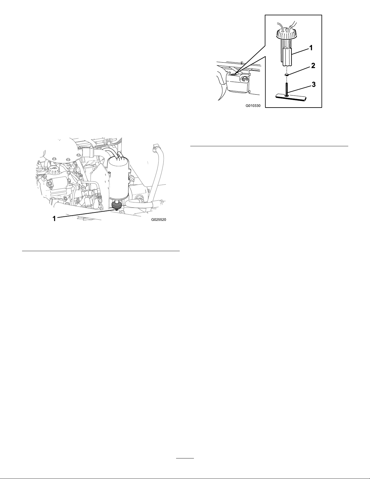
FuelSystem
Maintenance
InspectingtheCarbon
CanisterAirFilter
ServiceInterval:Aftertherst50hours—Inspectthe
openingonthelter.
Every200hours—Changethecarboncanister
airlter.
1.Locatetheairlteronthebottomofthecarbon
canister(Figure47).
Figure47
1.Filteropening
2.Ensurethattheopeningonthebottomofthe
lterisclearandopen.
3.Removeandinstallthenewlter(ifnecessary).
g010330
Figure48
1.Fuelpump
2.Hoseclamp
4.Removethefuel-pumpcapfromthetopofthe
fueltank(Figure48).
3.Fuelline/fuellter
Important:Donotallowthefuel-pump
assemblytorotateinthetankwhileremoving
thefuelpump.Damagetotheoatassembly
canoccurifthefuelpumprotatesinsidethe
fueltank.
5.Removethefuel-pumpassemblyandthefuel
g025520
lterfromthetank(Figure48).
6.Removetheclampsecuringthefuellterhose
tothefuel-pumptting.
7.Removethehosefromthetting(Figure48).
8.Insertthenewhoseclampontothenew
fuel-lterhose.
9.Insertthehoseontothefuelpumpandsecure
theclamp.
ReplacingtheFuelFilter
ServiceInterval:Every400hours
1.Raisethebedandplacethesafetysupporton
theextended-liftcylindertoholdupthebed.
2.Unplugthewire-harnessconnectorsfromthe
fuelpump(Figure48).
3.Loosenthehoseclampanddisconnectthefuel
linefromthefuel-pumpcap(Figure48).
10.Inserttheassemblyintothefueltank,and
tightenthecapto20to22N∙m(175to200in-lb).
11.Connectthewiresandsecurethehosewiththe
hoseclamp.
InspectingFuelLinesand
Connections
ServiceInterval:Every400hours/Yearly(whichever
comesrst)
Inspectthefuellines,ttings,andclampsforsignsof
leaking,deterioration,damage,orlooseconnections.
Note:Repairanydamagedorleakingfuelsystem
componentbeforeusingthemachine.
44
Page 45
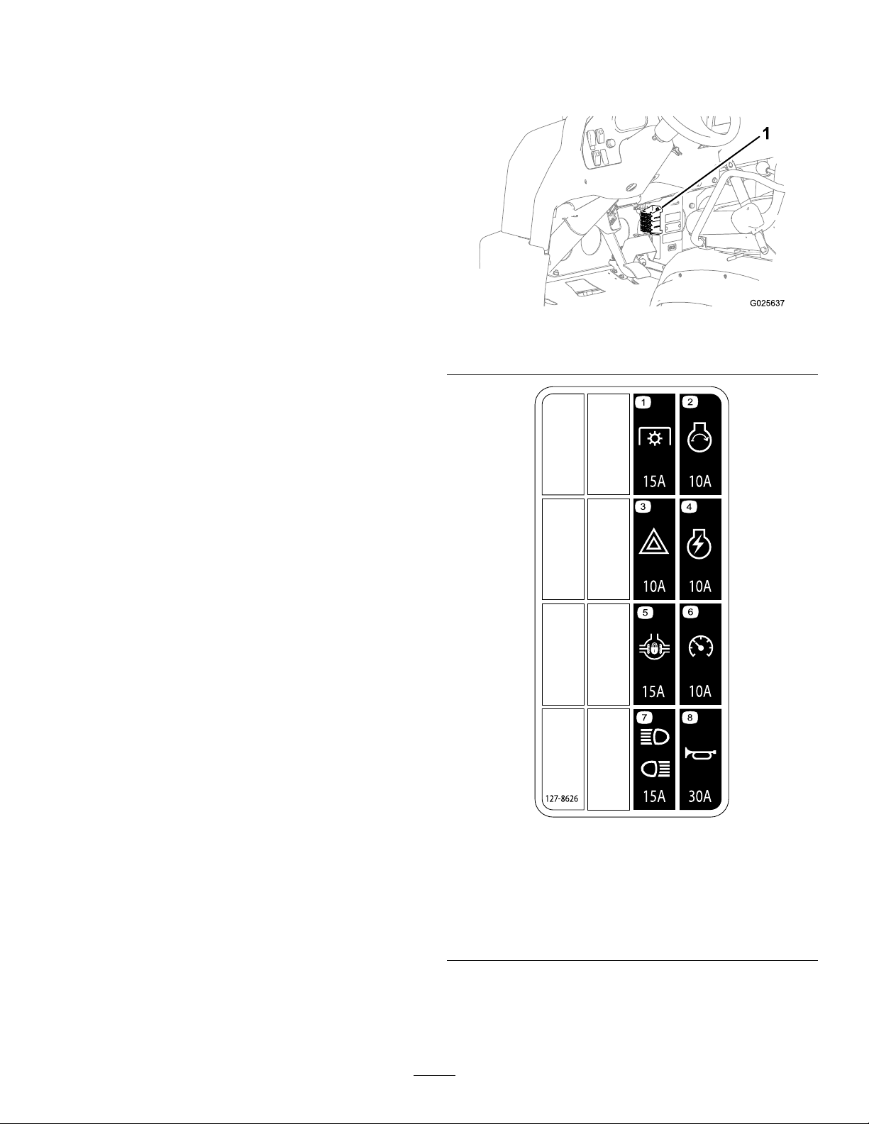
ElectricalSystem
ServicingtheFuses
Maintenance
ElectricalSystemSafety
•Disconnectthebatterybeforerepairingthe
machine.Disconnectthenegativeterminalrst
andthepositivelast.Connectthepositiveterminal
rstandthenegativelast.
•Chargethebatteryinanopen,well-ventilated
area,awayfromsparksandames.Unplugthe
chargerbeforeconnectingordisconnectingthe
battery.Wearprotectiveclothinganduseinsulated
tools.
Thefusesfortheelectricalsystemarelocatedunder
thecenterofthedashpanel(Figure49andFigure50).
g025637
Figure49
1.Fuses
Figure50
1.Powertakeoff(15A)5.Differentiallock(15A)
2.Enginestart(10A)6.Speedometer(10A)
3.Hazards(10A)
4.Engineignition(10A)8.Horn(30A)
45
7.Headlightsandrearlights
(15A)
decal127-8626a
Page 46
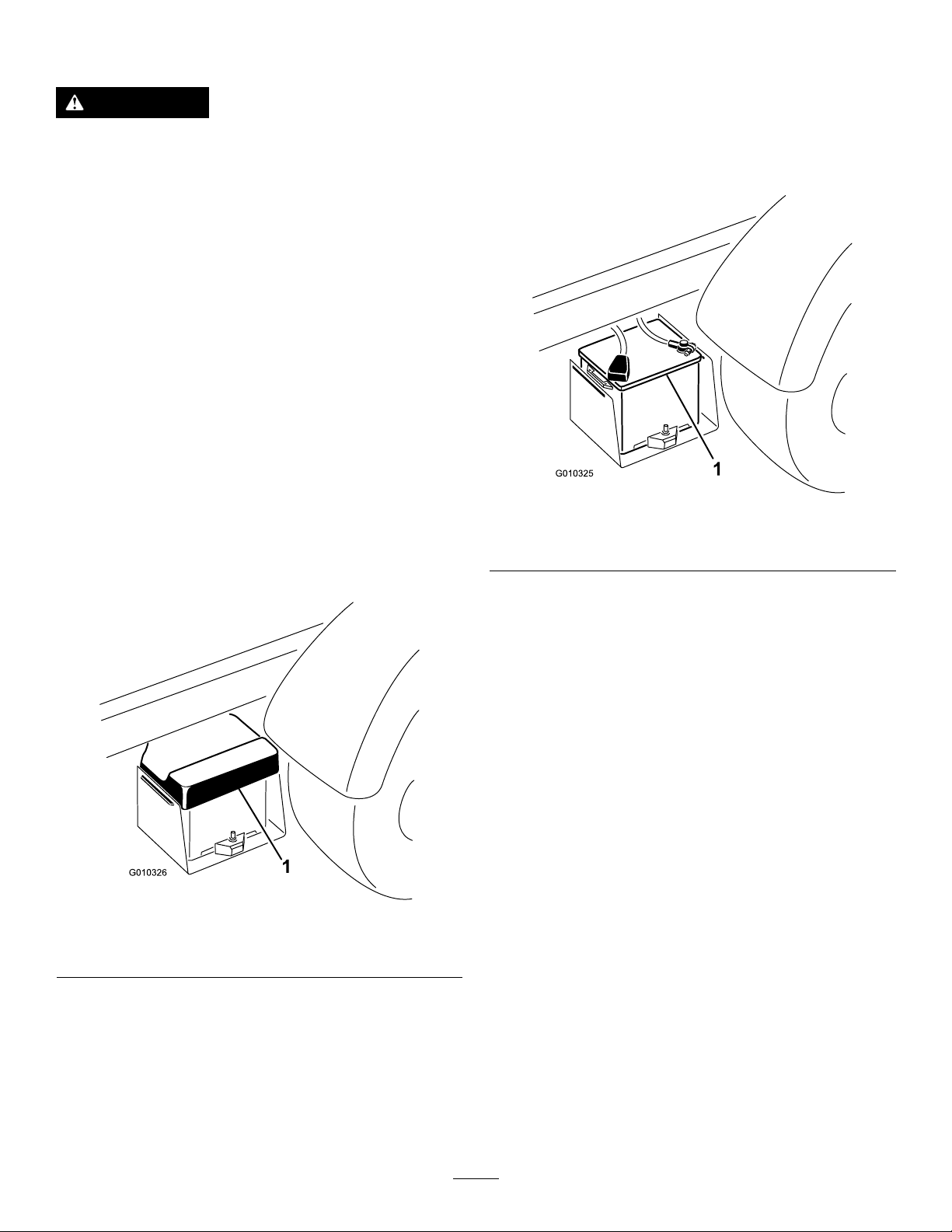
Jump-StartingtheMachine
Note:Thenegativeterminalhas“NEG”onthe
batterycover.
WARNING
Jump-startingcanbedangerous.T oavoid
personalinjuryordamagetoelectrical
componentsinmachine,observethe
followingwarnings:
•Neverjump-startwithavoltagesource
greaterthan15VDC;thisdamagesthe
electricalsystem.
•Neverattempttojump-startadischarged
batterythatisfrozen.Itcouldruptureor
explodeduringjump-starting.
•Observeallbatterywarningswhile
jump-startingyourmachine.
•Besureyourmachineisnottouchingthe
jump-startmachine.
•Connectingcablestothewrongpostcould
resultinpersonalinjuryand/ordamageto
theelectricalsystem.
1.Squeezethebatterycovertoreleasethetabs
fromthebatterybaseandremovethebattery
coverfromthebatterybase(Figure51).
Note:Donotconnecttheotherendofthe
jumpercabletothenegativepostofthe
dischargedbattery.Connectthejumpercableto
theengineorframe.Donotconnectthejumper
cabletothefuelsystem.
g010325
Figure52
1.Battery
4.Starttheengineinthemachineprovidingthe
jump-start.
Figure51
1.Batterycover
2.Connectajumpercablebetweenthepositive
postsofthe2batteries(Figure52).
Note:Thepositivepostmaybeidentiedbya
+signontopofthebatterycover.
Note:Letitrunforafewminutes,thenstart
yourengine.
5.Removethenegativejumpercablerstfrom
yourengine,thenthebatteryintheother
machine.
6.Installthebatterycovertothebatterybase.
g010326
3.Connect1endoftheotherjumpercabletothe
negativeterminalofthebatteryintheother
machine.
46
Page 47
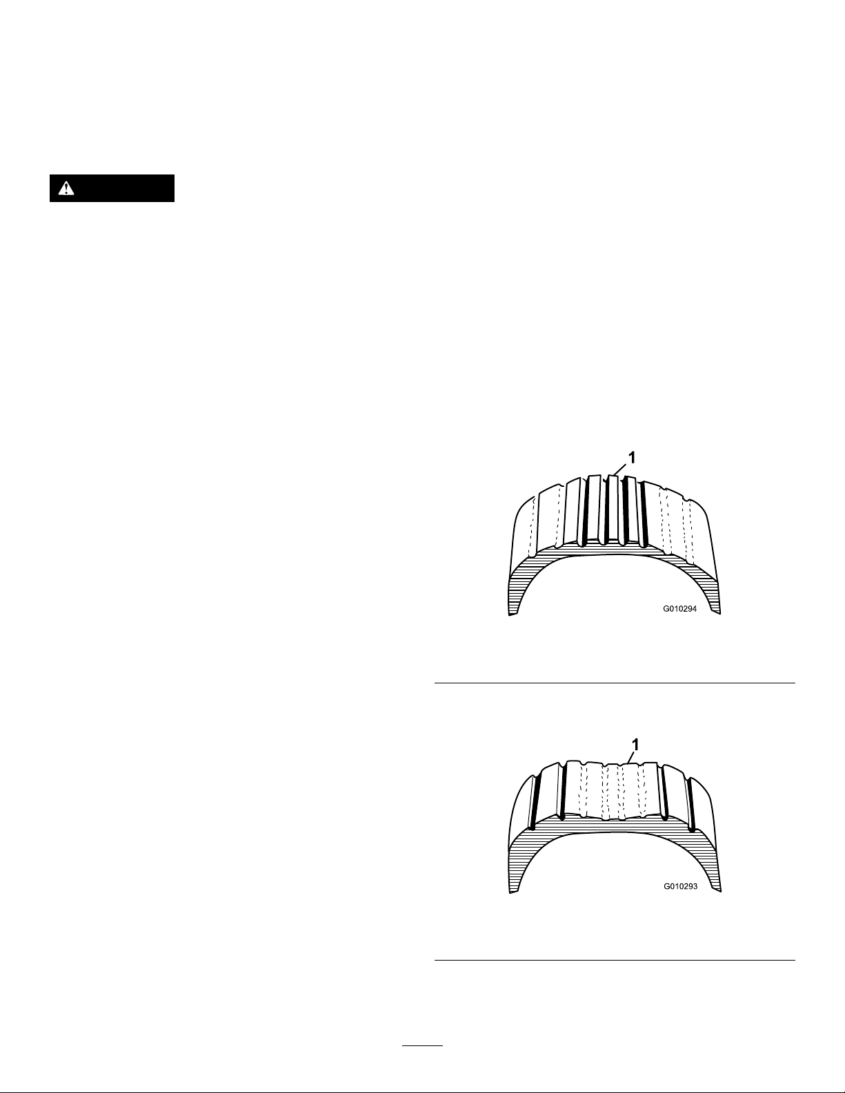
ServicingtheBattery
DriveSystem
ServiceInterval:Every50hours—Checkthe
battery-uidlevel(every30daysif
instorage).
Every50hours—Checkthebatterycable
connections.
DANGER
Batteryelectrolytecontainssulfuricacid,
whichisfatalifconsumedandcausessevere
burns.
•Donotdrinkelectrolyteorallowitto
contactyourskin,eyesorclothing.Wear
safetyglassestoshieldyoureyesand
rubberglovestoprotectyourhands.
•Fillthebatterywherecleanwaterisalways
availableforushingtheskin.
•Alwayskeepthebatterycleanandfullycharged.
•Ifthebatteryterminalsarecorroded,cleanthem
withasolutionof4partswaterand1partbaking
soda.
Maintenance
InspectingtheTires
ServiceInterval:Every100hours
Fronttiresairpressurespecication:220kPa(32
psi)
Reartiresairpressurespecication:124kPa(18
psi)
Operatingaccidents,suchashittingcurbs,can
damageatireorrimandalsodisruptwheelalignment,
soinspectthetireconditionafteranaccident.
Important:Checkthetirepressurefrequently
toensureproperination.Ifthetiresarenot
inatedtothecorrectpressure,thetireswillwear
prematurelyandmaycause4-wheeldrivetobind.
Figure53isanexampleoftirewearcausedby
under-ination.
•Applyalightcoatingofgreasetothebattery
terminalstopreventcorrosion.
•Maintainthebatteryelectrolytelevel.
•Keepthetopofthebatterycleanbywashingit
periodicallywithabrushdippedinammoniaor
bicarbonateofsodasolution.Flushthetopsurface
withwateraftercleaning.Donotremovethell
capwhilecleaning.
•Ensurethatthebatterycablesarekepttightonthe
terminalstoprovidegoodelectricalcontact.
•Maintainthecellelectrolytelevelwithdistilledor
demineralizedwater.Donotllthecellsabovethe
bottomofthellringinsideeachcell.
•Ifyoustorethemachineinalocationwhere
temperaturesareextremelyhigh,thebatteryruns
downmorerapidlythanifthemachineisstoredin
alocationwheretemperaturesarecool.
g010294
Figure53
1.Under-inatedtire
Figure54isanexampleoftirewearcausedby
over-ination.
1.Over-inatedtire
47
g010293
Figure54
Page 48
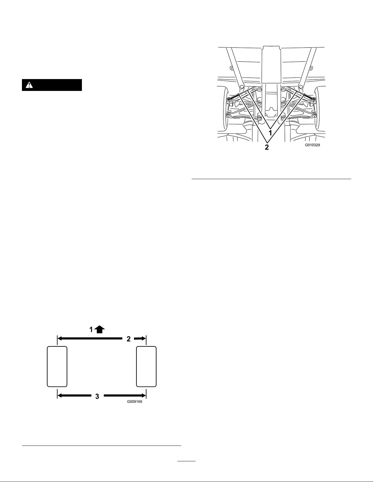
CheckingtheTorqueofthe
WheelNuts
ServiceInterval:Aftertherst2hours
Aftertherst10hours
Every200hours
WARNING
Failuretomaintainpropertorqueofthewheel
nutscouldresultinfailureorlossofawheel
andmayresultinpersonalinjury.
Torquethefrontandrearwheelnutsto109
to122N∙m(80to90ft-lb)after1to4hours
ofoperationandagainafter10hoursof
operation.Torquethewheelnutsevery200
hoursthereafter.
CheckingtheFrontWheel
Alignment
ServiceInterval:Every400hours/Yearly(whichever
comesrst)
1.Ensurethatthetiresarefacingstraightahead.
2.Measurethecenter-to-centerdistance(ataxle
height)atthefrontandrearofthesteeringtires
(Figure55).
Note:Themeasurementmustbewithin0±3
mm(0±0.12inch)atthefrontofthetirethenat
therearofthetire.Rotatethetire90°andcheck
themeasurement.
3.Adjustthecenter-to-centerdistanceasfollows:
A.Loosenthejamnutatthecenterofthetie
rod(Figure56).
g010329
Figure56
1.Tierods2.Jamnuts
B.Rotatethetierodtomovethefrontofthe
tireinwardoroutwardtoachievethecenter
tocenterdistancesfromfronttoback.
C.Tightenthetierodjamnutwhenthe
adjustmentiscorrect.
D.Checktoensurethatthetiresturnanequal
amounttotherightandtotheleft.
Note:Ifthetiresdonotturnequally,refer
totheServiceManualfortheadjustment
procedure.
Important:Checkthemeasurementsat
consistentlocationsonthetire.Themachine
shouldbeonaatsurfacewiththetires
facingstraightahead.
Figure55
1.Frontofthemachine3.Centertocenterdistance
2.0±3mm(0±0.12inch)
fronttorearofthetire
g009169
48
Page 49
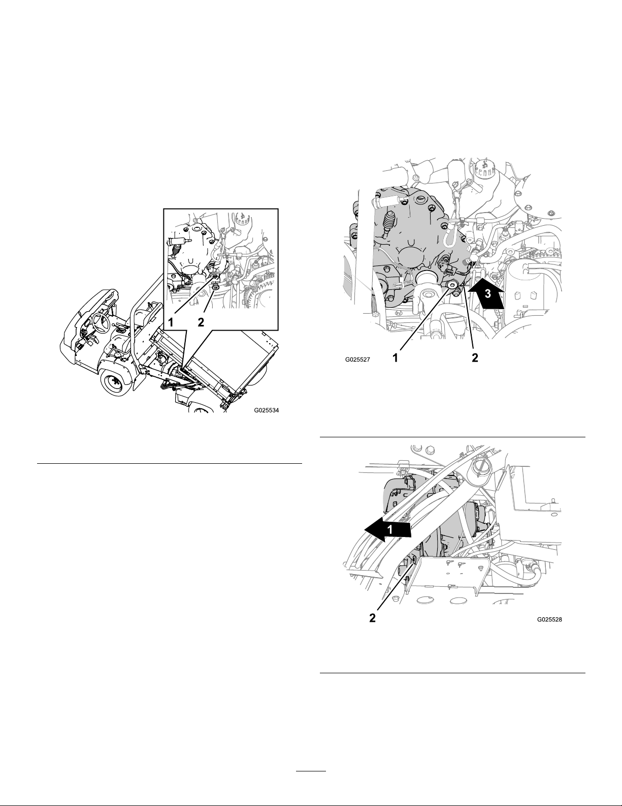
Maintainingthe
Transmission
ChangingtheTransmissionFluid
Transmission-uidtype:DexronVI
Transmission-uidcapacity:700ml(23.7oz)
CheckingtheTransmission-Fluid
Level
ServiceInterval:Aftertherst50hours
Every400hours
Transmission-uidtype:DexronVI
1.Locatethellplugattheatthelower-inboard
areaatthebackofthetransmission(Figure57).
1.Parkthemachinetoalevelsurface.
2.Locatethellplugatthebackinboardarea
ofthetransmissioncaseandthelocatethe
drainplugatthefrontoutboardsideofthe
transmission(Figure58andFigure59).
g025527
Figure58
Figure57
1.Fillport(transmission)
2.Alignadrainpanbelowthellplug.
3.Rotatetheplugcounterclockwiseandremove
theplugfromthellportinthetransmission
(Figure57).
2.Fillplug
Note:Whenthetransmissionuidlevelis
correct,theuidshouldbelevelwiththebottom
ofthethreadsinthellport.
4.Ifthetransmission-uidlevelislow,add
transmissionuidofthespeciedtypeintothe
transmissionthroughthellportuntiltheuid
levelisushwiththebottomofthethreadsin
theport(Figure57).
Note:Useafunnelwithaexiblehosewhen
llingthetransmission.
5.ChecktheconditionoftheO-ringatthellplug.
Note:ReplacetheO-ringifitiswarnor
damaged.
1.Fillplug3.Forward
g025534
2.Transmissioncase(back
inboardlocation)
g025528
Figure59
1.Forward2.Drainplug
3.Removethellplugfromthellportbyrotating
theplugcounterclockwiseandremovingitfrom
thetransmission(Figure58).
6.Installthellplugintothetransmissionand
tightenitbyhand(Figure57).
4.Alignadrainpanbelowthedrainplug(Figure
59).
49
Page 50
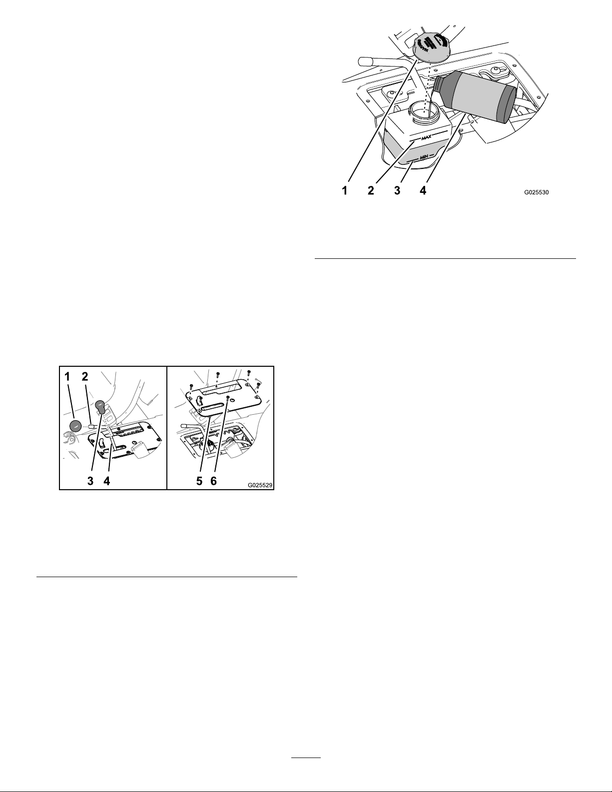
5.Removethedrainplugfromthedrainportby
rotatingtheplugcounterclockwiseandremoving
itfromthetransmission(Figure59).
Note:Allowthetransmissionuidtodrain
completely.
6.Installthedrainplug(Figure59).
7.Add700ml(23.7oz)ofDexronVItransmission
uidintothetransmissionthroughthellport
(Figure58).
Note:Useafunnelwithaexiblehosewhen
llingthetransmission.
Note:Whenthetransmissionuidlevelis
correct,theuidshouldbelevelwiththebottom
ofthethreadsinthellport.
8.Installthellplug(Figure58).
ServicingtheReservoirofthe
Speed-ControlCylinder
ServiceInterval:Every200hours
Reservoir-uidtype:DOT3brakeuid
1.Removetheknobsfromthehydraulic-liftlever
andthespeed-rangelever(Figure60).
Figure60
g025530
Figure61
1.Cap3.Minmark(reservoir)
2.Maxmark(reservoir)4.DOT3brakeuid
5.Iftheuidlevelislow,performthefollowing:
A.Wipecleantheareaaroundthecapforthe
reservoir(Figure61).
B.Removethecapfromthereservoir(Figure
61).
C.Addthespecieduidtoraisethelevel
midwaybetweentheMinandMaxmarkson
thesideofthereservoir(Figure61).
D.Installthecaphandtight(Figure61).
6.Aligntheholesinthecontrol-coverplatetothe
holesintheseatbase(Figure60).
7.Securetheplatetothebasewiththe6
hex-washerscrews(Figure60)thatyou
removedinstep2.
8.Threadtheknobsontotherodsforthe
hydraulic-liftleverandthespeed-rangelever
g025529
(Figure60).
1.Knob(speed-rangelever)4.Rod(hydraulic-liftlever)
2.Rod(speed-rangelever)5.Control-coverplate
3.Knob(hydraulic-liftlever)6.Hex-washerscrews(#10
x3/4inch)
2.Removethe6hex-washerscrews(#10x3/4
inch)thatsecurethecontrol-coverplatetothe
seatbase,andremovethecoverplate(Figure
60).
3.Movethespeed-rangelevertotheTRANSPORT
position;refertoUsingtheSpeed-Range
Control(page27).
4.Checktheuidlevelinthereservoirforthe
speed-controlcylinder(Figure61).
Note:ThenormaluidlevelisbetweentheMin
andMaxmarksonthesideofthereservoir.
AdjustingtheSpeedControl
Important:Theminimumcontrolledspeedfor
themachineis4.0kph(2.5mph)atfullengine
speed.Controllingthemachinespeedslowerthat
4.0kph(2.5mph)resultsinexcessivebeltand
clutchwear.
1.DrivethemachineinspeedrangeA(lowrange),
B(mid-lowrange),C(mid-highrange),orD
(highrange)inordertodeterminewhichspeed
rangeincludesthemaximumgroundspeedthat
youwanttoset;refertoUsingtheSpeed-Range
Control(page27).
Note:Usethespeedometertodeterminethe
speedthatthemachineistraveling.
2.Removetheknobsfromthehydraulic-liftlever
andthespeed-rangelever(Figure60).
50
Page 51
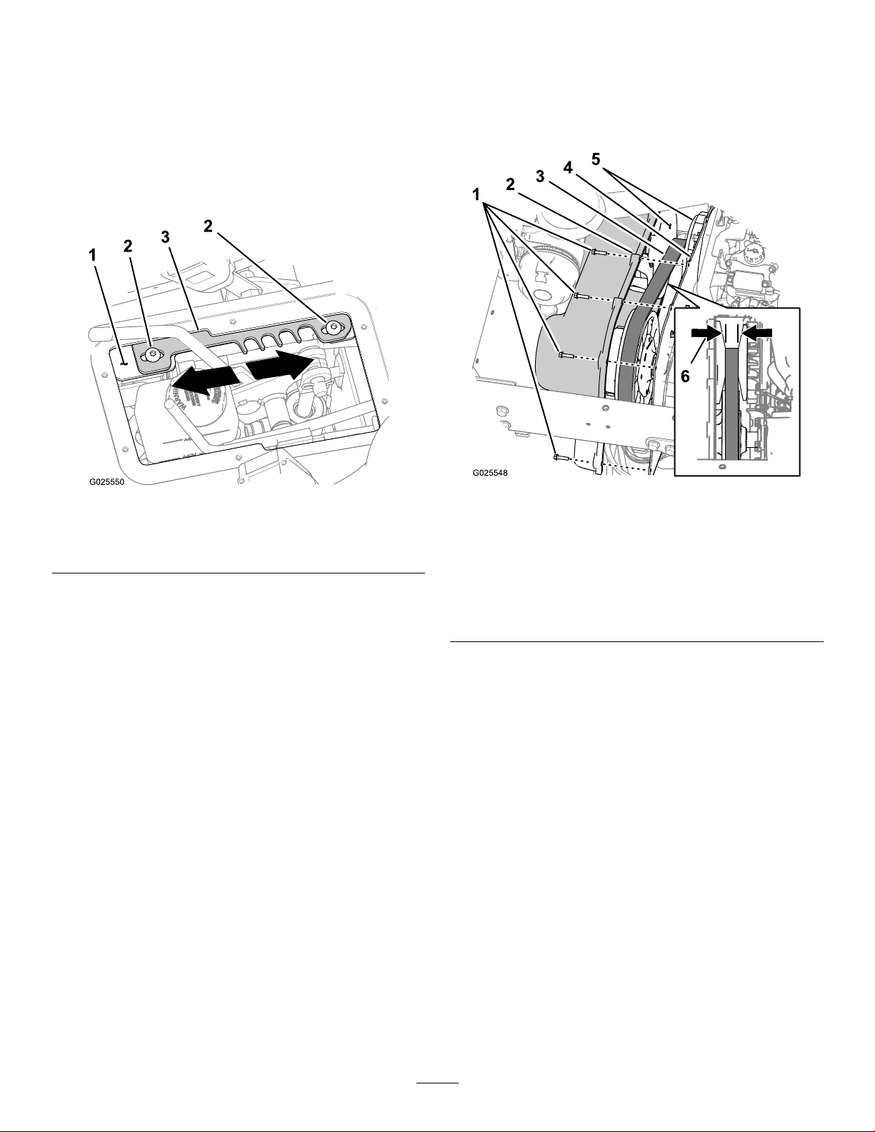
3.Removethe6hex-washerscrews(#10x3/4
inch)thatsecurethecontrol-coverplatetothe
seatbase,andremovethecoverplate(Figure
60).
4.Movethespeed-rangelevertotheT
(TRANSPORT)position(Figure62).
5.Loosenthe2hex-socketscrews(5/16x3/4inch)
thatsecurethedetentplatetothelever-support
bracket(Figure62).
CheckingtheDriveBelt
ServiceInterval:Every400hours
1.Removethe9hex-washerbolts(1/4x1inch)
thatsecurethetransmissioncovertothe
mountingplateofthetransmission(Figure63).
Figure62
1.Lever-supportbracket3.Detentplate
2.Hex-socketscrews
6.Movethedetentplateinoneofthefollowing
directions:
•Movethedetentplateforwardtoincrease
themaximumgroundspeedlimit(Figure62).
•Movethedetentplaterearwardtodecrease
themaximumgroundspeedlimit(Figure62).
7.Tightenthe2hex-socketscrews(5/16x3/4
inch)to19.8to25.4N∙m(14.6to18.7ft-lb).
8.Drivethemachinewiththespeedcontrolset
tospeedrangeforwhichyouaresettingthe
maximumgroundspeedlimit.Ifthemaximum
groundspeedlimitistoofastortooslow,repeat
steps1through8untilthecorrectmaximum
groundspeedlimitisattained.
9.Aligntheholesinthecontrol-coverplatetothe
holesintheseatbase(Figure60).
10.Securetheplatetothebasewiththe6
hex-washerscrews(Figure60)thatyou
removedinstep3.
11.Threadtheknobsontotherodsforthe
hydraulic-liftleverandthespeed-rangelever
(Figure60).
g025550
1.Hex-washerbolts(1/4x1
inch)
2.Transmissioncover
3.Drivebelt6.Beltwidth—replaceat
Figure63
4.Mountingplate
5.Taperedfaces(primary
clutch)
29.5mm(1.16inches)or
less
g025548
2.Movethecoverforwarduntilyoucanseethe
drivebelt(Figure63).
3.Checkthetaperedfacesoftheprimaryclutch
forsignsifdamage(Figure63).
Note:Ifthefacesoftheprimaryclutchare
damaged,replacetheprimaryclutch;contact
yourAuthorizedServiceDealer.
4.Checkthedrivebeltformissingordamaged
cogs(Figure63).
Note:Ifthecogsofthedrivebeltaremissingor
damaged,replacethedrivebelt.
5.Measureacrossthebeltandrecordthebelt
width(Figure63).
Note:Ifthewidthofthebeltis29.5mm(1.16
inches)orless,replacethebelt(Figure63).
6.Aligntheholesinthetransmissioncoverwith
theholesinthemountingplate(Figure63).
7.Securethecovertothemountingplate(Figure
63)withthe9hex-washerbolts(1/4x1inch)
51
Page 52
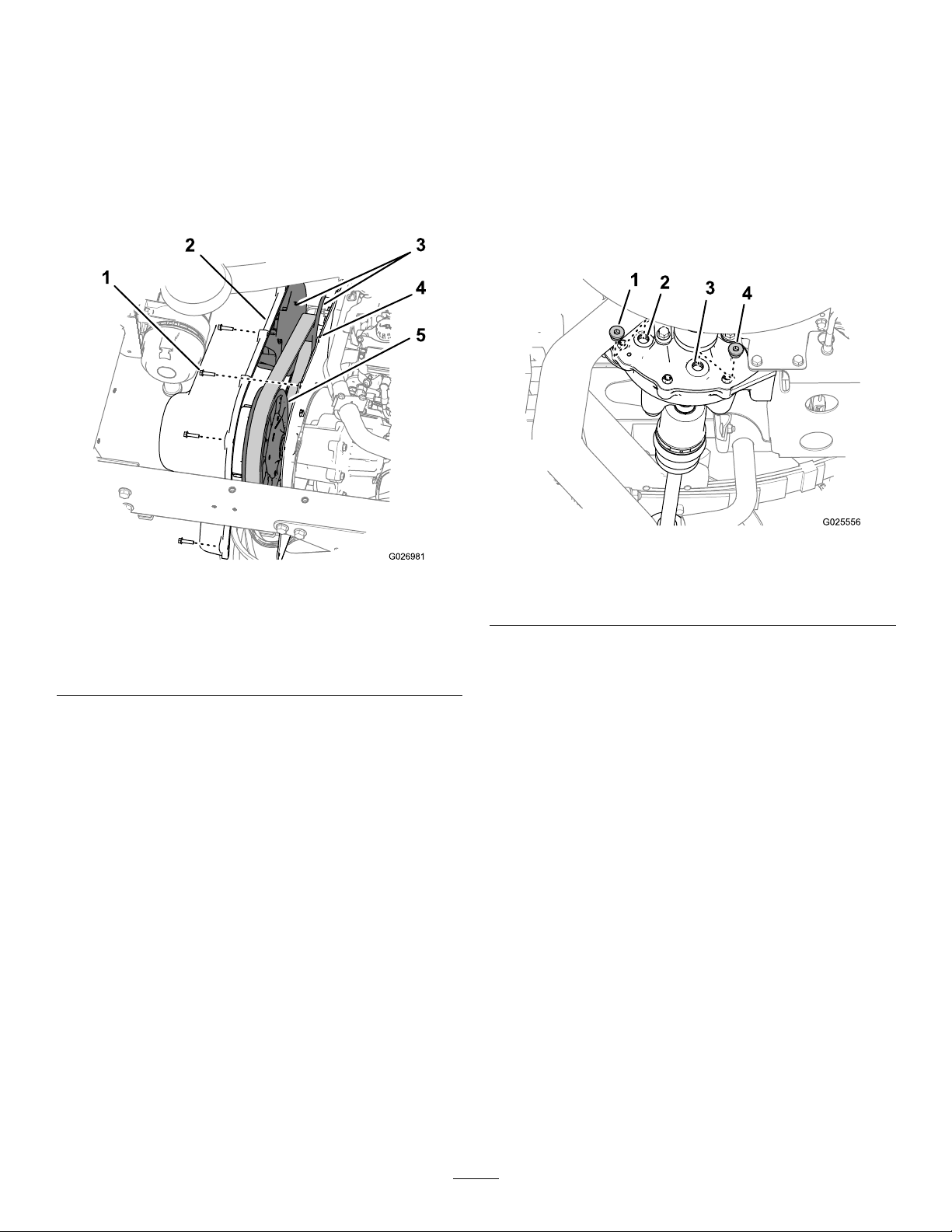
thatyouremovedinstep1,andtorquethebolts
to10.2to12.4N∙m(90to110in-lb).
CleaningtheClutches
ServiceInterval:Every400hours
1.Removethe9hex-washerbolts(1/4x1inch)
thatsecurethetransmissioncovertothe
mountingplateofthetransmission(Figure64).
MaintainingtheDifferential
andAxles
ChangingtheDifferentialOil
Oiltype:80W90APIGL-5
Oilcapacity:550ml(18.6oz)
1.Alignadrainpanunderthedrainplug(Figure
65).
Figure64
1.Hex-washerbolts(1/4x1
inch)
2.Transmissioncover
3.Primaryclutch
2.Attheprimaryandsecondaryclutches,Remove
dirtandmudbuildupwithwateranddry
immediatelywithcompressedairtoremove
excesswateranddebris.
3.Removeanyremainingdebrisusingafast-drying
contactcleanerorbrakecleaner.
4.Mountingplate
5.Secondaryclutch
Note:Note:Removethedebrisinandaround
movingparts.
4.Ifdebrisorbuildupexistsaroundthebeltor
alongtheclutchshaft,useaneabrasivepad
orasimilarproducttoremoveit.
5.Aligntheholesinthetransmissioncoverwith
theholesinthemountingplate(Figure64).
6.Securethecovertothemountingplate(Figure
64)withthe9hex-washerbolts(1/4x1inch)
thatyouremovedinstep1,andtorquethebolts
to10.2to12.4N∙m(90to110in-lb).
g025556
Figure65
g026981
1.Fillplug3.Drainport
2.Fillport4.Drainplug
2.Removethellplugfromthellportandthe
drainplugfromthedrainportofthedifferential
(Figure65).
Note:Allowthedifferentialtocompletelydrain.
3.ChecktheconditionoftheO-ringsontheplugs.
Note:ReplacedamagedorwornO-rings.
4.Installthedrainplugintothedrainport(Figure
65),andtighttheplugto14to19N∙m(10to14
ft-lb).
Note:Thedrainplugismagnetic.Itisnormal
toseesmallamountsofferrous-metalparticles
aroundmagnet—expectmoreparticlesaround
themagnetaftertheinitialbreak-in.
5.Add550ml(18.6oz)ofthespeciedoilinto
thellportofthedifferential(Figure65).
Note:Useafunnelwithaexiblehosetoadd
oiltothedifferential.
6.Installthellplugintothellport(Figure65),
andtightentheplugto14to19N∙m(10to14
ft-lb).
52
Page 53
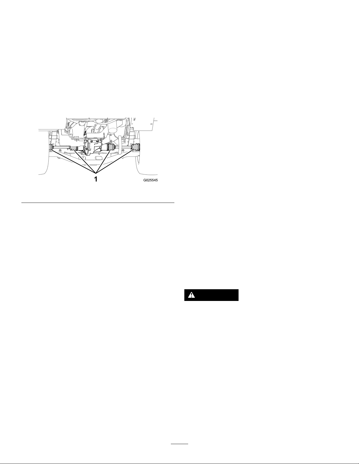
CheckingtheConstant-Velocity
Boots
ServiceInterval:Every100hours
CoolingSystem
Maintenance
1.Jackupthebackendofthemachineand
supportitwithjackstands;refertoRaisingthe
Machine(page37).
2.ChecktheCV(constantvelocity)bootsatthe
rearaxlesfordamageandleakinglubricant
(Figure66).
Note:ReplaceanydamagedorleakingCV
bootbeforeoperatingthemachine.
Figure66
3.Removethejackstandsandlowerthemachine
totheground.
CoolingSystemSafety
•Swallowingenginecoolantcancausepoisoning;
keepoutofreachfromchildrenandpets.
•Dischargeofhot,pressurizedcoolantortouching
ahotradiatorandsurroundingpartscancause
severeburns.
–Alwaysallowtheenginetocoolatleast15
minutesbeforeremovingtheradiatorcap.
–Usearagwhenopeningtheradiatorcap,and
openthecapslowlytoallowsteamtoescape.
•Donotoperatethemachinewithoutthecovers
inplace.
•Keepyourngers,handsandclothingclearof
rotatingfananddrivebelt.
•Shutofftheengineandremovethekeybefore
performingmaintenance.
g025545
Checkingthe
Engine-CoolantLevel
ServiceInterval:Beforeeachuseordaily—Check
thelevelofthecoolant.Check
theCoolantlevelattheoverow
reservoironly.Donotremovethe
radiatorcap.(Checkthecoolant
levelbeforetheengineisrst
startedanddailythereafter.)
Coolanttype:a50/50solutionofwaterand
permanentethylene-glycolantifreeze
CAUTION
Iftheenginehasbeenrunning,the
pressurized,hotcoolantcanescapeand
causeburns.
•Donotopentheradiatorcap.
•Allowtheenginetocoolforatleast15
minutesoruntiltheradiatorcapiscool
enoughtotouchwithoutburningyour
hand.
•Usearagwhenopeningthereserve-tank
cap,andopenthecapslowlytoallow
steamtoescape.
•Donotcheckthecoolantlevelatthe
radiator;checkthecoolantlevelatthe
reservetankonly.
1.Parkthemachineonalevelsurface.
53
Page 54
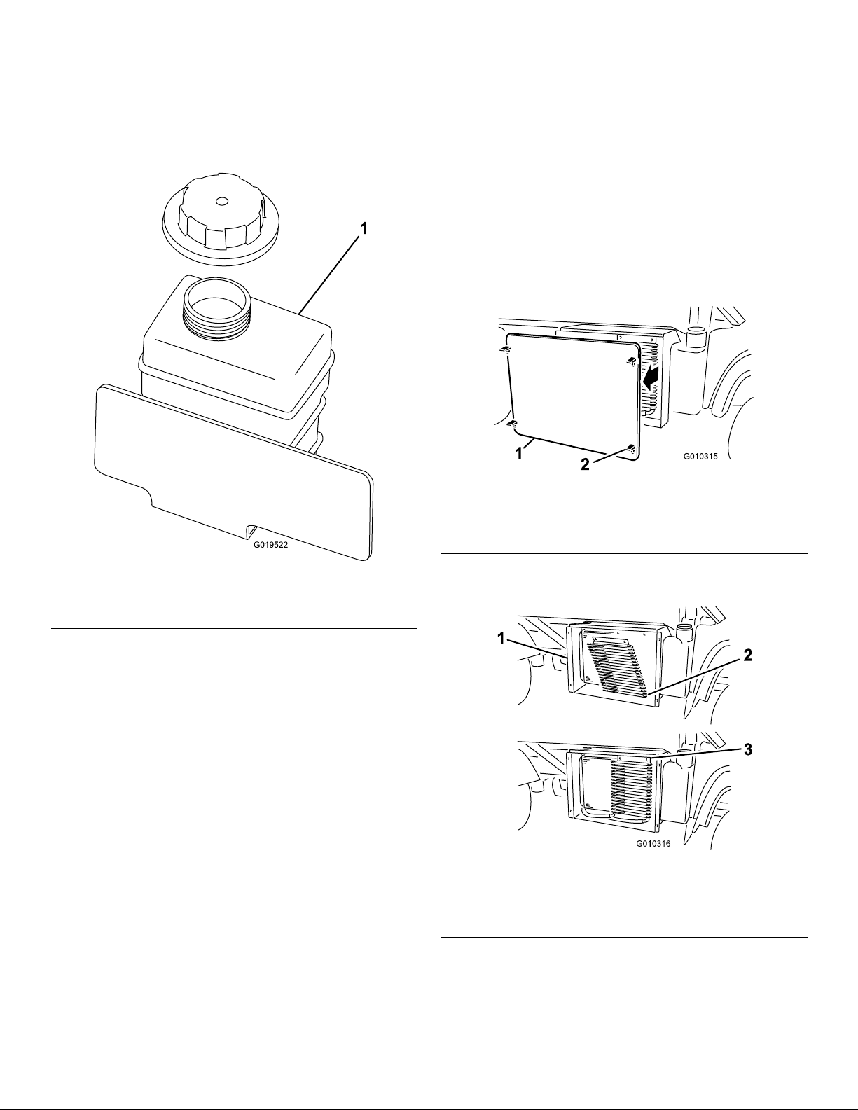
2.Engagetheparkingbrake.
3.Shutofftheengineandremovethekey.
4.Checkthecoolantlevelatthereservetank
(Figure67).
Note:Thecoolantshouldbeuptothebottom
ofthellerneck.
RemovingDebrisfromthe
CoolingSystem
ServiceInterval:Beforeeachuseordaily—Remove
debrisfromtheengineareaand
radiator.(Cleanitmorefrequentlyin
dirtyconditions.)
1.Parkthemachineonalevelsurface.
2.Engagetheparkingbrake.
3.Shutofftheengineandremovethekey.
4.Cleantheengineareathoroughlyofalldebris.
5.Unlatchandremovetheradiatorscreenfromthe
frontoftheradiator(Figure68).
Figure67
1.Coolant-reservetank
5.Ifcoolantislow,removethereserve-tankcap
andadda50/50mixtureofwaterandpermanent
ethylene-glycolantifreeze.
Note:Donotoverll.
6.Installthereserve-tankcap.
g010315
Figure68
1.Radiatorscreen
2.Latch
g019522
6.Ifequipped,rotatethelatchesandpivottheoil
coolerawayfromtheradiator(Figure69).
g010316
Figure69
1.Radiatorhousing3.Latches
2.Oilcooler
7.Cleantheradiator,oilcooler,andscreenwith
compressedair.
Note:Blowdebrisawayfromtheradiator.
8.Installthecoolerandscreentotheradiator.
54
Page 55
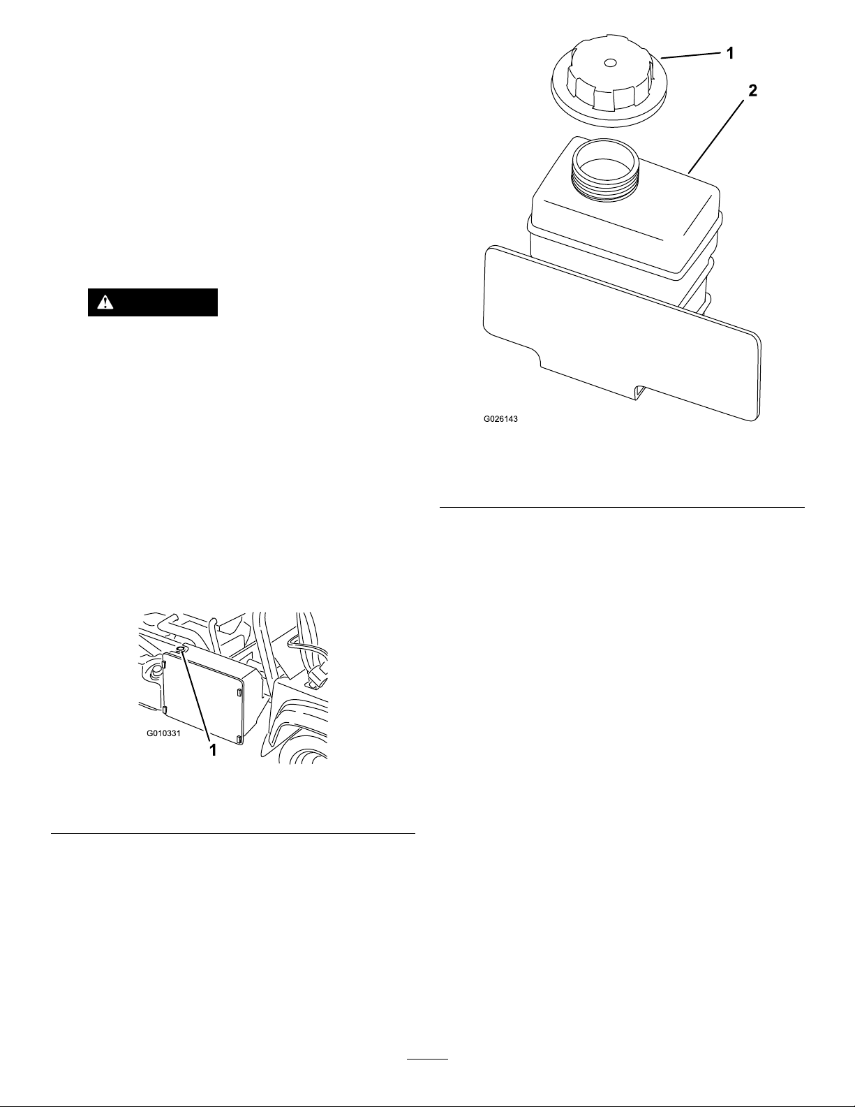
ChangingtheEngine
Coolant
ServiceInterval:Every1,000hours/Every2years
(whichevercomesrst)
Cooling-systemcapacity:3.7L(4USqt)
Coolanttype:a50/50solutionofwaterand
permanentethylene-glycolantifreeze
1.Parkthemachineonalevelsurface.
2.Raisethebedandinstallthebedsafetysupport
ontheextendedliftcylindertosecurethebed.
CAUTION
Iftheenginehasbeenrunning,the
coolingsystempressurizeswithhot
coolantthatcanescapeandcauseburns.
•Donotopentheradiatorcapwhenthe
engineisrunning.
•Allowtheenginetocoolforatleast
15minutesoruntiltheradiatorcapis
coolenoughtotouchwithoutburning
yourhand.
g026143
Figure71
1.Reservetank-cap
2.Reservetank
•Usearagtoopentheradiatorcap.
Openthecapslowlytoallowthe
steamtoescape.
3.Removetheradiatorcap(Figure70).
Figure70
1.Radiatorcap
4.Removethereserve-tankcap(Figure70).
5.Disconnectthelowerradiatorhoseandallow
thecoolanttoowintoadrainpan.
Note:Whenthecoolantstopsowing,connect
thelowerradiatorhose.
6.Slowlylltheradiatorwitha50/50mixtureof
waterandpermanentethylene-glycolantifreeze
7.T opofftheradiatorandinstallthecap(Figure
70).
8.Slowlyllthecoolant-reservetankuntillevel
reachesthebottomofthellerneck(Figure71).
9.Installthereserve-tankcap(Figure71).
g010331
10.Starttheengineandoperateituntilitiswarm.
11.Shutofftheengine,checkthecoolantlevel,and
replenishthecoolant,ifnecessary.
55
Page 56
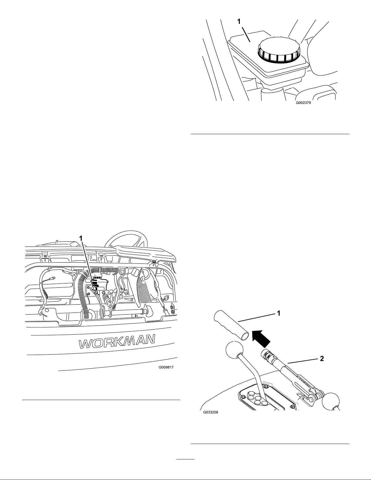
BrakeMaintenance
CheckingtheBrake-Fluid
Level
ServiceInterval:Beforeeachuseordaily—Check
thebrake-uidlevel.(Checkthe
levelbeforetheengineisrst
startedanddailythereafter.)
Every1,000hours/Every2years(whichever
comesrst)—Changethebrakeuid.
Brake-uidtype:DOT3brakeuid
Note:Thebrake-uidreservoirshipsfromthefactory
lledwithDOT3brakeuid.
1.Parkthemachineonalevelsurface.
2.Engagetheparkingbrake.
3.Shutofftheengineandremovethekey.
4.Removethehood.
5.Checktheuidlevelinthebrake-uidreservoir
(Figure72andFigure73).
Note:TheuidlevelshouldbeuptotheFull
lineonthereservoir.
g002379
Figure73
1.Brake-uidreservoir
6.Iftheuidlevelislow,performthefollowing:
A.Cleantheareaaroundthecapforthe
reservoir(Figure73).
B.Removethereservoircap(Figure73).
C.AddthespeciedbrakeuidtotheFullline
onthereservoir(Figure73).
Important:Donotoverllthebrake-uid
reservoir.
D.Installthecap(Figure73).
7.Installthehood.
AdjustingtheParking
Brake
ServiceInterval:Aftertherst10hours
Every200hours
1.Brake-uidreservoir
Figure72
1.Removetherubbergripfromtheparking-brake
lever(Figure74).
g009817
g033258
Figure74
1.Grip
56
2.Parking-brakelever
Page 57
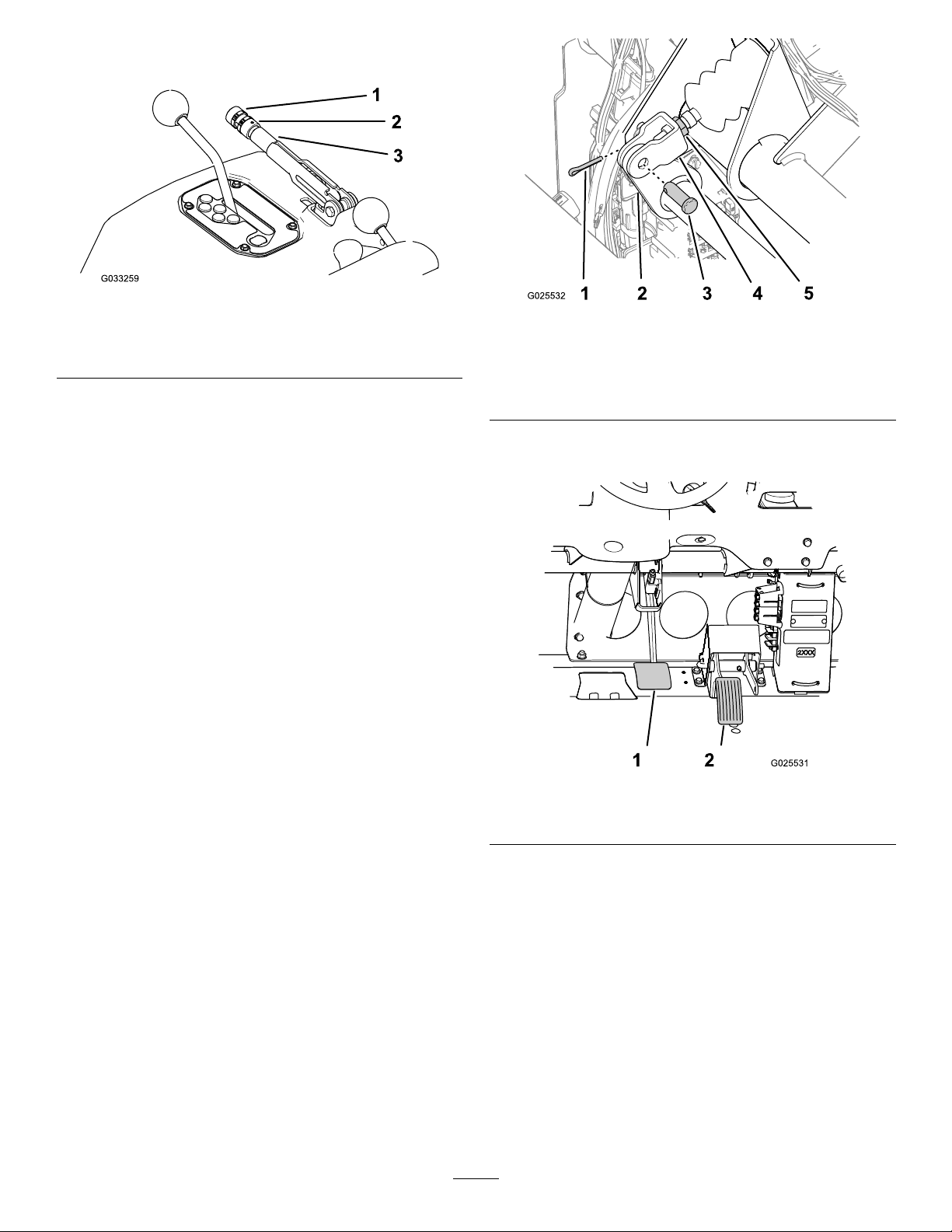
2.Loosenthesetscrewsecuringtheknobtothe
parking-brakelever(Figure75).
Figure75
1.Knob3.Parking-brakelever
2.Setscrew
3.Rotatetheknob(Figure75)untilaforceof20
to22kg(45to50lb)isrequiredtoactuatethe
lever.
4.Tightenthesetscrewwhennished(Figure75).
Note:Ifyoucannolongermakeaparking-brake
adjustmentbyadjustingtheparking-brake
lever,loosenthehandletothemiddleofthe
adjustmentandadjustthecableattherear,then
repeatstep3.
g033259
g025532
Figure76
1.Cotterpin
2.Brake-pedalpivot5.Jamnut
3.Clevispin
4.Mastercylinderyoke
3.Liftuponthebrakepedal(Figure77)untilit
contactstheframe.
5.Installtherubbergripontotheparking-brake
lever(Figure74).
AdjustingtheBrakePedal
ServiceInterval:Every200hours
1.Removethehood.
2.Removethecotterpinandclevispinsecuring
themastercylinderyoketothebrake-pedal
pivot(Figure76).
g025531
Figure77
1.Brakepedal2.Acceleratorpedal
4.Loosenthejamnutssecuringtheyoketothe
mastercylindershaft(Figure76).
5.Adjusttheyokeuntilitsholesalignwiththehole
inthebrake-pedalpivot(Figure76).
6.Securetheyoketothepedalpivotwiththeclevis
pinandcotterpin(Figure76).
7.Tightenthejamnutsecuringtheyoketothe
mastercylindershaft(Figure76).
57
Note:Thebrakemastercylindermustrelieve
thepressurefromtheservicebrakewhenitis
properlyadjusted.
8.Installthehood.
Page 58
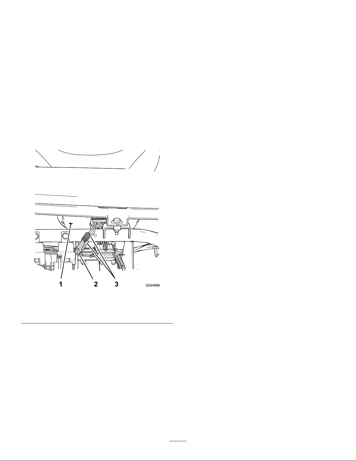
ControlsSystem
Maintenance
Convertingthe
Speedometer
Youcanconvertthespeedometerfrommphtokpm
orkphtomph.
1.Positionthemachineonalevelsurface,shut
offtheengine,engagetheparkingbrake,and
removethekey.
2.Removethehood.
3.Locatethe2loosewiresnexttothemeter
(Figure78).
Figure78
1.Meter(forwardface)3.Speedometerwires
2.Plug
4.Removetheconnectorplugfromtheharness
wireandconnectthewirestogether(Figure78).
Note:Themeterswitchesfrommphto
kph.Retainthepluginordertoconvertthe
speedometertomph.
5.Installthehood.
g024896
58
Page 59

HydraulicSystem
productsonlyfromreputablemanufacturerswhowill
standbehindtheirrecommendation.
Maintenance
HydraulicSystemSafety
•Seekimmediatemedicalattentionifuidisinjected
intoskin.Injecteduidmustbesurgicallyremoved
withinafewhoursbyadoctor.
•Beforedisconnectingorperforminganyworkon
thehydraulicsystem,relieveallpressureinthe
systembyshuttingofftheengine,cyclingthe
dumpvalvefromraisetolower,and/orlowering
thecargobedandattachments.Placetheremote
hydraulicsleverintheoatposition.Donotwork
underaraisedbedwithouttheproperbedsafety
supportinplace.
•Ensurethatallhydraulic-uidhosesandlinesare
ingoodconditionandthatallhydraulicconnections
andttingsaretightbeforeapplyingpressureto
thehydraulicsystem.
•Keepyourhandsandbodyawayfrompinhole
leaksornozzlesthatejecthigh-pressurehydraulic
uid.
•Usecardboardorpapertondhydraulicleaks.
ServicingtheHydraulic
System
HydraulicFluidSpecications
Thereservoirislledatthefactorywithhigh-quality
hydraulicuid.Checkthelevelofthehydraulicuid
beforeyourststarttheengineanddailythereafter;
refertoCheckingtheHydraulic-FluidLevel(page59).
HighViscosityIndex/LowPourPoint
Anti-wearHydraulicFluid,ISOVG46
MaterialProperties:
Viscosity,ASTMD445cSt@40°C(104°F)
ViscosityIndexASTMD2270
PourPoint,ASTMD97-37°Cto-45°C(-34°F
IndustrySpecications:EatonVickers694(I-286-S,
M-2950-S/35VQ25or
44to48
140orhigher
to-49°F)
M-2952-S)
Note:Manyhydraulicuidsarealmostcolorless,
makingitdifculttospotleaks.Areddyeadditivefor
thehydraulicuidisavailablein20ml(0.67oz)
bottles.Abottleissufcientfor15to22L(4to6US
gallons)ofhydraulicuid.OrderPartNo.44-2500
fromyourauthorizedTorodistributor.
CheckingtheHydraulic-Fluid
Level
ServiceInterval:Beforeeachuseordaily—Check
thehydraulic-uidlevel.(Check
thelevelofhydraulicuidbefore
theengineisrststartedanddaily
thereafter.)
Hydraulic-uidcapacityforNon-TCmodel:7.5L
(2USgallons)
Hydraulic-uidcapacityforNon-TCmodelwiththe
HighFlowHydraulicKit(optional)orTCmodel:
15.1L(4USgallons)
1.Parkthemachineonalevelsurface.
Recommendedreplacementuid:T oroPX
ExtendedLifeHydraulicFluid;availablein19L(5US
gallon)pailsor208L(55USgallon)drums.
Note:Amachineusingtherecommended
replacementuidrequireslessfrequentuidandlter
changes.
Alternativeuids:IfT oroPXExtendedLife
HydraulicFluidisnotavailable,youmayuseanother
conventional,petroleum-basedhydraulicuidhaving
specicationsthatfallwithinthelistedrangeforallthe
followingmaterialpropertiesandthatitmeetsindustry
standards.Donotusesyntheticuid.Consultwith
yourlubricantdistributortoidentifyasatisfactory
product.
Note:T orodoesnotassumeresponsibilityfor
damagecausedbyimpropersubstitutions,souse
2.Engagetheparkingbrake.
3.Shutofftheengineandremovethekey.
4.Cleantheareaaroundthellerneckandthe
capofthehydraulicreservoir(Figure79and
Figure80).
59
Page 60
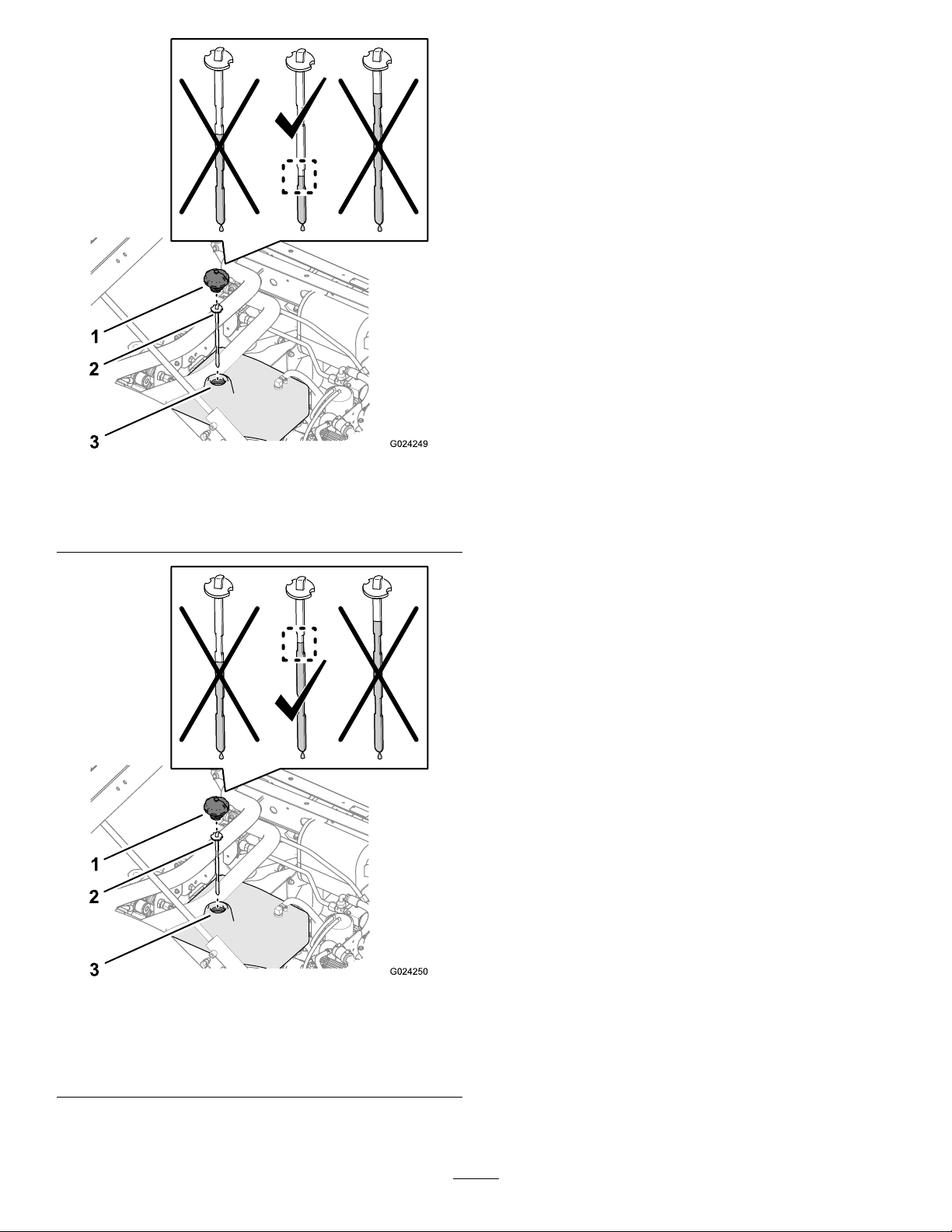
Figure79
Hydraulic-uidlevel(non-TCmodels)
5.Removethecapanddipstickfromthellerneck
ofthereservoirandwipethedipstickcleanwith
arag(Figure79andFigure80).
6.Insertthedipstickintothellerneck;then
removeitandchecktheuidlevel(Figure79
andFigure80).
•Non-TCmodel:Thehydraulic-uidlevel
shouldbebetweenthelowerindentedarea
onthedipstick.
•Non-TCmodelwiththe
High-Flow-HydraulicKit(option)or
TCmodel:Thehydraulic-uidlevelshould
bebetweentheupperindentedareaonthe
dipstick.
7.Ifthelevelislow,addthespeciedhydraulic
uidintothereservoirtoraisetheleveltothe
middleoftheindentedareaonthedipstick
(Figure79andFigure80).
8.Installthedipstickandcaptothellerneckof
g024249
thereservoir(Figure79andFigure80).
1.Cap
2.Dipstick3.Fillerneck
Figure80
Hydraulic-uidlevel(non-TCmodelwiththeHighFlow
HydraulicKit(optionalkit)orTCmodel)
1.Cap
2.Dipstick3.Fillerneck
g024250
60
Page 61
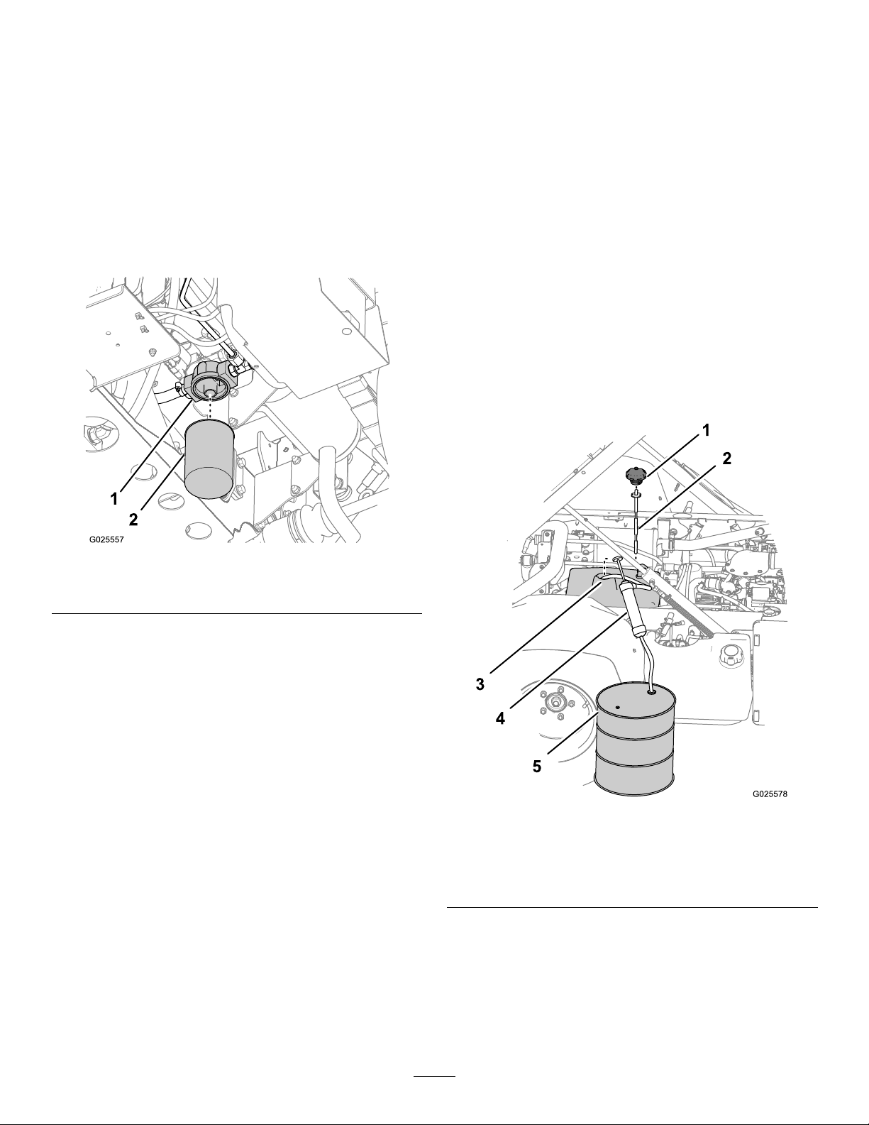
ReplacingtheHydraulicFilter
ChangingtheHydraulicFluid
ServiceInterval:Every1,000hours—Ifyouare
usingtherecommendedhydraulic
uid,replacethehydrauliclter.
Important:Useofanyotherltermayvoidthe
warrantyonsomecomponents.
1.Parkthemachineonalevelsurface,shutoffthe
engine,engagetheparkingbrake,andremove
thekey.
2.Cleantheareaaroundlter-mountingarea
(Figure81).
ServiceInterval:Every2,000hours—Ifyouare
usingtherecommendedhydraulic
uid,changethehydraulicuid.
Every800hours—Ifyouarenotusingthe
recommendedhydraulicuidorhaveeverlled
thereservoirwithanalternativeuid,replace
thehydraulicuidandlter.
Hydraulic-uidcapacityforNon-TCmodel:7.5L
(2USgallons)
Hydraulic-uidcapacityforNon-TCmodelwiththe
HighFlowHydraulicKit(optional)orTCmodel:
15.1L(4USgallons)
1.Parkthemachineonalevelsurface,shutoffthe
engine,engagetheparkingbrake,andremove
thekey.
2.Raisethecargobed.
3.Removethecapanddipstickfromthellerneck
ofthehydraulictank(Figure82).
Figure81
1.Filteradapter
2.Hydrauliclter
3.Placeadrainpanunderthelter(Figure81).
4.Removethelterbyrotatingitcounterclockwise
(Figure81).
5.Cleanthelter-seatingsurfaceofthelter
adapter(Figure81).
6.Lubricatethegasketonthenewlterwiththe
speciedhydraulicuid.
7.Threadthelterontothelteradapteruntilthe
gasketoftheltercontactstheseatingsurface
oftheadapter(Figure81),andthentightenthe
lteranadditional1/2turn(Figure81).
8.Starttheengineandletitrunforabout2minutes
topurgeairfromthesystem.
9.Shutofftheengineandcheckthehydraulic-uid
levelinthehydraulictankandthelterareafor
leaks.
g025557
g025578
Figure82
1.Cap4.Siphonequipment
2.Dipstick
3.Fillerneck(hydraulictank)
5.Collectioncontainer
4.Routetheintakehoseofthesiphoning
equipmentthroughthellerneckofthehydraulic
tankandtothebottomofthetank(Figure82).
5.Directthedischargehoseofthesiphoning
equipmentintoacollectioncontainer(Figure82)
witha11.4L(3USgallon)capacity—Non-TC
modelor18.9L(5USgallon)capacity—Non-TC
61
Page 62
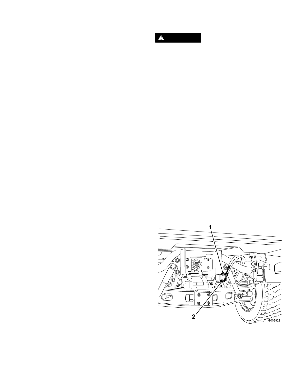
modelwiththeHighFlowHydraulicKit(option)
orTCmodel.
6.Siphonthehydraulicuidfromthehydraulic
tank.
7.Removethesiphoningequipmentfromthe
hydraulictank(Figure82).
8.Add7.5L(2USgallons)—Non-TCmodelor
15.1L(4USgallons)—Non-TCmodelwiththe
HighFlowHydraulicKit(option)orTCmodelof
thespeciedhydraulicuidintothehydraulic
tank(Figure82).
Important:Useonlythehydraulicuids
specied.Otheruidscouldcausesystem
damage.
9.Installthedipstickandcaptothellerneckof
thehydraulictank(Figure82).
10.Starttheengineandoperatethemachinetoll
thehydraulicsystem.
11.Checkthehydraulic-uidlevelandreplenishit,
ifrequired.
RaisingtheCargoBedin
anEmergency
Thecargobedcanberaisedinanemergencywithout
startingtheenginebycrankingstarterorbyjumping
thehydraulicsystem.
RaisingtheCargoBedusingthe
Starter
RaisingtheCargoBedbyJumping
theHydraulicSystem
CAUTION
Araisedbedfullofmaterialwithouttheproper
safetysupportrodmaylowerunexpectedly.
Workingunderanunsupportedraisedbed
maycauseinjurytoyouorothers.
•Beforeservicingormakingadjustmentsto
themachine,parkthemachineonalevel
surface,engagetheparkingbrake,shutoff
theengine,andremovethekey.
•Removeanyloadmaterialfromthebed
orotherattachmentandinsertthesafety
supportonafullyextendedcylinderrod
beforeworkingunderaraisedbed.
Youwillneed2hydraulichoses,eachwithamale
andfemalequickcoupler,thattthemachine
couplers,toperformthisoperation.
1.Backanothermachineuptotherearofthe
disabledmachine.
Important:Themachinehydraulicsystem
usesDexronIIIATF.T oavoidsystem
contamination,makesurethatthemachine
usedtojumpthehydraulicsystemusesan
equivalentuid.
2.Onbothmachine,disconnectthe2quick-coupler
hosesfromthehosessecuredtothecoupler
bracket(Figure83).
Crankthestarterwhileholdingtheliftleverinthe
Raiseposition.Runthestarterfor10seconds,then
wait60secondsbeforeengagingthestarteragain.
Iftheenginedoesnotcrank,youmustremovethe
loadandbed(attachment)toservicetheengineor
transaxle.
g009822
Figure83
1.Quick-couplerhoseA
2.Quick-couplerhoseB
62
Page 63
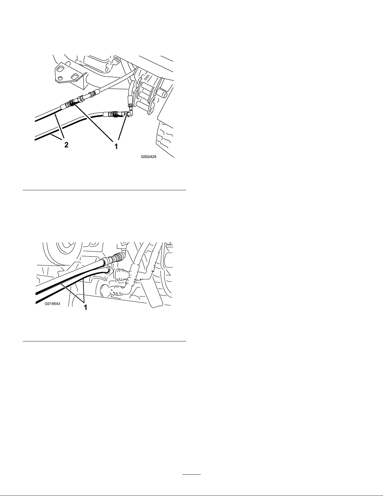
3.Onthedisabledmachine,connectthe2jumper
hosestothehosesthatweredisconnected
(Figure84).
11.Aftercompletingtheoperation,removethe
jumperhosesandconnectthehydraulichoses
tobothmachines.
4.Captheunusedttings.
Figure84
1.Disconnectedhoses2.Jumperhoses
5.Ontheothermachine,connectthe2hosesto
thecouplerstillinthecouplerbracket(connect
thetophosetothetopcouplerandthebottom
hosetothebottomcoupler)(Figure85).
Important:Checkthehydraulicuid
levels,inbothmachines,beforeresuming
operation.
g002429
6.Captheunusedttings.
Figure85
1.Jumperhoses
7.Keepallbystandersawayfromthemachines.
8.Startthesecondmachineandmovetheliftlever
totheraiseposition,whichraisesthedisabled
cargobed.
9.Movethehydraulic-liftlevertotheNEUTRAL
position,andengagethelift-leverlock.
10.Installthebedsupportontotheextendedlift
cylinder;refertoUsingtheBedSupport(page
35).
g019543
Note:Withboththemachineturnedoff,move
theliftleverbackandforthtoremovethesystem
pressureandeasethedisconnectionofthe
quickcouplers.
63
Page 64

Cleaning
WashingtheMachine
ServiceInterval:Beforeeachuseordaily—Wash
themachine.
Washthemachineasneededusingwateralone
orwithamilddetergent.Y oumayusearagwhen
washingthemachine.
Important:Donotusebrackishorreclaimed
watertocleanthemachine.
Important:Donotusepower-washingequipment
towashthemachine.Power-washingequipment
maydamagetheelectricalsystem,loosen
importantdecals,orwashawaynecessarygrease
atfrictionpoints.Avoidexcessiveuseofwater
nearthecontrolpanel,engine,andbattery.
Important:Donotwashthemachinewiththe
enginerunning.Washingthemachinewiththe
enginerunningmayresultininternalengine
damage.
64
Page 65

Storage
StorageSafety
•Shutoffthemachine,removethekey(ifequipped),
andwaitforallmovementtostopbeforeyouleave
theoperator’sposition.Allowthemachinetocool
beforeadjusting,servicing,cleaning,orstoringit.
•Donotstorethemachineorfuelcontainerwhere
thereisanopename,spark,orpilotlight,such
asonawaterheaterorotherappliance.
durationrecommendedbythefuel
stabilizermanufacturer.
B.Runtheenginetodistributeconditionedfuel
throughthefuelsystemfor5minutes.
C.Shutofftheengine,allowittocool,and
drainthefueltank.
D.Starttheengineandrunituntilitstops.
E.Startandruntheengineagainuntilitdoes
notstartagain.
F.Disposeofdrainedfuelproperly.Recycle
asperlocalcodes.
StoringtheMachine
ServiceInterval:Every200hours—Inspectthe
serviceandparkingbrakes.
Every400hours—Visuallyinspectthebrakes
forwornbrakeshoes.
Yearly
1.Positionthemachineonalevelsurface,engage
theparkingbrake,shutofftheengine,and
removethekeyfromthekeyswitch.
2.Cleandirtandgrimefromtheentiremachine,
includingtheoutsideoftheenginecylinderhead
nsandblowerhousing.
Important:Youcanwashthemachine
withmilddetergentandwater.Donot
usehigh-pressurewatertowashthe
machine.Pressurewashingthemachine
maydamagetheelectricalsystemorwash
awaynecessarygreaseatfrictionpoints.
Avoidexcessiveuseofwater,especiallynear
thecontrolpanel,lights,engine,andbattery.
3.Checkandadjustthebrakepedalandparking
brake,ifnecessary;refertoAdjustingtheBrake
Pedal(page57)andAdjustingtheParking
Brake(page56).
4.Servicetheaircleaner;refertoServicingtheAir
Filter(page40).
5.Greasethemachine;refertoGreasingthe
BearingsandtheBushings(page39).
6.Changetheengineoilandlter;referto
ServicingtheEngineOil(page41).
7.Checkthetirepressure;refertoCheckingthe
TirePressure(page21).
8.Forstorageover30days,preparethefuel
systemasfollows:
A.Addapetroleumbased
stabilizer/conditionertothefuelinthe
tank.Donotuseanalcohol-basedstabilizer
(ethanolormethanol).
Important:Donotstorefuelcontaining
stabilizer/conditionerlongerthanthe
9.Removethesparkplugsandchecktheir
condition;refertoServicingtheSparkPlugs
(page43).
10.Withthesparkplugsremovedfromtheengine,
pour15ml(2tablespoons)ofengineoilintothe
spark-plughole.
11.Usethestartertocranktheengineanddistribute
theoilinsidethecylinder.
12.Installthesparkplugsandtighteneachoneto
therecommendedtorque;refertoServicingthe
SparkPlugs(page43).
Note:Donotinstallthespark-plugwiresonthe
sparkplugs.
13.Checktheantifreezeprotectionandadda50/50
solutionofwaterandantifreezeasneededfor
expectedminimumtemperatureinyourarea.
14.Removethebatteryfromthechassis,and
chargeitfully;refertoServicingtheBattery
(page47).
Note:Donotconnectthebatterycablestothe
batterypostsduringstorage.
Important:Thebatterymustbefully
chargedtopreventitfromfreezingandbeing
damagedattemperaturesbelow0°C(32°F).
Afullychargedbatterymaintainsitscharge
forabout50daysattemperatureslower
than4°C(40°F).Ifthetemperatureswillbe
above4°C(40°F),checkthewaterlevelinthe
batteryandchargeitevery30days.
15.Checkandtightenallfasteners.Repairor
replaceanypartthatisdamaged.
16.Paintallscratchedorbaremetalsurfaces
withpaintavailablefromyourauthorizedToro
distributor.
17.Storethemachineinaclean,drygarageor
storagearea.
18.Removethekeyfromthekeyswitchandputitin
asafeplacethatisoutofthereachofchildren.
19.Coverthemachinetoprotectitandkeepitclean.
65
Page 66

Troubleshooting
Problem
Thequickcouplersaredifcultto
connectordisconnect.
Thepowersteeringmoveshard.
Anattachmentdoesnotfunction.
Asquealingnoiseisheard.
PossibleCauseCorrectiveAction
1.Thehydraulicpressurenotrelieved
(thequickcouplerisunderpressure).
1.Thehydraulic-uidlevelislow.1.Servicethehydraulicreservoir.
2.Thehydraulicuidishot.2.Checkthehydraulic-uidleveland
3.Thehydraulicpumpnotoperating.
1.Thettingisloose.1.Tightenthetting. Thehydraulicttingleaks.
2.Thehydraulicttingismissingan
O-ring.
1.Thequickcouplersarenotfully
connected.
2.Thequickcouplersareinterchanged.2.Disconnectthequickcouplings,align
1.TheHydraulic-liftleverislockedinthe
ONposition(causinghydraulicuidto
owoverthereliefvalve).
1.Shutofftheengine,movethe
hydraulic-liftleverforwardand
backwardseveraltimes,andconnect
thequickcouplersforthettingsinthe
auxiliaryhydraulicpanel.
serviceifitislow.Contactan
AuthorizedServiceDealer .
3.ContactanAuthorizedServiceDealer.
2.InstallthemissingO-ring.
1.Disconnectthequickcouplings,
removeanddebrisfromthecouplings,
connectthecouplings.Replaceany
damagedcouplings.
thecouplingstothecorrectportson
theauxiliaryhydraulicpanel,connect
thecouplings.
1.Setthehydraulic-liftlocktotheUNLOCK
positionandmovethehydraulic-lift
levertoNEUTRAL.
Theenginedoesnotstart.
Thetransmissionishardtoshift.
Theclutchengagementisabrupt.
1.Thehydraulic-liftleverislockedinthe
ONposition.
1.Theengine-idlerpmissettoofast.
2.Theclutchesaredirty .
1.Theengineidleistooslow.1.Adjusttheenginelowidleto1,250to
2.Thebeltisnew.
3.Theacceleratorpedalfreeplayistoo
large.
4.Theclutchedaredirty .
1.Setthehydraulic-liftlocktotheUNLOCK
position,movethehydraulic-liftleverto
NEUTRAL,andstarttheengine.
1.Adjusttheenginelowidleto1,250to
1,350rpm.
2.Cleantheclutches.
1,350rpm.
2.Allow10hoursofnormaloperationfor
thebeltbreak-inperiod.
3.Adjusttheacceleratorpedal.
4.Cleantheclutches.
66
Page 67

Notes:
Page 68

Notes:
Page 69

Notes:
Page 70

CaliforniaProposition65WarningInformation
Whatisthiswarning?
Youmayseeaproductforsalethathasawarninglabellikethefollowing:
WARNING:CancerandReproductiveHarm—www.p65Warnings.ca.gov.
WhatisProp65?
Prop65appliestoanycompanyoperatinginCalifornia,sellingproductsinCalifornia,ormanufacturingproductsthatmaybesoldinorbroughtinto
California.ItmandatesthattheGovernorofCaliforniamaintainandpublishalistofchemicalsknowntocausecancer,birthdefects,and/orother
reproductiveharm.Thelist,whichisupdatedannually,includeshundredsofchemicalsfoundinmanyeverydayitems.ThepurposeofProp65isto
informthepublicaboutexposuretothesechemicals.
Prop65doesnotbanthesaleofproductscontainingthesechemicalsbutinsteadrequireswarningsonanyproduct,productpackaging,orliteraturewith
theproduct.Moreover,aProp65warningdoesnotmeanthataproductisinviolationofanyproductsafetystandardsorrequirements.Infact,the
CaliforniagovernmenthasclariedthataProp65warning“isnotthesameasaregulatorydecisionthataproductis‘safe’or‘unsafe.’”Manyofthese
chemicalshavebeenusedineverydayproductsforyearswithoutdocumentedharm.Formoreinformation,gotohttps://oag.ca.gov/prop65/faqs-view-all
AProp65warningmeansthatacompanyhaseither(1)evaluatedtheexposureandhasconcludedthatitexceedsthe“nosignicantrisklevel”;or(2)
haschosentoprovideawarningbasedonitsunderstandingaboutthepresenceofalistedchemicalwithoutattemptingtoevaluatetheexposure.
Doesthislawapplyeverywhere?
Prop65warningsarerequiredunderCalifornialawonly.ThesewarningsareseenthroughoutCaliforniainawiderangeofsettings,includingbutnot
limitedtorestaurants,grocerystores,hotels,schools,andhospitals,andonawidevarietyofproducts.Additionally,someonlineandmailorder
retailersprovideProp65warningsontheirwebsitesorincatalogs.
.
HowdotheCaliforniawarningscomparetofederallimits?
Prop65standardsareoftenmorestringentthanfederalandinternationalstandards.TherearevarioussubstancesthatrequireaProp65warning
atlevelsthatarefarlowerthanfederalactionlimits.Forexample,theProp65standardforwarningsforleadis0.5μg/day,whichiswellbelow
thefederalandinternationalstandards.
Whydon’tallsimilarproductscarrythewarning?
•ProductssoldinCaliforniarequireProp65labellingwhilesimilarproductssoldelsewheredonot.
•AcompanyinvolvedinaProp65lawsuitreachingasettlementmayberequiredtouseProp65warningsforitsproducts,butothercompanies
makingsimilarproductsmayhavenosuchrequirement.
•TheenforcementofProp65isinconsistent.
•CompaniesmayelectnottoprovidewarningsbecausetheyconcludethattheyarenotrequiredtodosounderProp65;alackofwarningsfora
productdoesnotmeanthattheproductisfreeoflistedchemicalsatsimilarlevels.
WhydoesToroincludethiswarning?
Torohaschosentoprovideconsumerswithasmuchinformationaspossiblesothattheycanmakeinformeddecisionsabouttheproductstheybuyand
use.T oroprovideswarningsincertaincasesbasedonitsknowledgeofthepresenceofoneormorelistedchemicalswithoutevaluatingthelevelof
exposure,asnotallthelistedchemicalsprovideexposurelimitrequirements.WhiletheexposurefromToroproductsmaybenegligibleorwellwithinthe
“nosignicantrisk”range,outofanabundanceofcaution,TorohaselectedtoprovidetheProp65warnings.Moreover,ifTorodoesnotprovidethese
warnings,itcouldbesuedbytheStateofCaliforniaorbyprivatepartiesseekingtoenforceProp65andsubjecttosubstantialpenalties.
RevA
Page 71

EEA/UKPrivacyNotice
Toro’sUseofYourPersonalInformation
TheT oroCompany(“T oro”)respectsyourprivacy.Whenyoupurchaseourproducts,wemaycollectcertainpersonalinformationaboutyou,eitherdirectly
fromyouorthroughyourlocalT orocompanyordealer.T orousesthisinformationtofullcontractualobligations-suchastoregisteryourwarranty ,
processyourwarrantyclaimortocontactyouintheeventofaproductrecall-andforlegitimatebusinesspurposes-suchastogaugecustomer
satisfaction,improveourproductsorprovideyouwithproductinformationwhichmaybeofinterest.T oromayshareyourinformationwithoursubsidiaries,
afliates,dealersorotherbusinesspartnersinconnectiontheseactivities.Wemayalsodisclosepersonalinformationwhenrequiredbylaworin
connectionwiththesale,purchaseormergerofabusiness.Wewillneversellyourpersonalinformationtoanyothercompanyformarketingpurposes.
RetentionofyourPersonalInformation
Torowillkeepyourpersonalinformationaslongasitisrelevantfortheabovepurposesandinaccordancewithlegalrequirements.Formoreinformation
[email protected].
Toro’sCommitmenttoSecurity
YourpersonalinformationmaybeprocessedintheUSoranothercountrywhichmayhavelessstrictdataprotectionlawsthanyourcountryofresidence.
Wheneverwetransferyourinformationoutsideofyourcountryofresidence,wewilltakelegallyrequiredstepstoensurethatappropriatesafeguardsare
inplacetoprotectyourinformationandtomakesureitistreatedsecurely.
AccessandCorrection
Youmayhavetherighttocorrectorreviewyourpersonaldata,orobjecttoorrestricttheprocessingofyourdata.Todoso,pleasecontactusbyemail
[email protected] orohashandledyourinformation,weencourageyoutoraisethisdirectlywithus.
PleasenotethatEuropeanresidentshavetherighttocomplaintoyourDataProtectionAuthority.
374-0282RevC
Page 72

TheToroWarranty
Two-Y earor1,500HoursLimitedWarranty
ConditionsandProductsCovered
TheToroCompanyanditsafliate,T oroWarrantyCompany,pursuant
toanagreementbetweenthem,jointlywarrantyourT oroCommercial
product(“Product”)tobefreefromdefectsinmaterialsorworkmanship
for2yearsor1,500operationalhours*,whicheveroccursrst.This
warrantyisapplicabletoallproductswiththeexceptionofAerators
(refertoseparatewarrantystatementsfortheseproducts).Wherea
warrantableconditionexists,wewillrepairtheProductatnocosttoyou
includingdiagnostics,labor,parts,andtransportation.Thiswarranty
beginsonthedatetheProductisdeliveredtotheoriginalretailpurchaser.
*Productequippedwithanhourmeter.
InstructionsforObtainingWarrantyService
YouareresponsiblefornotifyingtheCommercialProductsDistributoror
AuthorizedCommercialProductsDealerfromwhomyoupurchasedthe
Productassoonasyoubelieveawarrantableconditionexists.Ifyouneed
helplocatingaCommercialProductsDistributororAuthorizedDealer,or
ifyouhavequestionsregardingyourwarrantyrightsorresponsibilities,
youmaycontactusat:
ToroCommercialProductsServiceDepartment
ToroWarrantyCompany
811 1LyndaleAvenueSouth
Bloomington,MN55420-1196
952–888–8801or800–952–2740
E-mail:[email protected]
OwnerResponsibilities
Astheproductowner,youareresponsibleforrequiredmaintenanceand
adjustmentsstatedinyourOperator'sManual.Repairsforproductissues
causedbyfailuretoperformrequiredmaintenanceandadjustmentsarenot
coveredunderthiswarranty.
ItemsandConditionsNotCovered
Notallproductfailuresormalfunctionsthatoccurduringthewarranty
periodaredefectsinmaterialsorworkmanship.Thiswarrantydoesnot
coverthefollowing:
•Productfailureswhichresultfromtheuseofnon-Tororeplacement
parts,orfrominstallationanduseofadd-on,ormodiednon-Toro
brandedaccessoriesandproducts.
•Productfailureswhichresultfromfailuretoperformrecommended
maintenanceand/oradjustments.
•ProductfailureswhichresultfromoperatingtheProductinanabusive,
negligent,orrecklessmanner.
•Partsconsumedthroughusethatarenotdefective.Examplesofparts
whichareconsumed,orusedup,duringnormalProductoperation
include,butarenotlimitedto,brakepadsandlinings,clutchlinings,
blades,reels,rollersandbearings(sealedorgreasable),bedknives,
sparkplugs,castorwheelsandbearings,tires,lters,belts,andcertain
sprayercomponentssuchasdiaphragms,nozzles,andcheckvalves.
•Failurescausedbyoutsideinuence,including,butnotlimitedto,
weather,storagepractices,contamination,useofunapprovedfuels,
coolants,lubricants,additives,fertilizers,water ,orchemicals.
•Failureorperformanceissuesduetotheuseoffuels(e.g.gasoline,
diesel,orbiodiesel)thatdonotconformtotheirrespectiveindustry
standards.
•Normalnoise,vibration,wearandtear,anddeterioration.Normal
“wearandtear”includes,butisnotlimitedto,damagetoseatsdueto
wearorabrasion,wornpaintedsurfaces,scratcheddecalsorwindows.
Parts
Partsscheduledforreplacementasrequiredmaintenancearewarranted
fortheperiodoftimeuptothescheduledreplacementtimeforthatpart.
Partsreplacedunderthiswarrantyarecoveredforthedurationofthe
originalproductwarrantyandbecomethepropertyofT oro.T orowillmake
thenaldecisionwhethertorepairanyexistingpartorassemblyorreplace
it.T oromayuseremanufacturedpartsforwarrantyrepairs.
DeepCycleandLithium-IonBatteryWarranty
DeepcycleandLithium-Ionbatterieshaveaspeciedtotalnumber
ofkilowatt-hourstheycandeliverduringtheirlifetime.Operating,
recharging,andmaintenancetechniquescanextendorreducetotal
batterylife.Asthebatteriesinthisproductareconsumed,theamount
ofusefulworkbetweenchargingintervalswillslowlydecreaseuntilthe
batteryiscompletelywornout.Replacementofwornoutbatteries,
duetonormalconsumption,istheresponsibilityoftheproductowner.
Note:(Lithium-Ionbatteryonly):Pro-ratedafter2years.Refertothe
batterywarrantyforadditionalinformation.
LifetimeCrankshaftWarranty(ProStripe02657Model
Only)
TheProstripewhichisttedwithagenuineT oroFrictionDiscand
Crank-SafeBladeBrakeClutch(integratedBladeBrakeClutch(BBC)+
FrictionDiscassembly)asoriginalequipmentandusedbytheoriginal
purchaserinaccordancewithrecommendedoperatingandmaintenance
procedures,arecoveredbyaLifetimeWarrantyagainstenginecrankshaft
bending.Machinesttedwithfrictionwashers,BladeBrakeClutch(BBC)
unitsandothersuchdevicesarenotcoveredbytheLifetimeCrankshaft
Warranty.
MaintenanceisatOwner’sExpense
Enginetune-up,lubrication,cleaningandpolishing,replacementoflters,
coolant,andcompletingrecommendedmaintenancearesomeofthe
normalservicesT oroproductsrequirethatareattheowner’sexpense.
GeneralConditions
RepairbyanAuthorizedToroDistributororDealerisyoursoleremedy
underthiswarranty.
NeitherTheToroCompanynorToroWarrantyCompanyisliablefor
indirect,incidentalorconsequentialdamagesinconnectionwiththe
useoftheToroProductscoveredbythiswarranty,includingany
costorexpenseofprovidingsubstituteequipmentorserviceduring
reasonableperiodsofmalfunctionornon-usependingcompletion
ofrepairsunderthiswarranty.ExceptfortheEmissionswarranty
referencedbelow,ifapplicable,thereisnootherexpresswarranty .All
impliedwarrantiesofmerchantabilityandtnessforusearelimitedto
thedurationofthisexpresswarranty.
Somestatesdonotallowexclusionsofincidentalorconsequential
damages,orlimitationsonhowlonganimpliedwarrantylasts,sotheabove
exclusionsandlimitationsmaynotapplytoyou.Thiswarrantygivesyou
speciclegalrights,andyoumayalsohaveotherrightswhichvaryfrom
statetostate.
NoteRegardingEmissionsWarranty
TheEmissionsControlSystemonyourProductmaybecoveredby
aseparatewarrantymeetingrequirementsestablishedbytheU.S.
EnvironmentalProtectionAgency(EP A)and/ortheCaliforniaAirResources
Board(CARB).Thehourlimitationssetforthabovedonotapplytothe
EmissionsControlSystemWarranty.RefertotheEngineEmissionControl
WarrantyStatementsuppliedwithyourproductorcontainedintheengine
manufacturer’sdocumentation.
CountriesOtherthantheUnitedStatesorCanada
CustomerswhohavepurchasedT oroproductsexportedfromtheUnitedStatesorCanadashouldcontacttheirT oroDistributor(Dealer)toobtain
guaranteepoliciesforyourcountry ,province,orstate.IfforanyreasonyouaredissatisedwithyourDistributor'sserviceorhavedifcultyobtaining
guaranteeinformation,contactyourAuthorizedToroServiceCenter .
374-0253RevF
 Loading...