

Toro Workman 07040, Workman 07042, Workman 07059, Workman 07060, Workman 07132 Operator's Manual
...Page 1
FormNo.3421-347RevA
Workman
®
GTXGasoline/Petrol
UtilityVehicle
ModelNo.07040—SerialNo.401400001andUp
ModelNo.07042—SerialNo.401400001andUp
ModelNo.07059—SerialNo.400000000andUp
ModelNo.07060—SerialNo.400000000andUp
ModelNo.07130TC—SerialNo.400000000andUp
ModelNo.07132—SerialNo.400000000andUp
ModelNo.07132TC—SerialNo.400000000andUp
ModelNo.07152—SerialNo.400000000andUp
Registeratwww.T oro.com.
OriginalInstructions(EN)
*3421-347*A
Page 2
ThisproductcomplieswithallrelevantEuropean
directives;fordetails,pleaseseetheseparateproduct
specicDeclarationofConformity(DOC)sheet.
WARNING
CALIFORNIA
Proposition65Warning
Thisproductcontainsachemical
orchemicalsknowntotheStateof
Californiatocausecancer,birthdefects,
orreproductiveharm.
Theengineexhaustfromthisproduct
containschemicalsknowntotheStateof
Californiatocausecancer,birthdefects,
orotherreproductiveharm.
ItisaviolationofCaliforniaPublicResourceCode
Section4442or4443touseoroperatetheengineon
anyforest-covered,brush-covered,orgrass-covered
landunlesstheengineisequippedwithaspark
arrester,asdenedinSection4442,maintainedin
effectiveworkingorderortheengineisconstructed,
equipped,andmaintainedforthepreventionofre.
Pleaserefertotheenginemanufacturer’sinformation
includedwiththemachine.
Introduction
Important:Withyourmobiledevice,youcan
scantheQRcodeontheserialnumberdecal(if
equipped)toaccesswarranty,parts,andother
productinformation.
g235847
Figure1
BottomofSeatAssemblyShown
1.Modelandserial-numberlocation
ModelNo.
SerialNo.
Thismanualidentiespotentialhazardsandhas
safetymessagesidentiedbythesafety-alertsymbol
(Figure2),whichsignalsahazardthatmaycause
seriousinjuryordeathifyoudonotfollowthe
recommendedprecautions.
Thisutilityvehicleisintendedtobeprimarilyused
off-highwaytotransportpeopleandmaterialloads.
Readthisinformationcarefullytolearnhowtooperate
andmaintainyourproductproperlyandtoavoid
injuryandproductdamage.Youareresponsiblefor
operatingtheproductproperlyandsafely .
YoumaycontactT orodirectlyatwww.T oro.com
forproductsafetyandoperationtrainingmaterials,
accessoryinformation,helpndingadealer,orto
registeryourproduct.
Wheneveryouneedservice,genuineToroparts,or
additionalinformation,contactanAuthorizedService
DistributororT oroCustomerServiceandhavethe
modelandserialnumbersofyourproductready .
Figure1identiesthelocationofthemodelandserial
numbersontheproduct.Writethenumbersinthe
spaceprovided.
g000502
Figure2
Safety-alertsymbol
Thismanualuses2wordstohighlightinformation.
Importantcallsattentiontospecialmechanical
informationandNoteemphasizesgeneralinformation
worthyofspecialattention.
©2018—TheToro®Company
8111LyndaleAvenueSouth
Bloomington,MN55420
Contactusatwww.Toro.com.
2
PrintedintheUSA
AllRightsReserved
Page 3

Contents
Safety.......................................................................4
GeneralSafety...................................................4
SafetyandInstructionalDecals..........................5
Setup........................................................................9
1InstallingtheSteeringWheel(International
ModelsOnly)...................................................9
2CheckingtheFluidLevelsandTire
Pressure.........................................................9
3BurnishingtheBrakes....................................10
4ReadingtheManualandViewingthe
SetupMaterial...............................................10
ProductOverview....................................................11
Controls...........................................................12
Specications..................................................15
Attachments/Accessories.................................15
BeforeOperation.................................................16
BeforeOperationSafety...................................16
PerformingDailyMaintenance..........................16
CheckingtheTirePressure...............................16
AddingFuel......................................................17
BreakinginaNewMachine..............................17
DuringOperation.................................................18
DuringOperationSafety...................................18
OperatingtheCargoBed..................................20
UsingtheRearCargoBedAccessory
Mount............................................................22
LoadingtheCargoBed.....................................23
StartingtheEngine...........................................23
StoppingtheMachine.......................................24
ParkingtheMachine.........................................24
AfterOperation....................................................24
AfterOperationSafety......................................24
TransportingtheMachine.................................24
TowingtheMachine..........................................25
TowingaTrailer................................................25
Maintenance...........................................................26
RecommendedMaintenanceSchedule(s)...........27
DailyMaintenanceChecklist.............................28
MaintainingtheMachineunderSpecial
OperatingConditions....................................28
Pre-MaintenanceProcedures..............................29
MaintenanceSafety..........................................29
PreparingtheMachineforMaintenance............29
LiftingtheMachine...........................................30
AccessingtheHood..........................................30
RaisingandLoweringtheSeat
Assembly......................................................31
RemovingtheSeatAssembly...........................31
InstallingtheSeatAssembly.............................31
Lubrication..........................................................32
GreasingtheMachine.......................................32
GreasingtheFrontWheelBearings..................32
EngineMaintenance...........................................35
EngineSafety...................................................35
ServicingtheAirCleaner..................................35
ServicingtheEngineOil....................................37
ServicingtheSparkPlug...................................38
AdjustingtheHigh/LowIdle..............................39
FuelSystemMaintenance...................................39
InspectingFuelLinesandConnections.............39
ReplacingtheFuelFilter...................................39
ServicingtheCarbonCanister..........................40
ElectricalSystemMaintenance...........................41
ElectricalSystemSafety...................................41
ServicingtheBattery.........................................41
ReplacingtheFuses.........................................43
MaintainingtheHeadlights...............................44
DriveSystemMaintenance..................................45
MaintainingtheTires........................................45
AdjustingtheFrontWheelAlignment................45
CheckingtheTransaxle-FluidLevel..................47
ChangingtheTransaxleFluid...........................47
CheckingtheNeutralGear-Shift
Position.........................................................47
AdjustingtheNeutralGear-Shift
Position.........................................................48
MaintainingthePrimary-DriveClutch................48
ReducingtheT opSpeed...................................49
CoolingSystemMaintenance..............................50
CleaningtheEngine-CoolingAreas..................50
BrakeMaintenance.............................................50
CheckingtheParkingBrake.............................50
AdjustingtheParkingBrake..............................50
CheckingtheBrake-FluidLevel........................51
InspectingtheBrakes.......................................51
ChangingtheBrakeFluid.................................51
BeltMaintenance................................................52
ServicingtheDriveBelt.....................................52
AdjustingtheStarter-GeneratorBelt.................52
ChassisMaintenance...........................................53
AdjustingtheCargo-BedLatches.....................53
Cleaning..............................................................53
WashingtheMachine.......................................53
Storage...................................................................54
StorageSafety..................................................54
StoringtheMachine..........................................54
3
Page 4

Safety
Improperuseormaintenancebytheoperatoror
ownercanresultininjury.T oreducethepotential
forinjury,complywiththesesafetyinstructions
andalwayspayattentiontothesafety-alert
symbol(Figure2),whichmeansCaution,Warning,
orDanger—personalsafetyinstruction.Failureto
complywiththeinstructionmayresultinpersonal
injuryordeath.
Thismachinehasbeendesignedinaccordancewith
therequirementsofSAEJ2258.
GeneralSafety
Thisproductiscapableofcausingpersonalinjury.
Alwaysfollowallsafetyinstructionstoavoidserious
personalinjury.
Usingthisproductforpurposesotherthanitsintended
usecouldprovedangeroustoyouandbystanders.
•Readandunderstandthecontentsofthis
Operator’sManualbeforeyoustarttheengine.
Ensurethateveryoneusingthisproductknows
howtouseitandunderstandsthewarnings.
•Useyourfullattentionwhileoperatingthe
machine.Donotengageinanyactivitythat
causesdistractions;otherwise,injuryorproperty
damagemayoccur.
•Donotputyourhandsorfeetnearmoving
componentsofthemachine.
•Donotoperatethemachinewithoutallguards
andothersafetyprotectivedevicesinplaceand
workingonthemachine.
•Keepthemachineasafedistanceawayfrom
bystanderswhileitismoving.
•Keepchildrenoutoftheoperatingarea.Never
allowchildrentooperatethemachine.
•Stopthemachine,shutofftheengine,andremove
thekeybeforeservicingorfueling.
Improperlyusingormaintainingthismachinecan
resultininjury.Toreducethepotentialforinjury ,
complywiththesesafetyinstructionsandalwayspay
attentiontothesafety-alertsymbol,whichmeans
Caution,Warning,orDanger—personalsafety
instruction.Failuretocomplywiththeseinstructions
mayresultinpersonalinjuryordeath.
Youcanndadditionalsafetyinformationwhere
neededthroughoutthismanual.
4
Page 5
SafetyandInstructionalDecals
Safetydecalsandinstructionsareeasilyvisibletotheoperatorandarelocatednearanyarea
ofpotentialdanger.Replaceanydecalthatisdamagedormissing.
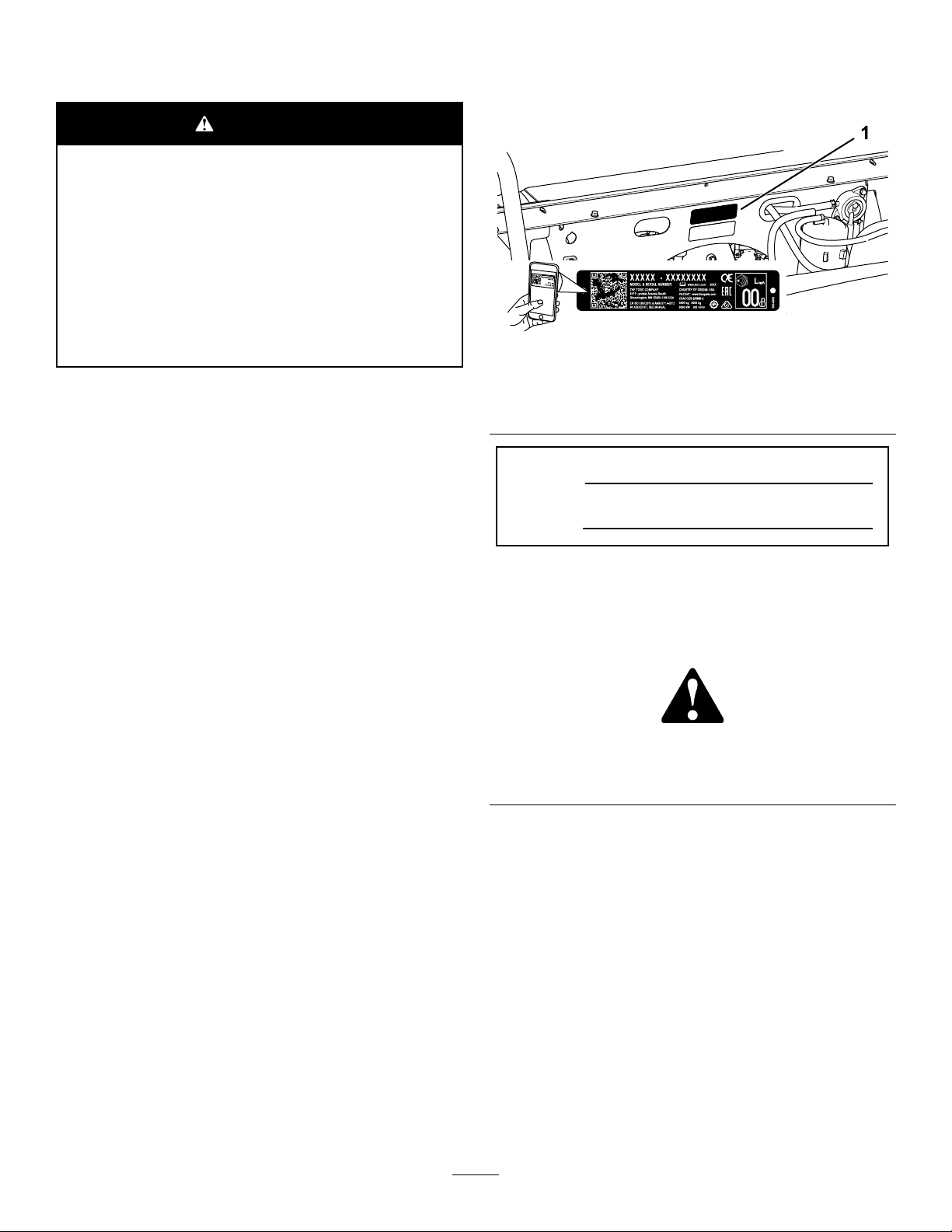
99-7345
1.Warning—readtheOperator'sManual.
2.Hotsurface/burnhazard—stayasafedistanceawayfrom
thehotsurface.
3.Entanglementhazard,belt—stayawayfrommovingparts;
keepallguardsinplace.
4.Crushinghazard,cargobed—usetheproprodtosupport
thecargobed.
decal131-8410
decal99-7345
1.Firehazard—shutofftheenginebeforefueling.
131-8410
115-2047
1.Warning—donottouchthehotsurface.
115-7739
1.Falling,crushinghazard,bystanders—noridersonmachine
120-9570
1.Warning—stayawayfrommovingparts;keepallguards
andshieldsinplace.
decal115-2047
decal115-7739
decal120-9570
5
Page 6
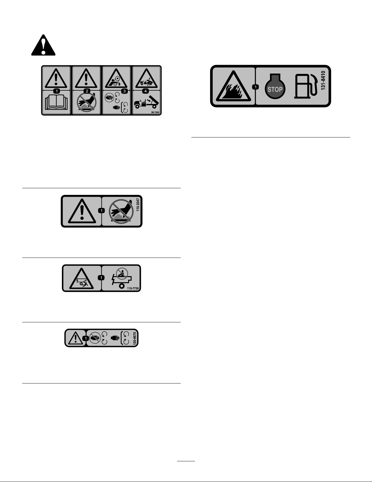
131-8413
CarburetorModelsOnly
1.Horn4.Engine—start
2.Off5.Tostarttheengine:1)Sit
intheoperator'sposition;
2)Disengagetheparking
brake;3)Turnthekeyto
theengineSTARTposition;
4)Engagethechoke;5)
Pressdownonthepedal.
3.On6.Toshutofftheengine:
1)Releasethepedal;2)
Engagetheparkingbrake;
3)TurnthekeytotheOFF
position;4)Removethe
key.
decal131-8413
1.Warning—readthe
Operator'sManual.
131-8414
3.Tippinghazard—drive
slowlyacrossorupslopes;
decal131-8414
taketurnsslowly;donot
exceedspeedsof25kph
(16mph);driveslowly
whenhaulingcargo;drive
slowlyonuneventerrain.
2.Warning—receiveproper
trainingbeforeoperating
themachine.
4.Fallinghazard;severing
hazardoflimbs—donot
carrypassengersinthe
bed;donotcarryextra
passengersinbetween
theseats;donotputyour
armsorlegsoutsideofthe
machinewhileoperating.
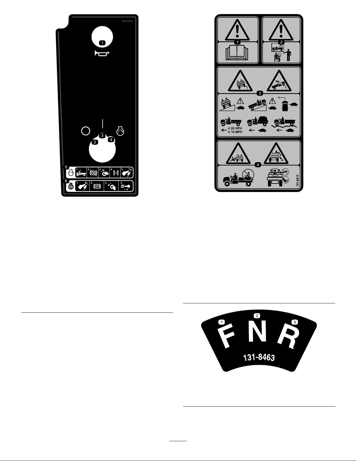
1.Forward3.Reverse
2.Neutral
6
decal131-8463
131-8463
Page 7
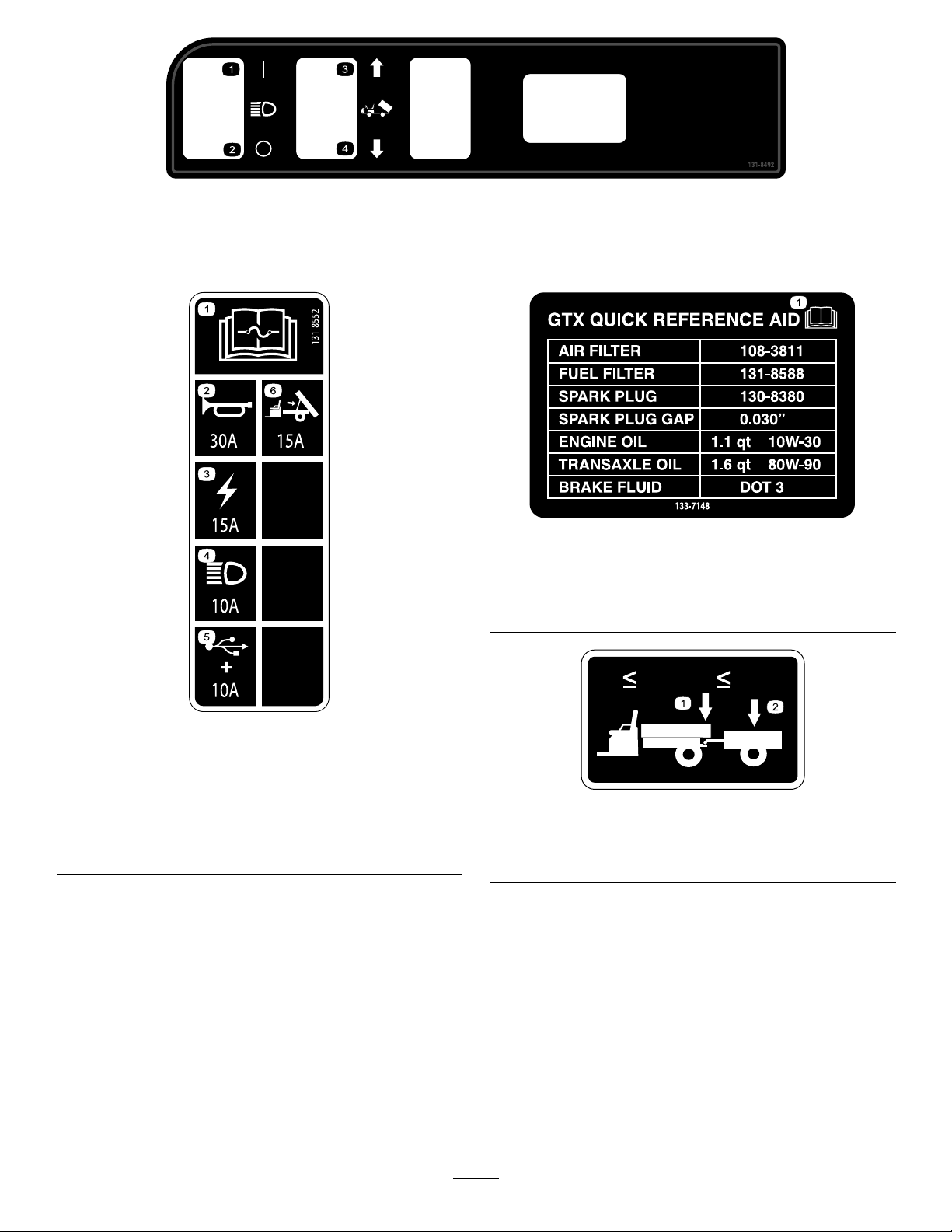
131-8492
200 LBS
91 KG
1500 LBS
680 KG
137-9984
1.Headlight—on3.Raisethebed.
2.Headlight—off
4.Lowerthebed.
1.ReadtheOperator’sManualformoreinformationon
servicingthemachine.
decal131-8492
decal133-7148
133-7148
CarburetorModelsOnly
131-8552
1.ReadtheOperator's
Manualforfuse
information.
2.Horn(30A)5.USBpowerpoint/options
3.Mainpower(15A)6.Optionalliftkit(15A)
4.Headlights(10A)
(10A)
decal131-8552
decal137-9984
137-9984
1.Donotexceedatongue
weightof91kg(200lb).
2.Donotexceedatransport
loadof680kg(1,500lb).
7
Page 8

138-3528
EFIModelsOnly
decal138-3528
decal138-3397
138-3397
EFIModelsOnly
1.Horn4.Engine—start
2.Off5.Tostarttheengine:1)Sit
intheoperator'sposition;
2)Disengagetheparking
brake;3)Turnthekeyto
theengineSTARTposition;
4)Pressthebrakepedal.
3.On6.Toshutofftheengine:1)
Releasethebrakepedal;
2)Engagetheparking
brake;3)Turnthekey
totheOFFposition;4)
Removethekey .
1.ReadtheOperator’s
5.Sparkplugairgap
Manualbeforeperforming
maintenance.
2.Engineintake/airlter
6.Engineoil
3.Fuellter7.Transmissionuid
4.Sparkplug8.Brakeuid
8
Page 9
Setup
LooseParts
Usethechartbelowtoverifythatallpartshavebeenshipped.
ProcedureDescription
Steeringwheel
Steeringwheelcover
1
2
3
4
Washer(1/2inch)
Dustcover1
Nopartsrequired
Nopartsrequired
Operator'sManual
Engineowner'smanual1
Registrationcard1
PredeliveryInspectionForm1
CerticateofQuality
Key2
Note:Determinetheleftandrightsidesofthe
machinefromthenormaloperatingposition.
1
Qty.
1
1
1
–
–
1
1
4.Securethesteeringwheeltotheshaftwiththe
locknut(1/2inch)andtightenitto18to30N∙m
(13to22ft-lb).
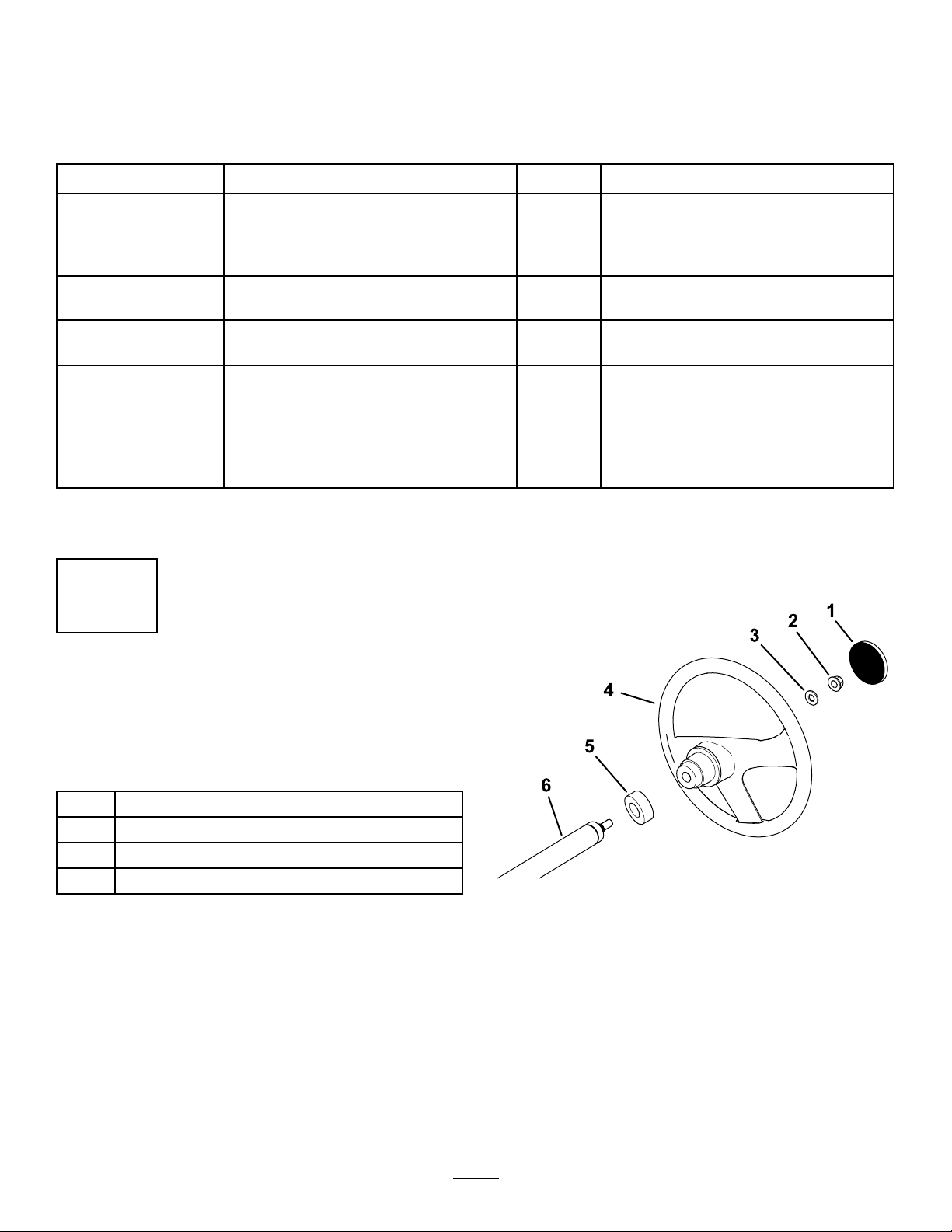
5.Installthecoveronthesteeringwheel(Figure3).
Installthesteeringwheel(International
modelsonly).
Checktheuidlevelsandtirepressure.
Burnish(break-in)thebrakes.
ReadtheOperator'sManualandview
thesetupmaterialbeforeoperatingthe
machine.
Use
InstallingtheSteering Wheel(InternationalModels Only)
Partsneededforthisprocedure:
1
Steeringwheel
1
Steeringwheelcover
1
Washer(1/2inch)
1Dustcover
Procedure
1.Ifthecoverisinstalled,removeitfromthehub
ofthesteeringwheel(Figure3).
2.Removethelocknut(1/2inch)fromthesteering
shaft(Figure3).
3.Slidethesteeringwheel,dustcover,andwasher
(1/2inch)ontothesteeringshaft(Figure3).
Note:Withthefrontwheelsstraight,orientthe
steeringwheelsothatthesmallerspokeonthe
steeringwheelisvertical.
Figure3
1.Steeringwheelcover4.Steeringwheel
2.Locknut(1/2inch)
3.Washer(1/2inch)6.Steeringshaft
5.Dustcover
g198932
9
Page 10

2
4
CheckingtheFluidLevels
andTirePressure
NoPartsRequired
Procedure
1.Checktheengine-oillevelbeforeandafter
yourststarttheengine;refertoCheckingthe
Engine-OilLevel(page37).
2.Checkthebrake-uidlevelbeforeyourststart
theengine;refertoCheckingtheBrake-Fluid
Level(page51).
3.Checkthetransaxle-uidlevelbeforeyou
rststarttheengine;refertoCheckingthe
Transaxle-FluidLevel(page47).
4.Checktheairpressureinthetires;referto
CheckingtheTirePressure(page16).
ReadingtheManualand ViewingtheSetupMaterial
Partsneededforthisprocedure:
1
Operator'sManual
1Engineowner'smanual
1Registrationcard
1PredeliveryInspectionForm
1
CerticateofQuality
2Key
Procedure
•ReadtheOperator'sManualandtheengine
owners'smanual.
•Fillouttheregistrationcard.
•CompletethePredeliveryInspectionForm.
•ReviewtheCerticateofQuality.
3
BurnishingtheBrakes
NoPartsRequired
Procedure
Toensureoptimumperformanceofthebrakesystem,
burnish(break-in)thebrakesbeforeuse.
1.Bringthemachineuptofullspeed,applythe
brakestorapidlystopthemachinewithout
lockingupthetires.
2.Repeatthisprocedure10times,waiting1minute
betweenstops,toavoidoverheatingthebrakes.
Important:Thisprocedureismosteffective
ifthemachineisloadedwith227kg(500lb).
10
Page 11
ProductOverview
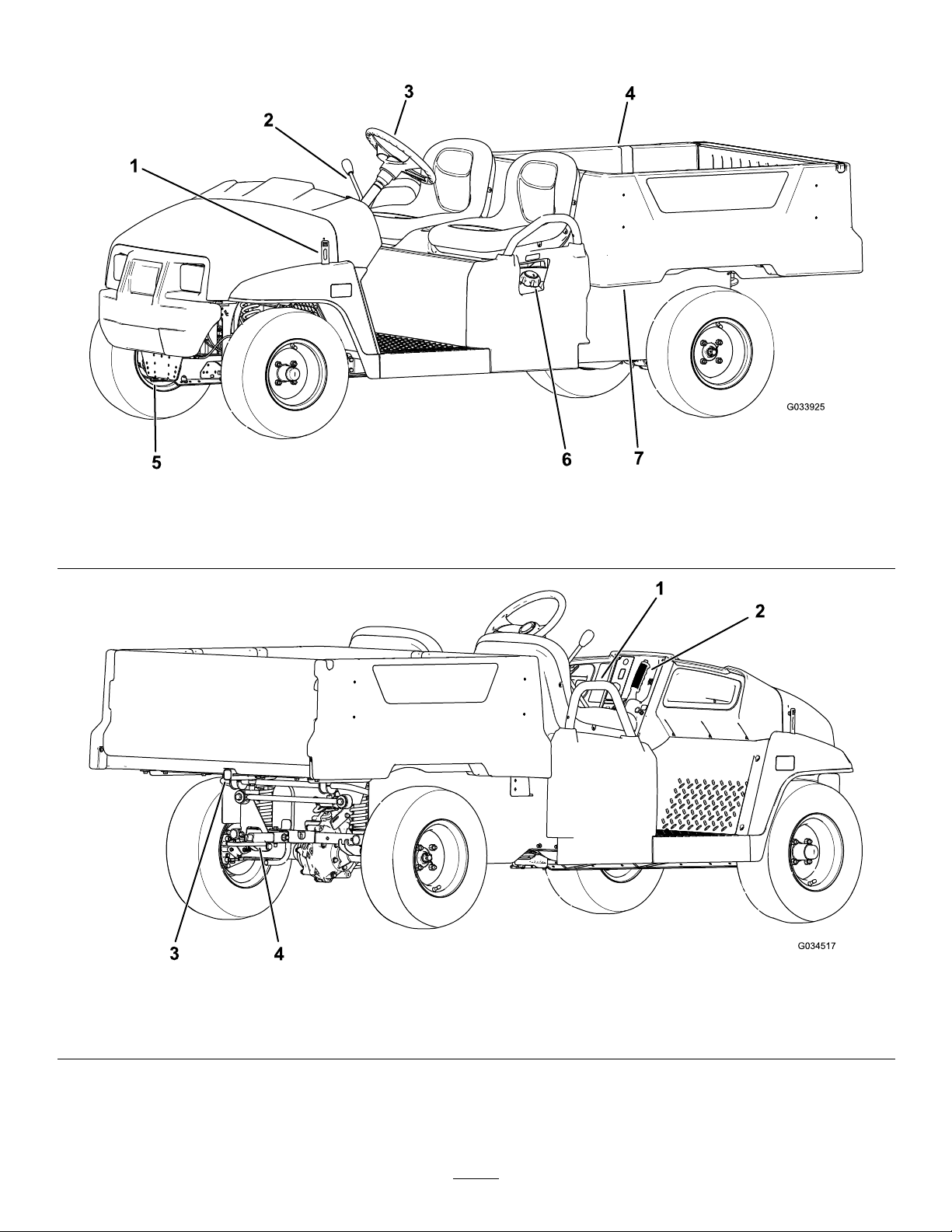
g033925
Figure4
1.Hoodlatch
2.Shiftlever4.Cargobed
3.Steeringwheel
Figure5
5.Towingtongue
6.Fuelcap
7.Cargo-bedlever
g034517
1.Passengerhandhold3.Rearcargo-bed-accessorymount
2.Parking-brakelever4.Trailerhitch
11
Page 12
Controls
Becomefamiliarwithallthecontrolsbeforeyoustarttheengineandoperatethemachine.
Note:Determinetheleftandrightsidesofthemachinefromthenormaloperatingposition.
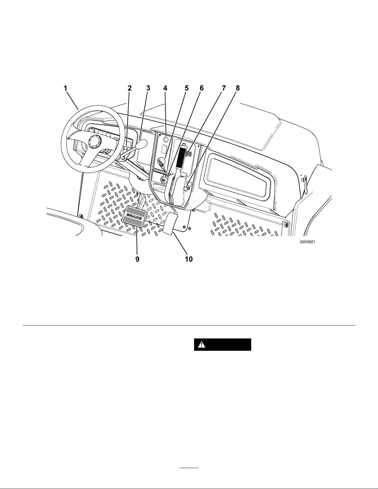
ControlPanel
Figure6
1.Steeringwheel6.USBpowerpoint
2.Gear-shiftindicator
3.Gear-shiftlever8.Chokecontrol
4.Hornbutton(Internationalmodelsonly)
5.Keyswitch10.Acceleratorpedal
AcceleratorPedal
Usetheacceleratorpedal(Figure6)tovarythe
groundspeedofthemachine.Pressingdownthe
acceleratorpedalstartstheengine.Pressingthe
pedalfartherincreasesthegroundspeed.Releasing
thepedalslowsthemachine,andtheengineshutsoff.
Note:Themaximumforwardspeedis26km/h
(16mph).
7.Parking-brakelever
9.Brakepedal
CAUTION
Operatingamachinewithwornorincorrectly
adjustedbrakescanmayresultinpersonal
injury.
Ifthebrakepedaltravelstowithin25mm(1
inch)ofthemachineoorboard,adjustor
repairthebrakes.
BrakePedal
g033921
Usethebrakepedaltostoporslowthemachine
(Figure6).
12
Page 13
KeySwitch
ChokeControl
Thekeyswitchislocatedatthelower,rightcornerof
thedashpanel(Figure6).
Thekeyswitchhas3positions:OFF,ON,andSTART.
Thereare2modesofstartingthemachine;referto
StartingtheEngine(page23).
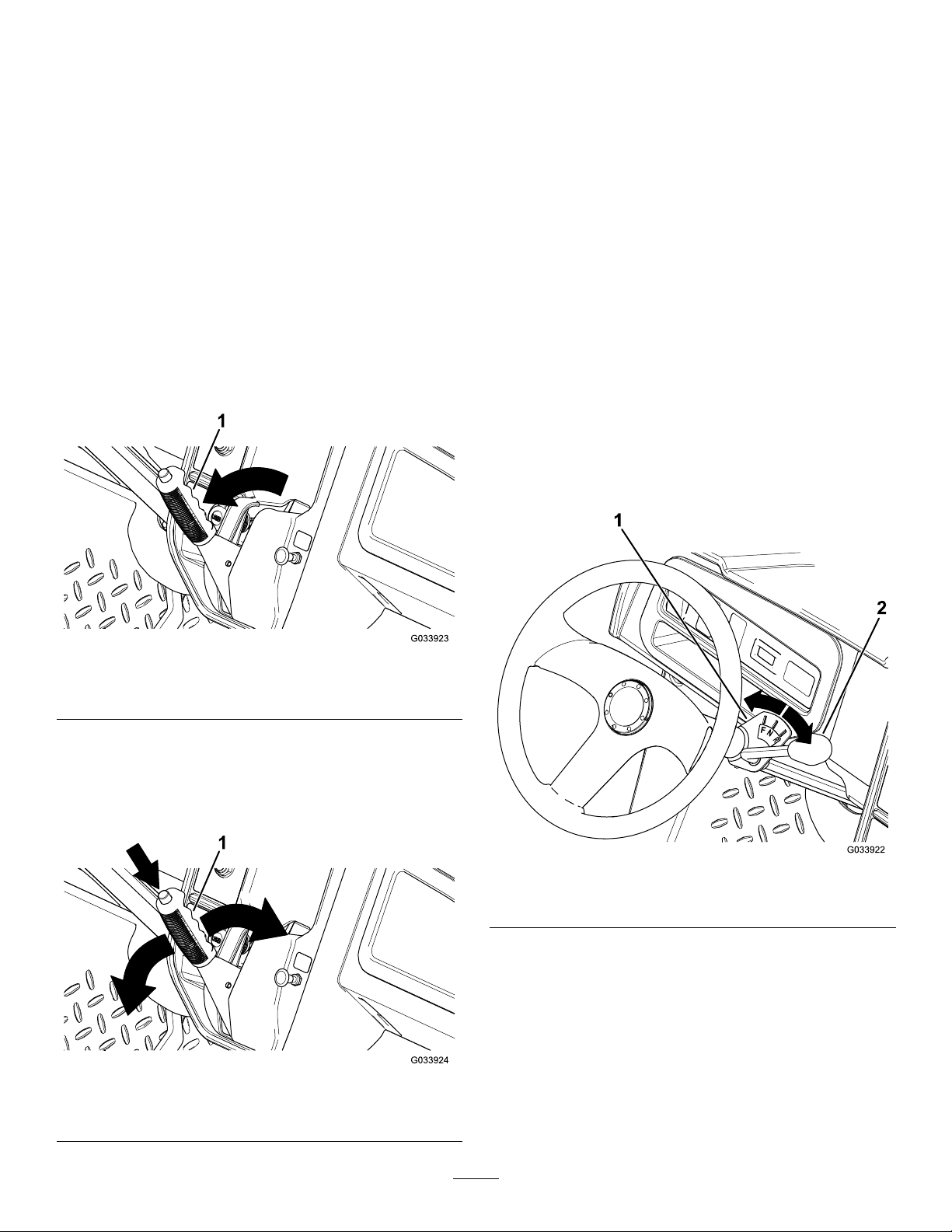
Parking-BrakeLever
Theparking-brakeleverislocatedonthecontrol
panel(Figure6).
Wheneveryoushutofftheengine,engagetheparking
braketopreventthemachinefromaccidentally
moving.Ifthemachineisparkedonasteepgrade,
ensurethatyouengagetheparkingbrake.
Toengagetheparkingbrake,pulltheparking-brake
levertowardyou(Figure7).
Thechokecontrolislocatedonthecontrolpanel.Use
thechoketohelpstartacoldenginebypullingthe
chokecontroloutward(Figure6).Aftertheengine
starts,adjustthechoketokeeptheenginerunning
smoothly.Astheenginewarmsup,pushinthechoke
controltotheOFFposition.
Gear-ShiftLeverandGear-Shift
Indicator
Thegear-shiftlevercanbesetto3positionson
thegear-shiftindicator:FORWARD,REVERSE,and
NEUTRAL(Figure9).
Note:Theenginestartsandrunsinanyofthe3
positions.
FromtheNEUTRALposition,youcanmovethe
gear-shiftleverlefttotheFORWARDpositionorright
totheREVERSEposition(Figure9).
Important:Alwaysstopthemachinebefore
changinggears.
Figure7
1.Parking-brakelever
Todisengagetheparkingbrake,pushdownthe
buttonontopoftheparking-brakelever,pullthe
parking-brakelevertowardyoutoreleasepressure,
andthenpushtheparking-brakeleverforward(Figure
8).
Figure8
g033923
g033922
Figure9
1.Gear-shiftindicator2.Gear-shiftlever
HornButton
InternationalModelsOnly
Thehornbuttonislocatedonthecontrolpanel(Figure
6).Pressthehornbuttontosoundthehorn.
g033924
1.Parking-brakelever
13
Page 14
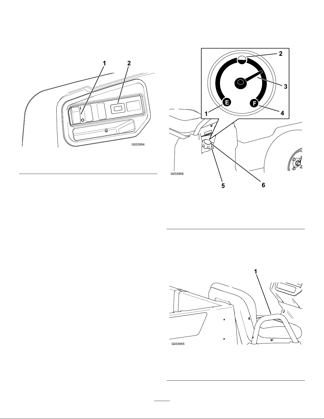
LightSwitch
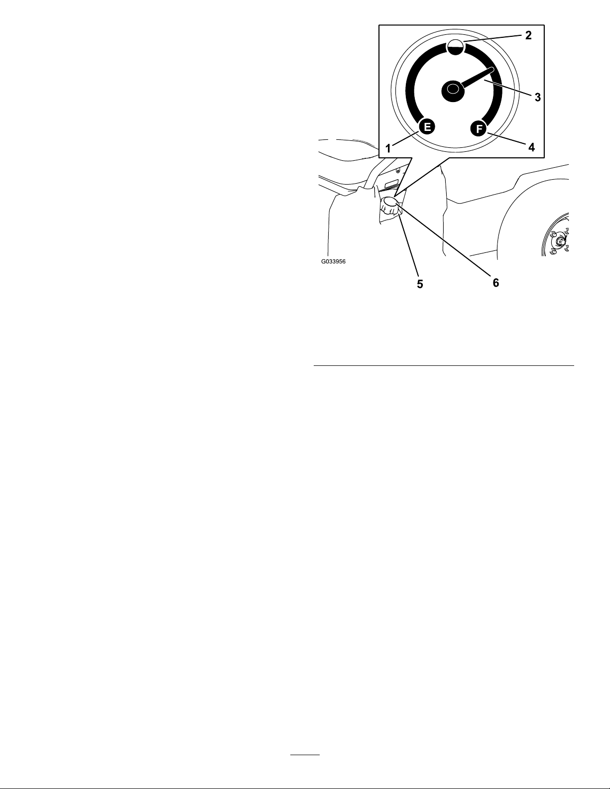
FuelGauge
Thelightswitchislocatedtotheleftofthesteering
column(Figure10).Usethelightswitchtoilluminate
theheadlights.Pushthelightswitchuptoturnonthe
headlights.Pushthelightswitchdowntoturnoffthe
lights.
Figure10
1.Lightswitch2.Hourmeter
Thefuelgauge(Figure11)islocatedonthefueltank
inthellercap,attheleftsideofthemachine.The
gaugedisplaystheamountoffuelinthetank.
g033954
HourMeter
Thehourmeterislocatedtotherightofthelight
switch(Figure10).Usethehourmetertondoutthe
totalnumberofenginehours.Thehourmeterstartsto
functionwheneveryouturnthekeyswitchtotheON
position,ST ARTposition,oriftheengineisrunning.
Note:Whenthemachineisrunning,thehourmeter
blinkscontinuously,recordingusage.
USBPowerPoint
TheUSBpowerpointislocatedtotheleftofthe
parking-brakelever(Figure6).Usethepowerpoint
topowermobiledevices.
Important:WhenyouarenotusingtheUSB
powerpoint,inserttherubberplugtoprevent
damagetothepowerpoint.
Figure11
1.Empty4.Full
2.Halffull
3.Needle6.Fuelgauge
5.Fuel-tankcap
PassengerHandholds
Thepassengerhandholdsarelocatedontheoutside
ofeachseat(Figure12).
g033956
g033955
Figure12
PassengerSideShown
1.Passengerhandhold
14
Page 15

Specications
Note:Specicationsanddesignaresubjecttochangewithoutnotice.
Baseweight
Ratedcapacity(onlevelground)
Maximumgrossvehicleweight(GVW)—onlevelground941kg(2,075lb)total,includingalloftheweightslistedabove
Maximumcargocapacity(onlevelground)363kg(800lb)total,includingrear-mountedaccessories
Maximumrearcargo-bed-accessorymountcapacity
Towcapacity
Overallwidth119cm(47inches)
Overalllength302cm(119inches)
Overallheight127.5cm(50.2inches)
Groundclearance
Wheelbase
Wheeltread(centerlinetocenterline)
Cargobedlength
Cargobedwidth
Cargobedheight28cm(11inches)inside
Enginespeed
397kg(875lb)
544kg(1,200lb)total,including90.7kg(200lb)operatorand91
kg(200lb)passenger,load,accessories,andattachments
45kg(100lb)total
Tongueweight:91kg(200lb)
Maximumtrailerweight:680kg(1,500lb)
21.6cm(8.5inches)atthefrontwithnoloadoroperator
14cm(5.5inches)attherearwithnoloadoroperator
220cm(86.6inches)
Front:119cm(47inches)
Rear:119cm(47inches)
Inside:102cm(40inches)
Outside:1 14.3cm(45inches)
Inside:98cm(38.5inches)
Outsideofthemoldedfenders:107.3cm(42.25inches)
Lowidle:1,250to1,350rpm
Highidle:3,650to3,750rpm
Attachments/Accessories
AselectionofToroapprovedattachmentsandaccessoriesisavailableforusewiththemachinetoenhance
andexpanditscapabilities.ContactyourAuthorizedServiceDealerorDistributororgotowww.Toro.comfora
listofallapprovedattachmentsandaccessories.
15
Page 16
Operation
Note:Determinetheleftandrightsidesofthe
machinefromthenormaloperatingposition.
CheckingtheTirePressure
ServiceInterval:Beforeeachuseordaily
Frontandreartiresairpressurespecication:165
to207kPa(24to30psi)
BeforeOperation
BeforeOperationSafety
GeneralSafety
•Neverallowchildrenoruntrainedpeopleto
operateorservicethemachine.Localregulations
mayrestricttheageoftheoperator.Theowner
isresponsiblefortrainingalloperatorsand
mechanics.
•Becomefamiliarwiththesafeoperationofthe
equipment,operatorcontrols,andsafetysigns.
•Knowhowtostopthemachineandshutoffthe
enginequickly.
•Ensurethatyouandyourpassengersdonot
exceedthenumberofhandholdsequippedonthe
machine.
•Checkthatallsafetydevicesanddecalsarein
place.Repairorreplaceallsafetydevicesand
replaceallillegibleormissingdecals.Donot
operatethemachineunlesstheyarepresentand
functioningproperly.
Important:Donotexceedthemaximumair
pressureindicatedonthesidewallofthetire.
Note:Theairpressureneededinthetiresis
determinedbythepayloadthatyouintendtocarry.
1.Checktheairpressureinthetires.
•Uselowerairpressureinthetiresforlighter
payloads,forlesssoilcompaction,fora
smootherride,andtominimizetiremarkson
theground.
•Usehigherairpressureinthetiresfor
carryingheavierpayloadsathigherspeeds.
2.Ifnecessary ,adjusttheairpressureinthetires
byaddingorremovingairinthetires.
FuelSafety
•Useextremecareinhandlingfuel.Itisammable
anditsvaporsareexplosive.
•Extinguishallcigarettes,cigars,pipes,andother
sourcesofignition.
•Useonlyanapprovedfuelcontainer.
•Donotremovethefuelcaporllthefueltank
whiletheengineisrunningorhot.
•Donotaddordrainfuelinanenclosedspace.
•Donotstorethemachineorfuelcontainerwhere
thereisanopename,spark,orpilotlight,such
asonawaterheaterorotherappliance.
•Ifyouspillfuel,donotattempttostarttheengine;
avoidcreatinganysourceofignitionuntilthefuel
vaporshavedissipated.
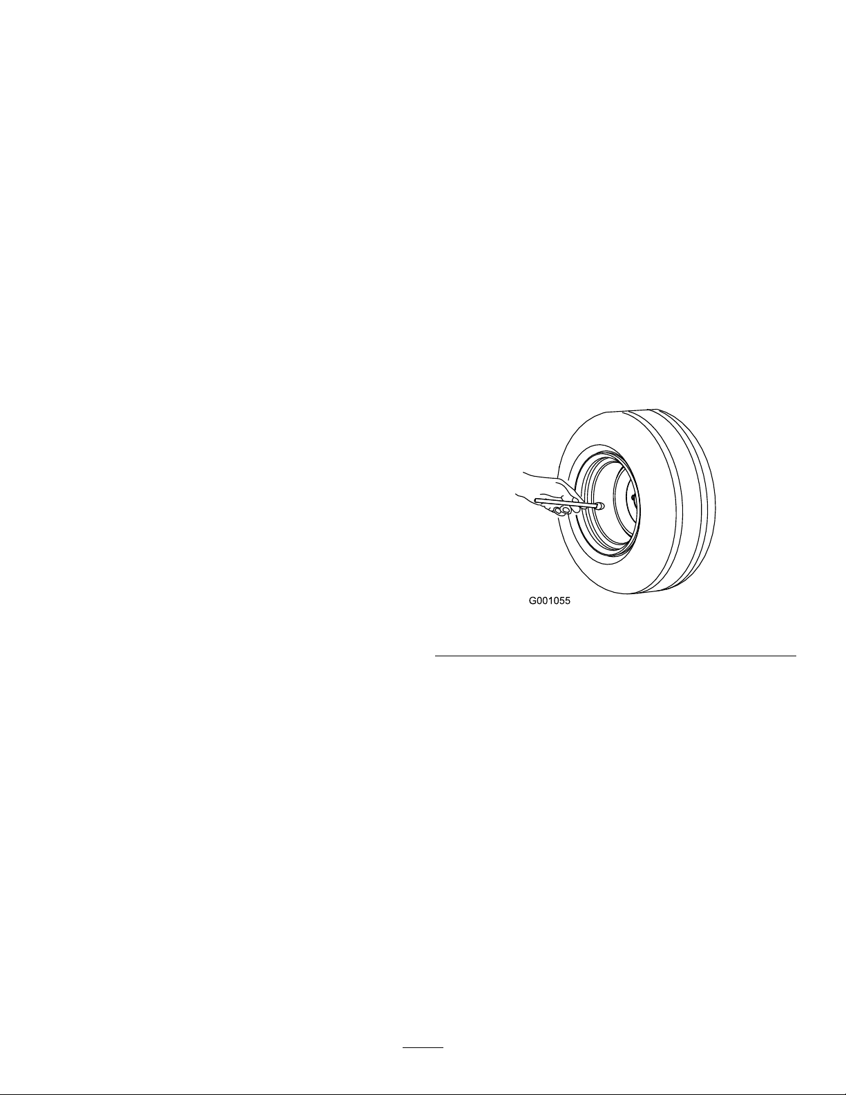
PerformingDaily Maintenance
Beforestartingthemachineeachday ,performthe
EachUse/DailyprocedureslistedinMaintenance
(page26).
g001055
Figure13
16
Page 17
AddingFuel
RecommendedFuel
•Forbestresults,useonlyclean,fresh(lessthan
30daysold),unleadedgasolinewithacetane
ratingof87orhigher((R+M)/2ratingmethod).
•Ethanol:Gasolinewithupto10%ethanol
(gasohol)or15%MTBE(methyltertiarybutyl
ether)byvolumeisacceptable.Ethanoland
MTBEarenotthesame.Gasolinewith15%
ethanol(E15)byvolumeisnotapprovedforuse.
Neverusegasolinethatcontainsmorethan
10%ethanolbyvolume,suchasE15(contains
15%ethanol),E20(contains20%ethanol),orE85
(containsupto85%ethanol).Usingunapproved
gasolinemaycauseperformanceproblemsand/or
enginedamagewhichmaynotbecoveredunder
warranty.
•Donotusegasolinecontainingmethanol.
•Donotstorefueleitherinthefueltankorfuel
containersoverthewinterunlessafuelstabilizer
isused.
•Donotaddoiltogasoline.
Figure14
1.Empty4.Full
2.Halffull
3.Needle6.Fuelgauge
5.Fuel-tankcap
g033956
FillingtheFuelTank
Thefuel-tankcapacityisapproximately18.9L(5US
gallons).
1.Parkthemachineonalevelsurface.
2.Engagetheparkingbrake.
3.Shutofftheengineandremovethekey.
4.Cleantheareaaroundthefuel-tankcap(Figure
14).
5.Removethefuel-tankcap.
6.Fillthetanktoabout25mm(1inch)belowthe
topoftank(bottomofthellerneck).
Note:Thisspaceinthetankallowsfuelto
expand.Donotoverllthefueltank.
7.Installthefuel-tankcapsecurely.
8.Wipeupanyspilledfuel.
BreakinginaNewMachine
ServiceInterval:Aftertherst100hours—Perform
theguidelinesforbreakinginanew
machine.
Performthefollowingguidelinestoprovideproper
performanceforthemachine.
•Ensurethatthebrakesareburnished;referto3
BurnishingtheBrakes(page10).
•Checktheuidandengine-oillevelsregularly.
Remainalertforsignsthatthemachineorits
componentsareoverheating.
•Afterstartingacoldengine,letitwarmupforabout
15secondsbeforeusingthemachine.
Note:Allowmoretimefortheenginetowarmup
whenoperatingincoldtemperatures.
•Varythemachinespeedduringoperation.Avoid
faststartsandquickstops.
17
Page 18

•Abreak-inoilfortheengineisnotrequired.
Originalengineoilisthesametypespeciedfor
regularoilchanges.
•RefertoMaintenance(page26)foranyspecial,
low-hourchecks.
•Checkthefrontsuspensionpositioningandadjust
it,ifnecessary;refertoAdjustingtheFrontWheel
Toe-in(page46).
DuringOperation
DuringOperationSafety
GeneralSafety
•Theowner/operatorcanpreventandisresponsible
foraccidentsthatmaycausepersonalinjuryor
propertydamage.
•Passengersshouldsitinthedesignatedseating
positionsonly.Donotcarrypassengersinthe
cargobed.Keepbystandersandpetsawayfrom
themachineduringoperation.
•Wearappropriateclothing,includingeye
protection;longpants;substantial,slip-resistant
footwear;andhearingprotection.Tiebacklong
hairanddonotwearloosejewelry .
•Donotoperatethemachinewhileill,tired,or
undertheinuenceofalcoholordrugs.
•Operatethemachineoutdoorsorina
well-ventilatedareaonly.
•Donotexceedthemaximumgrossvehicleweight
(GVW)ofthemachine.
•Useextracautionwhenoperatingthemachine
withaheavyloadinthecargobed.Theheavier
theload,themoredifcultitistoturnorstop.
•Carryingoversizedloadsinthecargobedreduces
thestabilityofthemachine.
•Carryingmaterialthatcannotbeboundtothe
machine,suchasalargetankofliquid,adversely
affectsthesteering,braking,andstabilityofthe
machine.
•Beforeyoustarttheengine,ensurethatthe
transmissionisinneutral,theparkingbrakeis
engaged,andyouareintheoperatingposition.
•Youandyourpassengersshouldremainseated
wheneverthemachineismoving.Keepyour
handsonthesteeringwheel;yourpassengers
shouldusethehandholdsprovided.Keepyour
armsandlegswithinthemachinebodyatalltimes.
•Operatethemachineonlyingoodvisibility.
Watchforholes,ruts,bumps,rocks,orother
hiddenobjects.Uneventerraincouldoverturnthe
machine.Tallgrasscanhideobstacles.Usecare
whenapproachingblindcorners,shrubs,trees,or
otherobjectsthatmayobscureyourvision.
•Alwayswatchoutforandavoidlowoverhangs
suchastreelimbs,doorjambs,overhead
walkways,etc.
•Lookbehindanddownbeforereversingthe
machinetobesureofaclearpath.
•Donotdrivethemachineneardrop-offs,ditches,
orembankments.Themachinecouldsuddenly
rolloverifawheelgoesovertheedgeorifthe
edgegivesway.
•Whenusingthemachineonpublicroads,follow
alltrafcregulationsanduseanyadditional
accessoriesthatmayberequiredbylaw,suchas
lights,turnsignals,slow-movingvehicle(SMV)
signs,andothersasrequired.
•Ifthemachineevervibratesabnormally,stopthe
machineimmediately,shutofftheengine,remove
thekey,waitforallmovementtostop,andinspect
fordamage.Repairalldamagetothemachine
beforeresumingoperation.
•Carryareducedloadandreducetheground
speedofthemachinewhenoperatingonrough,
uneventerrain,andnearcurbs,holes,andother
suddenchangesinterrain.Loadsmayshift,
causingthemachinetobecomeunstable.
•Itcantakelongertostopthemachineonwet
surfacesthanondrysurfaces.T odryoutwet
brakes,driveslowlyonlevelgroundwhileputting
lightpressureonthebrakepedal.
•Suddenchangesinterrainmaymovethesteering
wheelunexpectedly,whichcouldresultinhand
andarminjuries.Reduceyourspeedandgrip
thesteeringwheellooselyaroundtheperimeter,
keepingyourthumbsoutofthewayofthesteering
wheelspokes.
•Reducethespeedwhenyouoperatethemachine
withthecargobedremoved.Operatingthe
machineathighspeedandthenquicklystopping
maycausetherearwheelstolockup,which
impairsyourcontrolofthemachine.
•Donottouchtheengine,transmission,mufer,or
mufermanifoldwhiletheengineisrunning,or
soonafteryoushutofftheengine,becausethese
areasmaybehotenoughtocauseburns.
•Donotleavearunningmachineunattended.
•Beforeleavingtheoperatingposition,dothe
following:
–Parkthemachineonlevelground.
–Engagetheparkingbrake.
–Lowerthecargobed.
–Shutofftheengineandremovethekey .
18
Page 19

•Donotoperatethemachinewhenthereistherisk
oflightning.
•Useaccessoriesandattachmentsapprovedby
TheT oro®Companyonly .
Multi-PassengerSafety
•Heavyloadsaffectstabilityonaslope.Carrya
reducedloadandreduceyourgroundspeedwhen
operatingonaslopeoriftheloadhasahigh
centerofgravity.Securetheloadtothecargobed
ofthemachinetopreventtheloadfromshifting.
Takeextracarewhenhaulingloadsthatshifteasily
(e.g.,liquids,rock,sand,etc.).
•Youmustaccountfortheextrapassengers
contributingtotheoverallgrossvehicleweight
(GVW)ofthemachine.
•Ifyouhavealoadinthecargobed,ensurethat
youdonotexceedthecapacityofthemachineby
havingtoomanypassengers.
•Passengersshouldsitinthedesignatedseating
positionsonly.Donotallowpassengerstositin
thecargobed.
•Youandyourpassengersshouldremainseated
wheneverthemachineisinmotion.
•Theadditionalmachinelengthresultsinalarger
turnradius,soallowmorespacetomaneuverthe
machine.
SlopeSafety
Note:A2-postRolloverProtectionSystem(ROPS)
isavailableforthismachineasanaccessory.Usea
ROPSifyouwillworknexttodrop-offs,nearwater,
inroughterrain,oronaslope,whichcouldresultin
arollover.ContactanauthorizedTorodistributorfor
moreinformation.
•Avoidstarting,stopping,orturningthemachine
onaslope,especiallywithaload.Stoppingwhile
goingdownaslopetakeslongerthanstopping
onlevelground.Ifyoumuststopthemachine,
avoidsuddenspeedchanges,whichcancause
themachinetotiporrollover.Donotengagethe
brakessuddenlywhenrollingrearward,asthis
maycausethemachinetooverturn.
LoadingandDumpingSafety
•Donotexceedthegrossvehicleweight(GVW)
ofthemachinewhenoperatingitwithaloadin
thecargobedand/ortowingatrailer;referto
Specications(page15).
•Distributetheloadinthecargobedevenlyto
improvethestabilityandcontrolofthemachine.
•Beforedumping,ensurethatthereisnoone
behindthemachine.
•Donotdumpaloadedcargobedwhilethe
machineissidewaysonaslope.Thechange
inweightdistributionmaycausethemachineto
overturn.
Slopesareamajorfactorrelatedtoloss-of-control
andtip-overaccidents,whichcanresultinsevere
injuryordeath.
•Surveythesitetodeterminewhichslopesare
safeforoperatingthemachineandestablishyour
ownproceduresandrulesforoperatingonthose
slopes.Alwaysusecommonsenseandgood
judgmentwhenperformingthissurvey.
•Ifyoufeeluneasyoperatingthemachineona
slope,donotdoit.
•Keepallmovementonslopesslowandgradual.
Donotsuddenlychangethespeedordirectionof
themachine.
•Avoidoperatingthemachineonwetterrain.Tires
maylosetraction.Arollovercanoccurbeforethe
tireslosetraction.
•Travelstraightupanddownaslope.
•Ifyoubegintolosemomentumwhileclimbinga
slope,graduallyengagethebrakesandslowly
reversethemachinestraightdowntheslope.
•Turningwhilegoingupordownaslopecanbe
dangerous.Ifyoumustturnonaslope,doitslowly
andcautiously.
19
Page 20

OperatingtheCargoBed
RaisingtheCargoBedtothe DumpPosition
WARNING
Araisedbedcouldfallandinjurepersonsthat
areworkingbeneathit.
•Alwaysusetheproprodtoholdthebedup
beforeworkingunderthebed.
•Removeanyloadmaterialfromthebed
beforeraisingit.
WARNING
Drivingthemachinewiththecargobedraised
couldcausethemachinetotiporrolleasier.
Youcoulddamagethestructureofthecargo
bedifyouoperatethemachinewiththebed
raised.
•Operatethemachinewhenthecargobed
isdown.
•Afteremptyingthecargobed,lowerit.
CAUTION
Ifaloadisconcentratednearthebackofthe
cargobedwhenyoureleasethelatches,the
bedmayunexpectedlytipopen,injuringyou
orbystanders.
Figure15
1.Cargo-bedlever
2.Pulltheproprodintothedumppositiondetent
slottosecurethebedfordumping(Figure16).
Figure16
1.Servicepositiondetent
slot
2.Proprod
3.Dumppositiondetentslot
g034019
g034021
•Centerloadsinthecargobed,ifpossible.
•Holdthecargobeddownandensurethat
nooneisleaningoverthebedorstanding
behinditwhenreleasingthelatches.
•Removeallcargofromthebedbefore
liftingthebeduptoservicethemachine.
1.Pulltheleveronleft,insideofthecargobed
towardyouandliftthecargobedup(Figure15).
20
Page 21

RaisingtheCargoBedtothe
OpeningtheTailgate
ServicePosition
1.Pulltheleveronleft,insideofthecargobed
towardyouandliftthecargobedup(Figure15).
2.Pullproprodintotheservicepositiondetentslot
tosecurethebedformaintenance(Figure16).
LoweringtheCargoBed
WARNING
Theweightofthebedmaybeheavy.Hands
orotherbodypartscouldbecrushed.
Keepyourhandsandotherbodypartsaway
whenloweringthebed.
1.Raisethecargobedslightlybyliftinguponthe
latchlever(Figure15).
2.Pulltheproprodoutofthedetentslot(Figure
16).
3.Lowerthebeduntilitlatchessecurely.
1.Ensurethatthecargobedisdownandlatched.
2.Usingbothhands,raisethetailgateusingthe
ridgenearthetopofthetailgate(Figure17).
3.Lowerthetailgateuntilitisushwiththebottom
ofthecargobed(Figure17).
Figure17
g034022
21
Page 22

ClosingtheTailgate
UsingtheRearCargoBed
Ifyouunloadedloosematerialsuchassand,
landscapingrock,orwoodchipsfromthecargobedof
themachine,someofthematerialthatyouunloaded
mayhavelodgedinthehingeareaofthetailgate.
Performthefollowingstepsbeforeclosingthetailgate.
1.Useyourhandstoremoveasmuchofthe
materialfromthehingeareaaspossible.
2.Rotatethetailgatetoapproximatelythe45°
position(Figure18).
Figure18
AccessoryMount
Usetherearcargobedaccessorymounttoattach
accessoriestotherearofthemachine.
Capacity:45kg(100lb)
1.Loosenthe“T”handlebyrotatingitclockwise
(Figure19).
g034525
Figure19
g034023
1.Receiver
2.“T”handle
1.Rotatethetailgateback
andforthseveraltimes.
2.Rotatethetailgateto
approximatelythe45°
position.
3.Hingearea
3.Useashort,shakingmotiontorotatethetailgate
backandforthseveraltimes(Figure18).
Note:Thisactionhelpsmovematerialaway
fromthehingearea.
4.Lowerthetailgateandcheckformaterial
remaininginthehingearea.
5.Repeatsteps1through4untilthematerialis
removedfromthehingearea.
6.Rotatethetailgateupandliftthetailgateintothe
notchesinthecargobed.
2.Insertyouraccessoryintothereceiveruntilthe
holesalign(Figure19).
3.Securetheassembledaccessorytothereceiver
tubeusingtheclevispinandhairpincotter
suppliedwiththeaccessory .
4.Tightenthe“T”handlebyrotatingit
counterclockwise(Figure20).
g034526
Figure20
1.“T”handle
22
Page 23

LoadingtheCargoBed
Usethefollowingguidelineswhenloadingthecargo
bedandoperatingthemachine:
•Observetheweightcapacityofthemachineand
limittheweightoftheloadthatyoucarryinthe
cargobedasdescribedinSpecications(page
15)andonthegrossvehicleweighttagofthe
machine.
Note:Theloadratingisspeciedformachine
operationonalevelsurfaceonly.
•Reducetheweightoftheloadthatyoucarryinthe
cargobedwhenoperatingthemachineonhills
androughterrain.
•Reducetheweightoftheloadthatyoucarrywhen
thematerialsaretall(andhaveahighcenterof
gravity),suchasastackofbricks,landscaping
timbers,orfertilizerbags.Distributetheloadas
lowaspossibletoensurethattheloaddoesnot
reduceyourabilitytoseebehindthemachine
whenoperatingit.
•Keeploadscenteredbyloadingthecargobedas
follows:
–Evenlypositiontheweightinthecargobed
fromsidetoside.
Important:Tippingoverismorelikelyto
occurifthecargobedisloadedto1side.
–Evenlypositiontheweightinthecargobed
fromfronttoback.
Important:Lossofsteeringcontrolorthe
machinemaytipoverifyoupositionthe
loadbehindtherearaxleandthetraction
onthefronttiresisreduced.
Refertothefollowingtableforloadvolumelimitswith
variousmaterials:
MaterialDensity
Gravel,dry1522kg/m
Gravel,wet1922kg/m
Sand,dry1442kg/m
Sand,wet1922kg/m
Wood
Bark
Earth,packed
721kg/m
3
(95
3
lb/ft
)
3
(120
3
lb/ft
)
3
(90
3
lb/ft
)
3
(120
3
lb/ft
)
3
(45lb/ft
<721kg/m
1602kg/m
3
(<45
3
lb/ft
)
3
(100
3
lb/ft
)
MaximumCargo
BedCapacity
(onlevelground)
Full
3/4Full
Full
3/4full
3
)
Full
Full
3/4Full
(approximately)
StartingtheEngine
1.Sitintheoperatorseat,insertthekeyintothe
keyswitch,androtatethekeyclockwisetothe
ONorSTARTposition.
Thereare2modesofstartingthemachine:
•PedalStart—turnthekeyswitchtotheON
position,pressdowntheacceleratorpedal,
thenreleaseyourfootfromtheaccelerator
pedal.
Note:Whenyouremoveyourfootfromthe
acceleratorpedal,theengineshutsoff.
•KeyStart—turnthekeyswitchtotheSTART
positionandtheengineremainsonuntilthe
isturnedtotheOFFposition.
•Useextracautionwhentransportingoversized
loadsinthecargobed,particularlywhenyou
cannotcenterthewightoftheoversizeloadtothe
cargobed.
•Wheneverpossible,securetheloadbybindingit
tothecargobedsothatitdoesnotshift.
•Whentransportingliquidinalargetank(such
asasprayertank),usecautionwhendriving
themachineuphillordownhill,whensuddenly
changingspeedorstopping,orwhendrivingover
toughsurfaces.
Thecapacityofthecargobedis0.28m
Theamount(volume)ofmaterialthatyoucanplace
inthebedwithoutexceedingtheloadratingsofthe
machinecanvarygreatlydependingonthedensity
ofthematerial.
3
(10ft3).
Note:Whenusingkeystartmode,youcan
engagetheparkingbrakeandworkawayfrom
themachinewhiletheenginestillrunsandthe
batteryholdsacharge.
Note:IfyouturnthekeytotheSTARTposition,
theenginecranksuntilitstarts.Iftheengine
cranksformorethan10seconds,returntothe
OFFposition,anddeterminetheissue(e.g.,the
chokecontrolsneedstobeengaged,checkthe
aircleanerforrestrictions,ensurethatthefuel
tankisfull,thesparkisbad,etc.)beforestarting
themachineagain.
Note:Whenequippedwiththeoptionalbackup
alarm,ifyoumovethegear-shiftselectortothe
REVERSEpositionwhenthekeyswitchisinthe
ONorSTARTposition,abuzzersoundstowarn
theoperatorthatthemachineisinreversegear.
2.Movethegear-shiftselectortothedesired
directionoftravelforthemachine.
23
Page 24

3.Disengagetheparkingbrake.
4.Slowlystepontheacceleratorpedal.
AfterOperation
Note:Iftheengineiscold,pressandholdthe
acceleratorpedalabouthalf-waydown,andpull
thechokeknobouttotheONposition.Return
thechokeknobtotheOFFpositionafterthe
enginewarmsup.
StoppingtheMachine
Important:Whenstoppingthemachineon
anincline,usetheservicebrakestostopthe
machineandengagetheparkingbraketoholdthe
machineinplace.Usingtheacceleratortostall
themachineonthehillcandamagethemachine.
1.Removeyourfootfromtheacceleratorpedal.
2.Slowlypressthebrakepedaltoapplytheservice
brakesuntilthemachinecomestoacomplete
stop.
Note:Thestoppingdistancemayvary
dependingonthemachineloadandspeed.
ParkingtheMachine
1.Stopthemachineusingtheservicebrakesby
pressingandholdingthebrakepedal.
2.Engagetheparkingbrakebypullingthe
parking-brakelevertowardyou.
3.RotatethekeycounterclockwisetotheOFF
position.
AfterOperationSafety
GeneralSafety
•Allowtheenginetocoolbeforestoringthemachine
inanyenclosure.
•Donotstorethemachineorfuelcontainerwhere
thereisanopename,spark,orpilotlight,such
asonawaterheaterorotherappliance.
•Keepallpartsofthemachineingoodworking
conditionandallhardwaretightened.
•Replaceallworn,damaged,ormissingdecals.
TransportingtheMachine
•Usecarewhenloadingorunloadingthemachine
intoatraileroratruck.
•Usefull-widthrampsforloadingthemachineinto
atraileroratruck.
•Tiethemachinedownsecurely.
RefertoFigure21andFigure22forthetie-down
locationsonthemachine.
Note:Loadthemachineonthetrailerwiththefront
ofthemachinefacingforward.Ifthatisnotpossible,
securethemachinehoodtotheframewithastrap,
orremovethehoodandtransportandsecureit
separatelyorthehoodmayblowoffduringtransport.
4.Removethekey.
CAUTION
Looseseatsmayfalloffthemachineand
trailerwhentransportingthemachine,and
theseatsmaylandonanothermachineor
obstructtheroadway.
Removetheseatsormakesurethattheseats
aresecurelyfastenedtothecouplinginthe
seatshroud.
24
Page 25

TowingtheMachine
Incaseofanemergency,youcantowthemachine
forashortdistance;however,thisshouldnotbea
standardoperatingprocedure.
WARNING
Towingatexcessivespeedscouldcausea
lossofsteeringcontrol,resultinginpersonal
injury.
Figure21
1.Towingtongueandtie-downpoint(frontofthemachine)
Figure22
1.Reartie-downpoints
g236535
Nevertowthemachineatfasterthan8km/h
(5mph).
Note:Thepowersteeringdoesnotfunction,
makingitdifculttosteer.
Towingthemachineisa2-personjob.Ifyoumust
movethemachineaconsiderabledistance,transport
itonatruckortrailer;refertoT owingaTrailer(page
25)
1.Removethedrivebeltfromthemachine;referto
ReplacingtheDriveBelt(page52).
2.Afxatowlinetothetongueatthefrontofthe
machine’sframe(Figure21).
3.MovethetransmissiontotheNEUTRALposition
anddisengagetheparkingbrake.
g034273
TowingaTrailer
Themachineiscapableofpullingtrailers.Atowhitch
isavailableforthemachine.Contactyourauthorized
Torodistributorfordetails.
Whenhaulingcargoortowingatrailer,donot
overloadyourmachineortrailer.Overloadingeither
themachineorthetrailercancausepoorperformance
ordamagetothebrakes,axle,engine,transaxle,
steering,suspension,bodystructure,ortires.
Alwaysloadatrailerwith60%ofthecargoweightin
thefrontofthetrailer.Thisplacesapproximately10%
ofthegrosstrailerweight(GTW)onthetowhitchof
themachine.
Toprovideadequatebrakingandtraction,alwaysload
thecargobedwhenusingatrailer.Donotexceed
theGTWorGVWlimits.
Avoidparkingamachinewithatraileronahill.Ifyou
mustparkonahill,engagetheparkingbrake,and
chockthetiresofthetrailer.
25
Page 26

Maintenance
Note:Determinetheleftandrightsidesofthemachinefromthenormaloperatingposition.
Note:Downloadacopyoftheelectricalschematicbyvisitingwww.T oro.comandsearchingforyourmachine
fromtheManualslinkonthehomepage.
Important:Refertoyourengineowner’smanualforadditionalmaintenanceprocedures.
WARNING
Failuretoproperlymaintainthemachinecouldresultinprematurefailureofmachinesystems
causingpossibleharmtoyouorbystanders.
Keepthemachinewellmaintainedandingoodworkingorderasindicatedintheseinstructions.
CAUTION
Onlyqualiedandauthorizedpersonnelshouldmaintain,repair,adjust,orinspectthemachine.
•Avoidrehazardsandhavere-protectionequipmentpresentintheworkarea.Donotuse
anopenametocheckuidlevelsorleakageoffuel,batteryelectrolyte,orcoolant.
•Donotuseopenpansoffuelorammablecleaninguidsforcleaningparts.
CAUTION
Ifyouleavethekeyinthekeyswitch,someonecouldaccidentlystarttheengineandseriously
injureyouorotherbystanders.
Removethekeyfromthekeyswitchanddisconnectthewiresfromthesparkplugsbefore
youdoanymaintenance.Setthewiresasidesothattheydonotaccidentallycontactthe
sparkplugs.
26
Page 27

RecommendedMaintenanceSchedule(s)
MaintenanceService
Interval
Aftertherst5hours
Aftertherst8hours
Aftertherst50hours
Aftertherst100hours
Beforeeachuseordaily
Every50hours
Every100hours
MaintenanceProcedure
•Changetheengineoil.
•Checktheconditionofthedrivebelt.
•Checkthetensionofthestarter-generatorbelt.
•Checktheairlterforthecarboncanister.
•Performtheguidelinesforbreakinginanewmachine.
•Checkthetirepressure.
•Checktheengine-oillevel.
•Checkgear-shiftoperation.
•Checkthebrake-uidlevel.
•Removetheair-cleanercoverandcleanoutthedebris.Donotremovethelter.
•Cleanoutthedebrisinthedustcap.
•Greasethebearingsandbushings.
•Replacetheairlter.Replacetheair-lterelementsoonerifdirtyordamaged.
•Servicetheairlter(morefrequentlyinextremedustyordirtyconditions).
•Changetheengineoil.
•Checkthesparkplug.
•Checktheconditionofthetiresandrims.
•Torquethewheellugnuts.
•Checkthefrontwheelcamberandtoe-in.
•Checkthetransaxle-uidlevel.
•Checktheoperationoftheneutralgear-shiftposition.
•Cleantheengine-coolingareas.
•Inspectthebrakes.
Every200hours
Every300hours
Every400hours
Every800hours
Every1,000hours
•Checktheairlterforthecarboncanister.
•Checktheconditionandtensionofthedrivebelt.
•Checkthetensionofthestarter-generatorbelt.
•Greasethefrontwheelbearings.
•Inspectthefuellinesandconnections.
•Replacethefuellter.
•Cleantheprimary-driveclutch.
•Changethetransaxleuid.
•Changethebrakeuid.
Yearly
•Completealloftheyearlymaintenanceproceduresthatarespeciedintheengine
owner'smanual.
27
Page 28

DailyMaintenanceChecklist
Duplicatethispageforroutineuse.
Fortheweekof: MaintenanceCheckItem
Checkthebrakeand
parkingbrakeoperation.
Checkthegear
shift/neutraloperation.
Checkthefuellevel.
Checktheengine-oillevel.
Checkthetransaxle-uid
level.
Inspecttheairlter.
Inspecttheengine-cooling
ns.
Checkforunusualengine
noises.
Checkforunusual
operatingnoises.
Checkthetirepressure.
Checkforuidleaks.
Checktheinstrument
operation.
Checktheaccelerator
operation.
Lubricateallgrease
ttings.
Touchupanydamaged
paint.
MondayTuesdayWednesdayThursdayFriday
SaturdaySunday
MaintainingtheMachineunderSpecialOperating Conditions
Important:Ifthemachineissubjectedtoanyoftheconditionslistedbelow,performmaintenance
twiceasfrequently:
•Desertoperation
•Coldclimateoperation—below10°C(50°F)
•Trailertowing
•Frequentoperationindustyconditions
•Constructionwork
•Afterextendedoperationinmud,sand,water,orsimilardirtyconditions,haveyourbrakesinspectedand
cleanedassoonaspossible.Thispreventsanyabrasivematerialfromcausingexcessivewear.
28
Page 29

Pre-Maintenance
Procedures
MaintenanceSafety
•Donotallowuntrainedpersonneltoservicethe
machine.
•Beforeservicingormakinganyadjustmentstothe
machine,parkthemachineonalevelsurface,
engagetheparkingbrake,shutofftheengine,and
removethekeytopreventaccidentalstartingof
themachine.
•Removeanyloadmaterialfromthecargobed
beforeworkingunderneathit.
•Alwaysusetheproprodtoholdthecargobedup
beforeworkingunderneathit.
•Usejackstandstosupportthemachineor
componentswhenrequired.
•Carefullyreleasepressurefromcomponentswith
storedenergy.
•Donotchargethebatterieswhileservicingthe
machine.
•Toensurethattheentiremachineisingood
condition,keepallthenuts,bolts,andscrews
properlytightened.
•Toreducethepotentialrehazard,keepthe
engineareafreeofexcessivegrease,grass,
leaves,andaccumulationofdirt.
•Ifpossible,donotperformmaintenancewhilethe
engineisrunning.Keepawayfrommovingparts.
•Ifyoumustruntheenginetoperforma
maintenanceadjustment,keepyourhands,feet,
clothing,andanypartsofthebodyawayfromthe
engineandanymovingparts.Keepbystanders
awayfromthemachine.
•Cleanupoilandfuelspills.
•Checktheparkingbrakeoperationfrequently.
Adjustandserviceasrequired.
•Keepallpartsingoodworkingconditionandall
hardwaretightened.Replaceallwornordamaged
decals.
•Neverinterferewiththeintendedfunctionofa
safetydeviceorreducetheprotectionprovided
byasafetydevice.Checktheirproperoperation
regularly.
•Donotoverspeedtheenginebychangingthe
governorsettings.T oensuresafetyandaccuracy ,
haveanauthorizedT orodistributortocheckthe
maximumenginespeedwithatachometer.
•Ifmajorrepairsareevernecessaryorassistance
isrequired,contactanauthorizedT orodistributor.
•Toensureoptimumperformanceandsafety,
alwayspurchasegenuineTororeplacement
partsandaccessories.Replacementpartsand
accessoriesmadebyothermanufacturerscould
bedangerous.Alteringthismachineinany
mannermayaffecttheoperationofthemachine,
performance,durability,oritsusemayresultin
injuryordeath.Suchusecouldvoidtheproduct
warrantyofTheToro®Company.
PreparingtheMachinefor Maintenance
1.Parkthemachineonalevelsurface.
2.Engagetheparkingbrake.
3.Shutofftheengineandremovethekey.
4.Emptyandraisethecargobed;referto
OperatingtheCargoBed(page20).
29
Page 30

LiftingtheMachine
DANGER
Themachinemaybeunstablewhenusing
ajack.Themachinecouldslipoffthejack,
injuringanyonebeneathit.
•Donotstartthemachinewhilethemachine
isonajack.
•Alwaysremovethekeyfromthekeyswitch
beforegettingoffthemachine.
•Blockthetireswhenthemachineis
supportedbyliftingequipment.
•Usejackstandstosupportthemachine
onceyouhaveliftedit.
Important:Wheneveryourunthemachinefor
routinemaintenanceand/ordiagnostics,ensure
thattherearwheelsofthemachineare25mm(1
inch)offtheground,withtherearaxlesupported
onjackstands.
•Theliftingpointatthefrontofthemachineis
locatedatthefrontoftheframe,behindthetowing
tongue(Figure23).
g034044
Figure24
1.Rearliftingpoints
AccessingtheHood
RaisingtheHood
1.Liftupthehandleoftherubberlatchesoneach
sideofthehood(Figure25).
Figure23
1.Frontliftingpoint
•Theliftingpointattherearofthemachineis
locatedundertheaxletubes(Figure24).
g034043
g034045
Figure25
2.Raisethehood.
ClosingtheHood
1.Gentlylowerthehood.
2.Securethehoodbyaligningtherubberlatches
ontothelatchanchorsoneachsideofthehood
(Figure25).
30
Page 31

RaisingandLoweringthe SeatAssembly
Toraisetheseatassembly,pushtheseatassembly
forwarduntilitrestsonthesteeringwheel(Figure26).
Tolowertheseatassembly,pushtheseatassembly
rearwarduntilitseatsbackintotheoriginalposition
(Figure26).
g190187
Figure27
1.Pins
InstallingtheSeat Assembly
Slidetheseatassemblyontothepinsandlowerthe
seatassembly(Figure28).
Figure26
RemovingtheSeat Assembly
1.Pushtheseatassemblyforwardtotheraised
position(Figure26).
2.Slidetheseatassemblytothesideoutofthe
pins,andlifttheseatassemblyupward(Figure
27).
g190066
g190186
Figure28
1.Pins
31
Page 32

Lubrication
GreasingtheFrontWheel Bearings
GreasingtheMachine
ServiceInterval:Every100hours/Yearly(whichever
comesrst)—Greasethebearings
andbushings.Greasethemachine
morefrequentlywhenusingitfor
heavy-dutyoperations.
GreaseType:No.2lithiumgrease
1.Usearagtowipethegreasettingcleansothat
foreignmattercannotbeforcedintothebearing
orbushing.
2.Withagreasegun,apply1or2pumpsofgrease
intothegreasettingsonthemachine.
3.Wipetheexcessgreaseoffthemachine.
Thegreasettingsarelocatedattheinnerendofthe
controlarms,thetie-rodballjoint,andtheouterend
ofthecontrolarms(Figure29andFigure30).
ServiceInterval:Every300hours
Greasespecication:MobilgreaseXHP™-222
RemovingtheHubandRotor
1.Liftthefrontofthemachineandsupportitwith
jackstands.
2.Removethe4lugnutsthatsecurethewheel
tothehub(Figure31).
g033046
Figure31
Figure29
Figure30
1.Hub3.Lugnut
2.Wheel
3.Removetheange-headbolts(3/8x3/4inch)
g034057
thatsecurethebracketforthebrakeassembly
tothespindleandseparatethebrakefromthe
spindle(Figure32).
Note:Supportthebrakeassemblybefore
proceedingtothenextstep.
g034058
32
Page 33

Figure34
g192347
Figure32
1.Flange-headbolts(3/8x
3/4inch)
2.Spindle
3.Caliperbracket(brake
assembly)
4.Removethedustcapfromthehub(Figure33).
Figure33
1.Cotterpin4.Spindlenut
2.Spindle
3.Tabwasher6.Dustcap
5.Nutretainer
1.Spindle
g033047
2.Hubandrotorassembly
7.Wipecleanthespindlewitharag.
8.Repeatsteps1through7tothehubandrotorat
theothersideofthemachine.
g192346
5.Removethecotterpinandnutretainerfromthe
spindleandspindlenut(Figure33).
6.Removethespindlenutfromthespindle,and
separatethehubandrotorassemblyfromthe
spindle(Figure33andFigure34).
33
Page 34

GreasingtheWheelBearings
InstallingtheHubandRotor
1.Removetheoutboardbearingandbearingrace
fromthehub(Figure35).
Figure35
1.Seal4.Bearingcavity(hub)
2.Inboardbearing
3.Inboard-bearingrace
5.Outboard-bearingrace
6.Outboardbearing
2.Removetheseal,inboardbearingfromthehub
(Figure35).
3.Wipecleanthesealandcheckforwearand
damage.
1.Applyalightcoatofthespeciedgreasetothe
spindle(Figure36).
g192344
Figure36
g033050
1.Nutretainer
2.Spindlenut
3.Tabwasher
4.Outerbearing
5.Hub,rotor,innerbearing,
race,andseal
6.Spindle
2.Assemblethehubandrotorontothespindle
withtherotorinboard(Figure36).
3.Assembletheoutboardbearingontothespindle
andseatthebearingtotheoutboardrace
(Figure36).
Note:Donotusecleaningsolventtocleanthe
seal.Replacethesealifitiswornordamaged.
4.Cleanthebearingsandraces,andcheckthese
partsforwearanddamage.
Note:Replaceallwornordamagedparts.
Ensurethatthebearingsandracesareclean
anddry.
5.Cleanthecavityofthehubofallgrease,dirt,
anddebris(Figure35).
6.Packthebearingswiththespeciedgrease.
7.Fillthecavityofhub50to80%fullofthe
speciedgrease(Figure35).
8.Assembletheinboardbearingontotheraceat
theinboardsideofthehubandinstalltheseal
(Figure35).
9.Repeatsteps1through8tothebearingsforthe
otherhub.
4.Assemblethetabwasherontothespindle
(Figure36).
5.Threadthespindlenutontothespindleand
tightenthenutwhilerotatingthehub(Figure36).
Note:Tightenthenutandrotatethespindle
untilthebearingsarefullyseatedandthehub
hasnolinear-endmovement.
6.Loosenthespindlenutuntilthehubrotates
freely.
7.Torquethespindlenutto170N∙cm(15in-lb)
whilerotatingthehub.
8.Installtheretaineroverthenutandcheckthe
alignmentoftheslotintheretainerandthehole
inthespindleforthecotterpin(Figure37).
Note:Iftheslotintheretainerandtheholein
thespindlearenotaligned,tightenthespindle
nuttoaligntheslotandholetoamaximum
torqueof226N∙cm(20in-lb)onthenut.
34
Page 35

Figure37
1.Cotterpin
2.Nutretainer
9.Installthecotterpinandbendeachlegsaround
theretainer(Figure37).
10.Installthedustcapontothehub(Figure37).
11.Repeatsteps1through10forthehubandrotor
attheothersideofthemachine.
3.Dustcap
EngineMaintenance
EngineSafety
•Shutofftheengine,removethekey,andwaitfor
allmovingpartstostopbeforecheckingtheoilor
addingoiltothecrankcase.
•Keepyourhands,feet,face,clothing,andother
bodypartsawayfromthemuferandotherhot
surfaces.
g192345
ServicingtheAirCleaner
ServiceInterval:Every100hoursReplacethe
air-lterelementsoonerifdirtyor
damaged.
Note:Servicetheaircleanermorefrequently(every
fewhours)ifoperatingconditionsareextremelydusty
orsandy.
ServicingtheAir-CleanerCover
InstallingtheBrakesandWheels
1.Cleanthe2ange-headbolts(3/8x3/4inch)
andapplyacoatofanti-seizecompoundtothe
threadsofthebolts.
2.Alignthebrakepadstoeithersideoftherotor
(Figure32)andtheholesinthecaliperbracket
withtheholesinthebrakemountofthespindle
frame(Figure36).
3.Assemblethecaliperbrackettothespindle
frame(Figure32)withthe2ange-headbolts
(3/8x3/4inch),andtorquetheboltsto47to54
N∙m(35to40ft-lb).
4.Aligntheholesinthewheeltothestudsofthe
hubandassemblethewheeltothehubwiththe
valvestemoutward(Figure31).
Note:Ensurethatthemountingsurfaceofthe
wheelisushwiththehub.
5.Securethewheeltothehubwiththelugnuts
(Figure31),andtorquethenutsto108to122
N∙m(80to90ft-lb).
6.Repeatsteps1through5forthebrakeand
wheelattheothersideofthemachine.
ServiceInterval:Every50hours—Removethe
air-cleanercoverandcleanoutthe
debris.Donotremovethelter.
Every50hours
Checktheair-cleanerbodyfordamagewhichcould
causeanairleak.Replaceadamagedair-cleaner
body.
Cleantheair-cleanercoverandremovethedebris
fromthedustcapasshowninFigure38.
35
Page 36

4.Installtheair-cleanercoverwiththeside
indicatedas“UP”facingupwardandsecurethe
latches(Figure39).
Figure38
ServicingtheAirFilter
ServiceInterval:Every100hours(morefrequentlyin
extremedustyordirtyconditions).
1.Gentlyslidetheairlteroutoftheair-cleaner
body(Figure39).
Note:Avoidknockingtheairlterintotheside
ofthebody.
Important:Donotattempttocleantheair
lter.
2.Inspectthenewlterfordamagebylooking
intothelterwhileshiningabrightlightonthe
outsideofthelter.
Note:Holesinthelterappearasbright
spots.Inspecttheelementfortears,anoily
lm,ordamagetotherubberseal.Ifthelteris
damaged,donotuseit.
g236567
g034313
Figure39
3.Carefullyslidetheairlterintotheairlter
housing.
Important:Donotpressonthesoftinside
areaofthelter.
36
Page 37

ServicingtheEngineOil
ServiceInterval:Aftertherst5hours
Every100hours(Changetheoiltwiceas
oftenduringspecialoperatingconditions;refer
toMaintainingtheMachineunderSpecial
OperatingConditions(page28)).
Note:Changetheoilmorefrequentlywhenoperating
conditionsareextremelydustyorsandy .
Note:Disposeoftheusedengineoilandoillterata
certiedrecyclingcenter.
Engine-OilSpecications
CrankcaseCapacity:1.0L(1.1USqt)
OilType:APIserviceclassSJorhigherdetergentoil
Viscosity:Seethetablebelow.
g192771
Figure41
Figure40
CheckingtheEngine-OilLevel
ServiceInterval:Beforeeachuseordaily
Note:Themachineisshippedwithoilinthe
crankcase;however,checktheoilbeforeandafter
youstarttheengine.
Note:Thebesttimetochecktheengineoiliswhen
theengineiscoolbeforeithasbeenstartedforthe
day.Ifyouhavealreadyruntheengine,allowtheoil
todrainbackdowntothesumpforatleast10minutes
beforechecking.Iftheoillevelislow,addoiltobring
theoilleveltotheFullmark.Donotoverll.
Checktheengine-oillevelasshowninFigure41.
g034082
37
Page 38

ChangingtheEngineOil
1.Startthemachineandlettheenginerunfora
fewminutes.
2.Parkthemachineonalevelsurface.
3.Engagetheparkingbrake.
4.Shutofftheengineandremovethekey.
5.Raisethecargoboxandsecureitwiththe
proprod;refertoRaisingtheCargoBedtothe
ServicePosition(page21).
6.ChangetheengineoilasshowninFigure42.
ServicingtheSparkPlug
CheckingandReplacingtheSpark Plug
ServiceInterval:Every100hours/Yearly(whichever
comesrst)Replacethesparkplug
ifnecessary.
CarburetorModelSparkPlugType:Champion
XC12YC
EFIModelSparkPlugType:ChampionRC12LC4
AirGap:0.76mm(0.03inch)
Important:Youmustreplaceacracked,fouled,
dirty,ormalfunctioningsparkplug.Donot
sand-blast,scrape,orcleanelectrodesbyusing
awirebrushbecausegritmayeventuallyrelease
fromtheplugandfallintothecylinder.Theresult
isusuallyadamagedengine.
Note:Thesparkplugusuallylastsalongtime;
however,theplugshouldberemovedandchecked
whenevertheenginemalfunctions.
1.Cleantheareaaroundthesparkplugsothat
foreignmattercannotfallintothecylinderwhen
youremovethesparkplug.
2.Pullthewireofftheterminalofthesparkplug.
3.Removetheplugfromthecylinderhead.
4.Checktheconditionofthesideelectrode,center
electrode,andcenterelectrodeinsulatorto
ensurethatthereisnodamage(Figure43).
Figure42
Note:Donotuseadamagedorwornspark
plug.Replaceitwithanewsparkplugofthe
speciedtype.
g192770
g001470
Figure43
1.Centerelectrodeinsulator3.Airgap(nottoscale)
2.Sideelectrode
5.Settheairgapbetweenthecenterandsideof
theelectrodesat0.76mm(0.03inch)asshown
inFigure43.
38
Page 39

6.Installthesparkplugintothecylinderhead,and
torquetheplugto27N∙m(20ft-lb).
FuelSystem
7.Installthespark-plugwire.
8.Repeatsteps1through7fortheotherspark
plug.
AdjustingtheHigh/LowIdle
1.Liftthecargobedandsecureitwiththeproprod.
2.Atthethrottlecablehousing,loosentheforward
jamnutandtightentherearjamnuttoincrease
thelowidle(Figure44).
Maintenance
InspectingFuelLinesand Connections
ServiceInterval:Every400hours/Yearly(whichever
comesrst)
Inspectthefuellines,ttings,andclampsforsignsof
leaking,deterioration,damage,orlooseconnections.
Note:Repairanydamagedorleakingfuelsystem
componentbeforeusingthemachine.
ReplacingtheFuelFilter
ServiceInterval:Every400hours/Yearly(whichever
comesrst)
1.Parkthemachineonalevelsurface.
2.Engagetheparkingbrake.
3.Shutofftheengineandremovethekey.
Figure44
1.Throttlecablehousing3.Throttlelever
2.Jamnuts
3.T estthehighidlewithatachometer:
A.EnsurethattheshiftleverisintheNEUTRAL
position.
B.Starttheengine.
C.Fullydepresstheacceleratorpedal
andmeasuretheenginespeedwitha
tachometer;theenginespeedshouldbe
between3650to3750rpm.Ifitkisnot,shut
offtheengineandadjustthecablejamnuts.
Important:Donotlowerthehighidle.
Testwithatachometertoensurethatthe
highidleisbetween3650to3750rpm.
4.Lowerandsecurethecargobed.
4.Raisethebedandsupportitwiththeproprod;
refertoRaisingtheCargoBedtotheDump
g229954
Position(page20).
5.Disconnectthebattery;refertoDisconnecting
theBattery(page41).
6.Placeacleancontainerunderthefuellterand
replacethefuellterasshowninFigure45.
39
Page 40

ServicingtheCarbon Canister
CheckingtheAirFilterforthe CarbonCanister
ServiceInterval:Aftertherst50hours
Every200hours
Checktheopeningatthebottomoftheairlterforthe
carboncanistertoensurethatitiscleanandfreeof
debrisandobstructions(Figure46).
Cleantheairlterforthecarboncanisterwithclean,
compressedair.
Figure45
7.Connectthebattery,andlowerthecargobed;
refertoConnectingtheBattery(page43)and
LoweringtheCargoBed(page21).
g029685
Figure46
LocatedBeneaththeDriver’sSeat
1.Air-lteropening
g034099
40
Page 41

ElectricalSystem
DisconnectingtheBattery
Maintenance
ElectricalSystemSafety
WARNING
CALIFORNIA
Proposition65Warning
Batteryposts,terminals,andrelated
accessoriescontainleadandlead
compounds,chemicalsknownto
theStateofCaliforniatocause
cancerandreproductiveharm.Wash
handsafterhandling.
•Disconnectthebatterybeforerepairingthe
machine.Disconnectthenegativeterminalrst
andthepositivelast.Connectthepositiveterminal
rstandthenegativelast.
•Chargethebatteryinanopen,well-ventilated
area,awayfromsparksandames.Unplugthe
chargerbeforeconnectingordisconnectingthe
battery.Wearprotectiveclothinganduseinsulated
tools.
ServicingtheBattery
WARNING
Incorrectbatterycableroutingcoulddamage
themachineandcables,causingsparks.
Sparkscancausethebatterygassesto
explode,resultinginpersonalinjury.
•Alwaysdisconnectthenegative(black)
batterycablebeforedisconnectingthe
positive(red)cable.
•Alwaysreconnectthepositive(red)battery
cablebeforereconnectingthenegative
(black)cable.
•Alwayskeepthebatterystrapinplaceto
protectandsecurethebattery.
WARNING
Batteryterminalsormetaltoolscouldshort
againstmetalmachinecomponents,causing
sparks.Sparkscancausethebatterygasses
toexplode,resultinginpersonalinjury.
•Whenremovingorinstallingthebattery,
donotallowthebatteryterminalstotouch
anymetalpartsofthemachine.
•Donotallowmetaltoolstoshortbetween
thebatteryterminalsandmetalpartsofthe
machine.
Batteryvoltage:12Vwith300A(cold-cranking)at
-18°C(0°F).
•Alwayskeepthebatterycleanandfullycharged.
•Ifthebatteryterminalsarecorroded,cleanthem
withasolutionof4partswaterand1partbaking
soda.
•Applyalightcoatingofgreasetothebattery
terminalstopreventcorrosion.
DisconnectthebatteryasshowninFigure47.
g034311
Figure47
41
Page 42

RemovingtheBattery
InstallingtheBattery
1.Disconnectthebatterycables;referto
DisconnectingtheBattery(page41).
2.RemovethebatteryasshowninFigure48.
1.InstallthebatteryasshowninFigure49.
Figure48
g034327
Figure49
g034326
2.Connectthebatterycables;refertoConnecting
theBattery(page43).
42
Page 43

ConnectingtheBattery
ReplacingtheFuses
ConnectthebatteryasshowninFigure50.
Figure50
ChargingtheBattery
WARNING
Chargingthebatteryproducesgassesthat
canexplode.
Thereare4fusesintheelectricalsystem.Theyare
locatedbeneaththeseatassembly(Figure51).
Note:Ifyouinstalltheoptionalliftkit,youwillreceive
anotherfuseblocktoinstallnexttothefuseblock
installedcurrently.
Horn30A
Mainpower15A
Headlights10A
USBpowerpoint/options
g034315
Optionalliftkit(open—extra
fuseblockcomeswithkit)
10A
15A
Neversmokenearthebatteryandkeepsparks
andamesawayfrombattery .
Important:Alwayskeepthebatteryfullycharged
(1.260specicgravity).Thisisespecially
importanttopreventbatterydamagewhenthe
temperatureisbelow0°C(32°F).
1.Removethebatteryfromthemachine;referto
RemovingtheBattery(page42).
2.Connecta3to4Abatterychargertothebattery
posts.Chargethebatteryatarateof3to4A
for4to8hours(12V).
Note:Donotoverchargethebattery .
3.Installthebatteryinthechassis;referto
InstallingtheBattery(page42).
StoringtheBattery
Ifyoustorethemachineformorethan30days,
removethebatteryandchargeitfully.Eitherstore
itontheshelforonthemachine.Leavethecables
disconnectedifitisstoredonthemachine.Store
thebatteryinacoolatmospheretoavoidquick
deteriorationofthechargeinthebattery.T oprevent
thebatteryfromfreezing,makesureitisfullycharged.
1.Groundblock
g034618
Figure51
2.Fuseblock
43
Page 44

MaintainingtheHeadlights
withtheslotsintheheadlighthousing(Figure
52).
ReplacingtheBulbs
CAUTION
Ifyouinstallahigherwattagebulbthanthe
systemisdesignedfor,youmayblowthe
fuse.
AlwaysusethespeciedToroLEDbulbto
preventthisissue.
CAUTION
Thebulbsbecomeextremelyhotwhenin
operation.Handlingahotbulbcancause
severeburnsandpersonalinjury.
Alwaysallowenoughtimeforthebulbs
tocoolbeforereplacingthem.Usecare
wheneverhandlingthebulb.
Specication:SeeyourPartsCatalog.
1.Disconnectthebattery;refertoDisconnecting
theBattery(page41).
6.Securelampassemblybyturningit1/4turn
clockwise(Figure52).
7.Connecttheelectricalconnectorfortheharness
totheconnectorofthenewlampassembly
(Figure52).
8.Connectthebatteryandclosethehood;referto
ConnectingtheBattery(page43).
ReplacingtheHeadlight
1.Disconnectthebattery;refertoDisconnecting
theBattery(page41).
2.Openthehood;refertoRaisingtheHood(page
30).
3.Disconnecttheelectricalconnectorforthe
harnessfromtheconnectorofthelamp
assembly(Figure53).
2.Openthehood;refertoRaisingtheHood(page
30).
3.Disconnecttheelectricalconnectorforthe
harnessfromtheconnectorofthelamp
assemblyatthebackoftheheadlighthousing
(Figure52).
Figure52
1.Headlighthousing3.Harness-electrical
connector
2.Lampassembly
4.Rotatethelampassembly1/4turn
counterclockwiseandmovingitrearward,
outoftheheadlighthousing(Figure52).
5.Insertthenewlampassemblyandheadlight
housingandalignthetabsinthelampassembly
g035853
Figure53
1.Speedclip
2.Openinginthebumper
3.Adjustmentscrew6.Harness-electrical
g035852
4.Removethespeedclipsthatsecurethe
headlighttotheheadlightbracket(Figure53).
4.Headlight
5.Lampassembly
connector
Note:Retainallpartsforinstallationofthenew
headlight.
5.Removetheheadlightassemblybymovingit
forwardthroughtheopeninginthefrontbumper
(Figure53).
6.Installthenewheadlightthroughtheopeningin
thebumper(Figure53).
44
Page 45

Note:Ensuretheadjustmentpostsarelinedup
withtheholesinthemountingbracketbehind
thebumper.
7.Securetheheadlightassemblywiththespeed
clipsthatyouremovedinstep4.
8.Connecttheelectricalconnectorfortheharness
totheconnectorofthelampassembly(Figure
53).
9.Adjusttheheadlightstodirectthebeamsto
thedesiredposition,refertoAdjustingthe
Headlights(page45).
AdjustingtheHeadlights
Usethefollowingproceduretoadjusttheheadlight
beampositionwheneveraheadlightassemblyis
replacedorremoved.
1.TurnthekeyswitchtotheONposition,andturn
ontheheadlights.
2.Atthebackoftheheadlightassembly ,rotate
adjustmentscrews(Figure53)topivotthe
headlightassemblyandalignthepositionofthe
castbeam.
3.Connectthebatteryandclosethehood;referto
ConnectingtheBattery(page43).
DriveSystem
Maintenance
MaintainingtheTires
ServiceInterval:Every100hours—Checkthe
conditionofthetiresandrims.
Every100hours—Torquethewheellugnuts.
1.Inspectthetiresanrimsforsignsofwearand
damage.
Note:Operatingaccidents,suchashitting
curbs,candamageatireorrimandalsodisrupt
wheelalignment,soinspecttireconditionafter
anaccident.
2.T orquethewheellugnutsto108to122N∙m(80
to90ft-lb).
AdjustingtheFrontWheel Alignment
ServiceInterval:Every100hours/Yearly(whichever
comesrst)—Checkthefrontwheel
camberandtoe-in.
PreparingtoAdjustCamberor Toe-in
1.Checkthetirepressuretoensurethatthefront
tiresareinatedto82kPa(12psi).
2.Eitheraddweighttothedriver'sseatequalto
theaverageoperatorwhowillrunthemachine,
orhaveanoperatorsitontheseat.Theweight
oroperatormustremainontheseatforthe
durationoftheadjustmentprocedure.
3.Onalevelsurface,rollthemachinestraightback
2to3m(6to10ft)andthenstraightforward
totheoriginalstartingposition.Thisallowsthe
suspensiontosettleintotheoperatingposition.
AdjustingtheCamber
Ownerprovidedtools:spannerwrench,ToroPart
No.132-5069;refertoyourauthorizedT orodistributor.
Important:Makethecamberadjustmentsonly
ifyouareusingafrontattachmentorifthereis
uneventirewear.
1.Checkthecamberalignmentateachwheel;the
alignmentshouldbeasclosetoneutral(zero)
aspossible.
Note:Thetiresshouldbealignedwiththetread
evenlyonthegroundtoreduceunevenwear.
45
Page 46

2.Ifthewheelcamberisoutofalignment,usethe
spannerwrenchtorotatethecollarontheshock
absorbertoalignthewheel(Figure54).
Figure54
1.Shock-absorberspring3.Springlength
2.Collar
AdjustingtheFrontWheelToe-in
g033219
Figure56
1.Tierod2.Jamnut
g033218
3.Rotatebothtierodstomovethefrontofthetire
inwardoroutward.
4.Tightenthetierodjamnutswhentheadjustment
iscorrect.
5.Ensurethatthereisfulltravelofthesteering
wheelinbothdirections.
Important:Beforeadjustingtoe-in,ensurethat
thecamberadjustmentisasclosetoneutralas
possible;refertoAdjustingtheCamber(page45).
1.Measurethedistancebetweenbothofthefront
tiresattheaxleheightatboththefrontandrear
ofthefronttires(Figure55).
g009235
Figure55
1.Tirecenterline—back3.Axlecenterline
2.Tirecenterline—front
2.Ifthemeasurementdoesnotfallwithin0to
6mm(0to1/4inch),loosenthejamnutsatthe
outerendofthetierods(Figure56).
46
Page 47

Checkingthe Transaxle-FluidLevel
ServiceInterval:Every100hours
FluidType:SAE80W-90(APIMT-1)orSAE80W-90
(APIGL-5)
1.Parkthemachineonalevelsurface.
2.Engagetheparkingbrake.
3.Shutofftheengineandremovethekey.
4.Removethellplugonthetransaxle(Figure57).
3.Removethedrainplugandtheseal,andallow
theuidtodraincompletely(Figure57).
Note:Retainthedrainplugandsealfor
installationinstep4.
4.Installthedrainplugandseal,andtorqueitto
20to27N∙m(15to20ft-lb).
5.Fillthetransaxlewiththespecieduiduntilit
runsoutofthellhole.
6.Installthellplugandseal,andtorqueitto20to
27N∙m(15to20ft-lb).
Note:Theuidlevelshouldbeevenwiththe
bottomofthellplug.
Figure57
1.Drainplug2.Fillplug
5.Iftheuidlevelislow,removethellplugand
addthespecieduiduntilitrunsoutofthehole
(Figure57).
6.Replacethellplugandtorqueitto20to27
N∙m(15to20ft-lb).
CheckingtheNeutral Gear-ShiftPosition
ServiceInterval:Every100hours
Whenperformingroutinemaintenanceand/orengine
diagnostics,thetransaxlemustbeshiftedinto
NEUTRAL.ThemachinehasaNEUTRALpositionon
thegear-shiftselector,whichcontrolstheneutralin
thetransaxle.Thefollowingstepsshouldbetaken
tomakesurethattheneutralshiftleveroperatesthe
transaxleneutralcorrectly:
1.Setthegear-shiftselectortotheNEUTRAL
position.
g035761
2.Rotatethesecondaryclutch(Figure64)toseeif
itspinsfreelyintheNEUTRALposition.
3.Setthegear-shiftselectortotheFORWARD
position.
4.Rotatethesecondaryclutch(Figure64)toseeif
itrotatestherearwheels.
5.Setthegear-shiftselectortotheREVERSE
position.
6.Rotatethesecondaryclutch(Figure64)toseeif
itrotatestherearwheels.
ChangingtheTransaxle Fluid
ServiceInterval:Every800hours/Yearly(whichever
comesrst)
FluidType:SAE80W-90(APIMT-1)orSAE80W-90
(APIGL-5)
FluidCapacity:1.6L(1.7USqt)
1.Alignadrainpanunderthedrainplug(Figure
57).
2.Removethellplugandtheseal(Figure57).
Note:Retainthellplugandsealforinstallation
instep6.
7.Ifanyofthesetestsfail,proceedtoAdjusting
theNeutralGear-ShiftPosition(page48).
47
Page 48

AdjustingtheNeutral
Maintainingthe
Gear-ShiftPosition
1.Loosenthejamnutsonthegear-shiftcableand
adjustthemasnecessary(Figure58).
Figure58
1.Shiftlever3.Gear-shiftcable
2.Spannerbar
2.T estthegear-shiftpositionbyrotatingthe
gear-shiftselectortothe3differentpositions
andchecktoseeiftheshiftlever(Figure58)
shiftsproperlywhenshiftingthegears;referto
Gear-ShiftLeverandGear-ShiftIndicator(page
13).
4.Jamnuts
Primary-DriveClutch
ServiceInterval:Every400hours/Yearly(whichever
comesrst)
CAUTION
Thedustintheclutchbecomesairborneand
coulddamageyoureyes,oryoucouldinhale
it,causingbreathingdifculties.
Weareyeandrespiratoryprotectionwhen
performingthisprocedure.
1.Raiseandlatchthecargobed;refertoRaising
theCargoBedtotheDumpPosition(page20).
2.Removethe3boltssecuringthecovertothe
g034455
clutch,andremovethecover(Figure59).
Note:Retainthecoverandboltsforinstallation.
3.Verifythatallofthepositionsareworking
correctlybyrepeatingthestepsinCheckingthe
NeutralGear-ShiftPosition(page47).
Figure59
1.Cover
3.Thoroughlycleantheinsideofthecoverand
theinnercomponentsoftheclutchusing
compressedair.
4.Installtheclutchcoverandsecureitwiththe3
bolts(Figure59)thatyouremovedin2.
5.Lowerthecargobed.
2.Bolts
g011947
48
Page 49

ReducingtheTopSpeed
Important:EnsurethattheXisplacedback
intheoriginallocation.
CAUTION
Thedustintheclutchwillbecomeairborne
andcoulddamageyoureyesoryoucould
inhaleit,causingbreathingdifculties.
Wearsafetygogglesandadustmaskor
othereyeandrespiratoryprotectionwhen
performingthisprocedure.
1.Raiseandlatchthecargobed;refertoRaising
theCargoBedtotheServicePosition(page21).
2.Removetheboltssecuringtheprimaryclutch
coverasshowninFigure60.
Important:Usecautionwhenremoving
theclutchcover;thespringisunder
compression.
Important:TakenoteoftheXorientation
ontheclutchcoversandclutchassemblies
forlaterinstallation.
6.T orquetheboltsto179to228N–m(132to168
in-lbs).
Figure60
1.Clutchspacer
3.Removethespring.
4.Addorremovespacerstoadjustthetopspeed.
Usethefollowingtabletodeterminetheamount
ofspacersneeded.
SpacersTopSpeed
2(standard)16mph(standard)
312mph
49mph
5
64mph
6mph
Important:Donotoperatethemachine
withoutatleast2clutchspacersinplace.
5.Installthespringandclutchcover.
g026341
49
Page 50

CoolingSystem
Maintenance
BrakeMaintenance
CheckingtheParkingBrake
Cleaningthe Engine-CoolingAreas
ServiceInterval:Every100hoursCleanthecooling
systemtwiceasoftenduring
specialoperatingconditions;refer
toMaintainingtheMachineunder
SpecialOperatingConditions.
Important:Operatingtheenginewithablocked
rotatingscreen,dirtyorpluggedcoolingns,or
coolingshroudsremovedcausesenginedamage
duetooverheating.
Important:Nevercleantheenginewithapressure
washerbecausewatercouldcontaminatethefuel
system.
Cleantheinlet,coolingns,andexternalsurfacesof
theengine.
Note:Cleantheenginecoolingcomponentsmore
oftenunderextremelydustyanddirtyconditions.
1.Engagetheparkingbrakebypullingthe
parking-brakelevertowardyou,untilyoufeel
tension.
2.Ifyoudonotfeeltensionwhenpullingthe
parking-braketowardyouwithin11.4to16.5cm
(4-1/2to6-1/2inches)fromthe“P”symbolon
thedash,thenyouneedtoadjusttheparking
brake;refertoAdjustingtheParkingBrake
(page50).
AdjustingtheParking Brake
1.Ensurethattheparkingbrakeisdisengaged.
2.Usingjackstands,lifttherearofthemachine;
refertoLiftingtheMachine(page30).
3.Using2wrenches,holdtheadjustingpostonthe
caliperinplacewith1wrench,andloosenthe
jamnut1/4turnwiththeotherwrench(Figure
61).
Figure61
1.Adjustingpost
2.Jamnut
4.Whileholdingtheadjustingpostandthejam
nutinplace,turntheadjustingpostintotighten
(Figure61).
Note:Performthisstepuntilyoufeeldragon
thewheel.
5.Whileholdingtheadjustingpostandthejamnut
inplace,backoff1/4turn(Figure61).
6.Whileholdingtheadjustingpostandthejamnut
inplace,tightenthejamnut(Figure61).
7.Performsteps1through6totheotherside.
50
3.Caliper
g034434
Page 51

8.Verifythattheparkingbrakeisadjustedtothe
propertension;refertoCheckingtheParking
Brake(page50).
Note:Ifyoucannotadjusttheparkingbrake
totherequiredtension,thebrakepadsmay
bewornandneedtobereplace.Contactyour
AuthorizedServiceDealerforassistance.
CheckingtheBrake-Fluid Level
g002136
Figure63
ServiceInterval:BeforeeachuseordailyCheckthe
brake-uidlevelbeforethemotoris
rstused.
BrakeFluidType:DOT3
1.Parkthemachineonalevelsurface.
2.Engagetheparkingbrake.
3.Shutofftheengineandremovethekey.
4.Raisethehoodtogainaccesstothe
master-brakecylinderandreservoir(Figure62).
1.Brake-uidreservoir
6.Iftheuidlevelislow,performthefollowing:
A.Cleantheareaaroundthereservoircap
andremovethecap(Figure62).
B.AddDOT3brakeuidtothereservoiruntil
theuidlevelisabovetheMinimumline
(Figure63).
2.Minimumline
Note:Donotoverllthereservoirwith
brakeuid.
C.Installthereservoircap(Figure62).
7.Closethehoodofthemachine.
InspectingtheBrakes
ServiceInterval:Every100hours
Brakesareacriticalsafetycomponentofthemachine.
Aswithallsafetycomponents,theyshouldbeclosely
inspectedatregularintervalstoensureoptimum
performanceandsafety.
Figure62
1.Fillerneck(reservoir)3.DOT3brakeuid
2.Reservoircap
5.Lookattheoutlineoftheuidlevelatthesideof
thereservoir(Figure63).
Note:ThelevelshouldbeabovetheMinimum
line.
•Inspectthebrakeshoesandpadsforwearor
damage.Ifthelining(brakepad)thicknessisless
than1.6mm(1/16inch),thebrakeshoesshould
g034314
bereplaced.
•Inspectthebackingplateandothercomponents
forsignsofexcessivewearordeformation.Ifany
deformationisfound,theappropriatecomponents
mustbereplaced.
•Checkthebrake-uidlevel;refertoCheckingthe
Brake-FluidLevel(page51).
ChangingtheBrakeFluid
ServiceInterval:Every1,000hours
RefertoyourauthorizedAuthorizedServiceDealer.
51
Page 52

BeltMaintenance
ServicingtheDriveBelt
CheckingtheDriveBelt
ServiceInterval:Aftertherst8hours
Every200hours
1.Parkthemachineonalevelsurface.
ReplacingtheDriveBelt
1.Raisethecargobed;refertoRaisingtheCargo
BedtotheDumpPosition(page20).
2.ShiftthetransmissionintotheNEUTRALposition,
engagetheparkingbrake,rotatethekeyswitch
totheOFFposition,andremovethekey.
3.Rotateandroutethebeltoverthesecondary
clutch(Figure64).
4.Removethebeltfromtheprimaryclutch(Figure
64).
2.Engagetheparkingbrake.
3.Shutofftheengineandremovethekey.
4.Raisethecargobedandsecureitwiththeprop
rod;refertoRaisingtheCargoBedtotheDump
Position(page20).
5.ShiftthetransmissionintoNEUTRAL.
6.Rotateandinspectthebelt(Figure64)forsigns
ofexcessivewearordamage.
Note:Replacethebeltifitisexcessivelyworn
ordamaged;refertoReplacingtheDriveBelt
(page52).
Note:Discardtheoldbelt.
5.Alignthenewbeltovertheprimaryclutch
(Figure64).
6.Rotateandroutethebeltoverthesecondary
clutch(Figure64).
7.Lowerthecargobed.
Adjustingthe Starter-GeneratorBelt
ServiceInterval:Aftertherst8hours
Every200hours
1.Raisethecargobed;refertoRaisingtheCargo
BedtotheDumpPosition(page20).
2.Loosenthepivotnutforthestartergenerator
(Figure64).
3.Alignaprybarbetweentheenginemountand
starter.
4.Applydownwardpressuretotheprybartorotate
thestarterdownintheslotuntilthebelttension
onlyallows6mm(1/4inch)beltdeectionwith
44N∙m(10ft-lb)offorce(Figure64).
Figure64
1.Generator-pivotnut
2.Generator-pivotbracket
3.Startergenerator7.Starter-generatorbelt
4.Secondaryclutch
7.Lowerthecargobed.
5.Drivebelt
6.Primaryclutch
g034106
5.Tightenthepivotnuthandtight,andremovethe
prybar(Figure64).
6.T orquethepivotnutto88to1 15N∙m(65to85
ft-lb).
7.Lowerthecargobed.
52
Page 53

ChassisMaintenance
Cleaning
AdjustingtheCargo-Bed Latches
Ifthecargo-bedlatchisoutofadjustment,thecargo
bedvibratesupanddownasyoudrivethemachine.
Youcanadjustthelatchpoststomakethelatches
holdthecargobedsnuglytothechassis.
1.Verifythatthecargobedislatching.
Note:Ifthecargobeddoesnotlatch,the
bed-latchstrikerislikelytoolow.Ifthecargo
bedlatches,butvibratesupanddownasyou
drive,thebed-latchstrikerislikelytoohigh.
2.Raisethecargobed;RaisingtheCargoBedto
theDumpPosition(page20).
3.Loosenthe2boltsonthebed-latchstrikerand
movethestrikerupordown,dependingonifthe
strikeristoohighortoolow(Figure65).
WashingtheMachine
Washthemachineasneeded.Usewateraloneor
withamilddetergent.Youmayusearagwhen
washingthemachine;however,thehoodlosessome
ofitsluster.
Important:Donotusepower-washingequipment
towashthemachine.Power-washingequipment
maydamagetheelectricalsystem,loosen
importantdecals,orwashawaynecessarygrease
atfrictionpoints.Avoidexcessiveuseofwater
nearthecontrolpanel,engine,andbattery.
Figure65
1.Bolts2.Bed-latchstriker
4.Tightenthe2boltsonthebed-latchstriker
(Figure65).
5.Verifythattheadjustmentiscorrectbylatching
thecargobedseveraltimes.
g034451
53
Page 54

Storage
StorageSafety
•Lettheenginecoolbeforestoringthemachine.
•Donotstorethemachineorfuelnearamesor
drainthefuelindoors.
B.Runtheenginetodistributeconditionedfuel
throughthefuelsystem(5minutes).
C.Shutofftheengine,allowtheengineto
cool,anddrainthefueltank.
Note:Disposeoffuelproperly.Recycleas
accordingtolocalcodes.
D.Starttheengineagainandrunituntilit
stops.
StoringtheMachine
1.Parkthemachineonalevelsurface.
2.Engagetheparkingbrake.
3.Shutofftheengineandremovethekey.
4.Cleanthedirtandgrimefromtheentiremachine,
includingtheoutsideofthecylinder-headnsof
theengineandblowerhousing.
Important:Youcanwashthemachine
withmilddetergentandwater.Donotuse
power-washingequipmenttowashthe
machine.Pressurewashingthemachine
maydamagetheelectricalsystemorwash
awaynecessarygreaseatfrictionpoints.
Avoidexcessiveuseofwaternearthecontrol
panel,lights,engine,andthebattery .
5.Inspectthebrakes;refertoInspectingthe
Brakes(page51).
6.Servicetheaircleaner;refertoServicingtheAir
Cleaner(page35).
7.Greasethemachine;refertoGreasingthe
Machine(page32).
8.Changetheengineoil;refertoChangingthe
EngineOil(page38).
9.Checkthetirepressure;refertoCheckingthe
TirePressure(page16).
10.Forstorageover30days,preparethefuel
systemasfollows:
A.Addapetroleumbasedfuel
stabilizer/conditionertofuelinthe
tank.
Important:Donotstore
stabilizer/conditionedfuelover90
days.
Followmixinginstructionsfromfuel
stabilizermanufacturer—29.5ml(1ozper
gallon).
Important:Donotuseanalcohol-based
fuelstabilizer(ethanolormethanol).
E.Choketheengine.
F.Startandruntheengineuntilitdoesnot
startagain.
11.Removethesparkplugandchecktheir
condition;refertoServicingtheSparkPlug
(page38).
12.Withthesparkplugsremovedfromtheengine,
pour2tablespoonsofengineoilintothespark
plughole.
13.Usetheelectricstartertocranktheengineand
distributetheoilinsidethecylinder.
14.Installthesparkplug(s)andtightenitto
recommendedtorque;refertoCheckingand
ReplacingtheSparkPlug(page38).
Note:Donotinstallthewireonthespark
plug(s).
15.Removethebatteryfromthechassis,and
chargeitfully;refertoRemovingtheBattery
(page42).
Note:Donotconnectthebatterycablestothe
batterypostsduringstorage.
Important:Thebatterymustbefully
chargedtopreventitfromfreezingandbeing
damagedattemperaturesbelow0°C(32°F).
Afullychargedbatterymaintainsitscharge
forabout50daysattemperatureslowerthan
4°C(40°F).
16.Checkandtightenallbolts,nuts,andscrews.
Repairorreplaceanypartthatisdamaged.
17.Paintallscratchedorbaremetalsurfaces.
Note:PaintisavailablefromyourAuthorized
ServiceDealer.
18.Storethemachineinaclean,drygarageor
storagearea.
19.Removethekeyfromthekeyswitchandputitin
asafeplaceoutofthereachofchildren.
20.Coverthemachinetoprotectitandkeepitclean.
Note:Theuseoffuelstabilizer/conditioner
ismosteffectivewhenmixedwithfresh
gasolineandusedatalltimes.
54
Page 55

EuropeanPrivacyNotice
TheInformationToroCollects
ToroWarrantyCompany(Toro)respectsyourprivacy.Inordertoprocessyourwarrantyclaimandcontactyouintheeventofaproductrecall,weaskyou
tosharecertainpersonalinformationwithus,eitherdirectlyorthroughyourlocalTorocompanyordealer.
TheT orowarrantysystemishostedonserverslocatedwithintheUnitedStateswhereprivacylawmaynotprovidethesameprotectionasapplies
inyourcountry.
BYSHARINGYOURPERSONALINFORMATIONWITHUS,YOUARECONSENTINGTOTHEPROCESSINGOFYOURPERSONALINFORMATION
ASDESCRIBEDINTHISPRIV ACYNOTICE.
TheWayT oroUsesInformation
Toromayuseyourpersonalinformationtoprocesswarrantyclaims,tocontactyouintheeventofaproductrecallandforanyotherpurposewhichwetell
youabout.ToromayshareyourinformationwithToro'safliates,dealersorotherbusinesspartnersinconnectionwithanyoftheseactivities.Wewillnot
sellyourpersonalinformationtoanyothercompany.Wereservetherighttodisclosepersonalinformationinordertocomplywithapplicablelawsand
withrequestsbytheappropriateauthorities,tooperateoursystemsproperlyorforourownprotectionorthatofotherusers.
RetentionofyourPersonalInformation
Wewillkeepyourpersonalinformationaslongasweneeditforthepurposesforwhichitwasoriginallycollectedorforotherlegitimatepurposes
(suchasregulatorycompliance),orasrequiredbyapplicablelaw .
Toro'sCommitmenttoSecurityofY ourPersonalInformation
Wetakereasonableprecautionsinordertoprotectthesecurityofyourpersonalinformation.Wealsotakestepstomaintaintheaccuracyandcurrent
statusofpersonalinformation.
AccessandCorrectionofyourPersonalInformation
Ifyouwouldliketorevieworcorrectyourpersonalinformation,pleasecontactusbyemailatlegal@toro.com.
AustralianConsumerLaw
AustraliancustomerswillnddetailsrelatingtotheAustralianConsumerLaweitherinsidetheboxoratyourlocalT oroDealer .
374-0282RevC
Page 56

TheToroWarranty
ATwo-YearLimitedWarranty
ConditionsandProductsCovered
TheToroCompanyanditsafliate,ToroWarrantyCompany,pursuant
toanagreementbetweenthem,jointlywarrantyourT oroCommercial
product(“Product”)tobefreefromdefectsinmaterialsorworkmanship
fortwoyearsor1500operationalhours*,whicheveroccursrst.This
warrantyisapplicabletoallproductswiththeexceptionofAerators
(refertoseparatewarrantystatementsfortheseproducts).Wherea
warrantableconditionexists,wewillrepairtheProductatnocosttoyou
includingdiagnostics,labor,parts,andtransportation.Thiswarranty
beginsonthedatetheProductisdeliveredtotheoriginalretailpurchaser.
*Productequippedwithanhourmeter.
InstructionsforObtainingWarrantyService
YouareresponsiblefornotifyingtheCommercialProductsDistributoror
AuthorizedCommercialProductsDealerfromwhomyoupurchasedthe
Productassoonasyoubelieveawarrantableconditionexists.Ifyouneed
helplocatingaCommercialProductsDistributororAuthorizedDealer,or
ifyouhavequestionsregardingyourwarrantyrightsorresponsibilities,
youmaycontactusat:
ToroCommercialProductsServiceDepartment
ToroWarrantyCompany
811 1LyndaleAvenueSouth
Bloomington,MN55420-1196
952–888–8801or800–952–2740
E-mail:commercial.warranty@toro.com
OwnerResponsibilities
AstheProductowner,youareresponsibleforrequiredmaintenanceand
adjustmentsstatedinyourOperator'sManual.Failuretoperformrequired
maintenanceandadjustmentscanbegroundsfordisallowingawarranty
claim.
ItemsandConditionsNotCovered
Notallproductfailuresormalfunctionsthatoccurduringthewarranty
periodaredefectsinmaterialsorworkmanship.Thiswarrantydoesnot
coverthefollowing:
•Productfailureswhichresultfromtheuseofnon-T ororeplacement
parts,orfrominstallationanduseofadd-on,ormodiednon-Toro
brandedaccessoriesandproducts.Aseparatewarrantymaybe
providedbythemanufactureroftheseitems.
•Productfailureswhichresultfromfailuretoperformrecommended
maintenanceand/oradjustments.Failuretoproperlymaintainyour
ToroproductpertheRecommendedMaintenancelistedinthe
Operator’sManualcanresultinclaimsforwarrantybeingdenied.
•ProductfailureswhichresultfromoperatingtheProductinanabusive,
negligent,orrecklessmanner.
•Partssubjecttoconsumptionthroughuseunlessfoundtobedefective.
Examplesofpartswhichareconsumed,orusedup,duringnormal
Productoperationinclude,butarenotlimitedto,brakepadsand
linings,clutchlinings,blades,reels,rollersandbearings(sealedor
greasable),bedknives,sparkplugs,castorwheelsandbearings,tires,
lters,belts,andcertainsprayercomponentssuchasdiaphragms,
nozzles,andcheckvalves,etc.
•Failurescausedbyoutsideinuence.Conditionsconsideredtobe
outsideinuenceinclude,butarenotlimitedto,weather,storage
practices,contamination,useofunapprovedfuels,coolants,lubricants,
additives,fertilizers,water,orchemicals,etc.
•Failureorperformanceissuesduetotheuseoffuels(e.g.gasoline,
diesel,orbiodiesel)thatdonotconformtotheirrespectiveindustry
standards.
•Normalnoise,vibration,wearandtear,anddeterioration.
•Normal“wearandtear”includes,butisnotlimitedto,damagetoseats
duetowearorabrasion,wornpaintedsurfaces,scratcheddecalsor
windows,etc.
Parts
Partsscheduledforreplacementasrequiredmaintenancearewarranted
fortheperiodoftimeuptothescheduledreplacementtimeforthatpart.
Partsreplacedunderthiswarrantyarecoveredforthedurationofthe
originalproductwarrantyandbecomethepropertyofT oro.T orowillmake
thenaldecisionwhethertorepairanyexistingpartorassemblyorreplace
it.T oromayuseremanufacturedpartsforwarrantyrepairs.
DeepCycleandLithium-IonBatteryWarranty:
DeepcycleandLithium-Ionbatterieshaveaspeciedtotalnumberof
kilowatt-hourstheycandeliverduringtheirlifetime.Operating,recharging,
andmaintenancetechniquescanextendorreducetotalbatterylife.Asthe
batteriesinthisproductareconsumed,theamountofusefulworkbetween
chargingintervalswillslowlydecreaseuntilthebatteryiscompletelyworn
out.Replacementofwornoutbatteries,duetonormalconsumption,
istheresponsibilityoftheproductowner.Batteryreplacementmaybe
requiredduringthenormalproductwarrantyperiodatowner’sexpense.
Note:(Lithium-Ionbatteryonly):ALithium-Ionbatteryhasapartonly
proratedwarrantybeginningyear3throughyear5basedonthetime
inserviceandkilowatthoursused.RefertotheOperator'sManualfor
additionalinformation.
MaintenanceisatOwner’sExpense
Enginetune-up,lubrication,cleaningandpolishing,replacementoflters,
coolant,andcompletingrecommendedmaintenancearesomeofthe
normalservicesT oroproductsrequirethatareattheowner’sexpense.
GeneralConditions
RepairbyanAuthorizedToroDistributororDealerisyoursoleremedy
underthiswarranty.
NeitherTheToroCompanynorToroWarrantyCompanyisliablefor
indirect,incidentalorconsequentialdamagesinconnectionwiththe
useoftheToroProductscoveredbythiswarranty,includingany
costorexpenseofprovidingsubstituteequipmentorserviceduring
reasonableperiodsofmalfunctionornon-usependingcompletion
ofrepairsunderthiswarranty.ExceptfortheEmissionswarranty
referencedbelow,ifapplicable,thereisnootherexpresswarranty.All
impliedwarrantiesofmerchantabilityandtnessforusearelimitedto
thedurationofthisexpresswarranty.
Somestatesdonotallowexclusionsofincidentalorconsequential
damages,orlimitationsonhowlonganimpliedwarrantylasts,sotheabove
exclusionsandlimitationsmaynotapplytoyou.Thiswarrantygivesyou
speciclegalrights,andyoumayalsohaveotherrightswhichvaryfrom
statetostate.
Noteregardingenginewarranty:
TheEmissionsControlSystemonyourProductmaybecoveredby
aseparatewarrantymeetingrequirementsestablishedbytheU.S.
EnvironmentalProtectionAgency(EPA)and/ortheCaliforniaAirResources
Board(CARB).Thehourlimitationssetforthabovedonotapplytothe
EmissionsControlSystemWarranty.RefertotheEngineEmissionControl
WarrantyStatementsuppliedwithyourproductorcontainedintheengine
manufacturer’sdocumentationfordetails
CountriesOtherthantheUnitedStatesorCanada
CustomerswhohavepurchasedT oroproductsexportedfromtheUnitedStatesorCanadashouldcontacttheirT oroDistributor(Dealer)toobtain
guaranteepoliciesforyourcountry ,province,orstate.IfforanyreasonyouaredissatisedwithyourDistributor'sserviceorhavedifcultyobtaining
guaranteeinformation,contacttheT oroimporter.
374-0253RevD
 Loading...