

Page 1

Introduction
The Toro Wireless RainSensor, models TWRS and TWRFS (rain/freeze sensor),
working in conjunction with your irrigation controller, will automatically suspend
watering when a predetermined rainfall amount or temperature is met.
The Wireless RainSensor system consists
of two components: A digital, programmable receiver and a remote sensor
module. The receiver installs next to the
controller and connects to the 24 VAC
power source and sensor terminals
(if included) or splices into the valve
common circuit. The sensor module is
attached to a rain gutter, roof edge, fence,
etc. within 500 feet (line of sight) of the
receiver. Sensor information is sent to the
receiver using an ultra high-frequency
radio signal.
To compensate for variations in soil type
and sensor location, the receiver is easily
programmed to delay the controller from
resuming operation up to 4 days. This
feature also enables controller operation
to be placed in “Rain Delay” mode from 1
to 5 days when inclement weather conditions are expected.
Now, take a moment to browse completely through this guide before starting the
installation. Since the Wireless RainSensors is an accessory for your irrigation
controller, it will be helpful have the controller user’s guide on hand for reference.
Receiver
Sensor
Table of Contents
RainSensor Component Overview......2
Install and Connect the Receiver .........2
Initial Receiver Testing .........................3
Sensor Threshold Adjustment..............1
Installing the Sensor Module ...............1
Testing System Operation ....................5
Receiver Set Up...................................6
Rain/Freeze Sensor Operation.............7
Using the Smart Bypass Feature .........7
Power Down.........................................7
Receiver Learn Mode ...........................7
Sensor Battery Replacement...............8
Solving Reception Problems................9
FCC Information...................................1
Specifications.......................................1
Warranty...............................................1
Wireless RainSensor
™
Models TWRS and TWRFS
Installation and Operation Guide
Doc 5 12/21/04 6:51 PM Page 1
Page 2
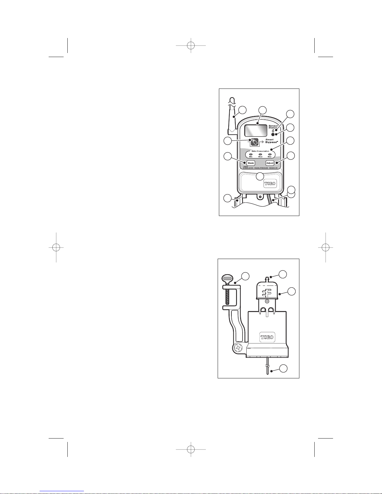
RainSensor Component Overview
Receiver Module
1 -Weather-resistant Cover - Provides protection
from rain and dust. (Keep closed when not
using the receiver).
2 -Setup Button - Accesses the various setup
and operating features.
3 -Smart Bypass
TM
Button - Pressed to bypass
sensor control after it has been activated.
4 -Antenna - Position antenna straight up for
optimum signal reception.
5 -Liquid Crystal Display (LCD) - Provides visual
reference for setup and operation.
6 -Rain and Freeze Sensor Status Indicators -
Illuminate when the RainSensor is active and
watering is on hold.
7 -Water Conservation LED’s - Indicate the water
conservation level selected.
9 -Adjust Button - Pressed to adjust or select values within the setup and oper-
ating features.
10-Connection Cable - Multi-wire cable for connection to controller.
Sensor Module
1 -Test Spindle - Pressed to manually activate
the RainSensor system.
2 -Rain Threshold Adjustment - Adjustable cap
enables the rainfall threshold to be set for
1/8",1/4",1/2"or 3/4" of accumulated rainfall
before the sensor is activated.
3 -Quick-Clip
TM
Mounting Bracket - Simplifies
installation of the sensor module to a rain
gutter, edge of roof, fence post, etc.
4 -Antenna Wire - Position antenna straight down
for optimum signal transmission.
2
2
4
5
6
7
8
9
3
1
2
4
10
3
1
Figure 1
Figure 2
Doc 5 12/21/04 6:36 PM Page 2
Page 3
CAUTION: The receiver requires 24 VAC for operation. Connecting the
receiver to a 120/240 VAC power source will result in severe damage.
The sensor module must not be installed inside a rain gutter or any water
collection vessel. Allowing the sensor to become submerged will result in
severe damage.
Important: Installation of this equipment must comply with all applicable
national and local building and electrical codes. Consult local codes prior to
installation.
Install and Connect the Receiver
1. Install the receiver module next to the controller using the stainless steel
screws or double-sided foam tape provided. Position the antenna straight up.
2. Make sure power to the controller has been disconnected.
3. Route the connection cable into the controller cabinet.
Note: The Wireless RainSensor can operate with either normally-open or
normally-closed sensor circuits. Refer to the controller specifications for
the sensor type required. If the controller is not equipped for direct sensor
connection, skip step 4 and continue at step 5.
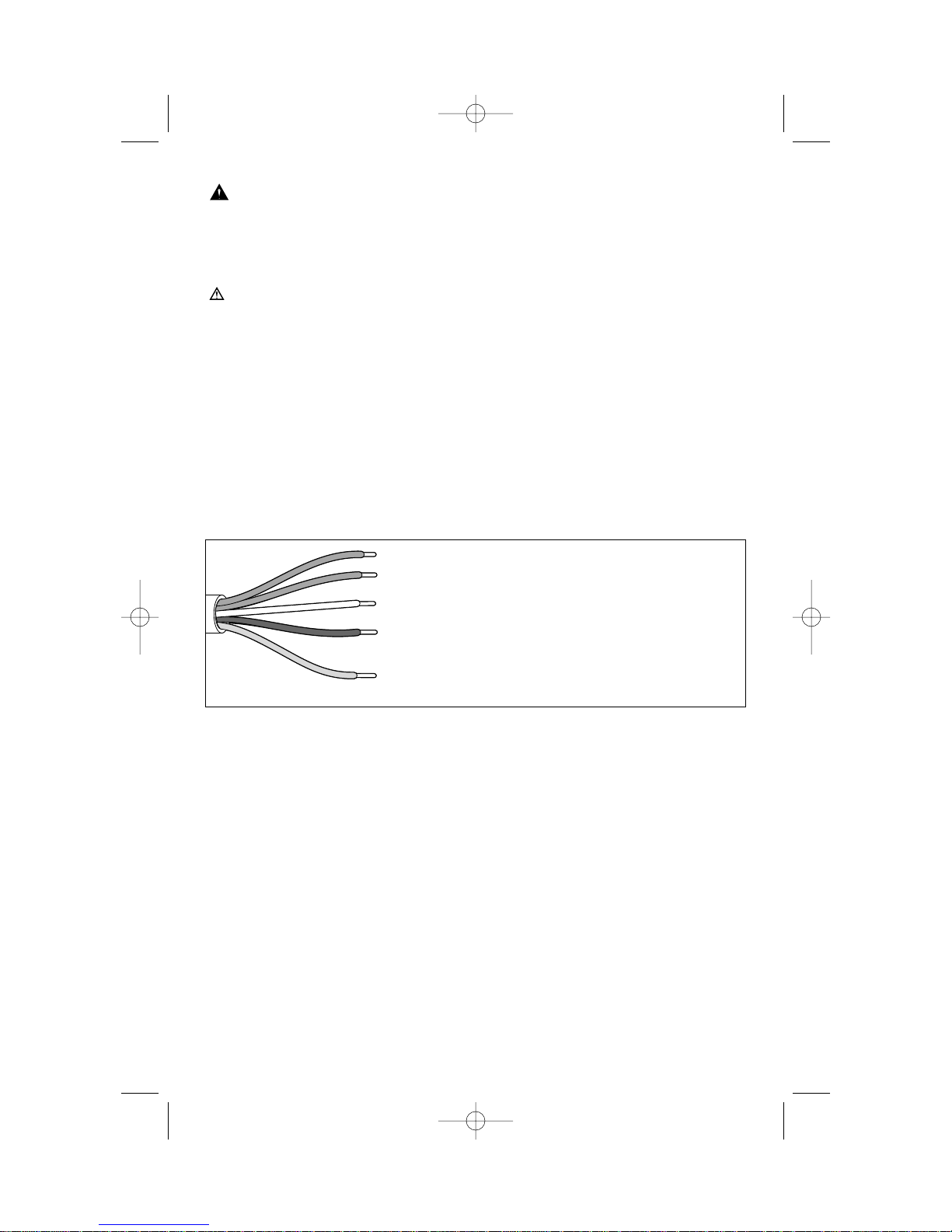
4. Locate the controller’s sensor connection terminals (generally labeled
“SENSOR” or “SEN”) and connect the receiver wires as follows:
For normally-open circuit: Attach the WHITE and BROWN wires.
For normally-closed circuit: Attach the WHITE and YELLOW wires.
Note: Disregard plus (+ ) and minus ( –) polarity labels on the sensor terminals
(if present). Cut or tape back the unused wire.
5. Remove the valve common wire(s) from the terminal labeled “COM”, “C” or “VC.”
6. Attach the BROWN receiver wire to this terminal.
7. Twist the WHITE receiver wire to the valve common wire(s) and secure with the
provided wire nut.
7. Cut or tape back the YELLOW wire.7. Connect the Red power wires to the
controller’s 24 VAC power source terminals.
Note: The receiver requires a constant source of 24 VAC. The controller may
have two terminals dedicated to 24 VAC input, or a 24 VAC Hot Post and
common terminal. Either connection is acceptable. The receiver will not
function properly if connected to a 24 VAC source that is switched on and
off, such as a master valve or pump start circuit.
3
Red – 24 VAC
Red – 24 VAC
White – Sensor Terminal or Valve Common Wire(s)
Brown – Sensor Terminal (Normally-closed)
or Valve Common Terminal
Yellow – Sensor Terminal (Normally-open)
or Valve Common Terminal
Figure 3
Doc 5 12/21/04 6:36 PM Page 3
Page 4
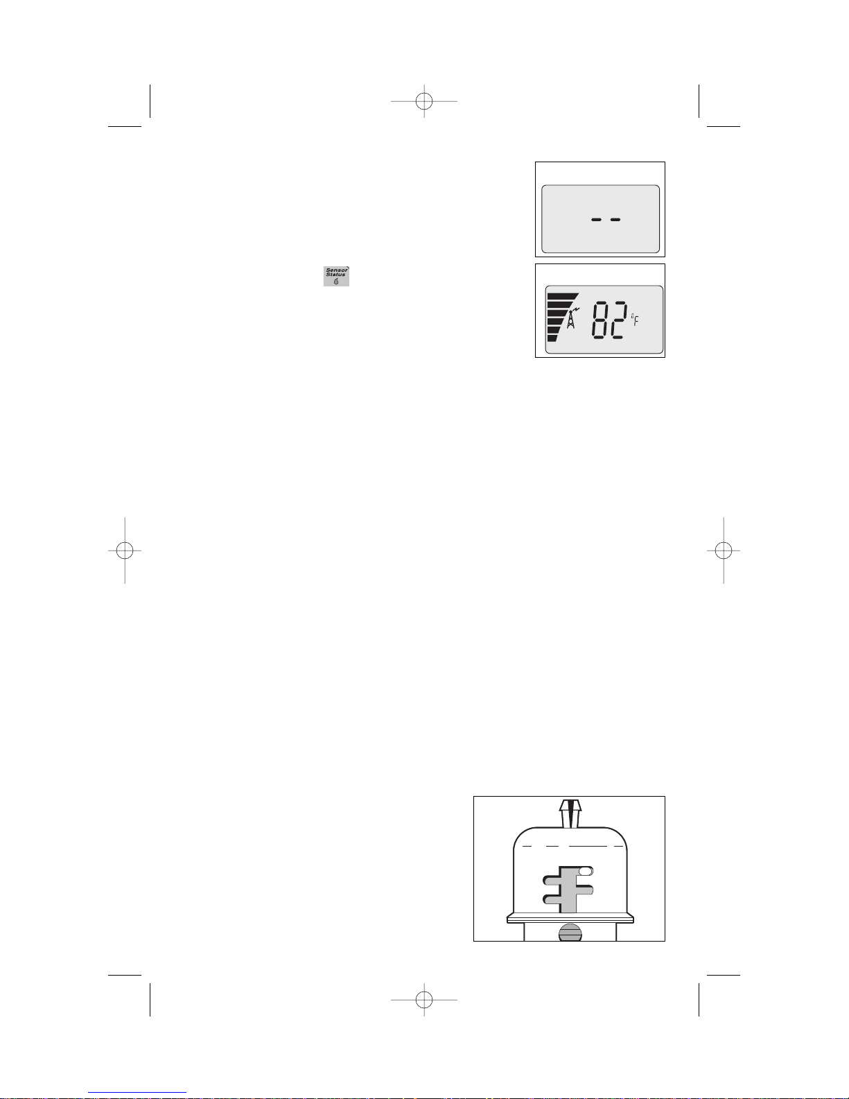
Initial Receiver Testing
1. Apply power to the controller. The receiver will display
two dashes (flashing) indicating that power is present.
2. While holding the sensor module at close range to the
receiver, lightly press and hold down the sensor test
spindle. The receiver will display the following:
• The Sensor Status LED will turn on.
The signal indicator and strength strength bar scale will
be indicated
The current outside air temperature (°F) –
(TWRFS models only).
3. Select an installation site for the sensor module as close to the receiver as
possible to avoid interference of the wireless signal (within 500' line of sight).
Note: The sensor module must be installed where it has unobstructed exposure to rainfall and the sunlight conditions are similar to those of the landscape
being watered. Make sure the sensor module will not be in contact with spray
from the sprinklers or runoff from the roof.
4. Before installing the sensor module, test the signal strength again from the
selected installation site as follows:
To test the Wireless RainSensor operation with the irrigation system controller,
activate a watering zone which is visible from the sensor module location.
Note: The manual activation cycle of some controllers bypasses the sensor
inputs. If the Receiver is connected to the controller’s sensor inputs, you will
need to run an automatic/timed watering program for these types of
controllers.
With the sprinklers on, manually activate the sensor module by pressing and
holding the test spindle. The sprinklers should shut off within a short time. If
they do not shut off, recheck the receiver wiring connections at the controller.
If the controller has a sensor control or bypass switch, make sure the switch is
set to the position that will enable the sensor circuit to be active
5. Prior to installing the sensor module check the current setting on the Rainfall
Adjustment Cap. The sensor module can be adjusted to detect average rainfall
amounts of 1/8", 1/4", 1/2"or 3/4" before signaling the receiver.
To adjust, turn the cap from the current setting and engage the stationary pins
with the desired slot position. Be sure to align the slot and pin properly as this
adjustment does not require excessive force.
The cap indicates measurements in inches on
one side of the cap and millimeters on the
opposite side.
Note: Avoid using the 1/8" setting in highhumidity conditions.
4
Figure 4
Figure 5
Figure 6
Doc 5 12/21/04 6:36 PM Page 4
1/4
3/4
1/8
1/2
Page 5

Installing the Sensor Module
1. The sensor module should be mounted vertically with the antenna wire
extending straight down. Avoid installations where the antenna wire would
contact any metal object.
A rain gutter is an ideal location for the sensor module. Simply position the
bracket with the thumbscrew under the gutter lip and tighten to secure (do not
over-tighten) See Figure 7A.
The sensor module can also be mounted on any suitable solid structure such
as the side of the roof, a shed or fence using the two supplied stainless steel
screws. See Figure 7B.
2. Once securely fastened, adjust the sensor module on the mounting bracket as
needed to align the sensor module housing vertically.
5
Rain gutter (cross section view)
Do not over-tighten
thumbscrew
Press and hold
down to test
Figure 7A
Extended Antenna
straight down
Extended Antenna
straight down
Stainless
Steel
Screws
Figure 7 B
Doc 5 12/21/04 6:36 PM Page 5
Page 6

Receiver Setup
Select Water Conservation Mode
This feature extends the delay period from the time the sensor mechanically
resets until automatic irrigation resumes. Note the matrix provided in the receiver
cover. Select the type of soil and the installed location of the sensor module to
find the initial conservation setting: Minimum (1), Medium (2) or Maximum (3).
1. Press the Setup button. The display will indicate the
current water conservation setting. “Set” will be flashing
and “Water Save” will be displayed See Figure
2. Press the Adjust button to select 1, 2 or 3.
Set Water Delay
This feature provides a rain delay function when rain delay
operation is not included in the controller’s feature set.
Watering can be postponed from 1 to 5 days. The sensor
module will override rain delay.
1. Press the Setup button two times. The display will indicate the current number of rain delay days set. “Set”
will be flashing and “Water Delay” will be displayed.
2. Press the Adjust button to select 0.0 to 5.0.
Set Temperature Threshold (TWRFS models only)
This feature enables the temperature threshold to be set
from 35°F to 45°F or 2°C to 7°C. When the selected
temperature is observed, the sensor will signal to stop
irrigation.
1. Press the Setup button three times. The display will
indicate the current temperature threshold setting.
2. Press the Adjust button to select the temperature.
Set Temperature Scale (TWRFS models only)
This setting enables the temperature scale to be set in
Fahrenheit or Celsius.
1. Press the Setup button four times. The display will indi-
cate the current temperature scale
2. Press the Adjust button to select the alternate scale
Set Dry Out Days
This setting is similar to Water Conservation but enables
the dry out rate to be set in half days The possible settings
are: 0.5, 1.0, 1.5, 2.0. 2.5, 3.0, 3.5 and 4.0 days.
1. Press the Setup button five times. The display will indi-
cate the current Dry out day setting.temperature scale
2. Press the Adjust button to select the desired day
amount.
6
Figure 8
Figure 9
Figure 10
Figure 11
Figure 12
Doc 5 12/21/04 6:36 PM Page 6
Page 7

Signal Strength
This feature enable sensor signal strength to be measured
on a digital scale ranging from 0.0 to 10.2 maximum.
1. Press the Setup button 6 times. The display will indicate
the strength of the last received signal.
Battery Strength
This feature enable sensor battery strength to be measured on the bar scale.
1. Press the Setup button 7 times. The battery symbol and
bar scale will be displayed. The strength of the battery
is determined by the height of the bar stack from no bar
(dead battery) to six bars (full charge).
Wireless Rain/Freeze Sensor Operation
When the sensor module is activated due to a rainfall (or
temperature) threshold being met, the Sensor Status indicator will remain illuminated on the Receiver and the sprinkler system will remain inactive until the moisture-absorbent discs inside the sensor module have dried out. The rate at which
the discs dry out will vary dependent on ambient conditions such as temperature,
sun exposure, humidity and wind—the same conditions your soil experiences.
This allows the Wireless RainSensor to reset when watering is needed again,
enabling the sprinkler system to resume normal operation. The Water
Conservation or Dry Out day setting will hold off resumption of watering for an
extended period as set.
Using the Smart Bypass Feature
Your Wireless RainSensor can be temporarily deactivated by using the built-in
Smart Bypass button. Simply press this button once to bypass current
RainSensor control. The Sensor Status light will blink until the next time the
sensor module dries out and automatically resets. Pressing the Smart Bypass
button again resumes the RainSensor control. Pressing the Smart Bypass button
while the RainSensor control is not active (dry) will cause the Receiver to ignore
the next sensor module signal.
Power Down
To turn the Receiver OFF entirely, press and hold the Smart Bypass button until
the Sensor Status Indicator begins blinking rapidly (5–7 seconds). Release the
Smart Bypass button and confirm the Power Indicator goes out and flashes periodically. Simply press the Smart Bypass button once to turn the Receiver back
on.
Receiver Learn Mode
If it becomes necessary to set the Receiver’s address code to that of a new
sensor module, press and hold the Smart Bypass button until the Status and
Signal indicators blink in unison (10+ seconds). Activate the corresponding
sensor module at close range (by pressing down on the Test Spindle) to change
the existing Receiver code to that of the new sensor module. The indicators will
stop blinking upon learning the new code. Pressing the Smart Bypass button
again will exit the learn mode if no valid code is received.
7
Figure 8
Figure 8
Doc 5 12/21/04 6:36 PM Page 7
Page 8

Sensor Module Battery Replacement
1.Carefully unscrew the bottom of the
housing. Slide the circuit board out.
See Figure 9.
2.Remove the battery cover and batteries.
Replace using two 3V CR2032 (or equivalent) batteries. Install with positive (+) side
of the batteries facing up.
Note: Properly dispose of used batteries
per the battery manufacturer’s recommendations.
3.Reassemble the unit in reverse order.
8
CR2032
Batteries
Figure 9
Doc 5 12/21/04 6:36 PM Page 8
Page 9

Solving Reception Problems
The Wireless RainSensor operates under Part 15 of the FCC rules. This means that
it has to comply with certain standards and is only allowed to transmit up to a
certain power level. In rating transmitters of any form, typically a line-of-site value is
used in order to show the relative effectiveness of a transmitter and allow a transmitter and receiver to be compared to one another using a fair method. The Wireless
RainSensor operates up to 300' line-of-site. This means that in an open field, with
no obstructions, the sensor module and Receiver pair will successfully communicate
up to 300' apart. However, in almost all installations, there are obstacles between
the sensor module and Receiver such as walls, floors, etc.
The obstacles will all affect the transmitted signal and typically reduce the radiated
power that will be read by the Receiver. Different objects such as walls and floors
affect the transmitted signal differently depending on the material composition,
geometry and thickness. Typically, most residential and light commercial construction materials do not reduce the effective transmitted signal enough to pose problems under normal installation conditions. However, there are some installations
with very thick, dense walls, or that involve large amounts of radio frequency interference (electrical switching rooms etc.) where the effective range of the Wireless
RainSensor may be greatly reduced.
Some helpful tips on mounting the sensor module and Receiver for the best Radio
Frequency (RF) performance:
•Always try to keep the antennas straight and fully extended (straight up on the
Receiver and straight down on the sensor module).
•Try to maintain a parallel orientation of one antenna to the other. Avoid installing
either unit where the antennas are in close proximity to large metal objects.
•Attempt to mount the units as close together as possible to reduce the potential
for interference or signal reduction. If the signal strength is not good in one location, try another location - even as little as a few feet of movement can change
from a weak spot to a strong spot. Interior locations where cell phones or cordless phones have trouble with reception may indicate areas with poor RF signal
transmission.
•If possible avoid an installation where the sensor module is located exactly above
the Receiver. Move the sensor module slightly offset to one side. When the RF
signal is passing through walls, keep in mind that it has less thickness to penetrate when it passes straight through the wall. In other words, passing diagonally
through a wall increases its effective thickness.
9
Doc 5 12/21/04 6:36 PM Page 9
Page 10

Electromagnetic Compatibility
Domestic: This device complies with FCC rules Part 15. Operation is subject to
the following two conditions: (1) This device may not cause harmful interference
and (2) this device must accept any interference that may be received, including
interference that may cause undesirable operation.
This equipment generates and uses radio frequency energy and if not installed
and used properly, that is, in strict accordance with the manufacturer's instructions, may cause interference to radio and television reception. It has been type
tested and found to comply with the limits for a FCC Class B computing device in
accordance with the specifications in Subpart J of Part 15 of FCC Rules, which
are designed to provide reasonable protection against such interference in a residential installation. However, there is no guarantee that interference will not occur
in a particular installation. If this equipment does cause interference to radio or
television reception, which can be determined by turning the equipment off and
on, the user is encouraged to try to correct the interference by one or more of the
following measures:
Reorient the receiving antenna, relocate the remote control receiver with respect
to the radio/TV antenna or plug the irrigation controller into a different outlet so
that the irrigation controller and radio/TV are on different branch circuits.
If necessary, the user should consult the dealer or an experienced radio/television
technician for additional suggestions. The user may find the following booklet
prepared by the Federal Communications Commission helpful:
"How to Identify and Resolve Radio-TV Interference Problems". This booklet is
available from the U.S. Government Printing Office, Washington, DC 20402.
Stock No. 004-000-00345-4.
10
Doc 5 12/21/04 6:36 PM Page 10
Page 11

Specifications:
Receiver Mounting Options: Stainless steel screws and/or double-sided foam
tape.
Sensor module Mounting Options: Quick-Clip
TM
rain gutter bracket and roof
eaves/fascia mounting bracket with stainless steel screws.
Sensor module Range: Up to 300' line-of-site.
Sensor Type: Industry-standard hygroscopic disc stack with adjustable rainfall
sensitivity.
Transmitter Battery Type: (2) 3V cells - CR2032 (or equivalent).
Average Battery Life: Five years
Operating Temperature Range: -20°F to 120°F
Receiver Power Input: 22–28 VACc/VDC, 100mA (from existing controller/timer
with Class 2, UL-approved transformer).
Relay Contacts Output: Normally Open (NO) and Normally Closed (NC)
3A at 24 VAC.
Receiver Controls: Sensor Status Indicator, Signal Indicator, Smart Bypass
Switch, Power Indicator with low battery/poor communication warning.N
11
Doc 5 12/21/04 6:36 PM Page 11
Page 12

The Toro Promise — Limited Five-Year Warranty
The Toro Company and its affiliate, Toro Warranty Company, pursuant to
an agreement between them, jointly warrants, to the owner, each new piece
of equipment (featured in the current catalog at date of installation) against
defects in material and workmanship for for a period described below,
provided they are used for irrigation purposes under manufacturer's recommended specifications. Product failures due to acts of God (i.e., lightning,
flooding, etc.) are not covered by this warranty.
Neither Toro nor Toro Warranty Company is liable for failure of products not
manufactured by them even though such products may be sold or used in
conjunction with Toro products.
During such warranty period, we will repair or replace, at our option, any part
found to be defective. Your remedy is limited solely to the replacement or repair
of defective parts.
Return the defective part to your local Toro distributor, who may be listed in
your telephone directory Yellow Pages under "Irrigation Supplies" or "Sprinkler
Systems," or contact The Toro Warranty Company P.O. Box 489, Riverside,
California, 92502. Phone (800) 664-4740 for the location of your nearest Toro
distributor or outside the U.S., call (951) 688-9221.
This warranty does not apply where equipment is used, or installation is
performed in any manner contrary to Toro’s specifications and instructions, nor
where equipment is altered or modified.
Neither Toro nor Toro Warranty Company is liable for indirect, incidental or
consequential damages in connection with the use of equipment, including but
not limited to: vegetation loss, the cost of substitute equipment or services
required during periods of malfunction or resulting non-use, property damage
or personal injury resulting from installer’s actions, whether negligent or otherwise.
Some states do not allow the exclusion or limitation of incidental or consequential damages, so the above limitation or exclusion may not apply to you.
All implied warranties, including those of merchantability and fitness for use,
are limited to the duration of this express warranty.
Some states do not allow limitations of how long an implied warranty lasts,
so the above limitation may not apply to you.
This warranty gives you specific legal rights and you may have other rights
which vary from state to state.
The Toro Wireless Rain Sensor models TWRS and TWRFS are covered by
this warranty for a period of five years from the date of installation.
12
© 2004 The Toro Company,
P.O. Box 489, Riverside CA, 92502
Toro HelpLine - 800-664-4740 www.toro.com Form Number 373-0332 Rev 1
Doc 5 12/21/04 6:36 PM Page 12
 Loading...