

Page 1

FormNo.3425-850RevC
VersaVac
ModelNo.07053—SerialNo.403360001andUp
Registeratwww.T oro.com.
OriginalInstructions(EN)
*3425-850*C
Page 2

ThisproductcomplieswithallrelevantEuropean
directives.Fordetails,pleaseseetheseparate
productspecicDeclarationofConformity(DOC)
sheet.
WARNING
CALIFORNIA
Proposition65Warning
Useofthisproductmaycauseexposure
tochemicalsknowntotheStateof
Californiatocausecancer,birthdefects,
orotherreproductiveharm.
Introduction
TheVersaVacistobeusedinconjunctionwiththe
combinationdeckorngerdeck.Themachineis
intendedtobeusedbyprofessional,hiredoperators
incommercialapplications.Themachineisdesigned
todethatch,renovate,andremovedebrisfromlarge
turfareasin1pass.
Readthisinformationcarefullytolearnhowtooperate
andmaintainyourproductproperlyandtoavoid
injuryandproductdamage.Youareresponsiblefor
operatingtheproductproperlyandsafely .
Visitwww.Toro.comforproductsafetyandoperation
trainingmaterials,accessoryinformation,helpnding
adealer,ortoregisteryourproduct.
Wheneveryouneedservice,genuineToroparts,or
additionalinformation,contactanAuthorizedService
DealerorToroCustomerServiceandhavethemodel
andserialnumbersofyourproductready.Figure1
identiesthelocationofthemodelandserialnumbers
ontheproduct.Writethenumbersinthespace
provided.
ModelNo.
SerialNo.
Thismanualidentiespotentialhazardsandhas
safetymessagesidentiedbythesafety-alertsymbol
(Figure1),whichsignalsahazardthatmaycause
seriousinjuryordeathifyoudonotfollowthe
recommendedprecautions.
g000502
Figure1
Safety-alertsymbol
Thismanualuses2wordstohighlightinformation.
Importantcallsattentiontospecialmechanical
informationandNoteemphasizesgeneralinformation
worthyofspecialattention.
Contents
Safety.......................................................................3
GeneralSafety...................................................3
SafetyandInstructionalDecals..........................3
Setup........................................................................6
1ConnectingtheMachinetotheTraction
Unit.................................................................7
2AdjustingthePTOShaftLength.......................7
3ConnectingthePTOShaft...............................7
4GreasingtheMachine......................................8
ProductOverview.....................................................8
Controls.............................................................8
BeforeOperation...................................................9
BeforeOperationSafety.....................................9
HydraulicFluidSpecications...........................10
CheckingtheHydraulicFluid.............................11
CheckingtheTirePressure................................11
CheckingtheT orqueoftheWheel
Nuts...............................................................11
ConnectingtheMachinetotheTraction
Unit................................................................11
ConnectingthePTOShaft................................12
DuringOperation.................................................13
DuringOperationSafety...................................13
OperatingtheTractionUnitHydraulics..............14
OperatingtheMachine.....................................14
AfterOperation....................................................15
AfterOperationSafety......................................15
RemovingtheMachinefromtheTraction
Unit...............................................................15
TransportingtheMachine.................................15
Maintenance...........................................................16
RecommendedMaintenanceSchedule(s)...........16
MaintenanceSafety..........................................16
LubricatingtheMachine....................................17
HydraulicSystemSafety...................................17
CheckingtheHydraulicLinesand
Hoses............................................................18
ServicingtheHydraulicFluidandFilter.............18
Storage...................................................................20
©2018—TheToro®Company
8111LyndaleAvenueSouth
Bloomington,MN55420
Contactusatwww.Toro.com.
2
PrintedintheUSA
AllRightsReserved
Page 3
Safety
GeneralSafety
Thisproductiscapableofamputatinghandsand
feetandofthrowingobjects.Alwaysfollowallsafety
instructionstoavoidseriouspersonalinjury.
Usingthisproductforpurposesotherthanitsintended
usecouldprovedangeroustoyouandbystanders.
•Readandunderstandthecontentsofthis
Operator’sManualbeforeusingthemachine.
•Donotputyourhandsorfeetnearmoving
componentsofthemachine.
•Useyourfullattentionwhileoperatingthe
machine.Donotengageinanyactivitythat
causesdistractions;otherwise,injuryorproperty
damagemayoccur.
•Donotoperatethemachinewithoutallguards
andothersafetyprotectivedevicesinplaceand
functioningproperlyonthemachine.
•Keepclearofanydischargeopening.Keep
bystandersandpetsasafedistanceawayfrom
themachine.
•Keepchildren,bystanders,andpetsoutofthe
operatingarea.Neverallowchildrentooperate
themachine.
•Alwaysshutofftheengineofthetractionunit,
removethekey(ifequipped),waitforallmoving
partstostop,andallowthemachinetocool
beforeadjusting,servicing,cleaning,orstoring
themachine.
Improperlyusingormaintainingthismachinecan
resultininjury .T oreducethepotentialforinjury,
complywiththesesafetyinstructionsandalways
payattentiontothesafety-alertsymbol
meansCaution,Warning,orDanger—personalsafety
instruction.Failuretocomplywiththeseinstructions
mayresultinpersonalinjuryordeath.
Youcanndadditionalsafetyinformationwhere
neededthroughoutthismanual.
,which
SafetyandInstructionalDecals
Safetydecalsandinstructionsareeasilyvisibletotheoperatorandarelocatednearanyarea
ofpotentialdanger.Replaceanydecalthatisdamagedormissing.
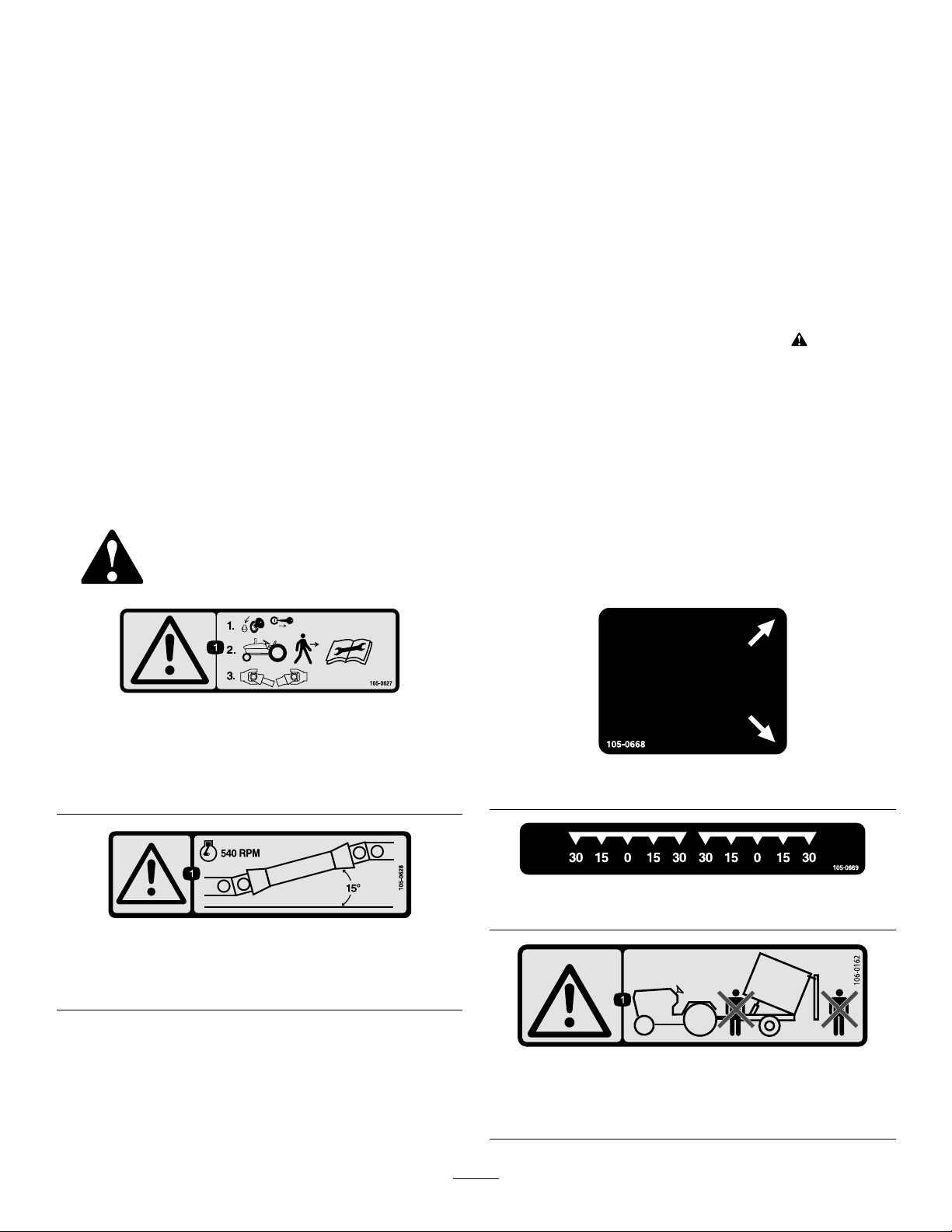
105-0627
1.Warning—stoptheengineandremovetheignitionkey
beforegettingoffofthetractor;readtheinstructionsbefore
servicingorperformingmaintenance,thendisconnectthe
PTOshaft.
105-0628
decal105-0627
decal105-0668
105-0668
decal105-0669
105-0669
decal105-0628
1.Warning—runtheengineatnomorethan540rpmand
keepthePTOshaftangleunder15degrees.
decal106-0162
106-0162
1.Warning—donotstandinfrontoforbehindthetrailerwhen
dumping.
3
Page 4
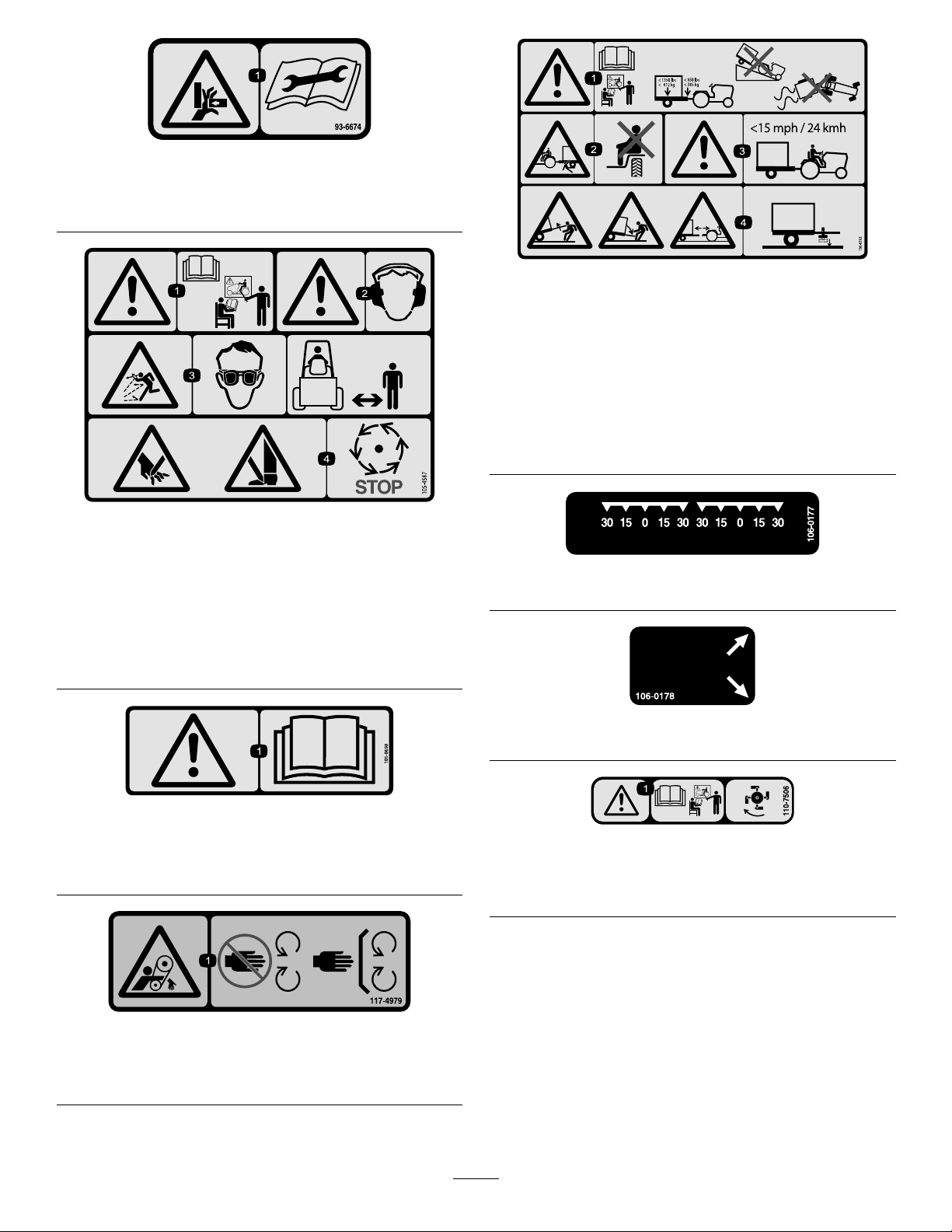
93-6674
1.Crushinghazard,hand—readtheinstructionsbefore
servicingorperformingmaintenance.
105-4587
decal93-6674
decal106-0163
106-0163
1.Warning—readtheOperator'sManualandreceivetraining
beforeoperatingthemachine;themaximumloadis612kg
(1350lb)trailerweightand385kg(850lb)tongueweight;
donotdrivethemachineandtrailerdownhilloryoumay
losecontrol.
2.Crushinghazard,trailer—donotcarrypassengers.
3.Warning—donotexceed24km/h(15mph).
4.Storedenergyhazard,trailer—donotdisconnectthetrailer
withoutrstputtingdownthejack.
decal105-4587
1.Warning—readthe
Operator'sManualand
receivetrainingbefore
operatingthemachine.
3.Thrownobject
hazard—weareye
protection;keep
bystandersasafedistance
fromthemachine.
2.Warning—wearhearing
protection.
4.Cuttinghazardofhand
orfoot—waitformoving
partstostop.
105-0698
Applyoverdecal105-0707forCEcompliance
1.Warning—readtheOperator’sManual.
decal106-0177
106-0177
decal106-0178
106-0178
decal105-0698
decal110-7506
110-7506
1.Warning—readtheOperator’sManualandreceivetraining;
beforeoperatingthecombinationdeckail.
117-4979
1.Entanglementhazard,belt—keepawayfrommovingparts;
keepallguardsandshieldsinplace.
decal117-4979
4
Page 5
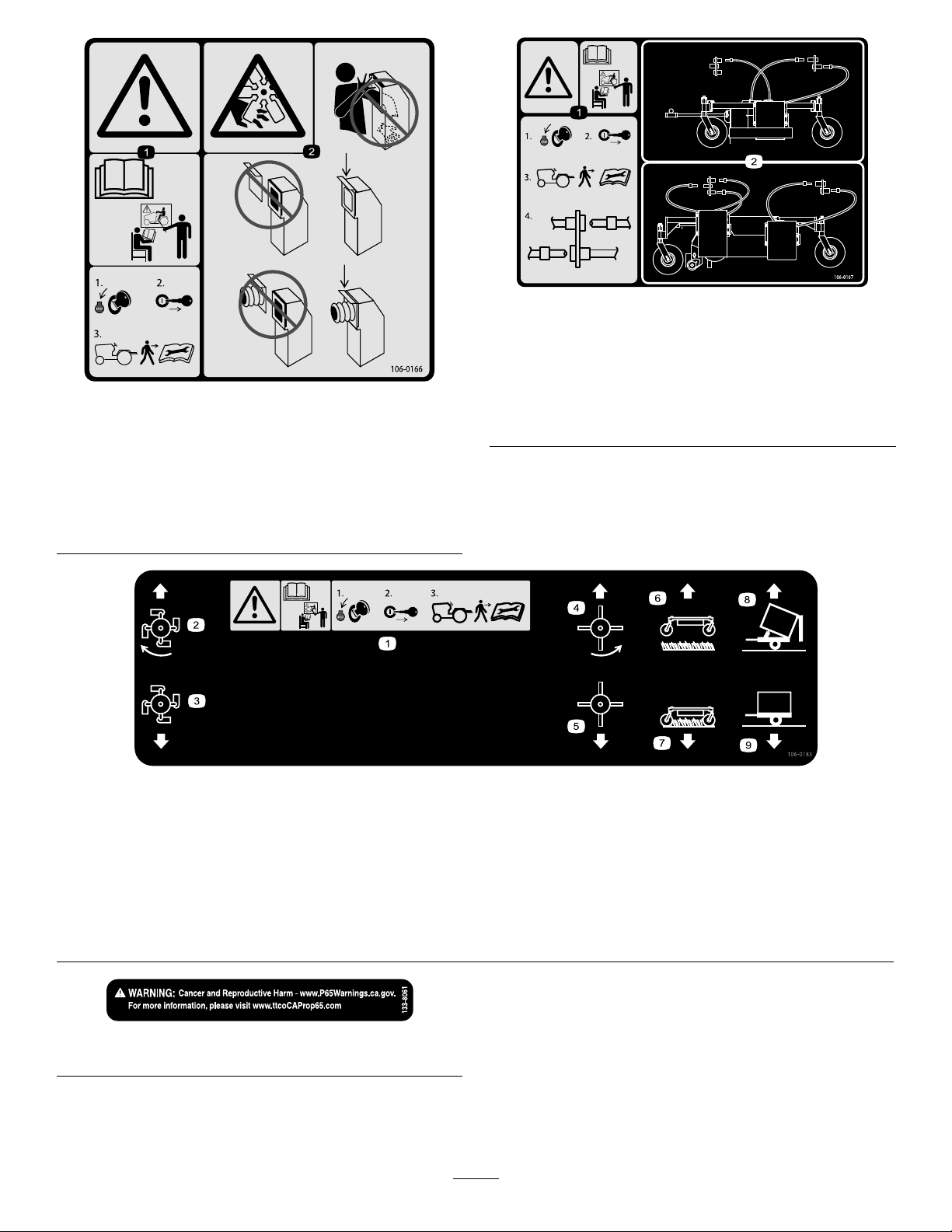
106-0166
1.Warning—readtheandreceivetrainingbeforeoperating
themachine;stoptheengineandremovetheignitionkey
beforegettingoffofthetractor;readtheOperator'sManual
beforeservicingorperformingmaintenance.
2.Cutting/dismembermenthazardofhand,fan—donotplace
yourhandorarminthevacuumchute;keepthehosedoor
orhoseinstalledatalltimes.
decal106-0167
106-0167
1.Warning—readtheandreceivetrainingbeforeoperating
themachine;1)Stoptheengine;2)Removetheignition
keybeforegettingoffofthetractor;3)readtheOperator's
decal106-0166
Manualbeforeservicingorperformingmaintenance;4)
Connectordisconnectthehydraulichoses.
2.Hydraulichoseroutingandconnections.
1.Warning—readtheandreceivetraining
beforeoperatingthemachine;1)Stop
theengineandremovetheignitionkey
beforegettingoffofthetractor;2)Read
theOperator'sManualbeforeservicing
orperformingmaintenance.
2.Flailon
3.Flailoff
133-8061
106-0183
4.Rubberngerson
5.Rubberngersoff
6.Vacuumunitup9.Trailerupright
decal133-8061
7.Vacuumunitdown
8.Trailerdump
5
decal106-0183
Page 6

Setup
LooseParts
Usethechartbelowtoverifythatallpartshavebeenshipped.
ProcedureDescription
1
2
3
4
Jack1
PTOshaft
Nopartsrequired
Nopartsrequired
MediaandAdditionalParts
Description
Auxiliarycontrollever1
Operator’sManual
DeclarationofConformity
Qty.
Qty.
Connectthemachinetothetraction
units.
1
–
–
Installthecontrolleveronlyifthecombinationdeckis
installed.
1
1
Readbeforeoperatingthemachine.
UseforCEcompliance.
AdjustthePTOshaftlength.
ConnectthePTOshaft.
Greasethemachine.
Use
Use
6
Page 7

CAUTION
Withouttheproperamountofballastinthe
tires,thetractionunitmaybecomeunstable
andcausebodilyinjury.
Makesurethatthefrontofthetractionunitis
equippedwiththeproperamountofballast;
refertothetractionunitOperator’sManualfor
ballastrequirements.
1
ConnectingtheMachineto theTractionUnit
Partsneededforthisprocedure:
1Jack
Procedure
RefertoConnectingtheMachinetotheTractionUnit
(page1 1).
2
AdjustingthePTOShaft Length
Partsneededforthisprocedure:
1
PTOshaft
Procedure
AlongPTOshaftissuppliedwiththemachineto
accommodatetractionunitswithlargerPTOshaft
variations.Formosttractionunits,thisshaftistoo
longandmustbecuttothecorrectlengthordamage
mayresult.
1.Measurethedistancefromthelockgrooveof
thetractionunitPTOshafttothelockgrooveof
themachineimpellerinputshaft.
Note:Recordthisdimension.
2.FullycollapsethePTOshaftandmeasurethe
distancebetweenthelockpincollars.
3.Atitsshortestlength,the2halvesofthePTO
shaftmusthaveatleast37mm(1-1/2inches)of
additionalclearancetocollapse(Figure2).
Note:IfthedimensioninStep1isnotatleast
37mm(1-1/2inches)greaterthanthedimension
inStep2,thePTOshaftistoolong;proceedto
step4.Ifthereisenoughclearancetoallowthe
PTOshafttocollapse,proceedtoStep9.
g027354
Figure2
1.PTOshaft
4.Usethefollowingcalculationtoestablish
howmuchshortertheshaftmustbe,when
connected,toensureaclearanceof37(1-1/2
inches):
A.SubtractthedimensionrecordedinStep2
fromthedimensionrecordedinStep1.
Note:Recordthisdimension.
B.SubtracttheresultinStepAfrom37mm
(1-1/2inches).
Note:ThePTOshaftmustbeshortened
bythisamount.
5.Usingahacksaw,shortentheguardsandthe
steeltubesbythecalculatedlength.
Note:CutbothhalvesofthePTOshaft.
6.Deburrtheendsofthesteeltubesinternallyand
externally.
7.Removealldebrisfromthetubesections.
8.Greasethesteeltubesliberally .
9.AssemblethePTOshaftandsecureittothe
machineandtractionunit.
10.Measuretheshaft;ifitisnotatleast37mm
(1-1/2inches),repeattheprocedure.
Note:Recordthisdimension.
7
Page 8
ProductOverview
3
ConnectingthePTOShaft
NoPartsRequired
Procedure
ConnectthePTOshaft;refertoConnectingthePTO
Shaft(page12)
4
GreasingtheMachine
NoPartsRequired
Procedure
Greasethemachine;refertoLubricatingtheMachine
(page17)
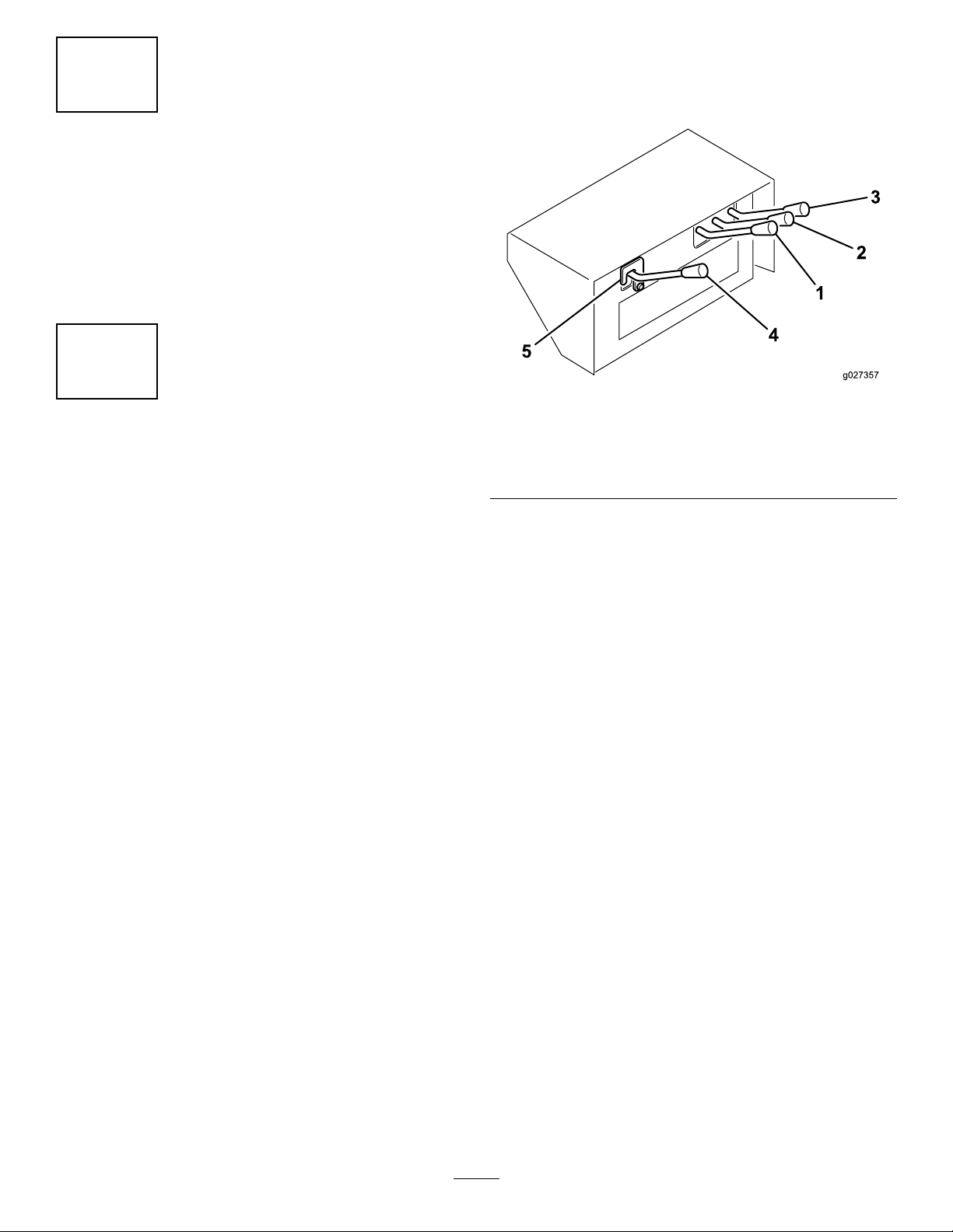
Controls
g027357
Figure3
1.Brushcontrol4.Auxiliarycontrol
2.Deckliftcontrol5.Safetylatch
3.Trailerliftcontrol
TrailerLiftControl
Usedtodumpthetrailerbox(Figure3).Theup
positionraisestheboxandopensthedoor,andthe
downpositionlowerstheboxandclosesthedoor.
DeckLiftControl
Usedtoraiseandlowertheprimarydeck(Figure
3).Theuppositionraisesthedeck,andthedown
positionlowersthedeck.
BrushControl
Usedtooperatetherotatingngerdeck(sold
separately).Theuppositionstartsthedeck,andthe
downpositionstopsthedeck(Figure3).
AuxiliaryControl
Usedtooperatethecombinationdeck(sold
separately).Theuppositionstartsthedeck,andthe
downpositionstopsthedeck(Figure3).
Important:Theauxiliarycontrolleverisshipped
loosetopreventaccidentalengagementofthe
unusedhydrauliccircuit.Donotinstalloroperate
theauxiliarycontrolleverunlessthecombination
deckisinstalled.
Toinstalltheauxiliarycontrollever,completethe
followingprocedure:
1.Removethecontrollevercover.
8
Page 9

2.Removethe2cotterpinsfromthecontrolvalve
spool.
Operation
3.Mounttheauxiliarycontrollevertothevalve
spoolwiththecotterpins.
4.Installthecontrollevercover.
SafetyLatch
Onlyremovethesafetylatchwhenoperatingthe
combinationdeck(Figure3).
TractionUnitPTO
Thevacuumfanonthemachinewillrunassoon
asthePTOisengaged(Figure3).Thengerand
combinationdecksareengagedbythehydraulic
controlsonthemachine.
Important:AlwaysengagethetractionunitPTO
gentlyatalowenginespeed.Suddenengagement
ofthetractionunitPTOatahighenginespeedwill
likelycausedamagetothedrivelinecomponents.
Note:Determinetheleftandrightsidesofthe
machinefromthenormaloperatingposition.
CAUTION
Ifyouleavethekeyinthetractionunitignition
switch,someonecouldaccidentlystartthe
engineandseriouslyinjureyouorother
bystanders.
Removethekeyfromthetractionunitignition
beforeyoudoanymaintenance.
BeforeOperation
BeforeOperationSafety
GeneralSafety
•Donotallowchildrenoruntrainedpeopleto
operateorservicethemachine.Localregulations
mayrestricttheageoftheoperator.Theowner
isresponsiblefortrainingalloperatorsand
mechanics.
•Becomefamiliarwiththesafeoperationofthe
equipment,operatorcontrols,andsafetysigns.
•Knowhowtostopthemachineandshutoffthe
enginequickly.
•Donotoperatethemachinewithoutallguards
andothersafetyprotectivedevicesinplaceand
functioningproperlyonthemachine.
•Ensurethatallhydrauliclineconnectorsaretight,
andallhydraulichosesandlinesareingood
conditionbeforeapplyingpressuretothesystem.
•Beforeoperating,alwaysinspectthemachineto
ensurethattheailknivesareingoodworking
condition.Replacewornordamagedknives.
•Inspecttheareawhereyouwillusethemachine
andremoveallobjectsthatthemachinecould
strike.
•Ensurethatyourtractionunitissuitableforuse
withanimplementofthisweightbycheckingwith
yourtractionunitsupplierormanufacturer.
•Thetractionunitmusthavetheproperwheelbase
andtreadwidthandbeequippedwitharollbar
andseatbelttooperatesafelyonhillyterrain.
Thenormaloperatingspeedis10km/h(6mph)
butwillvarywithterrainanddebrisbeingpicked
up.Themaximumtransportspeedis24km/h(15
mph)withslowerspeedsrequiredonhillyterrain.
RefertothetractionunitOperator’sManualfor
informationortractionunitserviceagencyifyou
haveanyquestionsonsafeoperation.
9
Page 10

•Thebrakesofthetowtractionunitmusthave
thecapacitytostopthemachinewithmachine
fullyloadedandtravelingatthemaximum
recommendedtransportspeed.
•Thepowertake-offdriveofthemachinerequiresa
tractionunitwithoperatingspeedsof540rpmand
outputpowerof32hporhigher.Donotexceed
the540rpmspeed.
•Themachinemustcomplywithlocalroad
requirementsiftransportedonpublicroads.A
slow-movingvehiclesignhasbeenprovided.
Signallightsandbrakesarenotprovidedandmay
berequiredinsomeareas.
HydraulicFluid
Specications
Thereservoirislledatthefactorywithapproximately
38L(10USgallons)ofhigh-qualityhydraulicuid.
Checkthelevelofthehydraulicuidbeforeyourst
starttheengineanddailythereafter;refertoChecking
theHydraulicFluid(page11).
Recommendedreplacementuid:ToroPX
ExtendedLifeHydraulicFluid;availablein19L(5US
gallon)pailsor208L(55USgallon)drums.
Note:Amachineusingtherecommended
replacementuidrequireslessfrequentuidandlter
changes;refertoServicingtheHydraulicFluidand
Filter(page18).
Alternativeuids:IfT oroPXExtendedLife
HydraulicFluidisnotavailable,youmayuseanother
conventional,petroleum-basedhydraulicuidhaving
specicationsthatfallwithinthelistedrangeforallthe
followingmaterialpropertiesandthatitmeetsindustry
standards.Donotusesyntheticuid.Consultwith
yourlubricantdistributortoidentifyasatisfactory
product.
Note:T orodoesnotassumeresponsibilityfor
damagecausedbyimpropersubstitutions,souse
productsonlyfromreputablemanufacturerswhowill
standbehindtheirrecommendation.
HighViscosityIndex/LowPourPoint
Anti-wearHydraulicFluid,ISOVG46
MaterialProperties:
Viscosity,ASTMD445cSt@40°C44to48
ViscosityIndexASTMD2270
PourPoint,ASTMD97-34°Fto-49°F
IndustrySpecications:EatonVickers694(I-286-S,
M-2950-S/35VQ25or
140orhigher
M-2952-S)
Note:Manyhydraulicuidsarealmostcolorless,
makingitdifculttospotleaks.Areddyeadditivefor
thehydraulicuidisavailablein20ml(0.67oz)
bottles.Abottleissufcientfor15to22L(4to6US
gallons)ofhydraulicuid.OrderPartNo.44-2500
fromyourauthorizedTorodistributor.
10
Page 11

CheckingtheHydraulic
CheckingtheTirePressure
Fluid
1.Operatethemachinesothattheuidiswarm,
parkthemachineonalevelsurface,andshut
offtheengine.
2.Checktheleveloftheuidbyviewingthesight
gauge(Figure4).Iftheuidisuptothemiddle
ofthegauge,theuidlevelissufcient.
Figure4
1.Sightgauge
2.Hydraulicreservoircap
Thecorrectairpressureinthetiresis124kpa(18psi).
Important:Maintainevenpressureinbothtires
toensurepropermachineperformance.Donot
underinate.
CheckingtheTorqueofthe WheelNuts
ServiceInterval:Aftertherst2hours
Aftertherst10hours
Every200hours
WARNING
Failuretomaintainthepropertorqueofthe
wheelnutscouldresultinfailureorlossof
thewheelandmayresultinpersonalinjury.
ConnectingtheMachineto theTractionUnit
g027356
1.Positionthemachineonaat,levelsurface.
2.Insertthejackontotheframepinandsecureit
withthepin(Figure5).
3.Iftheuidlevelisbelowthemiddleofthegauge,
removethecapfromthehydraulicuidreservoir
andslowlyaddanappropriatehydraulicuid
untilthelevelreachesthemiddle(maximum)of
thesightgauge;refertoServicingtheHydraulic
FluidandFilter(page18).
Important:Donotoverll;ifyouexceed
themaxlllineofthesightgaugeyoumust
removetheexcessuid;refertoChanging
theHydraulicFluid(page18).
Important:Topreventsystem
contamination,cleanthetopofthe
hydraulicuidcontainersbeforepuncturing.
Ensurethatthepourspoutandthefunnel
areclean.
4.Installthereservoircap.
g027352
Figure5
1.Jack3.Framepin
2.Pin
3.Adjustthejackheightuntilthemachineframeis
parallelwiththeground.
4.Backthetractionunituptothemachine.
11
Page 12

5.Adjustthemachinehitchclevistothesamelevel
asthetractionunithitchasfollows:
A.Removetheboltsandlocknutsthatsecure
thehitchclevis(Figure6)tothemachine
frame.
ConnectingthePTOShaft
1.ConnectthePTOshafttothemachineimpeller
inputshaft.
2.ConnectthePTOshafttothereartractionunit
PTOshaft.
3.SlidethePTOshaftforwardasfarasitwillgo.
4.PressthepintosecurethePTOshaftinplace.
Note:SlidethePTOshaftbackandforthto
ensurethatitisproperlylocked.
5.Connecttheshieldsafetychaintothetraction
unit(Figure7).
Note:Ensurethatthechainremainsslack
whenyouturnthetractionunit.
Figure6
1.Clevishitch
B.Raiseorlowerthehitchclevistotheposition
approximatelylevelwiththetractionunit
hitch.
C.Secureitwiththeboltsandlocknutsthat
werepreviouslyremoved.
6.Connectthetractionunithitchtothemachine
clevishitchwiththehitchpinandclevis.
7.Removethejackpin,rotatethejackupwardto
thestorageposition.
g027353
g027355
Figure7
1.Safetychain
CAUTION
Iftheshieldchainsarenotconnected,
theshieldscouldrotateduringoperation
andcausebodilyinjury.
KeepallPTOshieldsinplaceand
connecttheshieldchaintothetraction
unitorPTOshields.
12
Page 13

DuringOperation
DuringOperationSafety
GeneralSafety
•Theowner/operatorcanpreventandisresponsible
foraccidentsthatmaycausepersonalinjuryor
propertydamage.
•Wearappropriateclothing,includingeye
protection;slip-resistant,substantialfootwear;
longpants;andhearingprotection.Tieback
longhairanddonotwearlooseclothingorloose
jewelry.
•Useyourfullattentionwhileoperatingthe
machine.Donotengageinanyactivitythat
causesdistractions;otherwise,injuryorproperty
damagemayoccur.
•Donotoperatethemachinewhentired,ill,or
undertheinuenceofalcoholordrugs.
•Donotcarrypassengersonthemachineand
keepbystandersandpetsawayfromthemachine
duringoperation..
•Thebrush,rubberngers,ail,andvacuumof
themachinemaypickupandpropeldebrisand
smallobjectsinitspathduringoperation;keep
bystandersandpetsawayfromthemachine
duringoperation.
•AlwaysdisengagethePTO,shutofftheengineof
thetractionunit,removethekey,andwaitforall
movingpartstostopbeforeleavingtheoperator’s
position.
•DonotstepoverthePTOshafttogettotheother
sideofthemachine.Walkaroundthemachine.
•Alwaysstandawayfromtherearofthemachine
whenopeningthereardoor.
•Operatethemachineonlyingoodvisibilitytoavoid
holesorhiddenhazards.
•Keepyourhandsandfeetawayfromtheail
knives.
•Lookbehindanddownbeforebackinguptobe
sureofaclearpath.
•Stopthemachine,shutofftheengine,waitforall
movingpartstostop,andinspectthemachine
afterstrikinganobjectorifthereisanabnormal
vibrationinthemachine.Makeallnecessary
repairsbeforeresumingoperation.
•Alwaysmaintainpropertractionunittirepressure.
•Ensurethatyoucomplywithallregulationsbefore
transportingequipmentonthepublicroadsand
highways.Makesurethatallrequiredreectors
andlightsareinplaceandarecleanandvisibleby
overtakingandoncomingtrafc.
•Reducespeedonroughroadsandsurfaces
•ForallPTOshaftsteelparts(tubes,bearings,
joints,etc.)disassemblyorrepairs,itishighly
advisabletocontactyourauthorizedT oro
distributor.Removalofcomponentsforrepairs
andreassemblymaydamagesomepartsifnot
performedwithspecialtoolsbytrainedtechnicians.
•ThePTOshaftmustnotbeusedwithoutthe
guardssupplied.
DumpingSafety
•Movingthereardooranddumpingdebriscan
causeseriousinjury.Stayclearofthemachine
whileitisbackingupordumping.
•Keepbystandersasafedistancefromthemachine
whenoperatingtodumpdebrisorwhenopening
andclosingthereardoor.
•Underrarecircumstanceswet,compressedgrass
clippingsmaygenerateheat.Alwaysemptythe
machinebeforestoringit.
•Toavoidtheriskofelectricalshock,dumpthe
machineonlyinareasthatareclearofoverhead
wiresandotherobstructions.
•Neverdumpthemachineonaslope;always
dumpthemachineonlevelground.
SlopeSafety
•Reviewthetractionunitspecicationstoensure
thatyoudonotexceeditsslopecapabilities.
•Slopesareamajorfactorrelatedtolossofcontrol
androlloveraccidents,whichcanresultinsevere
injuryordeath.Y ouareresponsibleforsafeslope
operation.Operatingthemachineonanyslope
requiresextracaution.
•Evaluatethesiteconditionstodetermineifthe
slopeissafeformachineoperationincluding
surveyingthesite.Alwaysusecommonsense
andgoodjudgmentwhenperformingthissurvey .
•Reviewtheslopeinstructionslistedbelowfor
operatingthemachineonslopesandreviewthe
conditionstodeterminewhetheryoucanoperate
themachineintheconditionsonthatdayandat
thatsite.Changesintheterraincanresultina
changeinslopeoperationforthemachine.
•Avoidstarting,stopping,orturningthemachineon
slopes.Avoidmakingsuddenchangesinspeedor
direction.Maketurnsslowlyandgradually.
•Donotoperateamachineunderanyconditions
wheretraction,steering,orstabilityisinquestion.
•Removeormarkobstructionssuchasditches,
holes,ruts,bumps,rocks,orotherhiddenhazards.
Tallgrasscanhideobstructions.Uneventerrain
couldoverturnthemachine.
•Beawarethatoperatingthemachineonwet
grass,acrossslopes,ordownhillmaycausethe
13
Page 14

machinetolosetraction.Lossoftractiontothe
drivewheelsmayresultinslidingandalossof
brakingandsteering.
•Useextremecautionwhenoperatingthemachine
neardropoffs,ditches,embankments,water
hazards,orotherhazards.Themachinecould
suddenlyrolloverifawheelgoesovertheedge
ortheedgecavesin.Establishasafetyarea
betweenthemachineandanyhazard.
OperatingtheTractionUnit Hydraulics
OperatingtheMachine
1.Startthetractionunitandrunitatalowrpm.
2.EngagethePTOwhiletheengineisatidle
speed.
3.IncreasethePTOspeedto540rpm.
CAUTION
Shutthetractionunitengineoff,remove
thekey,andwaitforallmovingparts
tostopbeforecheckingforuidleaks,
looseparts,andothermalfunctions.
Allhydraulicmachinefunctionsarecontrolledby
thehydraulicvalvethatislocatedatthefrontof
themachine.ThePTOmustberunningwhilethe
machineisinuse.Thisiswhatcreatesthecontinuous
uidowthroughoutthemachine.
Important:Nevermoveahydraulicleverrapidly
betweentheupanddownpositions.Forcinga
hydraulicmotortoreversedirectionsinstantly
willlikelyseverelydamageit.Ifanypartofthe
machinebecomespluggedormaterialdoesnot
wanttoow,shutthemachineoffcompletelyand
manuallyremovetheblockage.
Note:Thehydrauliccontrolconsolecanbeadjusted
forcomfortbylooseningtheleverontheframebehind
thecontrols,adjustingthecontrolconsoleforeoraft,
andtighteningthelever.
4.Beforestartingoperation,surveytheareato
determinethebestdirectiontogo.
5.Drivethetractionunitforwardandtowthe
machineovertheareatobecleaned.
Note:Tomaintainastraightlinewhen
operating,sightoffanobjectintheforeground.
Alwaystrytomakealong,continuousrunwitha
slightoverlaponthereturnrun.
14
Page 15

AfterOperation
AfterOperationSafety
10.Removethehitchpinandclevis.
11.Movethetractionunitawayfromthemachine.
TransportingtheMachine
GeneralSafety
•Keepallpartsofthemachineingoodworking
conditionandallhardwaretightened.
•Replaceallworn,damaged,ormissingdecals.
•Emptythemachine,parkonalevelsurface,
andchockthewheelsbeforedisconnectingthe
machinefromthetractionunit.
RemovingtheMachine fromtheTractionUnit
1.Stopthetractionunitonalevelsurface.
2.DisengagethePTOandengagetheparking
brake.
3.Shutofftheengineandremovethekeyfromthe
ignitionswitch.
CAUTION
Beforeleavingtheoperator’spositionon
thetractionunit,waitfortheengineand
allmovingpartstostop.
Youcantransportthemachinetoworksitesusingany
tractionunitwithadraw-bar-typehitch.Themachine
isnotdesignedforhighwaytowing.
•Thewideotationturftiresarenotforhighwayuse
andareonlyforspeedsbelow24km/h(15mph).
Atspeedsabove24km/h(15mph),thetireswill
losetheirtread,causeharmtotheoperator,and
damagetheequipment.
•Ensurethatthedeckisraisedandthecasters
cannotcontactthegroundduringtransport.Also,
ensurethatthecylinderlockbar(Figure8)isin
placetopreventtheliftcylinderfromcompressing
duringtransport.
4.Chockthewheels.
5.Removethepinthatsecuresthejacktothe
framepinandrotatethejackdownintoposition.
6.Securethejacktotheframepinandadjustthe
jacktosupportthemachine.
WARNING
Themachineisveryheavy.Donot
disconnectthemachinewithoutrst
puttingdownthejack.
Personalinjurycouldoccurifthehitch
drops.
7.Disconnectthesafetyshieldchainsfromthe
tractionunitorPTOshield.Securetheendof
thechaintotheimpellersideofthePTOshaftto
preventthePTOshaftfromcomingapart.
8.DisconnectthePTOshaftfromthetractionunit
outputshaft.
9.SlidethePTOshaftbackandremoveitfromthe
tractionunit.
g027358
Figure8
1.Cylinderlockbar2.Liftcylinder
•Useadequatelightingandbraking,aretainertype
hitchpin,andasafetychainwhiletowing.
•Makesurethatthetiresareproperlyinated.
15
Page 16

Maintenance
RecommendedMaintenanceSchedule(s)
MaintenanceService
Interval
Aftertherst2hours
Aftertherst10hours
Aftertherst20hours
Beforeeachuseordaily
Every100hours
Every200hours
Every800hours
Every1,000hours
Every2,000hours
MaintenanceProcedure
•Torquethewheelnutsto115to136N⋅m(85to100ft-lb).
•Torquethewheelnutsto115to136N⋅m(85to100ft-lb).
•Check/adjusttheimpellerbelttension.
•Greasethefanshaftbearings.
•Checkthehydrauliclinesandhoses.
•Check/adjusttheimpellerbelttension.
•Greasethedriveshaft.
•Torquethewheelnutsto115to136N⋅m(85to100ft-lb).
•Ifyouarenotusingtherecommendedhydraulicuidorhaveeverlledthereservoir
withanalternativeuid,changethehydraulicuidandlter.
•Ifyouareusingtherecommendedhydraulicuid,replacethehydrauliclter.
•Ifyouareusingtherecommendedhydraulicuid,changethehydraulicuidand
lter.
MaintenanceSafety
•Beforeadjusting,cleaning,servicing,orleaving
themachine,dothefollowing:
–Positionthemachineonalevelsurface.
–DisengagethePTO.
•Supportthemachinewithblockswheneveryou
raiseit.Donotrelyonahydraulicsystemto
supportthemachine.
•Ensurethatallguardsareinstalledafter
maintainingoradjustingthemachine.
–Ensurethatthetractionunitisinneutral.
–Engagethetractionunitparkingbrake.
–Shutofftheengineofthetractionunitand
removethekey.
–Waitforallmovingpartstostop.
–Allowmachinecomponentstocoolbefore
performingmaintenance.
•Performonlythosemaintenanceinstructions
describedinthismanual.Ifmajorrepairsare
everneededorassistanceisdesired,contactan
authorizedT orodistributor.
•Ensurethatthemachineisinsafeoperating
conditionbykeepinghardwaretightened.
•Ifpossible,donotperformmaintenancewhilethe
tractionunitengineisrunning.Keepawayfrom
movingparts.
•Donotcheckoradjustthebelttensionwhenthe
tractionunitengineisrunning.
•Carefullyreleasepressurefromcomponentswith
storedenergy.
16
Page 17

LubricatingtheMachine
GreasingtheFanShaftBearings
ServiceInterval:Beforeeachuseordaily
1.Removethedriveshieldfromoverthepulley
assemblies(Figure12).
2.Greasethettingsonthefanshaftbearingsas
illustratedinFigure10withNo.2lithium-based
grease.
HydraulicSystemSafety
•Seekimmediatemedicalattentionifuidisinjected
intoskin.Injecteduidmustbesurgicallyremoved
withinafewhoursbyadoctor.
•Ensurethatallhydraulic-uidhosesandlinesare
ingoodconditionandallhydraulicconnections
andttingsaretightbeforeapplyingpressureto
thehydraulicsystem.
•Keepyourbodyandhandsawayfrompinhole
leaksornozzlesthatejecthigh-pressurehydraulic
uid.
•Usecardboardorpapertondhydraulicleaks.
•Beforedisconnectingorperforminganyworkon
thehydraulicsystem,lowertheimplementto
thegroundandshutofftheenginetorelieveall
pressureinthesystem.
•Toensuresafe,optimalperformanceofthe
machine,useonlygenuineT ororeplacement
parts.Replacementpartsmadebyother
manufacturerscouldbedangerous,andsuchuse
couldvoidtheproductwarranty .
Figure9
GreasingtheDriveShaft
ServiceInterval:Every100hours
Greasethe2driveshaftttingsasillustratedinFigure
10withNo.2lithium-basedgrease.
Figure10
g027364
g027365
17
Page 18

CheckingtheHydraulic
ServicingtheHydraulic
LinesandHoses
ServiceInterval:Beforeeachuseordaily
Checkthehydrauliclinesandhosesforleaks,kinked
lines,loosemountingsupports,wear,loosettings,
weather,deterioration,andchemicaldeterioration.
Makeallnecessaryrepairsbeforeoperatingthe
machine.
WARNING
Hydraulicuidescapingunderpressurecan
penetrateskinandcauseinjury .
•Ensurethatallhydraulicuidhoses
andlinesareingoodconditionandall
hydraulicconnectionsandttingsaretight
beforeapplyingpressuretothehydraulic
system.
•Keepbodyandhandsawayfrompin-hole
leaksornozzlesthatejecthighpressure
hydraulicuid.
•Usecardboardorpapertondhydraulic
leaks.
•Safelyrelieveallpressureinthehydraulic
systembeforeperforminganyworkonthe
hydraulicsystem.
•Seekimmediatemedicalattentionifuid
isinjectedintoskin.
FluidandFilter
ServiceInterval:Every1,000hours—Ifyou
areusingtherecommended
hydraulicuid,replacethe
hydrauliclter.
Every2,000hours—Ifyouareusingthe
recommendedhydraulicuid,changethe
hydraulicuidandlter.
Every800hours—Ifyouarenotusingthe
recommendedhydraulicuidorhaveever
lledthereservoirwithanalternativeuid,
changethehydraulicuidandlter.
ChangingtheHydraulicFluid
Important:Iftheuidbecomescontaminated,
contactanauthorizedTorodistributor.
Contaminateduidlooksmilkyorblackwhen
comparedtocleanuid.
1.Turntheengineoff.
2.Disconnectthesmallhydraulichose(casedrain)
fromthebottomofthereservoirandletthe
hydraulicuidowintoadrainpan.
Note:Installandtightenthehosewhenthe
hydraulicuidstopsdraining.
3.Fillthereservoirwithapproximately38L(10US
gallons)ofhydraulicuid.RefertoCheckingthe
HydraulicFluid(page1 1).
Important:Useonlythehydraulicuids
specied.Otheruidscoulddamagethe
system.
Topreventoverlling,donotlliftheuid
iscold.Donotoverll.
4.Installthereservoircap.
5.Startthetractionunitengine,useallthe
hydrauliccontrolstodistributethehydraulicuid
throughoutthesystem,andcheckforleaks.
6.Shutofftheengine
7.Withtheuidwarm,lookintothesightgauge.
Note:Ifthehydraulicuidlevelislow,add
enoughuidtoraisetheleveltothemiddle
(maximum)ofthesightgauge.
ReplacingtheHydraulicFilter
UseonlytheT ororeplacementlter(PartNo.
54-0110)inthehydraulicsystem.
Important:Useofanyotherltermayvoidthe
warrantyonsomecomponents.
1.Turnthetractionunitengineoffandremovethe
keyfromtheignition.
18
Page 19

2.Cleantheareaaroundtheltermountingarea.
3.Placeadrainpanunderthelterandremove
thelter(Figure11).
Figure11
1.Hydrauliclter
4.Lubricatethenewltergasketandllthelter
withhydraulicuid.
5.Ensurethattheltermountingareaisclean.
6.Screwthelteronuntilthegasketcontactsthe
mountingplate,thentightenthelterone–half
turn.
7.Startthetractionunitengineandoperatethe
hydrauliccontrolstopurgeairfromthesystem.
g027367
g027366
1.Driveshield
Figure12
Note:Thedriveshaftdoesnothavetobe
disconnectedtoadjustthebelt.
2.Onbacksideoftheframe,loosenthebolt
securingthebelttensionertotheframe(Figure
12).
3.Removetheboltandnutsecuringthetensioner
guidetothedrivemounttoreleasethebelt
tension(Figure13).
8.Shutofftheengineandchecktheuidleveland
foranyleaks.
AdjustingtheImpellerBelt
ServiceInterval:Aftertherst20hours
Beforeeachuseordaily
Makesurethatthebeltisproperlytensionedto
ensureproperoperationofthemachineandprevent
unnecessarywear.
1.Loosentheboltsandnutssecuringthedrive
shieldtotheimpellerhousing(Figure12)and
removetheshield.
1.Tensionerguide
2.Boltandnut
g027368
Figure13
3.Bolt(backofframe)
19
Page 20

4.Usingalargewrench,rotatethetensioner
clockwiseuntilthedecalisalignedwith15°on
thetensionertube.
Important:Alignthetensionerascloseto
15°aspossiblewithoutgoingunder.
Rotatingthetensionertoofarover15°can
overtensionthebelt,rotatingitunder15°will
leavethebelttooloose;bothcandamage
themachine.
5.Inserttheboltintothealignedguideholesand
secureitwiththenut.
Important:Iftheholesarenotexactly
aligned,rotatetheguidetothenexthigher
holeuntilitisaligned.
6.Tightentheboltonthebacksideoftheframeto
lockthetensioner.
7.Installthedriveshieldtotheimpellerhousing
withtheboltsandnutsremovedpreviously.
Storage
1.Thoroughlycleanthemachine.Theimpeller
housingshouldbefreeofdirt,leaves,and
debris.
2.Checkthetirepressure;refertoCheckingthe
TirePressure(page11).
3.Tightenallfastenersasnecessary.
4.Greaseoroilallgreasettingsandpivotpoints.
Wipeupanyexcesslubricant.
5.Placealightcoatofgreaseonthesplinesofthe
PTOshaft.
6.Lightlysandandusetouch-uppaintonpainted
areasthatarescratched,chipped,orrusted.
Repairanydentsinthemetalbody.
20
Page 21

EEA/UKPrivacyNotice
Toro’sUseofYourPersonalInformation
TheT oroCompany(“T oro”)respectsyourprivacy .Whenyoupurchaseourproducts,wemaycollectcertainpersonalinformationaboutyou,eitherdirectly
fromyouorthroughyourlocalT orocompanyordealer.T orousesthisinformationtofullcontractualobligations-suchastoregisteryourwarranty ,
processyourwarrantyclaimortocontactyouintheeventofaproductrecall-andforlegitimatebusinesspurposes-suchastogaugecustomer
satisfaction,improveourproductsorprovideyouwithproductinformationwhichmaybeofinterest.T oromayshareyourinformationwithoursubsidiaries,
afliates,dealersorotherbusinesspartnersinconnectiontheseactivities.Wemayalsodisclosepersonalinformationwhenrequiredbylaworin
connectionwiththesale,purchaseormergerofabusiness.Wewillneversellyourpersonalinformationtoanyothercompanyformarketingpurposes.
RetentionofyourPersonalInformation
Torowillkeepyourpersonalinformationaslongasitisrelevantfortheabovepurposesandinaccordancewithlegalrequirements.Formoreinformation
aboutapplicableretentionperiodspleasecontactlegal@toro.com.
Toro’sCommitmenttoSecurity
YourpersonalinformationmaybeprocessedintheUSoranothercountrywhichmayhavelessstrictdataprotectionlawsthanyourcountryofresidence.
Wheneverwetransferyourinformationoutsideofyourcountryofresidence,wewilltakelegallyrequiredstepstoensurethatappropriatesafeguardsare
inplacetoprotectyourinformationandtomakesureitistreatedsecurely.
AccessandCorrection
Youmayhavetherighttocorrectorreviewyourpersonaldata,orobjecttoorrestricttheprocessingofyourdata.T odoso,pleasecontactusbyemail
atlegal@toro.com.IfyouhaveconcernsaboutthewayinwhichT orohashandledyourinformation,weencourageyoutoraisethisdirectlywithus.
PleasenotethatEuropeanresidentshavetherighttocomplaintoyourDataProtectionAuthority.
374-0282RevC
Page 22

CaliforniaProposition65WarningInformation
Whatisthiswarning?
Youmayseeaproductforsalethathasawarninglabellikethefollowing:
WARNING:CancerandReproductiveHarm—www.p65Warnings.ca.gov.
WhatisProp65?
Prop65appliestoanycompanyoperatinginCalifornia,sellingproductsinCalifornia,ormanufacturingproductsthatmaybesoldinorbroughtinto
California.ItmandatesthattheGovernorofCaliforniamaintainandpublishalistofchemicalsknowntocausecancer,birthdefects,and/orother
reproductiveharm.Thelist,whichisupdatedannually,includeshundredsofchemicalsfoundinmanyeverydayitems.ThepurposeofProp65isto
informthepublicaboutexposuretothesechemicals.
Prop65doesnotbanthesaleofproductscontainingthesechemicalsbutinsteadrequireswarningsonanyproduct,productpackaging,orliteraturewith
theproduct.Moreover,aProp65warningdoesnotmeanthataproductisinviolationofanyproductsafetystandardsorrequirements.Infact,the
CaliforniagovernmenthasclariedthataProp65warning“isnotthesameasaregulatorydecisionthataproductis‘safe’or‘unsafe.’”Manyofthese
chemicalshavebeenusedineverydayproductsforyearswithoutdocumentedharm.Formoreinformation,gotohttps://oag.ca.gov/prop65/faqs-view-all
AProp65warningmeansthatacompanyhaseither(1)evaluatedtheexposureandhasconcludedthatitexceedsthe“nosignicantrisklevel”;or(2)
haschosentoprovideawarningbasedonitsunderstandingaboutthepresenceofalistedchemicalwithoutattemptingtoevaluatetheexposure.
Doesthislawapplyeverywhere?
Prop65warningsarerequiredunderCalifornialawonly.ThesewarningsareseenthroughoutCaliforniainawiderangeofsettings,includingbutnot
limitedtorestaurants,grocerystores,hotels,schools,andhospitals,andonawidevarietyofproducts.Additionally,someonlineandmailorder
retailersprovideProp65warningsontheirwebsitesorincatalogs.
.
HowdotheCaliforniawarningscomparetofederallimits?
Prop65standardsareoftenmorestringentthanfederalandinternationalstandards.TherearevarioussubstancesthatrequireaProp65warning
atlevelsthatarefarlowerthanfederalactionlimits.Forexample,theProp65standardforwarningsforleadis0.5μg/day,whichiswellbelow
thefederalandinternationalstandards.
Whydon’tallsimilarproductscarrythewarning?
•ProductssoldinCaliforniarequireProp65labellingwhilesimilarproductssoldelsewheredonot.
•AcompanyinvolvedinaProp65lawsuitreachingasettlementmayberequiredtouseProp65warningsforitsproducts,butothercompanies
makingsimilarproductsmayhavenosuchrequirement.
•TheenforcementofProp65isinconsistent.
•CompaniesmayelectnottoprovidewarningsbecausetheyconcludethattheyarenotrequiredtodosounderProp65;alackofwarningsfora
productdoesnotmeanthattheproductisfreeoflistedchemicalsatsimilarlevels.
WhydoesToroincludethiswarning?
Torohaschosentoprovideconsumerswithasmuchinformationaspossiblesothattheycanmakeinformeddecisionsabouttheproductstheybuyand
use.T oroprovideswarningsincertaincasesbasedonitsknowledgeofthepresenceofoneormorelistedchemicalswithoutevaluatingthelevelof
exposure,asnotallthelistedchemicalsprovideexposurelimitrequirements.WhiletheexposurefromT oroproductsmaybenegligibleorwellwithinthe
“nosignicantrisk”range,outofanabundanceofcaution,TorohaselectedtoprovidetheProp65warnings.Moreover,ifTorodoesnotprovidethese
warnings,itcouldbesuedbytheStateofCaliforniaorbyprivatepartiesseekingtoenforceProp65andsubjecttosubstantialpenalties.
RevA
Page 23

TheToroWarranty
ATwo-YearLimitedWarranty
ConditionsandProductsCovered
TheToroCompanyanditsafliate,T oroWarrantyCompany,pursuant
toanagreementbetweenthem,jointlywarrantyourT oroCommercial
product(“Product”)tobefreefromdefectsinmaterialsorworkmanship
fortwoyearsor1500operationalhours*,whicheveroccursrst.This
warrantyisapplicabletoallproductswiththeexceptionofAerators
(refertoseparatewarrantystatementsfortheseproducts).Wherea
warrantableconditionexists,wewillrepairtheProductatnocosttoyou
includingdiagnostics,labor,parts,andtransportation.Thiswarranty
beginsonthedatetheProductisdeliveredtotheoriginalretailpurchaser.
*Productequippedwithanhourmeter.
InstructionsforObtainingWarrantyService
YouareresponsiblefornotifyingtheCommercialProductsDistributoror
AuthorizedCommercialProductsDealerfromwhomyoupurchasedthe
Productassoonasyoubelieveawarrantableconditionexists.Ifyouneed
helplocatingaCommercialProductsDistributororAuthorizedDealer,or
ifyouhavequestionsregardingyourwarrantyrightsorresponsibilities,
youmaycontactusat:
ToroCommercialProductsServiceDepartment
ToroWarrantyCompany
811 1LyndaleAvenueSouth
Bloomington,MN55420-1196
952–888–8801or800–952–2740
E-mail:commercial.warranty@toro.com
OwnerResponsibilities
AstheProductowner,youareresponsibleforrequiredmaintenanceand
adjustmentsstatedinyourOperator'sManual.Failuretoperformrequired
maintenanceandadjustmentscanbegroundsfordisallowingawarranty
claim.
ItemsandConditionsNotCovered
Notallproductfailuresormalfunctionsthatoccurduringthewarranty
periodaredefectsinmaterialsorworkmanship.Thiswarrantydoesnot
coverthefollowing:
•Productfailureswhichresultfromtheuseofnon-Tororeplacement
parts,orfrominstallationanduseofadd-on,ormodiednon-Toro
brandedaccessoriesandproducts.Aseparatewarrantymaybe
providedbythemanufactureroftheseitems.
•Productfailureswhichresultfromfailuretoperformrecommended
maintenanceand/oradjustments.Failuretoproperlymaintainyour
ToroproductpertheRecommendedMaintenancelistedinthe
Operator’sManualcanresultinclaimsforwarrantybeingdenied.
•ProductfailureswhichresultfromoperatingtheProductinanabusive,
negligent,orrecklessmanner.
•Partssubjecttoconsumptionthroughuseunlessfoundtobedefective.
Examplesofpartswhichareconsumed,orusedup,duringnormal
Productoperationinclude,butarenotlimitedto,brakepadsand
linings,clutchlinings,blades,reels,rollersandbearings(sealedor
greasable),bedknives,sparkplugs,castorwheelsandbearings,tires,
lters,belts,andcertainsprayercomponentssuchasdiaphragms,
nozzles,andcheckvalves,etc.
•Failurescausedbyoutsideinuence.Conditionsconsideredtobe
outsideinuenceinclude,butarenotlimitedto,weather,storage
practices,contamination,useofunapprovedfuels,coolants,lubricants,
additives,fertilizers,water,orchemicals,etc.
•Failureorperformanceissuesduetotheuseoffuels(e.g.gasoline,
diesel,orbiodiesel)thatdonotconformtotheirrespectiveindustry
standards.
•Normalnoise,vibration,wearandtear,anddeterioration.
•Normal“wearandtear”includes,butisnotlimitedto,damagetoseats
duetowearorabrasion,wornpaintedsurfaces,scratcheddecalsor
windows,etc.
Parts
Partsscheduledforreplacementasrequiredmaintenancearewarranted
fortheperiodoftimeuptothescheduledreplacementtimeforthatpart.
Partsreplacedunderthiswarrantyarecoveredforthedurationofthe
originalproductwarrantyandbecomethepropertyofT oro.T orowillmake
thenaldecisionwhethertorepairanyexistingpartorassemblyorreplace
it.T oromayuseremanufacturedpartsforwarrantyrepairs.
DeepCycleandLithium-IonBatteryWarranty:
DeepcycleandLithium-Ionbatterieshaveaspeciedtotalnumberof
kilowatt-hourstheycandeliverduringtheirlifetime.Operating,recharging,
andmaintenancetechniquescanextendorreducetotalbatterylife.Asthe
batteriesinthisproductareconsumed,theamountofusefulworkbetween
chargingintervalswillslowlydecreaseuntilthebatteryiscompletelyworn
out.Replacementofwornoutbatteries,duetonormalconsumption,
istheresponsibilityoftheproductowner.Batteryreplacementmaybe
requiredduringthenormalproductwarrantyperiodatowner’sexpense.
Note:(Lithium-Ionbatteryonly):ALithium-Ionbatteryhasapartonly
proratedwarrantybeginningyear3throughyear5basedonthetime
inserviceandkilowatthoursused.RefertotheOperator'sManualfor
additionalinformation.
MaintenanceisatOwner’sExpense
Enginetune-up,lubrication,cleaningandpolishing,replacementoflters,
coolant,andcompletingrecommendedmaintenancearesomeofthe
normalservicesT oroproductsrequirethatareattheowner’sexpense.
GeneralConditions
RepairbyanAuthorizedToroDistributororDealerisyoursoleremedy
underthiswarranty.
NeitherTheToroCompanynorToroWarrantyCompanyisliablefor
indirect,incidentalorconsequentialdamagesinconnectionwiththe
useoftheToroProductscoveredbythiswarranty,includingany
costorexpenseofprovidingsubstituteequipmentorserviceduring
reasonableperiodsofmalfunctionornon-usependingcompletion
ofrepairsunderthiswarranty.ExceptfortheEmissionswarranty
referencedbelow,ifapplicable,thereisnootherexpresswarranty.All
impliedwarrantiesofmerchantabilityandtnessforusearelimitedto
thedurationofthisexpresswarranty.
Somestatesdonotallowexclusionsofincidentalorconsequential
damages,orlimitationsonhowlonganimpliedwarrantylasts,sotheabove
exclusionsandlimitationsmaynotapplytoyou.Thiswarrantygivesyou
speciclegalrights,andyoumayalsohaveotherrightswhichvaryfrom
statetostate.
Noteregardingenginewarranty:
TheEmissionsControlSystemonyourProductmaybecoveredby
aseparatewarrantymeetingrequirementsestablishedbytheU.S.
EnvironmentalProtectionAgency(EP A)and/ortheCaliforniaAirResources
Board(CARB).Thehourlimitationssetforthabovedonotapplytothe
EmissionsControlSystemWarranty.RefertotheEngineEmissionControl
WarrantyStatementsuppliedwithyourproductorcontainedintheengine
manufacturer’sdocumentationfordetails
CountriesOtherthantheUnitedStatesorCanada
CustomerswhohavepurchasedT oroproductsexportedfromtheUnitedStatesorCanadashouldcontacttheirT oroDistributor(Dealer)toobtain
guaranteepoliciesforyourcountry ,province,orstate.IfforanyreasonyouaredissatisedwithyourDistributor'sserviceorhavedifcultyobtaining
guaranteeinformation,contacttheT oroimporter.
374-0253RevD
Page 24

 Loading...