

Toro VACU-POWER Service Manual

VACU-POWER WPM SERVICE MANUAL
Table of Contents – Page 1 of 3
SAFETY INSTRUCTIONS
SAFETY TIPS...
PRODUCT IDENTIFICATION
SPECIFICATIONS
GENERAL SPECIFICAT IO NS
ZONE START MODEL SPECIFIC ATIONS
BBC MODEL SPECIFICATIONS
SELF-PROPELLED MODEL SPECIFICATIONS
SERVICE SPECIFICATIONS
VACU-POWER TORQUE SPECIFICATIONS
TROUBLESHOOTING
QUALITY OF CUT
TRANSMISSION
BBC
KEY-LECTRIC STARTING SYSTEM
MISCELLANEOUS
MAINTENANCE
TECUMSEH 2-CYCLE ENGINE - SERVICING THE AIR CLEANER
TECUMSEH 2-CYCLE - REPLACING SP AR K PLUG
TECUMSEH 2-CYCLE - ADJUSTING THE THROTTLE
TECUMSEH 2-CYCLE - DRAINING GASOLINE
TECUMSEH 2-CYCLE - SERVICING THE AIR CLEANER
BRIGGS AND STRATTON QUANTUM ENGINE - SERVICING THE AIR
BRIGGS & STRATTON QUANTUM- REPLACING SPARK PLUG
BRIGGS & STRATTON QUANTUM- DRAINING GASOLINE
BRIGGS & STRATTON QUANTUM. CHANGING THE CRANKCASE OIL
BRIGGS & STRATTON QUANTUM- ADJUSTING THE THROTTLE
TORO 2-CYCLE ENGINE - SERVICING THE AIR CLEANER
TORO 2-CYCLE - REPLACING THE SPARK PLUG
TORO 2-CYCLE - DRAINING GASOLINE
TORO OHV ENGINE - SERVICING THE AIR CLEANER
TORO OHV - REPLACING THE SPARK PLUG
TORO OHV - DRAINING GASOLINE
TORO OHV - CHANGING THE CRANKCASE OIL
TORO OHV - ADJUSTING THE THROTTLE
BLADE - INSPECTING/REMOVING/SHARPENING THE BLADE
HOUSING - CLEANING THE MOWER HOUSING
BATTERY - CHARGING, MODEL 26624
WHEELS
ZONE START BRAKE - ADJUSTING BLADE BRAKE

VACU-POWER WPM SERVICE MANUAL
Table of Contents – Page 2 of 3
MAINTENANCE - Continued
BBC - ADJUSTING THE BLADE BRAKE
BBC - CHECK CONTROL BAR OPERATION
SELF-PROPEL SYSTEM - LUBRICATION
SELF-PROPEL SYSTEM - ADJUSTING WHEEL DRIVE
SELF-PROPEL SYSTEM - NEUTRAL ADJUSTMENT
STORAGE - PREPARATION
SECTION 1 FRONT SUSPENSION
FRONT SUSPENSION - OPERATION
FRONT SUSPENSION - DISASSEMBLY
FRONT SUSPENSION - ASSEMBLY
SECTION 2 REAR SUSPENSION (HP MODELS ONLY)
HAND PUSH REAR SUSPENSION - OPERATION
HAND PUSH REAR SUSPENSION - DISASSEMBLY
HAND PUSH REAR SU SPENSION - ASSEMBLY
SECTION 3 SELF-PROPEL SYSTEM
GEAR SELECTION CONTROL - OPERATION
GEAR SELECTION CONTROL - REMOVAL
GEAR SELECTION CONTROL - INSTALLATION
GEAR SELECTION CONTROL - ADJUSTMENT
TRACTION CONTROL - OPERATION
TRACTION CONTROL CABLE - REMOVAL
TRACTION CONTROL CABLE - INSTALLATION
TRACTION CONTROL CABLE - ADJUSTMENT
REAR HEIGHT-OF-CUT SYSTEM (HOC) AND WHEEL PINION CLUTCH (WPC)-
REAR HOC AND WPC - DISASSEMBLY
REAR HOC AND WPC - ASSEMBLY
TRANSMISSION - OPERATION
TRANSMISSION - REMOVAL
TRANSMISSION - DISASSEMBLY
TRANSMISSION - ASSEMBLY
TRANSMISSION - INSTALLATION
SECTION 4 BLADE BRAKE AND CLUTCH (BBC) SYSTEM
INTRODUCTION
BBC CONTROL BOX - OPERATION
BBC CONTROL BOX- DISASSEMBLY
BBC CONTROL BOX - ASSEMBLY
BBC BELLCRANK SYSTE M
BBC UNDER DECK COMPONENTS
BBC CABLE

VACU-POWER WPM SERVICE MANUAL
Table of Contents – Page 3 of 3
SECTION 5 ZONE START BRAKES
INTRODUCTION
PLUNGER STYLE ZONE START BRAKE
PIVOTING ZONE START BRAKE SYSTEM
SECTION 6 ELECTRICAL SYSTEMS
IGNITION CIRCUIT
KEY-LECTRIC STARTING SYSTEM
SECTION 7 HANDLE ASSEMBLY
HANDLE ASSEMBLY - REMOVAL
SECTION 8 CUTTING DECK
CUTTING DECK - OPERATION
SECTION 9 GRASS BAG AND DISCHARGE DOOR
GRASS BAG
DISCHARGE DOOR
SECTION 10 SIDE DISCHARGE CHUTE (OPTIONAL)
SIDE DISCHARGE CHUTE - OPERATION
SECTION 11 -DETHATCHER (OPTIONAL)
DETHATCHER - SAFETY INFORMATION
SECTION 12 ENGINES
ABOUT THIS MANUAL
This service manual was written expressly for Toro Vacu-Power@ Mowers. The
in
Toro Company has made every effort to make the information
complete and correct.
in
This manual was written with the service technician
that information used most often is up front.
information on safety, identification, specifications, troubleshooting and
maintenance, all
Disassembly, inspection and reassembly procedures are covered
two-thirds of the manual and are grouped by component. We tried to cover each
common repair with its own section
that BBC control box service and BBC bellcrank system service are addressed
separately.
Most sections will include some component theory. This information can be
found at the front of each service procedure section.
We are hopeful that you will find this manual a valuable addition to your shop. If
you have any questions
at the following address:
in
the front third of the manual.
or
or
comments regarding this manual, please contact us
As
sub-section.
mind.
a result, you will find reference
For
example, you will find
this manual
It
is- organized
in
the last
so
The
Toro
Company reserves the right to change product specifications
manual without notice.
@COPYRIGHT ALL RIGHTS
The Toro Company
Consumer Service Department
81
11
Lyndale Avenue South
Minneapolis, MN
The Toro Company
55420
RESERVED
1990
or
this
SAFETY
Servicing
equipment requires care and
common sense to prevent injury.
Safety alert
been placed throughout this manual to enhance
safety. Whenever you encounter the word
CAUTION read the instruction because
to do
instruction
death.
with
'CAUTION' statements have
safety. Failure to comply with the
may
result
of
any outdoor power
In
personal Injury
it
has
or
INSTRUCTIONS
This manual is intended
for Toro servicing dealers. The safety instructions provided
in
this manual are for the troubleshooting and
service of the product only. The individual Operator's
Manuals will contain safety and instructional
information on the operation of Vacu-Power mowers.
Operator's Manuals are available through:
The Toro Company
Publications Department
81
11
Lyndale Avenue South
Minneapolis,
as
a service and repair manual
MN
55420
U.S.A.
SAFETY TIPS
Avoid lacerations and amputations
Stay clear of all moving parts whenever the engine is
running. Treat
moving whenever the engine is
potential to start.
Avoid burns
Do not touch engine while running or shortly after
running.
Avoid falls
Do not operate the mower on slippery surfaces or
footing is questionable.
Avoid fires and falls...
up
Wipe
Avoid asphyxiation
Never operate an engine
proper ventilation.
Avoid possible eye injuries
Wear eye protection when working with springs
cables and when running engine
all
normally moving parts as
any spilled fuel or
oil.
in
if
they were
running
a confined area without
or has the
or
if
Avoid unexpected starting of engine
Always turn
before attempting any cleaning, adjustment or repair.
Avoid possible fires and explosions
Use a container designed for gasoline. Avoid spilling
gasoline and never smoke while working around
gasoline.
Avoid accidental misuse of fuel...
Always store fuel
that is properly labeled.
Avoid possible injury due to inferlor parts
Use only Toro original parts to insure that important
safety criteria are met.
Avoid injury to bystanders
Always clear the area
testing a lawn mower.
Avoid Injury due to
Always clear the area to be mowed
other debris that could be picked up and thrown by the
mower.
off
key and disconnect spark
in
a
container designed for gasoline
of
bystanders before starting or
projectiles
plug
wire
of
sticks, rocks and
Vacu-Power Mower Safety Instructions
Reference Information
TABLE
OF
CONTENTS
Service Procedures
Section One
Section
Two
Safety Instructions Page
Table of Contents 2
Identification
Specifications 7
Troubleshooting
Maintenance 17
Front Suspension
Operation Page30
Disassembly .30
Assembly
Rear Suspension (HP Models Only)
Operation 32
1
6
IO
30
Section Three
Disassembly
Assembly 32
Self-Propel System
Gear Selection Control
Operation
Removal
Installation
Adjustment 35
Drive Control
Operation
Removal
Installation 37
Adjustment 37
Rear Height-of-Cut and Wheel Pinion Clutch
Operation
Disassembly 39
32
34
36
36
38
Table
of
Contents
Assembly
40
2
Vacu-Power Mower
TABLE
Service Procedures (cont’d)
OF CONTENTS
(cont’d)
Section Three
Section Four
Self-Propel System (cont’d)
Transmission
Operation Page 41
Removal
Disassembly
Assembly
.
. . .
.
Installation
Blade Brake and Clutch (BBC) System
Introduction
BBC Control Box
Operation
Disassembly
Assembly 50
BBC Bellcrank System
Operation 51
Disassembly 51
..................................................
.
,
. .
,
, , ,
. . . . . . . .
. . , .
. .
.
. . . . . . . . .
.
. .
. .
.46
47
Section Five
Assembly
BBC Under Deck Components
Operation
Disassembly
Assembly 55
BBC Cable
Removal
installation
Adjustment
Zone Start Brakes
Introduction
Plunger Style Zone Start Brake System
Operation 59
Disassembly
Assembly
Adjustment
.
, , . ,
. .
. .
.
.
,
,
. , . . .
. .
,
.
, . ,
. , . .
. . . . . .
.
. .
. . .
.
,
.
.
,
. . . . .
,
,
.
.
,
,
. . . . . . . . . .
......................................................
................................................
................................................. 61
.
.
.
.
, ,
.
.
, ,
,
.
.
. . . . .
. .
.
. . .
.
.
.
. . . . . , . . . . . . .
. . . . .
. . . . . . . . . . . .
.
.
. .
. .
. .
. .
. . , . .
.
.52
56
.57
,
.
. .
.57
59
60
60
Vacu-Power Mower
3
Table
of
Contents
TABLE
OF CONTENTS
(cont’d)
Service Procedures
Section Five Zone Start Brakes (cont’d)
Section Six Electrical System
(cont’d)
Pivoting Zone Start Brake System
Operation Pa
Disassembly .61
Assembly
Adjustment .62
Ignition Circuit
Operation
Troubleshooting
Key-Lectric Starting System
Operation
Testing
..................................................a
.............................................a
.........................................,........a
Section Seven Handle Assembly
Removal
Installation .67
Section Eight Cutting Deck
Operation .69
Adjustments
Repair
Section Nine Grass Bag and Discharge Door
Grass Bag
Construction
Disassembly
Assembly
Discharge Door
Operation
Disassembly
71
................................................71
Table
of
Contents
Assembly
4
7
2
Vacu-Power Mower
TABLE
Service Procedures (cont'd)
Section Ten Side Discharge Chute (Optional)
Operation .............................................Page74
OF
CONTENTS
(cont'd)
Disassembly
Assembly
Section Eleven Dethatcher (Optional)
Operation
Safety Information
Assembly
Installation
Adjustment
Maintenance
Section
Twelve Englnes
.........................................................
................................................
..................................................
..................................................
...........................................
..................................................
..................................................
.................................................
................................................
74
74
75
75
75
78
79
79
80
Vacu-Power Mower
5
Table of Contents
PRODUCT IDENTIFICATION
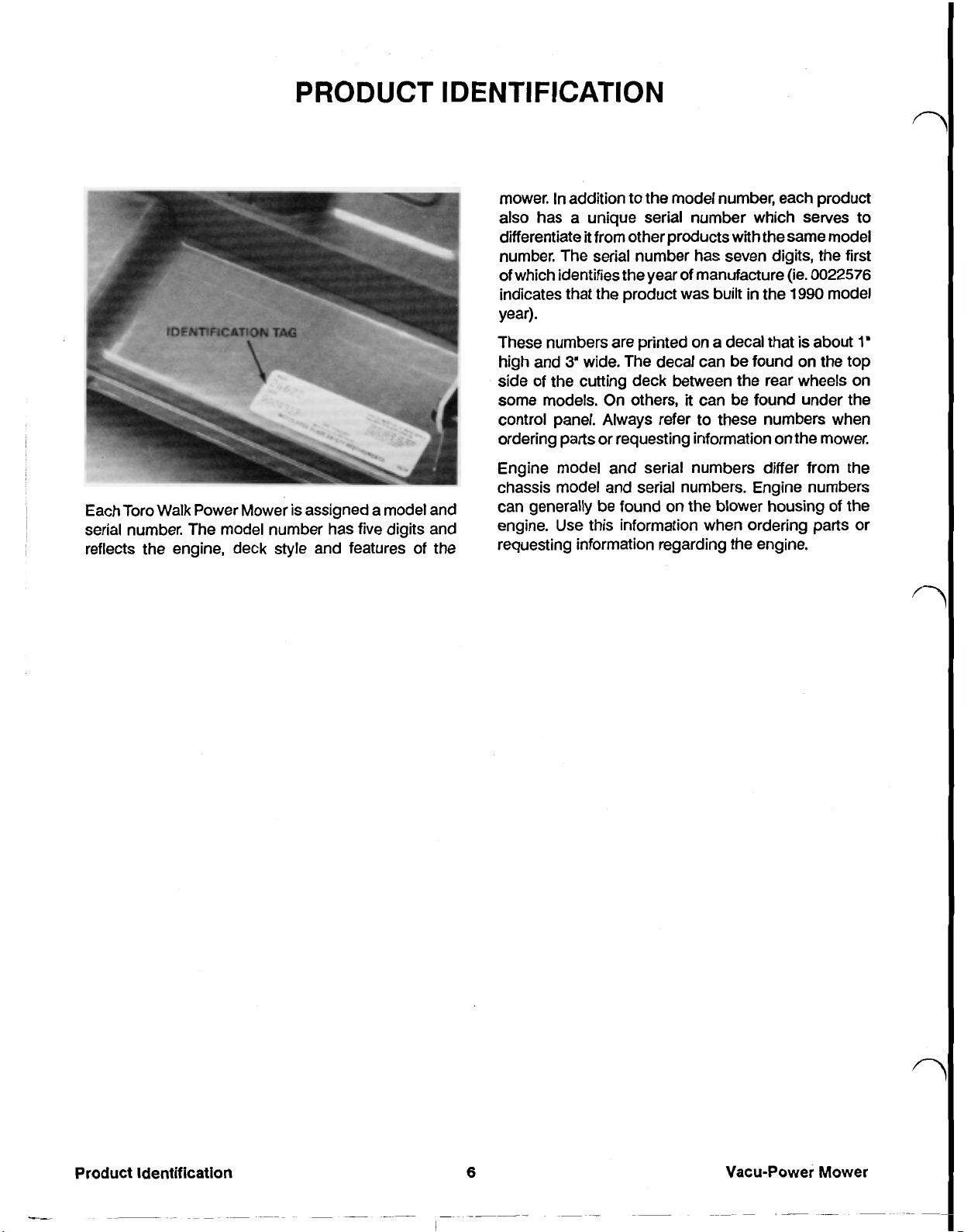
In
mower.
also
differentiate it from other products with the same model
number. The serial number has seven digits, the first
of which identifies the year
indicates that the product was built
year).
addition to the model number, each product
has a unique serial number which serves to
of
manufacture (ie.
in
the
0022576
1990
model
Each Toro Walk Power Mower is assigned a model and
serial number. The model number has five digits and
reflects the engine, deck style and features of the
These numbers are printed
high and
side of the cutting deck between the rear wheels on
some models. On others, it can be found under the
control panel. Always refer to these numbers when
ordering parts or requesting information on the mower.
Engine model and serial numbers differ from the
chassis model and serial numbers. Engine numbers
can generally be found
engine. Use this information when ordering parts
requesting information regarding the engine.
3'
wide, The decal can be found on the top
on
a decal that is about
on
the blower housing of the
1'
or
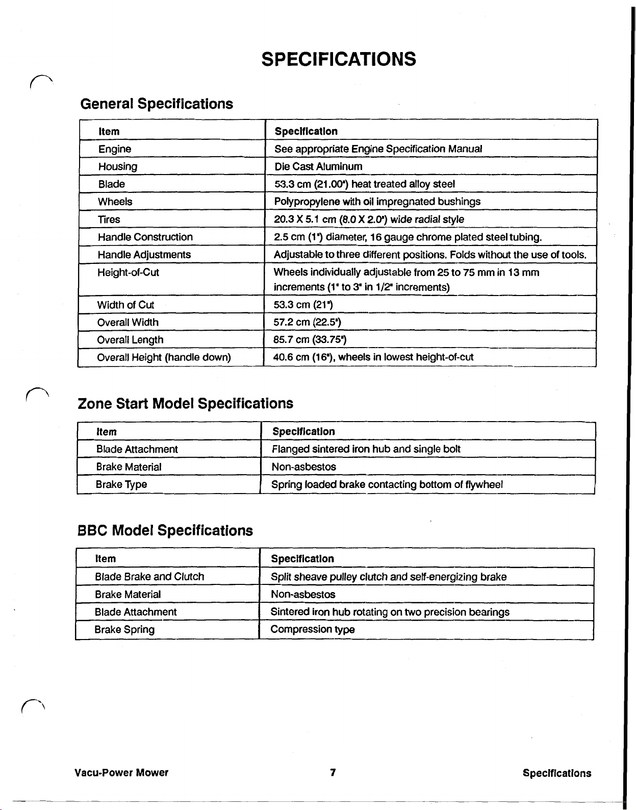
General Specifications
SPECIFICATIONS
Specification
See appropriate Engine Specification Manual
Die Cast Aluminum
53.3
cm
(21.00”)
Polypropylene with oil impregnated bushings
20.3
X
5.1
2.5
cm
(1”)
Adjustable to three different positions. Folds without the use of tools.
heat treated alloy steel
cm
(8.0
X
2.0')
wide radial style
diameter,
16
gauge chrome plated steel tubing.
n
Wheels individually adjustable from
increments
53.3
57.2
85.7
40.6
cm
cm
cm
cm
I
Width
of
Cut
Overall Width
Overall Length
Overall Height (handle down)
Zone Start Model Specifications
item
Blade Attachment
Brake Material
Brake Type
BBC
Model Specifications
Specification
Flanged sintered iron hub and single bolt
Non-asbestos
Spring loaded brake contacting bottom of flywheel
(1'
to
3'
in
(21”)
(22.5'”)
(33.753
(16”)
wheels
25
1/2’
increments)
in
lowest height-of-cut
to
75
mm
in
13
mm
I
I
I
Blade Brake and Clutch
Blade Attachment
Brake Spring
Vacu-Power Mower Specifications
Split sheave pulley clutch and self-energizing brake
Non-asbestos Brake Material
two
Sintered iron hub rotating on
Compression
type
7
precision bearings
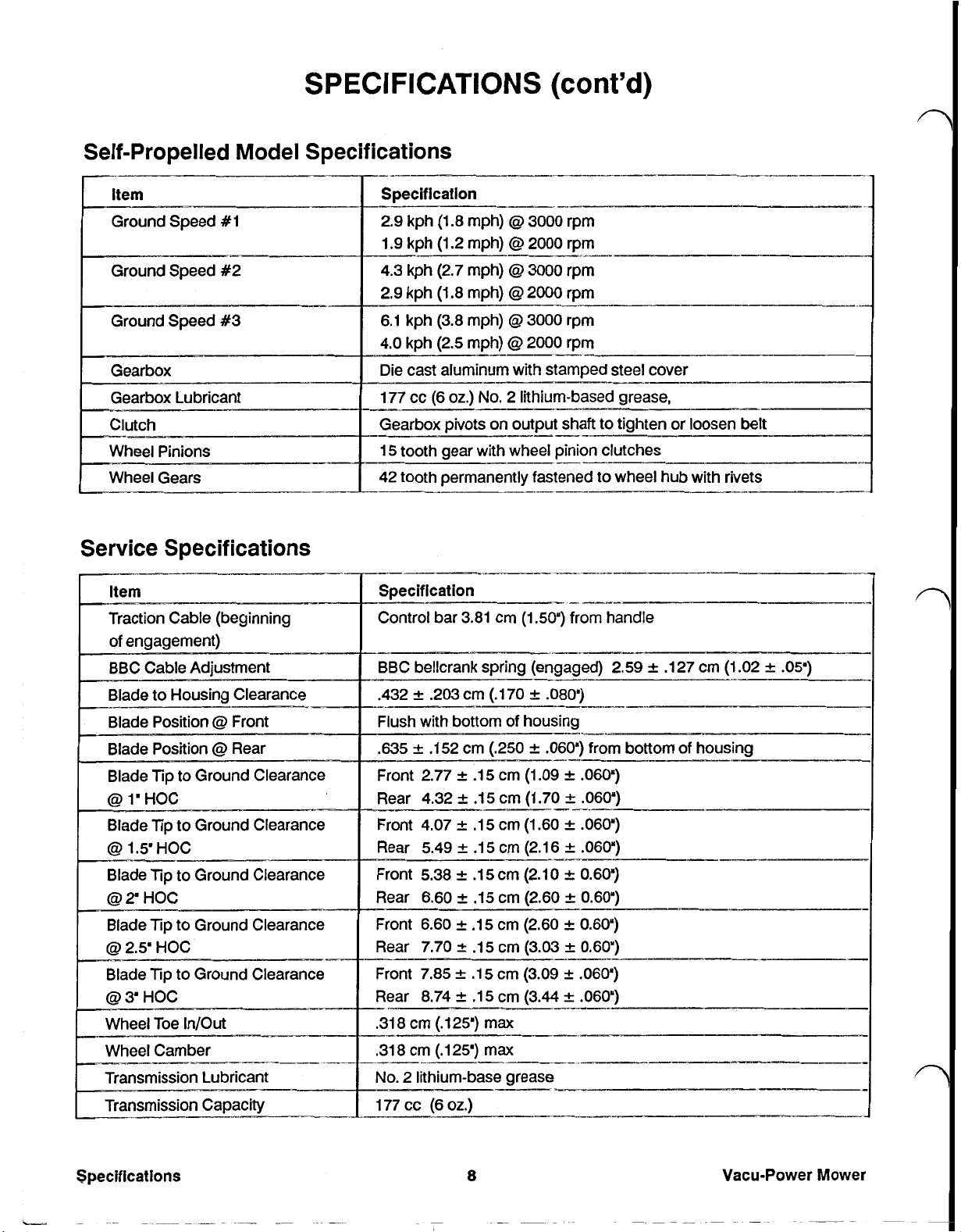
SPECIFICATIONS
Self-Propelled Model Specifications
Specification
2.9
kph (1.8 mph) 3000 rpm
1.9 kph (1.2 mph) 2000 rpm
Ground Speed #2
4.3 kph (2.7 mph) 3000 rpm
2.9 kph (1.8 mph) 2000 rpm
6.1 kph (3.8 mph) 3000 rpm
4.0 kph (2.5 mph)
Die cast aluminum with stamped steel cover
(cont'd)
I^-
2000
rpm
--__
Service Specifications
177 cc
Gearbox pivots on output shaft to tighten
15 tooth gear
42 tooth permanently fastened to wheel hub with rivets
specification
Control bar 3.81 cm
(6
oz.)
No.
2 lithium-based grease,
with
wheel
pinion clutches
(1.50”)
from handle
or
loosen belt
--
BBC bellcrank spring (engaged) 2.59 .127 cm (1.02
.432 .203 cm (.170
Flush with bottom of housing
.635
-
Front 2.77 .15 cm (1.09
Rear 4.32
Front 4.07 .15 cm (1.60
Rear 5.49 .15 cm (2.1 6
Front 5.38 A .15 cm (2.10 0.60")
Rear 6.60 .15 cm (2.60
.152 cm (.250
.I5
.080")
.060")
cm (1.70
---
--I-
from bottom of housing
.060")
,060")
.060")
.060”)
A
0.60")
I--
.05”)
Specifications
Ground Clearance
Front 6.60 .15 cm (2.60
Rear 7.70 .15 cm (3.03
Front 7.85 .15 cm (3.09
Rear 8.74 .15 cm (3.44
.318 cm (.125') max
,318 cm 125') max
No.
2 lithium-base grease
177 cc
(6
oz.)
8
0.60")
0.60')
.060")
.060”)
-I__-
Vacu-Power Mower
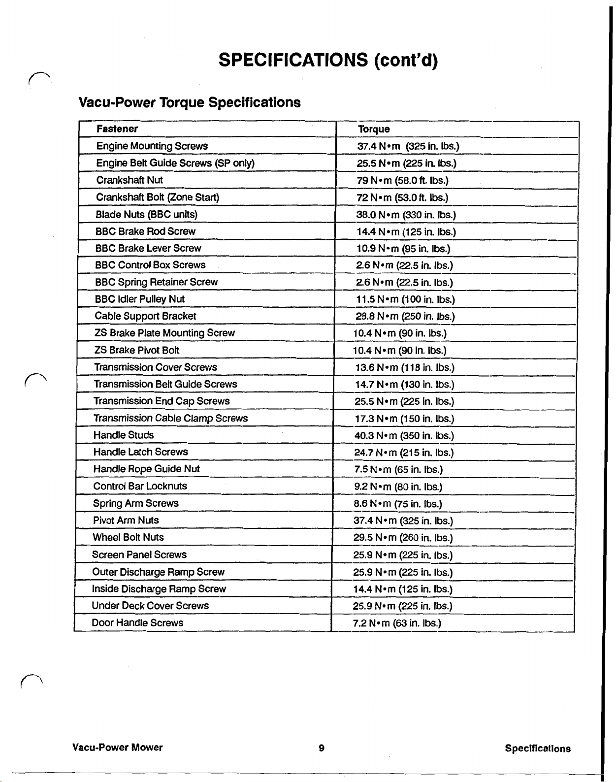
SPECIFICATIONS
Vacu-Power Torque Specifications
(cont'd)
8.6
N-m
(75
in.
Ibs.)
Vacu-Power Mower
9
Specifications
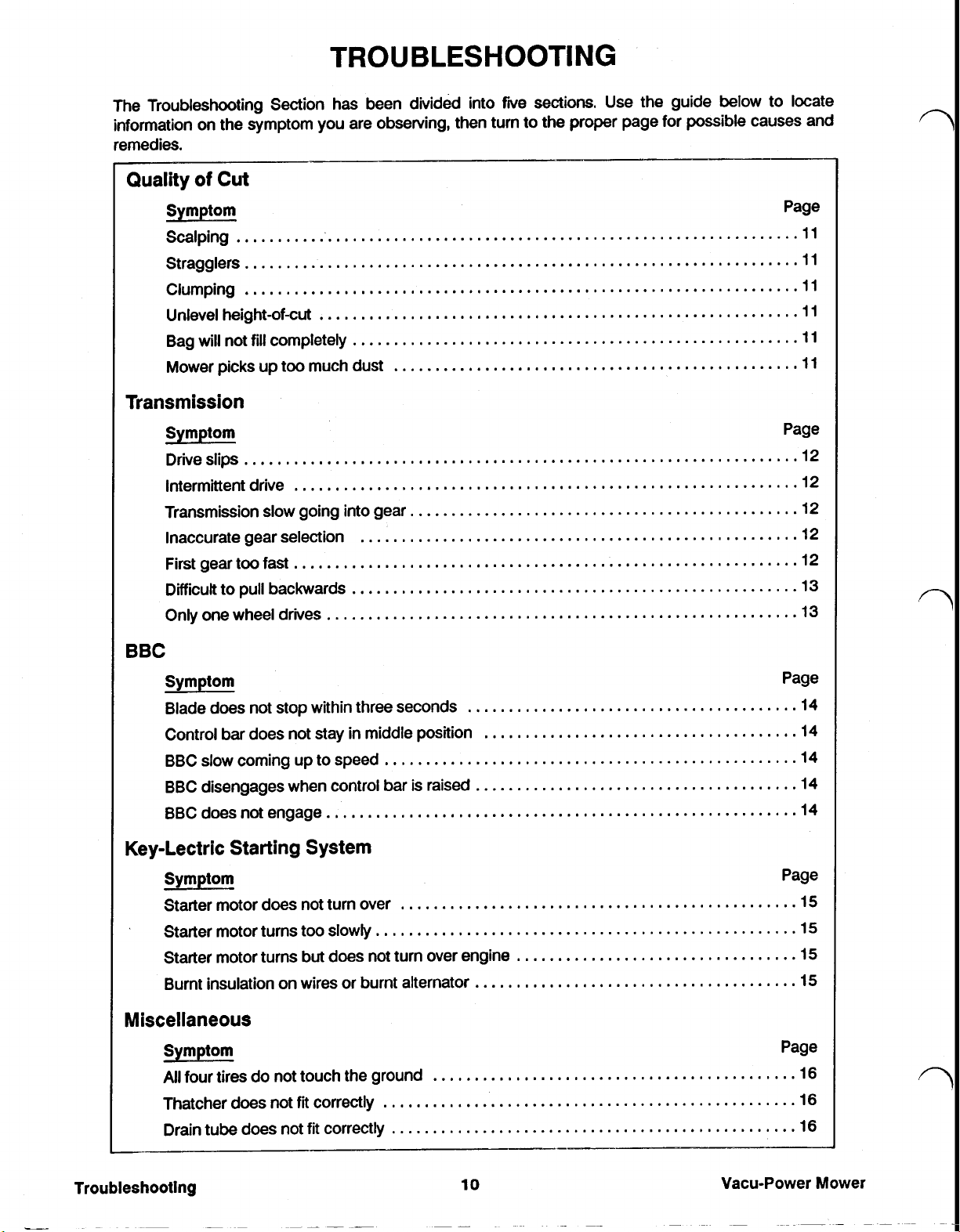
TROUBLESHOOTING
The Troubleshooting Section has been divided into
information on the symptom you are observing. then turn to the
remedies
Scalping 11
Stragglers
Clumping
Unlevel height-of-cut
Bag will not
Mower picks up too much dust
...................................................................
...................................................................
..........................................................
fill
completely
......................................................
.................................................
five
sections Use the guide below to locate
Transmission
Symptom
Drive slips
lntermittent
Transmission slow going into gear
Inaccurate gear selection
...................................................................
drive
.............................................................
...............................................
.....................................................
proper
page for possible causes and
Page
11
11
11
11
11
Page
12
12
12
12
First gear too fast
Difficult to pull backwards
Only one wheel drives
st
.............................................................
......................................................
.........................................................
BBC
Symptom
Blade does not stop within three seconds
in
Control bar does not stay
BBC slow coming up to speed
BBC disengages when control bar is raised
BBC does not engage
middle position
..................................................
.........................................................
Key-Lectric Starting System
Symptom
Starter motor does not turn over
Starter motor turns too slowly
Starter motor turns but does not turn over engine
Burnt insulation on wires
or
................................................
...................................................
burnt alternator
12
13
13
Page
........................................
......................................
.......................................
..................................
.......................................
14
14
14
14
14
Page
15
15
15
15
Miscellaneous
Symptom
All
four tires do not touch the ground
Thatcher
Drain tube does not
Troubleshooting
does
not
fit
correctly
fit
correctly
Page
............................................
..................................................
.................................................
10
Vacu-Power
16
16
16
Mower
TROUBLESHOOTING
(cont'd)
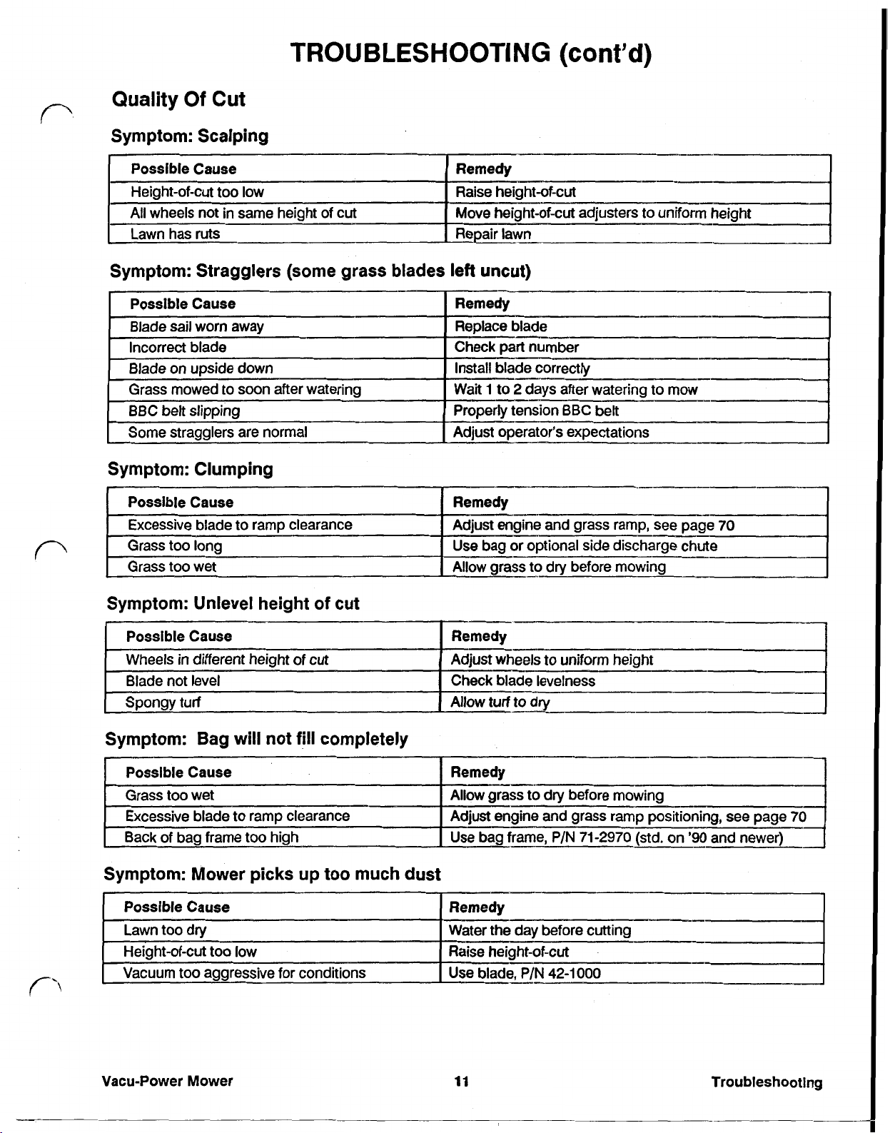
Quality
Of Cut
Symptom: Scalping
Symptom: Stragglers (some grass blades left uncut)
Symptom: Clumping
S
m tom: Bag
will
not
fill
completely
Symptom: Mower picks up too much
Possible Cause
Lawn too dry Water the day before cutting
too
Height-of-cut
Vacuum too aggressive
Vacu-Power Mower
low
for
conditions
dust
Remedy
Raise height-of-cut
Use blade.
11
P/N
42-1000
I
Troubleshooting
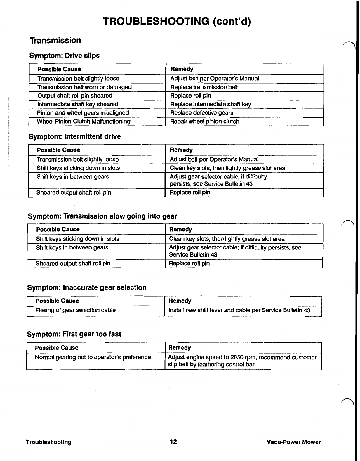
TROUBLESHOOTING
Transmission
Symptom: Drive slips
Possible Cause
Transmission
Transmission
[
Output shaft roll
ntermediate shaft key sheared
Pinion and wheel gears mis-aligned
Wheel Pinion Clutch Malfunctioning Repair wheel
Symptom: Intermittent drive
belt
slightly loose Manual
belt
worn or damaged
pin
sheared Replace roll
(cont'd)
pin
Replace intermediate shaft key
Replace defective gears
pinion
clutch
slow
Symptom: Transmission
Possible Cause
Shift keys sticking down
in
Shift keys
Sheared output shaft roll
between gears
in
pin
slots
going into gear
Symptom: Inaccurate gear selection
Possible Cause
of
Flexing
gear selection cable
Symptom: First gear too fast
Remedy
Clean key slots, then lightly grease
Adjust gear selector cable; if difficulty persists, see
Service Bulletin
Replace
Remedy
Install new shift lever and cable per
roll
43
pin
slot
area
Troubleshooting
12
Vacu-Power Mower
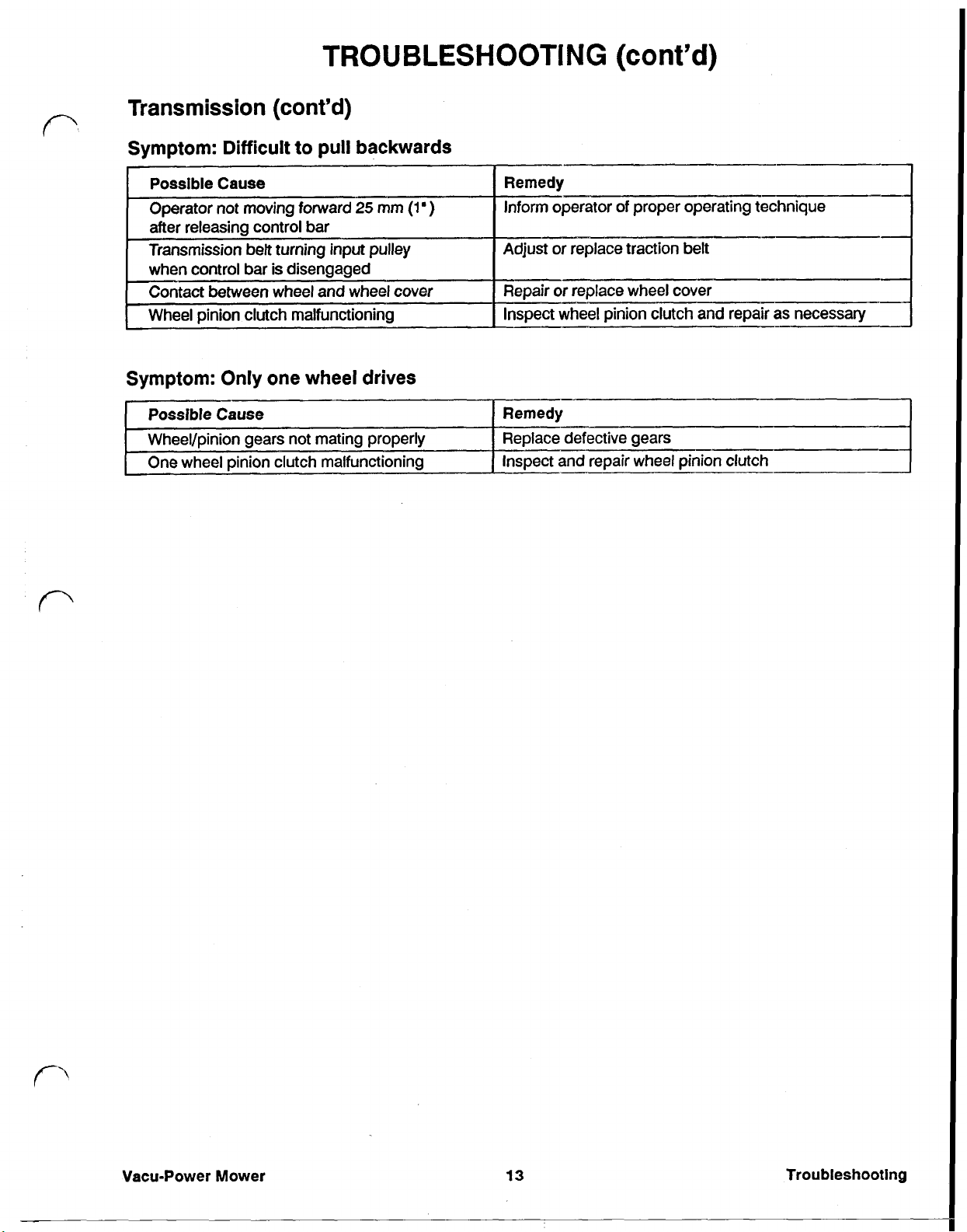
TROUBLESHOOTING
(cont'd)
Transmission
Symptom: Difficult
Possible
Operator not moving forward
after releasing control bar
Transmission belt
when control bar is disengaged
Contact between wheel and wheel cover
Wheel pinion clutch malfunctioning
Symptom: Only one wheel drives
Possible
Wheel/pinion gears not mating properly Replace defective gears
One wheel pinion clutch malfunctioning Inspect and' repair wheel pinion clutch
Cause
Cause
(cont'd)
to
pull backwards
25
turning
input
mm
pulley
(1
I
Remedy
)
Inform operator of proper operating technique
I
Adjust or replace traction belt
I
Repair or replace wheel cover
Inspect wheel pinion clutch and repair as necessary
Remedy
I
I
I
Vacu-Power
Mower
13
Troubleshooting
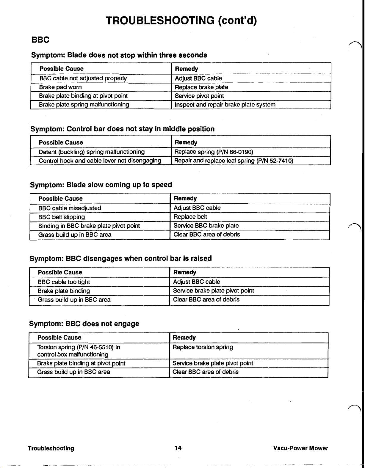
TROUBLESHOOTING
BBC
Symptom: Blade does not stop within three seconds
(cont’d)
Possible Cause
BBC cable not adjusted properly
-Brake pad worn
Brake plate spring malfunctioning
Remedy
Adjust BBC cable
Replace brake plate
Service pivot point Brake plate binding at pivot point
Inspect and repair brake plate system
Symptom: Control bar does not stay in middle position
Remedy
Detent (buckling) spring malfunctioning
Control hook and cable lever not disengaging
Replace spring (P/N
Repair and replace leaf spring (P/N
Symptom: Blade slow coming up to speed
Possible Cause Remedy
BBC cable mis-adjusted Adjust BBC cable
BBC belt slipping
Binding
Grass build
I
in
BBC brake plate pivot point
up
in BBC area
Replace belt
Service BBC brake plate
Clear BBC area of debris
66-0190)
52-7410)
1
I
I
I
I
Symptom: BBC disengages when control bar
Possible Cause
BBC cable too tight
binding
up
in
Grass build
BBC area Clear BBC area of debris
Remedy
Adjust BBC cable
Service brake plate pivot point Brake plate
Symptom: BBC does not engage
Possible Cause Remedy
Torsion spring (P/N
control box malfunctioning
Brake plate binding at pivot point
Grass
build
up
46-5510)
in
BBC area
in
Replace torsion spring
Service brake plate pivot point
Clear BBC area
is
raised
of
debris
I
Troubleshooting
14
Vacu-Power Mower
TROUBLESHOOTING
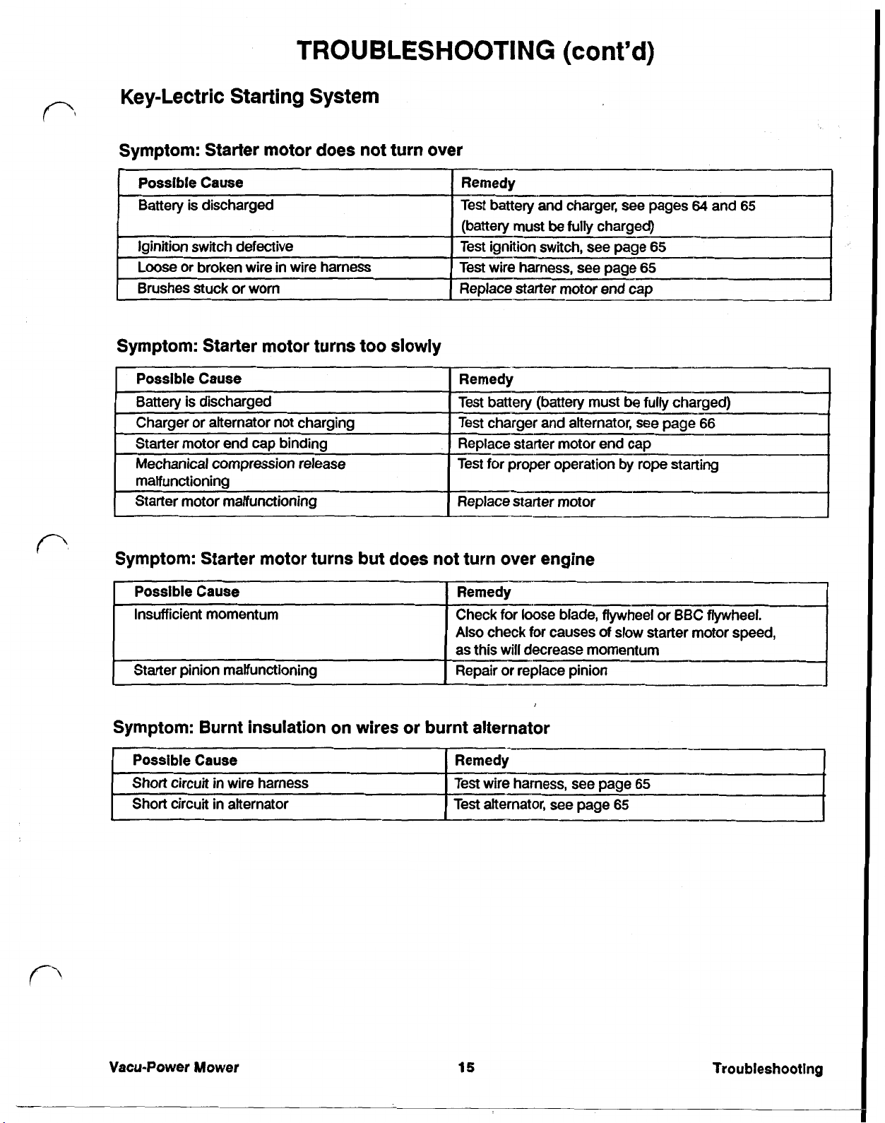
Key-Lectric Starting System
Symptom: Starter motor does not turn over
Symptom: Starter motor turns too slowly
(cont'd)
Symptom: Starter motor turns but does not turn over engine
[Possible Cause Remedy
Insufficient momentum Check for loose blade, flywheel
Also
check
for
causes
will
as this
Starter pinion malfunctioning Repair
decrease momentum
or
replace pinion
Symptom: Burnt insulation on wires or burnt alternator
Possible Cause
Short circuit in wire harness Test wire harness, see page
Short circuit in alternator Test alternator, see page
of
or
BBC flywheel.
slow
starter motor speed,
65
65
Vacu-Power Mower
15
Troubleshootlng
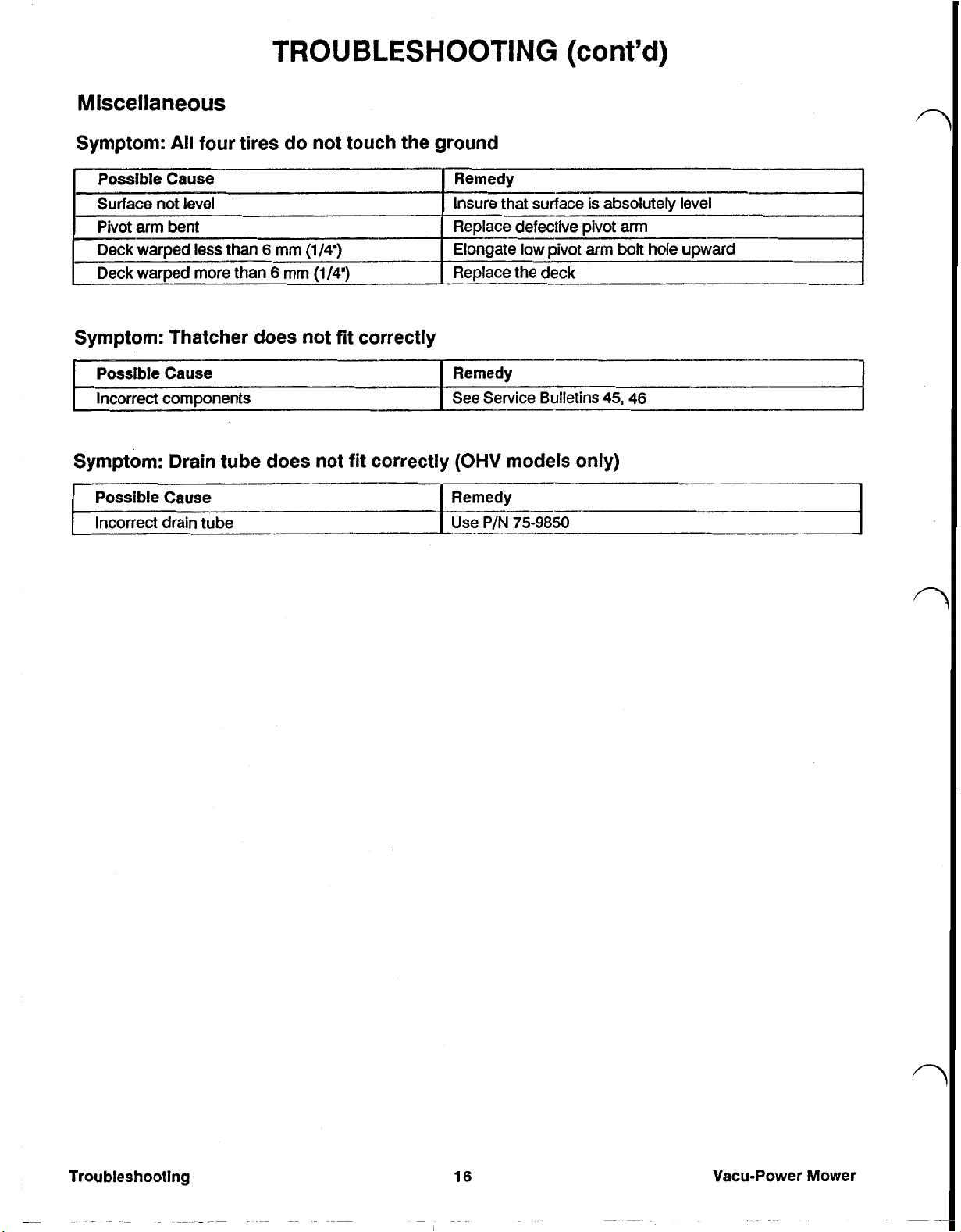
Miscellaneous
TROUBLESHOOTING
(cont’d)
Symptom:
All
four tires
do
not touch the ground
Symptom: Thatcher does not fit correctly
Possible Cause
Incorrect
components
Symptom: Drain tube does not fit correctly
Possible Cause Remedy
Incorrect drain tube
Remedy
See Service Bulletins
(OHV
45, 46
models only)
Vacu-Power
Mower
MAINTENANCE
TECUMSEH 2-CYCLE ENGINE
Tecumseh 2-Cycle Servicing the Air Cleaner
Normally, clean the air cleaner after every
hours. More frequent cleaning is required when the
in
dusty
or
mower is operated
ditty conditions.
25
operating
5.
Clean the top side of the base and the inside of
cover thoroughly. Clean the filter by tapping on
a
solid surface
6.
Reinstall the paper filter and the
nut
finger tight and then turn one
complete turn.
nut.
lighten the
(1)
more
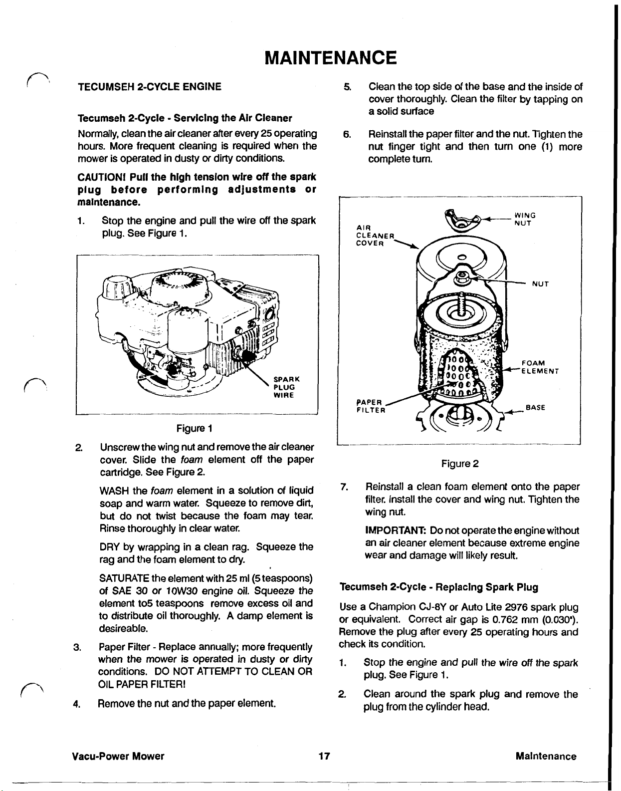
CAUTION! Pull the high tension wire
plug before performing adjustments or
maintenance.
1. Stop the engine and pull the wire
plug. See Figure 1.
Figure
2.
Unscrew the wing
cover. Slide the
cartridge. See Figure
WASH the
soap and warm water. Squeeze to remove
but
do not twist because the foam may tear.
Rinse thoroughly
DRY
rag and the foam element to dry.
foam
by wrapping
element
1
nut
and remove the air cleaner
foam
element
2.
in
in
clear water.
in
a clean rag. Squeeze the
off
the spark
off
the spark
off
the paper
a solution of liquid
dirt,
Figure
7.
Reinstall a clean foam element onto the paper
filter. Install the cover and wing
wing
nut.
IMPORTANT:
an air cleaner element because extreme engine
wear and damage will likely result.
Do
2
nut.
lighten the
not operate the engine without
SATURATE the element with
of
SAE
30
or
10W30 engine
element to5 teaspoons remove excess oil and
to
distribute oil thoroughly. A damp element
desireable.
3. Paper Filter Replace annually: more frequently
when the mower is operated
conditions.
OIL PAPER FILTER!
4.
Remove the
Vacu-Power Mower
DO
NOT ATTEMPT TO CLEAN
nut
and the paper element.
25
ml
5 teaspoons)
oil.
Squeeze the
in
dusty or
dirty
OR
is
Tecumseh 2-Cycle Replacing Spark Plug
Use a Champion CJ-8Y
or
equivalent. Correct air gap
Remove the plug after every
check its condition.
1.
Stop the engine and
plug. See Figure
2.
Clean around the spark plug
plug
from the
17
or
1.
cylinder
Auto Lite
is
0.762
25
operating hours and
pull
the wire
head.
2976
spark plug
mm
(0.030'”)
off
the spark
and
remove the
Maintenance
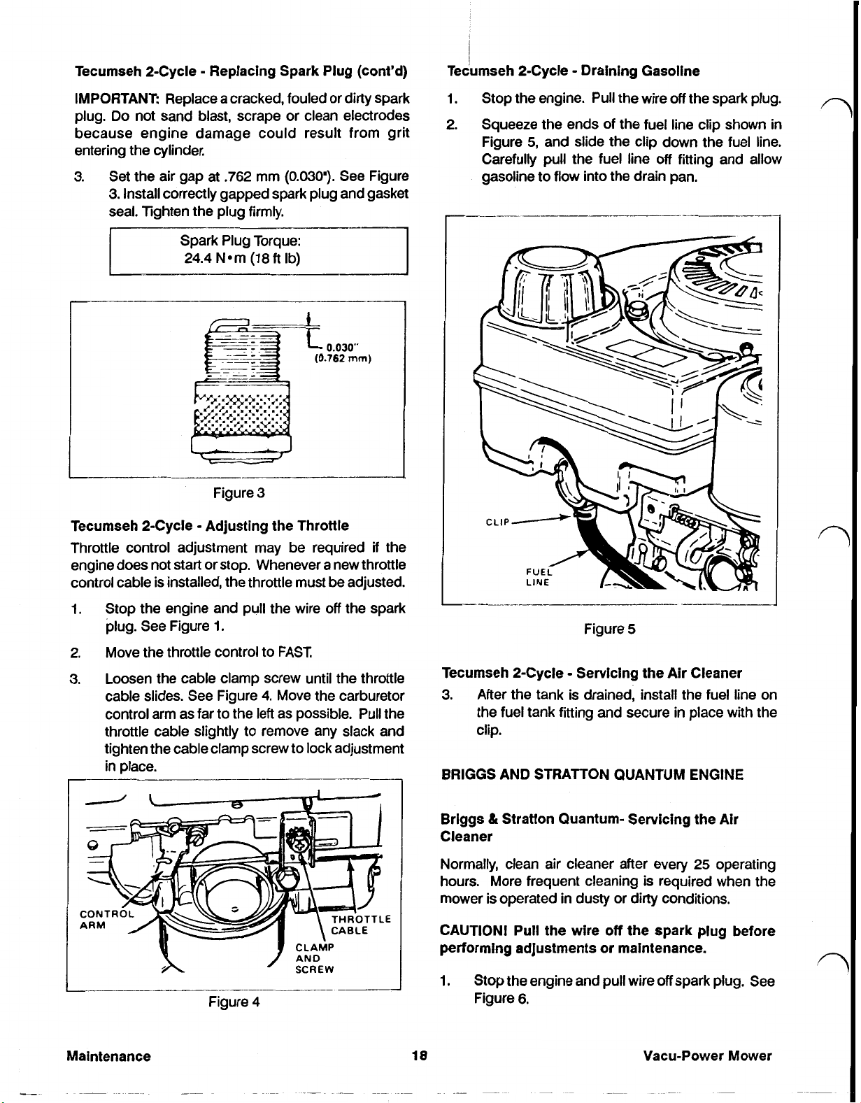
Tecumseh 2-Cycle Replacing Spark Plug (cont'd)
IMPORTANT: Replace a cracked, fouled or dirty spark
Do
plug.
because engine damage could result from grit
entering the cylinder.
3.
not sand blast, scrape or clean electrodes
Set the air gap at
3.
Install correctly gapped spark plug and gasket
seal. Tighten the plug firmly.
.762
mm
(0.030”).
See Figure
i
Tecumseh 2-Cycle Draining Gasoline
1.
Stop the engine. Pull the wire
2.
Squeeze the ends of the fuel line clip shown
Figure
Carefully
gasoline to flow into the drain pan.
5,
and slide the clip down the fuel line.
pull
the fuel line
off
the spark plug.
off
fitting
in
and allow
Figure
Tecumseh 2-Cycle Adjusting the Throttle
Throttle control adjustment may be required
engine does not start or stop. Whenever a new throttle
control cable is installed, the throttle must be adjusted.
1.
Stop the engine and pull the wire
plug. See Figure
2.
Move the throttle control to
3.
Loosen the cable clamp screw until the throttle
cable slides. See Figure
control arm as far to the left as possible. Pull the
throttle cable slightly to remove any slack and
tighten the cable clamp screw to lock adjustmel
in
place.
1.
3
off
the spark
FAST,
4.
Move the carburetor
if
the
Tecumseh 2-Cycle Servicing the Air Cleaner
3.
It
BRIGGS AND STRATTON QUANTUM ENGINE
Brlggs Stratton Quantum- Servicing the Air
Cleaner
Normally, clean air cleaner after every
hours. More frequent cleaning is required when
mower
After the tank is drained, install the fuel line on
fitting
the fuel tank
clip.
is
operated
and secure
in
dusty or dirty conditions.
in
place with the
25
operating
the
CAUTION!
performing adjustments or maintenance.
18
Pull
the wire
Stop the engine and pull wire
Figure
6.
off
the spark plug before
off
spark plug. See
Vacu-Power Mower
2.
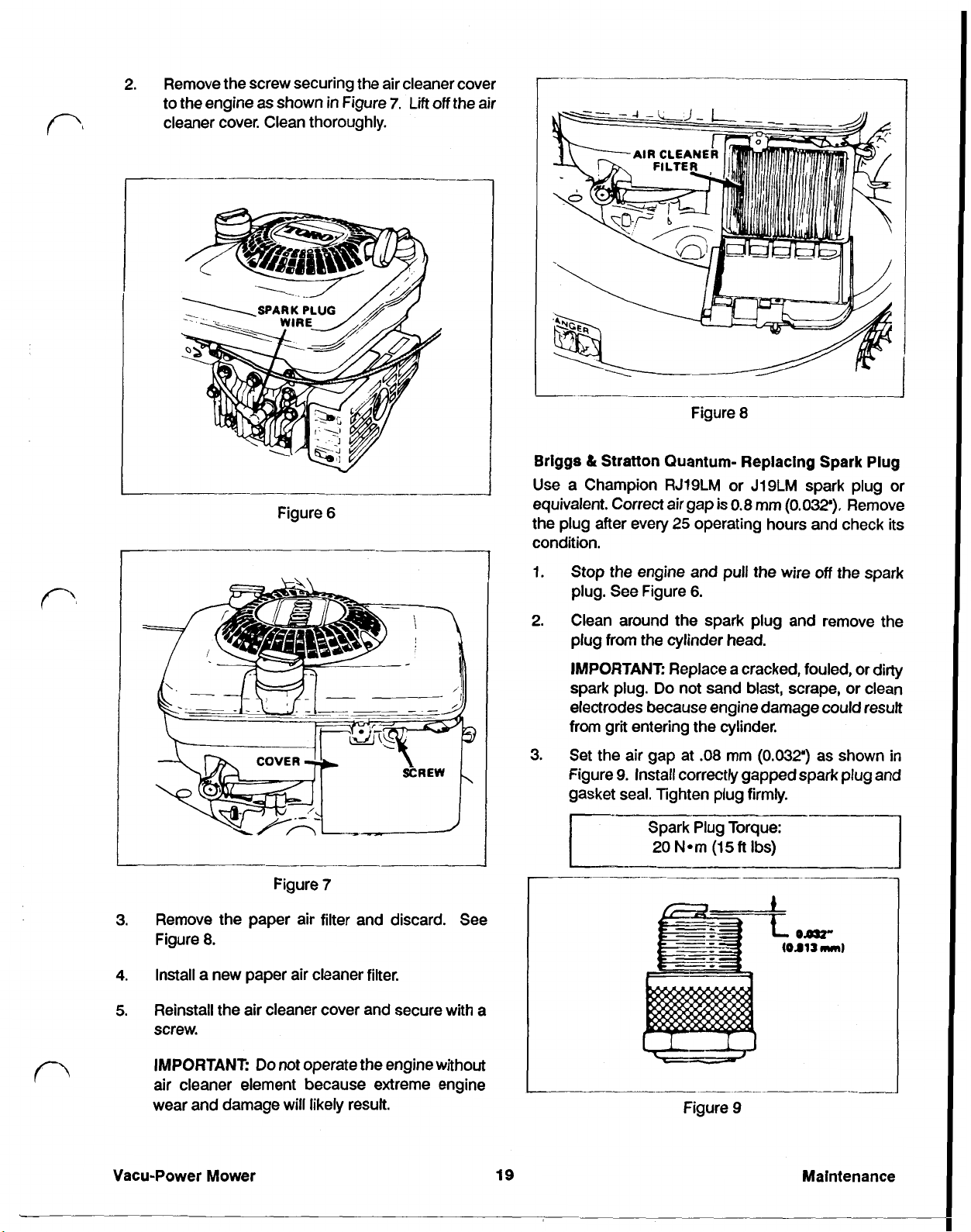
Remove the screw securing the air cleaner cover
to the engine
as
shown
in
Figure
7.
cleaner cover. Clean thoroughly.
Lift
off
the air
Figure
Briggs & Stratton Quantum- Replacing Spark Plug
I
Figure
6
Use a Champion RJ19LM or J19LM spark plug or
equivalent. Correct air gap is
the plug after every
25
8
0.8
mm
(0.032").
Remove
operating hours and check its
condition.
1.
Stop the engine and
plug. See Figure
2.
Clean around the spark plug and remove the
6.
pull
the wire
off
the spark
plug from the cylinder head.
IMPORTANT:
spark plug.
Replace a cracked, fouled, or dirty
Do
not sand blast, scrape, or clean
electrodes because engine damage could result
from grit entering the cylinder.
3.
Set the air gap at
Figure
9.
Install correctly gapped spark plug and
.08
mm
(0.032")
as shown
in
gasket seal. Tighten plug firmly.
Spark Plug Torque:
20
(15
ft
Ibs)
Figure
3.
Remove the paper air filter and discard. See
Figure
4.
Install a new paper air cleaner filter.
5.
Reinstall the air cleaner cover and secure with a
8.
7
screw.
IMPORTANT:
Do
not operate the engine without
air cleaner element because extreme engine
wear and damage will likely result.
Vacu-Power
Mower
19
Figure
9
Maintenance
Briggs & Stratton Quantum- Dralnlng Gasoline
1.
Stop the engine and pull the wire off the spark
in
plug as shown
Figure
6.
NOTE: Drain gasoline from a cold engine only.
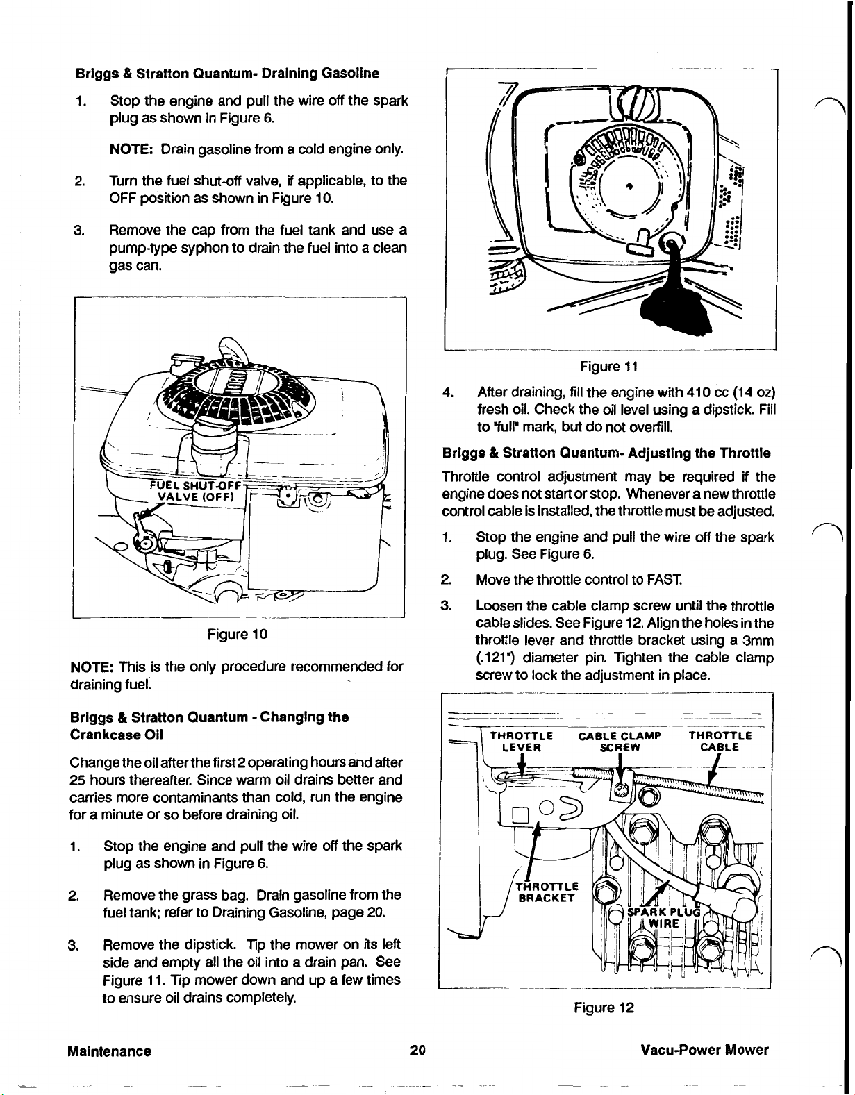
2.
Turn the fuel shut-off valve,
OFF position
as
shown
if
applicable, to the
in
Figure
IO.
3. Remove the cap from the fuel tank and use a
pump-type syphon to drain the fuel into a clean
gas can.
n
NOTE: This is the only procedure recommended for
draining fuel:
&
Briggs
Crankcase
Stratton Quantum Changing the
Oil
Change the oil after the first 2 operating hours and after
25
hours thereafter. Since warm oil drains better and
carries more contaminants than cold, run the engine
for a minute or
so
before draining oil.
4.
After draining,
Figure
fill
I
I
the engine with
410
cc
(14
oz)
fresh oil. Check the oil level using a dipstick. Fill
to “full” mark,
&
Briggs
Stratton Quantum- Adjusting the Throttle
Throttle control adjustment may
but
do not overfill.
be
required
if
the
engine does not start or stop. Whenever a new throttle
control cable is installed, the throttle must be adjusted.
1.
Stop the engine and
plug. See Figure
2.
Move the throttle control to FAST.
3.
Loosen the cable clamp screw until the throttle
cable slides. See Figure
6.
pull
the wire off the spark
12.
Align the holes
in
the
throttle lever and throttle bracket using a 3mm
(.121”)
screw to lock the adjustment
diameter pin. Tighten the cable clamp
in
place.
THROTTLE CABLE
LEVER SCREW CABLE
CLAMP
THROTTLE
1.
Stop the engine and pull the wire off the spark
plug as shown
2.
Remove the grass bag. Drain gasoline from the
in
Figure
6.
fuel tank; refer to Draining Gasoline, page
3.
Remove the dipstick.
Tip
the mower on its left
side and empty all the oil into a drain pan. See
11.
Tip
Figure
mower down and up a few times
to ensure oil drains completely.
20.
Vacu-Power Mower
TORO 2-CYCLE ENGINE
TORO 2-Cycle Replacing the Spark Plug
TORO 2-Cycle Servicing the Air Cleaner
Normally, clean the air cleaner foam element after
every
25
operating hours. More frequent cleaning is
required when the mower is operated
in
dusty or dirty
conditions.
CAUTION !
orming adjustments or maintenance.
1. Stop the engine and pull the wire
Pull
wire
off
spark plug before perf-
off
the spark
Plug.
2.
Lift
tabs at top of air cleaner cover and pivot the
cover down. Clean the cover thoroughly.
If
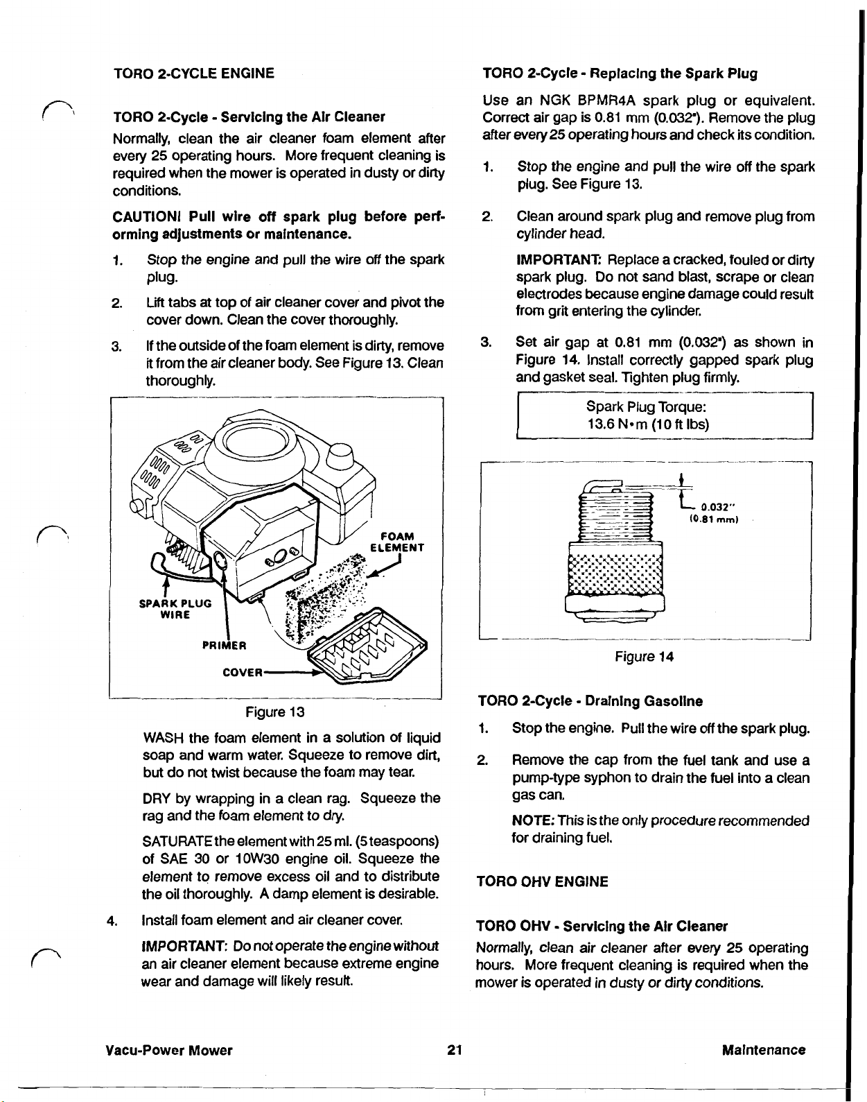
3.
the outside of the foam element is dirty, remove
it
from the air cleaner body. See Figure 13. Clean
thoroughly.
Use an
Correct air gap is 0.81 mm
after every
1.
NGK
BPMR4A spark plug or equivalent.
(0.032”)
25
operating hours and check
Remove the plug
Stop the engine and pull the wire
its
condition.
off
the spark
plug. See Figure 13.
2.
Clean around spark
plug
and
remove plug from
cylinder head.
IMPORTANT
spark plug.
Replace a cracked, fouled or dirty
Do
not sand blast, scrape or clean
electrodes because engine damage could result
from grit entering the cylinder.
3. Set air gap at 0.81 mm
Figure
and
14.
Install correctly gapped spark plug
gasket seal. Tighten plug firmly.
(0,032”)
as
shown
in
Figure 13
WASH
the foam element
in
a solution of liquid
soap and warm water. Squeeze to remove
but do not twist because the foam may tear.
DRY
by wrapping
in
a clean rag. Squeeze the
rag and the foam element to dry.
25
ml.
(5
SATURATE the element with
teaspoons)
of SAE 30 or 1OW30 engine oil. Squeeze the
element to remove excess oil and to distribute
A
the oil thoroughly.
4.
Install foam element and air cleaner cover.
IMPORTANT:
damp element is desirable.
Do not operate the engine without
an air cleaner element because extreme engine
wear and damage will likely result.
Vacu-Power Mower
dirt,
TORO 2-Cycle Draining Gasoline
1. Stop the engine. Pull the wire
2.
Remove the cap from the fuel tank and use a
off
the spark plug.
pump-type syphon to drain the fuel into a clean
gas can.
NOTE:
This is the only procedure recommended
for draining fuel.
TORO OHV ENGINE
TORO OHV Servicing the Alr Cleaner
Normally, clean air cleaner after every
25
hours. More frequent cleaning is required when the
mower is operated
21
in
dusty or dirty conditions.
Maintenance
operating
 Loading...