

Page 1
ENTER
SENTINEL®
AlarmBAHold Irrigation
Home/Back Manual
Option
Watering
Scheduled
Watering
Diagnostics
& Alarms
Station Settings
Satellite SettingsStopHelpStart
Page 2

Table of Contents
1 . . . . . . . .Chapter 1: Sentinel Control Module
1 . . . . . . . . . . . . . . . .I. Control Module Overview
2 . . . . . . . . . . . . . . . . . . . . . . . Control Module Display
2 . . . . . . . . . . . . . . . . . . . . . . . Front LEDs
3 . . . . . . . . . . . . . . . . . . . . . . . Controls
5 . . . . . . . . . . . . . . . . . . . . . . . Ports
7 . . . . . . . . . . . . . . . II. Programming Overview & Navigation
9 . . . . . . . . . . . . . . . . . . . . . Icons Explained
10 . . . . . . . Chapter 2: Basic Controller Programming
10 . . . . . . . . . . . . . . . I. Satellite Settings
10 . . . . . . . . . . . . . . . . . . . . . . . Time & Day
11 . . . . . . . . . . . . . . . . . . . . . . . ET
11 . . . . . . . . . . . . . . . . . . . . . . . Language
12 . . . . . . . . . . . . . . . . . . . . . . . Flow Processing
12 . . . . . . . . . . . . . . . . . . . . . . . Flow Factors Meter 2
13 . . . . . . . . . . . . . . . . . . . . . . . Flow Factors Meter 1
13 . . . . . . . . . . . . . . . . . . . . . . . N/O Master
14 . . . . . . . . . . . . . . . . . . . . . . . Station Count
14 . . . . . . . . . . . . . . . . . . . . . . . Unit Code
15 . . . . . . . . . . . . . . . . . . . . . . . Day Change Hour
16 . . . . . . . . . . . . . . . .II. Scheduled Watering
17 . . . . . . . . . . . . . . . . . . . . . . . Start Times
17 . . . . . . . . . . . . . . . . . . . . . . . Prog ET Toggle
18 . . . . . . . . . . . . . . . . . . . . . . . Clear Schedule
18 . . . . . . . . . . . . . . . . . . . . . . . Schedule Length
19 . . . . . . . . . . . . . . . . . . . . . . . Run Days
19 . . . . . . . . . . . . . . . . . . . . . . . Program Clear
20 . . . . . . . . . . . . . . . . . . . . . . . Rain O Days
20 . . . . . . . . . . . . . . . . . . . . . . . Assigned Schedule
21 . . . . . . . . . . . . . . . . . . . . . . . Water Window
21 . . . . . . . . . . . . . . . . . . . . . . . Continuous Run
22 . . . . . . . . . . . . . . . .. . . . . . . . .Repeat Delay Time
22 . . . . . . . . . . . . . . . . . . . . . . . .Repeats
23 . . . . . . . . . . . . . . . . . . . . . . . .Percent Scale
23 . . . . . . . . . . . . . . . . . . . . . . . .Slot-Station-Time
25 . . . . . . . .Chapter 3: Advanced Programming
25 . . . . . . . . . . . . . . . .I. Manual Watering
25 . . . . . . . . . . . . . . . . . . . . . . . .Manual
26 . . . . . . . . . . . . . . . . . . . . . . . .Start / Stop Program
26 . . . . . . . . . . . . . . . .II. Stop Menu
26 . . . . . . . . . . . . . . . . . . . . . . . .Full Shutdown
27 . . . . . . . . . . . . . . . . . . . . . . . .All Manuals O
27 . . . . . . . . . . . . . . . . . . . . . . . .All Autos O
28 . . . . . . . . . . . . . . . .III. Alarms Menu
28 . . . . . . . . . . . . . . . . . . . . . . . .Show Alarms & Warnings
28 . . . . . . . . . . . . . . . . . . . . . . . .Clear Sat. Alarms
29 . . . . . . . . . . . . . . . . . . . . . . . .Clear Comm. Alarms
29 . . . . . . . . . . . . . . . . . . . . . . . .Clear Elec. Alarms
30 . . . . . . . . . . . . . . . . . . . . . . . .Clear Flow Alarms
30 . . . . . . . . . . . . . . . . . . . . . . . .Show Moisture Data
31 . . . . . . . . . . . . . . . .IV. Station Settings
31 . . . . . . . . . . . . . . . . . . . . . . . .Plant Factor
31 . . . . . . . . . . . . . . . . . . . . . . . .Station Days O
32 . . . . . . . . . . . . . . . . . . . . . . . .Maximum Flows
32 . . . . . . . . . . . . . . . . . . . . . . . .Expected Flows
33 . . . . . . . . . . . . . . . . . . . . . . . .Map Stations
34 . . . . . . . . . . . . . . . . . . . . . . . .Station Type
35 . . . . . . . . . . . . . . . . . . . . . . . .Precipitation Rate
36 . . . . . . . .Frequently Asked Questions
37 . . . . . . . .Troubleshooting Guide
38 . . . . . . . .Toro Warranty and Dedication to Quality
39 . . . . . . . .Notes
39 . . . . . . . .FCC Statement
ii
Page 3
Chapter 1: Sentinel Control Module
I. Overview
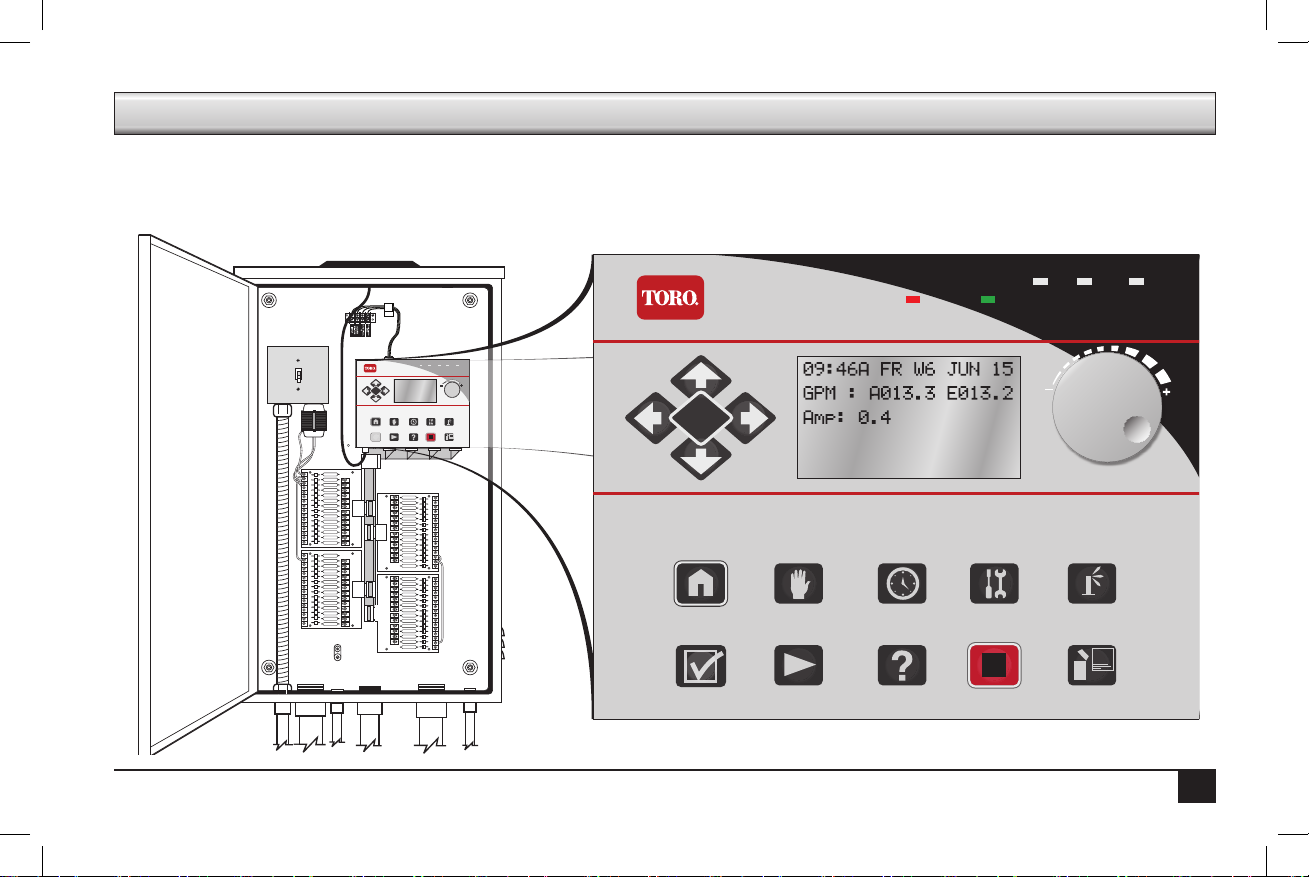
e Sentinel Control Module is the heart and brains of the Sentinel system. is overview will discuss the LCD screen, the Control Knob, and
the buttons.
SENTINEL
ENTER
Home/Back Manual
SENTINEL
Alarm Hold Irrigation
Scheduled
Diagnostics
Station Settings
Watering
Watering
& Alarms
Satellite SettingsStopHelpStart
ENTER
Home/Back Manual
Option
Watering
Scheduled
Watering
Diagnostics
Alarm Hold Irrigation
& Alarms
Station Settings
Satellite SettingsStopHelpStart
1
BA
Page 4
Control Module Display
Irrigation
1
2
3
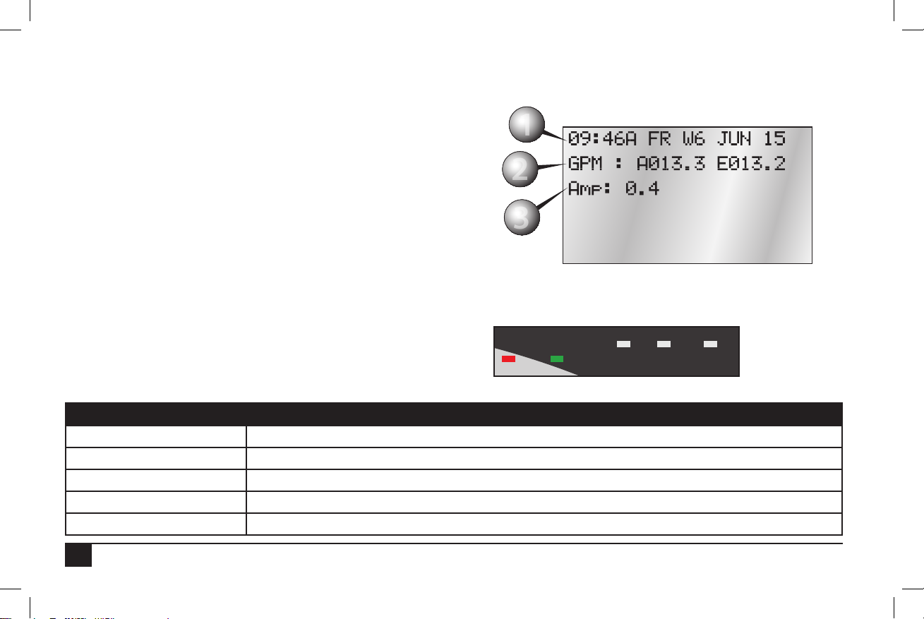
e Sentinel Controller has a six-line LCD screen. When rst powered on,
the display will be in its standard mode.
1. Current time (HH:MM), day, week number of schedule (up to six
weeks), and date.
2. If running, Actual ow (A#####) and Expected ow (E#####).
• Actual Flow: 5-digit numeric indicator of current ow through
connected ow sensor.
• Expected Flow: 5-digit numeric indicator of expected ow
based on current stations operating and their expected ows.
3. Current amperage draw
Front LEDs
e front of the Sentinel Control Module has ve LEDs to alert
the user to particular conditions.
LED Purpose
A Flow 1 activity. Light turns o within a couple minutes of no ow input.
B Flow 2 activity. Light turns o within a couple minutes of no ow input.
Alarm (Red) Flashing light if any alarm; steady light if any warnings.
Hold (Amber) A steady light indicates program or station days o.
Irrigation (Green) Steady light on if an irrigation program is currently running.
e Sentinel system takes rougly fteen (15) seconds to display information up once plugged in. Please be patient.
1
2
3
A B
Alarm
Hold
2
Page 5
Controls
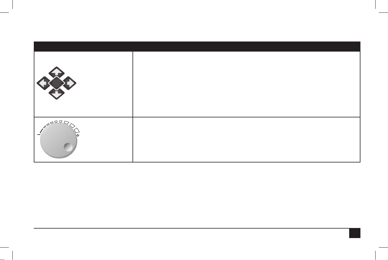
ere is one Control Knob and fteen (15) buttons to operate the Sentinel Controller.
Control Function
LEFT / RIGHT Arrows:
1) Move through the dierent menus on the controller
2) Within a menu line, move through the changeable elds.
UP / DOWN Arrows:
ENTER
Arrows and ENTER
Control Knob
1) Navigate through menu items
2) Navigate from one submenu line to another.
Note: Holding down an arrow button auto-repeats.
ENTER:
Press to enter a selected menu or to save a setting.
Rotate the Knob to change the value of the eld the cursor is on. Pressing the knob in is the
same functionality as the ENTER key.
3
Page 6
Button Function
Home/Back
Manual Watering
Scheduled Watering
Diagnostics & Alarms
Station Settings
Option
Start
Help
Stop
Satellite Settings
Returns the user to the previous screen (a “back” button) or to the Home screen.
Enter manual irrigation mode and manually start and stop programs.
Allows the user to program scheduled irrigation programs.
Access the Diagnostics and Alarms menu system to identify and clear alarms.
Access the Station Settings menu system.
For future functionality.
Start station or program.
Accesses the Sentinel Help system (future feature).
Enters the Stop menu, allowing full shutdowns and more.
Accesses settings for the satellite, such as time, day, language, and much more.
4
Page 7
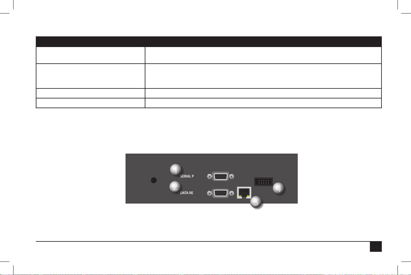
Ports
2
1
3
4
Top Ports Purpose
1. Serial Port (9-pin connector) Both top and bottom serial ports support communications devices, standard o-the-shelf serial
cables, and are optically isolated.
2. Data Retrieval port (9-pin connector) Works with existing Sentinel data retrieval cables and ow/ET/Rain pulse simulator devices.
New cables will allow access to 1 additional ow and 1 additional alarm input. Both ow
inputs support mixed mode use with ow, ET or Rain pulse devices.
3. Network RJ-45 port (option) To connect to a network.
4. (10-pin connector) UHF radio connection
1
SERIAL PORT
2
DATA RETRIE VAL
4
3
5
Page 8
223344556
1
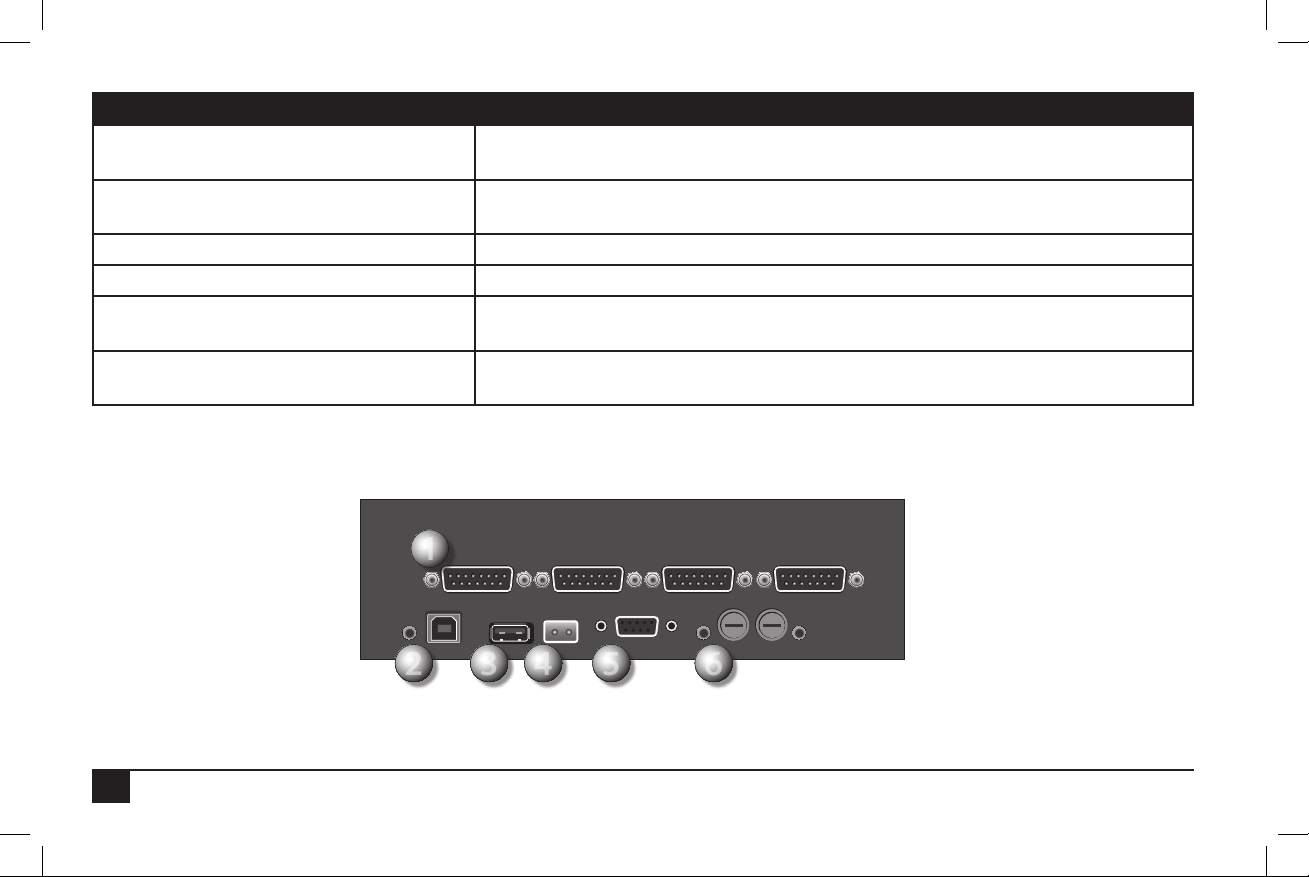
Bottom Ports Purpose
1. Station output ports
(15-pin connectors) (up to four)
2. AC adapter and the red “power on” light LED ashes if a program is running.
3. USB port Allows connecting a thumb drive for “ashing” of the rmware.
4. 2-prong port 24 VAC connection
5. Serial Port (9-pin connector) Both top and bottom serial ports support communications devices, standard o the shelf
6. Two fuse sockets with a red LED light next
to each fuse socket
ese connect to the circuit boards in the Sentinel satellite, controlling up to
12-stations each for a maximum of 48 stations.
e slower the ash, the slower the code is running
serial cables, and are optically isolated.
When the red LED is lit, indicates a blown fuse.
1
6
6
Page 9

II. Programming Overview & Navigation
e Sentinel Controller is programmed by navigating through a Main Menu which includes seven submenus: Manual Watering,
Scheduled Watering, Diagnostics & Alarms, Station Settings, Help, Stop, and Satellite Settings. Each of these submenu options has sys-
tem conguration options. e menu structure is detailed below.
Menu Setting Function
Manual Watering • Manual
• Start/Stop Program
• Turn individual stations ON or OFF for a specic time.
• Start and stop programs.
Scheduled Watering • Start Times
• Prog ET Toggle
• Clear Schedule
• Schedule Length
• Run Days
• Program Clear
• Rain O Days
• Assigned Sched
• Water Window
• Continuous Run
• Repeat Dly (Delay) Time
• Repeats
• Percent Scale
• Slot-Stn-Time
Diagnostics & Alarms • Show Alarms & Warnings
• Clear Sat. Alarms
• Clear Comm. Alarms
• Clear Elec. Alarms
• Clear Flow Alarms
• Show Moisture Data
• Schedule the time for individual stations to activate, by program.
• Program individual programs (up to 16) to use ET data or not.
• Clear schedules of programs, one at a time.
• Set the length of a schedule to run per schedule: six weeks or one year.
• Specify which days per week a schedule should irrigate, by week, by schedule.
• Clear a particular program. Note: ere is no conrmation before clearing.
• Enter “Rain O” days by program, up to 255 days. What is this for?
• Assign schedules to programs or vica-versa.
• Dene “water windows” by program--watering only occurs between specied times.
• Activate a program to run continuously.
• Places a delay period, ranging from 0 to 255 minutes, between program repeats.
• Enables the watering cycle to be repeated from 1 to 250 times per start time.
• Adjust watering time by % of programmed time. Useful for seasonal adjustments.
• For a complete description of this command, see page 23.
• Show the cause of an “Alarm” ashing light.
• Clear any and all Satellite alarms.
• Clear any and all Communication alarms.
• Clearl any and all Electronic alarms.
• Clear any and all Flow alarms.
• A moisture sensor must be installed for this command to work.
7
Page 10

Menu Setting Function
Station Settings • Plant Factor
• Stn Days O
• Maximum Flows
• Expected Flows
• Map Stations
• Station Type
• Precip Rate
• Assign a percentage factor to any zone for the type of plant material.
• Turn o individual stations for a specied number of days (up to 255).
• Set the maximum gallons per minute (GPM) for individual stations.
• Program the expected ow (GPM) for individual stations.
• Each station can be mapped, or associated with hardware other than the Sentinel controller output board. is setting relates to “Station Type” .
• Select the station type per station:
LOCAL, UNIVRSAL, WIRELESS, TORO-2WD, BASELINE, or MC-48E.
• Set the precipitation rate (inches / hr) for each station.
Stop Menu • Full Shutdown
• All Manuals O
• All Autos O
Satellite Settings • Time and Day
• ET
• Language
• Flow Processing
• Flow Factors Meter 2
• Flow Factors Meter 1
• N/O Master
• Station Count
• Unit Code
• Day Change Hour
Help • To be determined
8
• Shut down all stations immediately.
• Turn o all manually running stations.
• Turn o all programmed stations.
• Set the time and day of the satellite.
• Set the maximum and default ET (evapotranspiration) levels.
• Specify the language the satellite uses: English, Spanish, or French.
• Set Flow Processing ON or OFF. Aids in resolving Flow issues.
• See Chapter 2 explanation for this command.
• See Chapter 2 explanation for this command.
• Set the Master Circuit as normally closed or normally open.
• Specify the station count on the satellite, up to 204, in increments of 12.
• See Chapter 2 explanation for this command.
• See Chapter 2 explanation for this command.
Page 11
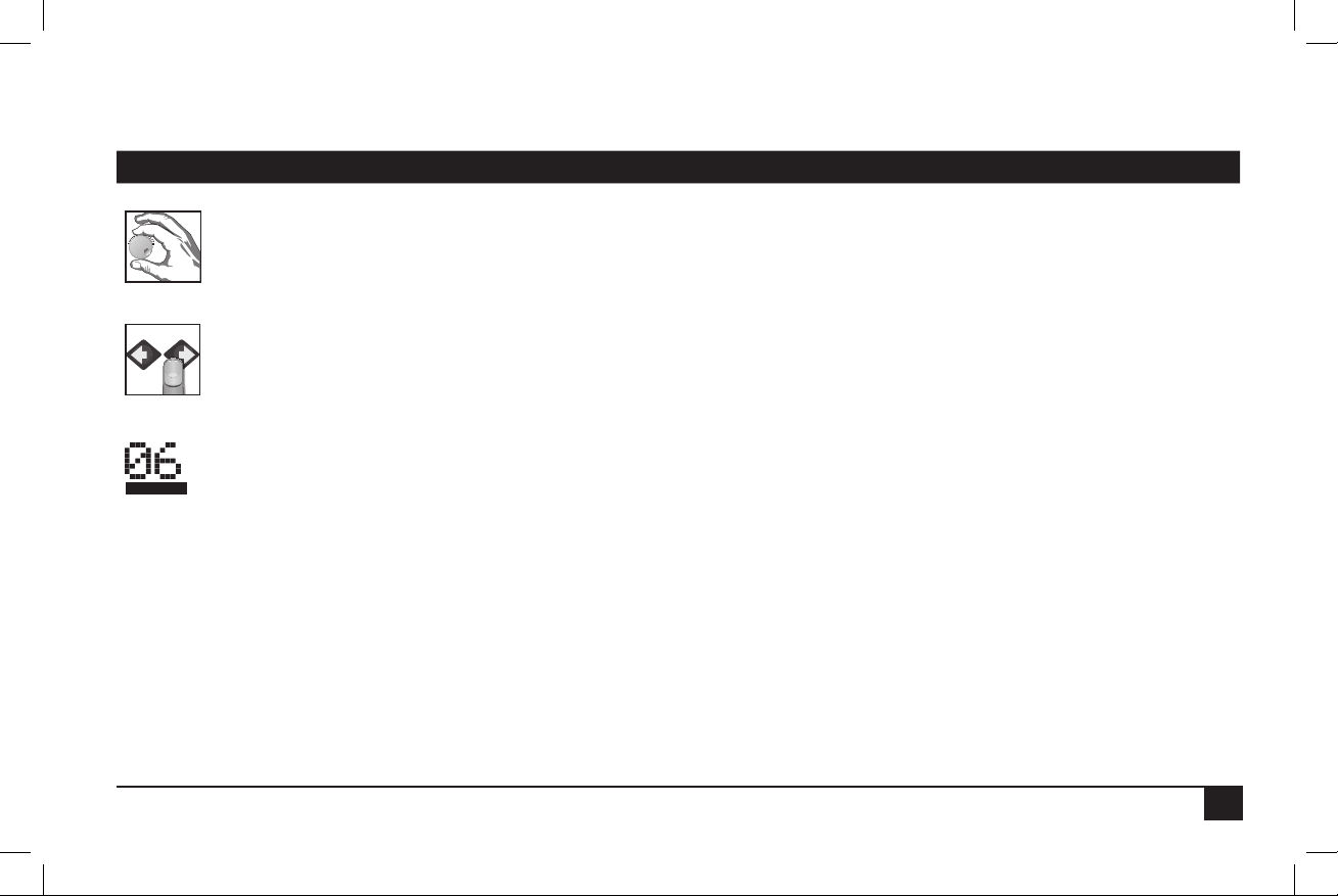
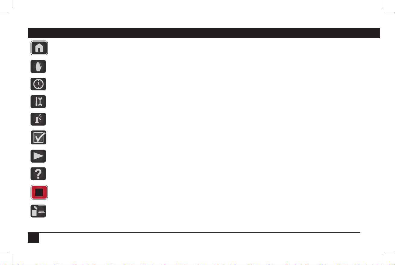
Icons Explained
ere are several icons used throughout the manual to portray certain functions.
Icon Meaning
Turn the Control Knob to change values in the currently highlighted eld.
Press the button / knob pictured under the nger.
A line under characters on the LCD screen indicates a eld that can be adjusted with the Control Knob.
9
Page 12
Chapter 2: Basic Controller Programming
ENTER
- OR -
ENTER
- OR -
is section will provide the information on how to program the basic elements for automatic irrigation to occur. Remember to press ENTER
or the Control Knob after making changes or changes will not be saved.
I. Satellite Settings
• Time and Day
• ET
• Language
• Flow Processing
• Flow Factors Meter 2
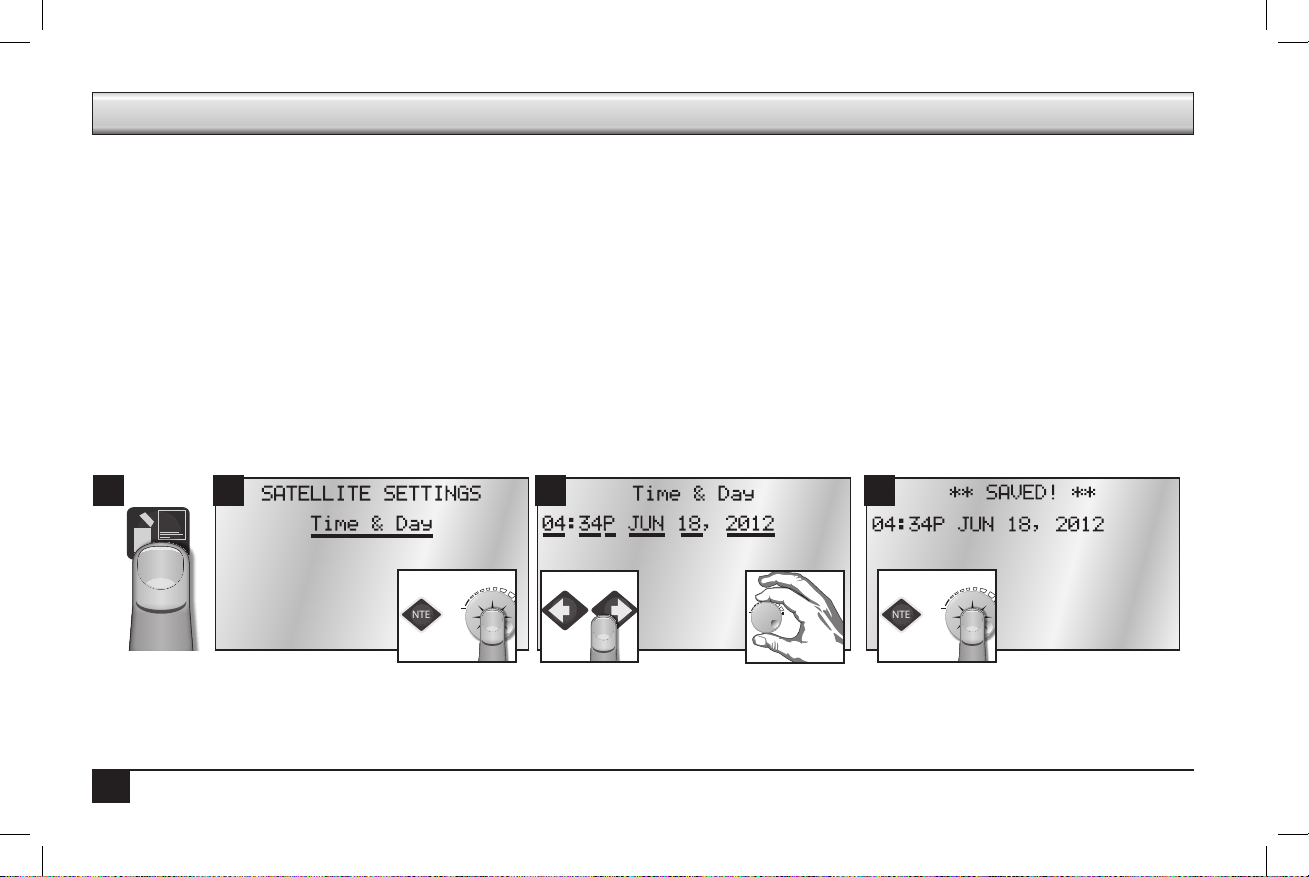
Time & Day (6 Fields to set: Hour, Minute, AM/PM, Month, Date, and Year)
When powering on the Sentinel system for the rst time, it is necessary to set the time and day. Follow the steps below:
2 3 41
• Flow Factors Meter 1
• N/O Master
• Station Count
• Unit Code
• Day Change Hour
10
Page 13
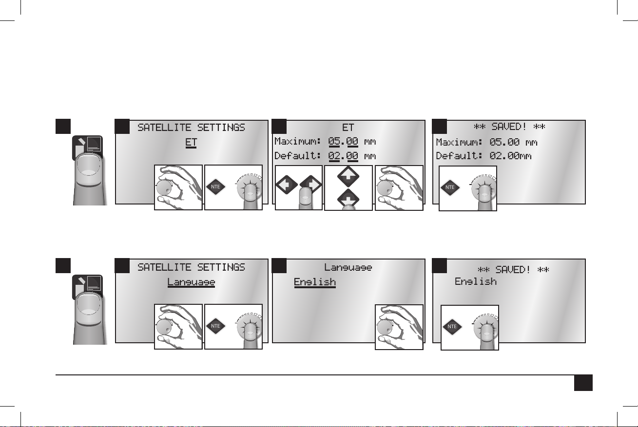
ET (4 Fields to set: Maximum and Default X whole and decimal values)
ENTER
- OR -
ENTER
- OR -
ENTER
- OR -
ENTER
- OR -
Default ET (evapotranspiration) is the minimum ET gure (in millimeters) that is used as the default ET regardless of the weather conditions
or if data is missing from the ET gauge or weather station. ET can vary depending on the time of the season and weather. Generally, daily ET
can be from 0mm to 13mm.
Maximum ET is the maximum ET value that can be accumulated between watering days. is value is the maximum value that a program
will ever replace in a single day. Typically choose a value that is your maximum daily ET multiplied by the number of days between watering.
2 3 41
Language (1 Field to set)
Specify the language the Controller should use. English is the default language.
2 3 41
11
Page 14
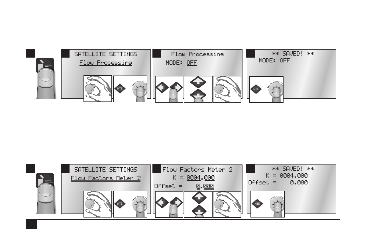
Flow Processing (1 Field to set)
ENTER
- OR -
ENTER
- OR -
ENTER
- OR -
ENTER
- OR -
Turn Flow Processing ON to monitor the ow of water to make sure ow is within limits determined by the irrigation zones running. If the
ow is not within the limits, Sentinel will take user-dened action to identify and label problems.
2 3 41
Note: For the controller to read and react to ow, a ow meter must be connected to the satellite sensor terminals. Do not turn on ow processing if it
is not properly set up.
Flow Factors Meter 2 (4 Fields to set: K and Offset X whole and decimal values)
Flow factors are the K and oset for each meter, used to determine the ow rate in gallons per minute or liters per minute from the raw pulse
rate of the meter. Flow factors are determined by the pipe size and type.
Enter/edit the K factor associated with the ow metering device being used. e K factor and Oset factor may be found in the
Specication sheet for the ow meter.
2 3 41
12
Page 15
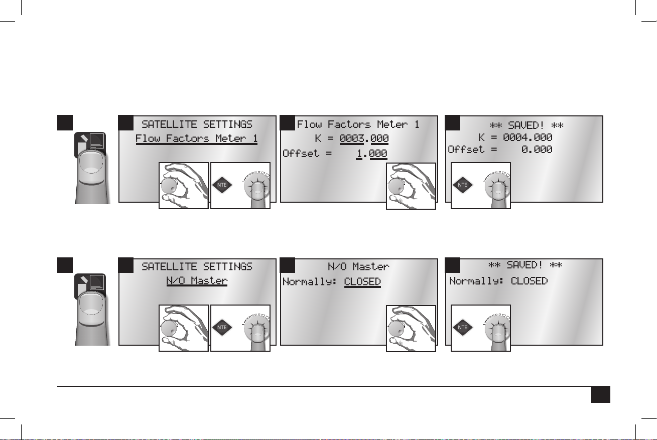
Flow Factors Meter 1 (4 Fields to set: K and Offset X whole and decimal values)
ENTER
- OR -
ENTER
- OR -
ENTER
- OR -
ENTER
- OR -
Flow factors are the K and oset for each meter, used to determine the ow rate in gallons per minute or liters per minute from the raw pulse
rate of the meter. Flow factors are determined by the pipe size and type.
Enter/edit the K factor associated with the ow metering device being used. e K factor may be found in the specication sheet for the ow
meter. e Oset factor may be found in the specication sheet for the ow meter.
2 3 41
N/O Master (1 Field to set)
Congure the master valve/pump start output for either normally OPEN or normally CLOSED operation.
2 3 41
Station Count (1 Field to set)
13
Page 16

Use this menu to inform the controller the number of stations it has. e Sentinel controllers typically have station counts in 12-station incre-
ENTER
- OR -
ENTER
- OR -
ENTER
- OR -
ENTER
- OR -
ments (12, 24, 36, or 48).
2 3 41
Unit Code (1 Field to set)
Every controller must have a three digit code assigned to it. is is known as the controller’s address. It is possible to select any three digit code
from 000 to 999. is is the identier that is used when selecting an individual eld controller with the hand held radio or from the central
controller. If connecting via ethernet (and connecting more than one satellite), set unit codes between 1 and 255. Otherwise it is possible to
set unit codes up to 999.
2 3 41
IMPORTANT: e unit code is required for Central Control operations. Even if most of the satellite programming will be from the central software,
the Unit Code must be set.
14
Page 17

Day Change Hour (1 Field to set)
ENTER
- OR -
ENTER
- OR -
It is possible to set the hour the controller advances to the next day. As an example, the day changes from Monday to Tuesday at midnight. It
is possible to have the controller wait until 8 AM Tuesday before the controller changes the day label to Tuesday. is way, the controller will
have until 8 AM Tuesday to nish all watering cycles from the Monday schedule.
2 3 41
When you choose a day change hour it could lag (be after) or lead (be before) a normal midnight day change. For example, a day change hour
of 11PM indicates the day changes at 11PM, but not what day.
An 11PM LEAD Day Change Hour means the current day changes one hour early.
An 11PM LAG Day Change Hour means the current day changes 23 hours late.
By indicating lead or lag along with the day change hour, Sentinel is able to determine the current irrigation day from the actual day and time.
e day of week displayed on the home screen with the time and month and date, is the irrigation day, not the actual day. ey are only
always the same if the Day Change Hour is set to midnight.
15
Page 18

II. Scheduled Watering
• Start Times
• Prog ET Toggle
• Clear Schedule
• Schedule Length
• Run Days
• Program Clear
• Rain O Days
Schedule refers to the days of the week a program is set to run. Up to 16 unique watering day schedules can be dened in the
Sentinel Controller. Each schedule has a number assignment from 1 to 16. In the controller display, schedules are indicated by “S” and its twodigit schedule number (01, 02,… 16). For example, Schedule 12 is shown as “S12.”
Each schedule can be programmed as either a six week schedule or a 365-day calendar. Toro recommends that all schedule
programming through the faceplate be accomplished using 6-week schedules. Using a 365-day Calendar schedule requires the user to select the
irrigation status for every day of the year. (All days are default OFF.)
A schedule may have any combination of watering days and may be assigned to any of the sixteen programs (covered in the next section, Program Setup). You must assign a schedule to a program to activate it. If using a 6 Week Schedule, the current Schedule Week was set in Time &
Day as part of controller setup (example was set to W1). When the controller reaches the end of a six-week schedule (W6), the program loops
back and starts again with Week 1 (W1).
• Assigned Sched
• Water Window
• Continuous Run
• Repeat Dly (Delay) Time
• Repeats
• Percent Scale
• Slot-Stn-Time
16
Page 19

Start Times (5 Fields to set: Program number, Station number, hour, minute, and AM/PM)
ENTER
- OR -
ENTER
- OR -
ENTER
- OR -
ENTER
- OR -
A Start Time initiates the automatic watering cycle. Each program can be assigned to start up eight times within a 24-hour period.
Note: All start times must occur within the dened Water Window time frame. (See Water Window, below.)
When multiple start times are used, they must be spaced far enough apart to enable the program irrigation cycle to be completed.
e controller oers eight start times per program. If more than eight start times are needed, see Repeats and Continuous Run below. Use
this submenu item to display/edit any one of the eight start times.
2 3 41
Prog ET Toggle (2 Fields to set: Program number, ET ON or OFF)
e controller is capable of running irrigation programs based on ET. When the ET functions are activated, the controller automatically
adjusts program run times according to the ET data. A weather station or ET gauge needs to be connected to the sensor input terminals of the
controller or at the central to provide ET data. Set to ON for any programs you wish to run based on ET values. For time-based watering, set
to OFF. (Default is OFF.)
2 3 41
17
Page 20

Clear Schedule (2 Fields to set: Schedule number, Clear Schedule ON or OFF)
ENTER
- OR -
ENTER
- OR -
ENTER
- OR -
ENTER
- OR -
Clear any one schedule of all programming information.
2 3 41
Schedule Length (2 Fields to set: Schedule number, Schedule length)
Select whether a Schedule (01… 16) is based on a 6-week calendar or a 365-day calendar.
2 3 41
IMPORTANT: Changing the schedule length in either direction will clear the selected schedule.
18
Page 21

Run Days (9 Fields to set: Schedule number, week number, 7 Day-of-week toggles)
ENTER
- OR -
ENTER
- OR -
ENTER
- OR -
ENTER
- OR -
Congure the sixteen independent schedules, dictating what days will be water days or not.
Control Knob to toggle a non-watering day to a watering day. An “X” symbolizes a water day.
2 3 41
Program Clear (2 Fields to set: Program number, Pogram Clear YES or NO)
Set all of the slot/station times within a selected program to zero. is function is helpful when clearing all 16 programs. Manually clearing
station times in all 16 programs would otherwise be very time consuming.
2 3 41
19
Page 22

Rain Off Days (2 Fields to set: Program number, number of “off” days)
ENTER
- OR -
ENTER
- OR -
ENTER
- OR -
ENTER
- OR -
Disable programs for the number of days specied (typically in the event of rain). e Hold LED will be on during Rain O Days. e days
will automatically decrement each day at the Day Change Hour until Rain O Days is zero. e station will then resume normal operation.
2 3 41
Assigned Schedule (2 Fields to set: Schedule number, Schedule length)
Up to 16 unique watering day schedules can be dened in the controller. For identication, each schedule has a number assignment ranging
from 1–16. Each program must be assigned a schedule in order to run.
2 3 41
In Step 3 above, program 3 is being assigned to schedule 2.
20
Page 23

Water Window (7 Fields to set: Program number, “FROM” hour, minute, AM/PM, “TO” hour, minute, AM/PM)
ENTER
- OR -
ENTER
- OR -
ENTER
- OR -
ENTER
- OR -
e Water Window is the period of time in a 24-hour day that automatic watering can occur. Selecting a FROM and TO time denes the
Water Window start time and end time. A program that is running at the end of the Water Window is terminated immediately. Use Water
Windows to set up continuous run start and stops automatically.
2 3 41
Continuous Run (2 Fields to set: Program number, Continuous Run OFF or ON)
Selecting Continuous Run will automatically repeat the program cycle continuously for the dened Water Window duration.
e controller is capable of running any one or combination of programs continuously. To manually start the desired program, use the same
procedure as in Auto Slot/Stn. Use the CLUSTER SELECT and the PROGRAM SELECT keys to select the desired cluster program. Use the
ON and OFF keys to turn continuous run on and o. Press ENTER to save. Use Water Windows below to set up continuous run start and
stops automatically.
2 3 41
21
Page 24

Repeat Delay Time (2 Fields to set: Program number, minute delay)
ENTER
- OR -
ENTER
- OR -
ENTER
- OR -
ENTER
- OR -
Places a delay period, ranging from 0 to 255 minutes, between program repeats. (See Repeats, below.) Use this menu item to display/edit the
repeat delay time for any one of the 16 programs.
2 3 41
Repeats (2 Fields to set: Program number, repeat value)
Enables the watering cycle to be repeated from 1 to 250 times per start time.
2 3 41
22
Page 25

Percent Scale (2 Fields to set: Program number, percent value)
ENTER
- OR -
ENTER
- OR -
Adjusts the run time of stations assigned to the program by percentage ranging from 0 to 255% (100% = no change).
2 3 41
Slot-Station-Time (5 Fields to set: Program number, slot, station, run time duration hour and minute)
One of the most powerful programming features of the Sentinel Controller is the method used to organize and control satellite
station outputs, referred to as “Program Slots”, within each irrigation program. “Program Slots” are organized in a sequential matrix from Slot
1 to Slot 48, for a total of 48 slot positions. From the factory, the Slot and Station numbers are set to be the same; i.e., Station 1 is assigned to
Slot 1 and will run rst. Station 2 will run next in Slot 2, etc.
e program operating sequence runs from Slot 1 to 48. Stations are assigned to a slot and given a run time duration ranging from 0 to 4
Hour and 15 Minutes. Station numbers range from 0 (inactive) to 48. Stations can be assigned to slots in any order and as many times as
desired (that is, one station can appear multiple times in the 48 Slots of one program).
When an irrigation program is running, any slot with 0 (or blank) run time is ignored. A slot with an assigned run time duration ≥1 minute,
but without a station assignment, will create a pause in the watering cycle for the assigned duration.
Sentinel programming allows reconguring the operating order of the stations by enabling any station to be assigned to any slot.
Note: is feature (e Slots in a Program) allows the user to run any station in any order desired and even repeat the desired station within the same
program. Keep in mind that the controller will run the slots sequentially. Stations can be assigned to slots allowing any order of programming.
23
Page 26

Visually, the Slots can be represented in a matrix as follows:
ENTER
- OR -
ENTER
- OR -
To program Slot Station Times:
2 3 41
24
Page 27
Chapter 3: Advanced Programming
ENTER
- OR -
ENTER
- OR -
is section covers Menus and Submenus not covered as part of Basic Programming: Manual Watering, Stop Menu, and Diagnostics and
Alarms.
I. Manual Watering
• Manual • Start / Stop Program
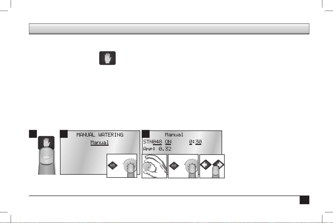
Manual (2 Fields to set: Station number and duration of manual run)
It is possible to manually operate up to six stations at one time. As shown in Step 3, use the Control Knob to select the station to run. en
press ENTER or the Control Knob. e default run time is 30 minutes. It is possible to adjust the run time manually at any time during the
run time.
Activating a station requires power. Exceeding the maximum allowable output current when turning on multiple stations will one, cause the
controller to automatically turn o the station that caused the condition, and two, ag the station so that it will not run again. is is a safety
feature that prevents an over-current condition from exceeding the output capacity of the satellite. If the station is checked and found to be
electrically safe, remove the disable ag through the Over Currents (Alarms) menu item.
2
31
25
Page 28
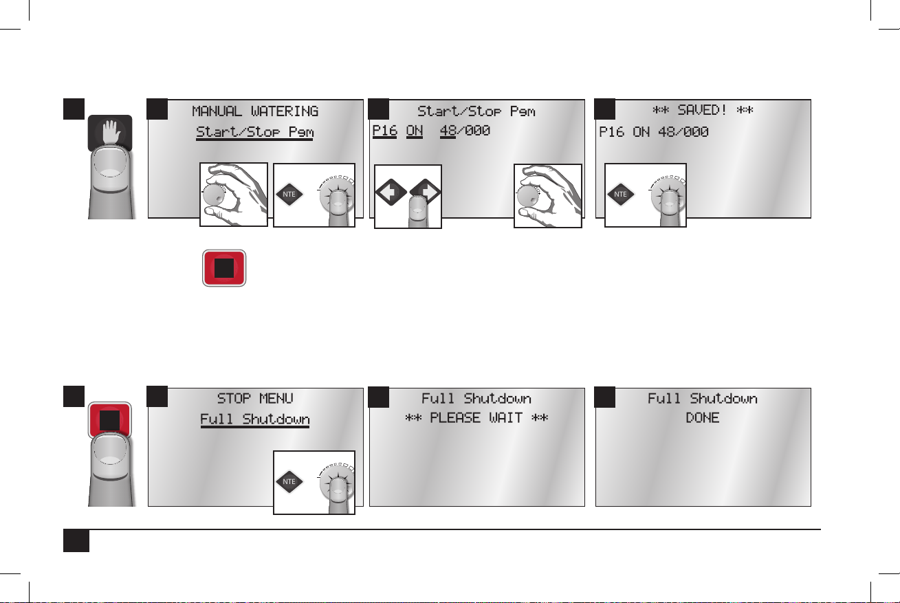
Start / Stop Program (3 Fields to set: Program number, ON or OFF, and station number)
ENTER
- OR -
ENTER
- OR -
ENTER
- OR -
2 3 41
II. Stop Menu
• Full Shutdown
• All Manuals O
Full Shutdown
Shuts down all currently active stations.
2
1
26
• All Autos O
3 4
Page 29

All Manuals Off (Manual Stations Off)
ENTER
- OR -
ENTER
- OR -
Turn o any and all stations that have been turned on manually without having to select each station individually. If more than one manual
station is on, the controller will turn o one station at a time every ve seconds to prevent the possibility of water hammer.
2 31
All Autos Off (Manual / Auto Programs Off)
Turn o any automatic programs (or manually started programs) that may be running.
2 31
4
4
27
Page 30

III. Alarms Menu
ENTER
- OR -
ENTER
- OR -
• Show Alarms & Warnings
• Clear Sat. Alarms
• Clear Elec. Alarms
• Clear Flow Alarms
• Clear Comm. Alarms
Note: e controller is capable of posting alarms when it detects excessive water ow or excessive current.
Show Alarms & Warnings
Show any current alarms on the rst line and the last time and date there was an alarm.
2 3 41
Clear Sat. Alarms
Clear all Satellite alarms on all stations. Normal program operation will then resume.
2 31
4
28
Page 31

Clear Comm. Alarms
ENTER
- OR -
ENTER
- OR -
Clear all communication alarms on all stations. Normal program operation will then resume.
1
2
3
Clear Elec. Alarms
Clear all electrical alarms on all stations. Normal program operation will then resume.
2 3 41
4
29
Page 32

Clear Flow Alarms
ENTER
- OR -
ENTER
- OR -
Clear all ow alarms on all stations. Normal program operation will then resume.
2 31
4
Show Moisture Data
When equipped with an optional Turf Guard receiver module, incoming moisture packets are displayed on screen and recorded to a log le.
When connected to the Internet via the Ethernet connection, moisture data is sent to the Turf Guard servers.
2 31
30
Page 33
IV. Station Settings
ENTER
- OR -
ENTER
- OR -
ENTER
- OR -
ENTER
- OR -
• Plant Factor
• Stn Days O
• Maximum Flows
• Map Stations
• Station Type
• Precip Rate
• Expected Flows
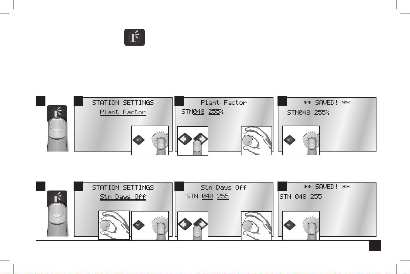
Plant Factor (2 Fields to set: Station number and percentage)
Assign a percentage factor (0 - 255%) to any zone for the type of plant material that the zone is irrigating. For instance, it is possible to assign
a bluegrass turf zone a factor of 100% and a ground cover zone that needs less water a 50% factor.
2 3 41
Station Days Off (2 Fields to set: Station number and number of days off)
Disable individual stations for the number of days specied. e Hold LED will be on during Station Days O. e days will automatically
decrement each day at the Day Change Hour until Days O is zero. e station will then resume normal operation.
2 3 41
31
Page 34

Maximum Flows (2 Fields to set: Station number and max flow in GPM)
ENTER
- OR -
ENTER
- OR -
ENTER
- OR -
ENTER
- OR -
Specify/enter the maximum ow values in gallons per minute for each individual station.
2 3 41
Expected Flows (2 Fields to set: Station number and expected flow in GPM)
Enter/edit the Expected Flow values (in gallons per minute) for individual stations. Expected ow values will be displayed even if there is no
ow meter to collect and read actual ow values.
2 3 41
32
Page 35

Map Stations (4 Fields to set: Station number, station type codes and parameters)
ENTER
- OR -
ENTER
- OR -
Each station can be mapped to, or associated with, hardware other than the Sentinel controller output board. is setting relates to
“Station Type” as set below.
e 2.42 Firmware Map Stations menu item is in the form of: SS -> AAA/BBB:CC (See programming chart below.)
2 3 41
Each station can be mapped to, or associated with, other hardware by way of the 8 numbers to the right of the arrow. e eld labeled SS is
the Sentinel station to be mapped (01-48). e rest of the elds depend on the station type programming.
Station Type Programming
LOCAL No mapping necessary, any values entered are ignored.
UNIVERSAL Set AAA = 000
Set BBB = unit code of map to universal eld unit
Set CC = map to universal output number
TORO-2WD (Toro TwoWire):
WIRELESS and
WIRELESS-LR
Set AAA/BBB = 0xx/xxx where x is the 5 digit decoder address
Set CC = decoder output number 01-04
Set AAA = board group
Set BBB = 00x where x is the switch position (board number)
Set CC = output number (1 - 12).
33
Page 36

BASELINE Set AAA/BBB:CC = 000/001:xx where xx is decoder address.
ENTER
- OR -
ENTER
- OR -
We set BBB = 001 (address of Baseline gateway connected to Sentinel serial port). CC decoder address
maps to a specic physical decoder (serial number) in the Baseline Setup Software.
Station Type (2 Fields to set: Station number and station type)
e following station types are available:
UNIVRSAL – Use this option to turn on outputs locally and on a universal map to (when mapped). (is is the default option.)
LOCAL – Use this option to turn outputs on locally (out the front of the satellite).
TMC-424 – Not currently utilized. Toro TMC-424 Controller.
BL-FL/PR – Not currently utilized. Baseline Flow & Pressure.
BL-SENS2 – Not currently utilized. Baseline Sensor.
BL-SENS2 – Not currently utilized. Baseline Sensor.
BASELINE – Use this option to turn output on locally and on Baseline two-wire system.
WIRELESS – Choose this option to run outputs on a wireless output board.
TORO-2WD - Use this option to turn output on locally and on Toro two-wire system.
WIRELESS-LR (long range) - Allows operation of wireless output boards via a long range radio connected to one of the Sentinel
satellite’s external serial ports.
2 3 41
34
Page 37

Precipitation Rate (2 Fields to set: Station number and precipitation rate)
ENTER
- OR -
ENTER
- OR -
is is the amount of water a zone applies in inches per hour. For example, a zone of xed spray heads may apply the water at the rate of 2”
per hour while a rotary sprinkler zone may apply water at the rate of 0.50” per hour.
It is possible to determine a zone’s application rate by multiplying its gallons per minute by 96.3 and dividing that gure by the square feet
covered by the zone.
2 3 41
35
Page 38

Frequently Asked Questions
1. How do I update the rmware and language programming?
For complete instructions on how to update the rmware programming and langauges for the Sentinel system, go to the
Sentinel support website at:
http://www.toro.com/en-us/professional-contractor/irrigation/central-control-systems/Pages/Model.aspx?pid=Sentinel.
2. I have cleared all alarms, but the alarm indicator is still blinking.
ere are three possibilities: One, there may be an external alarm; the date and time might still have to be set; or three, so many
stations are running a volumetric shutdown has been triggered.
3. What happened to 2Wire/Irritrol Mode?
2Wire/Irritrol Mode has been removed from the keypad menu and is no longer being used. We do not send anything on any
port that has not been requested, so it is no longer possible to connect a 2-wire gateway. e only commands sent to that port
were for the 2-wire gateway. As a result, this ag is no longer needed.
4. Why does the time/day screen fail to synchronize?
Unlike old Sentinel systems, the new satellite stores the Schedule Reference Date. is requires the central to send the SRD. An
update to the central to send the SRD will be available soon. To avoid the issue for now, set the SRD in the central software to
Dec 7, 2009.
Note: Once the central sends the SRD, be sure to choose a SRD in the central software that is in the past.
36
Page 39

Troubleshooting Guide
Problem Possible Cause Solution
No display. AC power not reaching controller.
Blown fuse.
14-pin ribbon-cable connector is not fully
connected.
Check and x AC power supply to controller.
Check fuses. Determine why blown and replace if necessary.
Check ribbon cable connections on bottom of unit.
Controller does not irrigate as
scheduled.
Water does not turn ON. Programming error.
Water does not turn OFF. Programming error--too many start times.
Rain sensor does not shut down
system.
Programming error.
Time and date error.
Sensor is shutting down system.
Station Alarms set.
Faulty valve wire connections.
Bad / defective solenoid or valve.
Flow control or water shut o.
Bad / defective solenoid.
Valve blockage.
Programming error.
Faulty sensor or faulty sensor connection.
Verify programming information with Central or In Display.
Very time and date.
Remove sensor, clear, and retest.
Look for alarms. Correct issue if set, and clear alarms.
Verify programming information with Central or In Display.
Look for alarms. Correct issue if set, and clear alarms.
Test for 24 VAC from Station Post to Common or Ground with
Manual switch on.
Check ow control valve and water supply line.
Verify programming information with Central or In Display.
Test for 24 VAC from Station Post to Common or Ground with
Controller running and/or Manual switch on.
Check for cross connections between stations.
Shut o power at controller. If station stays on, isolate and troubleshoot valve.
Verify programming information with Central or In Display.
Verify and reset.
37
Page 40

Toro Warranty and Dedication to Quality
The Toro Company and its affiliate, Toro Warranty Company, pursuant to an agreement between them, jointly warrants, to the owner, against defects in
material and workmanship for a period of five years from the date of purchase. Neither The Toro Company nor Toro Warranty Company is liable for failure
of products not manufactured by them even though such products may be sold or used in conjunction with Toro products. During such warranty period,
we will repair or replace, at our option, any part found to be defective. Return the defective part to the place of purchase.Our liability is limited solely to
the replacement or repair of defective parts. There are no other express warranties. This warranty does not apply where equipment is used, or installation is
performed, in any manner contrary to Toro’s specifications and instructions, nor where equipment is altered or modified. Neither The Toro Company nor
Toro Warranty Company is liable for indirect, incidental or consequential damages in connection with the use of equipment, including but not limited to:
vegetation loss, the cost of substitute equipment or services required during periods of malfunction or resulting non-use, property damage or personal injury
resulting from installer’s negligence.
Some states do not allow the exclusion or limitation of incidental or consequential damages, so the above limitation or exclusion may not apply to you.
All implied warranties, including those of merchantability and fitness for use, are limited to the duration of this express warranty. Some states do not allow
limitations of how long an implied warranty lasts, so the above limitation may not apply to you.This warranty gives you specific legal rights and you may
have other rights which vary from state to state.
Toro is committed to developing and producing the highest quality, best performing, most dependable products on the market. Because your satisfaction is
our first priority, we have provided the Toro Helpline to assist you with any questions or problems that may arise. If for some reason you are not satisfied
with your purchase or have questions, please contact your local authorized Toro dealer or e-mail irrigation.support@toro.com.
FCC Statement
is equipment has been tested and found to comply with the limits for a Class A digital device, pursuant to part 15 of the FCC Rules. ese limits are designed to provide reasonable protection against harmful interference in a residential installation. is equipment generates, uses and can radiate radio frequency energy and, if not installed and used in accordance with the instructions, may cause harmful interference to radio communications. However, there is no
guarantee that interference will not occur in a particular installation. If this equipment does cause harmful interference to radio or television reception, which
can be determined by turning the equipment o and on, the user is encouraged to try to correct the interference by one or more of the following measures:
•
Reorient or relocate the receiving antenna.
•
Increase the separation between the equipment and receiver.
•
Connect the equipment into an outlet on a circuit dierent from that to which the receiver is connected.
•
Consult the dealer or an experienced radio/TV technician for help.
If necessary, the user should consult the dealer or an experienced radio/television technician for additional suggestions. e user may nd the following booklet prepared by the Federal Communications Commission helpful: “How to Identify and Resolve Radio-TV Interference Problems.” is booklet is available
from the U.S. Government Printing Oce, Washington, D.C., Stock No. 004-000-00345-4 (price – $2.00 postpaid).
38
Page 41

Notes
e Toro Company
5825 Jasmine Street
Riverside, CA 92504
© 2013 e Toro Company, Irrigation Division • www.toro.com • 1-877-345-8676 Form Number 373-0759 Rev. B
39
 Loading...