

Page 1

Model #UTV700AAC000EP - Serial #4UF16MPV9GT309933 &
Activate/charge/install battery
Form Number 3406-715 Rev. A
Effective May, 2016
Up
PRE-DELIVERY SETUP INSTRUCTIONS
CHECKLIST
Check engine/transmission oil
Check tire inflation pressure
Check wheel lug nut torque
Install left-side foot restraint
Install ROPS/seat belts/side restraints
Check cooling system — level and hoses
Install steering wheel
Check/adjust front wheel alignment
Check hydraulic brake fluid level — pedal firmness
Burnish the brake pads
Check throttle cable adjustment
NOTE: Read these instructions thoroughly before
starting the Pre-Delivery Setup.
Even though the vehicle has been set up (with some
minor exceptions) and inspected at the factory, it is
mandatory that EVERY vehicle be properly inspected
and serviced at the dealership prior to being released to
the customer. Experience has shown that dealerships
that properly prepare each vehicle have fewer warranty
problems and more satisfied customers.
RECOMMENDED TOOLS
The following tools will assist the technician during the
set-up process:
• Drill w/Torx Bits
• Impact Wrench
• Metric Socket Set
• Torque Wrench
BATTERY
NOTE: Refer to all warnings and cautions provided with the battery or battery charger.
This ROV is shipped with a sealed battery. The battery
requires an initial charge after activation as well as periodic
maintenance-charging during periods of non-use or storage.
Activating Battery
Always activate and maintain the battery in accordance
with the following instructions to ensure maximum service life and performance from the battery.
Check gear case lubricant
Check shift lever for proper operation
Check headlight aim
Check gasoline level
Start engine and check electrical switches and lights
Test drive
Check decals/clean vehicle
Explain Operator’s Manual, Limited Warranty, and
legal obligations to the customer
Complete Owner Registration form with the customer
on the date of the sale
Each sealed battery comes with an electrolyte container and
proper amount for each specific battery type. DO NOT add
additional electrolyte to any sealed battery. Sealed battery
electrolyte has a higher concentration of sulfuric acid.
1. Carefully remove and save the sealing strip from the
battery electrolyte container. This will be used to seal
the battery later.
2. Remove and discard the foil sealing strip covering
the fill holes from the battery.
3. Place electrolyte container with the foil-sealed top of
the cells facing down into the fill ports of the battery.
4. Hold the container level in the fill ports of the battery. Push down to break the seals. Air bubbles will
appear as the ports fill. Do not tilt the electrolyte container. Do not remove the container from the battery
until all cells are completely empty.
5. Let the battery stand for 120 minutes (2 Hr) prior to
charging. This will allow the electrolyte to permeate
into the plates for optimum performance.
6. Fully insert the sealing strip over the fill holes by
hand. DO NOT use a hammer.
7. Charge the battery completely before installation.
Charging New Battery
NOTE: Batteries filled with electrolyte are only at
80% of their capacity.
Batteries can be charged two ways - Standard Charge and
Fast Charge. Standard charging is the only recommended
way to charge a battery. It gives the battery optimal performance and battery life.
1. Be sure the charger is unplugged from the 110-volt
electrical outlet.
1
Page 2
2. Connect the red terminal lead from the charger to the
positive terminal of the battery; then connect the
black terminal lead of the charger to the negative terminal of the battery.
3. Plug the charger into a 110-volt electrical outlet.
4. Charge the battery for a minimum of five full hours
at a rate of 10% of the battery amp-hour rating for
optimal battery performance and battery life (ex: 30
AH battery should be charged at 3.0 amps).
NOTE: If the battery becomes hot to the touch,
stop charging. Resume after it has cooled.
5. Once the battery has reached full charge (typically
13.5 volts), unplug the charger from the 110-volt
electrical outlet and disconnect the charging leads.
6. Allow the battery to sit for 2 hours before installing
in the vehicle.
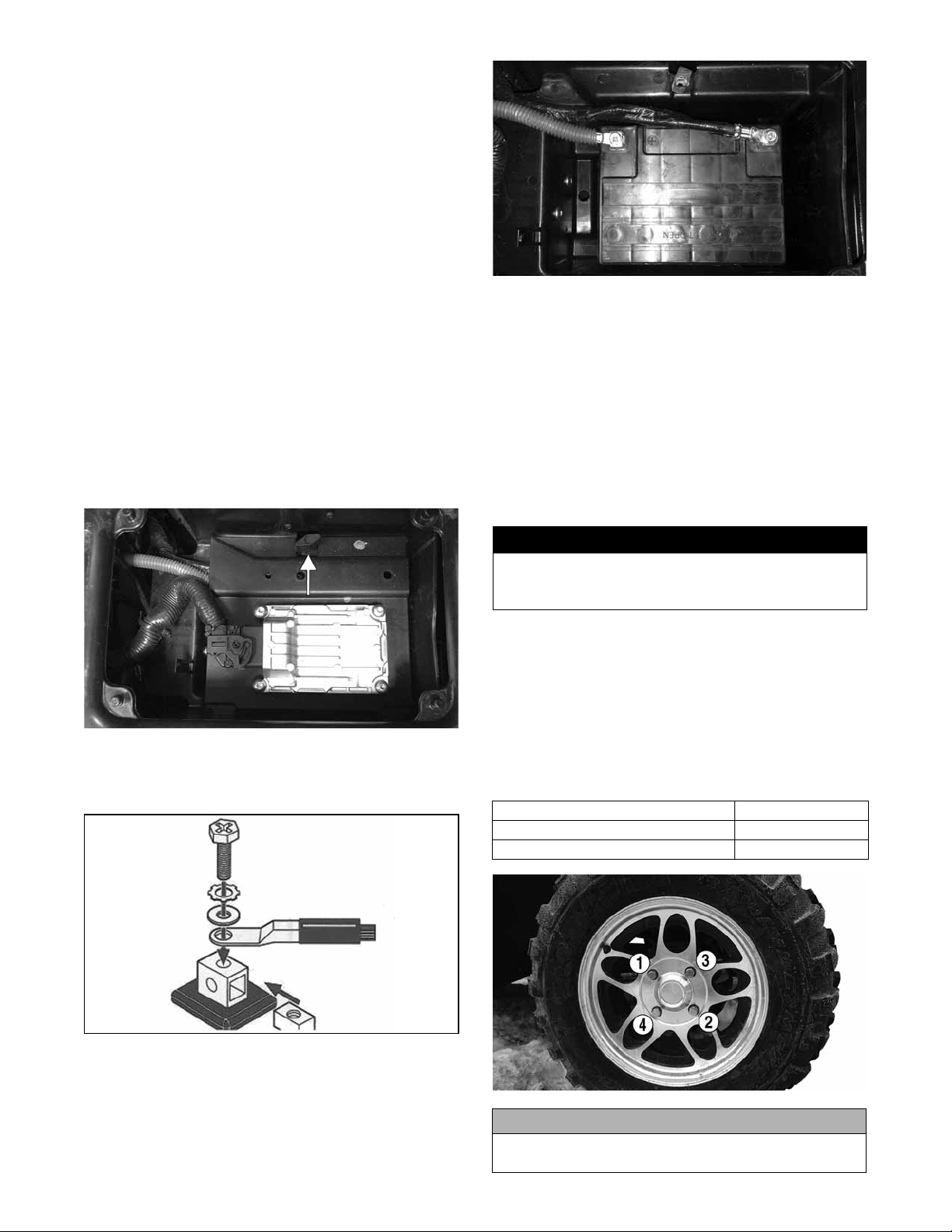
Installing Battery
NOTE: The battery box is under the seat on the
operator’s side. To access the box, remove the
seat and pry off the battery compartment cover;
then remove the thumb screw securing the battery
box cover and lift the cover to access the battery.
PR942
NOTE: Loss of battery charge may be caused by
ambient temperature, ignition OFF current draw,
corroded terminals, self-discharge, or other factors. Maintenance charging is required to keep the
battery at a “fully-charged” state.
TIRES
This vehicle is equipped with low-pressure tubeless
tires. Do not under any circumstances substitute tires of
a different type or size.
TIRE INFLATION PRESSURE
! WARNING
Operating this vehicle with improper or uneven tire
inflation pressure is hazardous. Always maintain
proper tire inflation pressure.
Front and rear tire inflation pressure should be 138 kPa
(20.0 psi).
A low-pressure gauge is provided in the tool kit to measure the air pressure in the tires. Check the air pressure
in all tires before use of the vehicle.
PR943A
1. Route the battery cables into the battery compartment.
2. Install the battery; then connect the battery cables
(positive cable first) as shown. Tighten securely.
TC019
NOTE: When installing the battery into a vehicle,
coat the battery terminals with a light coat of
grease to minimize battery terminal corrosion and
then cover with the terminal boot if provided.
2
WHEEL LUG NUTS
Using a crisscross pattern, tighten the wheel nuts in 27 Nm (20 ft-lb) increments to the final torque shown below.
Steel Wheel 54 N-m (40 ft-lb)
Aluminum Wheel (Black Nuts) 80 N-m (60 ft-lb)
Aluminum Wheel (Chrome Nuts) 108 N-m (80 ft-lb)
PR941A
CAUTION
Using an impact wrench could result in incorrect
torque which could damage the wheel or hub studs.
Page 3
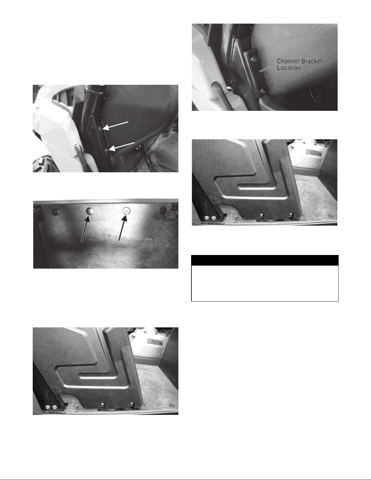
INSTALLING LEFT-SIDE FOOT RESTRAINT
1. Remove the left-side foot restraint from the package
containing the side restraints.
2. Remove two sheet metal screws from the dashboard
attachment location and the second and third floor
retainer screws.
PR751A
PR800A
6. Tighten the cap screws securing the restraint to the
angle bracket securely.
PR752A
3. Remove the angle bracket from the foot restraint
(retain the screws) and attach to the floor using the
existing screws from the floor. Tighten securely.
4. Install the foot restraint and attach to the angle
bracket with the existing two cap screws. Do not
tighten at this time.
PR827
INSTALLING ROPS/SEAT BELTS/ SIDE RESTRAINTS
! WARNING
The ROPS must be installed prior to operating the
vehicle or delivery to a customer. Safety devices such
as taillight/brakelight, seat belts, and the passenger
hand holds are incorporated in the assembly. The
ROPS is part of the vehicle structure.
NOTE: The screws securing the front and rear
tubes during delivery will be used to secure the
ROPS tubes. There are nuts that secure the back
side of the ROPS tubes for shipping; these nuts
should be removed and discarded.
1. Loosen the Allen Head Screws securing the front
and rear ROPS tubes; then tip the front and rear
ROPS tubes from horizontal to vertical.
PR827
5. Secure the restraint and the dashboard with the
channel bracket (from the hardware pack) and two
sheet metal screws. Do not over-tighten.
3
Page 4
UTV-068
UTV-148
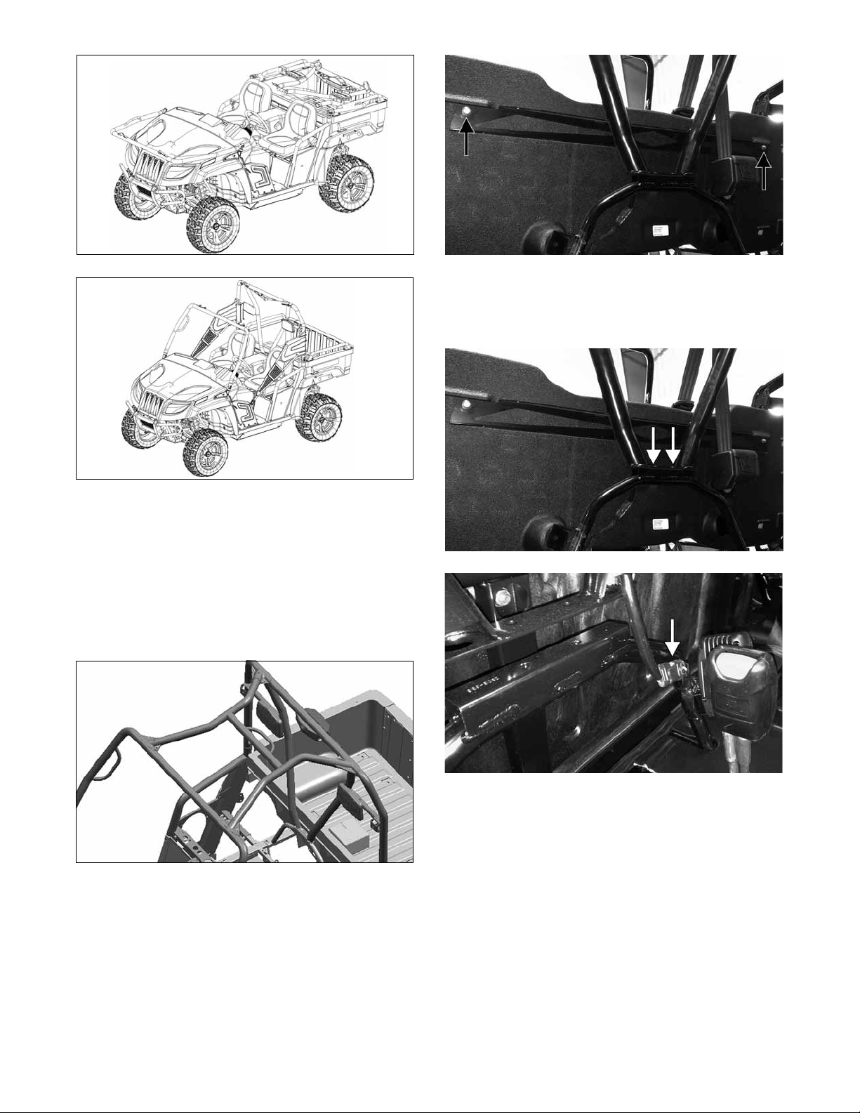
2. Raise the cargo box; then while holding the rear
ROPS, remove the screws securing the ROPS.
Loosely secure the ROPS in the correct position
using Allen Head Screws and new Nyloc Nuts. Do
not tighten at this time. Repeat for the front ROPS.
3. Place the Top X-brace into position between the
front and rear tubes and secure with eight Cap
Screws (installed from the top) and eight Zinc
Nyloc Nuts. Tighten to 47 N-m (35 ft-lb).
TC022A
5. Secure the bottom (middle) of the rear canopy tube
to the center support using two M6 Torx Screws.
Tighten to 11 N-m (8 ft-lb). Connect the brakelight/
taillight harness to the main harness.
TC022B
UTV-070
4. Secure the seat back to the rear ROPS tube with the
two cap screws. Tighten to 11 N-m (8 ft-lb).
4
TC030A
6. Tighten the front and rear tubes (from step 2) to 47
N-m (35 ft-lb). Ensure the flats of the nuts engage
the recesses of the ROPS tubes when tightened.
Page 5

TC027
TC029
7. Install the seat belts (cap screws installed from the
front) into the appropriate mounting tabs along the
headrest support tube on the rear ROPS. Tighten to
47 N-m (35 ft-lb).
8. Place Right-Side Occupant Side Restraint onto the
passenger-side tube and secure using four Cap
Screws. Tighten to 13.5 N-m (10 ft-lb).
PR834A
11. Loop the rear anchor strap around the ROPS mounting tube and secure with the buckle. Tighten so
strap rests as shown.
PR831A
12. Repeat steps 9-11 for opposite side.
13. Secure both side restraints to the kick panels using
the buckle.
PR835A
9. Secure the outer side restraint using two Cap
Screws making sure to keep the straps properly
positioned.
10. Route the lower side restraint straps inside the side
tube; then secure to the frame using two Shoulder
Screws and Flange Nuts. Tighten to 13.5 N-m (10
ft-lb).
PR833
CHECKING COOLING SYSTEM
Remove the filler cap and check coolant level. Coolant
level should be at the bottom of the standpipe in the
radiator neck. If coolant is required, add to bring coolant
to the specified level and install the cap.
NOTE: If coolant is required, mix coolant for a
temperature of -36°C (-34°F). Follow mixing recommendations of the manufacturer.
CAUTION
It is extremely important that the cooling system is
properly filled. If the system isn’t properly filled,
engine damage will occur.
5
Page 6

INSTALLING STEERING WHEEL
NOTE: The vehicle should be on level ground
with the front wheels oriented straight forward and
rearward.
1. Remove the nut and the steering wheel from the
steering shaft.
2. Install and align the steering wheel and loosely
secure with the nut.
NOTE: This model has a castle nut/lock clip and
drilled steering shaft. The lock clip will be in the
steering wheel hardware package.
3. Verify that the steering wheel is oriented correctly
and the front wheels are aligned straight forward;
then apply one drop of red Loctite #271 to the
threads and tighten the nut to 34 N-m (25 ft-lb).
4. Install the lock clip through the steering shaft and
nut. Install the steering wheel cover.
PR087A
To adjust the wheel alignment, use the following procedure:
1. Center the steering wheel; then using an open-end
wrench to hold the tie rod ends (A), loosen the
right-side and left-side jam nuts (B).
HDX131A
NOTE: If the hole in the steering shaft does not
align with the slots in the castle nut, tighten the nut
slightly until the next slot aligns with the hole.
NOTE: Adding a small amount of grease to the
cover bores may aid in installing the cover.
CHECKING/ADJUSTING FRONT WHEEL ALIGNMENT
NOTE: All measurements and adjustments must
be made with the vehicle unloaded.
Mark the center-line of the front tires at the front and
rear of the tire; then using a tape measure, measure and
record the distance between the marks at the front and
rear. The front measurement should be 3-6 mm (1/8-1/4
in.) greater than the rear measurement (toe-out).
HDX098B
PR792A
CAUTION
Always use a wrench to hold the tie rod ends when
loosening or tightening the jam nuts or damage to
the boots could occur.
2. Turn the left-side and right-side tie rods (C) in equal
increments to achieve the proper toe-out; then
tighten the jam nuts securely.
3. Check for free steering operation (full-left/full-right).
CHECKING HYDRAULIC BRAKE SYSTEM
The hydraulic brake system has been filled and bled at the
factory.
6
Page 7

1. With the hydraulic brake reservoir in a level position, check the fluid level. It must be visible at the
MAX line.
TC021A
2. Press the brake pedal several times to check for
firmness. If the pedal is not firm, the brake system
must be bled.
3. To bleed the brake system, use the following procedure:
A. Remove the cover and fill the reservoir with
DOT 4 approved brake fluid.
B. Install and secure the cover; then slowly press
the brake pedal several times.
C. Install one end of a clear hose onto the REAR
bleed screw and direct the other end into a container; then while holding slight pressure on the
brake pedal, open the bleed screw and watch for
air bubbles. Close the bleed screw before
releasing the brake pedal. Repeat this procedure
until no air bubbles are present.
4. Carefully check the entire hydraulic brake system
that all hose connections are tight, the bleed screws
are tight, and no leakage is present.
5. Make sure to burnish the brake pads during the test ride.
CHECKING THROTTLE CABLE ADJUSTMENT
1. Check cable free-play by grasping the cable at the
top of the accelerator pedal and lightly pulling rearward to remove slack. Free-play should be 1-2 mm
(0.040-0.080 in.).
PR708A
2. Depress the accelerator pedal completely and pull
rearward on the cable end. There should not be any
free-play and the tension sleeve should not be compressed.
PR080A
NOTE: During the bleeding procedure, watch the
reservoir very closely to make sure there is always
a sufficient amount of brake fluid. If the fluid level
gets low in the reservoir, refill the reservoir before
the bleeding procedure is continued.
D. Repeat step C until the brake pedal is firm.
E. At this point, perform step B, C, and D on the
FRONT RIGHT bleed screw; then move to the
FRONT LEFT bleed screws and follow the same
procedure.
PR709A
3. To adjust the throttle cable, remove the throttle arm
cover on the throttle body; then loosen the two
adjuster nuts and adjust for proper free-play.
TC020A
4. Tighten the jam nut securely.
7
Page 8

CHECKING ENGINE/ TRANSMISSION OIL LEVEL
NOTE: Inspect the area around the drain plug
(under the vehicle) and oil filter (front of the
engine) for leaks.
PR078A
NOTE: To access the oil filter, remove the seat.
Remove the screws securing the seat back and
remove the seat back; then remove the screws
securing the seat base and remove the seat base.
NOTE: The vehicle should be on level ground
when checking the engine oil level.
1. Raise the cargo box; then unscrew the oil level stick
and wipe it with a clean cloth.
GZ461A
CAUTION
Do not over-fill the engine with oil. Always make sure
the oil level is within the operating range.
Recommended Engine/ Transmission Oil
CAUTION
Any oil used in place of the recommended oil could
cause serious engine damage. Do not use oils which
contain graphite or molybdenum additives. These
oils can adversely affect clutch operation. Also, not
recommended are racing, vegetable, non-detergent,
and castor-based oils.
The recommended oil to use is Toro 0W-40 All Weather
synthetic engine oil, which has been specifically formulated for use in this engine. Although Toro 0W-40 All
Weather synthetic engine oil is the only oil recom-
mended for use in this engine, use of any API certified
SM All-Weather synthetic 0W-40 oil is acceptable.
PR053B
2. Install the oil level stick into the engine case threading the stick in for checking purposes.
3. Remove the oil level stick; the engine oil level
should be within the operating range but not above
the FULL mark.
8
OILCHARTJ
CHECKING GEAR CASE LUBRICANT LEVELS
1. Remove the front differential level plug; lubricant should
be visible at the plug threads. If low, add SAE approved
80W -90 hypoid lubricant to the fill plug as necessary.
Install the plug and tighten to 22 N-m (16 ft-lb).
CAUTION
Any lubricant used in place of the recommended lubricant could cause serious front differential damage.
Page 9

HDX083A
2. Remove the rear drive level plug; lubricant should be
visible at the plug threads. If low, add SAE approved
80W -90 hypoid lubricant to the fill plug as necessary.
Install the plug and tighten to 22 N-m (16 ft-lb).
CAUTION
Any lubricant used in place of the recommended
lubricant could cause serious rear drive damage.
2. Measure the distance from the floor to the midpoint of each headlight.
3. Using the measurements obtained in step 2, make
horizontal marks on the aiming surface.
4. Make vertical marks which intersect the horizontal
marks on the aiming surface directly in front of the
headlights.
5. Switch on the lights. Make sure the HIGH beam is
on. DO NOT USE LOW BEAM.
6. Observe each headlight beam aim. Proper aim is
when the HIGH beam is centered on the vertical
mark 5 cm (2 in.) below the horizontal mark on the
aiming surface.
7. Turn the adjuster nut clockwise to raise the beam
and counterclockwise to lower the beam.
HDX084A
CHECKING/ADJUSTING HEADLIGHT AIM
The headlights can be adjusted vertically. The center of
the HIGH beam light zone is to be used for aiming.
1. Position the vehicle on a level floor so the headlights are approximately 6.1 m (20 ft) from an aiming surface (wall or similar aiming surface).
TC004A
RECOMMENDED GASOLINE
The recommended gasoline to use is 87 minimum octane
regular unleaded. In many areas, oxygenates are added to
the gasoline. Oxygenated gasolines containing up to 10%
ethanol or 5% methane are acceptable gasolines.
When using ethanol blended gasoline, it is not necessary
to add a gasoline antifreeze since ethanol will prevent
the accumulation of moisture in the system.
CAUTION
Do not use white gas. Only Toro approved gasoline
and/or additives should be used.
TEST DRIVING
1. Check all mechanical functions.
2. Burnish the brake pads (see Burnishing Brake Pads).
3. Confirm all cables and wiring harnesses are connected and routed correctly.
4. Confirm all lights work correctly: headlights (HILO), taillight/brakelight, gauge, dash.
5. Confirm cooling fan operates normally.
6. After the test drive, check the brake systems.
0740-647
NOTE: There should be an average operating load
on the vehicle when adjusting the headlight aim.
7. Inspect the owner’s packet to ensure it is complete
(Operator’s Manual, spanner wrench).
8. Visually inspect the entire vehicle for any loose fasteners. Tighten as required to the appropriate specifications.
9
Page 10

9. Confirm final “check-off” of items on the Checklist.
BURNISHING BRAKE PADS
Brake pads must be burnished to achieve full braking
effectiveness. Braking distance will be extended until
brake pads are properly burnished.
! WARNING
Do not attempt sudden stops or put yourself into a
situation where a sudden stop will be required until
the brake pads are properly burnished.
1. Choose an area sufficiently large to safely accelerate to 50 km/h (30 mph) and to brake to a stop.
2. Accelerate to 50 km/h (30 mph); then press brake
pedal to decelerate to 0-8 km/h (0-5 mph).
3. Repeat procedure twenty times.
! WARNING
Using the Operator’s Manual as a guide, instruct the
customer on the proper use, care, burnishing procedure (when brake pads are new), and maintenance of
the hydraulic brake system.
TRANSPORTING
CAUTION
If using additional hold-down straps in any other
areas, care must be taken not to damage the vehicle.
! WARNING
Use extreme caution when operating a machine on a
ramp.
Ensure that the ROPS will clear the top of an
enclosed trailer.
Use only a full-width ramp; do not use individual
ramps for each side of the machine.
Do not exceed a 15-degree angle between the ramp and
the ground or between the ramp and the trailer or truck.
Ensure the length of ramp is at least four times (4X)
as long as the height of the trailer or truck bed to the
ground. This will ensure that ramp angle does not
exceed 15-degrees on flat ground.
Avoid sudden acceleration or deceleration while
driving the machine on a ramp as this could cause a
loss of control or a tip-over situation.
NOTE: When transporting the vehicle, make sure
the vehicle is in park.
Inform the owner/operator that this vehicle must be
transported in its normal operating position (on all four
wheels) and secured with hold-down straps in the
proper areas. Shown is the minimum number of holddown straps to be used.
PR075A
TC028
10
PR073A
Page 11

NOTES
11
Page 12

NOTES
12
 Loading...