

Page 1
Page 2

This vehicle can be hazardous to
operate.
A collision or rollover can occur quickly, even during what you think are routine maneuvers such as driving or turning on flat terrain, driving on hills, or crossing obstacles, if you
fail to take proper precautions. For your safety, understand and follow all the warnings
contained in this Operator’s Manual and the labels on this vehicle.
Keep this Operator’s Manual with this vehicle at all times. The warning and instructional
labels should be considered permanent parts of the vehicle. If a warning or instructional
label comes off or becomes hard to read or you require a replacement manual, contact
Toro for a free replacement. Contact The Toro Company Customer Care Department,
RLC Division at 8111 Lyndale Ave. S, Bloomington, MN 55420.
FAILURE TO FOLLOW THE WARNINGS CONTAINED IN THIS MANUAL
CAN RESULT IN SERIOUS INJURY OR DEATH.
Particularly important information is distinguished in this manual by the following notations:
The Safety Alert Symbol means ATTENTION!
BE ALERT! YOUR SAFETY IS INVOLVED.
!
! WARNING
CAUTION
NOTE:
WARNING indicates a hazardous situation
which, if not avoided, could result in death or
serious injury.
CAUTION, without the safety alert symbol, is
used to address practices not related to personal injury.
A NOTE provides key information to make procedures easier or more clear.
FREE ROV TRAINING
Free training is available for Recreation Off-Highway Vehicles (ROV) operators and passengers from Recreational Off-Highway Vehicle Association (ROHVA). The Toro Company
recommends that you complete this course before you first use your new ROV.
This web-based course takes approximately two hours to complete and presents you with a
certificate of accomplishment as soon as you complete the course.
The course does not have to be completed all at one time. It will remember where you left off
and bring you back to that point when you return.
To receive this free training, log on to www.ROHVA.org, click on “TAKE AN ROV ECOURSE FREE,” and complete the course.
California Proposition 65
! WARNING
This product contains or emits chemicals known to the State of California to
cause cancer and birth defects or other reproductive harm.
Always use common sense when
operating this vehicle.
Page 3

Foreword
Congratulations and thank you for purchasing a Toro UTV700. Built with American
engineering and manufacturing know-how, it
is designed to provide superior ride, comfort,
utility, and dependable service.
This vehicle is designed primarily as an
off-road vehicle and is not intended for
extensive use on public roads. When
using the machine on public roads, follow all traffic regulations and use any
additional accessories that may be
required by law, such as lights, turn signals, and others as required.
This utility vehicle is intended to be used
by professional, hired operators in commercial applications. This vehicle allows
for the safe transport of an operator and
passengers in the identified seats. The bed
of this vehicle is not suitable for any riders.
This Operator’s Manual is furnished to
ensure that the operator is aware of safe
operating procedures. It also includes
information about the general care and
maintenance of this vehicle.
Carefully read the following pages. If
you have any questions regarding this
vehicle, contact an authorized Toro ROV
dealer for assistance. Remember, only
authorized Toro ROV dealers have the
knowledge and facilities to provide you
with the best service possible.
Protect Your Sport
• Become familiar with all local and state/
provincial laws governing ROV operation,
• Respect your vehicle,
• Respect the environment, and
• Respect private property and do not trespass.
We also advise you to strictly follow the
recommended maintenance program as
outlined. This preventive maintenance
program is designed to ensure that all
critical components on this vehicle are
thoroughly inspected at various intervals.
All information in this manual is based on the
latest product data and specifications available at the time of printing. The Toro Company reserves the right to make product
changes and improvements which may affect
illustrations or explanations without notice.
You have chosen a quality Toro product
designed and manufactured to give
dependable service. Be sure, as the owner/
operator of this vehicle, to become thoroughly familiar with its basic operation,
maintenance, and storage procedures.
Read and understand the entire Operator’s
Manual before operating this vehicle to
ensure safe and proper use. Always operate the vehicle within your level of skill
and current terrain conditions.
Division II of this manual covers operator-related maintenance, operating
instructions, and storage instructions. If
major repair or service is ever required,
contact an authorized Toro ROV dealer
for professional service.
At the time of publication, all information and illustrations in Division II were
technically correct. Some illustrations
used in Division II are used for clarity
purposes only and are not designed to
depict actual conditions. Because The
Toro Company constantly refines and
improves its products, no retroactive
obligation is incurred.
Parts and Accessories
When in need of replacement parts, oil,
or accessories for this vehicle, be sure to
use only GENUINE Toro PARTS, OIL,
AND ACCESSORIES. Only genuine
Toro parts, oil, and accessories are engineered to meet the standards and requirements of this vehicle. For a complete list
of accessories, refer to the current Toro
ROV Accessory Catalog.
To aid in service and maintenance procedures on this vehicle, a Service Manual is available through your local Toro
ROV dealer and an Illustrated Parts
Manual is available at www.Toro.com.
Operation of this vehicle is restricted to
people 16 years of age and older who
possess a valid driver’s license. Passengers must be able to place both feet flat
on the floor while keeping their back
against the back of the seat and the outboard passenger must hold on to an available hand hold.
1
Page 4

Table of Contents
Foreword................................................. 1
Parts and Accessories ..........................1
DIVISION I - SAFETY
Safety Alert............................................. 4
Warning and Instructional Labels.....5-6
Location of Parts and Controls ............7
Warnings ...........................................8-16
DIVISION II OPERATION/
MAINTENANCE
Specifications ......................................17
Vehicle Operation ...........................18-23
General Information........................24-36
Control Locations and Functions ......24
Occupant Side Restraints .................26
Cargo Box .........................................27
Power Steering.................................. 30
Speedometer/LCD ............................30
Electric Fuel Pump............................ 32
Gas Hoses ........................................32
Oil Level Stick ...................................32
Load Capacity Ratings...................... 33
Trailering and Towing ........................ 33
Transporting ......................................34
Gasoline-Oil-Lubricant ......................34
Engine Break-In ................................36
Burnishing Brake Pads...................... 36
General Maintenance......................37-52
Maintenance Schedule ..................... 38
Liquid Cooling System ......................39
Shock Absorbers...............................39
General Lubrication ...........................40
Hydraulic Brake .................................42
Protective Rubber Boots ...................43
Battery ...............................................44
Spark Plug.........................................46
Air Inlet Pre-Filter ..............................46
Air Filter .............................................47
Air Filter Housing Drains ...................48
Draining V-Belt Cover ........................48
Tires ..................................................48
Wheels ..............................................49
Muffler/Spark Arrester .......................49
Light Bulb Replacement ....................50
Checking/Adjusting Headlight Aim ....50
Fuses.................................................51
Electrical Output Terminals ...............51
Storage Compartment/Tools .............52
Seat Belts ..........................................52
Occupant Side Restraints..................52
ROPS ................................................52
Preparation for Storage .......................53
Preparation after Storage ....................54
Limited Warranty..................................55
Warranty Procedure/Owner
Responsibility...................................56
U.S. EPA Emission Control Statement/
Warranty Coverage (U.S. Only).......57
Declaration of Conformity ...................58
Maintenance Record ...................... 61-62
Change of Address, Ownership, or
Warranty Transfer.............................59
Identification Numbers Record.... Inside
Back Cover
2
Page 5

DIVISION I - SAFETY
This vehicle is not a toy and can be
hazardous to operate.
NOTE: To view important safety information, please log on to
www.toro.com/en-us/safety (USA) or www.toro.com/en-ca/safety (Canada).
•Always go slowly and be extra careful when operating on unfamiliar terrain. Always be
alert to changing terrain conditions when operating this vehicle.
• Never
operate on excessively rough, slippery, or loose terrain.
•Always
•Always
• Never
•Always
•Always
•Always
•Always
•Always
•Always
• Never
•Always
•Always
• Never
• Never
• Operation of this vehicle is restricted to people 16 years of age and older who possess a
follow proper procedures for turning as described in this manual. Practice turning at slow speeds before attempting to turn at faster speeds. Do not turn at excessive
speed.
have the vehicle checked by an authorized Toro ROV dealer if it has been
involved in an accident.
operate on hills too steep for your abilities. Practice on smaller hills before
attempting larger hills.
follow proper procedures for climbing hills as described in this manual. Check
the terrain carefully before you start up any hill. Never
surfaces. Never
Never
go over the top of any hill at high speed.
described in this manual. Check the terrain carefully before you start down any hill.
Never
go down a hill at high speed. Avoid going down a hill at an angle which would
cause the vehicle to lean sharply to one side. Go straight down the hill where possible.
Drive straight up or down inclines and not across them. If you must cross the side of a
hill, drive slowly and stop or turn downhill if you feel the vehicle may tip over.
avoid stalling, maintain a steady speed when climbing a hill. If you stall or roll backwards, follow the special procedure for braking described in this manual.
over large obstacles, such as large rocks or fallen trees. Always
dures when operating over obstacles as described in this manual.
and be very cautious in order to reduce the chance of skidding or sliding out of control.
operate this vehicle in fast flowing water or in water deeper than the floorboard.
Wet brakes may have reduced stopping capability. Test your brakes after leaving water.
If necessary, apply them lightly several times to let friction dry out the pads.
reverse. When it is safe to proceed in reverse, look behind you and go slowly. Avoid
turning at sharp angles in reverse.
pressure as described in this manual.
improperly install or improperly use accessories on this vehicle.
exceed the stated load capacity for this vehicle. Cargo should be properly distributed and securely attached. Reduce speed and follow instructions in this manual for carrying cargo or pulling a trailer and allow greater distance for braking.
valid driver’s license. Passengers must be able to place both feet flat on the floor while
keeping their back against the back of the seat and the outboard passenger must hold on
to the hand hold.
depress the accelerator suddenly or make gear changes while moving.
follow proper procedures for going down hills and for braking on hills as
be careful when you decide to climb or descend a hill and never turn on a hill.
use proper procedures if you stall or roll backward when climbing a hill. To
check for obstacles before operating in a new area. Never attempt to operate
be careful of skidding or sliding. On slippery surfaces, such as ice, go slowly
be sure there are no obstacles or people behind you when you operate in
use the size and type tires specified in this manual. Always maintain proper tire
climb hills with slippery or loose
follow proper proce-
! WARNING
Indicates a hazardous situation which, if not
avoided, could result in death or serious injury.
3
Page 6

Safety Alert
You should be aware that THIS VEHICLE IS NOT A TOY AND CAN BE
HAZARDOUS TO OPERATE. This
vehicle handles differently from other
vehicles, including motorcycles and cars.
A collision or rollover can occur quickly,
even during what you think are routine
maneuvers such as turning, driving on
hills, and going over obstacles, if you fail
to take proper precautions.
TO AVOID SERIOUS
INJURY OR DEATH:
*Always read the Operator’s Manual
carefully and follow the operating
procedures described. Pay special
attention to the warnings contained in
the manual and on all labels.
*Always
*Always
* Never carry a passenger in the cargo
* Never
* Never
wear the seat belt when oper-
ating or riding in this vehicle.
follow these age recommen-
dations:
• Operation of this vehicle is restricted
to people 16 years of age and older
who possess a valid driver’s license.
Passengers must be able to place both
feet flat on the floor while keeping
their back against the back of the seat
and the outboard passenger must hold
on to available hand hold.
box of this vehicle.
operate this vehicle on a public
road, even a dirt or gravel one,
because you may not be able to avoid
colliding with other vehicles.
operate this vehicle without an
approved motorcycle helmet, eye
protection, boots, gloves, long pants
and a long-sleeved shirt or jacket.
*Never
*Never
*Never
*Always
*Never
*Never
*Never
*Never
*Always
consume alcohol or drugs
before or while operating this vehicle.
operate this vehicle at excessive speeds. Go at a speed which is
proper for the terrain, visibility conditions, and your experience.
attempt to do wheelies, jumps,
or other stunts.
be careful when operating
this vehicle, especially when
approaching hills, turns, and obstacles and when operating on unfamiliar or rough terrain.
operate this vehicle with the
cargo box lifted or removed.
operate this vehicle in fast
flowing water or in water deeper than
the floorboard.
operate this vehicle with the
ROPS removed. The ROPS provides
a structure helping to limit intrusions
by branches or other objects and may
reduce your risk of injury in accidents.
put your hands or feet outside
the vehicle for any reason while the
vehicle is in motion. Do not hold onto
the ROPS or hip restraint bar. If you
think or feel the vehicle may tip, do
not put your hands or feet outside the
vehicle as they will not be able to prevent the vehicle from tipping. Any
part of your body (arms, legs, or
head) outside the vehicle can be
crushed by passing objects, the vehicle, or ROPS.
fasten occupant side
restraints prior to moving the vehicle.
4
! WARNING
Indicates a hazardous situation which, if not
avoided, could result in death or serious injury.
Page 7
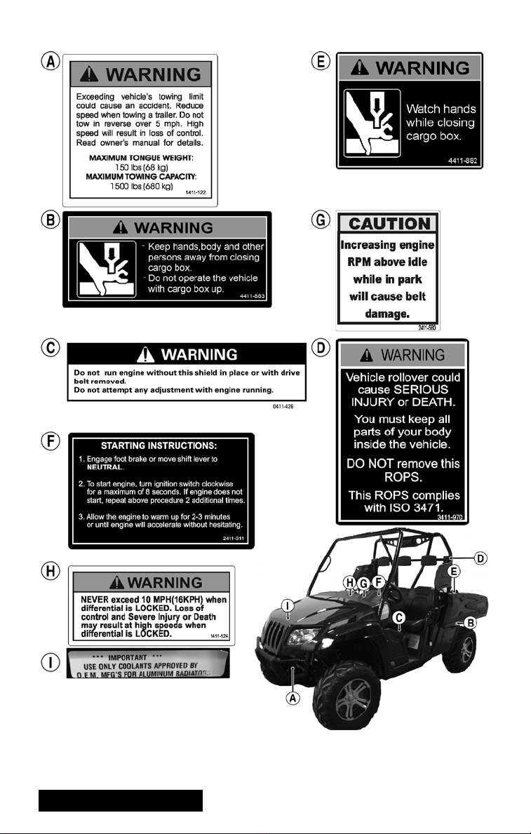
Warning and Instructional Labels
HDX191E
Pour commander des Etiquettes de Mise en Garde gratuites, voyez votre détailant de
autorisé VTT Toro pour le numéro de pièce 2436-306.
! WARNING
Indicates a hazardous situation which, if not
avoided, could result in death or serious injury.
5
Page 8
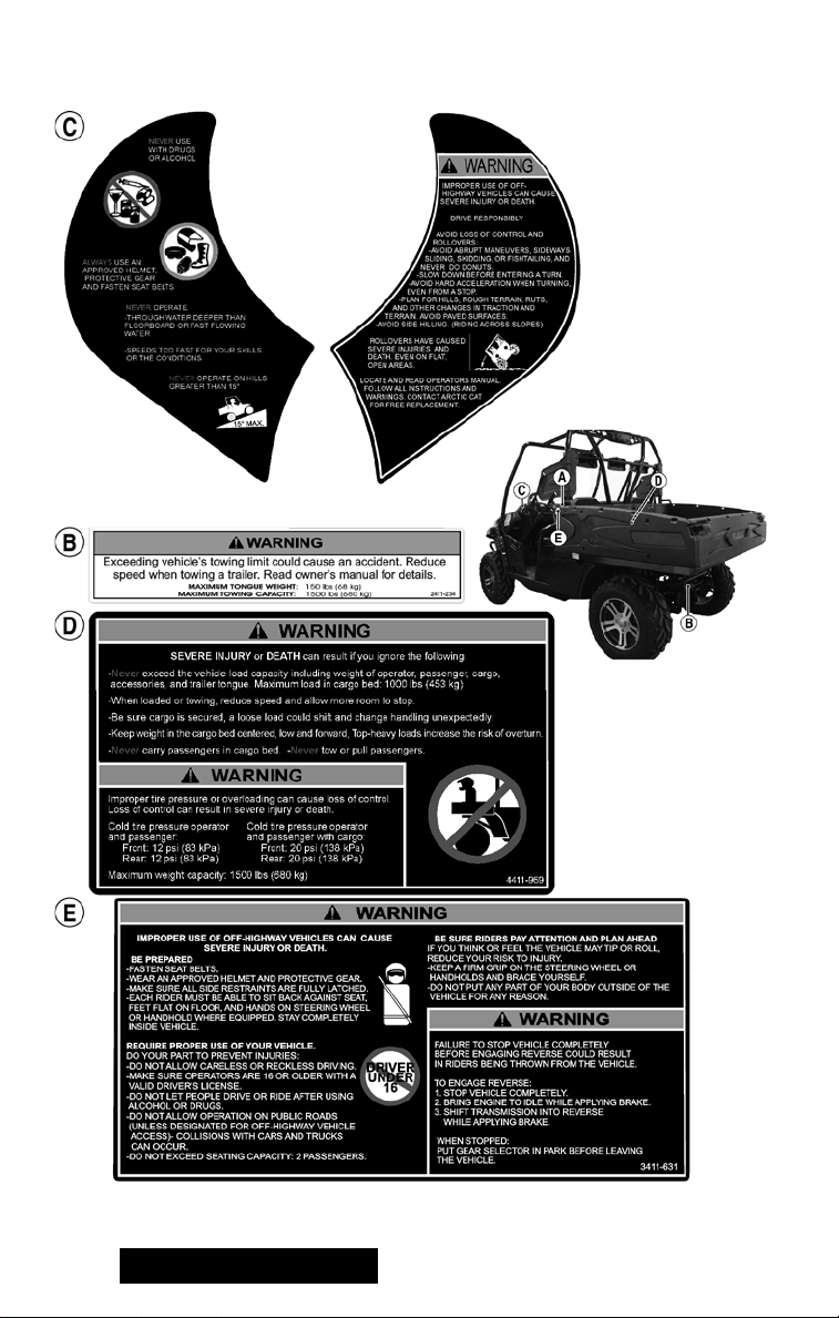
Warning and Instructional Labels
HDX189A
6
! WARNING
Indicates a hazardous situation which, if not
avoided, could result in death or serious injury.
Page 9
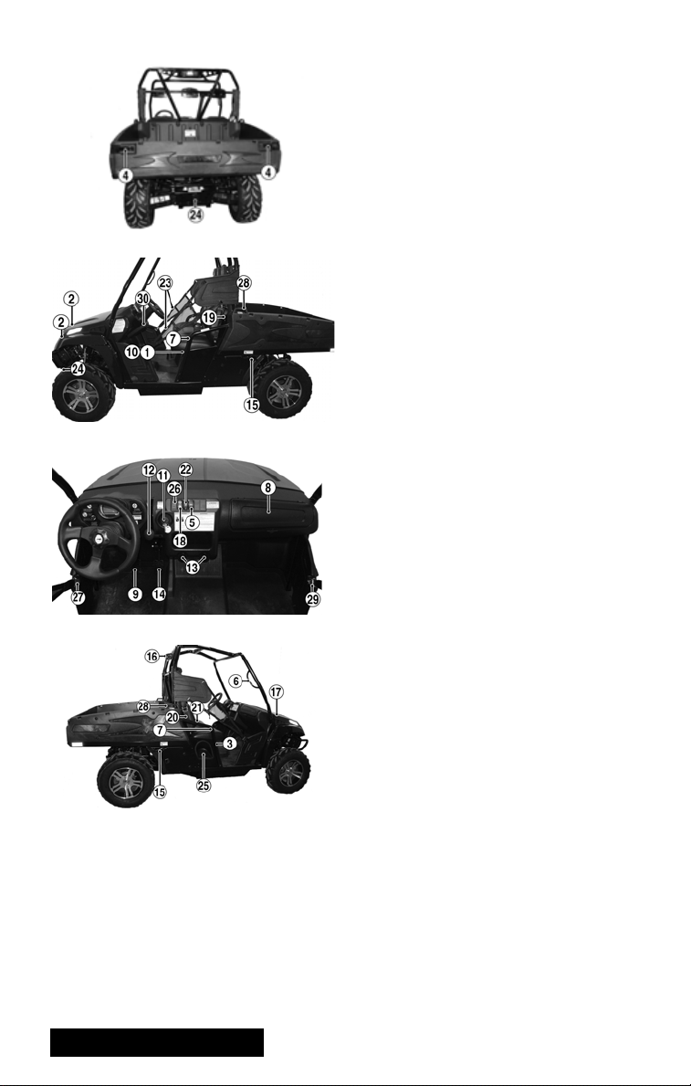
Location of Parts and Controls
1. Battery
2. Headlights
3. Tool Kit
4. Tailgate Latch
5. Reverse Override Switch
6. Outboard Passenger Hand Hold
HDX184A
TC001B
TC002A
TC003A
7. Hip Restraint Bar
8. In-Dash Storage Compartment
9. Brake Pedal
10. Fuses
11. Ignition/Start Switch
12. Shift Lever
13. DC Power Outlets
14. Accelerator Pedal
15. Cargo Box Latch Handle
16. Taillight/Brakelight
17. Operator’s Manual Location
18. Headlight Switch
19. Driver Seat Belt
20. Passenger Seat Belt (Right)
21. Passenger Seat Belt (Center)
22. Drive Select Switch
23. Occupant Side Restraints
24. Hitch Receiver
25. Gas Tank Cap
26. Seat Belt Reminder Indicator Light
27. Occupant Side Restraint Latch
28. Cargo Box Handle
29. Passenger Side Restraint Latch
30. Tilt Steering Lever
NOTE: The vehicle you purchased
may differ slightly from those
shown in the figures of this manual.
! WARNING
Indicates a hazardous situation which, if not
avoided, could result in death or serious injury.
7
Page 10

Warnings
! WARNING
POTENTIAL HAZARD
Operating this vehicle without proper instruction.
WHAT CAN HAPPEN
The risk of an accident is greatly increased if the operator does not know how to
operate this vehicle properly in different situations and on different types of terrain.
HOW TO AVOID THE HAZARD
All operators of this vehicle must read and understand this Operator’s Manual and
all warning and instruction labels prior to operating this vehicle.
! WARNING
POTENTIAL HAZARD
Allowing anyone under age 16 to operate this vehicle.
WHAT CAN HAPPEN
Use of this vehicle by children can lead to serious injury or death of the child.
Children under the age of 16 may not have the skills, abilities, or judgment needed
to operate this vehicle safely and may be involved in a serious accident.
HOW TO AVOID THE HAZARD
Only people 16 years of age or older with a valid driver’s license should operate
this vehicle.
! WARNING
POTENTIAL HAZARD
Allowing passengers to ride in the cargo bed.
WHAT CAN HAPPEN
Serious injury or death. This vehicle is not designed to carry passengers in the
cargo bed. Passengers in the cargo bed can be thrown around or from the vehicle
during operation or in an accident.
HOW TO AVOID THE HAZARD
Do not permit passengers to ride in the cargo bed. Do not install any seating in the
cargo bed.
! WARNING
POTENTIAL HAZARD
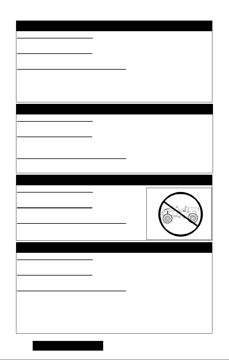
Operating this vehicle on public streets, roads, or highways.
WHAT CAN HAPPEN
You can collide with another vehicle.
HOW TO AVOID THE HAZARD
Never operate this vehicle on any public street, road, or highway.
In many states it is illegal to operate a vehicle of this type on public streets, roads,
or highways. Always check state and local laws and regulations.
8
! WARNING
Indicates a hazardous situation which, if not
avoided, could result in death or serious injury.
Page 11
Warnings
! WARNING
POTENTIAL HAZARD
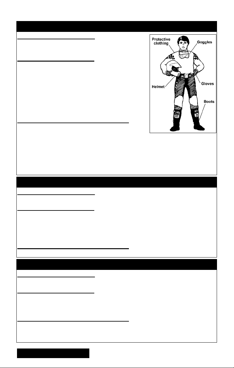
Operating this vehicle without wearing an approved
helmet, eye protection, and protective clothing.
WHAT CAN HAPPEN
Operating without an approved helmet increases your
chances of a serious head injury or death in the event
of an accident.
Operating without eye protection can result in an accident and increases your chances of a serious injury
in the event of an accident.
Operating without protective clothing increases your
chances of serious injury in the event of an accident.
HOW TO AVOID THE HAZARD
Always wear an approved helmet that fits properly.
You should also wear:
Eye protection (goggles or face shield)
Gloves
Boots
Long sleeved shirt or jacket
Long pants
! WARNING
POTENTIAL HAZARD
Operating this vehicle after or while consuming alcohol or drugs.
WHAT CAN HAPPEN
Could seriously affect your judgment.
Could cause you to react more slowly.
Could affect your balance and perception.
Could result in an accident.
HOW TO AVOID THE HAZARD
Never consume alcohol or drugs before or while driving this vehicle.
! WARNING
POTENTIAL HAZARD
Operating or riding in the vehicle without wearing a properly-secured seat belt.
WHAT CAN HAPPEN
Serious injury or death. Occupants can strike objects in the passenger compartment, fall out of the vehicle during maneuvers, or be crushed or otherwise injured
in the event of an accident.
HOW TO AVOID THE HAZARD
ALWAYS WEAR YOUR SEAT BELT and require others to wear their seat belts. See
the Operation/Maintenance section of this manual for more information on using
your seat belt and both operator and passenger(s) wearing an approved helmet.
! WARNING
Indicates a hazardous situation which, if not
avoided, could result in death or serious injury.
9
Page 12

Warnings
! WARNING
POTENTIAL HAZARD
Operating or riding in the vehicle without occupant side restraints properly
secured.
WHAT CAN HAPPEN
Serious injury or death. Occupants or their body parts can strike objects outside
the vehicle, be crushed by the vehicle, or fall out of the vehicle during maneuvers
or in the event of an accident.
HOW TO AVOID THE HAZARD
Do not remove the occupant side restraints. Make sure both driver and passenger
occupant side restraints are secure before operating or riding in the vehicle. Stay
seated with your seat belt and helmet on and keep your body completely inside the
vehicle during operation. See the Operation/Maintenance section of this manual
for more information.
! WARNING
POTENTIAL HAZARD
Failing to keep all parts of your body inside the passenger compartment during
operation.
WHAT CAN HAPPEN
Serious injury or death. Body parts could strike objects outside of vehicle or be
crushed in the event of a rollover or accident.
HOW TO AVOID THE HAZARD
Do not place your head, arms, hands, legs, or feet outside of the passenger compartment during operation. Stay seated with your seat belt and helmet on and
occupant side restraints properly secured. Keep your feet and legs inboard of the
foot restraints at all times. Do not attempt to stop movement or tipping of the vehicle with your hands or feet. Keep all body parts inside the passenger compartment. If you feel the vehicle tipping, brace your feet flat on the floor and keep
hands firmly gripping the steering wheel and the outboard passenger must hold on
to the hand hold.
! WARNING
POTENTIAL HAZARD
Operating this vehicle at excessive speeds.
WHAT CAN HAPPEN
Increases your chances or losing control of the vehicle, which can result in an accident.
HOW TO AVOID THE HAZARD
Always ride at a speed that is proper for the terrain, visibility, load, and operating
conditions.
10
! WARNING
Indicates a hazardous situation which, if not
avoided, could result in death or serious injury.
Page 13

Warnings
! WARNING
POTENTIAL HAZARD
Attempting abrupt maneuvers, sideways sliding, skidding, fishtailing, or donuts.
WHAT CAN HAPPEN
Increases the chance of an accident including a rollover.
HOW TO AVOID THE HAZARD
Never attempt abrupt maneuvers, sideways sliding, skidding, fishtailing, or donuts.
Don’t try to show off.
! WARNING
POTENTIAL HAZARD
Failure to inspect this vehicle before operating.
Failure to properly maintain this vehicle.
WHAT CAN HAPPEN
Increases the possibility of an accident or equipment damage.
HOW TO AVOID THE HAZARD
Always inspect this vehicle each time you use it to make sure it is in safe operating
condition.
Always follow the inspection and maintenance procedures and schedules
described in this Operator’s Manual.
! WARNING
POTENTIAL HAZARD
Failure to use extra care when operating this vehicle on unfamiliar terrain.
WHAT CAN HAPPEN
You can come upon hidden rocks, bumps, or holes without enough time to react.
Could result in the vehicle overturning or going out of control.
HOW TO AVOID THE HAZARD
Go slowly and be extra careful when operating on unfamiliar terrain.
Always be alert to changing terrain conditions when operating this vehicle.
! WARNING
POTENTIAL HAZARD
Failure to use extra care when operating on rough, slippery, or loose terrain.
WHAT CAN HAPPEN
Could cause loss of traction or control, which could result in an accident including
a rollover.
HOW TO AVOID THE HAZARD
Do not operate on rough, slippery, or loose terrain until you have learned and practiced the skills necessary to control this vehicle on such terrain.
Always be especially cautious on these kinds of terrain.
! WARNING
Indicates a hazardous situation which, if not
avoided, could result in death or serious injury.
11
Page 14
Warnings
! WARNING
POTENTIAL HAZARD
Failing to use care in turns; turning too sharply or aggressively.
WHAT CAN HAPPEN
The vehicle could go out of control causing a collision, tip over, or rollover.
HOW TO AVOID THE HAZARD
Always follow proper procedures for turning as described in this Operator’s Manual. Practice turning at slow speeds before attempting to turn at faster speeds. Do
not turn at excessive speed or too sharply for the conditions and for your experience level. See the Operation/Maintenance section of this manual for more information on turning on flat ground, hills, sand, ice, mud, or water.
! WARNING
POTENTIAL HAZARD
Operating on steep hills.
WHAT CAN HAPPEN
This vehicle can overturn more easily on steep hills than on level surfaces or small
hills.
HOW TO AVOID THE HAZARD
Never operate the vehicle on hills too steep for the vehicle or for your abilities.
Practice on smaller hills before attempting larger hills.
! WARNING
POTENTIAL HAZARD
Operating with the ROPS removed.
WHAT CAN HAPPEN
Could lead to serious injury or death.
HOW TO AVOID THE HAZARD
Never operate this vehicle with the ROPS removed.
! WARNING
POTENTIAL HAZARD
Going down a hill improperly.
WHAT CAN HAPPEN
Could cause loss of control or cause the vehicle to overturn.
HOW TO AVOID THE HAZARD
Always follow proper procedures for going down hills as described in this Operator’s Manual.
Always check the terrain carefully before you start down any hill.
Never go down a hill at high speed.
Avoid going down a hill at an angle that would cause the vehicle to lean sharply to
one side. Go straight down the hill where possible.
12
! WARNING
Indicates a hazardous situation which, if not
avoided, could result in death or serious injury.
Page 15
Warnings
! WARNING
POTENTIAL HAZARD
Climbing hills improperly.
WHAT CAN HAPPEN
Could cause loss of control or cause the vehicle
to overturn.
HOW TO AVOID THE HAZARD
Always follow proper procedures for climbing hills as described in this Operator’s
Manual.
Always check the terrain carefully before you start up any hill.
Never climb hills with slippery or loose surfaces.
Never open the throttle suddenly or make sudden gear changes. The vehicle could
flip over backwards.
Never go over the top of any hill at high speed. An obstacle, a sharp drop, or
another vehicle or person could be on the other side of the hill.
Never Operate Up Or
Down Hills Steeper
Than 15°
! WARNING
POTENTIAL HAZARD
Crossing hills or turning on hills.
WHAT CAN HAPPEN
Could cause loss of control or cause the vehicle to overturn.
HOW TO AVOID THE HAZARD
Never attempt to turn the vehicle around on any hill. If you must cross the side of a
hill, drive slowly and stop or turn downhill if you feel the vehicle may tip.
! WARNING
POTENTIAL HAZARD
Stalling, rolling backwards, or improperly dismounting while climbing a hill.
WHAT CAN HAPPEN
Could result in the vehicle overturning.
HOW TO AVOID THE HAZARD
Use proper gear and maintain steady speed when climbing a hill.
If you lose all forward speed:
Apply the brakes. Place the transmission in park after you
are stopped.
If you begin rolling backwards:
Apply the brakes while rolling backwards. When fully stopped, shift the
transmission into park.
! WARNING
Indicates a hazardous situation which, if not
avoided, could result in death or serious injury.
13
Page 16
Warnings
! WARNING
POTENTIAL HAZARD
Improperly operating in reverse.
WHAT CAN HAPPEN
You could hit an obstacle or person behind you, resulting in serious injury or death.
HOW TO AVOID THE HAZARD
Before you engage reverse gear, make sure there are no obstacles or people
behind you. When it is safe to proceed, go slowly.
! WARNING
POTENTIAL HAZARD
Improperly operating over obstacles.
WHAT CAN HAPPEN
Could cause loss of control or a collision. Could cause the vehicle to overturn.
HOW TO AVOID THE HAZARD
Before operating in a new area, check for obstacles.
Never attempt to ride over large obstacles, such as large rocks or fallen trees.
When you go over obstacles, always follow proper procedures as described in this
Operator’s Manual.
! WARNING
POTENTIAL HAZARD
Skidding or sliding.
WHAT CAN HAPPEN
You could lose control of the vehicle.
You could also regain traction unexpectedly, which may cause the vehicle to overturn.
HOW TO AVOID THE HAZARD
Learn to safely control skidding or sliding by practicing at slow speeds and on
level, smooth terrain.
On extremely slippery surfaces, such as ice, go slowly and be very cautious in
order to reduce the chance of skidding or sliding out of control.
! WARNING
POTENTIAL HAZARD
Operating the vehicle with improper tires or with improper or uneven tire pressure.
WHAT CAN HAPPEN
Use of improper tires on the vehicle, or operating the vehicle with improper or
uneven tire pressure, could cause loss of control increasing your risk of accident.
HOW TO AVOID THE HAZARD
Always use the size and type tires specified in this Operator’s Manual for this vehicle.
Always maintain proper tire pressure as described in this Operator’s Manual.
14
! WARNING
Indicates a hazardous situation which, if not
avoided, could result in death or serious injury.
Page 17
Warnings
! WARNING
POTENTIAL HAZARD
Overloading the vehicle or carrying or towing cargo improperly.
WHAT CAN HAPPEN
Could cause changes in handling, which could lead to an accident.
HOW TO AVOID THE HAZARD
Never exceed the stated load capacity for this vehicle.
Cargo should be properly distributed and securely attached.
Reduce speed when carrying cargo or pulling a trailer. Allow greater distance for braking.
Always follow the instructions in this Operator’s Manual for carrying cargo or pull-
ing a trailer.
! WARNING
POTENTIAL HAZARD
Operating this vehicle through deep or fast flowing water.
WHAT CAN HAPPEN
Tires may float, causing loss of traction and loss of control, which could lead to an
accident.
HOW TO AVOID THE HAZARD
Never operate this vehicle in fast flowing water or in water deeper than the floorboard.
Remember that wet brakes may have reduced stopping capability.
Test the brakes after leaving water. If necessary, apply them several times to dry
out the pads.
! WARNING
POTENTIAL HAZARD
Operating this vehicle with improper modifications.
WHAT CAN HAPPEN
Improper installation of accessories or modification of the vehicle may cause
changes in handling which, in some situations, could lead to an accident.
HOW TO AVOID THE HAZARD
Never modify this vehicle through improper installation or improper use of accessories.
All parts and accessories added to this vehicle should be genuine Toro components
designed for use on this vehicle and should be installed and used according to instructions. If you have questions, consult an authorized Toro ROV dealer.
! WARNING
Indicates a hazardous situation which, if not
avoided, could result in death or serious injury.
15
Page 18

Warnings
! WARNING
POTENTIAL HAZARD
Operating through or over thick or sharp brush, timber, debris, or rocks.
WHAT CAN HAPPEN
Serious injury or death. Brush, branches, debris, and rocks can enter or penetrate the passenger compartment and strike occupants. Running over sharp
branches, rocks, or other large objects can also cause loss of control.
HOW TO AVOID THE HAZARD
Be alert. Slow down. Wear all recommended protective gear specified in this Operator’s Manual. Avoid operating through or over thick brush, timber, debris, or large
rocks whenever possible. Watch for and avoid sharp branches, rocks, or other
large objects that could impede or impact the vehicle or enter the passenger compartment.
! WARNING
POTENTIAL HAZARD
Operating the vehicle with differential lock engaged.
WHAT CAN HAPPEN
The increased steering effort and reduced maneuverability caused by the locked
differential could result in loss of control and an accident.
HOW TO AVOID THE HAZARD
Never exceed 10 MPH (16 KPH) with the differential lock engaged. Always disengage the differential lock as soon as not needed for additional traction.
! WARNING
POTENTIAL HAZARD
Failing to avoid pinch-points when lowering the cargo box.
WHAT CAN HAPPEN
Fingers, hands, or arms could be seriously injured when lowering the cargo box.
HOW TO AVOID THE HAZARD
Always be aware of and avoid lowering cargo box until everyone is clear of pinchpoints.
! WARNING
POTENTIAL HAZARD
Securing a person improperly in the vehicle due to physical size.
WHAT CAN HAPPEN
Serious injury or death. Occupant could strike objects in the passenger compartment, fall out of the vehicle during maneuvers, or be ejected and crushed in the
event of an accident.
HOW TO AVOID THE HAZARD
Always make sure a passenger can sit with both feet flat on the floor and their back
against the seat while being able to reach any provided hand holds.
16
Page 19

DIVISION II - OPERATION/
MAINTENANCE
Specifications
ENGINE
Type Four-Cycle/Liquid Cooled
Bore x Stroke 102 mm x 85 mm (4.01 x 3.4 in.)
Displacement 695 cc (42.4 cu in.)
Spark Plug Type NGK CPR8E
Spark Plug Gap 0.5-0.6 mm (0.019-0.024 in.)
Brake Type Four Wheel Hydraulic
CHASSIS
Length (Overall) 327.6 cm (129.0 in.)
Height (Overall) 200.6 cm (79.0 in.)
Width (Overall) 152.4 cm (60 in.)
Suspension Travel (Front/Rear) 25.4 cm (10 in.)
Tire Size (Front) 26 x 9R-14
Tire Size (Rear) 26 x 11R-14
Tire Inflation Pressure 138 kPa (20 psi)
MISCELLANY
Dry Weight (Approx) 618 kg (1363 lb)
ROPS Tested Curb Weight 680 kg (1500 lb)
Gas Tank Capacity 31 L (8.2 U.S. gal.)
Coolant Capacity 2.9 L (3.0 U.S. qt)
Differential Capacity 275 ml (9.3 fl oz)
Rear Drive Capacity 250 ml (8.5 fl oz)
Engine Oil Capacity (Approx) 1.9 L (2.0 U.S. qt)
Gasoline (Recommended) 87 Octane Regular Unleaded
Engine Oil (Recommended) Toro 0W-40 All Weather Synthetic
Front Differential/Rear Drive Lubricant SAE Approved 80W-90 Hypoid
Brake Fluid DOT 4 Approved
Taillight/Brakelight 12V/8W/27W
Headlight 12V/27W (4)
Starting System Electric
Specifications subject to change without notice.
17
Page 20

Vehicle Operation
Pre-Start/Pre-Operation Checklist
Item Remarks
Brake System Pedal firm - near top of travel.
Controls Steering free - no binding - no excessive free-play.
Fluids Coolant level to the bottom of the stand pipe in the radiator neck.
Suspension Ball joints/tie rod ends free - secure.
Lights/Switches Check headlight HI/LO beam - light switch to OFF.
Air Filter Duck bill drains clear of all debris.
Tires/Wheels Properly inflated - tread adequate.
Seat Belts/Restraints Check condition - proper operation - proper adjustment.
Nuts/Bolts/Fasteners Check for loose nuts - bolts - tighten as necessary.
Fluid at proper level.
Check for fluid leaks.
Shift lever in park.
Accelerator free - no binding - returns to idle position.
Check oil level.
Gas tank full of recommended gasoline.
Differential/rear drive at proper level.
Check for fluid leaks.
Shocks not leaking - mountings secure.
Shock spring pre-load equal on left and right.
Components free of all debris.
Check taillight/brakelight - light switch to OFF.
Check drive select switch - set to 2WD.
Ducting secure - no holes or tears.
Check tires for cuts or tears.
Wheels secure to hubs - hubs secure to axles.
Check wheels for cracked or bent rims.
Check fasteners - latches - ROPS.
Secure hood, cargo box, seats.
18
Page 21
Starting the Vehicle
Always start with the vehicle on a flat,
level surface. Carbon monoxide poisoning can kill you, so keep the vehicle outside while it’s running. Follow these
steps to start it up:
1. Step into the vehicle and sit down; then
fasten the operator seat belt and the
passenger seat belts (if applicable) and
strap on your approved helmet and
require your passengers to do the same
(if applicable). Check that the occupant
side restraints are secured in place.
! WARNING
Falling from a moving vehicle could
result in serious injury or death.
Always fasten your seat belt securely
and ensure the passenger seat belt is
properly and securely fastened prior
to operating or riding in this vehicle.
2. Shift into park.
3. Depress the brake pedal.
4. Turn the ignition switch clockwise to
the START position; then when the
engine starts, release to the RUN
position. Do not increase engine RPM
above idle.
CAUTION
Increasing engine RPM above idle
while in Park will cause belt damage.
Shifting the
Continuously Variable
Transmission (CVT)
CAUTION
Always come to a complete stop
before attempting to shift from one
range to the other or into reverse or
park. Always shift on level ground or
apply the brakes.
NOTE: The CVT is fully automatic
and shifts as a function of engine
RPM and vehicle loading.
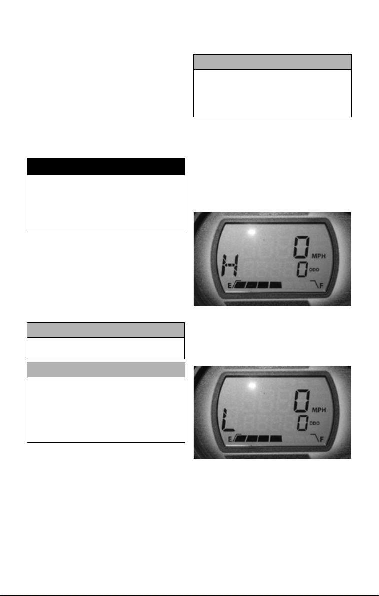
1. To select high range from park, move
the shift lever upward through reverse
and neutral until the letter “H” is displayed on the liquid crystal display
(LCD).
TC038
2. To select low range from high range,
move the shift lever upward one position until the letter “L” is displayed
on the LCD.
CAUTION
Do not run the starter motor for more
than eight seconds per starting
attempt. The starter motor may overheat causing severe starter motor
damage. Allow 15 seconds between
starting attempts to allow the starter
motor to cool.
5. Let the engine warm up.
TC039
NOTE: The high range is for nor-
mal driving with light loads. The low
range is for carrying heavy loads or
trailer towing. Compared to HIGH
range, the LOW range position provides slower speed and greater
torque to the wheels.
19
Page 22

CAUTION
Always shift into low range when
operating on wet or uneven terrain,
when towing or pushing heavy loads,
and when using a plow. Failure to follow this caution may result in premature V-belt failure or in damage to
related drive system components.
3. To select reverse gear from park,
move the shift lever upward one position until the letter “R” is displayed
on the LCD.
TC040
4. To select neutral from park, move the
shift lever upward two positions until
the letter “N” is displayed on the LCD.
TC041
5. To select park, move the shift lever
completely down until the letter “P”
is displayed on the LCD gauge.
CAUTION
Never increase engine speed above
idle RPM when in park or belt damage
will occur.
Driving the Vehicle
Once the engine is warm, the vehicle is
ready to be driven.
1. With the engine idling, press the foot
brake pedal to apply the brake; then
select the appropriate operating range
and/or direction with the shift lever.
2. Release the foot brake pedal and
press the accelerator to slowly add
power to start moving.
3. To slow down or stop, release the
accelerator and press the foot brake
pedal as necessary to slow or stop the
vehicle.
Braking/Stopping
Always allow plenty of room and time to
stop smoothly. Sometimes quick stops
are inevitable, so always be prepared.
Whether you’re stopping slowly or stopping quickly, do this:
1. Release the accelerator; then press the
foot brake pedal to apply the brake.
2. If the wheels lock, release them for a
second; then apply them again. On
surfaces such as ice, mud, or loose
gravel, pump the brake pedal rapidly.
3. Never “ride” the brake. Even maintaining minimal pressure on the brake
pedal will cause the brake pads to
drag on the disc and may overheat the
brake fluid.
! WARNING
Excessive repetitive use of the
hydraulic brake for high speed stops
will cause overheating of the brake
fluid and premature brake pad wear
which will result in an unexpected
loss of brakes.
20
TC042
Page 23

! WARNING
Use only DOT 4 approved brake fluid.
Never substitute or mix different
types or grades of brake fluid. Brake
loss can result. Check brake fluid
level and pad wear before each use.
Brake loss can result in serious
injury or death.
Parking
Parking involves following the previous
rules for braking; then:
1. After the vehicle stops, shift into park.
2. Then turn off the ignition.
! WARNING
Avoid parking this vehicle on hills.
The shift lever could inadvertently be
moved from park and allow the vehicle to roll downhill causing personal
injury or property damage.
3. If you have to park on a hill, shift to
park and block the wheels on the
downhill side.
Basic Turns
Steering effort is at its lowest in two-wheel
drive (2WD). Greater effort is needed when
in four-wheel drive (4WD). The greatest
effort is needed when in four-wheel drive
and the differential is locked. Never exceed
16 kph (10 mph) in the LOCK position.
Slow down before entering a turn. The
basic turning technique is to drive at low
speed and gradually adjust the amount of
steering to suit the driving surface. Do
not make sudden sharp turns on any surface. Refer to the sub-sections Driving
Uphill, Driving Downhill, Crossing
Obstacles, Driving in Reverse, Skidding
or Sliding, Crossing Water, or Crossing
Roads for more information.
If your vehicle ever skids sideways
during a turn, steer in the direction of the
skid. Also, avoid hard braking or accelerating until you have regained directional
control.
! WARNING
Use care in turns - turning the steering
wheel too far or too fast can result in
loss of control or a rollover. Excessive
speed, driving aggressively, or making
abrupt maneuvers, even on flat, open
areas, can cause loss of control, tipping, or rollover. Uneven terrain, rough
terrain, soft surfaces, slippery surfaces, and paved surfaces can also
cause a loss of control or rollover in a
turn. On loose or soft surfaces, allow
yourself more time and distance to
turn and slow down.
Driving Uphill
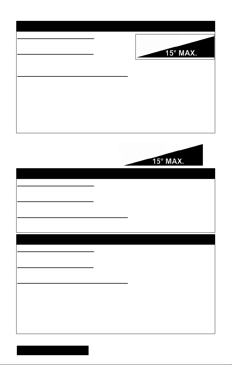
Always drive straight up the hill and
always avoid hills steeper than 15°.
1. Keep both hands on the wheel.
2. Prior to starting the climb, shift into
low range, select four-wheel drive for
traction, and gradually press the accelerator; then maintain a constant speed.
! WARNING
Do not attempt to turn around on a hill.
! WARNING
Driving up hills improperly can cause
loss of control of the vehicle resulting in serious injury or even death.
Use extreme care when driving in
hilly terrain.
3. If the vehicle stalls on a hill, press
the foot brake pedal to apply the
brake, shift into reverse, and slowly
back down the hill. Do not attempt
to turn around on a hill.
NEVER OPERATE UP OR DOWN HILLS STEEPER THAN 15°
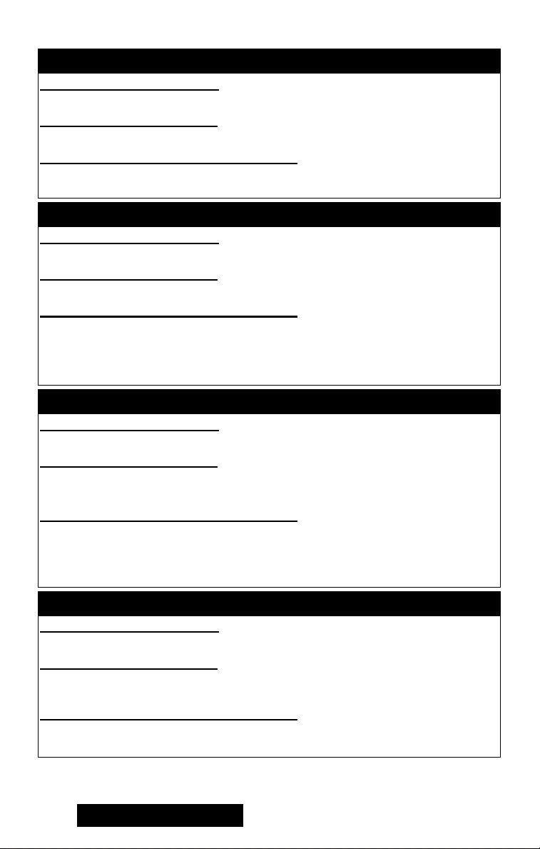
Driving Downhill
Always drive straight down the hill and
always avoid hills steeper than 15°.
1. Keep both hands on the wheel.
21
Page 24

2. Prior to descending the hill, shift into
low range and release the accelerator
to allow maximum engine braking.
Do not use four-wheel drive when
descending a hill. Engine braking can
cause the front wheels to slide reducing steering control.
NOTE: Use minimum braking (as
necessary) to maintain a slow speed.
! WARNING
Do not attempt to turn around on a hill.
! WARNING
Driving down hills improperly can
cause loss of control of the vehicle
resulting in serious injury or death.
Never drive downhill at a high rate of
speed. Use extreme care when driving in hilly terrain.
Crossing Obstacles
Crossing obstacles can be hazardous.
There is always the possibility of the
vehicle tipping. If you cannot go around
an obstacle, follow these guidelines:
1. Stop the vehicle and shift into park.
Go out to inspect the obstacle thoroughly from both your approach side
and the exit side. If you believe you
can cross the obstacle safely, select
four-wheel drive (4WD).
NOTE: Selecting the LOCK posi-
tion on the differential lock control
may be beneficial; however, steering effort will be greatly increased.
2. Approach the obstacle as close as possible to 90° to minimize vehicle tipping.
3. Keep speed slow enough to maintain
control but fast enough to maintain
momentum.
4. Use only enough power to cross the
obstacle but still give yourself plenty
of time to react to changes in conditions. Crawl over the obstacle.
! WARNING
Striking hidden obstacles can cause
serious injury or death. Reduce
speed and proceed with care in unfamiliar terrain.
22
NOTE: If there is any question
about your ability to cross the obstacle safely, you should turn around if
the ground is flat and you have room
or back up until you find a less difficult path.
Driving in Reverse
When operating in reverse, avoid sharp
turns and backing down a hill. When
using reverse, follow these guidelines:
1. Back up slowly. It’s hard to see
behind you.
NOTE: Avoid sudden braking
while backing up.
2. If possible, it is advisable to have
someone “spotting” for you while
backing up.
3. If you are unsure of what is behind
the vehicle, place the transmission in
park and get out and inspect the area
behind.
Skidding or Sliding
If you lose control after hitting sand, ice,
mud, or water, follow these guidelines:
1. Turn the steering wheel into the direction of the slide.
2. Keep your foot off the brake until
you’re out of the skid.
3. Stop and shift into four-wheel drive.
Crossing Water
This vehicle can only operate in water up
to its floorboard. Stay away from fast
moving rivers. This vehicle’s tires can be
buoyant. In deep water, the vehicle may
lose traction due to floating.
1. Physically check the depth and current
of the water, especially if you can’t see
the bottom. Also, check for boulders,
logs, or any other hidden obstacles.
2. Keep speed slow while maintaining
momentum.
3. Make sure you have a way out on the
other side of the water.
4. Once you’ve cleared the water,
briefly apply the brakes to make sure
they work.
Page 25

NOTE: Light pedal pressure or
pumping the brakes for a short distance will aid in drying the brakes.
2. If the tires are frozen to the ground,
pour warm water around them to melt
the ice.
Crossing Roads
It may be necessary to cross a road or highway. If so, note the following guidelines.
1. Stop completely on the shoulder of
the road.
2. Check both directions for traffic.
3. Crossing near a blind corner or intersection is dangerous; avoid it if at all
possible.
4. Drive straight across to the opposite
shoulder.
5. Take into account that this vehicle
could stall while crossing; give yourself enough time to get off the road.
6. You have to assume that oncoming
cars don’t see you, and if they do, they
won’t be able to predict your actions.
7. It’s illegal to cross public roads in
some places. Know your local laws.
Cold Weather Driving
NOTE: Check that all control levers
and the pedals move freely. Make
sure that the floorboard is free of ice
and snow.
! WARNING
For your personal safety, it is very
important to wear the type and amount
of cold-weather clothing according to
the coldest anticipated temperatures.
1. With the transmission in neutral, move
the vehicle forward and backward to
check that the wheels roll freely. If the
vehicle will not roll, the tires may be
frozen to the ground or the brake pads
may be frozen to the discs.
CAUTION
Before riding, manually move the
vehicle forward and backward to
make certain that all wheels roll freely.
3. If the brakes are frozen, use a suitable
heating device to thaw out the brakes.
! WARNING
Do not attempt to free frozen brakes
by pouring warm water on the brake
pads and housings.
NOTE: After the brakes thaw, dry
them by applying them several
times while riding slowly.
NOTE: After riding through water,
mud, snow, or slush, it is important
to dry the brakes before parking the
vehicle.
! WARNING
Go slowly and be extra careful when
riding on snow-covered or ice-covered terrain. Always be alert to
changing terrain conditions when
operating the vehicle.
! WARNING
Do not operate this vehicle on a frozen body of water. The vehicle could
break through the ice causing serious injury or death.
4. Practice driving in an open snow-covered or ice-covered area at slow
speeds before driving on snow-covered or ice-covered trails.
5. Learn how the vehicle responds to
steering and braking on the type of
terrain to be encountered on the ride.
23
Page 26

General Information
Control Locations and Functions
Ignition Switch Key
Two keys come with this vehicle. Keep
the spare key in a safe place.
Ignition Switch
The ignition switch has three positions.
ATV-0056A
OFF position — All electrical circuits
except the accessory are off. The engine
will not start. The key can be removed in
this position.
NOTE: The accessory plugs are
powered by the battery at all times.
RUN position — The ignition circuit is
complete and the engine can run. The key
cannot be removed in this position.
START position — The ignition circuit
is complete and the starter is engaged.
When the key is released, the switch will
return to the RUN position. The key cannot be removed in this position.
NOTE: This vehicle has safety
interlock switches which prevent
the starter motor from activating
when the transmission is not in
neutral. Depress and hold the brake
pedal to engage starter when the
transmission is not in neutral.
Shift Lever
This vehicle is equipped with a constant
velocity transmission (CVT) coupled to a
dual-range transmission with reverse and
park.
TC037
Drive Select Switch
HDX108C
This switch allows the operator to operate the vehicle in either two-wheel drive
(rear wheels) or four-wheel drive (all
wheels) as well as mechanically lock the
differential to apply equal power to both
front wheels. For normal riding on flat,
dry, hard surfaces, two-wheel drive
should be sufficient. In situations when
additional traction is necessary, fourwheel drive would be the desired choice.
To select 2WD, depress the bottom of the
switch. To select 4WD, move the switch
to the middle position. To engage the differential lock, slide the switch latch
slightly downward while pressing the top
of the switch forward.
CAUTION
Do not attempt to either engage or
disengage the front differential while
the vehicle is moving.
24
Page 27

NOTE: When the differential lock
is engaged, the indicator light will be
illuminated.
! WARNING
The differential lock is intended for use
where minimum traction is available.
NEVER EXCEED 16 kph (10 MPH)
the front differential lock engaged.
Maneuverability and handling characteristics will differ with the differential
lock engaged. Control loss can result
in serious injury or death.
with
Foot Brake
The foot brake is the only service brake,
and it should be applied whenever braking is needed.
Apply the brake by pressing the brake
pedal down.
Tilt Steering Latch
Pull on the lever located on the steering
column and move the steering wheel to
the desired position; then release the
lever and make sure the steering wheel
locks securely.
WT002A
! WARNING
Make sure the steering wheel is locked
securely in place before moving the
vehicle, or steering wheel movement
could occur causing loss of control.
PR880A
! WARNING
Make sure the steering wheel is locked
securely in place before moving the
vehicle, or steering wheel movement
could occur causing loss of control.
Headlight Switch
HDX108A
Use the headlight switch to select the
high or low headlight beam. When the
switch is in the HI position, the high
beam will illuminate. When the switch is
in the LO position, the low beam will
illuminate.
Reverse Override Switch
This vehicle is equipped with a reverse
speed limiter system. When additional
RPM is needed in reverse, depress and
hold the override switch located on the
dash.
HDX108B
25
Page 28

NOTE: The vehicle must be in 4WD
to activate the reverse override.
! WARNING
Never activate the override switch
while the throttle is open as a loss of
control could result.
Accelerator Pedal
Press down on the pedal to increase
engine RPM and vehicle speed; release
the pedal to decrease engine RPM and
vehicle speed.
NOTE: This vehicle is equipped
with an RPM limiter that retards
ignition timing when maximum
RPM is approached. When the RPM
limiter is activated, it could be misinterpreted as a high-speed misfire.
Seat
1. To remove the seat, lift up on the
front of the seat; then slide it forward.
2. To lock the seat into position, slide
the rear of the seat into the seat retainers and push down firmly on the front
of seat. The seat must engage the
retainers and lock into position.
! WARNING
Make sure the seat is secure before
driving the vehicle. Serious injury or
death could result if the seat is not
properly secured.
NOTE: To remove the seat base
and seat back, first remove the four
screws securing the seat back and
set the seat back aside. Remove the
screws securing the seat base and
set the seat base aside.
Seat Belts
This vehicle is equipped with seat belts
for the operator and two passengers. To
fasten and release the seat belt properly,
use the following procedure.
1. Place the seat belt across your lap as
low as possible without twisting the
belt making sure the shoulder strap is
below the neck and across the chest.
! WARNING
Only appropriate-sized passengers
may ride in this vehicle. Passengers
must be able to place both feet flat on
the floor while keeping their back
against the back of the seat and holding on to available hand holds.
2. Push the latch-plate into the buckle
slot until it “clicks” and latches
securely. The belt will retract when
the buckle is released.
! WARNING
Falling outside a moving vehicle
could result in serious injury or
death. Always fasten your seat belt
securely and ensure the passenger
seat belt is properly and securely fastened prior to operating or riding in
this vehicle.
Occupant Side Restraints
In addition to the seat belts, there are leftand right-side restraints to restrict arms
or legs from extending outside the vehicle. The restraints should always be
secured when the vehicle is moving.
To secure the restraint, connect the
restraint buckle to the foot restraint latch
bracket. To release the restraint, press the
release button in the center of the buckle.
HDX187A
26
Page 29

HDX188
Cargo Box
The cargo box on this ROV can be converted to a “flat-bed” cargo platform. To
convert your cargo box to a flat-bed, use
the following procedure.
1. Remove all cargo from the box; then
remove the left and right forward tie
bolts.
TC006
2. Raise the cargo box; then loosen the
four retaining bolts securing the side
panels in the stake pockets; then
lower the box.
HDX113A
3. Open the tailgate and remove the
machine screws securing the stopcables to the tailgate. Note the correct
orientation of the bushings to the
cable ends and tailgate.
HDX114A
4. Lift off the left and right cargo box
panels; then remove the tailgate from
the cargo bed.
HDX112A
HDX117
HDX115A
27
Page 30

5. Remove the stake pocket retaining
bolts, jam nuts, and forward tie bolt
clip nuts and secure in a safe place
with the machine screws and bushings from the tailgate.
HDX116A
To convert flat-bed to cargo box, use the
following procedure.
1. Set the tailgate into position in the
cargo bed; then lift the cargo bed
making sure the tailgate clears any
receiver hitch attachments.
4. Install the left and right side clip nuts
onto the frame; then install and
tighten the forward tie bolts securely.
HDX116A
5. Tighten the four stake pocket retaining bolts to 34 N-m (25 ft-lb) making
sure the cargo box side panels are
resting firmly on the cargo bed; then
tighten the jam-nuts to 20 N-m (15 ftlb). Lower the cargo box.
HDX117A
2. Install the stake pocket retaining bolts
and jam nuts leaving clearance to
install side panel stakes.
HDX118A
3. Set the left and right cargo box side
panels into place on the cargo bed
engaging the stakes into the side
pockets.
28
HDX112A
HDX113A
HDX122
Page 31

6. Secure the tailgate stop-cables to the
tailgate with the machine screws and
bushings making sure the bushing
engages the cable as shown. Tighten
to 2.7 N-m (24 in.-lb).
HDX123
Cargo Box Tie Downs
The cargo box has numerous tie down
locations around the top perimeter.
Always secure cargo with tie down straps
to avoid shifting or damage to cargo.
1. To open the tailgate, pull the latch
handles (located on the end of the
tailgate).
2. To close the tailgate, lift up and push
forward firmly. Hook the latch bails and
push the handles forward over center.
TC009
Cargo Box Latch Handles
HDX094A
CAUTION
When using ratchet-type straps, do
not over tighten or damage to the
cargo box could occur.
NOTE: Always refer to the Load
Capacity Ratings chart in this manual when loading and hauling cargo.
Tailgate Latches
TC010
TC008A
1. To raise the cargo box, lift the latch
handle upward; then raise the cargo
box.
HDX094
2. To lower the cargo box, use the box
handle to push down firmly on the
front of the box. The box will automatically lock into position and an audible
“click” will be heard.
29
Page 32

Power Steering
Certain vehicles were produced with an
Electronic Power Steering (EPS) system
to reduce steering effort and driver
fatigue over a broad range of operating
conditions.
The EPS system engages when the ignition switch is turned to the ON position
and disengages after approximately five
minutes (to conserve battery power) if
the engine is not running.
This system is entirely maintenance-free:
no adjustment or servicing is required.
There are no fluids to check or change,
and the EPS system is entirely self-contained and sealed to protect it from the
elements.
The EPS system is battery system powered; therefore, the battery must be in
good condition and fully charged. Power
delivery and overload protection is provided by an EPS relay and 30-amp fuse
located under the passenger seat in the
Power Distribution Module (PDM).
The system is self-monitored and will
display a malfunction code on the LCD
gauge/speedometer should an EPS system control circuit problem occur. Do not
operate the vehicle with an EPS malfunction code displayed.
Code Fault Description
C1301 Over Current
C1302 Excessive Current Error
C1303 Torque Sensor Range Fault
C1304 Torque Sensor Linearity Fault
C1305 Rotor Position Encoder
C1306 System Voltage Low
C1307 System Voltage High
C1308 Temperature Above 110° C
C1309 Temperature Above 120° C
C1310 Vehicle Speed High
C1311 Vehicle Speed Low
C1312 Vehicle Speed Faulty
C1313 Engine RPM High
C1314 Engine RPM Low
C1315 Engine RPM Faulty
C1316 EEPROM Error
C1317 CAN Bus Error
C1318 Internal CRC Error
C1319 Boot Counter Exceeded
Code Fault Description
C1320 Incorrect Vehicle Speed-to-RPM
C1321 Vehicle Speed Erratic
C1322 Engine RPM Lost
C1323 "EPS OFF" Gauge Display
C1324 Loss of CAN communication with
C1325 Dual Loss
C1326 Rotor Position Encoder
C1327 Voltage Converter Error (Low)
C1328 Voltage Converter Error (High)
C1329 Internal Data Error
Ratio
EPS unit
NOTE: Turn the key switch to the
OFF position then back to the ON
position to reset the malfunction
code. If the code continues to be displayed, take your vehicle to an authorized Toro ROV dealer for EPS system
servicing before resuming operation.
CAUTION
Never operate this vehicle with an
EPS code indicated on the LCD
gauge/speedometer. This indicates a
malfunction in the EPS system control circuit and could result in a loss
of power steering assist.
In the event of electrical power failure,
the EPS system becomes disabled (similar to an automobile with the engine shut
off). Steering effort increases but steering
control can be maintained.
Speedometer/LCD
TC015
1. Speedometer/Tachometer/Condition
Warning Display - Indicates the
approximate vehicle speed (MPH or
km/h) or RPM. Warns of a system
error condition requiring attention.
30
Page 33

The LCD will go blank except the
word VOLT will flash on the LCD
whenever a low voltage (<9 DC volts)
or a high voltage (>16 DC volts) is
detected. When voltage returns to normal, the gauge must be reset by turning
the ignition key to the OFF position
and then to the ON position.
A diagnostic trouble code (DTC) will
flash on the LCD whenever an electronic fuel injection (EFI) system
error is detected. After 30 seconds,
the gauge will return to normal, but
the code will continue to flash until
the malfunction is corrected.
NOTE: Take the ROV to an autho-
rized Toro ROV dealer to have the
error corrected and the system error
reset as soon as possible.
2. Fuel Level Indicator - Indicates
approximate amount of gasoline in
the gas tank.
NOTE: When the bottom segment
flashes, approximately 3.5 L (0.92 U.S.
gal.) of gasoline remains in the tank.
3. Mode Button - Press and release to
shift the gauge between MPH or km/h
and RPM. Press and hold to switch
between MPH and km/h.
4. Set/Reset Button - Press and release
to shift between Odometer, Trip 1,
Trip 2, Engine Hour Meter, and
Clock. Press and hold while Trip 1 or
Trip 2 are selected to clear the
selected trip. The odometer cannot be
reset.
5. Odometer/Trip Meter/Clock/Engine
Hour Meter - Displays odometer
(total distance the vehicle has traveled) or one of two trip meters used to
measure trips or trip legs corresponding to the function selected (MPH or
km/h). The clock function indicates
time in the 12 hour mode. The hour
meter indicates the total time the
ROV has run and cannot be reset to
zero. To set the clock, use the following procedure.
A. With the ignition switch ON, press
and release the Mode Button until
the Clock/Engine Hour Meter is
displayed; then (if necessary) press
and release the Set/Reset Button to
the clock display.
B. Press and hold Set/Reset Button
until minutes stop scrolling and the
hour display starts to scroll.
Momentarily release when correct
hour is displayed; then repeatedly
press and release Set/Reset Button
until correct minutes are displayed.
NOTE: Approximately two seconds
after releasing either Button, the
LCD will return to normal operation.
NOTE: Clock memory power is
supplied through the 15-amp accessory fuse and verified during gauge
“power-up” and reset. In the event of
clock memory power failure (blown
fuse, etc.), the gauge will “powerup,” reset, and shut down repeatedly
until clock memory power is
restored. Always check the 15-amp
accessory fuse if this gauge condition is noted.
NOTE: The engine hour meter will
not activate until engine speed
exceeds 500 RPM.
6. Gear Position Indicator - Indicates
which gear is selected - R (reverse)/N
(neutral)/H (high range)/L (low
range)/P (park).
NOTE: An E will be displayed if
there is an error caused by a no-shift
position signal.
7. Engine Hour Meter Indicator - Indicates engine hour meter mode is
selected on the display.
8. Speedometer/Tachometer Indicator Indicates which mode (MPH, km/h,
or RPM) is being displayed.
9. 4WD Lock Indicator - Displays
LOCK when the front differential
lock has been engaged.
10. Drive Select Indicator - Displays
4WD when selected by the drive
select switch or when the 4WD lock
is engaged. The display is blank when
in 2WD.
31
Page 34

11. High Beam Indicator - Appears when
the headlights are on high beam.
12. Temperature Indicator - The speedometer/tachometer needle will sweep full
scale and the LCD will go blank except
the high temperature icon will flash.
After 30 seconds, the speedometer/
tachometer needle and LCD will return
to normal, but the temperature icon will
continue to flash. The icon should not
be visible during normal operation.
13. Odometer/Trip Meter Indicator Display - Displays which function (ODO,
Trip, or Trip 2) is selected.
14. Wrench Indicator - Displayed in conjunction with a DTC whenever an
EFI system error is detected.
15. Seat Belt Indicator - Displayed whenever the driver’s seat belt is not fastened.
2. From the left side, unscrew the oil level
stick and wipe it with a clean cloth.
PR053B
3. Install the oil level stick.
NOTE: The oil level stick should be
threaded in for checking purposes.
4. Remove the oil level stick; the engine
oil level must be within the operating
range but not exceeding the upper mark.
TC036A
Electric Fuel Pump
An electric fuel pump is mounted in the
gas tank to deliver gasoline to the fuel
injector. The fuel pump operates when
the ignition switch is turned to the ON or
START position.
Gas Hoses
Replace the gas hose every two years. Damage from aging may not always be visible.
Oil Level Stick
There is an oil level stick for checking
the engine oil level. To check the oil
level, use the following procedure.
NOTE: The vehicle should be on
level ground when checking the
engine oil level.
1. Lift the cargo box.
32
GZ461A
5.To add oil, remove the seat, oil fill cap
access cover, and oil fill cap (using a
27 mm socket). After adding oil,
install the fill cap and tighten to 16 ftlb; then install the cover and seat.
HDX022A
CAUTION
Do not overfill the engine with oil.
Always make sure the oil level is
within operating range.
Page 35

Load Capacity Ratings
This vehicle must always be loaded in
accordance with the Load Capacity Ratings chart. Under no circumstances
should the Vehicle Load Capacity or the
Gross Vehicle Weight (GVW) rating ever
be exceeded.
! WARNING
Overloading this vehicle could result
in loss of control resulting in serious
injury or death.
Load Capacity Ratings
Item Specifications
Vehicle Load Capacity 1500 lb 680 kg
Tongue Weight 150 lb 68 kg
Rear Tongue and Cargo
Weight (max)
Towing Capacity 1500 lb 680 kg
1000 lb 454 kg
Vehicle Load Capacity - Total weight of
operator, passenger(s), trailer tongue
weight, accessories, and cargo.
Tongue Weight - Weight of trailer
tongue on hitch.
Accessory Weight - Winch, gun scabbard brackets, etc.
Rear Tongue and Cargo Weight - Total
weight of trailer tongue and cargo in the
box.
Towing Capacity - Total weight of
trailer and all cargo in the trailer.
Trailering and Towing
HDX062A
This vehicle is equipped with a framemounted receiver (front and rear) for a
standard 5.1 cm (2 in.) receiver hitch.
The standard receiver hitch must be purchased separately.
! WARNING
Make sure that the load in the trailer is
properly secured and will not shift while
moving. Also, do not overload the trailer.
When loading a trailer properly, two
items are critical: Gross Trailer Weight
(the weight of the trailer plus cargo) and
Trailer Tongue Weight.
! WARNING
Never exceed any of the vehicle
weight restrictions.
Trailer Tongue Weight is the downward
force exerted on the hitch by the trailer
coupler when the trailer is fully loaded
and the coupler is at its normal towing
height. Refer to the Load Capacity Ratings chart for tongue weight information.
Always maintain a slow speed when
trailering and towing and avoid sudden
accelerations, quick maneuvers, and sudden stops. Braking distance will be
affected when towing a trailer. When
towing a trailer, always maintain slow
speed and allow more stopping distance
than when not towing a trailer.
! WARNING
Driving this vehicle without extra caution when towing a trailer will be hazardous. Trailer towing can affect the
handling and braking of the vehicle.
Tow only at low speeds and never
exceed 16 kph (10 mph). Avoid sudden accelerations and stopping of
the vehicle. Do not make quick
maneuvers. Avoid uneven surfaces
and do not tow on hills. Never carry
passengers in a trailer unless the
trailer is designed for such use and
has a rigid tow bar. Allow more stopping distance than when not towing a
trailer.
33
Page 36

Transporting
NOTE: When transporting the
vehicle, make sure the vehicle is in
park.
This vehicle must be transported in its
normal operating position (on all four
wheels) and secured with hold-down
straps in the proper areas. Shown is the
minimum number of hold-down straps to
be used.
PR075A
! WARNING
Use extreme caution when operating
a machine on a ramp.
Ensure that the ROPS will clear the
top of an enclosed trailer.
Use only a full-width ramp; do not use
individual ramps for each side of the
machine.
Do not exceed a 15-degree angle
between the ramp and the ground or
between the ramp and the trailer or
truck.
Ensure the length of ramp is at least
four times (4X) as long as the height
of the trailer or truck bed to the
ground. This will ensure that ramp
angle does not exceed 15-degrees on
flat ground.
Avoid sudden acceleration or deceleration while driving the machine on
a ramp as this could cause a loss of
control or a tip-over situation.
PR073A
CAUTION
If using additional hold-down straps
in any other areas, care must be
taken not to damage the vehicle.
34
TC028
Gasoline-Oil-Lubricant
Recommended Gasoline
The recommended gasoline to use in this
vehicle is 87 minimum octane regular
unleaded. In many areas, oxygenates are
added to the gasoline. Oxygenated gasolines containing up to 10% ethanol or 5%
methane are acceptable gasolines.
Page 37

When using ethanol blended gasoline, it is
not necessary to add a gasoline antifreeze
since ethanol will prevent the accumulation of moisture in the fuel system.
CAUTION
Do not use white gas. Only recommended gasoline additives should be
used.
Recommended Engine/
Transmission Oil
CAUTION
Any oil used in place of the recommended oil could cause serious
engine damage. Do not use oils which
contain graphite or molybdenum additives. These oils can adversely affect
clutch operation. Also, not recommended are racing, vegetable, nondetergent, and castor-based oils.
The recommended oil to use is Toro 0W40 All Weather synthetic engine oil,
which has been specifically formulated
for use in this engine. Although Toro 0W40 All Weather synthetic engine oil is the
only oil recommended for use in this
engine, use of any API certified SM 0W40 synthetic oil is acceptable.
Recommended Front
Differential/Rear Drive
Lubricant
NOTE: Toro recommends the use
of genuine Toro lubricants.
The recommended front differential/rear
drive lubricant is SAE approved 80W-90
hypoid. This lubricant meets all of the
lubrication requirements of this vehicle.
CAUTION
Any lubricant used in place of the
recommended lubricant could cause
serious front differential/rear drive
damage.
Filling Gas Tank
! WARNING
Always fill the gas tank in a well-ventilated area. Never add gasoline to the
gas tank near any open flames or with
the engine running or hot. DO NOT
SMOKE while filling the gas tank.
Since gasoline expands as its temperature
increases, the gas tank must be filled to
its rated capacity only. Expansion room
must be maintained in the tank particularly if the tank is filled with cold gasoline and then moved to a warm area.
Allow the engine to cool before filling the
gas tank. Care must be taken not to overfill the tank past the full mark. If overfilled, gas may leak out creating a fire
hazard.
OILCHARTJ
NOTE: If the vehicle will be oper-
ated under severe conditions
(heavy pulling or loading, extremely
high ambient air temperatures, or
extended high-speed operation),
Toro recommends installing an
engine oil cooler kit if not so
equipped. For additional information, see your local authorized Toro
ROV dealer.
ROV353A
! WARNING
Do not over-flow gasoline when filling
the gas tank. A fire hazard could
materialize. Always allow the engine
to cool before filling the gas tank.
35
Page 38

Tighten the gas tank cap securely after
filling the tank.
! WARNING
Do not overfill the gas tank.
Engine Break-In
After the completion of the break-in
period, the engine oil and oil filter should
be changed. Other maintenance after
break-in should include checking of all
prescribed adjustments and tightening of
all fasteners. At the discretion and
expense of the owner/operator, the vehicle may be taken to an authorized Toro
ROV dealer for this initial service.
New vehicles and engines require a
“break-in” period. The first month is
most critical to the life of this vehicle.
Proper operation during this break-in
period will help assure maximum life and
performance from this vehicle.
During the first 10 hours of operation,
always use less than ½ throttle. Varying the
engine RPM during the break-in period
allows the components to “load” (aiding the
engine/transmission component mating
process) and then “unload” (allowing components to cool). Although it is essential to
place some stress on the engine components during break-in, care should be taken
not to overload the engine too often. Do not
pull a trailer during the break-in period.
When the engine starts, allow it to warm up
properly. Idle the engine several minutes
until the engine has reached normal operating temperature. Do not idle the engine for
excessively long periods of time.
Burnishing Brake Pads
Brake pads must be burnished to achieve
full braking effectiveness. Braking distance will be extended until brake pads are
properly burnished.
! WARNING
Do not attempt sudden stops or put
yourself into a situation where a sudden stop will be required until the
brake pads are properly burnished.
1. Choose an area sufficiently large to
safely accelerate to 50 km/h (30 mph)
and to brake to a stop.
2. Accelerate to 50 km/h (30 mph); then
press brake pedal to decelerate to 0-8
km/h (0-5 mph).
3. Repeat procedure twenty times.
36
Page 39

General Maintenance
NOTE: Proper maintenance of the
ROV is important for optimum performance. Follow the Maintenance
Schedule and all ensuing maintenance and care instructions/information.
NOTE: Proper maintenance pro-
cedures for each item can be found
on the corresponding page indicated.
If, at any time, abnormal noises, vibrations, or improper functioning of any
component of this vehicle is detected,
DO NOT OPERATE THE VEHICLE.
Take the vehicle to an authorized Toro
ROV dealer for inspection and adjustment or repair.
If the owner/operator does not feel qualified to perform any of these maintenance
procedures or checks, take the vehicle to
an authorized Toro ROV dealer for professional service.
37
Page 40

Maintenance Schedule
Item Page
Battery 44 I I
* Engine nuts and bolts — I I
* Valve clearance — I I
Spark plug 46 I I
Liquid cooling system 39 I Inspect every time before operating
Gas hoses 32 I Inspect every time before operating
Engine/transmission oil and filter 40 R R**
Air filter 47 I I
Gear lubricant
(front differential - rear drive)
V-B e lt 4 8 I I
Spark arrester/muffler 49 C
Tires/air pressure 48/17 I Inspect every time before operating
* Brake components 42 I Inspect every time before operating
Brake fluid 42 I *Replace every 2 years
Brake hoses 42 I *Replace every 4 years
* Steering — I Inspect every time before operating
* Suspension (Ball joint boots,
drive axle boots front and rear, tie
rods, differential and rear drive
bellows)
* Chassis nuts and bolts — I T
Wheel lug nuts 49 T T
Frame/welds/racks — I I
Electrical connections — I I
Headlight/taillight-brakelight 50 I Inspect every time before operating
Air filter drains — I Inspect every time before operating
Accelerator pedal 26 I Inspect every time before operating
ROPS 52 Inspect every time before operating
Occupant side restraints 52 Inspect every time before operating
Wheel nuts 49 I I
160 km
(100 miles)
46 Replace every 6500 km (4000 miles) or 18 months
32 Replace every 2 years
41 R I
41
— I Inspect every time before operating
Initial
Every
160 km
(100 miles)
Replace every 2 years or 3200 km
Every
480 km
(300 miles)
(2000 miles)
Every
800 km
(500 miles)
I = Inspect and clean, adjust, lubricate, replace as necessary
T = Tighten R = Replace C = Clean
* = Dealer maintenance
**When using Toro 0W-40 All Weather synthetic oil, oil change interval can be increased to
every 1600 km (1,000) miles or every year.
38
Page 41

Liquid Cooling System
NOTE: Debris in the engine compartment or packed between the cooling fins of the radiator can reduce
cooling capability. Using a garden
hose, wash the radiator to remove
any debris preventing air flow.
CAUTION
Do not use a pressure washer to clean
the radiator core. The pressure may
bend or flatten the fins causing
restricted air flow, and electrical components on the radiator could be damaged. Use only a garden hose with
spray nozzle at normal tap pressure.
The cooling system capacity can be found
in the specification charts. The cooling system should be inspected daily for leakage
and damage. If leakage or damage is
detected, take the vehicle to an authorized
Toro
ROV dealer for service. Also, the
coolant level should be checked periodically.
NOTE: High engine RPM, low vehicle speed, or heavy load can raise
engine temperature. Decreasing
engine RPM, reducing load, and
selecting an appropriate transmission gear can lower the temperature.
CAUTION
Continued operation of the vehicle with
high engine temperature may result in
premature wear or engine damage.
When filling the cooling system, use a
coolant/water mixture which will satisfy
the coldest anticipated weather conditions
of the area in accordance with the coolant
manufacturer’s recommendations.
NOTE: Use a good quality, biode-
gradable glycol-based, automotivetype antifreeze.
While the cooling system is being filled,
air pockets may develop; therefore,
remove the bleed plug on the coolant
pipe at the front of the engine allowing
trapped air to escape.
TC024A
When pure coolant (no air) flows from
the bleed hole, install the bleed plug,
tighten securely, and then fill the cooling
system to the bottom of the stand pipe in
the radiator neck. After operating the
vehicle for the initial 5-10 minutes, stop
the engine, allow the engine to cool
down, and check the coolant level. Add
coolant as necessary.
! WARNING
Never check the coolant level when
the engine is hot or the cooling system is under pressure.
Shock Absorbers
Each shock absorber should be visibly
checked weekly for excessive fluid leakage (some seal leakage may be observed
but it does not indicate the shock is in
need of replacement), cracks or breaks in
the lower case, or a bent shock rod. If any
one of these conditions is detected,
replacement is necessary.
NOTE: When the vehicle is oper-
ated in extremely cold weather (-23°C/
-10°F or colder), a small amount of
leakage may be present. Unless the
leakage is excessive, replacement is
not necessary.
This vehicle is equipped with adjustable
shock absorbers in the front and rear to
allow for different driving and loading
conditions.
The front shock absorbers have an adjustment sleeve with five preload adjustment
positions that can be turned with a special
spanner wrench to increase or decrease
coil spring tension.
39
Page 42

To adjust the spring force on the these
shock absorbers, rotate the pre-load
adjustment sleeve with a suitable spanner
wrench until desired spring tension is
achieved.
Position
Spring
Force
1
2
3
4
5
Stronger
Setting Load
Soft
Stiff
Light
Heavy
PR015
The rear shock absorber has a spring
force adjustment nut with an infinite
adjustment from softest to most firm. If
the spring action is too soft or too stiff,
adjust the nut using an appropriate spanner as illustrated.
General Lubrication
Cables
None of the cables require lubrication;
however, it is advisable to lubricate the
ends of the cables periodically with a
good cable lubricant.
Cargo Box Latches
Periodically apply a light coat of grease to
the latches and pins. Do not over grease.
Engine/Transmission Oil
and Filter
NOTE: Refer to the recommended
oil viscosity chart (on page 35) in
this manual for the proper engine oil.
Change the engine oil and oil filter at the
scheduled intervals. The engine should
always be warm when the oil is changed
so the oil will drain easily and completely.
1. Park the vehicle on level ground.
2. Remove the seat; then remove the
backrest and seat base.
3.
Loosen the oil fill cap using a 27 mm
socket. Be careful not to allow contaminants to enter the opening.
HDX085A
NOTE: Before attempting to
adjust suspension, clean dirt and
debris from the sleeve and remove
load from the suspension; then use
the spanner wrench to adjust the
sleeve to the desired position.
40
HDX042A
4. Remove the drain plug from the bottom of the engine and drain the oil
into a drain pan.
PR078A
Page 43
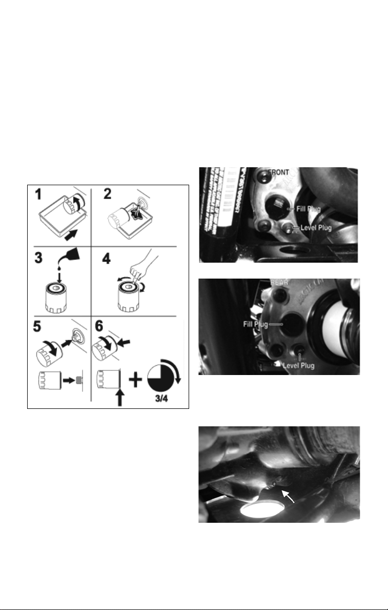
5. Use an appropriate oil filter wrench to
remove the old oil filter and dispose
of properly. Do not re-use oil filter.
NOTE: To access the filter,
remove the seat, seat back, and
seat base (see Seats in General
Information).
NOTE: Clean up any excess oil
after removing the filter.
6. Apply oil to the new filter O-ring and
check to make sure it is positioned
correctly; then install the new oil filter. Tighten 3/4 turn after contact with
the sealing flange.
11. Install the seat base, seat, and backrest.
Front Differential And
Rear Drive Gear Lubricant
(Inspecting/Changing)
Inspect and change the gear lubricant in
each according to the Maintenance
Schedule. When changing the lubricant,
use the following procedure.
1. Place the vehicle on level ground.
2. Remove the front differential and rear
drive fill plugs.
HDX083A
TC031
7. Install the engine drain plug and
tighten to 22 N-m (16 ft-lb). Pour the
recommended oil in the fill hole.
Install the oil fill cap.
8. Start the engine (while the vehicle is
outside on level ground) and allow it
to idle for a few minutes.
9. Turn the engine off and wait approximately one minute. Check the oil level
(see Oil Level Stick on page 32).
10. Inspect the area around the drain plug
and oil filter for leaks.
HDX084A
3. Drain the lubricant into a drain pan by
removing the drain plug from the
front differential and rear drive.
CF107A
41
Page 44

CF106A
4. After all the lubricant has been
drained, install the drain plugs and
tighten to 5 N-m (45 in.-lb).
CAUTION
Inspect the oil for any signs of metal
filings or water. If found, take the
vehicle to an authorized Toro ROV
dealer for servicing.
5. Pour SAE approved 80W-90 hypoid
lubricant into each fill hole until it
flows out of the hole.
6. Install the fill plugs and tighten to 22
N-m (16 ft-lb).
Hydraulic Brake
! WARNING
Be sure to inspect the hydraulic
brake system before each use.
Always maintain brakes according to
the Maintenance Schedule.
Brake Fluid
NOTE: The brake fluid reservoir is
located on top of the master cylinder under the hood.
2. Press the brake pedal several times to
check for firmness.
3. If the pedal is not firm, the system
must be bled.
NOTE: Take the vehicle to an autho-
rized Toro ROV dealer for this service.
CAUTION
Be careful not to spill any fluid when
filling the brake fluid reservoir. Wipe
away spilled fluid immediately.
Brake Hoses
Carefully inspect the hydraulic brake hoses
for cracks or other damage. If found, take
the vehicle to an authorized
dealer to have the brake hoses replaced.
Brake Pads
The clearance between the brake pads
and brake discs is adjusted automatically
as the brake pads wear. The only maintenance that is required is replacement of
the brake pads when they show excessive
wear. Check the thickness of each of the
brake pads as follows:
1. Remove a front wheel.
2. Measure the thickness of each brake
pad.
3. If thickness of either brake pad is less
than 1.0 mm (0.039 in.), take the
vehicle to an authorized
dealer to have brake pads replaced.
Toro
Toro
ROV
ROV
HDX081A
1. Check the brake fluid level in the brake
fluid reservoir. The fluid level must be
maintained between the MAX and MIN
level marks. If the level in the reservoir
is low, add DOT 4 approved brake fluid.
42
PR376B
Page 45

4. Install the wheel; then using a crisscross pattern, tighten the wheel nuts in
27 N-m (20 ft-lb) increments to the
final torque shown in the table below.
Steel Wheel 54 N-m
Aluminum Wheel (Black Nuts) 80 N-m
Aluminum Wheel (Chrome Nuts) 108 N-m
(40 ft-lb)
(60 ft-lb)
(80 ft-lb)
PR941A
CAUTION
Using an impact wrench could result
in incorrect torque which could damage the wheel or hub studs.
Protective Rubber Boots
The protective boots should be inspected
before each use.
Ball Joint Boots (Upper
and Lower/Right and Left)
4. Check the ball joint for free-play by
grasping the steering knuckle and
turning it from side to side and up and
down.
5. If boot damage is present or ball joint
free-play seems excessive, contact an
Toro
authorized
ROV dealer for service.
Tie Rod Boots (Inner and
Outer/Right and Left)
CC792
1. Secure the vehicle on a support stand
to elevate the front wheels.
2. Remove both front wheels.
3. Inspect the four tie rod boots for
cracks, tears, or perforations.
4. Check the tie rod end free-play by
grasping the tie rod near the end and
attempting to move it up and down.
5. If boot damage is present or tie rod end freeplay seems excessive, contact an authorized
Toro
ROV dealer for service.
Drive Axle Boots
CC791
1. Secure the vehicle on a support stand
to elevate the front wheels.
2. Remove both front wheels.
3. Inspect the four ball joint boots for
cracks, tears, or perforations.
CC793
1. Inspect the front and rear drive axle
boots for cracks, tears, or perforations.
2. If boot damage is present, contact an
authorized
Tor o
ROV dealer for ser-
vice.
43
Page 46

Battery
! WARNING
CALIFORNIA
Proposition 65 Warning
Battery posts, terminals, and related
accessories contain lead and lead
compounds, chemicals known to the
state of California to cause cancer
and reproductive harm. Wash hands
after handling.
NOTE: Refer to all warnings and
cautions provided with the battery
or battery charger.
This ROV is shipped with a sealed battery.
The battery requires an initial charge after
activation as well as periodic maintenancecharging during periods of non-use or storage.
NOTE: Maintenance charging is
required on all batteries not used
for more than two weeks or as
required by battery drain.
NOTE: The battery box is under
the seat on the operator’s side. To
access the box, remove the seat and
pry off the battery compartment
cover; then remove the thumb screw
securing the battery box cover and
lift the cover to access the battery.
PR943A
PR942
After being in service, batteries require
regular cleaning and recharging in order
to deliver peak performance and maximum service life. The following procedure is recommended for cleaning and
maintaining a sealed battery. Always read
and follow instructions provided with
battery chargers and battery products.
NOTE: Refer to all warnings and
cautions provided with the battery
or battery maintainer/charger.
Loss of battery charge may be caused by
ambient temperature, ignition OFF current draw, corroded terminals, self discharge, frequent start/stops, and short
engine run times. Frequent winch usage,
snowplowing, extended low RPM operation, short trips, and high amperage
accessory usage are also reasons for battery discharge.
Charging/Maintenance
Charging
! WARNING
Any time service is performed on a
battery, the following must be
observed: keep sparks, open flame,
cigarettes, or any other flame away.
Always wear safety glasses. Protect
skin and clothing when handling a
battery. When servicing battery in
enclosed space, keep the area wellventilated. Make sure battery venting
is not obstructed.
NOTE: When charging a battery
in the vehicle, be sure the ignition
switch is in the OFF position.
1. Clean the battery terminals with a
solution of baking soda and water.
NOTE: The sealing strip should
NOT be removed and NO fluid
should be added.
2. Be sure the charger and battery are in
a well-ventilated area. Be sure the
charger is unplugged from the 110volt electrical outlet.
3. Connect the red terminal lead from
the charger to the positive terminal of
the battery; then connect the black
terminal lead of the charger to the
negative terminal of the battery.
44
Page 47

4. Plug the battery charger into a 110volt electrical outlet.
5. Trickle charge the battery at 3 amps
for 5-10 hours. If the battery becomes
hot to the touch, stop charging.
Resume after it has cooled.
6. Once the battery has reached full
charge, unplug the charger from the
110-volt electrical outlet.
NOTE: If, after charging, the bat-
tery does not perform to operator
expectations, bring the battery to
an authorized Toro ROV dealer for
further troubleshooting.
Jump-Starting
NOTE: Do not jump-start a vehi-
cle with a dead battery; rather
remove the battery, service it, and
correctly charge it. In an emergency, it may be necessary to jumpstart a vehicle. If so, use the following procedure to carefully and
safely complete this procedure.
3. Inspect the vehicle to be used for
jump-starting to determine if voltage
and ground polarity are compatible.
The vehicle must have a 12-volt DC,
negative ground electrical system.
CAUTION
Always make sure the electrical systems are of the same voltage and
ground polarity prior to connecting
jumper cables. If not, severe electrical damage could occur.
4. Move the vehicle to be used for the
jump-start close enough to ensure the
jumper cables easily reach; then shift
into neutral, set and lock the brakes,
shut off all electrical accessories, and
turn the ignition switch OFF.
NOTE: Make sure all switches on
the vehicle to be jump-started are
turned OFF.
5. Disconnect all external accessories
such as cell phones, GPS units, and
radios on both vehicles.
! WARNING
Improper handling or connecting of a
battery may result in serious injury
including acid burns, electrical burns, or
blindness as a result of an explosion.
Always remove rings and watches.
1. On the vehicle to be jump-started,
remove the battery cover and any terminal boots.
2. Inspect the battery for any signs of
electrolyte leaks, loose terminals, or
bulging sides. Leaking or bulging battery cases may indicate a frozen or
shorted battery.
! WARNING
If any of these conditions exist, DO
NOT attempt a jump-start, boost, or
charge the battery. An explosion could
occur causing serious injury or death.
CAUTION
Failure to disconnect electronic accessories during jump-starting may cause
system damage due to power spikes.
6. Attach one clamp of the positive (red)
jumper cable to the positive (+) terminal (1) of the dead battery (C) being
careful not to touch any metal with
the other clamp; then attach the other
clamp of the positive (red) jumper
cable to the positive (+) terminal (2)
of the good battery (B).
0744-527
NOTE: Some jumper cables may be
the same color but the clamps or ends
will be color-coded red and black.
45
Page 48

7. Attach one clamp of the negative
(black) jumper cable to the negative
(-) terminal (3) of the good battery
(B); then attach the other clamp of
the negative (black) jumper cable (4)
to an unpainted metal surface (A) on
the engine or frame well away from
the dead battery and fuel system
components.
! WARNING
Never make the final connection to a
battery as a spark could ignite hydrogen gases causing an explosion of
the battery resulting in acid burns or
blindness.
8. Stand well away from the dead battery and start the vehicle with the
good battery. Allow the vehicle to run
for several minutes applying some
charge to the dead battery.
9. Start the vehicle with the dead battery and allow it to run for several
minutes before disconnecting the
jumper cables.
10. Remove the jumper cables in opposite
order of hook-up (4, 3, 2, 1). Be careful
not to short cables against bare metal.
NOTE: Have the battery and elec-
trical system checked prior to operating the vehicle again.
Spark Plug
This vehicle comes equipped with a specified spark plug. See the specifications
chart for the correct spark plug. A light
brown insulator indicates that the plug is
correct. A white or dark insulator indicates that the engine may need to be serviced. Consult an authorized Toro ROV
dealer if the plug insulator is not a light
brown color. To help prevent cold
weather fouling, make sure to thoroughly
warm up the engine before operating.
To maintain a hot, strong spark, keep the
plug free of carbon.
ATV-0051
Before removing the spark plug, clean
the area around the spark plug. If you do
not, dirt could enter engine when removing or installing the spark plug.
Adjust the gap to proper specification
(see Specifications chart) Use a feeler
gauge to check the gap.
ATV-0052
A new spark plug should be tightened 1/2
turn once the washer contacts the cylinder head. A used spark plug should be
tightened 1/8 - 1/4 turn once the washer
contacts the cylinder head.
Air Inlet Pre-Filter
This vehicle is equipped with a foam prefilter to filter dirt from the inlet air prior
to reaching the main air filter.
1. Raise the cargo box; then gently
squeeze the pre-filter cover and lift it
up to expose the pre-filter.
46
HDX237A
Page 49

2. Loosen the clamp securing the pre-filter.
HDX235
3. Remove the pre-filter assembly and
wash thoroughly in warm, soapy
water; then rinse and dry.
4. Install and secure with the clamp.
Tighten securely; then with the pre-filter cover installed, lower the cargo box.
Air Filter
The air filter inside the air filter housing must
be kept clean to provide good engine power
and gas mileage. If the vehicle is used under
normal conditions, service the filter at the
intervals specified in the Maintenance Schedule. If operated in dusty, wet, or muddy conditions, inspect and service the filter more
frequently. Use the following procedure to
remove the filter and inspect and/or clean it.
3. Remove the two knobs securing the
filter; then remove the metal holddown and filter.
HDX226A
4. Fill a wash pan larger than the element
with soapy water; then dip the element
in the soapy water and wash it.
5. Squeeze the element by pressing it
between the palms of both hands to
remove excess soapy water. Do not
twist or ring the element or it will tear.
6. Dry the element.
7. Put the element in a plastic bag; then
pour in air filter oil and work the oil
into the element.
8. Squeeze the element to remove
excess oil.
CAUTION
Failure to inspect the air filter frequently if the vehicle is used in dusty,
wet, or muddy conditions can damage the engine.
NOTE: To access the air filter,
raise the cargo box.
1. Remove dirt and debris from around
the filter housing.
2. Unsnap the four spring-clip fasteners
and remove the air filter cover.
HDX050A
CAUTION
A torn air filter can cause damage to
the engine. Dirt and dust may get
inside the engine if the element is
torn. Carefully examine the element
for tears before and after cleaning it.
Replace the element with a new one if
it is torn.
9. Clean any dirt or debris from inside
the filter housing.
10. Install the air filter and metal holddown, secure with the two knobs
tightened to 16 N-m (12 ft-lb), and
install the cover. Secure with the four
clips.
11. Lower the cargo box.
47
Page 50

Air Filter Housing Drains
TC034A
Inspect and squeeze the “duck bill” drain
beneath the main housing for debris and
for proper sealing.
Remove the tube drain and clean out any
water, oil, or debris. Reinstall and secure
with the clamp.
Draining V-Belt Cover
NOTE: If the vehicle has been
driven through water, the V-belt
cover must be drained of any water.
1. Place the vehicle on a level surface.
2. From the right-rear of the vehicle,
remove the drain bolt from the cover
and allow the water to drain out.
5. Install the drain bolt and tighten
securely.
NOTE: The V-belt and pulleys
should be inspected every 500 miles
and the belt replaced (if necessary).
Tires
! WARNING
Always use the size and type of tires
as specified. Refer to the specifications chart for proper tire inflation
pressure, and always maintain proper
tire inflation pressure.
Tire Tread Condition
0732-649
The use of worn-out tires on this vehicle
is very dangerous. A tire is considered to
be worn out when the depth of the tread
is less than 3 mm (1/8 in.). Be sure to
replace the tires before reaching this minimum specification.
TC025A
3. Move the shift lever to the neutral
position; then start the engine.
CAUTION
Do not attempt to clear water with the
vehicle in park. The transmission is
locked and belt or clutch damage could
occur.
4. Increase and decrease engine RPM
several times to “blow out” any
water; then stop the engine.
48
! WARNING
The use of worn-out tires is dangerous and can increase the risk of an
accident.
Tire Replacement
This vehicle has low-pressure tubeless
tires. Have this maintenance performed
by an authorized Toro ROV dealer or a
qualified tire repair station.
! WARNING
Use only Toro approved tires when
replacing tires. Failure to do so could
result in unstable operation.
Page 51

Tubeless Tire Repair
Should a leak or flat tire occur due to a
puncture, the tire may be repaired using a
plug-type repair. If the damage is from a
cut or if the puncture cannot be repaired
using a plug, the tire must be replaced.
When operating the vehicle in areas
where transportation or service facilities
are not readily available, it is strongly
recommended to carry a plug-type repair
kit and a tire pump along.
Wheels
1. Park the vehicle on level ground and
with the transmission in park, engage
4WD/differential lock.
2. Loosen the lug nuts on the wheel to
be removed.
3. Elevate the vehicle.
4. Remove the lug nuts.
5. Remove the wheel.
6. Install the wheel; then using a crisscross pattern, tighten the wheel nuts in
27 N-m (20 ft-lb) increments to the
final torque shown in the table below.
Steel Wheel 54 N-m
Aluminum Wheel (Black Nuts) 80 N-m
Aluminum Wheel (Chrome Nuts) 108 N-m
(40 ft-lb)
(60 ft-lb)
(80 ft-lb)
Muffler/Spark Arrester
The muffler has a spark arrester which
must be periodically cleaned. At the
intervals shown in the Maintenance
Schedule, clean the spark arrester using
the following procedure.
! WARNING
Wait until the muffler cools to avoid
burns.
1. Open the cargo box and remove the
two springs securing the muffler to
the exhaust pipe.
HDX238A
2. Remove the muffler by pulling it
rearward out of the vehicle.
3. Remove the heat shield.
PR941A
CAUTION
Using an impact wrench could result
in incorrect torque which could damage the wheel or hub studs.
7. Remove the jack.
HDX241A
4. Remove the three cap screws securing the exhaust pipe/spark arrester
assembly to the muffler.
HDX243A
49
Page 52

5. Using a wire brush, clean the carbon
deposits from the screen taking care
not to damage the screen.
HDX242
NOTE: If the screen or gasket is
damaged in any way, it must be
replaced.
6. Install the exhaust pipe/spark arrester
assembly and secure with the three
cap screws. Tighten to 6.8 N-m (60
in.-lb).
7. Install the heat shield and tighten the
fasteners to 8.1 N-m (72 in.-lb).
8. Install the muffler and secure it to the
exhaust pipe with the two springs.
Light Bulb Replacement
The wattage rating of each bulb is shown
in the chart. When replacing a burned out
bulb, always use the same wattage rating.
Headlight 12V/27W (4)
Taillight/Brakelight 12V/8W/27W
CAUTION
Use only specified bulbs indicated in
the chart as replacement bulbs.
2. Grasp the bulb housing, turn it counterclockwise, and remove the housing. Remove the bulb.
3. Install the new bulb into the housing;
then install the housing and rotate it
completely clockwise.
4. Install the wiring harness connector.
To replace the taillight/brakelight bulb,
use the following procedure.
1. Remove the mounting screws securing the taillight/brakelight assembly
to the rear ROPS tube.
2. Rotate the socket counterclockwise
and remove it from the housing.
3. To remove the bulb from the socket,
pull it straight out of the socket.
4. To install the bulb, push it straight
into the socket.
5. Insert the socket into the housing and
rotate it clockwise.
6. Position the taillight/brakelight
assembly on the rear ROPS tube; then
tighten the mounting screws securely.
Checking/Adjusting Headlight Aim
The headlights can be adjusted vertically.
The center of the HIGH beam light zone
is to be used for aiming.
1. Position the vehicle on a level floor
so the headlights are approximately
6.1 m (20 ft) from an aiming surface
(wall or similar aiming surface).
CAUTION
The bulb portion of the headlight is
fragile. HANDLE WITH CARE. When
replacing the headlight bulb, do not
touch the glass portion of the bulb. If
the glass is touched, it must be
cleaned with a dry cloth before
installing. Skin oil residue on the bulb
will shorten the life of the bulb.
To replace the headlight bulb, use the following procedure.
1. Remove the wiring harness connector
from the back of the headlight.
50
0740-647
NOTE: There should be an aver-
age operating load on the vehicle
when adjusting the headlight aim.
Page 53

2. Measure the distance from the floor
to the mid-point of each headlight.
3. Using the measurements obtained in
step 2, make horizontal marks on the
aiming surface.
4. Make vertical marks which intersect
the horizontal marks on the aiming surface directly in front of the headlights.
5. Switch on the lights. Make sure the
HIGH beam is on. DO NOT USE
LOW BEAM.
6. Observe each headlight beam aim.
Proper aim is when the HIGH beam is
centered on the vertical mark 5 cm (2
in.) below the horizontal mark on the
aiming surface.
7. Turn the adjuster nut clockwise to
raise the beam and counterclockwise
to lower the beam.
TC004A
Fuses
The fuses are located in a power distribution module under the driver seat. If there
is any type of electrical system failure,
always check the fuses first.
NOTE: To remove the fuse cover,
compress the locking tabs on either
side of the fuse cover and lift out.
CAUTION
Always replace a blown fuse with a
fuse of the same type and rating. If
the new fuse blows after a short
period of use, consult an authorized
Toro ROV dealer immediately.
NOTE: Extra fuses are located
inside the fuse cover.
TC035
Electrical Output Terminals
Two output terminals for electrical accessories are located on the front and rear
wiring harnesses.
NOTE: The rear output terminal is
located near the left-side of the
throttle body. The front output terminal is located beneath the dashboard in front of the left-side
accessory plug.
Two accessory plugs are located on the
dashboard. These plugs are always on
and are not switched off with the ignition
switch.
3411-968
PR049A
CAUTION
Always use electrical accessories
less than 180W.
51
Page 54

Storage Compartment/ Tools
This vehicle has a storage compartment
within the dashboard.
A basic tool kit located under the seat
(passenger side) is provided with this
vehicle. Maintain the tool kit with the
vehicle at all times.
TC032
Seat Belts
Inspect the seat belts for frayed or torn
edges. Check that the belts extend and
retract smoothly and fully without binding
or catching. Check that the latch plate locks
securely in place in the buckle and releases
when the button is pressed. Wash off any
dirt and make sure the retractors are free of
debris. Do not grease or oil the retractors.
Occupant Side Restraints
Inspect the occupant side restraints for
frayed edges, cuts, or separation of seams.
Wash off any dirt and make sure the latch
straps lock securely into the foot restraints
with straps taut.
HDX187
ROPS
Inspect the Rollover Protection Structure
(ROPS) for any deformation, twisting, cracking, missing or damaged fasteners, loose fasteners, modification to the production form,
missing ROPS label, unauthorized repair or
welding, and/or improper installation. If any
of these circumstances are discovered, immediately bring the vehicle to an authorized
Toro
ROV dealer for service.
52
Page 55

Preparation for Storage
Toro recommends the following procedure to prepare the vehicle for storage.
An authorized Toro ROV dealer should
perform this service; however, the owner/
operator may perform this service if
desired.
CAUTION
Prior to storing this vehicle, it must
be properly serviced to prevent rusting and component deterioration.
1. Clean the seat cushions with a damp
cloth and allow to dry.
2. Clean the vehicle thoroughly by
washing dirt, oil, grass, and other foreign matter from the entire vehicle.
Allow the vehicle to dry thoroughly.
DO NOT get water into any part of
the engine or air intake.
3. Either drain the gas tank or add a fuel
stabilizer to the gas in the gas tank.
4. Clean the interior of the air filter
housing.
5. Plug the hole in the exhaust system
with a clean cloth.
6. Apply light oil to the upper steering
shaft bushing and plungers of the
shock absorbers.
7. Tighten all nuts, bolts, cap screws,
and screws. Make sure rivets holding
components together are tight.
Replace all loose rivets. Care must be
taken that all calibrated nuts, cap
screws, and bolts are tightened to
specifications.
8. Fill the cooling system to the bottom
of the stand pipe in the radiator neck
with properly mixed coolant.
9. Disconnect the battery cables (negative cable first); then remove the battery, clean the battery posts and
cables, and store in a clean, dry area.
NOTE: For storage, use a battery
maintainer or make sure the battery
is fully charged (see Battery section
in this manual).
10. Store the vehicle indoors in a level
position.
Avoid storing outside in direct sunlight and avoid using a plastic cover
as moisture will collect on the vehicle
causing rusting.
CAUTION
53
Page 56

Preparation after Storage
Taking this vehicle out of storage and
correctly preparing it will assure many
miles and hours of trouble-free riding.
Toro recommends the following procedure.
1. Clean the vehicle thoroughly.
2. Clean the engine. Remove the cloth
from the exhaust system.
3. Check all control wires and cables for
signs of wear or fraying. Replace if
necessary.
4. Change the engine/transmission oil
and filter.
5. Check the coolant level and add properly mixed coolant as necessary.
6. Charge the battery; then install. Connect the battery cables making sure to
connect the positive cable first.
CAUTION
Before installing the battery, make
sure the ignition switch is in the OFF
position.
7. Check the entire brake systems (fluid
level, pads, etc.), all controls, headlights, taillight, brakelight, and headlight aim; adjust or replace if
necessary.
8. Check the tire pressure. Inflate to recommended pressure as necessary.
9. Tighten all nuts, bolts, cap screws,
and screws making sure all calibrated
nuts, cap screws, and bolts are tightened to specifications.
10. Make sure the steering moves freely
and does not bind.
11. Check the spark plug. Clean or
replace as necessary.
12. Follow the recommendations found
in the pre-start inspection.
54
Page 57

Limited Warranty
The Toro Company (hereinafter referred to as Toro) extends a limited warranty as described below on
each new Toro ROV it assembles and on each genuine Toro ROV part and accessory assembled and
sold by an authorized Toro ROV dealer. The limited warranty on a Toro ROV is extended to the original
retail purchaser for the time periods described below; however, the balance of the remaining warranty
may be transferred to another party. Warranty coverage is only available in the country in which the
original retail purchase occurs to the original retail purchaser resident in that country or to a transferee
resident in that country of the balance of the remaining warranty.
Toro warrants only the products it assembles and/or sells and does not warrant that other products will
function properly when used with a Toro ROV or will not damage the ROV. Toro does not assume any
liability for incidental or consequential damages.
Toro will repair or replace, at its option, free of charge (including any related labor charges), any parts
that are found to be warrantable in material or workmanship. This repair work MUST be done by an
authorized Toro ROV dealer. No transportation charges, rental charges, or inconvenience costs will be
paid by Toro. The warranty is validated upon examination of said parts by Toro or an authorized Toro
ROV dealer. Toro reserves the right to inspect such parts at its factory for final determination if warranty
should apply.
The warranty periods are as follows:
1. One year from the original date of sale or 1000 operational hours, whichever occurs first.
2. Thirty days from the original date of sale of a Toro ROV on batteries.
Exclusions to this warranty include normal wear, abuse, or corrosion and the following parts and items:
Tires Drive/Driven Clutch Wear Parts
Oil Filter Drive Belt
Air Filter Torn or Punctured Upholstery
Brake Pads Cracks or Gouges in Body Panels
Light Bulbs Spark Plug(s)
CV Boots Windshield
The following will VOID Toro’s warranty:
1. Failure to perform the proper break-in procedure and all related maintenance, storage procedures
(if stored for extended periods), and/or service as recommended in the Operator’s Manual.
2. Repairs and/or adjustments by anyone other than an authorized Toro ROV dealer.
3. Use of improper gasoline, lubricating oils, or spark plug(s).
4. An accident or subjecting the ROV to misuse, abuse, or negligent operation.
5. Any modification, addition, or removal of parts unless instructed to do so by Toro.
6. Use of the ROV in any way for racing purposes.
7. Removal of the engine for use in another vehicle.
8. Removal or mutilation of the Vehicle Identification Number or Engine Serial Number.
9. Use of parts not sold or approved by Toro.
10. Damage due to improper transportation.
Toro shall not be responsible for and this limited warranty excludes recovery of economic, punitive, consequential and incidental damages, lost profits, and loss of use. Some states or provinces do not allow
the exclusion or limitation of incidental or consequential damages, so the above limitation may not
apply to you. Toro’s aggregate liability may not exceed the price of the product. The law of the State of
Minnesota shall apply to all claims or disputes, exclusive of its conflicts of law provisions.
IMPLIED WARRANTY EXCLUSION AND DISCLAIMER
To the fullest extent permitted by law, Toro excludes and disclaims all implied warranties of merchantability and fitness for a particular purpose.
If you are not satisfied with warranty service or repairs, you should contact The Toro Company
at 844-521-2383.
55
Page 58

Warranty Procedure/Owner Responsibility
At the time of sale, an Owner Registration form is to be completed by the selling dealer and
consumer. The receipt of the form by Toro is a condition precedent to warranty coverage. It is
the selling dealer’s responsibility to retain and/or submit appropriate copies of the form to the
appropriate place(s) to initiate warranty coverage.
The dealer will furnish to the consumer a signed copy of the form which must be presented to
the dealer when requesting warranty service. The registration form is the consumer’s proof of
ownership and warranty eligibility. The form is used by the dealer to validate the warranty claim.
Retain your copy of the form and keep it in a safe place.
When warranty repair is suspected, the ROV should be taken to the selling dealer, who has the
primary responsibility to perform warranty repairs. Subject to the limitations set forth in the Limited Warranty, in the event the selling dealer has ceased to do business, you have moved, or
you are in a location away from your selling dealer, warranty may be performed by any authorized Toro ROV dealer.
The authorized Toro ROV dealer will examine the ROV or part to determine if, in his opinion, a
warrantable condition exists. If a warrantable condition appears to exist, the dealer will repair or
replace, at Toro’s option, free of charge, including any related labor costs, all parts that are
found to be warrantable and any other parts which the warrantable part caused to be damaged.
You, the owner, will then be asked to sign a warranty form to ensure Toro that the warranty work
was actually performed.
It is the owner’s responsibility to maintain and service the ROV in accordance with Toro’s recommendations in the Operator’s Manual. To protect yourself and your ROV, follow all safety and
service tips. Toro will NOT warrant repairs required as a result of not performing standard operator maintenance, storage procedures, and service as outlined in the Operator’s Manual.
Should you have any questions concerning the warranty, contact an authorized Toro ROV
dealer.
56
Page 59

U.S. EPA Emission Control Statement/Warranty
Coverage (U.S. Only)
STATEMENT/WARRANTY
The Toro Company warrants to the original retail purchaser, and each subsequent purchaser,
that all U.S. EPA-certified Toro ROV’s are designed, built, and equipped to conform to all U.S.
EPA Emission Control Regulations. Please read the following information completely.
Your authorized Toro ROV dealer will repair or replace any defective emission-related component at no cost to you during the warranty period. You may have non-warranty service performed by any repair establishment that uses equivalent components. The regulations provide
significant civil penalties for tampering that causes your ROV to no longer meet U.S. EPA
emission standards.
Toro further warrants that the engine and its emission-related components are free from
defects in materials or workmanship that could cause the engine to fail to comply with applicable regulations during the warranty period.
If you have any questions about this information, or the emission warranty coverage statement, contact your local authorized Toro ROV dealer.
WARRANTY PERIOD
The emission warranty period for this ROV begins on the same date as the standard warranty
coverage and continues for 30 months or 3100 miles, whichever comes first.
COMPONENTS COVERED
The emissions warranty covers major emissions control components and emission-related
components listed as follows:
Engine Management and Sensors Fuel/Air System
Barometric Pressure Sensor Fuel Injectors
Camshaft Position Sensor Fuel Pressure Regulator
Engine Control Module (ECM) Fuel Pump
Engine Coolant Temperature Sensor Carburetor(s)
Intake Air Temperature Sensor Turbocharger Assembly
Manifold Absolute Pressure Sensor Air Bypass Valve
Oxygen Sensor Turbo Waste Gate Control Valve
Throttle Position Sensor Crankcase Ventilation System
Crankshaft Position Sensor ISC Valve
Exhaust Temperature Sensor
Ignition System Miscellaneous Items Used in
Ignition Coil Aforementioned Systems
Knock Sensor System Connectors
Spark Plugs Switches
Capacitive Discharge Ignition (CDI) Module Grommets
Magneto Pick-Up Clamps
Hoses
Ties
Gaskets
Wiring
OWNER’S RESPONSIBILITIES
The owner of any ROV warranted under this Toro Emission Control Statement is responsible
for the proper maintenance and use of the ROV as stated in the Operator's Manual. Proper
maintenance generally includes replacement and service, at the owner's choosing, such items
as air filter, oil and oil filter, or any other part, item, or device related to emissions control as
specified in the Operator's Manual. It is the owner's responsibility to ensure that the ROV is
used in a manner for which it was designed.
57
Page 60

Declaration of Conformity
Application of council directives: EMC Directive 97/24/EC, ECER10
Issued by European Commission.
Type of Equipment: Recreational OffHighway Vehicles
Brand Name:
Model:
Date of Issue: June, 1997
EC Machinery Directive 2006/42/EC
Date of Issue: May, 2006
Tor o
UTS700AAC000EP
Standards to which conformity is
declared:
Manufacturer (if not issuing agent): Arctic Cat Inc.
I, the undersigned, hereby declare that the equipment specified above conforms to the
directive(s) and standard(s) as specified.
Tracey Crocker
Vice President/General Manager of ATV
EN 61000-6-2:2005, ICES-002, AS/NZS
CISPR 12, EN 55012:2007
601 Brooks Ave S.
Thief River Falls, MN
56701 USA
58
Page 61

Change of Address, Ownership, or Warranty
Transfer
The Toro Company keeps on file the current name and address of the
owner of this vehicle. This allows Toro to reach the current owner with
any important safety information which may be necessary to protect
customers from personal injury or property damage. Please make sure
a copy of this form is completed and returned to Toro if you move or if
the vehicle is sold to another party.
This form may also be used to transfer the unused portion of the
original warranty to a second party. In order to transfer warranty, fill out
this form completely; then return a copy of this form to Toro. Toro will
then process the application and issue warranty for the balance of the
time remaining of the original warranty. Warranty coverage is only
available in the country in which the original retail purchase occurs to
the original retail purchaser resident in that country or to a transferee
resident in that country of the balance of the remaining warranty.
Address Change
Ownership Change
Warranty Transfer
CHANGE OF ADDRESS/OWNERSHIP/
WARRANTY TRANSFER TO:
Name _________________________________________
Address _______________________________________
City/State (Province)/Zip Code (Postal Code)___________
Phone # ( ) ___________________________________
Email __________________________________________
Year and Model Number ___________________________
Serial Number ___________________________________
59
Page 62

Fold Back
CHANGE OF ADDRESS/OWNERSHIP
The Toro Company
Warranty Dept.
8111 Lyndale Ave. S
Bloomington, MN 55420
Place
Stamp
Here
Page 63

Maintenance Record
DATE MILEAGE SERVICE PERFORMED/NOTES
61
Page 64

Maintenance Record
DATE MILEAGE SERVICE PERFORMED/NOTES
62
Page 65

NOTES
63
Page 66

NOTES
64
Page 67
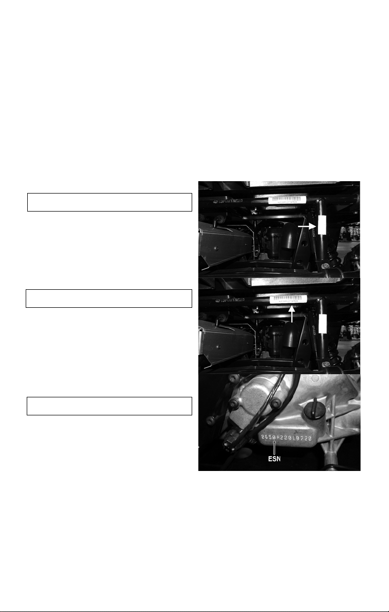
Identification Numbers Record
This vehicle has three identification numbers: Model Number, Serial Number, and
Engine Serial Number (ESN).
These numbers are required by the dealer to complete warranty claims properly. No
warranty will be allowed by Toro if the numbers are removed or mutilated in any way.
Always provide the name, Model Number, Serial Number, and ESN when contacting
an authorized Toro ROV dealer for parts, service, accessories, or warranty. If a complete engine must be replaced, ask the dealer to notify Toro for correct registration
information.
Record the Model Number, Serial Number, and ESN in the spaces provided to assist
you in ordering parts from your authorized Toro ROV dealer or for reference in case
this vehicle is stolen.
1. MODEL NUMBER:
The Model Number is located at the rear
of the vehicle on the verticle frame tube.
2. SERIAL NUMBER:
The Serial Number is located on the frame
support tube under the cargo box facing
the rear of the vehicle.
3. ENGINE SERIAL
NUMBER (ESN):
The ESN is located on the left-side of the
engine crankcase near the bottom of the
crankcase.
Page 68

Vehicle Capacity: 3 seat models, 1 Operator, 2 Passengers with seat belts
©201 6 Toro Company
Form No. 3406-713 Rev. A
 Loading...