

Page 1

FormNo.3372-647RevE
G004222
TX525CompactUtilityLoader
ModelNo.22323—SerialNo.312000001andUp
ModelNo.22324—SerialNo.312000001andUp
Registeratwww.T oro.com.
OriginalInstructions(EN)
*3372-647*E
Page 2
ThisproductcomplieswithallrelevantEuropeandirectives,
fordetailspleaseseetheseparateproductspecicDeclaration
ofConformity(DOC)sheet.
YoumaycontactTorodirectlyatwww .Toro.comforproduct
andaccessoryinformation,helpndingadealer,ortoregister
yourproduct.
WARNING
CALIFORNIA
Proposition65Warning
Thisproductcontainsachemicalorchemicals
knowntotheStateofCaliforniatocausecancer,
birthdefects,orreproductiveharm.
Theengineexhaustfromthisproduct
containschemicalsknowntotheStateof
Californiatocausecancer,birthdefects,
orotherreproductiveharm.
Becauseinsomeareastherearelocal,state,orfederal
regulationsrequiringthatasparkarresterbeusedonthe
engineofthismachine,asparkarresterisavailableas
anoption.Ifyourequireasparkarrester,contactyour
AuthorizedToroServiceDealer.
GenuineTorosparkarrestersareapprovedbytheUSDA
ForestryService.
Important:ItisaviolationofCaliforniaPublic
ResourceCodeSection4442touseoroperatetheengine
onanyforest-covered,brush-covered,orgrass-covered
landwithoutasparkarrestermufermaintainedin
workingorder,ortheengineconstricted,equipped,and
maintainedforthepreventionofre.Otherstatesor
federalareasmayhavesimilarlaws.
Theenclosed
informationregardingtheUSEnvironmentalProtection
Agency(EPA)andtheCaliforniaEmissionControl
Regulationofemissionsystems,maintenance,and
warranty.Replacementsmaybeorderedthroughthe
enginemanufacturer.
Engine Owner's Man ual
issuppliedfor
Wheneveryouneedservice,genuineToroparts,oradditional
information,contactanAuthorizedServiceDealerorToro
CustomerServiceandhavethemodelandserialnumbersof
yourproductready .
Figure1identiesthelocationofthe
modelandserialnumbersontheproduct.Writethenumbers
inthespaceprovided.
Figure1
1.Modelandserialnumberlocation
ModelNo.
SerialNo.
Thismanualidentiespotentialhazardsandhassafety
messagesidentiedbythesafetyalertsymbol(Figure2),
whichsignalsahazardthatmaycauseseriousinjuryordeath
ifyoudonotfollowtherecommendedprecautions.
Introduction
Thismachineisacompactutilityloaderintendedforusein
variousearthandmaterialsmovingactivitiesforlandscaping
andconstructionwork.Itisdesignedtooperateawidevariety
ofattachmentseachofwhichperformaspecializedfunction.
Readthisinformationcarefullytolearnhowtooperateand
maintainyourproductproperlyandtoavoidinjuryand
productdamage.Youareresponsibleforoperatingthe
productproperlyandsafely .
©2013—TheToro®Company
8111LyndaleAvenueSouth
Bloomington,MN55420
Figure2
1.Safetyalertsymbol
Thismanualuses2otherwordstohighlightinformation.
Importantcallsattentiontospecialmechanicalinformation
andNoteemphasizesgeneralinformationworthyofspecial
attention.
Contactusatwww.T oro.com.
2
PrintedintheUSA.
AllRightsReserved
Page 3

Contents
Introduction..................................................................2
Safety...........................................................................4
SafeOperatingPractices...........................................4
SoundPressureLevel...............................................6
SoundPower..........................................................6
VibrationLevel.......................................................6
StabilityData..........................................................7
SlopeIndicator.......................................................8
SafetyandInstructionalDecals.................................9
ProductOverview.........................................................13
Controls...............................................................13
Specications........................................................16
Attachments/Accessories........................................16
Operation....................................................................17
AddingFuel...........................................................17
FillingtheFuelTank...............................................17
CheckingtheEngineOilLevel.................................18
CheckingtheHydraulicFluidLevel...........................19
Checking,Adding,andBleedingtheEngine
Coolant.............................................................20
BleedingtheFuelSystem.........................................21
StartingandStoppingtheEngine..............................21
StoppingtheTractionUnit......................................22
MovingaNon-functioningTractionUnit...................22
UsingtheCylinderLock..........................................22
UsingAttachments.................................................23
SecuringtheTractionUnitforTransport....................25
LiftingtheTractionUnit..........................................25
Maintenance.................................................................26
RecommendedMaintenanceSchedule(s)......................26
PremaintenanceProcedures........................................27
OpeningtheHood.................................................27
ClosingtheHood...................................................27
OpeningtheRearAccessCover................................28
ClosingtheRearAccessCover.................................28
RemovingtheSideScreens......................................28
InstallingtheSideScreens........................................28
Lubrication...............................................................29
GreasingtheTractionUnit......................................29
EngineMaintenance..................................................29
ServicingtheAirCleaner.........................................29
ServicingtheEngineOil..........................................30
FuelSystemMaintenance...........................................32
CheckingtheFuelLinesandConnections..................32
DrainingtheFuelFilter/WaterSeparator...................32
ReplacingtheFuelFilterCanisterandIn-line
Filter.................................................................32
DrainingtheFuelTank...........................................33
ElectricalSystemMaintenance....................................33
ServicingtheBattery...............................................33
DriveSystemMaintenance.........................................36
ServicingtheTracks................................................36
CoolingSystemMaintenance......................................39
ServicingtheCoolingSystem...................................39
BeltMaintenance......................................................40
CheckingtheConditionoftheHydraulicPump
Belt...................................................................40
CheckingtheAlternator/FanBeltTension.................40
ControlsSystemMaintenance.....................................40
AdjustingtheTractionControlAlignment.................40
AdjustingtheTractionControlNeutral
Position.............................................................41
AdjustingtheTrackingoftheTractionControl,
FullForwardPosition..........................................41
HydraulicSystemMaintenance....................................42
ReplacingtheHydraulicFilter..................................42
ChangingtheHydraulicFluid...................................43
CheckingtheHydraulicLines...................................44
Cleaning...................................................................45
RemovingDebrisfromtheTractionUnit...................45
CleaningtheChassis...............................................45
Storage........................................................................45
Troubleshooting...........................................................46
Schematics...................................................................49
3
Page 4

Safety
Improperuseormaintenancebytheoperatororowner
canresultininjury.Toreducethepotentialforinjury,
complywiththesesafetyinstructionsandalways
payattentiontothesafetyalertsymbol,which
means:
instruction.Failuretocomplywiththeinstructionmay
resultinpersonalinjuryordeath.
SafeOperatingPractices
Thisproductiscapableofamputatinghandsandfeet.Always
followallsafetyinstructionstoavoidseriousinjuryordeath.
Engineexhaustcontainscarbonmonoxide,an
odorless,deadlypoisonthatcankillyou.
Donotruntheengineindoorsorinanenclosed
area.
Training
•ReadtheOperator'sManualandothertrainingmaterial.If
•Becomefamiliarwiththesafeoperationoftheequipment,
•Alloperatorsandmechanicsshouldbetrained.The
•Neverletchildrenoruntrainedpeopleoperateorservice
•Theowner/usercanpreventandisresponsiblefor
Preparation
•Evaluatetheterraintodeterminewhataccessoriesand
•Wearappropriateclothingincludinghardhat,safety
•Inspecttheareawheretheequipmentistobeusedand
•Useextracarewhenhandlingfuels.Theyareammable
Caution
,
W ar ning
,or
Danger
—personalsafety
WARNING
theoperator(s)ormechanic(s)cannotreadEnglish,itis
theowner'sresponsibilitytoexplainthismaterialtothem.
operatorcontrols,andsafetysigns.
ownerisresponsiblefortrainingtheusers.
theequipment.Localregulationsmayrestricttheageof
theoperator.
accidentsorinjuriesoccurringtohimselforherself,other
peopleorproperty.
attachmentsareneededtoproperlyandsafelyperform
thejob.Onlyuseaccessoriesandattachmentsapproved
bythemanufacturer.
glasses,longpants,safetyshoes,andhearingprotection.
Longhair,looseclothingorjewelrymaygettangledin
movingparts.
removeallobjectssuchasrocks,toys,andwirewhichcan
bethrownbythemachine.
andvaporsareexplosive.
–Useonlyanapprovedcontainer
–Neverremovethefuelcaporaddfuelwiththeengine
running.Allowtheenginetocoolbeforerefueling.
Donotsmoke.
–Neverrefuelordrainthemachineindoors.
•Checkthattheoperator'spresencecontrols,safety
switches,andshieldsareattachedandfunctioning
properly.Donotoperateunlesstheyarefunctioning
properly.
Operation
•Neverrunanengineinanenclosedarea.
•Onlyoperateingoodlight,keepingawayfromholesand
hiddenhazards.
•Besurealldrivesareinneutralandparkingbrakeis
engagedbeforestartingtheengine.Onlystarttheengine
fromtheoperator'sposition.
•Slowdownanduseextracareonhillsides.Besureto
travelintherecommendeddirectiononhillsides.Turf
conditionscanaffectthemachine'sstability.
•Slowdownandusecautionwhenmakingturnsandwhen
changingdirectionsonslopes.
•Neveroperatewithouttheguardssecurelyinplace.Be
sureallinterlocksareattached,adjusted,andfunctioning
properly.
•Donotchangetheenginegovernorsettingoroverspeed
theengine.
•Stoponlevelground,lowerimplements,disengagethe
auxiliaryhydraulics,engageparkingbrake,shutoffthe
enginebeforeleavingtheoperator'spositionforany
reason.
•Keephandsandfeetawayfrommovingattachments.
•Lookbehindanddownbeforebackinguptobesureof
aclearpath.
•Nevercarrypassengersandkeeppetsandbystanders
away.
•Slowdownandusecautionwhenmakingturnsand
crossingroadsandsidewalks.
•Donotoperatethemachineundertheinuenceof
alcoholordrugs.
•Usecarewhenloadingorunloadingthemachineintoa
trailerortruck.
•Usecarewhenapproachingblindcorners,shrubs,trees,
orotherobjectsthatmayobscurevision.
•Readallattachmentmanuals.
•Ensurethattheareaisclearofotherpeoplebefore
operatingthetractionunit.Stopthetractionunitif
anyoneentersthearea.
•Neverleavearunningtractionunitunattended.Always
lowertheloaderarms,stoptheengine,settheparking
brake,andremovethekeybeforeleaving.
•Donotexceedtheratedoperatingcapacity,asthetraction
unitmaybecomeunstablewhichmayresultinlossof
control.
•Donotcarryaloadwiththearmsraised.Alwayscarry
loadsclosetotheground.
4
Page 5

•Donotover-loadtheattachmentandalwayskeepthe
loadlevelwhenraisingtheloaderarms.Logs,boards,and
otheritemscouldrolldowntheloaderarms,injuringyou.
•Neverjerkthecontrols;useasteadymotion.
•Watchfortrafcwhenoperatingnearorcrossing
roadways.
•Donottouchpartswhichmaybehotfromoperation.
Allowthemtocoolbeforeattemptingtomaintain,adjust,
orservice.
•Checkforoverheadclearances(i.e.branches,doorways,
electricalwires)beforedrivingunderanyobjectsanddo
notcontactthem.
•Ensurethatyouoperatethetractionunitinareaswhere
therearenoobstaclesincloseproximitytotheoperator.
Failuretomaintainadequatedistancefromtrees,walls,
andotherbarriersmayresultininjuryasthetractionunit
backsupduringoperationiftheoperatorisnotattentive
tothesurroundings.Onlyoperatetheunitinareaswhere
thereissufcientclearancefortheoperatortosafely
maneuvertheproduct.
•Beforedigging,havetheareamarkedforunderground
utilities,anddonotdiginmarkedareas.
•Locatethepinchpointareasmarkedonthetractionunit
andattachmentsandkeephandsandfeetawayfrom
theseareas.
•Beforeoperatingthetractionunitwithanattachment,
ensurethattheattachmentisproperlyinstalled.
•Lightningcancausesevereinjuryordeath.Iflightning
isseenorthunderisheardinthearea,donotoperate
themachine;seekshelter.
SlopeOperation
terraincouldoverturnthetractionunit.Tallgrasscan
hideobstacles.
•UseonlyToro-approvedattachments.Attachmentscan
changethestabilityandtheoperatingcharacteristicsof
thetractionunit.Warrantymaybevoidedifusedwith
unapprovedattachments.
•Keepallmovementsonslopesslowandgradual.Donot
makesuddenchangesinspeedordirection.
•Avoidstartingorstoppingonaslope.Ifthetractionunit
losestraction,proceedslowly,straightdowntheslope.
•Avoidturningonslopes.Ifyoumustturn,turnslowly
andkeeptheheavyendofthetractionunituphill.
•Donotoperateneardrop-offs,ditches,orembankments.
Thetractionunitcouldsuddenlyturnoverifatrackgoes
overtheedgeofaclifforditch,orifanedgecavesin.
•Donotoperateonwetgrass.Reducedtractioncould
causesliding.
•Donotparkthetractionunitonahillsideorslope
withoutloweringtheattachmenttotheground,setting
theparkingbrake,andchockingthetracks.
MaintenanceandStorage
•Disengagetheauxiliaryhydraulics,lowertheattachment,
settheparkingbrake,stoptheengine,andremovethe
key.Waitforallmovementtostopbeforeadjusting,
cleaning,orrepairing.
•Cleandebrisfromattachments,drives,mufers,and
enginetohelppreventres.Cleanupoilorfuelspillage.
•Lettheenginecoolbeforestoringanddonotstorenear
ame.
Slopesareamajorfactorrelatedtoloss-of-controland
tip-overaccidents,whichcanresultinsevereinjuryordeath.
Allslopesrequireextracaution.
•Donotoperatethetractionunitonhillsidesor
slopesexceedingtheanglesrecommendedin
StabilityData(page7),andthoseintheattachment
Operator'sManual.SeealsotheSlopeIndicator(page8).
•Operateupanddownslopeswiththeheavyendof
thetractionunituphill.Weightdistributionchanges.
Anemptybucketwillmaketherearofthetractionunit
theheavyend,andafullbucketwillmakethefrontofthe
tractionunittheheavyend.Mostotherattachmentswill
makethefrontoftractionunittheheavyend.
•Raisingtheloaderarmsonaslopewillaffectthestability
ofthemachine.Wheneverpossible,keeptheloaderarms
intheloweredpositionwhenonslopes.
•Removinganattachmentonaslopewillmaketherearof
thetractionunitheavy.Referto
determinewhethertheattachmentcanbesafelyremoved
ontheslope.
StabilityData(page7),to
•Removeobstaclessuchasrocks,treelimbs,etc.fromthe
workarea.Watchforholes,ruts,orbumps,asuneven
•Donotstorefuelnearamesordrainindoors.
•Parkthemachineonlevelground.Neverallowuntrained
personneltoservicethemachine.
•Usejackstandstosupportcomponentswhenrequired.
•Carefullyreleasepressurefromcomponentswithstored
energy.
•Disconnectthebatterybeforemakinganyrepairs.
Disconnectthenegativeterminalrstandthepositive
last.Reconnectpositiverstandnegativelast.
•Keephandsandfeetawayfrommovingparts.Ifpossible,
donotmakeadjustmentswiththeenginerunning.
•Chargebatteriesinanopenwellventilatedarea,away
fromsparkandames.Unplugthechargerbefore
connectingordisconnectingitfromthebattery.Wear
protectiveclothinganduseinsulatedtools.
•Keepallpartsingoodworkingconditionandallhardware
tightened.Replaceallwornordamageddecals.
•Ifanymaintenanceorrepairrequirestheloaderarmsto
beintheraisedposition,securethearmsintheraised
positionwiththehydrauliccylinderlock.
5
Page 6

•Securetheloaderarmvalvewiththeloadervalvelock
anytimeyouneedtostopthemachinewiththeloader
armsraised.
Thesoundpowerlevelwasdeterminedaccordingtothe
proceduresoutlinedinISO6395.
•Keepnutsandboltstight.Keepequipmentingood
condition.
•Nevertamperwithsafetydevices.
•Keepthetractionunitfreeofgrass,leaves,orotherdebris
build-up.Cleanupoilorfuelspillage.Allowthetraction
unittocoolbeforestoring.
•Useextracarewhenhandlingfuels.Theyareammable
andvaporsareexplosive.
–Useonlyanapprovedcontainer.
–Neverremovethefuelcaporaddfuelwhenthe
engineisrunning.Allowtheenginetocoolbefore
refueling.Donotsmokenearammablesubstances.
–Neverrefuelthetractionunitindoors.
–Neverstorethetractionunitorfuelcontainerinside
wherethereisanopename,suchasnearawater
heaterorfurnace.
–Neverllacontainerwhileitisinsideavehicle,trunk,
pick-upbed,oranysurfaceotherthantheground.
–Keepcontainernozzleincontactwiththetankduring
lling.
VibrationLevel
Measuredvibrationlevelforrighthand=1.5m/s
Measuredvibrationlevelforlefthand=1.3m/s
UncertaintyValue(K)=0.8m/s
Measuredvaluesweredeterminedaccordingtotheprocedures
outlinedinENISO20643.
2
2
2
•Stopandinspecttheequipmentifyoustrikeanobject.
Makeanynecessaryrepairsbeforerestarting.
•UseonlygenuineTororeplacementpartstoensurethat
originalstandardsaremaintained.
•Batteryacidispoisonousandcancauseburns.Avoid
contactwithskin,eyes,andclothing.Protectyourface,
eyes,andclothingwhenworkingwithabattery.
•Batterygasescanexplode.Keepcigarettes,sparksand
amesawayfromthebattery.
•Keepyourbodyandhandsawayfrompinholeleaks
ornozzlesthatejecthighpressurehydraulicuid.Use
cardboardorpapertondhydraulicleaks;neveruse
yourhands.Hydraulicuidescapingunderpressurecan
penetrateskinandcauseinjuryrequiringsurgerywithina
fewhoursbyaqualiedsurgeonorgangrenemayresult.
SoundPressureLevel
Thisunithasasoundpressurelevelattheoperator’searof93
dBA,whichincludesanUncertaintyValue(K)of1dBA.
Soundpressurelevelwasdeterminedaccordingtothe
proceduresoutlinedinEN11201.
SoundPower
Thisunithasaguaranteedsoundpowerlevelof101dBA,
whichincludesanUncertaintyValue(K)of1dBA.
6
Page 7
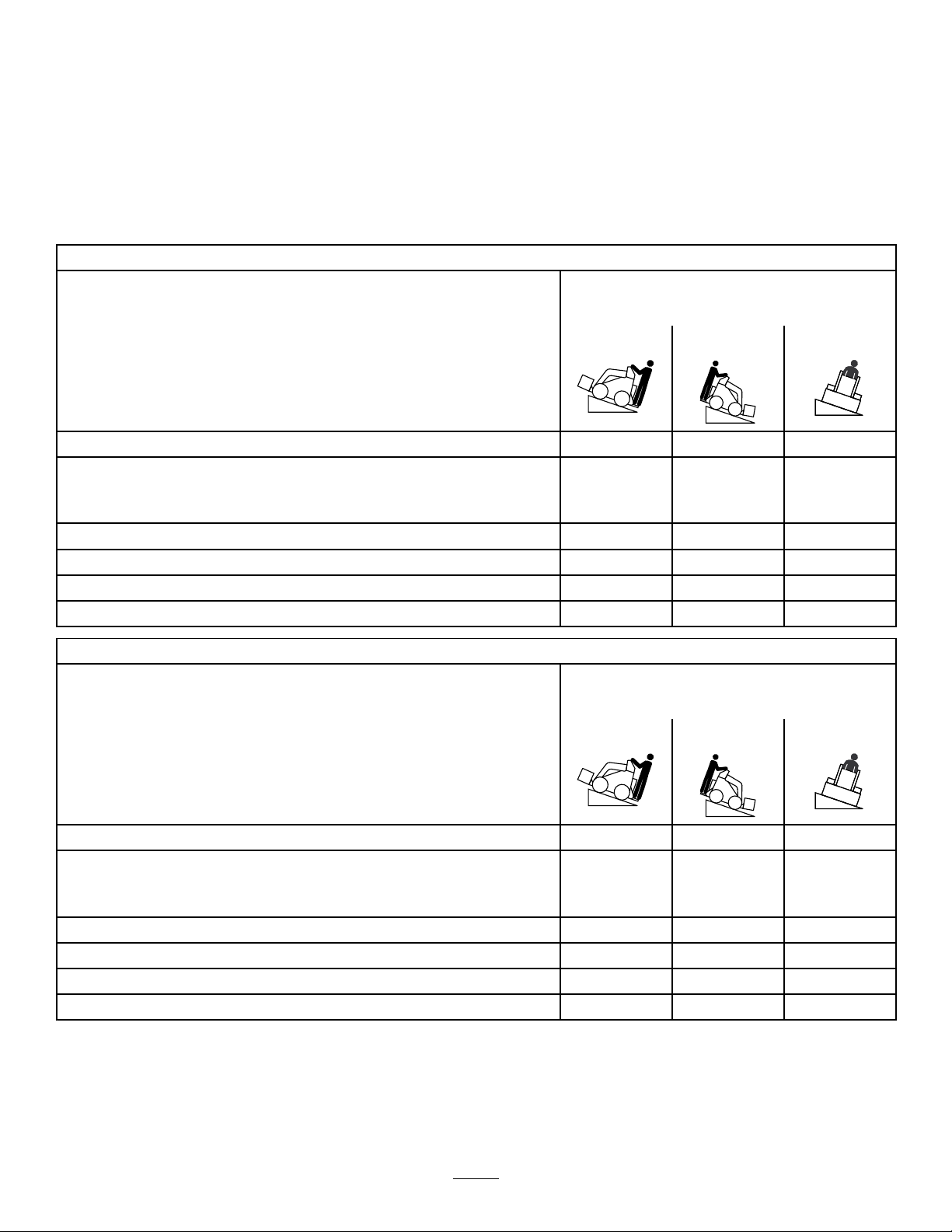
StabilityData
Thefollowingtableslistthemaximumsloperecommendedforthetractionunitinthepositionslistedinthetables.Slopesover
thelisteddegreemaycausethetractionunittobecomeunstable.Thedatainthetablesassumethattheloaderarmsarefully
lowered;raisedarmsmayaffectthestability .
Ineachattachmentmanualisasetofthreestabilityratings,oneforeachhillposition.Todeterminethemaximumslopeyou
cantraversewiththeattachmentinstalled,ndthedegreeofslopethatcorrespondstothestabilityratingsoftheattachment.
Example:IftheattachmentinstalledonaTXmodel22323tractionunithasaFrontUphillratingofB,aRearUphillratingof
D,andaSideUphillratingofC,thenyoucoulddriveforwardupa19°slope,rearwardupa12°slope,orsidewaysona14°
slope,aslistedinthefollowingtable.
Model22323
MaximumRecommendedSlopewhen
Operatingwith:
FrontUphillRearUphill
Conguration
Tractionunitwithoutattachment
Tractionunitwithanattachmentratedwithoneofthefollowingstabilityratings
foreachslopeposition:*
A
B
C16°15°14°
D
E
Model22324
11°21°19°
25°25°20°
19°19°18°
10°12°9°
5°5°5°
MaximumRecommendedSlopewhen
Operatingwith:
FrontUphillRearUphill
SideUphill
SideUphill
Conguration
Tractionunitwithoutattachment
Tractionunitwithanattachmentratedwithoneofthefollowingstabilityratings
foreachslopeposition:*
A
B
C18°16°14°
D
E
12°19°21°
25°25°23°
22°22°20°
10°10°10°
5°5°5°
7
Page 8
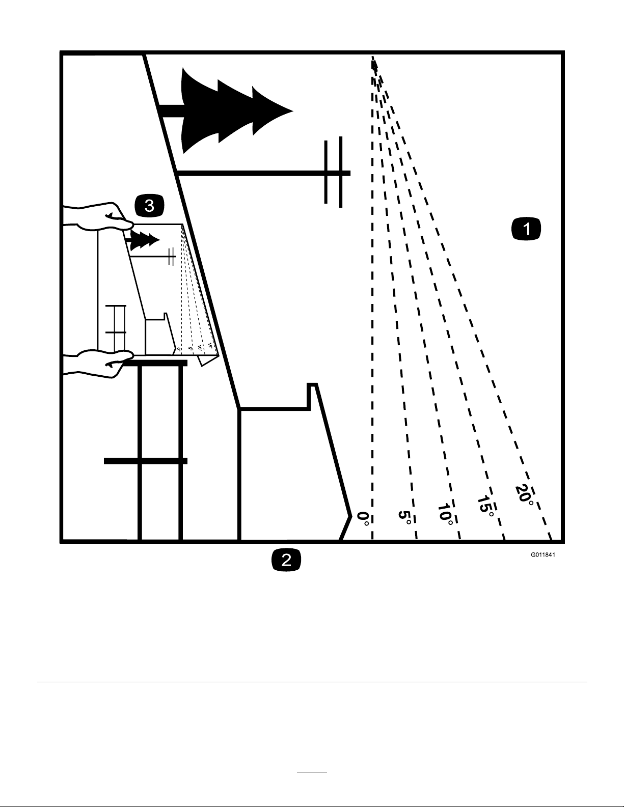
SlopeIndicator
G011841
Figure3
Thispagemaybecopiedforpersonaluse.
1.Todeterminethemaximumslopeyoucansafelyoperatethemachineon,refertotheStabilityDatasection.Usetheslope
indicatortodeterminethedegreeofslopeofhillsbeforeoperating.Donotoperatethismachineonaslopegreaterthanthat
speciedintheStabilityDatasection.Foldalongtheappropriatelinetomatchtherecommendedslope.
2.Alignthisedgewithaverticalsurface,atree,building,fencepole,etc.
3.Exampleofhowtocompareslopewithfoldededge.
8
Page 9

SafetyandInstructionalDecals
Safetydecalsandinstructionsareeasilyvisibletotheoperatorandarelocatednearanyareaofpotential
danger.Replaceanydecalthatisdamagedorlost.
93-6681
1.Cutting/dismemberment—hazard,fan-stayawayfrom
movingparts.
93-9084
100-4650
1.Crushinghazardofhand—keepbystandersasafedistance
fromthemachine.
2.Crushinghazardoffoot—keepbystandersasafedistance
fromthemachine.
1.Liftpoint
2.Tie-downpoint
93-6686
1.Hydraulicoil
2.ReadtheOperator'sManual.
93-7814
1.Entanglementhazard,belt—stayawayfrommovingparts;
keepallguardsandshieldsinplace.
100-8821
1.Crushinghazardandcuttinghazardofhand—stayasafe
distancefromthefrontofthetractionunitwhentheloader
armsareraised.
100-8822
1.Warning—donotcarrypassengers.
114-9600
1.ReadtheOperator'sManual.
9
Page 10
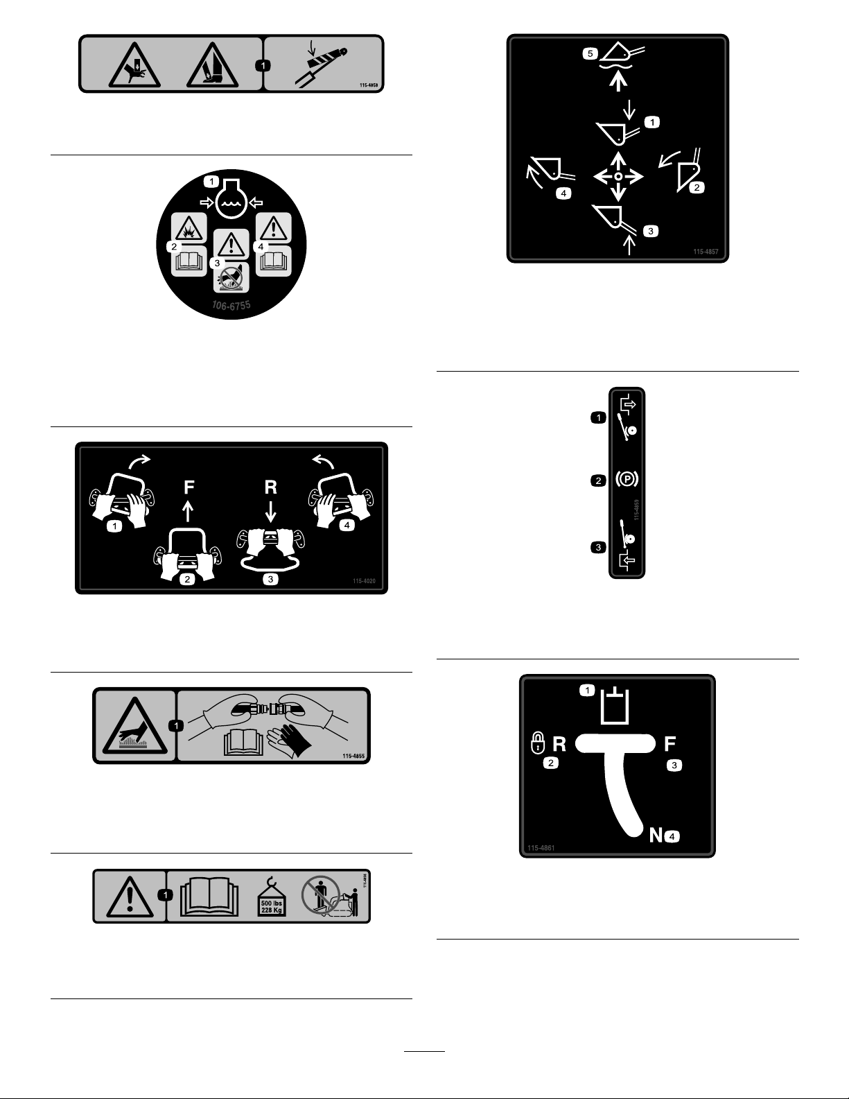
115-4858
1.Crushinghazardofhandsorfeet—installthecylinderlock.
115-4857
106-6755
1.Enginecoolantunder
pressure.
2.Explosionhazard—read
theOperator'sManual.
115-4020
1.Turnright3.Reverse
2.Forward
3.Warning—donottouchthe
hotsurface.
4.Warning—readthe
Operator'sManual.
4.Turnleft
1.Lowertheloaderarms.
2.Dumpthebucket.5.Floatthebucketonthe
3.Raisetheloaderarms.
4.Curlthebucket.
ground.
115-4859
1.Disengaged3.Engaged
2.Parkingbrake
115-4855
1.Hotsurface/burnhazard—wearprotectivegloveswhen
handlingthehydrauliccouplersandreadtheOperator's
Manualforinformationonhandlinghydrauliccomponents.
115-4856
1.Warning—readtheOperator'sManual;maximumload
ratingof500lb(228Kg);noriders.
115-4861
1.Auxiliaryhydraulics3.Forward
2.Lockedreverse(detent)4.Neutral(off)
10
Page 11
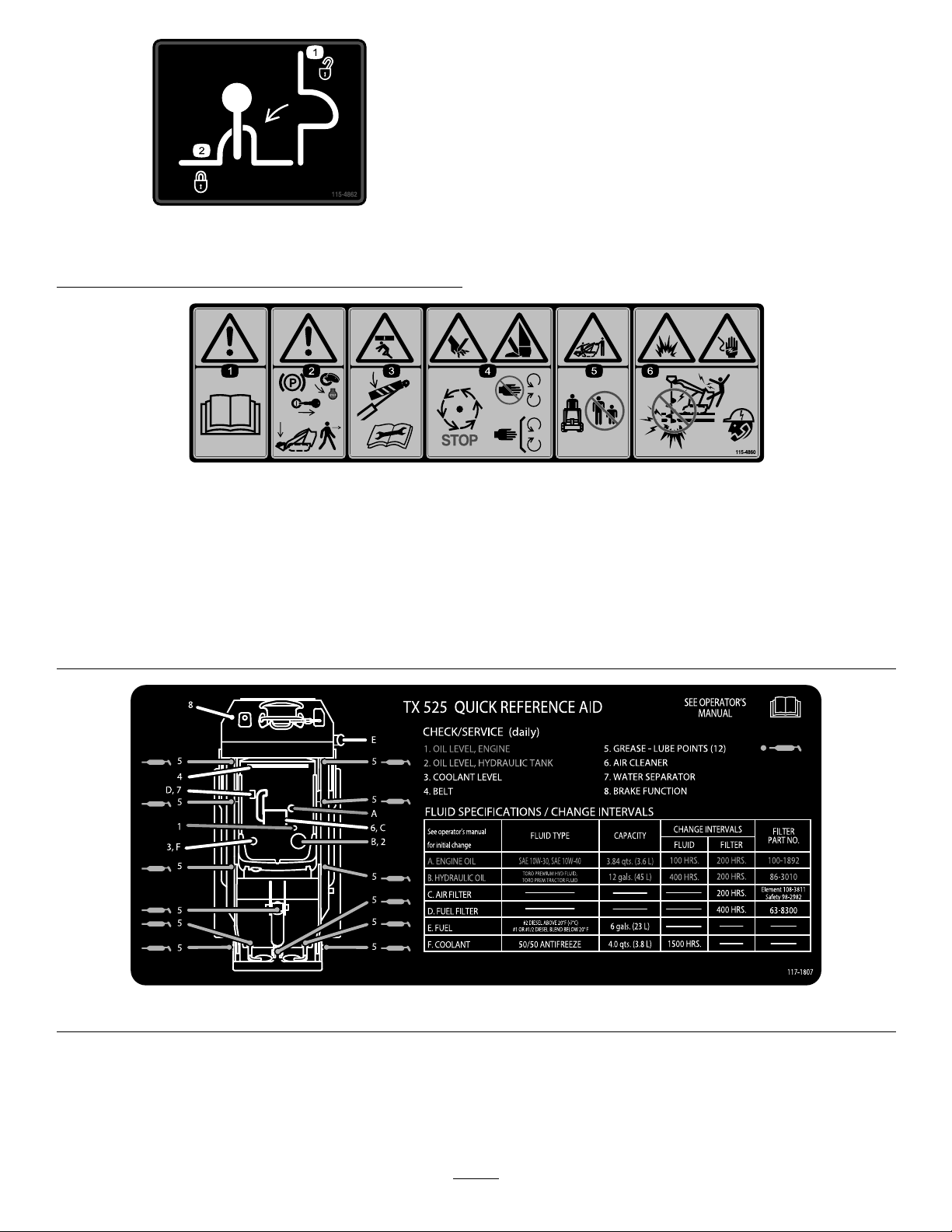
115-4862
1.Loadervalvelock,
unlocked
2.Loadervalvelock,locked
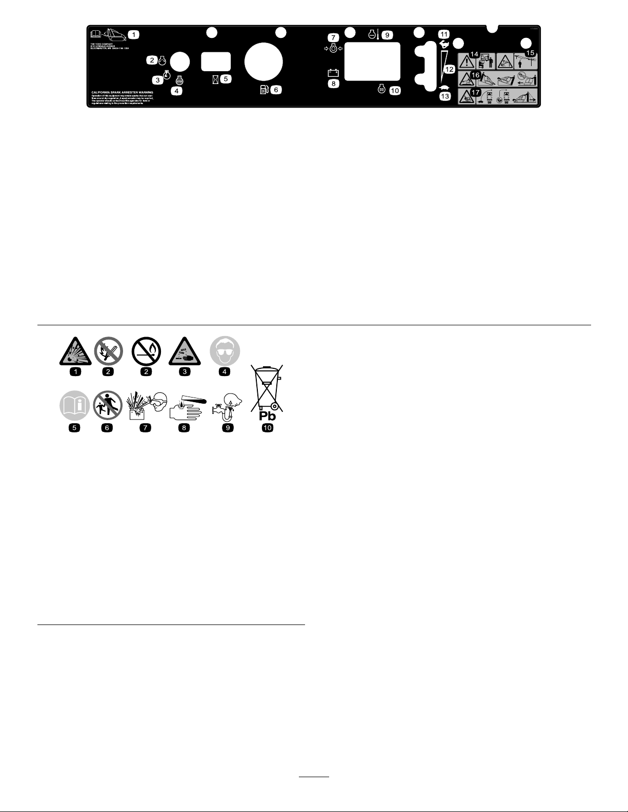
115-4860
1.Warning—readtheOperator'sManual.
2.Warning—settheparkingbrake,stoptheengine,removetheignitionkeyandlowertheloaderarmsbeforeleavingthemachine.
3.Crushinghazard—installthecylinderlockandreadtheinstructionsbeforeservicingorperformingmaintenance.
4.Cuttinghazardofhandsorfeet—waitforallmovingpartstostop;stayawayfrommovingparts;keepallguardsandshieldsin
place.
5.Crushing/dismembermenthazardofbystanders—keepbystandersasafedistancefromthemachine.
6.Explosionandelectricshockhazard—donotdiginareaswithburiedgasorelectricallines;contactlocalpowerorganizations
beforedigging.
117–1807
11
Page 12
117–9905
1.Operator'sManuallocation
2.Engine—start7.Engineoilpressure
3.Engine—run8.Battery
4.Engine—stop9.Enginetemperature14.Warning—donotoperate
5.Hourmeter
6.Fuelgauge—diesel1 1.Fast16.Tippinghazard—movethe
12.Continuousvariablesetting
13.Slow
thismachineunlessyou
aretrained.
10.Glowplug
15.Electricshockhazard,
overheadpowerlines—stay
awayfromoverheadpower
lines.
tractionunitwiththeheavy
enduphill;donottravel
withtheloaderarmsraised.
17.Tippinghazard—slowthe
tractionunitwhenturning,
donottravelfastwhen
turning,lookbehindand
downwhenreversing.
BatterySymbols
Someorallofthesesymbolsareonyourbattery
1.Explosionhazard
2.Nore,opename,or
smoking.
3.Causticliquid/chemical
burnhazard
4.Weareyeprotection9.Flusheyesimmediately
5.ReadtheOperator's
Manual.
6.Keepbystandersasafe
7.Weareyeprotection;
8.Batteryacidcancause
10.Containslead;donot
distancefromthebattery .
explosivegasescan
causeblindnessandother
injuries
blindnessorsevereburns.
withwaterandgetmedical
helpfast.
discard.
12
Page 13
ProductOverview
12
G017858
1
2
3
4
5
6 7
8
12
11
109
g013016
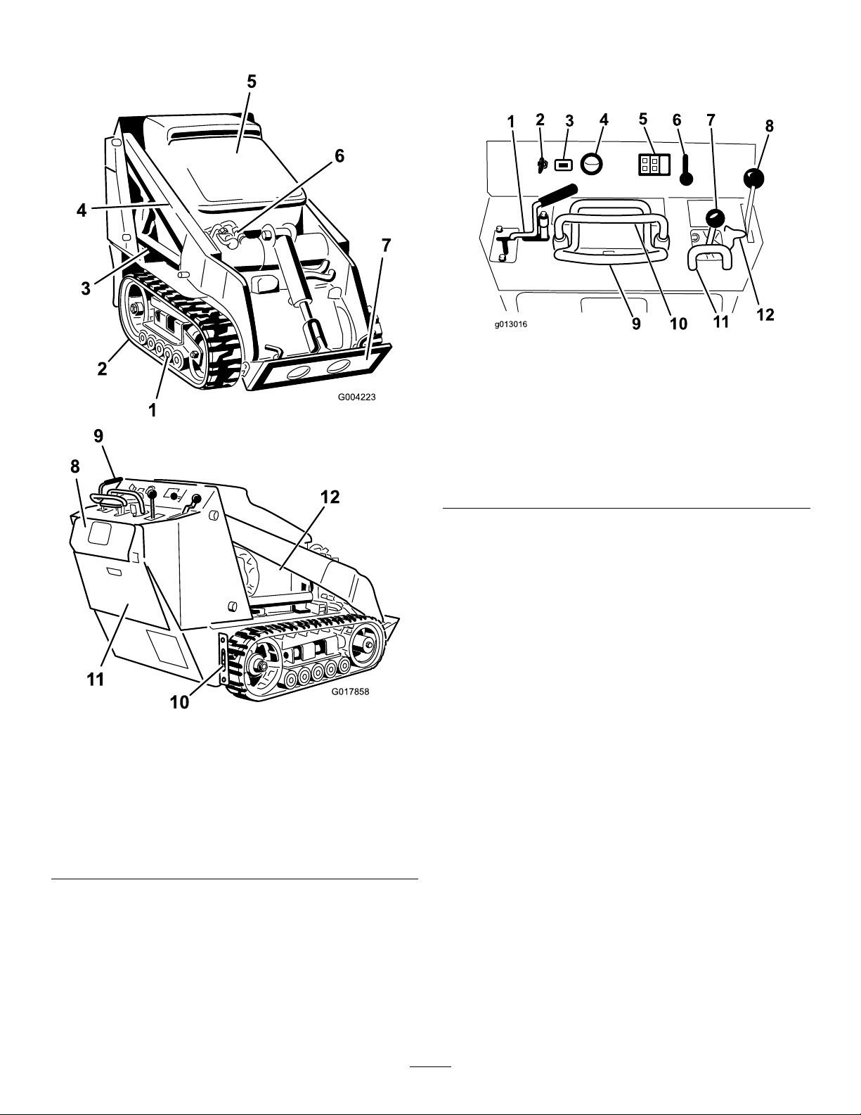
Controls
Becomefamiliarwithallthecontrols(Figure5)beforeyou
starttheengineandoperatethetractionunit.
Figure5
Figure4
1.Roadwheels7.Mountplate
2.Track
3.Liftcylinder9.Controlpanel
4.Loaderarms
5.Hood11.Rearaccesscover
6.Auxiliaryhydraulic
couplers
8.Reversesafetyplate
10.Tie-down/liftloop
12.Sidepanelscreen
1.Auxiliaryhydraulicslever
2.Keyswitch8.Parkingbrakelever
3.Hourmeter9.Tractioncontrol
4.Fuelgauge
5.Indicatorlightsandglow
plugswitch
6.Throttlelever12.Loadervalvelock
7.Loaderarm/attachmenttilt
lever
10.Referencebar
11.Loadercontrolreference
bar
KeySwitch
Thekeyswitch,usedtostartandstoptheengine,hasthree
positions:off,run,andstart.
Tostarttheengine,rotatethekeytothestartposition.Release
thekeywhenenginestartsanditwillmoveautomaticallyto
therunposition.
Tostoptheengine,rotatethekeytotheoffposition.
ThrottleLever
Movethecontrolforwardtoincreasetheenginespeedand
rearwardtodecreasespeed.
ReferenceBar
Whendrivingthetractionunit,usethereferencebaras
ahandleandaleveragepointforcontrollingthetraction
controlandtheauxiliaryhydraulicslever.Toensuresmooth,
controlledoperation,donottakebothhandsoffofthe
referencebarwhileoperatingthetractionunit.
13
Page 14
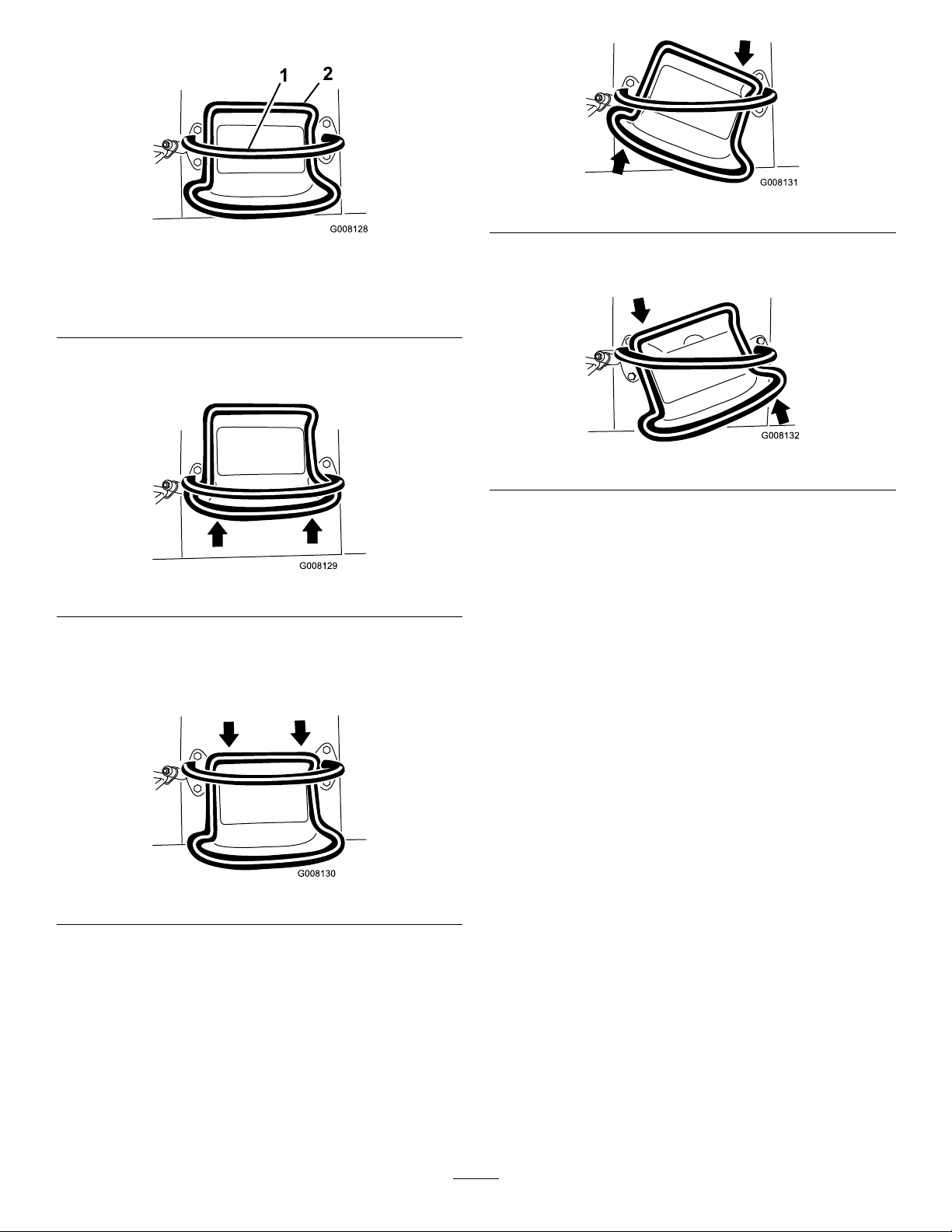
TractionControl
G008131
G008132
Figure9
Figure6
1.Referencebar(doesnotmovetogiveyouareferencepoint
andaxedhandletoholdwhileoperatingthetractionunit)
2.Tractioncontrol(movestocontrolthemachine)
•Tomoveforward,movethetractioncontrolforward
(Figure7).
Figure7
•Tomoverearward,movethetractioncontrolrearward
(Figure8).Whenreversing,lookbehindfor
obstructionsandkeepyourhandsonthereference
bar.
•Toturnleft,rotatethetractioncontrolcounterclockwise
(Figure10).
Figure10
•Tostop,releasethetractioncontrol(Figure6).
Note:Thefartheryoumovethetractioncontrolinany
direction,thefasterthemachinewillmoveinthatdirection.
LoaderArm/AttachmentTiltLever
Totilttheattachmentforward,slowlymovethelevertothe
right(Figure11).
Totilttheattachmentrearward,slowlymovethelevertothe
left(Figure11).
Figure8
•Toturnright,rotatethetractioncontrolclockwise
(Figure9).
Tolowertheloaderarms,slowlymovetheleverforward
(Figure11).
Toraisetheloaderarms,slowlymovetheleverrearward
(Figure11).
Youcanalsopushtheleverfullyforwardintoadetent
position(Figure11)toreleasetheloaderarmssothatthe
attachmentrestsontheground.Thisallowsattachmentssuch
asthelevelerandthehydraulicbladetofollowthecontours
oftheground(i.e.,oat)whengrading.
14
Page 15
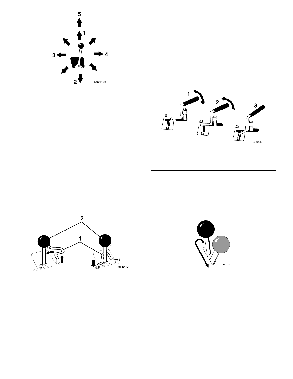
Figure11
AuxiliaryHydraulicsLever
Tooperateahydraulicattachmentintheforwarddirection,
rotatetheauxiliaryhydraulicsleverrearwardandpullitdown
tothereferencebar(Figure13,number1).
Tooperateahydraulicattachmentinreversedirection,rotate
thehydraulicsleverrearward,thenmoveitleftintotheupper
slot(Figure13,number2).
Ifyoureleasetheleverwhileintheforwardposition,thelever
willautomaticallyreturntotheneutralposition(Figure13,
number3).Ifitisinthereverseposition,itwillremainthere
untilyoupullitoutoftheslot.
1.Lowertheloaderarms
2.Raisetheloaderarms
3.Tilttheattachment
rearward
4.Tilttheattachmentforward
5.Detent(Float)position
Bymovingthelevertoanintermediateposition(suchas,
forwardandleft),youcanmovetheloaderarmsandtiltthe
attachmentatthesametime.
LoaderValveLock
Theloadervalvelocksecurestheloaderarm/attachmenttilt
leversothatyoucannotpushitforward.Thishelpstoensure
thatnoonewillaccidentallylowertheloaderarmsduring
maintenance.Securetheloaderarmswiththelockanytime
youneedtostopthemachinewiththeloaderarmsraised.
Tosetthelock,liftuponitsoitclearstheholeinthecontrol
panelandswingittotheleftinfrontoftheloaderarmlever,
pushingitdownintothelockedposition(Figure12).
Figure13
1.Forwardowhydraulics
2.Reverseowhydraulics
3.Neutral
ParkingBrakeLever
Tosettheparkingbrake,pushthebrakeleverforwardandto
theleftandthenpullitrearward(
Note:Thetractionunitmayrollslightlybeforethebrakes
engageinthedrivesprocket.
Figure14).
Figure12
1.Loadervalvelock
2.Loaderarm/attachmenttilt
lever
LoaderControlReferenceBar
Theloadercontrolreferencebarhelpsstabilizeyourhand
whileoperatingtheloaderarm/attachmenttiltlever.
Figure14
Toreleasethebrake,pushtheleverforwardandthenright,
intothenotch.
FuelGauge
Thisgaugemeasurestheamountoffuelinthefueltank.
EngineOilPressureLight
Iftheengineoilpressuregetstoolow ,thislightilluminates
andanaudiblealarmsounds.Ifthishappens,stoptheengine
15
Page 16

immediatelyandchecktheoil.Iflow ,addoiland/orlook
G004350
123
45
forpossibleleaks.
Figure15
1.Engineoilpressurelight4.Batterychargeindicator
2.Enginecoolant
temperaturelight
3.Glowplugswitch
light
5.Glowpluglight
BatteryChargeIndicatorLight
Ifthebatterychargebecomestoolow ,thislightilluminates
andanaudiblealarmsounds.Ifthishappens,stoptheengine
andchargeorreplacethebattery.Checkthetensionofthe
alternatorbelt;refertoyourEngineOperator'sManual.
Specications
Note:Specicationsanddesignaresubjecttochange
withoutnotice.
Model22323
Width
Length
Height
Weight
Operatingcapacity553lb(251Kg)
Tippingcapacity
Wheelbase
Dumpheight(withnarrowbucket)47inches(119cm)
Reach—fullyraised(withnarrowbucket)22inches(55cm)
Heighttohingepin(narrowbucketin
highestposition)
Model22324
Width
Length
Height
Weight
Operatingcapacity553lb(251Kg)
Tippingcapacity
Wheelbase
Dumpheight(withnarrowbucket)47inches(119cm)
Reach—fullyraised(withnarrowbucket)22inches(55cm)
34inches(86cm)
71inches(180cm)
46inches(117cm)
1904lb(864Kg)
1580lb(717Kg)
31.2inches(79cm)
66inches(168cm)
41inches(104cm)
71inches(180cm)
43inches(109cm)
2013lb(913Kg)
1580lb(717Kg)
31.2inches(79cm)
EngineCoolantTemperatureLight
Iftheenginecoolantgetstoohot,thislightilluminatesand
anaudiblealarmsounds.Ifthishappens,stoptheengineand
allowthetractionunittocool.Checkthecoolantlevelwhen
theenginehasfullycooled.
GlowPlugLight
Illuminateswhiletheglowplugsarechargedandwarming
theengine.
GlowPlugSwitch
Pressandholdthisswitchfor10secondstoactivatetheglow
plugsbeforestartingtheengine.
HourMeter
Thehourmeterdisplaysthenumberofhoursofoperation
thathavebeenloggedonthetractionunit.
Heighttohingepin(narrowbucketin
highestposition)
66inches(168cm)
Attachments/Accessories
AselectionofToroapprovedattachmentsandaccessoriesis
availableforusewiththemachinetoenhanceandexpand
itscapabilities.ContactyourAuthorizedServiceDealeror
Distributororgotowww .T oro.comforalistofallapproved
attachmentsandaccessories.
Important:UseonlyToroapprovedattachments.
Otherattachmentsmaycreateanunsafeoperating
environmentordamagethetractionunit.
16
Page 17

Operation
Note:Determinetheleftandrightsidesofthemachine
fromthenormaloperatingposition.
Important:Beforeoperating,checkthefuelandoil
level,andremovedebrisfromthetractionunit.Also,
ensurethattheareaisclearofpeopleanddebris.You
shouldalsoknowandhavemarkedthelocationsofall
utilitylines.
•Monitorseals,hoses,gasketsincontactwithfuelasthey
maybedegradedovertime.
•Fuellterpluggingmaybeexpectedforatimeafter
convertingtobiodieselblendsd.
•Contactyourdistributorifyouwishformoreinformation
onbiodiesel.
FillingtheFuelTank
AddingFuel
Useonlyclean,freshdieselfuelorbiodieselfuelswithlow
(<500ppm)orultralow(<15ppm)sulfurcontent.The
minimumcetaneratingshouldbe40.Purchasefuelin
quantitiesthatcanbeusedwithin180daystoensurefuel
freshness.
Fueltankcapacity:5.85USgallons(22l)
Usesummergradedieselfuel(No.2-D)attemperatures
above20°F(-7°C)andwintergrade(No.1-DorNo.
1-D/2-Dblend)belowthattemperature.Useofwintergrade
fuelatlowertemperaturesprovideslowerashpointand
coldowcharacteristicswhichwilleasestartingandreduce
fuellterplugging.
Useofsummergradefuelabove20°F(-7°C)willcontribute
towardlongerfuelpumplifeandincreasedpowercompared
towintergradefuel.
Important:Donotusekeroseneorgasolineinsteadof
dieselfuel.Failuretoobservethiscautionwilldamage
theengine.
WARNING
Fuelisharmfulorfatalifswallowed.Long-term
exposuretovaporscancauseseriousinjuryand
illness.
•Avoidprolongedbreathingofvapors.
•Keepfaceawayfromnozzleandfueltankor
conditioneropening .
•Keepfuelawayfromeyesandskin.
BiodieselReady
Thismachinecanalsouseabiodieselblendedfuelofup
toB20(20%biodiesel,80%petrodiesel).Thepetrodiesel
portionshouldbeloworultralowsulfur.Observethe
followingprecautions:
•Thebiodieselportionofthefuelmustmeetspecication
ASTMD6751orEN14214.
•TheblendedfuelcompositionshouldmeetASTMD975
orEN590.
•Paintedsurfacesmaybedamagedbybiodieselblends.
•UseB5(biodieselcontentof5%)orlesserblendsincold
weather.
DANGER
Incertainconditions,fuelisextremelyammable
andhighlyexplosive.Areorexplosionfromfuel
canburnyouandothersandcandamageproperty.
•Fillthefueltankoutdoors,inanopenarea,when
theengineiscold.Wipeupanyfuelthatspills.
•Neverllthefueltankinsideanenclosedtrailer.
•Neversmokewhenhandlingfuel,andstayaway
fromanopenameorwherefuelfumesmaybe
ignitedbyaspark.
•Storefuelinanapprovedcontainerandkeepit
outofthereachofchildren.Neverbuymore
thana30-daysupplyoffuel.
•Donotoperatewithoutentireexhaustsystemin
placeandinproperworkingcondition.
DANGER
Incertainconditionsduringfueling,static
electricitycanbereleasedcausingasparkwhich
canignitethefuelvapors.Areorexplosionfrom
fuelcanburnyouandothersandcandamage
property.
•Alwaysplacefuelcontainersonthegroundaway
fromyourvehiclebeforelling.
•Donotllfuelcontainersinsideavehicleoron
atruckortrailerbedbecauseinteriorcarpets
orplastictruckbedlinersmayinsulatethe
containerandslowthelossofanystaticcharge.
•Whenpractical,removeequipmentfromthe
truckortrailerandrefueltheequipmentwithits
wheelsontheground.
•Ifthisisnotpossible,thenrefuelsuch
equipmentonatruckortrailerfromaportable
container,ratherthanfromafueldispenser
nozzle.
•Ifafueldispensernozzlemustbeused,keepthe
nozzleincontactwiththerimofthefueltank
orcontaineropeningatalltimesuntilfuelingis
complete.
17
Page 18

1.Removethefueltankcap(Figure16).
CheckingtheEngineOilLevel
ServiceInterval:Beforeeachuseordaily
1.Parkthetractionunitonalevelsurface,lowerthe
loaderarms,andstoptheengine.
2.Removethekeyandallowtheenginetocool.
3.Openthehood.
Figure16
1.Fueltankcap
2.Fillthetanktoaboutoneinchbelowthetopofthe
tank,notthellerneck,withdieselfuel.
3.Installthefueltankcap.
4.Cleanaroundtheoildipstick(
Figure17
1.Oildipstick2.Oilllercap
Figure17).
5.Pulloutthedipstickandwipethemetalendclean
(Figure17).
6.Slidethedipstickfullyintothedipsticktube(Figure17).
7.Pullthedipstickoutandlookatthemetalend.
8.Iftheoillevelislow(belowthebottomhole),clean
aroundtheoilllercapandremovethecap(
9.Slowlypouronlyenoughoilintothevalvecoverto
raisetheleveltothetopholeonthedipstick.
Important:Donotoverllthecrankcasewithoil
becausetheenginemaybedamaged.
10.Replacethellercapanddipstick.
11.Closethehood.
Figure17).
18
Page 19

CheckingtheHydraulicFluid Level
ServiceInterval:Every25hours
HydraulicTankCapacity:12USgallons(45.4l)
RefertoChangingtheHydraulicFluid(page43)forhydraulic
uidspecications.
Important:Alwaysusethecorrecthydraulicuid.
Unspecieduidswilldamagethehydraulicsystem.
1.Removetheattachment,ifoneisinstalled;referto
RemovinganAttachment.
2.Parkthetractionunitonalevelsurface,lowerthe
loaderarms,andfullyretractthetiltcylinder.
3.Stoptheengine,removethekey ,andallowtheengine
tocool.
Figure19
1.Fillerneck2.Dipstick
4.Openthehood.
5.Cleantheareaaroundthellerneckofthehydraulic
Figure18).
tank(
Figure18
1.Hydraulicllerneckcap
7.Ifthelevelislow,addenoughuidtoraiseittothe
properlevel.
8.Installthecaponthellerneck.
9.Closethehood.
6.Removethecapfromthellerneckandchecktheuid
levelonthedipstick(Figure19).
Theuidlevelshouldbebetweenthemarksonthe
dipstick.
19
Page 20

Checking,Adding,and BleedingtheEngineCoolant
ServiceInterval:Beforeeachuseordaily
Cleandebrisoffofthescreen,oilcooler,andfrontofthe
radiatordailyandmoreoftenifconditionsareextremely
dustyanddirty
Thecoolingsystemislledwitha50/50solutionofwater
andpermanentethyleneglycolantifreeze.Checkthelevel
ofcoolantintheexpansiontankatthebeginningofeach
daybeforestartingtheengine.
DANGER
Iftheenginehasbeenrunning,thepressurized,hot
coolantcanescapeandcausesevereburns.
•Donotremovetheradiatorcapwhentheengine
ishot.Alwaysallowtheenginetocoolatleast
15minutesoruntiltheradiatorcapiscool
enoughtotouchwithoutburningyourhand
beforeremovingtheradiatorcap.
•Donottouchradiatorandsurroundingparts
thatarehot.
•Usearagwhenopeningtheradiatorcap,and
openthecapslowlytoallowsteamtoescape.
DANGER
Rotatingshaftandfancancausepersonalinjury.
•Donotoperatethemachinewithoutthecovers
inplace.
•Keepngers,handsandclothingclearof
rotatingfananddriveshaft.
•Shutofftheegineandremovetheignitionkey
beforeperformingmaintenance.
Figure20
1.Expansiontank
2.Fullmark
2.Ifthecoolantlevelislow,completethefollowing
procedure:
A.Removethecoolantllcap(Figure21).
1.Checkthelevelofcoolantintheexpansiontank
Figure20).
(
Thecoolantlevelshouldbeatorabovethemarkon
thesideofthetank.
Figure21
1.Expansiontank3.Topcoolantbleedvalve
2.Coolantllcapandller
neck
B.Openthefrontandtopcoolantbleedvalves
C.Pourcoolantintothecoolantllerneckuntilthe
D.Closethefrontcoolantbleedvalve(Figure21).
E.Pourcoolantintothecoolantllerneckuntilthe
20
(Figure21).
coolantbeginstocomeoutofthefrontcoolant
bleedvalve(Figure21).
coolantbeginstocomeoutofthetopcoolant
bleedvalve(
Figure21).
4.Frontcoolantbleedvalve
Page 21

F.Closethetopcoolantbleedvalve(Figure21).
G.Pourcoolantintothecoolantllerneckuntilthe
coolantlevelcomesintothellerneck(Figure21).
H.Installthecoolantllcap(Figure21).
I.Addcoolantintotheexpansiontankuntilit
reachestheFulllineonthesideofthetank
Figure21).
(
3.Installtheexpansiontankcap.
BleedingtheFuelSystem
Youmustbleedthefuelsystembeforestartingtheengineif
anyofthefollowingsituationshaveoccurred:
•Initialstartupofanewmachine.
•Enginehasceasedrunningduetolackoffuel.
•Maintenancehasbeenperformeduponfuelsystem
components(e.g.,lterreplaced).
DANGER
Undercertainconditions,dieselfuelandfuel
vaporsarehighlyammableandexplosive.Are
orexplosionfromfuelcanburnyouandothersand
cancausepropertydamage.
•Useafunnelandllthefueltankoutdoors,in
anopenarea,whentheengineisoffandiscold.
Wipeupanyfuelthatspills.
•Donotllthefueltankcompletelyfull.Add
fueltothefueltankuntilthelevelis1/4to1/2
in.(6to13mm)belowthebottomoftheller
neck.Thisemptyspaceinthetankallowsthe
fueltoexpand.
•Neversmokewhenhandlingfuel,andstayaway
fromanopenameorwherefuelfumesmaybe
ignitedbyaspark.
•Storefuelinaclean,safety-approvedcontainer
andkeepthecapinplace.
1.Ensurethatthefueltankisatleasthalffull.
2.Openthehood.
3.Opentheairbleedscrewonthefuelinjectionpump
(
Figure22).
Figure22
1.Fuelinjectionpumpbleedscrew
4.TurnthekeyintheignitionswitchtotheOnposition.
Theelectricfuelpumpwillbeginoperation,thereby
forcingairoutaroundtheairbleedscrew .Leavethe
keyintheOnpositionuntilasolidstreamoffuelows
outaroundthescrew .
5.TightenthescrewandturnthekeytotheOffposition.
Note:Normally,theengineshouldstartaftertheabove
bleedingproceduresarefollowed.However,ifenginedoes
notstart,airmaybetrappedbetweeninjectionpumpand
injectors;contactyourAuthorizedServiceDealer.
StartingandStoppingthe Engine
StartingtheEngine
1.Ensurethattheauxiliaryhydraulicsleverisinneutral.
2.Movethethrottlelevermidwaybetweenslow(turtle)
andfast(rabbit)positions.
3.TurntheignitionkeytotheRunposition.
4.Presstheglowplugswitchandholditfor10seconds.
5.TurntheignitionkeytotheStartposition.Whenthe
enginesstarts,releasethekey.
Important:Donotengagethestarterformore
than10secondsatatime.Iftheenginefailsto
start,allowa30secondcool-downperiodbetween
attempts.Failuretofollowtheseinstructionscan
burnoutthestartermotor.
6.Movethethrottlelevertodesiredsetting.
Important:Iftheengineisrunathighspeeds
whenthehydraulicsystemiscold(i.e.,whenthe
ambientairtemperatureisnearfreezingorlower),
21
Page 22

hydraulicsystemdamagecouldoccur.When
startingtheengineincoldconditions,allowthe
enginetoruninthemiddlethrottlepositionfor
2to5minutesbeforemovingthethrottletofast
(rabbit).
Note:Ifoutdoortemperatureisbelowfreezing,store
thetractionunitinagaragetokeepitwarmerandaid
instarting.
StoppingtheEngine
1.Movethethrottlelevertotheslow(turtle)position.
2.Lowertheloaderarmstotheground.
3.Turntheignitionkeyoff.
Note:Iftheenginehasbeenworkinghardorishot,
letitidleforaminutebeforeturningtheignitionkey
off.Thishelpscooltheenginebeforeitisstopped.In
anemergency,theenginemaybestoppedimmediately.
Figure23
1.Lefttowvalve(righttrack)2.Righttowvalve(lefttrack)
StoppingtheTractionUnit
Tostopthetractionunit,releasethetractioncontrol,move
thethrottlelevertoslow(turtle),lowerloaderarmstothe
ground,andstoptheengine.Settheparkingbrakeand
removethekey .
CAUTION
Achildoruntrainedbystandercouldattemptto
operatethetractionunitandbeinjured.
Removethekeyfromtheswitchwhenleavingthe
tractionunit,evenifjustforafewseconds.
MovingaNon-functioning TractionUnit
Important:Donottoworpullthetractionunitwithout
rstopeningthetowvalves,orthehydraulicsystemwill
bedamaged.
1.Stoptheengine.
2.Opentherearaccesscover.
4.Towthetractionunitasrequired.
5.Whenthetractionunithasbeenrepaired,closethetow
valvesbeforeoperatingit.
UsingtheCylinderLock
WARNING
Theloaderarmsmaylowerwhenintheraised
positioncrushinganyoneunderthem.
Installthecylinderlockbeforeperforming
maintenancethatrequiresraisedloaderarms.
InstallingtheCylinderLock
1.Removetheattachment.
2.Raisetheloaderarmstothefullyraisedposition.
3.Stoptheengine.
4.Removethelynchpinsecuringthecylinderlocktothe
loaderarm(
Figure24).
3.Usingawrench,turnthetowvalvesonthehydraulic
pumpstwicecounter-clockwise(
Figure23).
22
Page 23

G004182
3
2
1
Figure24
Important:Beforeinstallingtheattachment,ensure
thatthemountplatesarefreeofanydirtordebrisand
thatthepinsrotatefreely.Ifthepinsdonotrotatefreely,
greasethem.
1.Positiontheattachmentonalevelsurfacewithenough
spacebehindittoaccommodatethetractionunit.
2.Starttheengine.
3.Tilttheattachmentmountplateforward.
4.Positionmountplateintotheupperlipofthe
attachmentreceiverplate(Figure25).
1.Cylinderlock
2.Liftcylinder
5.Lowerthecylinderlockoverthecylinderrodand
secureitwiththelynchpin(Figure24).
6.Slowlylowertheloaderarmsuntilcylinderlock
contactsthecylinderbodyandrodend.
3.Lynchpin
Removing/StoringtheCylinderLock
Important:Ensurethatthecylinderlockisremoved
fromtherodandfullysecuredinthestorageposition
beforeoperatingthetractionunit.
1.Starttheengine.
2.Raisetheloaderarmstothefullyraisedposition.
3.Stoptheengine.
4.Removethelynchpinsecuringthecylinderlock.
5.Rotatethecylinderlockuptotheloaderarmand
secureitwiththelynchpin.
6.Lowertheloaderarms.
UsingAttachments
Important:Ifyouareusinganattachmentwithaserial
numberof200999999orearlier,themanualforthe
attachmentmaycontaininformationspecictotheuse
oftheattachmentwithothertractionunitsmodels,such
assettingsfortheowdividercontrolandspeedselector
leverandtheuseofacounterweightonthetractionunit.
ThesesystemsarebuiltintotheTX,andyoushould
ignoreanyreferencestothem.
Figure25
1.Mountplate2.Receiverplate
5.Raisetheloaderarmswhiletiltingbackthemountplate
atthesametime.
Important:Theattachmentshouldberaised
enoughtocleartheground,andthemountplate
shouldbetiltedallthewayback.
6.Stoptheengine.
7.Engagethequickattachpins,ensuringthattheyare
fullyseatedinthemountplate(
Important:Ifthepinsdonotrotatetothe
engagedposition,themountplateisnotfully
alignedwiththeholesintheattachmentreceiver
plate.Checkthereceiverplateandcleanitif
necessary.
Figure26).
InstallinganAttachment
Important:UseonlyToro-approvedattachments.
Attachmentscanchangethestabilityandtheoperating
characteristicsofthetractionunit.Thewarrantyofthe
tractionunitmaybevoidedifusedwithunapproved
attachments.
23
Page 24

1.Quickattachpins(shown
inengagedposition)
2.Disengagedposition
Figure26
3.Engagedposition
Note:Whenyouconnecttheattachmentmale
connectorrst,youwillrelieveanypressurebuiltupin
theattachment.
WARNING
Hydraulicuidescapingunderpressurecan
penetrateskinandcauseinjury.Fluidinjected
intotheskinmustbesurgicallyremoved
withinafewhoursbyadoctorfamiliarwith
thisformofinjuryorgangrenemayresult.
•Keepyourbodyandhandsawayfrom
pinholeleaksornozzlesthatejecthigh
pressurehydraulicuid.
•Usecardboardorpapertondhydraulic
leaks,neveruseyourhands.
CAUTION
Hydrauliccouplers,hydrauliclines/valves,
andhydraulicuidmaybehot.Ifyoucontact
hotcomponentsyoumaybeburned.
•Weargloveswhenoperatingthehydraulic
couplers.
•Allowthetractionunittocoolbefore
touchinghydrauliccomponents.
WARNING
Ifyoudonotfullyseatthequickattachpins
throughtheattachmentmountplate,the
attachmentcouldfalloffofthetractionunit,
crushingyouorbystanders.
Ensurethatyourquickattachpinsarefully
seatedintheattachmentmountplate.
ConnectingtheHydraulicHoses
Iftheattachmentrequireshydraulicsforoperation,connect
thehydraulichosesasfollows:
1.Stoptheengine.
2.Movetheauxiliaryhydraulicsleverforward,backward,
andbacktoneutraltorelievepressureatthehydraulic
couplers.
3.Movetheauxiliaryhydraulicsleverintothereverse
position.
4.Removetheprotectivecoversfromthehydraulic
couplersonthetractionunit.
5.Ensurethatallforeignmatteriscleanedfromthe
hydraulicconnectors.
6.Pushtheattachmentmaleconnectorintothefemale
connectoronthetractionunit.
•Donottouchhydraulicuidspills.
7.Pushtheattachmentfemaleconnectorintothemale
connectoronthetractionunit.
8.Conrmthattheconnectionissecurebypullingon
thehoses.
9.Movetheauxiliaryhydraulicslevertoneutral.
RemovinganAttachment
1.Lowertheattachmenttotheground.
2.Stoptheengine.
3.Disengagethequickattachpinsbyturningthemto
theoutside.
4.Iftheattachmentuseshydraulics,movetheauxiliary
hydraulicsleverforward,backward,andbacktoneutral
torelievepressureatthehydrauliccouplers.
5.Iftheattachmentuseshydraulics,slidethecollarback
onthehydrauliccouplersanddisconnectthem.
Important:Connecttheattachment
hosestogethertopreventhydraulicsystem
contaminationduringstorage.
6.Installtheprotectivecoversontothehydrauliccouplers
onthetractionunit.
7.Starttheengine,tiltthemountplateforward,andback
thetractionunitawayfromtheattachment.
24
Page 25

SecuringtheTractionUnitfor Transport
Whentransportingthetractionunitonatrailer,alwaysuse
thefollowingprocedure:
Important:Donotoperateordrivethetractionunit
onroadways.
1.Lowertheloaderarms.
2.Stoptheengine.
3.Securethetractionunittothetrailerwithchainsor
strapsusingthetie-down/liftloops(Figure4)tosecure
therearofthetractionunitandtheloaderarms/mount
platetosecurethefrontofthetractionunit.
LiftingtheTractionUnit
Youcanliftthetractionunitusingthetie-down/liftloops
asliftpoints(Figure4).
25
Page 26

Maintenance
Note:Determinetheleftandrightsidesofthemachinefromthenormaloperatingposition.
RecommendedMaintenanceSchedule(s)
MaintenanceService
Interval
Aftertherst8hours
Aftertherst50hours
Beforeeachuseordaily
Every25hours
Every100hours
MaintenanceProcedure
•Replacethehydrauliclter.
•Changetheengineoilandlter.
•Checkandadjustthetracktension.
•Checktheengineoillevel.
•Checkthecoolingsystem.
•Greasethetractionunit.(Greaseimmediatelyaftereverywashing.)
•Checktheairlterserviceindicator.
•Drainwaterandothercontaminantsfromthefuellter/waterseparator.
•Cleanthetracks.
•Checkthetracksforexcessivewear(Ifthetracksareworn,replacethem.)
•Cleantheradiator.
•Removedebrisfromthetractionunitandsidescreens.
•Checkforloosefasteners.
•Checkthehydraulicuidlevel.
•Removeaircleanercover,cleanoutdebris,andchecktheairlterserviceindicator.
•Changetheengineoil.
•Checkthebatteryelectrolytelevel(replacementbatteryonly).
•Checkthebatterycableconnections.
•Checkandadjustthetracktension.
•Checkthecoolingsystemhoses.
•Checkthealternator/fanbelttension(refertotheEngineOperator'sManualfor
instructions).
•Checkthehydrauliclinesforleaks,loosettings,kinkedlines,loosemounting
supports,wear,weather,andchemicaldeterioration.
•Checkfordirtbuild-upinthechassis.
Every200hours
Every250hours
Every400hours
Every500hours
Every600hours
Every1,500hours
Yearly
Yearlyorbeforestorage
Every2years
Important:Refertoyour
•Changetheoillter.
•Replacethehydrauliclter.
•Checkandgreasetheroadwheels.
•Checkthefuellinesandconnectionsfordeterioration,damage,orlooseconnections.
•Replacethefuelltercanisterandin-linelter.
•Changethehydraulicuid.
•Replacethealternator/fanbelt(refertotheEngineOperator'sManualfor
instructions).
•Replacethesafetyairlter.
•Replaceallmovinghydraulichoses.
•Changetheenginecoolant(AuthorizedServiceDealeronly).
•Checktheconditionofthehydraulicpumpbelt.
•Checkandadjustthetracktension.
•T ouchupchippedpaint
•Drainandcleanthefueltank(AuthorizedServiceDealeronly).
Engine Operator's Man ual
foradditionalmaintenanceprocedures.
26
Page 27

CAUTION
3
G009691
Ifyouleavethekeyintheignitionswitch,someonecouldaccidentlystarttheengineandseriouslyinjure
youorotherbystanders.
Removethekeyfromtheignitionbeforeyoudoanymaintenance.
Premaintenance
Procedures
Beforeopeninganyofthecovers,stoptheengineandremove
thekey .Allowtheenginetocoolbeforeopeninganycovers
OpeningtheHood
1.Loosenthehoodlockingscrew(Figure27)
ClosingtheHood
1.Liftuponthetabsecuringtheprop-rod(Figure28)
Figure28
1.Prop-rodtab
2.Lowerthehoodandsecureitbypushingdownonthe
frontofthehooduntilitlocksinplace.
Figure27
1.Hood3.Hoodlockingscrew
2.Leverhoodlatch
2.Turnthehoodlatchclockwise(Figure27).
3.Swingthehoodup(Figure27).
3.Tightenthehoodlockingscrewtosecurethelatch
(Figure27).
27
Page 28

OpeningtheRearAccess
RemovingtheSideScreens
Cover
1.Unscrewthe2handknobssecuringtherearaccess
covertothemachine(Figure29).
Figure29
1.Handknobs
2.Tilttherearaccesscoverdownandremovetoaccess
theinternalcomponents(Figure29).
ClosingtheRearAccessCover
1.Openthehood.
2.Slidethesidescreens(Figure30)upandoutofthe
slotsinthefrontscreenandframe.
Figure30
1.Sidescreen
1.Movetherearaccesscoverinplaceoverthebackofthe
tractionunitmakingsurethetabslineupintheslots.
2.Pushtheaccesscoverforward,liningupthehandknob
screwswiththethreadedholesinthemachine.
3.Screwthehandknobstighttosecuretherearaccess
coverinplace.
InstallingtheSideScreens
Slidethesidescreensintoplaceintheslotsinthefrontscreen
andframe.
28
Page 29

Lubrication
G009695
12345
76
EngineMaintenance
GreasingtheTractionUnit
ServiceInterval:Beforeeachuseordaily(Grease
immediatelyaftereverywashing.)
GreaseType:General-purposegrease.
1.Lowertheloaderarmsandstoptheengine.Remove
thekey.
2.Cleanthegreasettingswitharag.
3.Connectagreaseguntoeachtting(Figure31and
Figure32).
ServicingtheAirCleaner
ServiceInterval:Beforeeachuseordaily—Checktheair
lterserviceindicator.
Every25hours—Removeaircleanercover,cleanout
debris,andchecktheairlterserviceindicator.
Every600hours—Replacethesafetyairlter.
ServicingtheAirCleanerCoverand
Body
Important:Servicetheaircleanerlteronlywhenthe
serviceindicatorshowsred(Figure33).Changingthe
airlterbeforeitisnecessaryonlyincreasesthechance
ofdirtenteringtheenginewhenthelterisremoved.
1.Lowertheloaderarms,stoptheengine,andremove
thekey.
2.Openthehood.
3.Checktheaircleanerbodyfordamagewhichcould
causeanairleak..Checkthewholeintakesystemfor
leaks,damage,orloosehoseclamps.Replaceofrepair
anddamagedcomponents.
Figure31
Figure32
4.Pumpgreaseintothettingsuntilgreasebeginsto
oozeoutofthebearings(approximately3pumps).
5.Wipeupanyexcessgrease.
4.Releasethelatchesontheaircleanerandpulltheair
cleanercoveroffoftheaircleanerbody(Figure33).
Important:Donotremovetheairlters.
Figure33
1.Airlterserviceindicator .
2.Airlterbody
3.Safetylter
4.Primarylter
5.Squeezethedustcapsidestoopenitandknockthe
dustout.
6.Cleantheinsideoftheaircleanercoverwith
compressedair.
5.Aircleanercover
6.Latches
7.Dustcap
7.Checktheairlterserviceindicator.
•Iftheserviceindicatorisclear,cleananydebris
fromcoverandinstallcover.
29
Page 30

Ensurethatthecoverisseatedcorrectlyandseals
withtheaircleanerbody.
•Iftheserviceindicatorisred,replacetheairlter
asdescribedinReplacingtheFilters.
ServicingtheEngineOil
ServiceInterval:Aftertherst50hours—Changethe
engineoilandlter.
Every100hours—Changetheengineoil.
ReplacingtheFilters
1.Gentlyslidetheprimarylteroutoftheaircleaner
body(Figure33).Avoidknockingthelterintothe
sideofthebody.
Important:Donotattempttocleantheprimary
lter.
2.Removethesafetylteronlyifyouintendtoreplaceit.
Important:Neverattempttocleanthesafety
lter.Ifthesafetylterisdirty,thentheprimary
lterisdamagedandyoushouldreplaceboth
lters.
3.Inspectthenewlter(s)fordamagebylookinginto
thelterwhileshiningabrightlightontheoutsideof
thelter.Holesinthelterwillappearasbrightspots.
Inspecttheelementfortears,anoilylm,ordamageto
therubberseal.Ifthelterisdamageddonotuseit.
4.Ifyouarereplacingthesafetylter,carefullyslidethe
newlterintothelterbody(Figure33).
Important:Topreventenginedamage,always
operatetheenginewithbothairltersandcover
installed.
5.Carefullyslidetheprimarylteroverthesafetylter
(Figure33).Ensurethatitisfullyseatedbypushingon
theouterrimofthelterwhileinstallingit.
Every200hours—Changetheoillter.
Note:Changeoilandoilltermorefrequentlywhen
operatingconditionsareextremelydustyorsandy.
OilType:Detergentdieselengineoil(APIserviceCH-4or
higher)
CrankcaseCapacity:w/lter,0.98USgallons(3.7l)
Viscosity:Seetablebelow
Figure34
Important:Donotpressonthesoftinsidearea
ofthelter.
6.Installtheaircleanercoverwiththesideindicatedas
UPfacingupandsecurethelatches(Figure33).
7.Closethehood.
ChangingtheOil
1.Starttheengineandletitrunforveminutes.This
warmstheoilsoitdrainsbetter.
2.Parkthetractionunitsothatthedrainsideisslightly
lowerthantheoppositesidetoensurethattheoil
drainscompletely.
3.Lowertheloaderarms,settheparkingbrake,stopthe
engine,andremovethekey.
CAUTION
Componentswillbehotifthetractionunithas
beenrunning.Ifyoutouchhotcomponents
youmaybeburned.
Allowthetractionunittocoolbefore
performingmaintenanceortouching
componentsunderthehood.
4.Removethedrainplug(Figure35).
30
Page 31

1.Oildrainplug
Figure35
Figure36
1.Oillter
5.Whentheoilhasdrainedcompletely,replacetheplug.
Note:Disposeoftheusedoilatacertiedrecycling
center.
6.Removetheoilllcapandslowlypourapproximately
80%ofthespeciedamountofoilinthroughthe
valvecover.
7.Checktheoillevel;referto
CheckingtheEngineOilLevel(page18).
8.Slowlyaddadditionaloiltobringtheleveltotheupper
holeonthedipstick.
9.Replacethellcap.
ChangingtheOilFilter
1.Draintheoilfromtheengine;referto
ChangingtheOil(page30).
2.Placeashallowpanorragundertheltertocatchoil.
3.Removetheoldlter(
ofthelteradaptergasket.
Figure36)andwipethesurface
4.Pournewoilofthepropertypethroughthecenter
holeofthelter.Stoppouringwhentheoilreaches
thebottomofthethreads.
5.Allowaminuteortwofortheoiltobeabsorbedby
ltermaterial,thenpourofftheexcessoil.
6.Applyathincoatofnewoiltotherubbergasketon
thereplacementlter.
7.Installthereplacementoilltertothelteradapter.
Turntheoillterclockwiseuntiltherubbergasket
contactsthelteradapter,thentightenthelteran
additional1/2turn.
8.Fillthecrankcasewiththepropertypeofnewoil;refer
toServicingtheEngineOil(page30).
31
Page 32

FuelSystem
Maintenance
DANGER
Undercertainconditions,dieselfuelandfuel
vaporsarehighlyammableandexplosive.Are
orexplosionfromfuelcanburnyouandothersand
cancausepropertydamage.
•Useafunnelandllthefueltankoutdoors,in
anopenarea,whentheengineisoffandiscold.
Wipeupanyfuelthatspills.
•Donotllthefueltankcompletelyfull.Add
fueltothefueltankuntilthelevelis1/4to1/2
in.(6to13mm)belowthebottomoftheller
neck.Thisemptyspaceinthetankallowsthe
fueltoexpand.
•Neversmokewhenhandlingfuel,andstayaway
fromanopenameorwherefuelfumesmaybe
ignitedbyaspark.
•Storefuelinaclean,safety-approvedcontainer
andkeepthecapinplace.
CheckingtheFuelLinesand Connections
ServiceInterval:Every400hours/Yearly(whichevercomes
rst)
Inspectthefuellinesandconnectionsfordeterioration,
damage,orlooseconnections.Tightenanylooseconnections
andcontactyourAuthorizedServiceDealerforassistance
inxingdamagedfuellines.
DrainingtheFuelFilter/Water Separator
ServiceInterval:Beforeeachuseordaily
1.Locatethefuellterontherightsideoftheengine
Figure37)andplaceacleancontainerunderit.
(
Figure37
1.Fuelltercanister/water
separator
2.Drainvalve
2.Loosenthedrainvalveonthebottomofthelter
canisterandallowthewatertodrain.
3.Whennished,tightenthedrainvalve.
3.Hoseclamps
4.In-linelter
ReplacingtheFuelFilter CanisterandIn-lineFilter
ServiceInterval:Every400hours
1.Locatethefuelltersontherightsideoftheengine
Figure37)andplaceacleancontainerunderit.
(
2.Cleantheareawheretheltercanistermounts
(
Figure37).
3.Removetheltercanisterandcleanthemounting
surface(
4.Lubricatethegasketonthenewltercanisterwith
cleanoil.
5.Installtheltercanisterbyhanduntilthegasket
contactsthemountingsurface,thenrotateitan
additional1/2turn(Figure37).
6.Locatethein-linelterbehindthefuelltercanister
(Figure37)andnotethedirectionofowarrowon
thesideofthein-linelter.
7.Opentheclampsoneachendofthein-linelterand
slidethehosesoffofit(Figure37).Discardthelter.
8.Slidethehosesovertheendofanewlter(Figure37),
ensuringthatthearrowonthelterispointinginthe
samedirectionastheoneontheoldlter.
Figure37).
32
Page 33

9.Securethehoseswiththehoseclamps.
ElectricalSystem
DrainingtheFuelTank
ServiceInterval:Every2years
HaveanAuthorizedServiceDealerdrainandcleanthefuel
tank.
Maintenance
ServicingtheBattery
ServiceInterval:Every100hours—Checkthebattery
electrolytelevel(replacementbattery
only).
Every100hours—Checkthebatterycable
connections.
WARNING
CALIFORNIA
Proposition65Warning
Batteryposts,terminals,andrelated
accessoriescontainleadandleadcompounds,
chemicalsknowntotheStateofCalifornia
tocausecancerandreproductiveharm.
Washhandsafterhandling.
Important:Thefollowingproceduresapplywhen
servicinga(dry)batterythathasreplacedtheoriginal
battery.Theoriginal(wet)batterydoesnotrequire
service.
Alwayskeepthebatterycleanandfullycharged.Useapaper
toweltocleanthebatterycase.Ifthebatteryterminalsare
corroded,cleanthemwithasolutionoffourpartswaterand
onepartbakingsoda.Applyalightcoatingofgreasetothe
batteryterminalstoreducecorrosion.
Voltage:12v ,585ColdCrankingAmps
CheckingtheElectrolyteLevel
1.Stoptheengineandremovethekey.
2.Lookatthesideofthebattery.Theelectrolytemust
beuptotheUpperline(Figure38).Donotallowthe
electrolytetofallbelowtheLowerline(Figure38).
33
Page 34

2
3
1
G003794
6.Installthebatteryllercaps.
1
2
3
4
G003792
ChargingtheBattery
WARNING
Chargingthebatteryproducesgassesthatcan
explode.
Neversmokenearthebatteryandkeepsparksand
amesawayfrombattery.
Figure38
1.Fillercaps3.Lowerline
2.Upperline
3.Iftheelectrolyteislow ,addtherequired
amountofdistilledwater;referto
AddingWatertotheBattery(page34).
AddingWatertotheBattery
Thebesttimetoadddistilledwatertothebatteryisjust
beforeyouoperatethetractionunit.Thisletsthewatermix
thoroughlywiththeelectrolytesolution.
Important:Alwayskeepthebatteryfullycharged(1.265
specicgravity).Thisisespeciallyimportanttoprevent
batterydamagewhenthetemperatureisbelow32°F
(0°C).
1.Checktheelectrolytelevel;referto
CheckingtheElectrolyteLevel(page33).
2.Makesurethellercapsareinstalledinthebattery.
3.Chargethebatteryfor10to15minutesat25to30
ampsor30minutesat4to6amps(Figure39).Do
notoverchargethebattery.
DANGER
Batteryelectrolytecontainssulfuricacidwhichisa
deadlypoisonandcausessevereburns.
•Donotdrinkelectrolyteandavoidcontactwith
skin,eyesorclothing.Wearsafetyglassesto
shieldyoureyesandrubberglovestoprotect
yourhands.
•Fillthebatterywherecleanwaterisalways
availableforushingtheskin.
1.Removethebatteryfromthetractionunit.
Important:Neverllthebatterywithdistilled
waterwhilethebatteryisinstalledinthetraction
unit.Electrolytecouldbespilledonotherparts
andcausecorrosion.
2.Cleanthetopofthebatterywithapapertowel.
3.Removethellercapsfromthebattery(Figure38).
4.Slowlypourdistilledwaterintoeachbatterycelluntil
theelectrolytelevelisuptotheUpperline(Figure38)
onthebatterycase.
Important:Donotoverllthebatterybecause
electrolyte(sulfuricacid)cancausesevere
corrosionanddamagetothechassis.
5.Waitvetotenminutesafterllingthebatterycells.
Adddistilledwater,ifnecessary,untiltheelectrolyte
levelisuptotheUpperline(
case.
Figure38)onthebattery
1.Positivebatterypost
2.Negativebatterypost
4.Whenthebatteryisfullycharged,unplugthecharger
fromtheelectricaloutlet,thendisconnectthecharger
leadsfromthebatteryposts(Figure39).
5.Replacethebatterycover.
ServicingtheFuses
Theelectricalsystemisprotectedbyfuses.Itrequires
nomaintenance;however,ifafuseblows,check
thecomponent/circuitforamalfunctionorashort.
Figure40illustratesthefuseblockandidentiesthefuse
positions.
Figure39
3.Red(+)chargerlead
4.Black(-)chargerlead
34
Page 35

Figure41
Figure40
1.30amp.fuse—main
circuit
2.Empty
3.10ampfuse—control
panel/relay
4.Openpositionforoptional
accessories
Note:Ifthetractionunitwillnotstart,eitherthemain
circuitorcontrolpanel/relayfusecouldbeblown.
Toaccessthefuses,youmustremovethefusepanel,as
follows:
1.Stoptheengineandremovethekey.
2.Raisethehood.
3.Pullthehairpincotterfromthebottomendofthe
hoodprop-rodandslidetheproprodoutofthe
retainingbracketsandtheprop-rodtab(Figure41).
1.Prop-rodtab4.Retaining
2.Retainingbracket—top5.Hairpincotter
3.Prop-rod
bracket—bottom
4.Removethe4screwssecuringthefusepanelandthen
pullthepaneloutanduptoremoveit(Figure42).
Figure42
1.Fusepanel
2.Screw
5.Checkthefuses.
6.Installthefusepanelusingthe4screwsremoved
previously.
7.Installtheprop-rodintotheretainingbracketsand
prop-rodtabandsecureitwiththehairpincotter
(Figure41).
8.Closethehood.
35
Page 36

DriveSystem
Maintenance
ServicingtheTracks
ServiceInterval:Aftertherst50hours—Checkandadjust
thetracktension.
Beforeeachuseordaily—Cleanthetracks.
Beforeeachuseordaily—Checkthetracksfor
excessivewear(Ifthetracksareworn,replacethem.)
Every100hours—Checkandadjustthetracktension.
Every250hours/Yearly(whichevercomes
rst)—Checkandgreasetheroadwheels.
CleaningtheTracks
1.Withabucketontheloaderarms,lowerthebucketto
thegroundsothatthefrontofthetractionunitliftsoff
ofthegroundafewinches.
2.Stoptheengine,andremovethekey.
AdjustingtheTrackTension
Thereshouldbe2-3/4inches(7cm)betweenthetensionnut
andthebackofthetensiontube(Figure44).Ifnot,adjust
thetracktensionusingthefollowingprocedure:
Figure44
1.2-3/4inches(7cm)
3.Usingawaterhoseorpressurewasher,removedirt
fromeachtracksystem.
Important:Ensurethatyouusehigh-pressurewaterto
washonlythetrackarea.Donotuseahigh-pressure
washertocleantherestofthetractionunit.Donot
usehighpressurewaterbetweenthedrivesprocket
andthetractionunitoryoumaydamagethemotor
seals.High-pressurewashingcandamagetheelectrical
systemandhydraulicvalvesordepletegrease.
Important:Ensurethatyoufullycleantheroadwheels,
thetensionwheel,andthedrivesprocket(Figure43).
Theroadwheelsshouldrotatefreelywhenclean.
1.Lowertheloaderarms,stoptheengine,andremove
thekey.
2.Lift/supportthesideoftheunittobeworkedonso
thatthetrackisoffoftheground.
3.Removethelockingboltandnut(Figure45).
Figure45
1.Lockingbolt3.Tensiontube
2.Tensioningscrew4.Tensionwheel
Figure43
1.Track3.Roadwheels
2.Drivesprocket4.Tensionwheel
4.Usinga1/2inchdrivesocket(Figure46),turnthe
tensioningscrewcounter-clockwiseuntilthedistance
betweenthetensionnutandthebackofthetension
tube(Figure44)is2-3/4inches(7cm).
5.Aligntheclosestnotchinthetensionscrewtothe
lockingboltholeandsecurethescrewwiththelocking
boltandnut(
6.Lowerthetractionunittotheground.
36
Figure45).
Page 37

ReplacingtheTracks(Model22323)
Whenthetracksarebadlyworn,replacethem.
1.Lowertheloaderarms,stoptheengine,andremove
thekey.
2.Lift/supportthesideoftheunittobeworkedonso
thatthetrackis3to4inches(7.6to10cm)offofthe
ground.
3.Removethelockingboltandnut(Figure45).
11.Turnthetensioningscrewcounter-clockwiseuntilthe
distancebetweenthetensionnutandthebackofthe
forktube(
Figure44)is2-3/4inches(7cm).
12.Aligntheclosestnotchinthetensionscrewtothe
lockingboltholeandsecurethescrewwiththelocking
boltandnut.
13.Lowerthetractionunittotheground.
14.Repeatsteps2through13toreplacetheothertrack.
4.Usinga1/2inchdrivesocket,releasethedrive
tensionbyturningthetensioningscrewclockwise
(Figure45andFigure46).
Figure46
1.Track5.Tracklug
2.1/2inchsocket
3.Tensionwheel
4.Forktube8.Roadwheels
6.Drivesprocket
7.Sprocketspacer
ReplacingtheTracks(Model22324)
Whenthetracksarebadlyworn,replacethem.
1.Lowertheloaderarms,stoptheengine,andremove
thekey.
2.Lift/supportthesideoftheunittobeworkedonso
thatthetrackis3to4inches(7.6to10cm)offofthe
ground.
3.Removethelockingboltandnut(Figure45).
4.Usinga1/2inchdrivesocket,releasethedrive
tensionbyturningthetensioningscrewclockwise
(Figure45andFigure47).
5.Pushthetensionwheeltowardtherearoftheunit
tomovetheforktubeagainsttheframe(
Figure46).
(Ifitdoesnottouchtheframe,continueturningthe
tensioningscrewuntilitdoes.)
6.Beginremovingthetrackatthetopofthetension
wheel,peelingitoffofthewheelwhilerotatingthe
trackforwards.
7.Whenthetrackisoffofthetensionwheel,removeit
fromthedrivesprocketandroadwheels(
Figure46).
8.Beginningatthedrivesprocket,coilthenewtrack
aroundthesprocket,ensuringthatthelugsonthetrack
tbetweenthespacersonthesprocket(Figure46).
9.Pushthetrackunderandbetweentheroadwheels
(
Figure46).
10.Startingatthebottomofthetensionwheel,installthe
trackaroundthewheelbyrotatingthetrackrearward
whilepushingthelugsintothewheel.
Figure47
1.Track6.Tracklug
2.1/2inchsocket
3.Tensionwheelnut
4.Outertensionwheel
5.Forktube10.Innertensionwheel
7.Drivesprocket
8.Sprocketspacer
9.Roadwheels
5.Pushthetensionwheeltowardtherearoftheunitto
movethetensiontubeagainsttheframe(Figure47).
(Ifitdoesnottouchtheframe,continueturningthe
tensioningscrewuntilitdoes.)
6.Removethenutsecuringtheoutertensionwheeland
removethewheel(
37
Figure47).
Page 38

7.Removethetrack(Figure47).
8.Removethenutsecuringtheinnertensionwheeland
removethewheel(Figure47).
9.Pullthe4largewashersoutofthe2wheels,1oneach
sideofeachwheel.
10.Cleantheoldgreaseanddirtoutoftheareabetween
wherethewasherswereinstalledandthebearings
insidethewheels,thenllthisareaoneachsideof
eachwheelwithgrease.
11.Installthelargewashersonthewheelsoverthegrease.
12.Installtheinnertensionwheelandsecureitwiththe
nutremovedpreviously(
Figure47).
13.Torquethenutto300ft-lb(407N-m).
14.Installthenewtrack,ensuringthatthelugsinthe
tracktbetweenthespacersinthemiddleofthedrive
sprocket(
Figure47).
15.Installtheoutertensionwheelandsecureitwiththe
nutremovedpreviously(Figure47).
16.Torquethenutto300ft-lb(407N-m).
17.Turnthetensioningscrewcounter-clockwiseuntilthe
distancebetweenthetensionnutandthebackofthe
tensiontube(
Figure44)is2-3/4inches(7cm).
18.Aligntheclosestnotchinthetensionscrewtothe
lockingboltholeandsecurethescrewwiththelocking
boltandnut.
19.Repeatsteps2through18toreplacetheothertrack.
20.Lowerthetractionunittotheground.
MaintainingtheRoadWheels
1.Removethetracks;refertoReplacingtheTracks.
2.Removethe4boltssecuringeachlowertrackguide
whichcontainstheroadwheels,andremovethem
(Figure48).
Figure49
1.Roadwheel4.Roadwheelcap
2.Gasket5.Snapring
3.Bolt6.Addgreaseunderthecap
4.Checkthegreaseunderthecapandaroundthegasket
(Figure49).Ifitisdirty,gritty,ordepleted,cleanoutall
ofthegrease,replacethegasket,andaddnewgrease.
5.Ensurethattheroadwheelturnssmoothlyonthe
bearing.Ifitisfrozen,replacetheroadwheelas
describedintheRoadWheelKitInstallationInstructionsor
contactyourAuthorizedServiceDealerforrepair.
6.Placethegreasedroadwheelcapoverthebolthead
(Figure49).
7.Securetheroadwheelcapwiththesnapring
(Figure49).
8.Repeatsteps3through7fortheotherroadwheels.
9.Installeachtrackguidetothetractionunitframeusing
thefastenersyouremovedpreviously.Torquethebolts
to67to83ft-lb(91to112N-m).
10.Installthetracks;referto
ReplacingtheTracks(Model22323)(page37)or
ReplacingtheTracks(Model22324)(page37).
Figure48
1.Roadwheels
2.Lowertrackguide
3.Trackguidebolts(onlytwo
shown)
3.Removethesnapringandcapfromaroadwheel
(Figure49).
38
Page 39

CoolingSystem
Maintenance
ServicingtheCoolingSystem
ServiceInterval:Beforeeachuseordaily—Cleanthe
radiator.
Every100hours—Checkthecoolingsystemhoses.
Yearly—Changetheenginecoolant(Authorized
ServiceDealeronly).
DANGER
Iftheenginehasbeenrunning,thepressurized,hot
coolantcanescapeandcausesevereburns.
•Donotremovetheradiatorcapwhentheengine
ishot.Alwaysallowtheenginetocoolatleast
15minutesoruntiltheradiatorcapiscool
enoughtotouchwithoutburningyourhand
beforeremovingtheradiatorcap.
•Donottouchradiatorandsurroundingparts
thatarehot.
Ifyouneedtoaddenginecoolant,referto
Checking,Adding,andBleedingtheEngineCoolant(page20).
•Usearagwhenopeningtheradiatorcap,and
openthecapslowlytoallowsteamtoescape.
DANGER
Rotatingshaftandfancancausepersonalinjury.
•Donotoperatethemachinewithoutthecovers
inplace.
•Keepngers,handsandclothingclearof
rotatingfananddriveshaft.
•Shutofftheengineandremovetheignitionkey
beforeperformingmaintenance.
CAUTION
Swallowingenginecoolantcancausepoisoning.
•Donotswallowenginecoolant.
•Keepoutofreachfromchildrenandpets.
CleaningRadiatorScreen
Beforeeachuse,checkandcleantheradiatorscreen,located
behindthegrillatthefrontofthetractionunit.Remove
anybuild-upofgrass,dirtorotherdebrisfromtheradiator
screenwithcompressedair.
ChangingtheEngineCoolant
HaveanAuthorizedServiceDealerchangetheenginecoolant
yearly.
39
Page 40

BeltMaintenance
CheckingtheConditionofthe HydraulicPumpBelt
ServiceInterval:Yearly
Checktheconditionofthehydraulicpumpbelt(Figure50)
yearly.HaveanAuthorizedServiceDealerreplaceitifit
becomesdamagedorworn.
ControlsSystem
Maintenance
Thefactoryadjuststhecontrolsbeforeshippingthetraction
unit.However,aftermanyhoursofuse,youmayneedto
adjustthetractioncontrolalignment,theneutralpositionof
thetractioncontrol,andthetrackingofthetractioncontrol
inthefullforwardposition.
Important:Toadjustthecontrolsproperly,complete
eachprocedureintheorderlisted.
AdjustingtheTractionControl Alignment
Ifthetractioncontrolbardoesnotrestushandsquare
withthereferencebarwheninthefullbackwardposition,
immediatelycompletethefollowingprocedure:
1.Parkthetractionunitonaatsurfaceandlowerthe
loaderarm.
2.Stoptheengineandremovethekey.
3.Pullstraightbackonthetractioncontrolsothefront
ofthecontrolcontactsthereferencebar(
Figure51).
Figure50
1.Hydraulicpumpbelt
CheckingtheAlternator/Fan BeltTension
ServiceInterval:Every100hours—Checkthealternator/fan
belttension(refertotheEngineOperator's
Manualforinstructions).
Every500hours—Replacethealternator/fanbelt
(refertotheEngineOperator'sManualforinstructions).
Figure51
1.Frontofthecontrol,outof
alignment
4.Ifthefrontofthetractioncontroldoesnotrestsquare
andushwiththereferencebar,loosentheangenut
andboltinthestemofthetractioncontrol(Figure52).
2.Referencebar
Figure52
1.Tractioncontrol
40
2.Stem,bolt,andnut
Page 41

5.Adjustthetractioncontrolsothatitrestsushagainst
g013014
1
2
thereferencebarwhenitispulledstraightback
(Figure52andFigure53).
Figure53
WARNING
Whenthetractionunitisrunning,youcould
becaughtandinjuredinmovingpartsor
burnedonhotsurfaces.
Stayawayfrompinchpoints,movingparts,
andhotsurfaceswhenadjustingtherunning
tractionunit.
5.Ifthelefttrackmoves,lengthenorshortentheright
tractionroduntilthetrackstopsmoving.
6.Iftherighttrackmoves,lengthenorshortentheleft
tractionroduntilthetrackstopsmoving.
6.Tightentheangenutandboltinthetractioncontrol
stem.
AdjustingtheTractionControl NeutralPosition
Ifthetractionunitcreepsforwardorbackwardwhenthe
tractioncontrolisinneutralandtheunitiswarm,immediately
completethefollowingprocedure:
1.Lift/supportthetractionunitsothatbothtracksare
offoftheground.
2.Opentherearaccesscover.
3.Loosenthejamnutsonthetractionrods,underthe
controlpanel(Figure54).
7.Tightenthejamnuts.
8.Closetherearaccesscover.
9.Stoptheengineandlowerthetractionunittothe
ground.
10.Drivethetractionunitinfullreverse,checkingto
seeiftheunittracksstraight.Ifitdoesnot,notethe
directionthetractionunitveers.Repeattheadjustment
previouslydescribedsothatittracksstraightinreverse.
AdjustingtheTrackingofthe
TractionControl,FullForward
Position
Ifthetractionunitdoesnotdrivestraightwhenyouhold
thetractioncontrolagainstthereferencebar,completethe
followingprocedure:
1.Drivethetractionunitwiththetractioncontrolagainst
thereferencebar,notingwhichdirectionthetraction
unitveers.
2.Releasethetractioncontrol.
Figure54
1.Tractionrod2.Jamnut
4.Startthetractionunitandsetthethrottletoabout1/3
openposition.
3.Ifthetractionunitveerstotheleft,loosentheright
jamnutandadjustthetrackingsetscrewonthefront
ofthetractioncontrol(Figure55).
4.Ifthetractionunitveerstotheright,loosentheleft
jamnutandadjustthetrackingsetscrewonthefront
ofthetractioncontrol(Figure55).
41
Page 42

Figure55
1.Setscrew3.Stop
2.Jamnut
HydraulicSystem
Maintenance
ReplacingtheHydraulicFilter
ServiceInterval:Aftertherst8hours
Every200hours
Important:Donotsubstituteanautomotiveoillteror
severehydraulicsystemdamagemayresult.
1.Positiontractionunitonalevelsurface.
2.Lowertheloaderarms,stoptheengine,andremove
thekey.
3.Opentherearaccesscover.
5.Repeatsteps1through4untilthetractionunitdrives
straightinthefullforwardposition.
Important:Ensurethetrackingsetscrewstouch
thestopsinthefullforwardpositiontoavoidover
strokingthehydraulicpumps.
4.Placeadrainpanunderthelter(
Figure56
1.Hydrauliclter
5.Removetheoldlter(Figure56)andwipethesurface
ofthelteradaptergasketclean.
6.Applyathincoathydraulicuidtotherubbergasket
onthereplacementlter.
7.Installthereplacementhydrauliclterontothelter
adapter(Figure56).Tightenitclockwiseuntilthe
rubbergasketcontactsthelteradapter,thentighten
thelteranadditional3/4turn.
Figure56).
8.Cleanupanyspilleduid.
9.Starttheengineandletitrunforabouttwominutesto
purgeairfromthesystem.
10.Stoptheengineandcheckforleaks.
42
Page 43

WARNING
Hydraulicuidescapingunderpressurecan
penetrateskinandcauseinjury.Fluidinjected
intotheskinmustbesurgicallyremoved
withinafewhoursbyadoctorfamiliarwith
thisformofinjuryorgangrenemayresult.
•Keepyourbodyandhandsawayfrom
pinholeleaksornozzlesthatejecthigh
pressurehydraulicuid.
•Usecardboardorpapertondhydraulic
leaks,neveruseyourhands.
IndustryStandards
APIGL-4,AGCOPoweruid821XL,FordNewHolland
FNHA-2-C-201.00,KubotaUDT,JohnDeereJ20C,Vickers
35VQ25andVolvoWB-101/BM.
Note:Manyhydraulicuidsarealmostcolorless,making
itdifculttospotleaks.Areddyeadditiveforthe
hydraulicsystemoilisavailablein2/3oz(20ml)bottles.
Onebottleissufcientfor4-6gal(15-22l)ofhydraulic
oil.Orderpartno.44-2500fromyourAuthorizedT oro
Dealer.
1.Positionthetractionunitonalevelsurface.
2.Openthehood.
11.Checktheuidlevelinthehydraulictank;refer
toCheckingtheHydraulicFluidLevel(page19)and
adduidtoraisetheleveltomarkondipstick.Donot
overllthetank.
12.Closetherearaccesscover.
ChangingtheHydraulicFluid
ServiceInterval:Every400hours/Yearly(whichevercomes
rst)
HydraulicFluidSpecication:
Useonlyoneofthefollowinguidsinthehydraulicsystem:
•ToroPremiumTransmission/HydraulicTractor
Fluid(refertoyourAuthorizedT oroDealerformore
information)
•ToroPremiumAllSeasonHydraulicFluid(referto
yourAuthorizedToroDealerformoreinformation)
•IfeitheroftheaboveTorouidsarenotavailable,
youmayuseanotherUniversalTractorHydraulic
Fluid(UTHF),buttheymustbeonlyconventional,
petrolium-basedproducts.Thespecicationsmustfall
withinthelistedrangeforallofthefollowingmaterial
propertiesandtheuidshouldmeetthelistedindustry
standards.Checkwithyouroilsuppliertodetermineif
theoilmeetsthesespecications.
Note:Torowillnotassumeresponsibilityfordamage
causedbyimpropersubstitutions,souseonlyproducts
fromreputablemanufacturerswhowillstandbehindtheir
recommendations.
3.Installthecylinderlock,stoptheengine,andremove
thekey.
4.Allowthetractionunittocoolcompletely.
5.Removethehydraulictankcapanddipstick(Figure57).
Note:Thellercapisbehindthefrontscreen.Ifyou
wanttoimproveyouraccesstoit,removethescreen.
Figure57
1.Fillerneck2.Dipstick
6.Placealargedrainpain(capableofholding15US
gallons)underthedrainplugonthefrontofthe
tractionunit(
Figure58).
MaterialProperties
cStat40degreesC:55to62 Viscosity,ASTMD445
cStat100degreesC:9.1to
9.8
Viscosityindex,ASTMD2270
PourPoint,ASTMD97-35to-46degreesF(-37to
140to152
-43degreesC)
43
Page 44

1.Drainplug
Figure58
CheckingtheHydraulicLines
ServiceInterval:Every100hours—Checkthehydraulic
linesforleaks,loosettings,kinkedlines,
loosemountingsupports,wear,weather,
andchemicaldeterioration.(Make
necessaryrepairsbeforeoperating.)
Every1,500hours/Every2years(whichevercomes
rst)—Replaceallmovinghydraulichoses.
WARNING
Hydraulicuidescapingunderpressurecan
penetrateskinandcauseinjury.Fluidinjectedinto
theskinmustbesurgicallyremovedwithinafew
hoursbyadoctorfamiliarwiththisformofinjury
organgrenemayresult.
•Keepyourbodyandhandsawayfrompin
holeleaksornozzlesthatejecthighpressure
hydraulicuid.
7.Removethedrainplugandallowtheoiltodraininto
thepan(Figure58).
8.Whennished,installandtightenthedrainplug.
Note:Disposeoftheusedoilatacertiedrecycling
center.
9.Fillthehydraulictankwithapproximately12USgallons
(45.4l)ofhydraulicuidasspeciedpreviously;refer
toCheckingtheHydraulicFluidLevel(page19).
10.Starttheengineandletitrunforafewminutes.
11.Stoptheengine.
12.Checkthehydraulicuidlevelandtopitoffifnecessary;
refertoCheckingtheHydraulicFluidLevel(page19).
13.Closethehood.
•Usecardboardorpapertondhydraulicleaks,
neveruseyourhands.
44
Page 45

Cleaning
RemovingDebrisfromthe
Storage
1.Lowertheloaderarms,stoptheengine,andremove
thekey.
TractionUnit
ServiceInterval:Beforeeachuseordaily
Important:Operatingtheenginewithblockedscreens
and/orcoolingshroudsremoved,willresultinengine
damagefromoverheating.
1.Parkthetractionunitonalevelsurface,lowerthe
loaderarms,andstoptheengine.
2.Removethekeyandallowtheenginetocool.
3.Openthehood.
4.Cleananydebrisfromthefrontandsidescreens.
5.Wipeawaydebrisfromtheaircleaner.
6.Cleananydebrisbuild-upontheengineandintheoil
coolernswithabrushorblower.
Important:Itispreferabletoblowdirtout,rather
thanwashingitout.Ifwaterisused,keepitaway
fromelectricalitemsandhydraulicvalves.Do
notuseahigh-pressurewasher.High-pressure
washingcandamagetheelectricalsystemand
hydraulicvalvesordepletegrease.
7.Cleandebrisfromthehoodopening,mufer,andheat
shields.
8.Closethehood.
2.Removedirtandgrimefromtheentiretractionunit.
Important:Youcanwashthetractionunitwith
milddetergentandwater.Donotpressurewash
thetractionunit.Avoidexcessiveuseofwater,
especiallynearthecontrolpanel,engine,hydraulic
pumps,andmotors.
3.Servicetheaircleaner;refertoServicingtheAir
Cleaner.
4.Greasethetractionunit;refertoGreasingtheTraction
Unit.
5.Changethecrankcaseoil;refertoServicingtheEngine
Oil.
6.Chargethebattery;refertoServicingtheBattery.
7.Checkandadjustthetracktension;refertoAdjusting
theTrackTension.
8.Checkandtightenallbolts,nuts,andscrews.Repairor
replaceanypartthatisdamaged.
9.Paintallscratchedorbaremetalsurfaces.Paintis
availablefromyourAuthorizedServiceDealer.
10.Storethetractionunitinaclean,drygarageorstorage
area.Removethekeyfromtheignitionswitchand
keepitinamemorableplace.
11.Coverthetractionunittoprotectitandkeepitclean.
CleaningtheChassis
ServiceInterval:Every100hours—Checkfordirtbuild-up
inthechassis.
Overtime,thechassisundertheenginecollectsdirtand
debristhatmustberemoved.Usingaashlight,openthe
hoodandinspecttheareaundertheengineonaregularbasis.
Whenthedebrisis1to2inchesdeep,haveanAuthorized
ServiceDealerremovetherearofthetractionunit,fueltank,
andbatteryandushthechassisclean.
45
Page 46

Troubleshooting
Problem
Thestarterdoesnotcrank
Theenginecranks,butwillnotstart.
PossibleCauseCorrectiveAction
1.Theelectricalconnectionsarecorroded
orloose.
2.Afuseisblownorloose.2.Correctorreplacethefuse.
3.Thebatteryisdischarged.
4.Therelayorswitchisdamaged.
5.Adamagedstarterorstartersolenoid.
6.Seizedinternalenginecomponents.6.ContactyourAuthorizedService
1.Incorrectstartingprocedure.
2.Thefueltankisempty.2.Fillwithfreshfuel.
3.Thefuelshut-offvalveisclosed.3.Openthefuelshut-offvalve.
4.Dirt,water,stalefuel,orincorrectfuel
isinthefuelsystem.
5.Cloggedfuelline.5.Cleanorreplace.
6.Thereisairinthefuel.6.Bleedthenozzlesandcheckforair
7.Inoperativeglowplugs.
8.Slowcrankingspeed.8.Checkthebattery,oilviscosity,and
9.Theaircleanerltersaredirty .9.Servicetheairlters.
10.Thefuellterisclogged.10.Replacethefuellter.
11.Improperfuelgradeforcoldweather
use.
12.Lowcompression.
13.Theinjectionnozzlesorpumpare
malfunctioning.
14.TheETRsolenoidisbroken.
1.Checktheelectricalconnectionsfor
goodcontact.
3.Chargethebatteryorreplaceit.
4.ContactyourAuthorizedService
Dealer.
5.ContactyourAuthorizedService
Dealer.
Dealer.
1.RefertoStartingandStoppingthe
Engine
4.Drainandushthefuelsystem;add
freshfuel.
leaksatthefuelhoseconnections
andttingsbetweenthefueltankand
engine.
7.Checkthefuse,glowplugs,andwiring.
startingmotor(contactyourAuthorized
ServiceDealer).
11.Drainthefuelsystemandreplacethe
fuellter.Addfreshfuelofpropergrade
forambienttemperatureconditions.
Youmayneedtowarmtheentire
tractionunit.
12.ContactyourAuthorizedService
Dealer.
13.ContactyourAuthorizedService
Dealer.
14.ContactyourAuthorizedService
Dealer.
Theenginestarts,butdoesnotkeep
running.
1.Thefueltankventisrestricted.1.Loosenthecap.Iftheenginerunswith
2.Dirtorwaterisinthefuelsystem.2.Drainandushthefuelsystem;add
3.Thefuellterisclogged.3.Replacethefuellter.
4.Thereisairinthefuel.4.Bleedthenozzlesandcheckforair
5.Improperfuelgradeforcoldweather
use.
6.Thesparkarrestorscreenisclogged.
7.Thefuelpumpisdamaged.7.ContactyourAuthorizedService
thecaploosened,replacethecap.
freshfuel.
leaksatfuelhoseconnectionsand
ttingsbetweenthefueltankand
engine.
5.Drainthefuelsystemandreplacethe
fuellter.Addfreshfuelofpropergrade
forambienttemperatureconditions.
6.Cleanorreplacethesparkarrestor
screen.
Dealer.
46
Page 47

Problem
PossibleCauseCorrectiveAction
Theengineruns,butknocksormisses.
Theenginewillnotidle.
1.Dirt,water,stalefuel,orincorrectfuel
isinthefuelsystem.
2.Engineoverheating.
3.Thereisairinthefuel.3.Bleednozzlesandcheckforairleaks
4.Theinjectionnozzlesaredamaged.
5.Lowcompression
6.Theinjectionpumptimingisincorrect.
7.Excessivecarbonbuild-up.
8.Internalwearordamage.
1.Thefueltankventisrestricted.1.Loosenthecap.Iftheenginerunswith
2.Dirt,water,stalefuel,orincorrectfuel
isinthefuelsystem.
3.Theaircleanerltersaredirty .3.Servicetheairlters.
4.Thefuellterisclogged.4.Replacethefuellter.
5.Thereisairinthefuel.5.Bleedthenozzlesandcheckforair
6.Thefuelpumpisdamaged.6.ContactyourAuthorizedService
7.Lowcompression
1.Drainandushthefuelsystem;add
freshfuel.
2.RefertoEngineOverheats.
atthefuelhoseconnectionsandttings
betweenthefueltankandengine.
4.ContactyourAuthorizedService
Dealer.
5.ContactyourAuthorizedService
Dealer.
6.ContactyourAuthorizedService
Dealer.
7.ContactyourAuthorizedService
Dealer.
8.ContactyourAuthorizedService
Dealer.
thecaploosened,replacethecap.
2.Drainandushthefuelsystem;add
freshfuel.
leaksatfuelhoseconnectionsand
ttingsbetweenthefueltankand
engine.
Dealer.
7.ContactyourAuthorizedService
Dealer.
Theengineoverheats.
Excessiveblacksmokefromexhaust.
1.Morecoolantisneeded.
2.Restrictedairowtotheradiator.
3.Thecrankcaseoillevelisincorrect.
4.Excessiveloading.4.Reduceload;uselowergroundspeed.
5.Incorrectfuelisinthefuelsystem.5.Drainandushthefuelsystem;add
6.Thethermostatisdamaged.
7.Thefanbeltislooseorbroken.7.ContactyourAuthorizedService
8.Injectiontimingisincorrect.
9.Coolantpumpisdamaged.9.ContactyourAuthorizedService
1.Excessiveloading.1.Reduceload;uselowergroundspeed.
2.Theaircleanerltersaredirty .2.Servicetheairlters.
3.Incorrectfuelisinthefuelsystem.3.Drainthefuelsystemandrellwith
4.Theinjectionpumptimingisincorrect.
5.Theinjectionpumpisdamaged.
6.Theinjectionnozzlesaredamaged.
1.Checkandaddcoolant.
2.Inspectandcleanthesidepanel
screenswitheveryuse.
3.Fillordraintothefullmark.
freshfuel.
6.ContactyourAuthorizedService
Dealer.
Dealer.
8.ContactyourAuthorizedService
Dealer.
Dealer.
speciedfuel.
4.ContactyourAuthorizedService
Dealer.
5.ContactyourAuthorizedService
Dealer.
6.ContactyourAuthorizedService
Dealer.
47
Page 48

Problem
PossibleCauseCorrectiveAction
Excessivewhitesmokefromexhaust.
Theenginelosespower.
1.Thekeywasturnedtothestartposition
beforetheglowpluglightturnedoff.
2.Theenginetemperatureislow.
3.Theglowplugsareinoperative.
4.Theinjectionpumptimingisincorrect.
5.Theinjectionnozzlesaredamaged.
6.Lowcompression
1.Theengineloadisexcessive.1.Reducegroundspeed.
2.Thecrankcaseoillevelisincorrect.
3.Theaircleanerltersaredirty .3.Servicetheairlters.
4.Dirt,water,stalefuel,orincorrectfuel
isinthefuelsystem.
5.Engineoverheating.
6.Thesparkarrestorscreenisclogged.
7.Thereisairinthefuel.7.Bleedthenozzlesandcheckforair
8.Lowcompression
9.Thefueltankventisrestricted.9.ContactyourAuthorizedService
10.Theinjectionpumptimingisincorrect.
11.Theinjectionpumpisdamaged.
1.Turnthekeytotherunpositionand
allowtheglowpluglighttoturnoff
beforestartingtheengine.
2.Checkthethermostat.
3.Checkthefuse,glowplugsandwiring.
4.ContactyourAuthorizedService
Dealer.
5.ContactyourAuthorizedService
Dealer.
6.ContactyourAuthorizedService
Dealer.
2.Fillordraintothefullmark.
4.Drainandushthefuelsystem;add
freshfuel.
5.RefertoEngineOverheats.
6.Cleanorreplacethesparkarrestor
screen.
leaksatfuelhoseconnectionsand
ttingsbetweenthefueltankand
engine.
8.ContactyourAuthorizedService
Dealer.
Dealer.
10.ContactyourAuthorizedService
Dealer.
11.ContactyourAuthorizedService
Dealer.
Tractionunitdoesnotdrive.
1.Theparkingbrakeison.1.Releasetheparkingbrake.
2.Hydraulicuidlevellow.2.Addhydraulicuidtothereservoir.
3.Thetowvalvesareopen.
4.Pumpand/orwheelmotorisdamaged.4.ContactyourAuthorizedService
5.Reliefvalveisdamaged.5.ContactyourAuthorizedService
3.Closethetowvalves.
Dealer.
Dealer.
48
Page 49

Schematics
G007388
ElectricalSchematic(Rev.B)
49
Page 50

HydraulicSchematic(Rev.A)
50
Page 51

Notes:
51
Page 52

ToroCompactUtilityEquipmentWarranty
AOne-YearLimitedWarranty
CUEProducts
ConditionsandProductsCovered
TheT oro®Companyanditsafliate,T oroWarrantyCompany ,pursuant
toanagreementbetweenthem,jointlywarrantyourT oroCompactUtility
Equipment(“Product”)tobefreefromdefectsinmaterialsorworkmanship.
Thefollowingtimeperiodsapplyfromthedateofpurchase:
ProductsWarrantyPeriod
Loaders,T renchers,StumpGrinders,
Chippers,LogSplittersandAttachments
KohlerEngines3years
AllotherEngines2years
Whereawarrantableconditionexists,wewillrepairtheProductatnocost
toyouincludingdiagnosis,labor,andparts.
1yearor1000operating
hours,whicheveroccursrst
InstructionsforObtainingWarrantyService
IfyouthinkthatyourT oroProductcontainsadefectinmaterialsor
workmanship,followthisprocedure:
1.ContactanyAuthorizedT oroCompactUtilityEquipment(CUE)
ServiceDealertoarrangeserviceattheirdealership.Tolocatea
dealerconvenienttoyou,accessourwebsiteatwww.Toro.com.
YoumayalsocallourToroCustomerCareDepartmenttollfree
at888-865-5676(U.S.customers)or888-865-5691(Canadian
customers).
2.Bringtheproductandyourproofofpurchase(salesreceipt)tothe
ServiceDealer .
3.IfforanyreasonyouaredissatisedwiththeServiceDealer’s
analysisorwiththeassistanceprovided,contactusat:
LCBCustomerCareDepartment
ToroWarrantyCompany
811 1LyndaleAvenueSouth
Bloomington,MN55420-1 196
TollFree:888-865-5676(U.S.customers)
TollFree:888-865-5691(Canadacustomers)
OwnerResponsibilities
YoumustmaintainyourT oroProductbyfollowingthemaintenance
proceduresdescribedintheOperator’sManual.Suchroutine
maintenance,whetherperformedbyadealerorbyyou,isatyourexpense.
Partsscheduledforreplacementasrequiredmaintenance(“Maintenance
Parts”),arewarrantedfortheperiodoftimeuptothescheduled
replacementtimeforthatpart.Failuretoperformrequiredmaintenance
andadjustmentscanbegroundsfordisallowingawarrantyclaim.
ItemsandConditionsNotCovered
Notallproductfailuresormalfunctionsthatoccurduringthewarranty
periodaredefectsinmaterialsorworkmanship.Thisexpresswarranty
doesnotcoverthefollowing:
•Productfailureswhichresultfromtheuseofnon-Tororeplacement
parts,orfrominstallationanduseofadd-on,modied,orunapproved
accessories
•Productfailureswhichresultfromfailuretoperformrequired
maintenanceand/oradjustments
•ProductfailureswhichresultfromoperatingtheProductinan
abusive,negligentorrecklessmanner
•Partssubjecttoconsumptionthroughuseunlessfoundtobe
defective.Examplesofpartswhichareconsumed,orusedup,during
normalProductoperationinclude,butarenotlimitedto,teeth,tines,
blades,sparkplugs,tires,tracks,lters,chains,etc.
•Failurescausedbyoutsideinuence.Itemsconsideredtobeoutside
inuenceinclude,butarenotlimitedto,weather,storagepractices,
contamination,useofunapprovedcoolants,lubricants,additives,or
chemicals,etc.
•Normal“wearandtear”items.Normal“wearandtear”includes,butis
notlimitedto,wornpaintedsurfaces,scratcheddecalsorwindows,
etc.
•Anycomponentcoveredbyaseparatemanufacturer’swarranty
•Pickupanddeliverycharges
GeneralConditions
RepairbyanAuthorizedT oroCompactUtilityEquipment(CUE)Service
Dealerisyoursoleremedyunderthiswarranty .
NeitherTheToro®CompanynorToroWarrantyCompanyisliable
forindirect,incidentalorconsequentialdamagesinconnectionwith
theuseoftheToroProductscoveredbythiswarranty ,including
anycostorexpenseofprovidingsubstituteequipmentorservice
duringreasonableperiodsofmalfunctionornon-usepending
completionofrepairsunderthiswarranty.Allimpliedwarranties
ofmerchantabilityandtnessforusearelimitedtotheduration
ofthisexpresswarranty.Somestatesdonotallowexclusionsof
incidentalorconsequentialdamages,orlimitationsonhowlong
animpliedwarrantylasts,sotheaboveexclusionsandlimitations
maynotapplytoyou.
Thiswarrantygivesyouspeciclegalrights,andyoumayalsohaveother
rightswhichvaryfromstatetostate.
ExceptfortheenginewarrantycoverageandtheEmissionswarranty
referencedbelow,ifapplicable,thereisnootherexpresswarranty .The
EmissionsControlSystemonyourProductmaybecoveredbyaseparate
warrantymeetingrequirementsestablishedbytheU.S.Environmental
ProtectionAgency(EPA)ortheCaliforniaAirResourcesBoard(CARB).
ThehourlimitationssetforthabovedonotapplytotheEmissions
ControlSystemWarranty.RefertotheCaliforniaEmissionControl
WarrantyStatementsuppliedwithyourProductorcontainedintheengine
manufacturer’sdocumentationfordetails.
CountriesOtherthantheUnitedStatesorCanada
CustomerswhohavepurchasedT oroproductsexportedfromtheUnitedStatesorCanadashouldcontacttheirT oroDistributor(Dealer)toobtain
guaranteepoliciesforyourcountry ,province,orstate.IfforanyreasonyouaredissatisedwithyourDistributor’sserviceorhavedifcultyobtaining
guaranteeinformation,contacttheT oroimporter.Ifallotherremediesfail,youmaycontactusatT oroWarrantyCompany .
374-0261RevB
 Loading...