

Toro TX 420, TX 425 Operator's Manual

Form No. 3352-362
Dingo) TX 420 and TX 425 Compact
Utility Loader
Model No. 22306—250000001 and Up
Model No. 22307—250000001 and Up
Operator’s Manual
Register your product at www.Toro.com
Original Instructions (EN)

Warning
CALIFORNIA
Proposition 65 Warning
The engine exhaust from this product contains
chemicals known to the State of California to
cause cancer, birth defects, or other reproductive
harm.
Important Because in some areas there are local,
state, or federal regulations requiring that a spark-arrester
be used on engines, a spark-arrester is available as an
option for the traction unit. If a spark-arrester is required,
contact your Toro dealer. Genuine Toro approved
spark-arresters are approved by the USDA Forestry
Service. It is a violation of the State of California PRC
Section 4442 to use or operate the engine on any
forest-covered, brush-covered, or grass-covered land,
unless the engine is equipped with a spark-arrester,
maintained in working order, or the engine is constricted,
equipped, and maintained for the prevention of fire.
This spark ignition system complies with Canadian
ICES-002.
Ce système d’allumage par étincelle de véhicule est
conforme à la norme NMB-002 du Canada.
The enclosed Engine Owner’s Manual is supplied for
information regarding The U.S. Environmental
Protection Agency (EPA) and the California Emission
Control Regulation of emission systems, maintenance
and warranty.
Keep this engine Owner’s Manual with your unit.
Should this engine Owner’s Manual become damaged
or illegible, replace immediately. Replacements may be
ordered through the engine manufacturer.
Page
Checking the Oil Level 15. . . . . . . . . . . . . . . . . . . .
Removing Debris from the Traction Unit 16. . . . . .
Checking the Hydraulic Fluid 16. . . . . . . . . . . . . . .
Operation 17. . . . . . . . . . . . . . . . . . . . . . . . . . . . . . . . . .
Traction Unit Overview 17. . . . . . . . . . . . . . . . . . . .
Controls 17. . . . . . . . . . . . . . . . . . . . . . . . . . . . . . . .
Starting and Stopping the Engine 19. . . . . . . . . . . .
Stopping the Traction Unit 20. . . . . . . . . . . . . . . . .
Moving a Non-functioning Traction Unit 20. . . . . .
Using the Cylinder Lock 20. . . . . . . . . . . . . . . . . . .
Using Attachments 21. . . . . . . . . . . . . . . . . . . . . . . .
Securing the Traction Unit for Transport 23. . . . . .
Lifting the Traction Unit 23. . . . . . . . . . . . . . . . . . .
Maintenance 23. . . . . . . . . . . . . . . . . . . . . . . . . . . . . . . .
Recommended Maintenance Schedule 23. . . . . . . .
Accessing the Engine and Internal Components 24.
Adjusting the Controls 26. . . . . . . . . . . . . . . . . . . . .
Servicing the Air Cleaner 28. . . . . . . . . . . . . . . . . .
Servicing the Engine Oil 29. . . . . . . . . . . . . . . . . . .
Servicing the Tracks 30. . . . . . . . . . . . . . . . . . . . . .
Servicing the Spark Plugs 33. . . . . . . . . . . . . . . . . .
Greasing the Traction Unit 34. . . . . . . . . . . . . . . . .
Changing the Fuel Filter 34. . . . . . . . . . . . . . . . . . .
Draining the Fuel Tank 35. . . . . . . . . . . . . . . . . . . .
Servicing the Hydraulic System 35. . . . . . . . . . . . .
Servicing the Battery 36. . . . . . . . . . . . . . . . . . . . . .
Cleaning the Chassis 37. . . . . . . . . . . . . . . . . . . . . .
Storage 38. . . . . . . . . . . . . . . . . . . . . . . . . . . . . . . . .
Troubleshooting 40. . . . . . . . . . . . . . . . . . . . . . . . . . . . .
Schematics 41. . . . . . . . . . . . . . . . . . . . . . . . . . . . . . . . .
The Toro Dingo Product Line Warranty 44. . . . . . . . . .
Contents
Introduction 2. . . . . . . . . . . . . . . . . . . . . . . . . . . . . . . .
Safety 3. . . . . . . . . . . . . . . . . . . . . . . . . . . . . . . . . . . . .
Safe Operating Practices 3. . . . . . . . . . . . . . . . . . .
Slope Chart 7. . . . . . . . . . . . . . . . . . . . . . . . . . . . . .
Safety and Instruction Decals 9. . . . . . . . . . . . . . .
Setup 12. . . . . . . . . . . . . . . . . . . . . . . . . . . . . . . . . . . . .
Charging the Battery 12. . . . . . . . . . . . . . . . . . . . . .
Specifications 13. . . . . . . . . . . . . . . . . . . . . . . . . . . . . . .
Attachments 13. . . . . . . . . . . . . . . . . . . . . . . . . . . . .
Stability Data 14. . . . . . . . . . . . . . . . . . . . . . . . . . . .
Before Operating 15. . . . . . . . . . . . . . . . . . . . . . . . . . . .
Adding Fuel 15. . . . . . . . . . . . . . . . . . . . . . . . . . . . .
W 2004 by The Toro Company
8111 Lyndale Avenue South
Bloomington, MN 55420-1196
Page
Introduction
Thank you for purchasing a Toro product.
All of us at Toro want you to be completely satisfied with
your new product, so feel free to contact your local
Authorized Service Dealer for help with service, genuine
replacement parts, or other information you may require.
You may also contact Toro directly on the internet at
www.Toro.com for product and accessory information,
help finding a dealer, or to register your product.
You may contact Toro directly at www.Toro.com for
product and accessory information, help finding a dealer,
or to register your product.
Whenever you contact your Authorized Service Dealer or
the factory, always know the model and serial numbers of
your product. These numbers will help the Service Dealer
Contact us at www.Toro.com
All Rights Reserved
2
Printed in the USA

or Service Representative provide exact information about
your specific product. The two numbers are stamped into
a plate mounted under the hood near the belt drive.
For your convenience, write the product model and serial
numbers in the space below.
Model No:
Warning
Engine exhaust contains carbon monoxide, an
odorless, deadly poison that can kill you.
Do not run the engine indoors or in an enclosed
area.
Serial No.
Read this manual carefully to learn how to operate and
maintain your product correctly. Reading this manual will
help you and others avoid personal injury and damage to
the product. Although we design, produce and market
safe, state-of-the-art products, you are responsible for
using the product properly and safely. You are also
responsible for training persons, who you allow to use the
product, about safe operation.
The warning system in this manual identifies potential
hazards and has special safety messages that help you and
others avoid personal injury, even death. Danger,
Warning, and Caution are signal words used to identify
the level of hazard. However, regardless of the hazard, be
extremely careful.
Danger signals an extreme hazard that will cause serious
injury or death if the recommended precautions are not
followed.
Warning signals a hazard that may cause serious injury or
death if the recommended precautions are not followed.
Caution signals a hazard that may cause minor or
moderate injury if the recommended precautions are not
followed.
Two other words are also used to highlight information.
Important calls attention to special mechanical
information, and Note emphasizes general information
worthy of special attention.
Safety
Improper use or maintenance by the operator or owner
can result in injury. To reduce the potential for injury,
comply with these safety instructions and always pay
attention to the safety alert symbol, which means
CAUTION, WARNING, or DANGER—“personal
safety instruction.” Failure to comply with the
instruction may result in personal injury or death.
Training
• Read the Operator’s Manual and other training
material. If the operator(s) or mechanic(s) can not read
English, it is the owner’s responsibility to explain this
material to them.
• Become familiar with the safe operation of the
equipment, operator controls, and safety signs.
• All operators and mechanics should be trained. The
owner is responsible for training the users.
• Never let children or untrained people operate or
service the equipment. Local regulations may restrict
the age of the operator.
• The owner/user can prevent and is responsible for
accidents or injuries occurring to himself or herself,
other people or property.
Preparation
• Evaluate the terrain to determine what accessories and
attachments are needed to properly and safely perform
the job. Only use accessories and attachments
approved by the manufacturer.
• Wear appropriate clothing including hard hat, safety
glasses, long pants, safety shoes, and ear protection.
Long hair, loose clothing or jewelry may get tangled in
moving parts.
• Inspect the area where the equipment is to be used and
remove all objects such as rocks, toys, and wire which
can be thrown by the machine.
• Use extra care when handling gasoline and other fuels.
They are flammable and vapors are explosive.
• Use only an approved container
• Never remove the gas cap or add fuel with the
engine running. Allow the engine to cool before
refueling. Do not smoke.
• Never refuel or drain the machine indoors.
Safe Operating Practices
This product is capable of amputating hands and feet.
Always follow all safety instructions to avoid serious
injury or death.
• Check that the operator’s presence controls, safety
switches, and shields are attached and functioning
properly. Do not operate unless they are functioning
properly.
3

Operation
• Never run an engine in an enclosed area.
• Only operate in good light, keeping away from holes
and hidden hazards.
• Be sure all drives are in neutral and parking brake is
engaged before starting the engine. Only start the
engine from the operator’s position.
• Slow down and use extra care on hillsides. Be sure to
travel in the recommended direction on hillsides. Turf
conditions can affect the machine’s stability.
• Slow down and use caution when making turns and
when changing directions on slopes.
• Never operate with the guards not securely in place.
Be sure all interlocks are attached, adjusted properly,
and functioning property.
• Do not change the engine governor setting or
overspeed the engine.
• Stop on level ground, lower implements, disengage the
auxiliary hydraulics, engage parking brake, shut off
the engine before leaving the operator’s position for
any reason.
• Keep hands and feet away from moving attachments.
• Look behind and down before backing up to be sure of
a clear path.
• Never carry passengers and keep pets and bystanders
away.
• Slow down and use caution when making turns and
crossing roads and sidewalks.
• Do not operate the machine under the influence of
alcohol or drugs
• Use care when loading or unloading the machine into a
trailer or truck
• Use care when approaching blind corners, shrubs,
trees, or other objects that may obscure vision.
• Read all attachment manuals.
• Ensure that the area is clear of other people before
operating the traction unit. Stop the traction unit if
anyone enters the area.
• Never leave a running traction unit unattended.
Always lower the loader arms, stop the engine, set the
parking brake, and remove the key before leaving.
• Do not exceed the rated operating capacity, as the
traction unit may become unstable which may result in
loss of control.
• Do not carry a load with the arms raised. Always carry
loads close to the ground.
• Do not over-load the attachment and always keep the
load level when raising the loader arms. Logs, boards,
and other items could roll down the loader arms,
injuring you.
• Never jerk the controls; use a steady motion.
• Watch for traffic when operating near or crossing
roadways.
• Do not touch parts which may be hot from operation.
Allow them to cool before attempting to maintain,
adjust, or service.
• Check for overhead clearances (i.e. branches,
doorways, electrical wires) before driving under any
objects and do not contact them.
• Before digging, have the area marked for underground
utilities, and do not dig in marked areas.
• Locate the pinch point areas marked on the traction
unit and attachments and keep hands and feet away
from these areas.
Slope Operation
Slopes are a major factor related to loss-of-control and
tip-over accidents, which can result in severe injury or
death. All slopes require extra caution.
• Do not operate the traction unit on hillsides or slopes
exceeding the angles recommended in the Stability
Data section, page 14, and those in the attachment
operator’s manual. See also the slope chart on page 7.
• Operate up and down slopes with the heavy end of
the traction unit uphill. Weight distribution changes.
An empty bucket will make the rear of the traction
unit the heavy end, and a full bucket will make the
front of the traction unit the heavy end. Most other
attachments will make the front of traction unit the
heavy end.
• Raising the loader arms on a slope will affect the
stability of the machine. Whenever possible, keep the
loader arms in the lowered position when on slopes.
• Removing an attachment on a slope will make the rear
of the traction unit heavy. Refer to the Stability Data
section, page 14, to determine whether the attachment
can be safely removed on the slope.
• Remove obstacles such as rocks, tree limbs, etc. from
the work area. Watch for holes, ruts, or bumps, as
uneven terrain could overturn the traction unit. Tall
grass can hide obstacles.
• Use only Toro-approved attachments. Attachments can
change the stability and the operating characteristics of
the traction unit. Warranty may be voided if used with
unapproved attachments.
4

• Keep all movements on slopes slow and gradual. Do
not make sudden changes in speed or direction.
• Avoid starting or stopping on a slope. If the traction
unit loses traction, proceed slowly, straight down the
slope.
• Avoid turning on slopes. If you must turn, turn slowly
and keep the heavy end of the traction unit uphill.
• Do not operate near drop-offs, ditches, or
embankments. The traction unit could suddenly turn
over if a track goes over the edge of a cliff or ditch, or
if an edge caves in.
• Do not operate on wet grass. Reduced traction could
cause sliding.
• Do not park the traction unit on a hillside or slope
without lowering the attachment to the ground, setting
the parking brake, and chocking the tracks.
Maintenance and Storage
• Disengage the auxiliary hydraulics, lower the
attachment, set the parking brake, stop the engine, and
remove the key. Wait for all movement to stop before
adjusting, cleaning, or repairing.
• Clean debris from attachments, drives, mufflers, and
engine to help prevent fires. Clean up oil or fuel
spillage.
• Let the engine cool before storing and do not store
near flame.
• Do not store fuel near flames or drain indoors.
• Park the machine on level ground. Never allow
untrained personnel to service the machine.
• Use jack stands to support components when required.
• Carefully release pressure from components with
stored energy.
• Disconnect the battery or remove the spark plug wires
before making any repairs. Disconnect the negative
terminal first and the positive last. Reconnect positive
first and negative last.
• Keep hands and feet away from moving parts. If
possible, do not make adjustments with the engine
running.
• Charge batteries in an open well ventilated area, away
from spark and flames. Unplug the charger before
connecting or disconnecting it from the battery. Wear
protective clothing and use insulated tools.
• If any maintenance or repair requires the loader arms
to be in the raised position, secure the arms in the
raised position with the hydraulic cylinder lock.
• Secure the loader arm valve with the loader valve lock
anytime you need to stop the machine with the loader
arms raised.
• Keep nuts and bolts tight. Keep equipment in good
condition.
• Never tamper with safety devices.
• Keep the traction unit free of grass, leaves, or other
debris build-up. Clean up oil or fuel spillage. Allow
the traction unit to cool before storing.
• Use extra care when handling gasoline and other fuels.
They are flammable and vapors are explosive.
• Use only an approved container.
• Never remove the gas cap or add fuel when the
engine is running. Allow the engine to cool before
refueling. Do not smoke.
• Never refuel the traction unit indoors.
• Never store the traction unit or fuel container
inside where there is an open flame, such as near a
water heater or furnace.
• Never fill a container while it is inside a vehicle,
trunk, pick-up bed, or any surface other than the
ground.
• Keep container nozzle in contact with the tank
during filling.
• Stop and inspect the equipment if you strike an object.
Make any necessary repairs before restarting.
• Use only genuine Toro replacement parts to ensure that
original standards are maintained.
• Battery acid is poisonous and can cause burns. Avoid
contact with skin, eyes, and clothing. Protect your
face, eyes, and clothing when working with a battery.
• Battery gases can explode. Keep cigarettes, sparks and
flames away from the battery.
• Keep your body and hands away from pin hole leaks
or nozzles that eject high pressure hydraulic fluid. Use
cardboard or paper to find hydraulic leaks; never use
your hands. Hydraulic fluid escaping under pressure
can penetrate skin and cause injury requiring surgery
within a few hours by a qualified surgeon or gangrene
may result.
• Keep all parts in good working condition and all
hardware tightened. Replace all worn or damaged
decals.
5

6
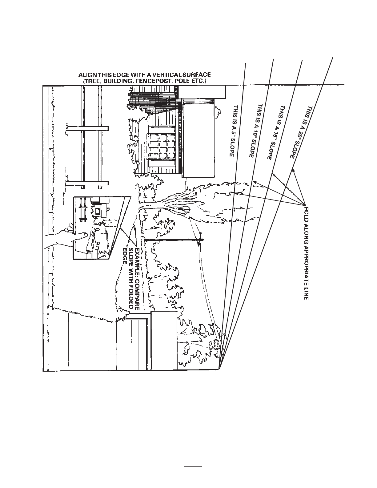
Slope Chart
MĆ4402
7

8

Safety and Instruction Decals
Safety decals and instructions are easily visible to the operator and are located near any
area of potential danger. Replace any decal that is damaged or lost.
106-9305
100-6140
108-5599
9
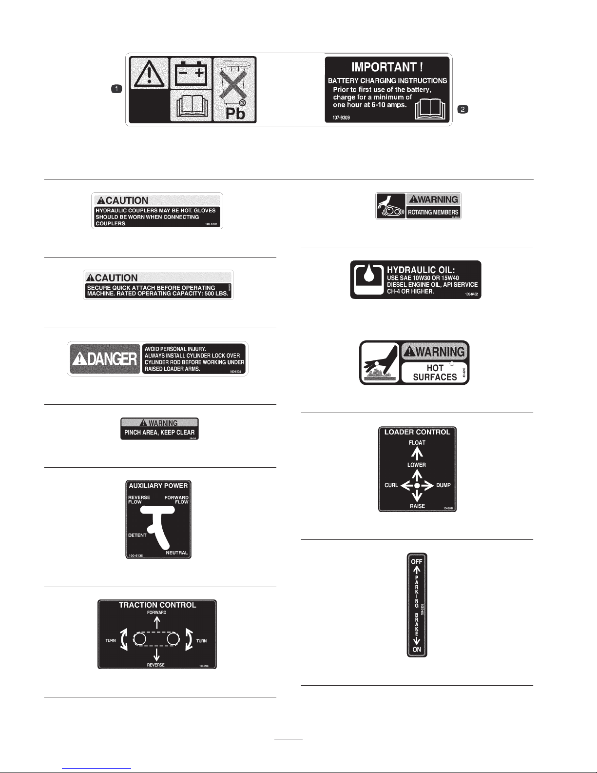
107-9309
1. Warning—read the Operator’s Manual for information on charging the battery; contains lead; do not discard.
2. Read the Operator’s Manual.
80-8040
100-6101
100-6132
100-6135
100-6141
100-6136
105-8432
80-8290
104-2837
100-6138
104-2838
10
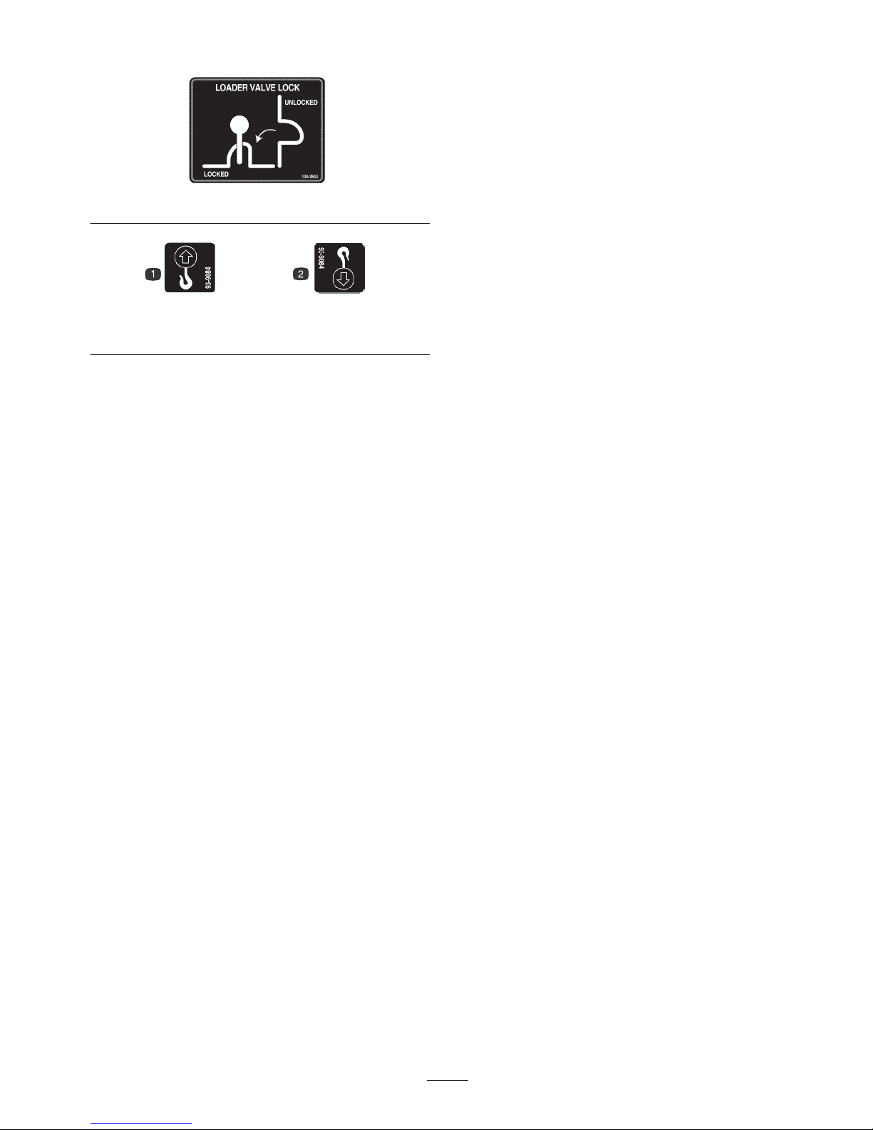
104-2844
93-9084
1. Lift point 2. Tie-down point
11
Setup
Charging the Battery
Warning
CALIFORNIA
Proposition 65 Warning
Battery posts, terminals, and related accessories
contain lead and lead compounds, chemicals
known to the State of California to cause cancer
and reproductive harm. Wash hands after
handling.
1. Open the rear access cover; refer to Opening the Rear
Access Cover, page 24.
2. Remove filler caps from the battery.
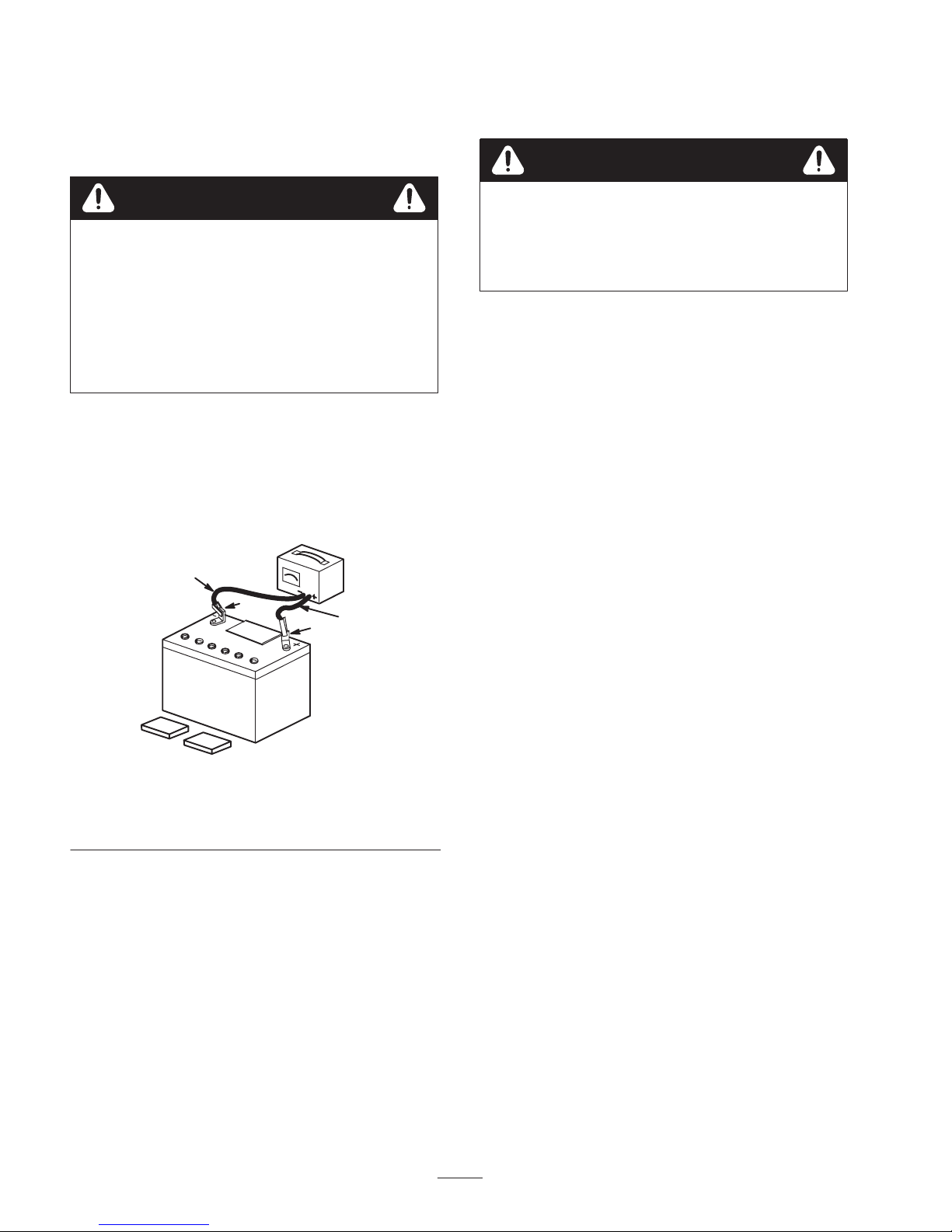
3. Connect a battery charger to the battery posts (Fig. 1).
Charge the battery at a rate of 6 to 10 amperes for a
minimum of 1 hour (12 volts).
4
Warning
Charging the battery produces gases that can
explode.
Never smoke near the battery and keep sparks
and flames away from battery.
4. When the battery is fully charged, disconnect the
charger from the electrical outlet and from the
negative and positive battery posts (Fig. 1).
5. Install the filler caps after the battery is fully charged.
6. Close the rear access cover.
1. Positive post
2. Negative post
2
Figure 1
3
1
1254
3. Charger red (+) wire
4. Charger black (–) wire
12

Specifications
Specifications and design are subject to change without
notice.
TX 420, Model 22306
Attachments
Many attachments are available for use with the traction
unit. These attachments allow you to to perform many
different functions with the traction unit such as hauling
materials, digging holes, grading, and more. Contact your
Toro dealer for a list of all approved attachments and
accessories.
Width 34 inches (86 cm)
Length 71 inches (180 cm)
Height 43 inches (109 cm)
Weight 1880 lb (853 Kg)
Operating capacity 500 lb (227 Kg)
Tipping capacity 1530 lb (694 Kg)
Wheelbase 31.2 inches (79 cm)
Dump height (with
narrow bucket)
Reach—fully raised
(with narrow bucket)
Height to hinge pin
(narrow bucket in the
highest position)
47 inches (119 cm)
22 inches (55 cm)
66 inches (168 cm)
TX 425, Model 22307
Width 41 inches (104 cm)
Important Use only Toro-approved attachments.
Length 71 inches (180 cm)
Height 43 inches (109 cm)
Weight 2060 lb (935 Kg)
Operating capacity 500 lb (227 Kg)
Tipping capacity 1530 lb (694 Kg)
Wheelbase 31.2 inches (79 cm)
Dump height (with
narrow bucket)
Reach—fully raised
(with narrow bucket)
Height to hinge pin
(narrow bucket in the
highest position)
47 inches (119 cm)
22 inches (55 cm)
66 inches (168 cm)
13
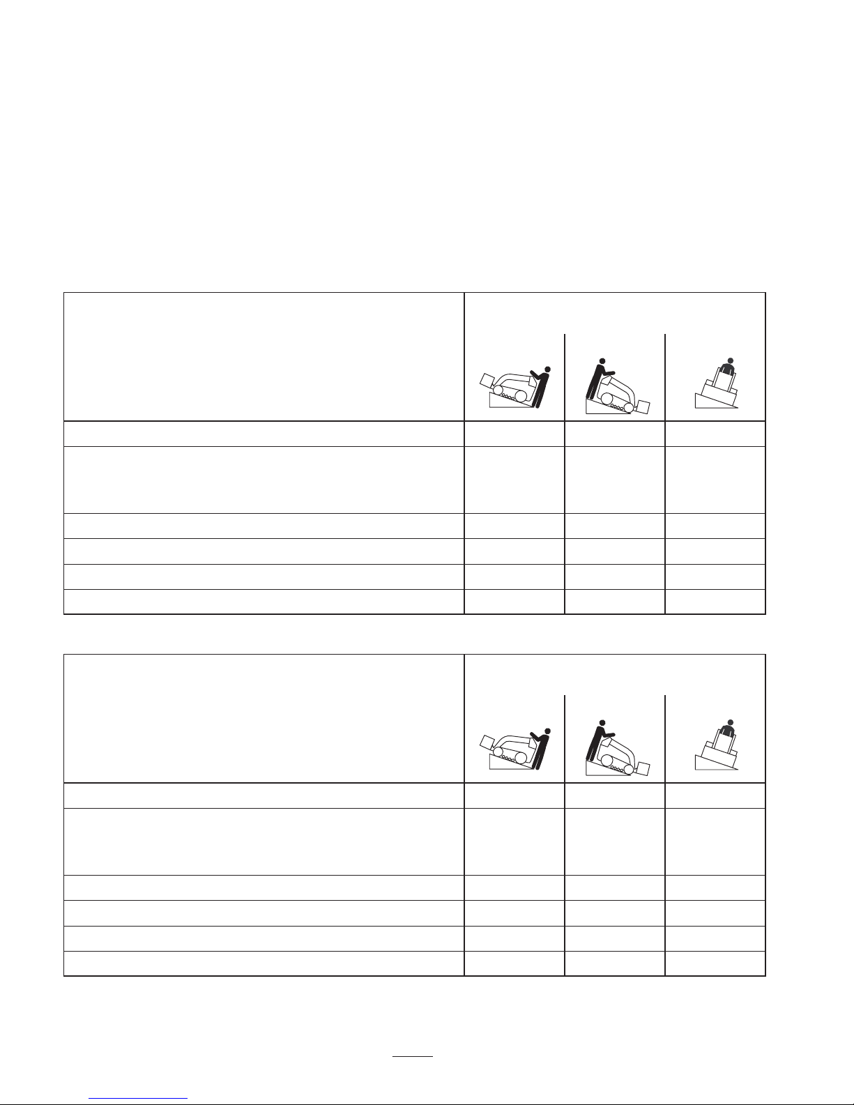
Stability Data
The following tables list the maximum slope recommended for the traction unit in the positions listed in the tables. Slopes
over the listed degree may cause the traction unit to become unstable. The data in the tables assume that the loader arms
are fully lowered; raised arms may affect the stability.
In each attachment manual is a set of three stability ratings, one for each hill position. To determine the maximum slope
you can traverse with the attachment installed, find the degree of slope that corresponds to the stability ratings of the
attachment. Example: If the attachment installed on a TX 420 traction unit has a Front Uphill rating of B, a Rear Uphill
rating of D, and a Side Uphill rating of C, then you could drive forward up a 20° slope, rearward up a 12° slope, or
sideways on a 14° slope, as listed in the following table for the TX 420 traction unit.
TX 420, Model 22306
Maximum Recommended Slope
when Operating with:
Front Uphill Rear Uphill Side Uphill
Configuration
Traction unit without attachment 11° 21° 19°
Traction unit with an attachment rated with one of the following
stability ratings for each slope position:
A
B
C
D
E
25° 25° 20°
20° 20° 18°
17° 17° 14°
10° 12° 9°
5° 5° 5°
TX 425, Model 22307
Maximum Recommended Slope
when Operating with:
Front Uphill Rear Uphill Side Uphill
Configuration
Traction unit without attachment 12° 20° 23°
Traction unit with an attachment rated with one of the following
stability ratings for each slope position:
A
B
25° 25° 25°
22° 22° 22°
C
D
E
18° 16° 16°
10° 10° 10°
5° 5° 5°
14
 Loading...