

Page 1

Turf Sweeper 4800
Model No. 44044—Serial No. 240000001 and Up
Form No. 3350–447 Rev A
Operator’s Manual
English (EN)
Page 2

Contents
Introduction 3. . . . . . . . . . . . . . . . . . . . . . . . . . . . . . . . .
Safety 3. . . . . . . . . . . . . . . . . . . . . . . . . . . . . . . . . . . . . .
Supervisor’s Responsibilities 3. . . . . . . . . . . . . . . . .
Before Operating 3. . . . . . . . . . . . . . . . . . . . . . . . . .
While Operating 4. . . . . . . . . . . . . . . . . . . . . . . . . . .
While Dumping 5. . . . . . . . . . . . . . . . . . . . . . . . . . .
Maintenance 5. . . . . . . . . . . . . . . . . . . . . . . . . . . . . .
Safety and Instruction Decals 7. . . . . . . . . . . . . . . . .
Specifications 9. . . . . . . . . . . . . . . . . . . . . . . . . . . . . . . .
General Specifications 9. . . . . . . . . . . . . . . . . . . . .
Optional Equipment 10. . . . . . . . . . . . . . . . . . . . . . . .
Loose Parts 10. . . . . . . . . . . . . . . . . . . . . . . . . . . . . . . . . .
Before Operating 10. . . . . . . . . . . . . . . . . . . . . . . . . . . . .
Grass Baffle 10. . . . . . . . . . . . . . . . . . . . . . . . . . . . . .
Check Tire Pressure 10. . . . . . . . . . . . . . . . . . . . . . . .
Check Crankcase Oil 11. . . . . . . . . . . . . . . . . . . . . . .
Fill Fuel Tank With Gasoline 11. . . . . . . . . . . . . . . . .
Check Hydraulic System Oil 12. . . . . . . . . . . . . . . . .
Check Torque of Wheel Nuts 13. . . . . . . . . . . . . . . . .
Know Your Controls 14. . . . . . . . . . . . . . . . . . . . . . . . . .
Operation 17. . . . . . . . . . . . . . . . . . . . . . . . . . . . . . . . . . .
Checking Interlock System 17. . . . . . . . . . . . . . . . . .
Operating Characteristics 17. . . . . . . . . . . . . . . . . . . .
Pushing or Towing Sweeper 18. . . . . . . . . . . . . . . . . .
Transporting Sweeper 18. . . . . . . . . . . . . . . . . . . . . .
Sweeper Operation 18. . . . . . . . . . . . . . . . . . . . . . . . .
While Sweeping 19. . . . . . . . . . . . . . . . . . . . . . . . . . .
Dumping the Hopper 19. . . . . . . . . . . . . . . . . . . . . . .
Lubrication 20. . . . . . . . . . . . . . . . . . . . . . . . . . . . . . . . . .
Lubricate Fittings and Bearings 20. . . . . . . . . . . . . . .
Maintenance 21. . . . . . . . . . . . . . . . . . . . . . . . . . . . . . . . .
Changing Engine Oil and Filter 21. . . . . . . . . . . . . . .
General Precleaner and Air Cleaner Maintenance 22.
Clean and Lubricate Foam Precleaner 22. . . . . . . . . .
Service Air Cleaner Paper Element 22. . . . . . . . . . . .
Clean Air Intake/Cooling Areas 23. . . . . . . . . . . . . . .
Check Spark Plug Gap and Condition 23. . . . . . . . . .
Changing Hydraulic Oil And Filter 23. . . . . . . . . . . .
Checking Hydraulic Lines and Hoses 25. . . . . . . . . .
Fuel Filter Replacement 25. . . . . . . . . . . . . . . . . . . . .
Sweeper Reel Height Adjustment 25. . . . . . . . . . . . .
Belt Removal/Installation 26. . . . . . . . . . . . . . . . . . . .
Clutch Switch Adjustment 26. . . . . . . . . . . . . . . . . . .
Electric Brake Clutch Adjustment 26. . . . . . . . . . . . .
Clutch Testing 27. . . . . . . . . . . . . . . . . . . . . . . . . . . .
Adjusting Parking Brake 27. . . . . . . . . . . . . . . . . . . .
Adjusting Traction Pedal 27. . . . . . . . . . . . . . . . . . . .
Steering Chain Adjustment 28. . . . . . . . . . . . . . . . . .
Replacing Sweeper Reel Fingers 28. . . . . . . . . . . . . .
Hopper and Reel Clean Out 28. . . . . . . . . . . . . . . . . .
Wheel Motor Axle Nut Torque 28
Battery Storage 29. . . . . . . . . . . . . . . . . . . . . . . . . . . .
Battery Care 29. . . . . . . . . . . . . . . . . . . . . . . . . . . . . .
Troubleshooting 30. . . . . . . . . . . . . . . . . . . . . . . . . . . . . .
Hydraulic Schematic 31. . . . . . . . . . . . . . . . . . . . . . .
Electrical Schematic 32. . . . . . . . . . . . . . . . . . . . . . . .
Recommended Maintenance Schedule 33. . . . . . . . .
Daily Maintenance Checklist 34. . . . . . . . . . . . . . . . .
Storage 35. . . . . . . . . . . . . . . . . . . . . . . . . . . . . . . . . . . . .
The Toro General Commercial Products Warranty 36. . .
. . . . . . . . . . . . . . .
W 2003 by The Toro Company
8111 Lyndale Avenue South
Bloomington, MN 55420-1196
All Rights Reserved
Printed in the USA
2
Page 3

Introduction
Safety
Read this manual carefully to learn how to operate and
maintain your product properly. The information in this
manual can help you and others avoid injury and product
damage. Although Toro designs and produces safe
products, you are responsible for operating the product
properly and safely.
Whenever you need service, genuine Toro parts, or
additional information, contact an Authorized Service
Dealer or Toro Customer Service and have the model and
serial numbers of your product ready. The two numbers are
stamped on a plate which is located on the blower housing.
Write the product model and serial numbers in the space
below:
Model No.
Serial No.
This manual identifies potential hazards and has special
safety messages that help you and others avoid personal
injury and even death. Danger, Warning, and Caution are
signal words used to identify the level of hazard. However,
regardless of the hazard, be extremely careful.
Danger signals an extreme hazard that will cause serious
injury or death if you do not follow the recommended
precautions.
Hazard control and accident prevention are dependent
upon the awareness, concern, and proper training of the
personnel involved in the operation, transport,
maintenance, and storage of the machine. Improper use
or maintenance of the machine can result in injury or
death. To reduce the potential for injury or death,
comply with the following safety instructions.
Supervisor’s Responsibilities
• Ensure operators are thoroughly trained and familiar
with the Operator’s Manual and all decals on the
machine.
• Establish your own special procedures and work rules
for unusual operating conditions (e.g., slopes too steep
for machine operation, adverse weather conditions,
etc.).
Before Operating
• Read, understand and follow the instructions in the
Operator’s Manual and on the machine before starting.
Become familiar with all controls and know how to stop
quickly. A free replacement manual is available by
sending complete Model and Serial Number to:
The Toro Company
8111 Lyndale Avenue South
Minneapolis, Minnesota 55420–1196
Warning signals a hazard that may cause serious injury or
death if you do not follow the recommended precautions.
Caution signals a hazard that may cause minor or moderate
injury if you do not follow the recommended precautions.
This manual uses two other words to highlight information.
Important calls attention to special mechanical
information and Note: emphasizes general information
worthy of special attention.
• NEVER allow children to operate the machine. NEVER
allow adults to operate the machine without proper
instruction. Only trained operators who have read this
manual should operate this machine.
• NEVER operate the machine while under the influence
of drugs or alcohol.
• Become familiar with the controls and know how to
stop the engine quickly.
• Keep all shields, safety devices, and decals in place. If a
shield, safety device, or decal becomes damaged,
malfunctioning, or illegible, repair or replace it before
operation is commenced. Also tighten loose
nuts and bolts to ensure machine is in safe operating
condition.
• Always wear substantial shoes. Do not operate machine
while wearing sandals, tennis shoes, or sneakers or
when barefoot. Do not wear loose–fitting clothing that
could get caught in moving parts and possibly cause
injury. Wearing safety glasses, safety shoes, long pants,
and a helmet is advisable and required by some local
ordinances and insurance regulations.
• Do not alter this equipment in any manner which may
cause hazardous conditions.
3
Page 4

• Safety interlock switches are for the operators
protection. Disconnected or malfunctioning safety
interlock switches could allow the machine to operate in
an unsafe manner and may cause personal injury.
– Do not disconnect the safety interlock switches.
– Check the operation of the switches daily to be sure
the interlock system is operating correctly.
– If a switch is malfunctioning, replace it before
operating the machine.
– Replace switches every 2 years to be sure of
maximum safety.
• In certain conditions gasoline is extremely flammable
and highly explosive. A fire or explosion from gasoline
can burn you and others and cause property damage.
Caution must be used when storing or handling
gasoline.
– Do not fill fuel tank while engine is running or hot
or when machine is in an enclosed area. Vapors may
build up and be ignited by a spark or flame source
many feet away. DO NOT SMOKE while filling the
fuel tank to prevent possibility of explosion.
– Always fill fuel tank outside and wipe up any spilled
gasoline before starting engine.
– Use a funnel or spout to prevent spilling gasoline
and fill tank to about 1 inch (25 mm) below the
filler neck.
– Store gasoline in a clean, safety approved container
and keep the cap in place on the container.
– Keep gasoline in a cool, well ventilated place; never
in an enclosed area such as a hot storage shed.
– To assure volatility, do not buy more than a 30 day
supply of gasoline.
While Operating
• Rotating parts can cause serious personal injury. Keep
hands and feet away from sweeper reels while machine
is running. Keep hands, feet, hair, and clothing away
from all moving parts to prevent injury. NEVER
operate the machine with covers, shrouds, or guards
removed.
• Do not run the engine in a confined area without
adequate ventilation. Exhaust fumes are hazardous and
could possibly be deadly.
• Operator should be seated when starting the engine and
remain seated whenever the machine is in motion.
Operator should keep both hands on steering wheel
whenever possible.
• DON’T TAKE AN INJURY RISK! When a person or
pet appears unexpectedly in or near the sweeping area,
STOP SWEEPING. Careless operation, combined
with terrain angles, ricochets, or missing or damaged
guards, can lead to thrown object injuries. Do not
resume sweeping until area is cleared.
• NEVER carry passengers.
• ALWAYS look to the rear of machine before backing up
and assure no one is behind the machine.
• When. starting the engine:
– Sit on operator’s seat and engage parking brake.
– Make sure traction pedal is in neutral and Reel PTO
Engagement handle is in the OFF position
(disengaged).
– After engine is started, release parking brake and
keep foot off traction pedal. Machine must not
move. If movement is evident, the neutral
mechanism is adjusted incorrectly; shut off engine
and adjust until machine does not move when
traction pedal is released. (Refer to Adjusting
Traction Pedal, (page 27.) If engine does not crank,
check interlock switch connections.
• Do not touch engine, muffler, or muffler shield while
engine is running or soon after it has stopped because
these areas may be hot enough to cause a burn.
• Tip over can cause serious injury or death.
– NEVER operate on steep slopes.
– Sweep slopes up and down, never across the face.
– When going uphill or downhill, do not stop or start
suddenly.
– Stay alert for holes in the terrain or other hidden
hazards. To avoid tipping or loss of control, do not
drive close to a ditch, creek, or drop off.
– If engine stalls or machine loses headway and
cannot make it to the top of a slope, do not turn
machine around. Always back slowly straight down
the slope.
• Using the machine demands attention. Failure to
operate machine safety may result in an accident, tip
over of the machine, and possible serious injury or
death. Drive carefully. To prevent tipping or loss of
control:
– Operate only in daylight or when there is good
artificial light.
– Drive slowly.
– Watch for holes or other hazards.
– Use care when backing machine.
– Do not drive close to a sand trap, ditch, tall curb,
creek, or other hazard.
– Reduce speed when making sharp turns and when
turning on a hillside.
4
Page 5

– Avoid sudden stops and starts.
– Do not go from reverse to forward or forward to
reverse without first coming to a complete stop.
– Do not attempt sharp turns or abrupt maneuvers or
other unsafe driving actions that may cause loss of
control.
– Watch out for traffic when near or crossing roads.
Always yield the right–of–way.
• Operator must be skilled and trained in how to drive on
hillsides. Failure to use caution on slopes or hills may
cause loss of control, possibly resulting in personal
injury or death.
• Before getting off seat:
– Move traction pedal to neutral position and remove
foot from pedal.
Maintenance
• Hydraulic fluid escaping under pressure can penetrate
skin and do serious damage. Keep body and hands away
from pin hole leaks or nozzles that eject high pressure
hydraulic fluid. Use cardboard or paper to find
hydraulic leaks. Fluid accidentally injected into the skin
must be surgically removed within a few hours by a
doctor familiar with this form of injury or gangrene
may result.
• Accidental starting of engine by others while
maintenance is being performed could cause injury.
Before servicing or making adjustments to the machine:
– Stop engine.
– Set parking brake.
– Remove key from ignition switch.
– Set parking brake and set Reel PTO Engagement
handle to the OFF position (disengaged).
– Shut engine off and remove key from ignition
switch. Wait for all movement to stop before getting
off seat.
• Whenever the machine is left unattended, be sure
engine is stopped, Reel PTO Engagement handle is in
OFF position (disengaged), and key is removed from
ignition.
While Dumping
• Moving hopper door and dumping debris can cause
serious injury. Stay clear of hopper while machine is
backing up or dumping.
• Keep bystanders a safe distance from hopper when
operating to dump debris or when opening and closing
hopper door.
• Under rare circumstances wet, compressed grass
clippings may generate heat. Always empty the hopper
before storing the unit.
• Raising and lowering of hopper door could cause injury
to bystanders or pets. Keep bystanders and pets a safe
distance from hopper when operating to dump debris or
when opening and closing hopper door.
• To avoid the risk of electrical shock, dump hopper only
in area clear of overhead wires and other obstructions.
• NEVER dump hopper on a slope. Always dump hopper
on level ground.
• Set Reel PTO Engagement handle to OFF (disengaged)
before dumping.
• Unexpected movement of the machine caused by an
improperly adjusted traction pedal may cause personal
injury. When foot is removed from traction pedal, the
machine should stop; it must not move in either
direction. It machine does move, do not operate until
neutral assembly has been repaired or adjusted.
• Accidental movement of machine due to parking brake
not being set may cause personal injury. The hydrostatic
transmission will not, at any time, act as a parking brake
for the machine. To engage parking brake, pull back on
lever. Whenever the engine is shut off, the parking
brake must be engaged to prevent accidental movement
of the machine.
• Engine must be running so final adjustment of the
traction adjustment cam can be performed. To guard
against possible personal injury, keep hands, feet, face,
and other parts of the body away from the muffler, other
hot parts of the engine, and other rotating parts.
• Perform only those maintenance instructions described
in this manual. If major repairs are ever needed or
assistance desired, contact an Authorized TORO
Distributor.
• Failure to maintain proper torque could result in failure
or loss of wheel and may result in personal injury.
– Torque wheel motor axle nuts to 200–400 ft.–lb.
– Torque rear wheel lug nuts to 45–55 ft.–lb.
• To reduce potential fire hazard, keep the engine free of
excessive grease, grass, leaves, and accumulations of
dirt.
• Make sure all hydraulic line connectors are tight, and all
hydraulic hoses and lines are in good condition before
applying pressure to the system.
5
Page 6

• Performing maintenance on machine not properly
supported with jack stands may cause machine to fall
and could cause injury.
• Do not over speed the engine by changing the governor
settings. Maximum engine rpm with no load is 3000
rpm. To ensure safety and accuracy, have an Authorized
TORO Distributor check maximum engine speed with a
tachometer.
• Engine must be shut off before checking oil or adding
oil to the crankcase.
• If wheel is removed for maintenance or repairs on the
wheel, brake, or hydraulic wheel motor, when
remounting wheel ALWAYS ensure that the wheel
motor axle nut is torqued to 200–400 ft.–lb.
• To be sure of optimum performance and safety, always
purchase genuine TORO replacement parts and
accessories. Replacement parts and accessories made by
other manufacturers could be dangerous. Altering this
machine in any manner may affect the machine’s
operation, performance, or durability, or its use may
result in injury or death. Such use could void product
warranty of The Toro Company.
• NEVER attempt to service the gas springs located on
hopper and hopper door. These springs are under high
loads and improper handling ran result in bodily harm.
Special tools are required to replace worn or damaged
gas springs; contact an Authorized TORO Distributor.
6
Page 7
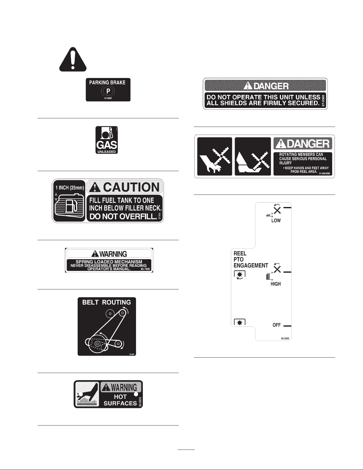
Safety and Instruction Decals
Safety decals and instructions are easily visible to the operator and are located near any area
of potential danger. Replace any decal that is damaged or lost.
87-6020
53-4420
67-5360
01-506-0080
27-7310
85-7490
98-8880
95-0390
80-9350
7
Page 8
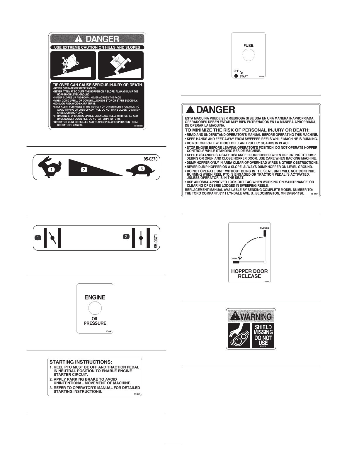
1. Fast
2. Continuous variable
setting
95-0384
01-506-0090
95-0370
3. Slow
95-0387
95-0371
1. Choke—on 2. Choke—off
95-0383
95-0389
95-0388
88-8950
8
Page 9

Specifications
General Specifications
Type
Engine
Battery
Fuel System 5 gallon (18.9 liter) tank.
Electrical
Traction System
Controls
Three wheeled, front steer, rear drive, one person ride–on turf sweeper with welded
steel frame and integral hopper for collecting debris.
Manufacturer: Kohler, Model CH1 BS, air cooled, 4 cycle
Horsepower: 18 @ 3600 RPM
Maximum Torque: 30 ft.–lb. @ 2500 RPM
Compression Ratio: 8.5. I
Displacement: 38.1 cu. in. (624 CC)
Oil Capacity w/filter: 2.1 quarts (2 liters)
Governor: Mechanical
Governor Limit: 3000 RPM
Idle Speed: 1200 RPM
Air Cleaner–High density paper element with oiled foam precleaner
Fuel Filter: 15 micron in–line filter
12 volt with 370 cold cranking amps. (CCA) at 0_ F. Type 24.
Type 24. 12 volt with 370 Cold Cranking Amps (CCA) at 0_ F. Electrical circuit is
fused at 10.0 Amps.
Sundstrand Series 15 pump coupled to Parker/Ross Model MS 10 wheel motors.
Filtration – 25 micron suction line filter (replaceable spin on element).
Foot pedal control with cable to ramped neutraling device on hydrostatic pump with
eccentric neutral adjust.
Throttle, choke, Reel PTO Engagement handle, parking brake, hopper release
handle, and ignition switch are all hand–operated. Forward/reverse traction pedal is
foot operated.
Gauges Hour meter, hydraulic vacuum gauge, and engine oil pressure warning light.
Electric clutch with brake. Automatically engages when Reel PTO Engagement
Reel Drive
Steering Manual, 14 in. soft touch, 3 position tilt steering wheel, 6 to 1 ratio.
Brakes Rear 6 in. drums with hand lever actuated to dual cables.
Tires, Wheels
Seat High–back cushion with slide adjust.
Interlock Switches
Hopper
Handle lowers reels (2 heights). Sweeping pick–up with two counter–rotating finger
reels, baffles and skirts. Reels rotate at 1100 RPM, and effectively pick up light
debris on turf up to 5 mph.
Front (1)–18 x 8.5–8 in. turf tread.
Rear (2)–18 x 9.5–8 in. ribbed tread. All tires 4 ply rating, tubeless type.
Prevents engine starting if traction pedal or Reel PTO Engagement handle are
engaged. Stops engine if operator leaves seat with either traction pedal or PTO
switch engaged.
Stationary, 1.25 cu. yd. capacity, with deflectors and grass filling baffles. Gas strut
supported rear dumping door, with integral discharge duct and wire mesh screen
for directing dust and air away from operator.
9
Page 10

General Specifications (continued)
Weight: 1600 lb.
Payload/Operator: 740 lb.
Ground Speed: 6.5 mph.
General Specifications
(approx.)
Note: Specifications and design subject to change without notice.
Width Overall: 70.0 in.
Height Overall: 67.0 in.
Height Overall: (with optional ROPS): 86.0 in.
Length Overall: 111.0 in.
Curb Clearance: 4 in.
Optional Equipment
ROPS/Seat Belt Package Available from
Authorized TORO
Distributor
Spark Arrestor Kohler Part No.
25–189–02
Loose Parts
Note: Use this chart as a checklist to ensure that all parts have been received. Without these parts, total setup cannot be
completed.
Description
Operator’s Manual 1 Read before operating the machine.
Kohler Engine Owners Manual 1 Read before operating the machine.
Parts Catalog 1
Registration Card 1 Fill out and return to Toro.
Before Operating
Grass Baffle
The sweeper comes with a hopper baffle extension
installed. This extension greatly enhances the filling
capacity of the hopper. You may find that the particular
debris that you are sweeping tends to fall back into the
hopper inlet and clogs the reels. When this occurs removal
of the extension should alleviate hopper clogging. It you
are sweeping fine dry material such as thatch or grass
clippings, the baffle extension should be used. When
sweeping larger debris such as oak leaves, you may prefer
to remove the extension.
Qty. Use
Check Tire Pressure
Check tire pressure every eight hours or daily to assure
proper levels.
1. With lower air pressure, turf compaction and tire marks
are minimized. Optimum pressure is 10–15 psi on front
and rear tires. Lower pressure should not be used for
heavy payloads or tire damage may result. Do not
exceed the maximum pressure. Maximum air pressure
in front tire is 22 psi and rear tires is 24 psi.
Important When replacing tires, use only replacements
approved for the Turf Sweeper. Use of tires not approved
may cause turf damage.
1. To remove the hopper baffle extension, remove the (5)
bolts. Store the fasteners and the extension in a safe
location.
10
Page 11
Check Crankcase Oil
The engine is shipped with 2.1 quarts (2 liters) of oil (with
filter) in the crankcase; however, level of oil must be
checked before the engine is first started.
1. Position the sweeper on a level surface and make sure
engine is off.
2. Remove the dipstick and wipe it with a clean rag. Push
dipstick down into the tube and ensure it is fully seated.
Pull dipstick out of the tube and check level of oil.
1
Figure 1
1. Dipstick 2. Filler cap
3. Install dipstick into tube.
4. If oil is low, use a clean rag to clean area around oil fill
cap. Remove cap and add oil until level is up to, but not
over, the F mark on the dipstick. Add the oil slowly and
check the level often during this process. DO NOT
OVERFILL. The engine requires high–quality detergent
oil having the American Petroleum Institute (API)
“service classification” SG or SH. Oil viscosity
(weight) must be selected according to average
anticipated ambient temperature. Temperature/viscosity
recommendations are as follows:
A. Above 0_ F (–18_ C)–Use l0W–30 or 10W–40.
B. Below 32_ F (0_ C)–Use 5W–20 or 5W–30.
Note: Using other than service class SG or SH oil or
extending oil change intervals longer than recommended
can cause engine damage.
2
Fill Fuel Tank With Gasoline
Danger
IN CERTAIN CONDITIONS GASOLINE IS
EXTREMELY FLAMMABLE AND HIGHLY
EXPLOSIVE. A FIRE OR EXPLOSION FROM
GASOLINE CAN BURN YOU AND OTHERS
AND CAUSE PROPERTY DAMAG
• Caution must be used when storing or handling
gasoline.
• Do not fill fuel tank while engine is running or
hot or when machine is in an enclosed area.
Vapors may build up and be ignited by a spark
or flame source many feet away.
• To prevent the possibility of explosion, DO NOT
SMOKE while filling the fuel tank.
• Always fill fuel tank outside and wipe up any
spilled gasoline before starting engine.
• Use a funnel or spout to prevent spilling gasoline
before starting engine. Fill tank to about I inch
(25 mm) below the filler neck.
• Store gasoline in a clean, safety approved
container and keep the cap in place on the
container.
• Keep gasoline in a cool, well ventilated place,
never in an enclosed area such as a hot storage
shed.
• To assure volatility, do not buy more than a
30–day supply of gasoline.
• Gasoline is a fuel for internal combustion
engines; therefore, do not use it for any other
purpose. Since many children like the smell of
gas, keep it out of their reach because the fumes
are explosive and dangerous to inhale.
Fuel Type – For best results use only clean, fresh,
UNLEADED gasoline with a pump sticker octane rating of
87 or higher. In countries using the Research method, it
should be 90 octane minimum.
THE TORO COMPANY STRONGLY
RECOMMENDS THE USE OF FRESH, CLEAN,
UNLEADED REGULAR GRADE GASOLINE IN
TORO GASOLINE–POWERED PRODUCTS.
UNLEADED GASOLINE BURNS CLEANER,
EXTENDS LIFE, AND PROMOTES GOOD
STARTING BY REDUCING THE BUILD–UP OF
COMBUSTION CHAMBER DEPOSITS.
E.
Important Check level of oil after every 5 hours of
operation or daily. Change oil and filter after every 50
hours of operation. Change oil and filter more
frequently when engine is operated in extremely dusty
or dirty conditions.
Note: Gasoline/Alcohol Blends – Gasohol (up to 10% ethyl
alcohol, 90% unleaded gasoline by volume) may be used.
Do not use other gasoline/alcohol blends.
Note: Gasoline/Ether Blends–Methyl Tertiary Butyl Ether
(MTBE) and unleaded gasoline blends (up to a maximum
of 15% MTSE by volume) may be used. Do not use other
gasoline/ether blends.
11
Page 12

1. Use a clean rag to clean area around fuel tank cap.
2. Remove the cap from the fuel tank and fill the 5 gallon
tank to within 1 inch (25 mm) from the top with
unleaded gasoline. Install fuel cap tightly.
1
Figure 2
1. Fuel tank cap
3. Wipe up any gasoline that may have spilled to prevent a
fire hazard.
Check Hydraulic System Oil
Danger
HYDRAULIC FLUID ESCAPING UNDER
PRESSURE CAN PENETRATE SKIN AND DO
SERIOUS DAMAGE.
• Keep body and hands away from pin hole leaks
or nozzles that eject high pressure hydraulic
fluid. Use cardboard or paper to find hydraulic
leaks. Fluid accidentally injected into the skin
must be surgically removed within a few hours
by a doctor familiar with this form of injury or
gangrene may result.
Expected Ambient Temperatures
Recommended Oil Start–Up Average Daily Temperature
Mobil DTE 13M or equivalent ISO VG 32
Mobil DTE 26 or equivalent ISO VG 68
Less than 40_ F–50_ F
Greater than 60_ F–70_ F
Check level of hydraulic fluid before engine is first started
and daily thereafter. The hydraulic system is designed to
operate on Mobil DTE 13M or equivalent ISO VG 32
Wide–temperature, shear–stable hydraulic fluid with
controlled low–temperature flow properties and anti–wear
protection. The reservoir is filled at the factory with
approximately 28 quarts of Mobil DTE 13M hydraulic
fluid. Hydraulic oil viscosity (weight) must be selected
according to average anticipated ambient temperature.
Temperature/viscosity recommendations are as follows:
Less than 80_ F (26.7_ C)
(4.5_ C–10_ C)
Greater than 80_ F (26.7_ C)
(15.5_ C–21_ C)
Important Using Mobil DTE 26 or equivalent ISO VG
68 hydraulic oil when temperature at start–up is less than
40_ F (4.5_ C) could cause serious hydraulic system
damage.
1. Position the sweeper on a level surface and make sure
engine is off.
2. Remove dipstick cap (located under operators seat)
from filler neck and wipe it with a clean rag. Insert
dipstick cap onto filler neck; then remove it and check
level of oil. If level is below the L mark on dipstick, add
sufficient hydraulic fluid to bring to the F mark. DO
NOT OVERFILL.
12
Page 13

Important To prevent system contamination, clean top
of hydraulic oil containers before opening. Assure pour
spout and funnel are clean. When adding oil to the
hydraulic system, use a funnel with a fine screen–200
mesh–and ensure funnel and oil are clean. This procedure
prevents accidental contamination of the hydraulic oil
which will damage the hydraulic system.
1
Figure 3
1. Dipstick cap
Check Torque of Wheel Nuts
Warning
Failure to maintain proper torque could result in
failure or loss of wheel and could result In personal
Injury. Torque rear wheel lug nuts to 45–55 ft. lb.
1
Figure 4
1. Lug nut
13
Page 14

Know Your Controls
Choke (Fig. 5)–To start a cold engine, move the choke
control forward to close the choke. After engine starts,
regulate choke to keep engine running smoothly. As soon
as possible, move the choke backward to open the choke. A
warm engine requires little or no choking.
1 2 3 4 5 76
adding oil does not cause light to go out when engine is
restarted, turn off engine immediately and contact your
local Authorized TORO Distributor for assistance.
Ignition Key Switch (Fig. 5) – The key switch, which is
used to start and stop the engine, has three positions: OFF,
RUN, and START. Rotate key clockwise (START) to
engage starter motor. When engine starts, release key and it
will move automatically to the RUN position. To shut
engine off, rotate key counterclockwise to the OFF
position.
8
9
1. Throttle control
2. Choke
3. Reel PTO engagement
handle
4. Engine oil pressure
warning light
5. Parking brake
Figure 5
11
10
6. Fuse
7. Hour meter
8. Hydraulic vacuum gauge
9. Tow valve knob
10. Hydraulic oil filter
11. Ignition key switch
Fuse: (Fig. 5) – Provides 10 amps ignition circuit
protection. If fuse is blown the engine will not crank.
Hour Meter (Fig, 5) – Indicates total hours of machine
operation. The hour meter starts to function whenever the
key switch is rotated to the ON position.
Reel PTO Engagement Handle (Fig. 5) – The engagement
of the sweeper reels is done with the Reel PTO
Engagement handle. The handle also sets the height of the
fingers. There are two settings for finger height. The height
of the fingers is initially set so the fingers touch the top of
the turf. The first setting will set the fingers at 1–1/4 inch
from the surface. The second setting sets the fingers at
5/8 inch from the surface.
Hydraulic Vacuum Gauge (Fig. 5) – When the hydraulic
oil filter becomes dirty, the vacuum level within the
hydraulic system will increase. Check vacuum gauge after
each day’s operation and before shutting off engine. (Refer
to Changing Hydraulic Oil and Filter)
Tow Valve Knob (Fig. 5) – The tow valve knob is located
in the front of the hydraulic pump. With the knob turned
fully clockwise the machine is in the operating position.
With the knob turned 1/2 turn counterclockwise the
machine is in towing position. After completion of mowing
operation, and before starting engine, close tow valve
securely by rotating fully clockwise. Do not exceed 5–8
ft.–lb. torque.
Throttle Control (Fig. 5)–Throttle is used to operate
engine at various speeds. Moving throttle forward increases
engine speed; backward decreases engine speed. The
throttle regulates the speed of the sweeper reels and, in
conjunction with traction pedal, controls ground speed of
the sweeper.
Engine Oil Pressure Warning Light (Fig. 5)–Light glows
if engine oil pressure drops below a safe level while engine
is running. It light flickers or remains ON, stop machine,
turn off engine, and check oil level. It oil level is low, but
Parking Brake (Fig. 5)–Whenever the engine is shut off,
the parking brake must be engaged to prevent accidental
movement of the machine. To engage the parking brake,
pull back on lever. To release the parking brake push
forward on lever. Make sure parking brake is released
before moving machine. If the machine is parked on a
grade, make sure parking brake is applied.
Tilt Steering Lever (Fig. 6) – Lever on left side of steering
tower. Lift lever to adjust steering wheel to desired fore or
aft operating position and release lever to lock in place.
14
Page 15

Seat Adjusting Lever (Fig. 6) – To adjust fore and aft
position of seat, move lever on left side of seat outward,
slide seat to desired position, and release lever so it will
lock in position.
2
1
Figure 6
1. Tilt steering lever 2. Seat adjusting lever
Caution
UNEXPECTED MOVEMENT OF THE
MACHINE CAUSED BY AN IMPROPERLY
ADJUSTED TRACTION PEDAL MAY CAUSE
PERSONAL INJURY.
• When foot is removed from traction pedal, the
machine should stop; it must not move In either
direction. If machine does move, do not operate
until. neutral assembly has been repaired or”
adjusted; refer to Adjusting Traction Pedal.
Traction Pedal (Fig. 8) – The traction pedal is foot
operated and is used to make the machine move forward
and backward and to stop the machine. Using the heel and
toe of the right foot, depress top of pedal to move forward
and bottom of pedal to move rearward, To stop machine
remove foot from pedal. Ground speed is proportionate to
how far pedal is depressed, For maximum ground speed
with no load, traction pedal must be fully depressed while
throttle is in full position. Allowing pedal to move to
neutral position will stop machine.
Seat Prop (Fig. 7) – To lock seat in tilted forward position,
rotate the seat prop up until positive stop.
1
Figure 7
1. Seat prop
Maximum forward speed is approximately 6.5 mph (10.5
Km/hr). Maximum forward speed while sweeping is 5 mph.
To get maximum power under heavy load or when
ascending a hill, have throttle in full position while
depressing traction pedal slightly to keep engine rpm high.
When engine rpm begins to decrease, release traction pedal
slightly to allow rpm to increase. When sweeping wet
debris or a thick layer of material, slower speeds may need
to be used.
1
1. Traction pedal
15
Figure 8
Page 16

Caution
ACCIDENTAL MOVEMENT OF MACHINE
DUE TO PARKING BRAKE NOT BEING SET
MAY CAUSE PERSONAL INJURY.
• The hydrostatic transmission will not, at any
time, act as a parking brake for the machine. To
engage parking brake, pull back on lever.
• Whenever the engine is shut off, the parking
brake must be engaged to prevent accidental
movement of the machine.
Hopper Door Release Handle (Fig. 9) – The hopper is
dumped manually with the hopper door release handle.
1
Figure 10
1. Hopper door locking knob
1
Figure 9
1. Hopper door release handle
Hopper Door Locking Knob (Fig. 10) Locks hopper door
in the raised position.
Seat Locking Spring Flap (Fig. 11) Locks seat in lowered
position.
1
Figure 11
1. Seat Locking Spring Flap
16
Page 17

Operation
Warning
B. A disconnected or malfunctioning safety interlock
switch could allow the engine to continue running
when the Reel PTO Engagement handle is in the
HIGH or LOW (engaged) position or the traction
pedal is depressed with the operator off the seat.
ROTATING PARTS CAN CAUSE SERIOUS
PERSONAL INJURY
• Keep hands and feet away from sweeper reels
while machine is running.
• Keep hands, feet, hair, and clothing away from
all moving parts to prevent injury.
• NEVER operate the machine with covers,
shrouds, or guards removed.
1. Place the unit on a level surface and apply the parking
brake.
2. Remove foot from traction pedal and make sure pedal is
in neutral position.
3. With the throttle 1/2 open and the choke closed, insert
key into ignition switch and rotate it clockwise to start
engine. Release key when engine starts and open the
choke gradually.
Note: Do not run starter motor more than 10 seconds at a
time or premature starter failure may result. If engine fails
to start after 10 seconds, turn key to OFF position, recheck
controls and procedure. wait 60 seconds and repeat starter
operation.
4. When engine is started for the first time, after engine oil
change, hydraulic oil change or hydraulic service work,
operate the machine in forward and reverse for one to
two minutes. Also operate the Reel PTO Engagement
and Hopper Door Release to verity proper operation of
all parts.
5. Turn steering wheel to the left and right to check
steering response. Shut off engine and check fluid
levels. Check for oil leaks, loose parts and any
noticeable malfunctions.
Checking Interlock System
The purpose of the safety interlock system is to prevent the
engine from cranking or starting unless the traction pedal is
in neutral and the Reel PTO Engagement handle is in the
OFF (disengaged) position. In addition, the engine will stop
when the Reel PTO is engaged or the traction pedal is
depressed with the operator off the seat. Indications of a
disconnected or malfunctioning interlock switch are:
A. A disconnected or malfunctioning safety interlock
switch could allow the engine to be started when the
traction pedal is not in the neutral position or the
Reel PTO Engagement handle is in the HIGH or
LOW (engaged) position.
Caution
SAFETY INTERLOCK SWITCHES ARE FOR
THE OPERATOR’S PROTECTION.
DISCONNECTED OR MALFUNCTIONING
SAFETY INTERLOCK SWITCHES COULD
ALLOW THE MACHINE TO OPERATE IN AN
UNSAFE MANNER AND MAY CAUSE
PERSONAL INJURY.
• Do not disconnect the safety interlock switches.
• Check operation of the switches daily to be sure
the interlock system is operating correctly.
• If a switch is malfunctioning, replace it before
operating the machine.
• Replace switches every 2 years to be sure of
maximum safety.
1. Sit on operator’s seat and engage parking brake.
2. Move the Reel PTO Engagement handle to the OFF
position and remove foot from traction pedal (neutral
position).
3. Rotate the ignition key to START. Engine should crank.
If engine cranks, proceed to step 4. If engine fails to
crank, there may be a malfunction in the interlock
system.
4. Raise off the seat and position the Reel PTO
engagement handle to either the HIGH or LOW
position while the engine is running. The engine should
stop within 2 seconds. If the engine stops, the switch is
operating correctly; proceed to step 5. If the engine does
not stop, there is a malfunction in the interlock system.
5. Raise off the seat and depress the traction pedal while
the engine is running and the Reel PTO is disengaged.
The engine should stop within 2 seconds. If the engine
stops, the switch is operating correctly; continue
operation. If the engine does not stop, there is a
malfunction in the interlock system.
Operating Characteristics
Practice driving the TURF SWEEPER 4800 before initial
operation because the hydrostatic transmission and its
characteristics are different than some turf maintenance
machines. Some points to consider when operating the
sweeper are the engine speed, transmission speed, and the
load on the sweeper reels.
17
Page 18

The engine provides power to both the hydrostatic
transmission and the sweeper reels. An increasing load on
the hydrostatic transmission, such as hill climbing or a full
hopper, will result in less power available to the sweeper
reels, thereby decreasing the efficiency of debris pickup. To
maintain enough power for the sweeper reels while
operating, regulate traction pedal to keep engine speed high
and somewhat constant. This allows the engine to provide
sufficient power to the sweeper reels while maintaining a
satisfactory ground speed. By contrast, pushing down too
far on the traction pedal will increase load on the engine
and decrease the power available to the sweeper reels.
A good rule to follow is: decrease ground speed as the load
on the sweeper reels increases; and increase ground speed
as load on the sweeper reels decreases. This allows the
engine, working with the transmission, to maintain the
proper ground speed while maintaining a high sweeper reel
speed necessary for efficient pickup. Allow traction pedal
to move upward as engine speed decreases, and depress
pedal slowly as speed increases. By comparison, when
driving from one work area to another – with no load and
sweeper reel disengaged – have throttle in the full position
and depress traction pedal slowly but fully to attain
maximum ground speed. Sweeping, in some instances, can
be improved by slower ground speed.
11
Figure 12
1. Front tie–down
Before stopping the engine, disengage all controls and
move the throttle to the slow position. Moving the throttle
to the slow position reduces high engine speed, noise and
vibration. Allow the engine to idle for a few seconds then
turn ignition key OFF to stop engine.
Pushing or Towing Sweeper
In case of an emergency, the sweeper can be pushed or
towed for a short distance. However, TORO does not
recommend this as standard procedure.
Important Do not push or tow the sweeper faster
then 2 – 3 mph because the drive system may be
damaged. If sweeper must be moved a considerable
distance, transport it on a truck or trailer.
1. Locate the tow valve knob in the front of the hydraulic
pump.
2. Rotate tow valve knob 1/2 turn counterclockwise.
3. After completion of towing operation, and before
starting engine, close tow valve securely by rotating it
fully clockwise. Do not exceed 5 – 8 ft. lb. torque.
Transporting Sweeper
When transporting the sweeper use only the tie–downs
welded into the frame of machine to secure it to a trailer.
Use of hopper linkages, steering wheels, or anything other
than the proper tie–down locations could cause damage to
the machine.
1
Figure 13
1. Rear tie–down
1
Sweeper Operation
1. Release the parking brake.
2. With the throttle 1/2 open and the choke closed, insert
key into ignition switch and rotate it clockwise to start
engine. Release key when engine starts and open choke
gradually.
3. Using the toe of your foot, press the traction pedal
forward to move forward. Using the heel of your foot,
press down on the traction pedal to move backward.
Practice moving both ways to get a feel of the machine.
For quick braking, when going forward, depress the
heel of the traction pedal until hydrostatic transmission
reaches neutral. For emergency braking, completely
remove foot from the traction pedal.
4. Run engine to full throttle.
5. As you are moving forward, engage the Reel PTO
Engagement handle to engage the finger reels.
Important NEVER run the reels In one place for any
amount of time because the turf will be damaged.
18
Page 19

While Sweeping
Dumping the Hopper
Danger
TIP OVER CAN CAUSE SERIOUS INJURY OR
DEATH.
• NEVER operate on steep slopes.
• Sweep slopes up and down, never across the
face.
• When going uphill or downhill, do not stop or
start suddenly.
• Stay alert for holes in the terrain or other
hidden hazards. To avoid tipping or loss of
control, do not drive close to a ditch, creek or
drop off.
• If machine stops going uphill, disengage reels
and back slowly downhill. Do not attempt to
turn.
1. When the hopper is full, disengage reels and transport
to dumping area. When the hopper is full the sweeper
will no longer pickup as efficiently, leaving or throwing
material back on the ground.
Danger
TIP OVER/ELECTRICAL SHOCK COULD
CAUSE SERIOUS INJURY OR DEATH.
• NEVER dump hopper on a slope. Always dump
hopper on level ground.
• Dump only in area clear of overhead wires and
other obstructions.
1. Place the machine on a level surface and in position to
dump.
Caution
RAISING AND LOWERING OF HOPPER
DOOR COULD CAUSE INJURY TO
BYSTANDERS OR PETS.
• Keep bystanders and pets a safe distance from
hopper when opening and closing hopper door.
2. Pull the hopper door release handle forward to dump
the hopper.
3. Move machine forward to separate dumped material
from hopper.
Important Debris caught between hopper and
hopper door could cause damage to the machine. Make
sure that debris Is removed from area where hopper
and hopper door meet before closing hopper door.
4. When hopper is empty, return the hopper door to the
closed position.
19
Page 20

Lubrication
Lubricate Fittings and
Bearings
The sweeper has four self–sealing bearings and two grease
fittings that must be lubricated regularly with No, 2 General
Purpose Lithium Base Grease. it machine is operated under
normal conditions, lubricate all bearings and bushings after
every 50 hours of operation or immediately after every
washing. Bearings and bushings must be lubricated daily
when operating conditions are extremely dusty and dirty.
Dusty and dirty operating conditions could cause dirt to got
into the bearings and bushings, resulting in accelerated
wear.
1. Lubricate grease fittings:
A. Hydraulic pump neutral device (Fig. 14).
B. Front wheel bearing hub (Fig. 15).
2. Lubricate the four self–sealing bearings mounted on the
sweeper reels with a No. 2 Lithium based grease
(Fig. 16 & 17).
3. Lubricate the 14 gate pivot bearings (7 on each side of
hopper) with lightweight general purpose lubricating
oil.
Figure 15
Figure 14
Figure 16
Figure 17
20
Page 21

Maintenance
Changing Engine Oil and Filter
Important This product contains an exhaust emission
certified engine. Always refer to the engine manufacturer’s
owner’s manual for maintenance and service requirements
concerning the emission control system.
Note: For further information on engine operation,
maintenance, and repair of engine, refer to engine
manufacturer’s owner’s manual. In some cases TORO may
recommend more frequent maintenance intervals than the
engine manufacturer. This is due to the extremely dirty and
dusty conditions that turf sweepers operate in.
Warning
ACCIDENTAL STARTING OF ENGINE BY
OTHERS WHILE MAINTENANCE IS BEING
PERFORMED MAY CAUSE PERSONAL
INJURY.
• Before servicing or making adjustments to the
machine:
• Stop engine.
• Set parking brake.
• Remove key from ignition switch.
Check oil after each day’s operation or each time machine
is used. For new engine, change oil and filter after the first
5 hours of operation. Thereafter change oil and filter every
50 hours or operation. It possible, run engine just before
changing oil. Warm oil flows better and carries away more
impurities than cold oil.
1. Position machine on a level surface with engine off,
parking brake set, and key removed from ignition
switch.
2. To keep debris out of engine, clean the area around the
oil fill cap/dipstick and oil filter before removing.
3. Remove oil drain plug, oil fill cap, and dipstick. Be sure
to allow ample time for complete drainage.
4. Reinstall drain plug.
5. Remove the old filter. Wipe off surface where oil filter
mounts. Allow oil filter to drain.
6. Apply a thin coating of new oil to the rubber gasket on
replacement oil filter.
7. Install the replacement oil filter to the filter adapter.
Turn the oil filter clockwise until rubber gasket contacts
the filter adapter, then tighten the filter an additional
1/2 turn.
2
1
Figure 18
1. Oil drain plug 2. Oil filter
8. Slowly fill crankcase to the F mark on the dipstick..
Always check the oil level with the dipstick before
adding more oil. DO NOT OVERFILL. When changing
only the filter, add 1/2 pint (0.24 liters) of new oil. The
engine requires high–quality detergent oil having the
American Petroleum Institute (API) ”service
classification” SG or SH. Oil viscosity (weight) must be
selected according to anticipated ambient temperature.
Temperature/viscosity recommendations are as follows:
A. Above 0_ F (–18_ C)–Use l0W–30 or l0W–40
B. Below 32_ F (0_ C)–Use 5W–20 or 5W–30
Note: Using other than service class SG or SH oil or
extending oil change intervals longer than recommended
can cause engine damage.
9. Reinstall dipstick and oil cap and tighten securely.
10. Start the engine and check for oil leaks. Correct any
leaks before placing engine into service. Check oil to
make sure it is up to but not over the F mark on the
dipstick.
Important To prevent extensive engine wear or
damage, always maintain the proper oil level in the
crankcase. Never operate the engine with the oil level
below the L mark or over the F mark on the dipstick.
21
Page 22

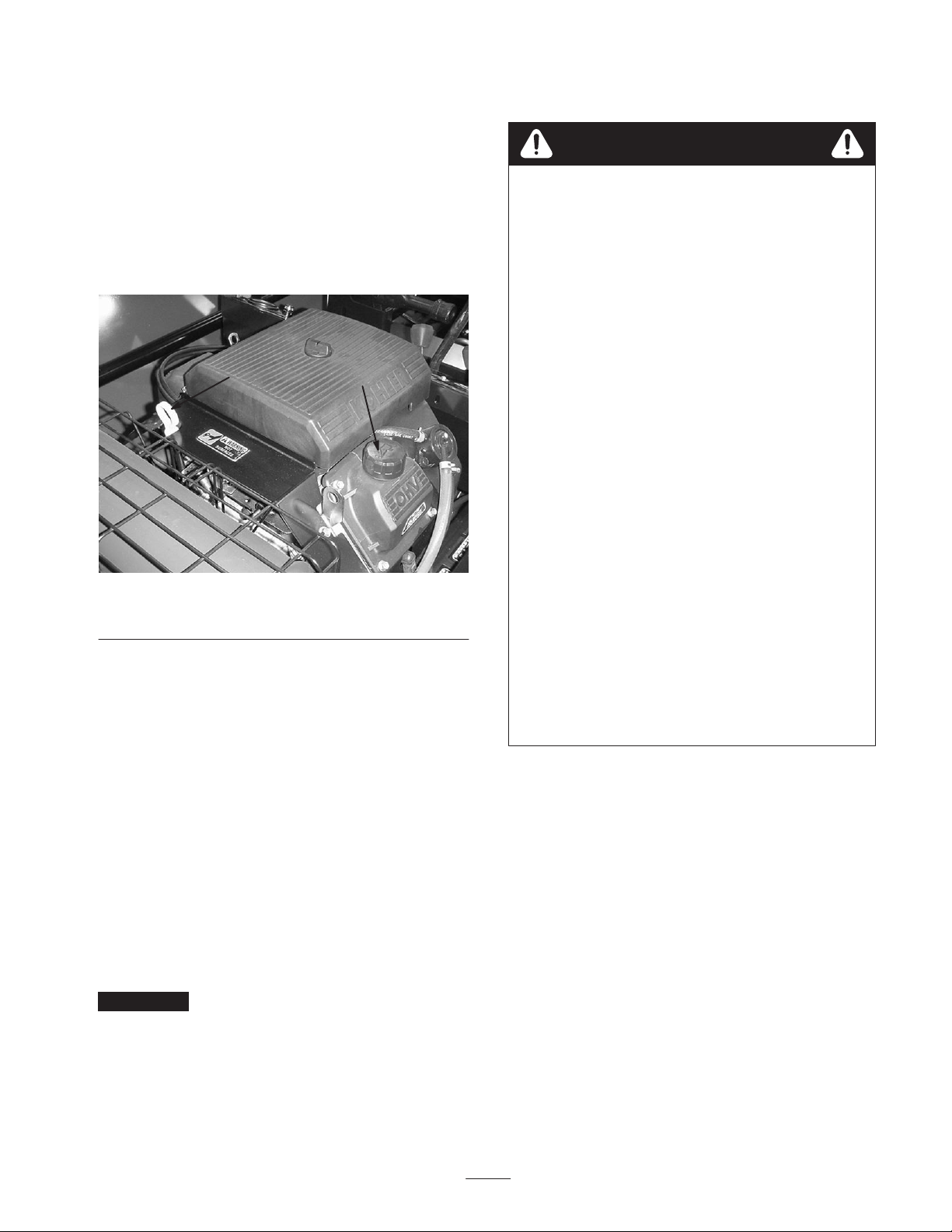
General Precleaner and Air
Cleaner Maintenance
The engine is equipped with a replaceable, high density
paper air cleaner element and an oiled foam precleaner
which surrounds the paper element.
1
2
3
4
Figure 19
1. Precleaner
2. Air cleaner cover
Check the air cleaner daily before starting the engine.
Check for buildup of dirt and debris around the cleaner
system. Keep this area clean. Also check for loose or
damaged components. Replace all bent or damaged air
cleaner components.
3. Air cleaner cover nut
4. Air cleaner
2
1
Figure 20
1. Air cleaner cover 2. Air cleaner cover knob
3. Remove precleaner from paper element.
4. Wash precleaner in warm water with detergent. Rinse
precleaner thoroughly until all traces of detergent are
eliminated. Squeeze out excess water. (Do not wring.)
Allow precleaner to air dry.
5. Saturate the precleaner with new engine oil. Squeeze
out excess oil.
6. Reinstall the precleaner over the air cleaner.
7. Reinstall the air cleaner cover. Secure cover with
retaining knob.
Note: Operating the engine with loose or damaged air
cleaner components could allow unfiltered air into the
engine, causing premature wear and failure.
Clean and Lubricate Foam
Precleaner
Wash and reoil precleaner every 25 hours of operation
(more often if under extremely. dusty and dirty conditions).
1. Turn engine off, set parking brake, and remove key
from ignition switch.
2. Loosen the air cleaner cover knob and remove air
cleaner cover.
Service Air Cleaner Paper
Element
Every 100 hours of operation (more often under extremely
dusty or dirty conditions) check the air cleaner paper
element. Replace the element as necessary.
1. Turn engine off, set parking brake, and remove key
from ignition switch.
2. Loosen the cover retaining knob and remove cover.
3. Remove the precleaner from the air cleaner paper
element.
4. Remove air cleaner cover nut, air cleaner cover, and air
cleaner paper element.
5. Do not wash the air cleaner paper element or use
pressurized air, as this will damage element. Replace a
dirty, bent, or damaged element. Handle now elements
carefully; do not use if the sealing surfaces are bent or
damaged.
22
Page 23

6. When servicing air cleaner, check the air cleaner base.
Make sure it is secured and not bent or damaged. Check
element cover for damage or improper fit. Replace all
damaged air cleaner components.
Note: Before reassembling air cleaner make sure rubber
seal is in position around stud. Inspect and make sure it is
not damaged. Seal with the element cover.
7. Reinstall the air cleaner paper element, precleaner,
element cover, element cover nut, and air cleaner cover.
Secure cover with retaining knob.
Clean Air Intake/Cooling Areas
0.030 in (0.76mm)
Figure 21
To ensure proper cooling, chuck and clean grass screen,
cooling fins, and other external surfaces of the engine daily.
Every 100 hours of operation (more often under extremely
dusty or dirty conditions), remove the blower housing and
other cooling shrouds. Clean the cooling fins and external
surfaces as necessary. Make sure the cooling shrouds are
reinstalled.
Important Operating the engine with a blocked grass
screen, dirty or plugged cooling fins, and/or cooling
shrouds removed will cause damage due to overheating.
Check Spark Plug Gap and
Condition
Air gap between center and side electrodes of the spark
plug increases gradually during normal operation of the
engine. Check condition of electrodes after 200 hours of
operation. Recommended air gap is 0.030 in. (0.76 mm).
Changing Hydraulic Oil And Filter
Important A cracked, fouled, dirty, or otherwise
malfunctioning spark plug must be replaced. Do not sand
blast, scrape, or clean electrodes by using a wire brush
because grit may eventually release from the plug and fall
into the cylinder. The result is usually a damaged engine.
1. Turn engine off, set parking brake, and remove key
from ignition switch.
2. Before removing spark plug, clean the area around the
base of the plug to keep dirt and debris out of the
engine.
3. Remove plug and check condition of side and center
electrodes, and center insulator to assure there is no
damage. Replace plug if worn or if reuse is
questionable.
4. Check the gap using a wire feeler gauge. Adjust the gap
between center and side electrodes to 0.030 in,
(0.76mm) by carefully bending the ground electrode.
5. Reinstall spark plug into the cylinder head. Torque
spark plug to 18–22 ft. lb.
6. Replace high tension leads onto spark plugs.
The hydraulic oil must be changed yearly. The hydraulic oil
filter must be changed initially at 50 hours, and thereafter
yearly. The hydraulic oil and/or filter must also be changed
if hydraulic vacuum gauge reads, and stays, in the red zone.
The hydraulic system is designed to operate on Mobil
DTE 13M or equivalent ISO VG 32 wide–temperature,
shear–stable hydraulic fluid with controlled
Expected Ambient Temperatures
Recommended Oil Start–Up Average Daily Temperature
Mobil DTE 13M or equivalent ISO VG 32
Mobil DTE 26 or equivalent ISO VG 68
Less than 40_ F–50_ F
(4.5_ C–10_ C)
Greater than 60_ F–70_ F
(15.5_ C–21_ C)
low–temperature flow properties and anti– wear protection.
The reservoir is filled at the factory with approximately 28
quarts of Mobil DTE 13M hydraulic fluid. Hydraulic oil
viscosity (weight) must be selected according to average
anticipated ambient temperature. Temperature/viscosity
recommendations are as follows:
Less than 80_ F (26.7_ C)
Greater than 80_ F (26.7_ C)
23
Page 24

Important Using Mobil DTE 26 or equivalent ISO VG
68 hydraulic oil when temperatures average below 80_ F
(26.7_ C) could cause serious hydraulic system damage.
The hydraulic vacuum gauge measures the vacuum levels
within the hydraulic system. When the hydraulic oil filter
becomes dirty, the vacuum level within the system will
increase. The vacuum level will also increase if the wrong
viscosity oil is used. (Refer to Expected Ambient
Temperatures table.) Check vacuum gauge after each day’s
operation, and before shutting off engine. The hydraulic
vacuum gauge (Fig. 6, Item 8) has three color–coded zones:
the green zone (gauge reads 1 – 5), the yellow zone (gauge
reads 4 – 6), and the red zone (gauge reads 7 – 31). It is
safe to operate machine with gauge reading in the green or
yellow zone. DO NOT continue to operate machine with
the gauge in the red zone. The hydraulic oil and/or filter
must be changed before operation can continue.
Note: When machine is first started and before the
hydraulic oil has had time to reach a stable operating
temperature (after approximately 2 hours of contiguous
operation), the vacuum gauge may read in the red zone. For
an accurate reading allow oil to reach a stable operating
temperature before checking vacuum gauge.
Important Do not continue to operate machine if
hydraulic vacuum gauge remains in the red zone after
hydraulic oil has reached stable operating temperature.
Continuing to operate machine with gauge in the red zone
may cause serious system damage.
1
Figure 22
1. Hydraulic oil drain plug
3. Clean area around hydraulic oil filter mounting area and
remove filter using a filter wrench.
Important If hydraulic oil becomes contaminated,
contact your local Authorized TORO Distributor because
the system must be flushed. Contaminated oil looks milky
or black when compared to clean oil. Continuing to operate
machine with contaminated hydraulic all could cause
system damage.
1. Position machine on a level surface shut engine off, set
parking brake, and remove key from the ignition switch.
2. Remove drain plug (located under the floorboard on
left–hand side) from reservoir and let hydraulic oil flow
into drain pan. Reinstall and tighten plug when
hydraulic oil stops draining.
1
Figure 23
1. Hydraulic oil filter
4. Lubricate the sealing gasket and hand turn until gasket
contacts filter head. Then tighten 3/4 turn further, filter
should now be seated.
5. Fill the hydraulic tank with approximately 28 quarts of
the proper hydraulic fluid.
Important To prevent system contamination, clean top
of hydraulic oil containers before opening. Assure pour
spout and funnel are clean. When adding oil to the
hydraulic system, use a funnel with a fine screen (200
24
Page 25

mesh) and ensure funnel and oil are clean. This procedure
prevents accidental contamination of the hydraulic oil
which will damage the hydraulic system.
6. Place all controls in the neutral or disengaged position
and start engine. Run engine at idle for 3–5 minutes to
circulate hydraulic fluid and remove any air trapped in
the system. Stop the engine and re–check the fluid level.
(Refer to Check Hydraulic System Oil)
7. Check all connections for leaks.
Danger
HYDRAULIC FLUID ESCAPING UNDER
PRESSURE CAN PENETRATE SKIN AND DO
SERIOUS DAMAGE.
• Keep body and hands away from pin hole leaks
or nozzles that eject high pressure hydraulic
fluid. Use a cardboard or paper to find
hydraulic leaks. Fluid accidentally injected into
the skin must be surgically removed within a
few hours by a doctor familiar with this form of
injury or gangrene may result.
Checking Hydraulic Lines and
Hoses
After every 100 hours of operation, check hydraulic lines
and hoses for leaks, kinked lines, loose mounting supports,
wear, loose fittings, weather deterioration, and chemical
deterioration. Make all necessary repairs before operating.
1
Figure 24
1. Fuel filter
3. Loosen the hose clamps at both ends of the filter and
pull lines off filter.
4. Install new filter with arrow on the filter body pointing
toward fuel pump.
5. Secure with hose clamps.
Sweeper Reel Height
Adjustment
The operator can freely alternate between two set heights
while sweeping. Higher settings may be required to sweep
taller turf and also avoid scalping on rough terrain, It
should also be noted that when scalping occurs mud and
debris will build up inside of the hopper throat. This debris
build–up will cause clogging and lower the sweeping
effectiveness. Lowering the sweeping height will be
required to compensate for finger wear and shorter turf. To
adjust the height of the two set sweeping settings:
Fuel Filter Replacement
A 15 micron in–line filter is incorporated into the fuel line.
Replace fuel filter after 100 hours of operation.
1. Place a drain pan under filter.
2. Clamp both fuel lines that connect to fuel filter so
gasoline cannot drain when lines are removed.
1. Position machine on a level surface, shut the engine off,
set the parking brake, and remove the key from the
ignition switch.
2. Remove the belt guards.
3. Locate the reel height adjusting nuts on both sides of
the machine.
4. Move the engagement handle to the High or Low
setting. Move the adjusting nuts so the front reel is at
desired level. Maximum distance between end of
fingers and ground is 2 1/8 inches with new fingers and
in high position.
5. Tighten reel height adjusting nuts.
25
Page 26

6. Adjust the left–hand side. It is very important that the
left side and right side are adjusted equally (from the
frame). Do not use the floor to adjust the
perpendicularity of the reel shaft to the sweeper frame.
7. Verify that there is no interference when the PTO
engagement handle is in OFF position.
Note: The inside and outside of the belt are not the same.
When looking at the front reel pulley (Fig. 25), with the
belt installed, there should be two wide grooves on either
side visible. Tighten the idler adjustment arm by pulling
rearward with approximately 30 lbs. Torque both clamping
bolts to 48 ft–lbs. Do not use a lever or a pry–bar for
mechanical advantage when tensioning the belt with the
idler adjustment arm.
6
2
3
7
1. Reel height adjusting nut
(right hand side)
2. Upper idler
3. Idler adjusting arm
4. Front reel pulley
5
Figure 25
5. Clutch switch adjustment
6. Electric clutch/brake
7. Upper drive belt
8. Clutch switch flag
1
8
4
Belt Removal/Installation
1. Position machine on a level surface, shut the engine off,
set the parking brake and remove the key from the
ignition switch.
2. Remove belt guards.
3. The upper or lower belt can be removed or installed
without removing both belts.
4. To remove the upper belt, loosen the upper idler
(Fig. 25) and remove belt from machine.
5. To install upper belt, first verity that the upper idler
(Fig. 25) is loosened and slides freely. Install belt on
machine. To tighten idler, push down on idler with
approximately 30 lbs. of force and tighten idler bolt. Do
not use a lever for mechanical advantage. Do not over
tension belt. An over–tensioned belt can cause
premature failure or wear. The electric clutch and
other reel drive components are subject to damage
when belts are over–tensioned.
6. To remove lower reversing belt, loosen the two bolts on
the rear idler adjustment arm (Fig. 25). Move
adjustment arm forward and remove belt.
7. To install lower reversing belt, push idler adjustment
arm forward. Install reversing belt.
8. Re–tension new belts after l0 hours of operation.
Caution
An incorrectly adjusted reel switch may cause
unintended engagement of the reels and could
cause injury.
Clutch Switch Adjustment
The clutch switch should never need adjusting. If the clutch
fails to engage or disengage according to the position of the
Reel PTO Engagement Handle, adjust the clutch switch.
1. Position machine on a level surface, shut the engine off,
set parking brake and remove the key from the ignition
switch.
2. Inspect the complete reel lift system including the reel
engagement handle. Look for any worn or bent
components that may cause the engagement switch to
be out of adjustment.
3. Replace or repair any damaged components.
If all reel lift system components are in proper condition,
adjust the reel switch bracket.
1. Place the PTO engagement handle in the OFF position.
2. Loosen the three bolts on the clutch switch bracket
(Fig. 25).
3. Slide the clutch switch bracket until there is 1/8” of the
clutch switch flag (Fig. 25) protruding through the
bottom of the clutch switch bracket.
4. Tighten the three bolts and reassemble in reverse order.
Electric Brake Clutch
Adjustment
Every 200 hours check for proper air gap on the electric
clutch brake. Failure to maintain the correct air gap could
result in clutch not engaging even though it is electrically
energized.
1. Position machine on a level surface, shut the engine off,
set the parking brake and remove the key from the
ignition switch.
26
Page 27

2. Adjust the air gap to .018” (.5mm) by inserting a
thickness gauge into the clutch inspection slots. Evenly
tighten the three lock nuts on clutch to reduce the air
gap.
1
Figure 26
1. Brake clutch inspection slot (3)
Clutch Testing
1. Position machine on a level surface with the engine off,
parking brake off, and the key removed from ignition
switch.
1. Position machine on a level surface, shut the engine off,
and remove the key from the ignition switch. Do not
set the parking brake.
Caution
Performing maintenance on machine not properly
supported with jack stands may cause machine to
fall and could cause injury.
2. Raise one rear wheel off floor and support with jack
stands under frame.
3. Loosen locknut on traction adjustment cam (located
under operators seat).
3
2
2. Disconnect the wire connector and connect a continuity
tester or ohm meter across the terminals of the clutch
wire connector. There should be continuity across the
terminals of the clutch connector. Resistance measured
through the clutch coil should be 3.03 ohms 5%. The
clutch can also be tested by connecting a 12 V DC
battery across the clutch connector terminals. The
clutch should engage as 12V DC is connected to the
clutch connector terminals.
Adjusting Parking Brake
Check adjustment every 200 hours of operation.
1. Position machine on a level surface with the engine off
and the key removed from the ignition switch.
2. Rotate knob until a force of 40–50 lb. is required to
actuate lever.
3. Tighten set screw after adjustment has been made.
Adjusting Traction Pedal
If the machine moves in either direction when traction
pedal is in the neutral position, the traction cam must be
adjusted.
1
Figure 27
1. Traction adjustment cam
2. Locknut
3. Cam hex
Warning
Engine must be running so final adjustment of the
traction adjustment cam can be performed. To
guard against possible personal injury, keep hands,
feet, face, and other parts of the body away from
the muffler, other hot parts of the engine, and
other rotating parts.
4. Start engine and rotate cam hex in both directions to
determine mid–position of neutral span.
5. Tighten locknut securing adjustment.
6. Always tighten both nuts when final adjustments are
completed.
7. Stop engine. Remove jack stands and lower machine to
shop floor.
27
Page 28

8. Test drive machine to be sure it does not creep.
Steering Chain Adjustment
The steering chain should be adjusted after 100 hours of
operation or when steering system is binding or excessive
play in the column occurs.
1. Adjust steering chain idler, by applying 5 lbs. of force
to the midpoint of the chain, until it deflects 0.25
inches.
Figure 29
1
Figure 28
1. Steering chain idler
Replacing Sweeper Reel
Fingers
Check condition of sweeper reel fingers after every 25
hours of operation. Excessively worn or damaged sweeper
reel fingers will affect the sweepers ability to effectively
pick up debris and must be replaced.
The Rubber Finger Puller (TORO Part No. 48–002–5691)
can be used to remove and install reel fingers.
To install new reel fingers:
Note: The puller may be used in either direction for right
or left handed use.
To remove reel fingers:
1. Place the end of the puller on the finger.
2. Push down in the same manner as installing the reel
finger.
Hopper and Reel Clean Out
1. Position machine on a level surface, shut the engine off,
set the parking brake, and remove the key from the
ignition switch.
2. Open hopper door and lock the door open by loosening
the locking knob (Fig. 10) and sliding bolt into notch.
Tighten looking knob.
3. Remove debris from hopper and reel area.
Wheel Motor Axle Nut Torque
Warning
Failure to maintain proper torque could result in
failure or loss of wheel and may result in personal
injury. Torque wheel motor axle nuts to 200 – 400
ft. lb.
1. Place the reel finger in the slot and pull as far as
possible.
2. Place the end of the puller on the finger.
3. Push down on puller to install finger.
28
Page 29

Battery Care
Warning
ELECTROLYTES CONTAINED IN BATTERIES
COULD CAUSE BURNS. GASSES PRODUCED
WHILE CHARGING ARE EXPLOSIVE AND IF
IGNITED BY SPARK OR FLAME MAY CAUSE
SERIOUS INJURY. ALSO NAUSEA MAY
RESULT IF GASSES ARE INHALED.
1
Figure 30
1. Wheel motor axle nut
Battery Storage
If the machine will be stored for more than 30 days, remove
the battery and charge it fully. Either store it on the shelf or
on the machine. Leave cables disconnected it stored on the
machine. Store the battery in a cool atmosphere to avoid
quick deterioration of the charge in the battery. To prevent
battery from freezing, make sure it is fully charged. The
specific gravity of a fully charged battery is 1.250.
• Wear safety glasses and rubber gloves when
working with electrolyte.
• Charge battery in a well ventilated place so
gasses produced while charging can dissipate.
• Keep open flames and electrical spark away
from the battery; DO NOT SMOKE.
• Unplug charger from electrical outlet before
connecting to or disconnecting charger leads
from battery posts.
1. Battery electrolyte level must be properly maintained
and the top of the battery kept clean. If the machine is
stored in a location on where temperatures are
extremely high, the battery will run down more rapidly
than if the machine is stored in a location where
temperatures are cool.
2. Keep top of battery clean by washing periodically with
a brush dipped in ammonia or bicarbonate of soda
solution. Flush the top surface with water after cleaning.
Do not remove the fill cap while cleaning.
3. Check battery cable connections every 50 hours of
operation. Battery cables must be tight on terminals to
provide good electrical contact.
1
1. Battery cover
Figure 31
Warning
Connecting cables to the wrong post could result in
personal injury and/or damage to the electrical
system.
4. If corrosion occurs at terminals, remove battery cover,
disconnect cables, negative (–) cable first and scrape
clamps and terminals separately. Reconnect cables,
positive (+) cable first and coat terminals with Grafo
112X skin over grease (TORO Part Number 505– 46) or
petroleum jelly,
5. Check the electrolyte level every .50 hours of operation
or, it machine is in storage, every 30 days.
6. Maintain cell level with distilled or demineralized
water. Do not fill cells above bottom of the fill ring,
inside each cell.
29
Page 30

Troubleshooting
Condition Possible Causes Corrective Action
Sweeper Not Picking Up 1. Missing or broken fingers.
2. Broken belt or improper
tension.
3. Check sheaves for sheared
key.
4. Finger height may be too low or
too high.
5. Hopper floor not seated inside
against the rear cross member.
Unit may be picking up but
throwing it through gap onto the
ground.
6. Screen in top of hopper door
may be clogged, blocking air
flow.
7. Build up on bottom of oil tank
compartment or rear reel
deflector above front reel.
Excessive Vibration 1. Check bearings on reel shaft. If
they are excessively hot, they
are probably damaged.
2. Foreign materials wrapped
around reel shaft.
3. Reels could be bent. Should be
within 0.015 for straightness.
4. Missing or broken sweeper
fingers.
5. Damaged belt
1. Replace missing or broken
fingers.
2. Replace belt/adjust tension.
3. Replace key.
4. Adjust height. See Sweeper
Reel Height Adjustment.
5. Bend hopper floor back to seal
hopper.
6. Clean out screen blockage.
7. Clean off any buildup on these
surfaces.
1. Replace any damaged
bearings.
2. Clean off any foreign objects.
3. Check shaft with dial calipers.
4. Replace fingers.
5. Replace belt.
30
Page 31

Hydraulic Schematic
31
Page 32

Electrical Schematic
32
Page 33

Recommended Maintenance Schedule
Maintenance Service
Interval
After first 5 hours • Change engine oil and filter.
After first 10 hours
Every 25 hours
Every 50 hours
Every 100 hours
Maintenance Procedure
• Check reel drive belts.
• Torque wheel lug nuts.
• Clean and lubricate foam pre–cleaner.
• Clean reel drive area.
• Check reel drive belts.
• Check battery fluid level.
• Lubricate gate pivots.
• Lubricate all grease fittings.
• Check battery cable connections.
• Change engine oil and filter.
• Replace air filter.
• Clean air intake/cooling areas.
• Check reel fingers.
• Replace fuel filter.
• Inspect condition of tires.
• Adjust steering chain.
Every 200 hours
Every 600 hours or
annually, whichever
occurs first
• Torque wheel lug nuts.
• Service spark plugs.
• Check electric brake clutch air gap.
• Check engine RPM (idle and full throttle).
• Drain and flush fuel tank.
• Inspect hopper and gate for damage.
• Replace hydraulic fluid and filter.
33
Page 34

Daily Maintenance Checklist
Duplicate this page for routine use.
For the week of:
Maintenance Check Item
Check safety interlock operation.
Check parking brake operation.
Check engine oil level.
Check hydraulic fluid level.
Check air filter precleaner.
Check engine cooling fins.
Check for unusual engine noises.
Check for unusual operating noises.
Check tire pressure.
Check hydraulic hoses for damage.
Check for fluid leaks.
Check instrument operation.
Check hopper screen.
Clean wrapped material from reels.
Check traction pedal operation.
Check rubber fingers.
1
Mon. Tues. Wed. Thurs. Fri. Sat. Sun.
Check steering chain adjustment.
Lubricate all grease fittings.
2
Touch up damaged paint.
1
.Replace if missing or broken
2
Immediately after every washing, regardless of the interval listed
Notation for Areas of Concern
Inspection performed by:
Item Date Information
1
2
3
4
5
6
7
8
9
34
Page 35

Storage
1. Thoroughly clean the sweeper so it is free of dirt, leaves
and debris.
2. Inflate tires to 22 psi.
3. Check all fasteners. Tighten as necessary.
4. Grease all grease fittings. Wipe off excess lubricant.
5. Drain and replace hydraulic fluid and filter. Inspect all
hydraulic lines and fittings. Replace if necessary. Refer
to the Maintenance section.
6. Check the tension and condition of the reel belts. Adjust
the tension if necessary.
7. Check the condition of the rubber fingers. Replace any
broken, missing, or worn fingers.
8. Service the battery and cables as follows:
A. Remove the battery terminals from the battery posts.
B. Clean the battery, terminals and posts with a wire
brush and baking soda solution.
C. Coat the cable terminals and battery posts with
Grafo 112X skin over grease (TORO Part Number
505–46), or petroleum jelly to prevent corrosion.
D. Slowly recharge the battery every 60 days for 24
hours to prevent lead sulfating of the battery.
Engine
1. Drain the engine oil from the crankcase and replace
drain plug.
2. Remove and discard the oil filter. Install a new oil filter.
3. Refill crankcase pan with 2.1 quarts (2 liters) of SG or
SH, 10W–30 motor oil.
4. Start the engine and run at idle speed for approximately
two minutes.
5. Stop the engine.
6. Thoroughly drain all fuel from the fuel tank, lines and
the fuel filter.
7. Flush the fuel tank with fresh,clean gasoline.
8. Re–secure all fuel system fittings.
35
Page 36

The Toro General Commercial Products Warranty
A Two-Year Limited Warranty
Conditions and Products Covered
The Toro Company and its affiliate, Toro Warranty Company,
pursuant to an agreement between them, jointly warrant your Toro
Commercial Product (“Product”) to be free from defects in
materials or workmanship for two years or 1500 operational
hours*, whichever occurs first. Where a warrantable condition
exists, we will repair the Product at no cost to you including
diagnosis, labor, parts, and transportation. This warranty begins
on the date the Product is delivered to the original retail purchaser.
* Product equipped with hour meter
Instructions for Obtaining Warranty Service
You are responsible for notifying the Commercial Products
Distributor or Authorized Commercial Products Dealer from whom
you purchased the Product as soon as you believe a warrantable
condition exists.
If you need help locating a Commercial Products Distributor or
Authorized Dealer, or if you have questions regarding your
warranty rights or responsibilities, you may contact us at:
Toro Commercial Products Service Department
Toro Warranty Company
8111 Lyndale Avenue South
Bloomington, MN 55420-1196
952-888-8801 or 800-982-2740
E-mail: commercial.service@toro.com
Owner Responsibilities
As the Product owner, you are responsible for required maintenance and adjustments stated in your operator’s manual. Failure
to perform required maintenance and adjustments can be grounds
for disallowing a warranty claim.
Items and Conditions Not Covered
Not all product failures or malfunctions that occur during the
warranty period are defects in materials or workmanship. This
express warranty does not cover the following:
• Product failures which result from the use of non-Toro
replacement parts, or from installation and use of add-on,
modified, or unapproved accessories
• Product failures which result from failure to perform required
maintenance and/or adjustments
• Product failures which result from operating the Product in an
abusive, negligent or reckless manner
• Parts subject to consumption through use unless found to be
defective. Examples of parts which are consumed, or used up,
during normal Product operation include, but are not limited to,
blades, reels, bedknives, tines, spark plugs, castor wheels,
tires, filters, belts, and certain sprayer components such as
diaphragms, nozzles, and check valves, etc.
• Failures caused by outside influence. Items considered to be
outside influence include, but are not limited to, weather,
storage practices, contamination, use of unapproved coolants,
lubricants, additives, or chemicals, etc.
• Normal “wear and tear” items. Normal “wear and tear” includes,
but is not limited to, damage to seats due to wear or abrasion,
worn painted surfaces, scratched decals or windows, etc.
Parts
Parts scheduled for replacement as required maintenance are
warranted for the period of time up to the scheduled replacement
time for that part.
Parts replaced under this warranty become the property of Toro.
Toro will make the final decision whether to repair any existing part
or assembly or replace it. Toro may use factory remanufactured
parts rather than new parts for some warranty repairs.
General Conditions
Repair by an Authorized Toro Distributor or Dealer is your sole
remedy under this warranty.
Neither The Toro Company nor Toro Warranty Company is
liable for indirect, incidental or consequential damages in
connection with the use of the Toro Products covered by this
warranty, including any cost or expense of providing substitute equipment or service during reasonable periods of
malfunction or non-use pending completion of repairs under
this warranty. Except for the Emissions warranty referenced
below, if applicable, there is no other express warranty. All
implied warranties of merchantability and fitness for use are
limited to the duration of this express warranty.
Some states do not allow exclusions of incidental or consequential
damages, or limitations on how long an implied warranty lasts, so
the above exclusions and limitations may not apply to you.
This warranty gives you specific legal rights, and you may also
have other rights which vary from state to state.
Note regarding engine warranty: The Emissions Control System
on your Product may be covered by a separate warranty meeting
requirements established by the U.S. Environmental Protection
Agency (EPA) and/or the California Air Resources Board (CARB).
The hour limitations set forth above do not apply to the Emissions
Control System Warranty. Refer to the Engine Emission Control
Warranty Statement printed in your operator’s manual or contained in the engine manufacturer’s documentation for details.
Countries Other than the United States or Canada
Customers who have purchased Toro products exported from the United States or Canada should contact their Toro Distributor (Dealer)
to obtain guarantee policies for your country, province, or state. If for any reason you are dissatisfied with your Distributor’s service or
have difficulty obtaining guarantee information, contact the Toro importer. If all other remedies fail, you may contact us at Toro Warranty
Company.
Part No. 374-0031 Rev. C
 Loading...