

Page 1

EnglishEspañolFrançaisItaliano
Turf Guard
®
Wireless Soil Monitoring System
Installation & Setup Manual
Sistema inalámbrico
de monitorización del suelo
Manual de instalación y configuración
Système de contrôle du sol sans fil
Manuel d’installation et de
programmation
Sistema wireless di monitoraggio del
terreno
Manuale di installazione e
approntamento
Page 2

Table of Contents
System Overview - - - - - - - - - - - - - - - - - - - - - - - - - - - - - - - - - - - - - - - - - - - 1
Pre-Installation Procedure - - - - - - - - - - - - - - - - - - - - - - - - - - - - - - - - - - - - - - -2
Creating Distributor Account - - - - - - - - - - - - - - - - - - - - - - - - - - - - - - - - - - - 2
Account Setup - - - - - - - - - - - - - - - - - - - - - - - - - - - - - - - - - - - - - - - - - - 2
Sensor Activation - - - - - - - - - - - - - - - - - - - - - - - - - - - - - - - - - - - - - - - - -4
Installation Procedures - - - - - - - - - - - - - - - - - - - - - - - - - - - - - - - - - - - - - - - - 4
Base Station Installation- - - - - - - - - - - - - - - - - - - - - - - - - - - - - - - - - - - - - - - -5
Installation - - - - - - - - - - - - - - - - - - - - - - - - - - - - - - - - - - - - - - - - - - - -5
Troubleshooting - - - - - - - - - - - - - - - - - - - - - - - - - - - - - - - - - - - - - - - - - 5
Repeater Installation - - - - - - - - - - - - - - - - - - - - - - - - - - - - - - - - - - - - - - - - - 6
Internal Repeater Installation - Toro Network VP Satellite - Plastic Pedestal - - - - - - - - - - - - - -6
Internal Repeater Installation - Toro Network LTC Plus Satellite - Plastic Pedestal - - - - - - - - - - -7
Internal Repeater Installation - Toro E-OSMAC Satellite - Plastic Pedestal - - - - - - - - - - - - - - 8
External Repeater Installation - Toro Network 8000 Satellite - Plastic Pedestal- - - - - - - - - - - - -9
External Repeater Installation - Rain Bird Par+ Satellite - Plastic Pedestal - - - - - - - - - - - - - - 10
External Repeater Installation - Metal Pedestal Satellites - - - - - - - - - - - - - - - - - - - - - - 11
Internal Repeater Start-Up Procedure - - - - - - - - - - - - - - - - - - - - - - - - - - - - - - - - 11
Sensor Installation - - - - - - - - - - - - - - - - - - - - - - - - - - - - - - - - - - - - - - - - - 11
Locating Buried Sensors- - - - - - - - - - - - - - - - - - - - - - - - - - - - - - - - - - - - - - - 12
Superintendent Training - - - - - - - - - - - - - - - - - - - - - - - - - - - - - - - - - - - - - - 12
Specications- - - - - - - - - - - - - - - - - - - - - - - - - - - - - - - - - - - - - - - - - - - - 12
ii
Page 3
System Overview
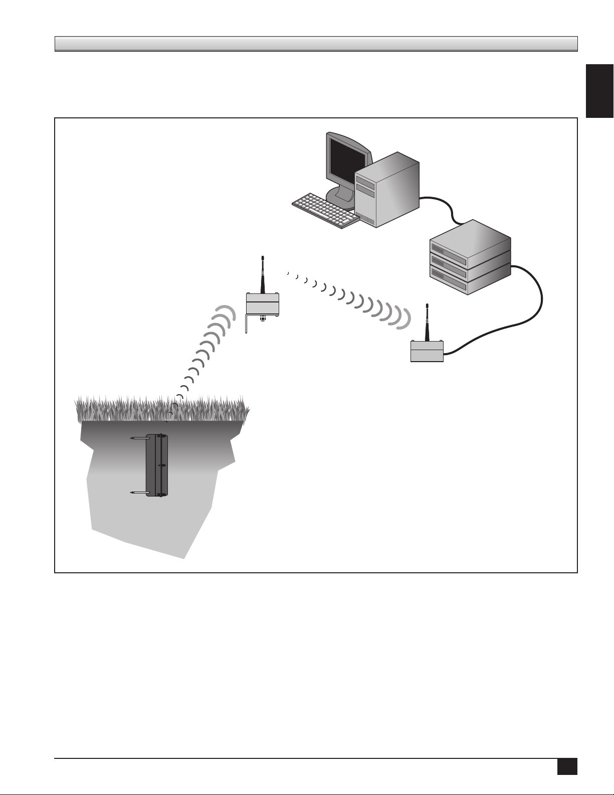
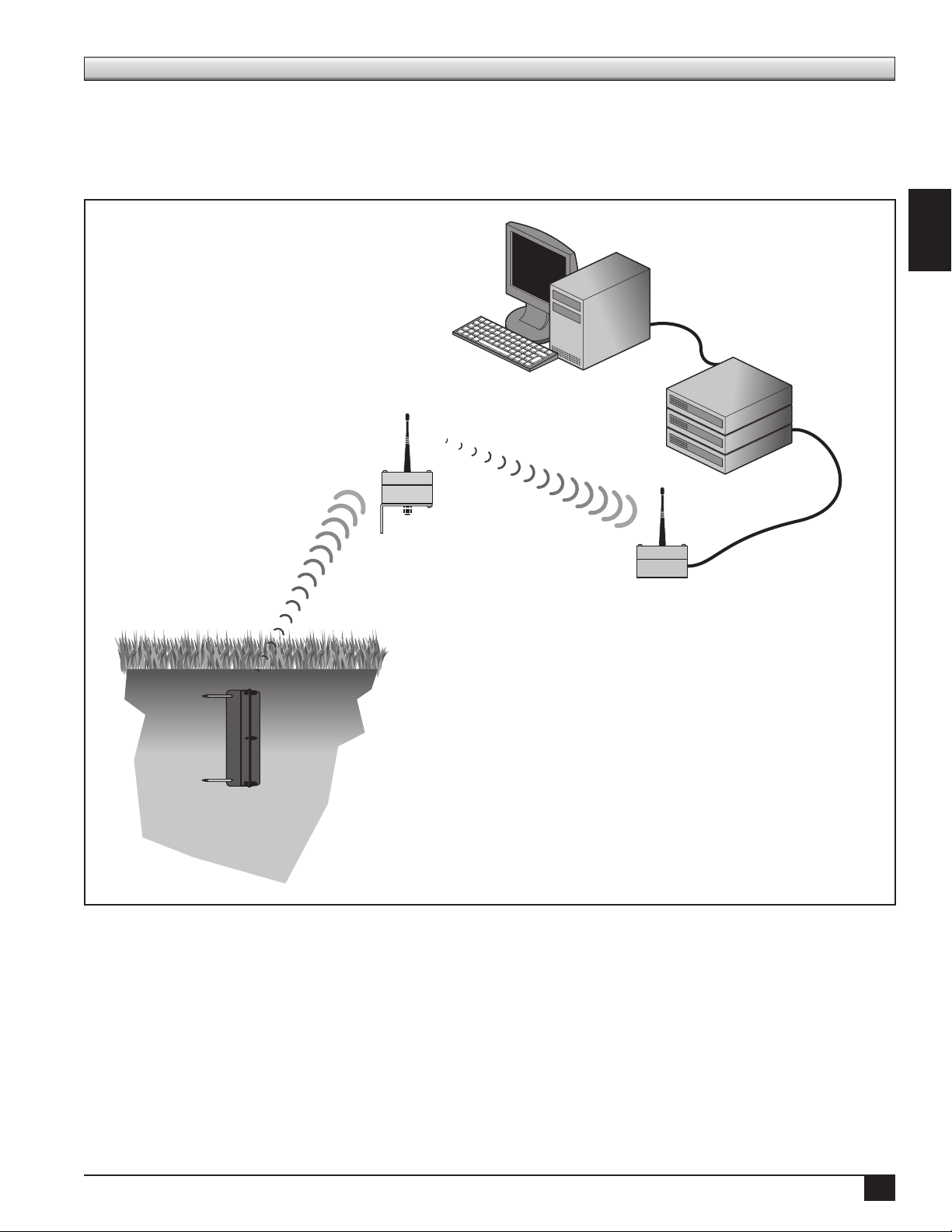
Turf Guard utilizes a communication system consisting of sensors and repeaters which relay information to
a base station, which is normally located in an oce location near the irrigation central control computer.
Utilizing Ethernet access, the base station transfers the eld sensor data to the Turf Guard server where the
information is referenced, stored, and available to the user through their existing computer.
Personal Computer
Turf Guard Server
(O site)
Repeater
English
Turf Guard
Sensor
Base Station
1
Page 4

Pre-Installation Procedures
Creating a Distributor Account
Prior to installing the Turf Guard system, you will need to set up a distributor account to access turfguard.net.
To set up the distributor account, simply e-mail the desired user name and password to tgaccount@toro.com.
Distributors may set multiple accounts as they wish (for example, one per branch, one per sales rep, etc.). You
will get an e-mail notication if the desired user name has already been taken.
Account Setup
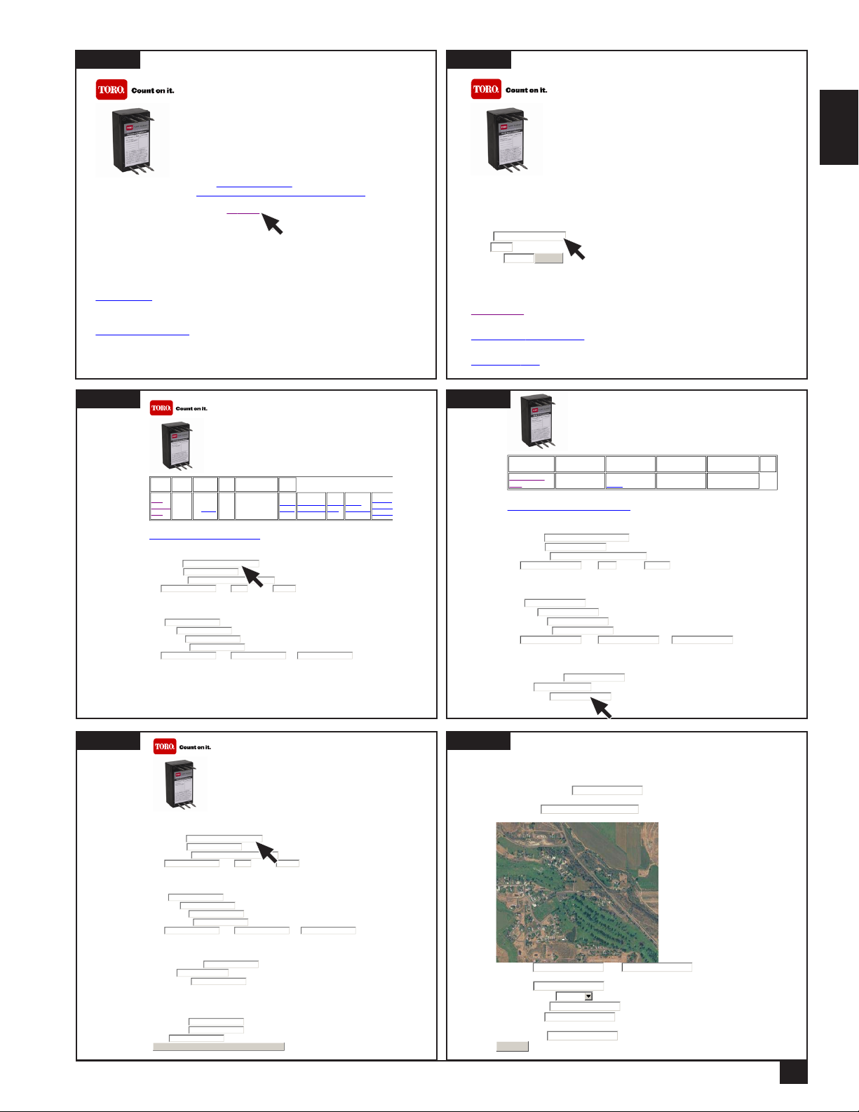
Once you have been assigned a distributor User Name and Password, you can proceed to the account setup
process. To initiate your account setup, go to install.turfguard.net (do not include www).
Step 1 Click on the Pre-Install link under the Pre-Install Worksheet header. See Figure 1.
Enter your user name and password to login.
Step 2 Search for the Course in the database by entering the Course Name, State and/or 5-digit Zip Code
where it is located. Click search to process. See Figure 2. You do not need to provide information for
all the elds to process a search. e more criteria entered in the elds, the narrower the search will be.
If the search did not return the course you are searching for, try using a more general criteria. For
example, enter “Toro” for the Course Name instead of “Toro Country Club”.
Step 3 A listing of courses that t the criteria you entered will be displayed. Select the desired course by
clicking on the Name. e course information page will open. Most of the basic information for
this course will be pre-lled. Complete the elds in the Course Information, Superintendent
Information, Turf Guard End User Information and Installation Information sections. Verify that
you enter the course address under Superintendent’s address as Toro will use this to send replacement
sensors, etc. See Figure 3.
Step 4 Each Turf Guard base station has a unique ID located on the bottom of the unit. e Turf Guard
system use this ID to route data inside its servers. Enter the ID number in the Base Station ID eld
under Turf Guard End User Information. See Figure 4. Record the base station ID in the Installation
Log under Base Station/Repeater Information.
NOTE: Each base station can only be assigned to one course, however, one course may have multiple
base stations assigned to it.
Step 5 Once all the necessary elds are loaded with correct information, click Update and Request Turf
Guard Account button to process.
If the course you are searching for is not in the database, click Add New Course. Complete the elds
in the Course Information, Superintendent Information, Turf Guard End User Information and
Installation Information sections. See Figure 5.
Once all the necessary elds are loaded with correct information, click Update and Request Turf Guard
Account button to process.
Step 6 Once Update and Request Turf Guard Account is processed, the Conrm Account Creation
window will open. Make sure the Map on this page is centered on the course and verify all information
in the elds are correct. It is particularly important to ensure that the proper time zone is selected.
Enter the desired user name and password under Turf Guard Information (user name or password can
not contain spaces). Record this information on the rst page of the Installation log. is will be used
later to access the course’s sensor data in SiteVisionTM on turfguard.net. If at any time the user name
or password needs to be changed, contact NSN at 1-800-527-4248.
2
Page 5
Page 1 of 1
N
Page 1 of 2
Figure 1
N
Page 1 of 1
N
N
Page 1 of 1
N
t
Page 1 of 2
N
Page 1 of 2
Turf Guard™ Installation Manual: click here to download
Turf Guard™ Network Tool: click here to download, save to hard drive and run
Turf Guard™ Installers toolbox:
To Turf Guard's
access this page.
To request a Turf Guard Distributor account, please send and email to tgaccount@toro.com. Include the
username and password you request.
For Sensor Activation
Install sheet.
You will find links to Comm Check and Sensor Activation next to the course list once a database has
been created.
Pre-Install Worksheet
and
More Information
You are connecting from
IP address: 170.92.64.200
Lantronix Device Install Tool
: Pre
-Install -- A Turf Guard distributor account is required to
Connectivity Check
: First search for the course in our database via the Pre-
Figure 2
Turf Guard™
Search for the course you want to install on.
Toro has a large list of courses in their database, please search for your course before adding a new
course.
Please fill in at least one field.
ame:
State: (2 letters)
Zip Code:
OR
Please search the database before adding a new course!!!
Add New Course
OR
Generate a Stand-alone Unlock Code
OR
Install the Stand-alone
search
English
Figure 3
Figure 5
Course
Name
Toro
Country
Club
Turf Guard™
Street
City,
State, Zip
Riverside,
Ca 92504
Phone
(800)
5551234
Address
1234
Club
House
Dr
Turf Guard
Course ID
ToroCountryClub
Tools
Comm
Check
Check Base
Assignment
Assign
Base
Sensor
Activation
View Sensor Placement
Course Information:
Toro Country Club
Course Name
(800) 555-1234
Course Phone
1234 Club House Dr
Course Address
Riverside Ca 92504
City State Zip Code
Superintendent Information:
John Smith
ame
(800) 555-1234
Cell Phone
john.smith@toro.com
Email Address
1234 Main St
Mailing Address
Riverside Ca 92504
City State Zip
Turf Guard End User Information:
Once the couse has been created, the username and password can be changed through NSN.
To Check the current base station assignments, please use the Check Base Assignment link above.
If you need to assign a different base station to this course, contact NSN
Turf Guard™
Course Information:
Course Name
Course Phone
Course Address
City State Zip Code
Transfer
Sensors
GolfVisi
Figure 4
Figure 6
Turf Guard™
Course Name Street Address City, State, Zip Phone
Toro Country
Club
1234 Club House DrRiverside, Ca
92504
(800) 555-1234
View Sensor Placement
Course Information:
Toro Country Club
Course Name
(800) 555-1234
Course Phone
Course Address
City State Zip Code
Superintendent Information:
Cell Phone
Email Address
Mailing Address
City State Zip
Turf Guard End User Information:
Requested Username
Password
Base Station ID (Enter 0 if you don't have a base yet)
1234 Club House Dr
Riverside Ca 92504
John Smith
ame
(800) 555-1234
john.smith@toro.com
1234 Main St
Riverside Ca 92504
JohnSmith
123
Turf Guard Course
ID
No Turf Guard Account
Confirm Account Creation:
Your Course ID will be:
Please Confirm:
Course Name:
Choose Course Lat/Lon using map: (Zoom to precise location)
ToroCountryClub
Toro Country Club
Tools
Superintendent Information:
ame
Cell Phone
Email Address
Mailing Address
City State Zip
Turf Guard End User Information:
Requested Username
Password
0
Base Station ID (Enter 0 if you don't have a base yet)
Installation Information:
Installer Name
Email Address
Phone
Update and Request Turf Guard Account
10 DigitalGlobe, GeoEye, State of Utah, USDA Farm Service Agency -
40.3091739 -110.0106943
Course Lat: Lon:
92504
Course Zip:
Course Time Zone:
ew User Name:
ew Password:
Base Station ID: (Enter 0 if you don't have a base yet)
Confirm
Eastern
JohnSmith
password
123
3
Page 6
Sensor Activation - Replaceable Battery Sensor Model
Each sensor needs to be activated by the installer BEFORE delivery to the course. e sensors are set from the factory
in a dormant state. In dormant state, the sensors either do not transmit at all or do transmit, but with a greater than
400 age interval. e sensor must be activated to initiate proper communication. is is typically done by Toro NSN
prior to shipment.
Sensor activation must be done with the sensor in close proximity of the course’s base station. Record each sensor’s ID
in the installation log on the Sensor Activation page.
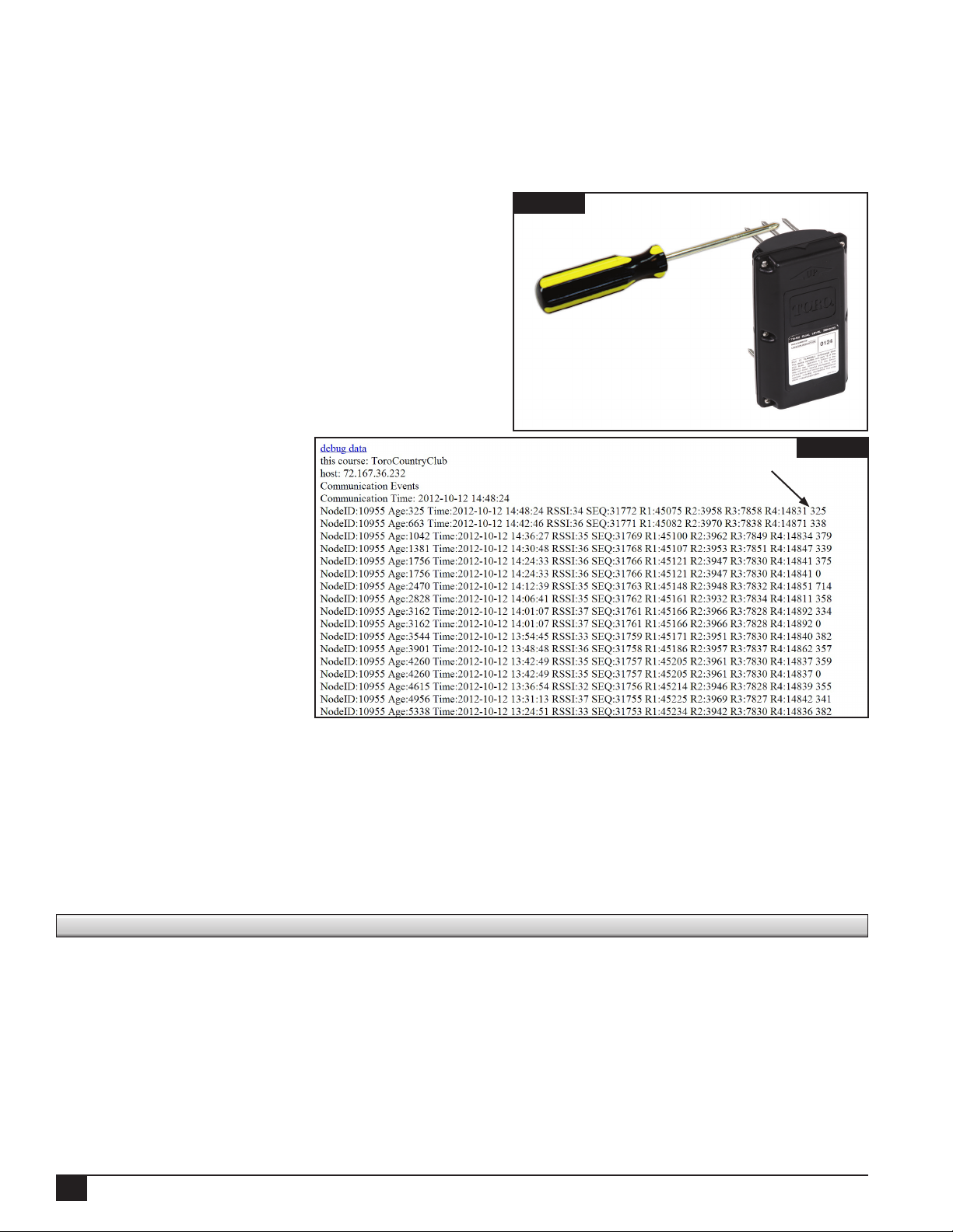
Step 1 To activate the sensor, you need a conductive material
such as a screwdriver. Place the conductive material
on the top middle spike of the sensor while touching
the other end of the conductor on any of the top
outer spikes. Hold this position for approximately 30
seconds. See Figure 9.
Step 2 Verify sensor activation. After 30 minutes, it is
possible to verify successful activation.
To verify, navigate to install.turfguard.net. Click on
the Pre-Install link under the Pre-Install Worksheet
header. Search for the Course in the database by
entering the Course
Name, State and/or 5-digit
Zip Code where it is
located. Select the course
by clicking on the name.
See Figure 3. Click on
Comm Check. See Figure
11. Look for sensor ID and
click details. Check to see
that sensor communicates
within 400 seconds by
viewing the Age at the
end of each row since the
activation. See Figure 10.
Turf Guard uses the term
“node” to refer to base
stations, repeaters and sensors. A Node ID of 0 is assigned to the base station. Repeaters have a Node ID
number of less 256. Numbers above 256 are designated for sensors.
“Age” (see screenshot above) is the time in seconds since the last communication reading. e “Age” should
remain under 400 seconds if the sensor is activated and working properly. If “Age” exceeds 1000 seconds,
the sensor is not communicating reliably and if it exceeds 2000 seconds, the sensor may not have been
activated or the battery may be drained and needs replacement.
e “MAX(RSSI)” displays the signal strength. A reading of 30 RSSI or more is considered a good signal.
CNT is a measurement of time interval or frequency.
Figure 9
Figure 10
Age number
Installation Procedures
Here is a list of recommended tools needed to have an easy and ecient Turf Guard system installation. You will need
to bring in the eld the following:
• Bucket/Keeper of the Greens • Ethernet Switch (Splitter)
• 3 Scraper Tool/Putty Knife • Tool Pack
• Turf Guard Installation Book - #2 and #3 Phillips Head Screw Driver
• Pen and Notebook for Use in Field - #2 Standard Screw Driver
• Survey Grade Tape Measure - Standard Pliers
• Ice Pick - Long Nose Pliers
• Cordless Drill w/ Screw Bits - Diagonal Cutters
- Zip Ties
4
Page 7
N
N
N
N
N
N
N
N
N
N
N
N
N
N
N
N
N
N
N
N
N
N
N
N
N
N
N
N
N
N
N
N
N
N
Page 1 of 3
Base Station Installation
e Turf Guard base station connects to the internet via an Ethernet port. Find an ideal installation location
near a high-speed internet connection. e physical
Figure 11
building location of the base station should also be
considered (i.e. basement, building with thick brick
walls) as it may decrease the range of the system. Make
sure to record
the installation location in the installation log.
Once installed, the base station connectivity can be
conrmed via the web or a web-enabled cellular phone.
Step 1 Access install.turfguard.net from your
computer. Enter your user name and password
to login.
Step 2 Click on the Pre-Install link under the
Pre-Install Worksheet header. Search for the
Course in the database by entering the Course
Name, State and/or 5-digit Zip Code where it
is located. Select the course by clicking on the
name.
Step 3 Click on the Comm Check link next to the
course’s name. See Figure 11. e base station
will have the Node ID of 0.
course: ToroCountryClub
host: dev3.turfguard.net
Communication Events
Communication Time: 2010-02-23 08:59:19
odeID:0 Age:95 MAX(RSSI):0 CNT:17 details
odeID:975 Age:275 MAX(RSSI):31 CNT:0 This sensor may not yet be activated.details
odeID:980 Age:23 MAX(RSSI):37 CNT:12 details
odeID:1124 Age:125 MAX(RSSI):31 CNT:0 This sensor may not yet be activated.details
odeID:1135 Age:169 MAX(RSSI):34 CNT:0 This sensor may not yet be activated.details
odeID:1136 Age:90 MAX(RSSI):34 CNT:0 This sensor may not yet be activated.details
odeID:1171 Age:77 MAX(RSSI):34 CNT:0 This sensor may not yet be activated.details
odeID:1174 Age:214 MAX(RSSI):32 CNT:0 This sensor may not yet be activated.details
odeID:1221 Age:188 MAX(RSSI):38 CNT:0 This sensor may not yet be activated.details
odeID:1590 Age:173 MAX(RSSI):60 CNT:0 This sensor may not yet be activated.details
odeID:1611 Age:12 MAX(RSSI):60 CNT:12 details
odeID:1617 Age:141 MAX(RSSI):36 CNT:0 This sensor may not yet be activated.details
odeID:1642 Age:104 MAX(RSSI):31 CNT:0 This sensor may not yet be activated.details
odeID:2027 Age:310 MAX(RSSI):59 CNT:0 This sensor may not yet be activated.details
odeID:2054 Age:46 MAX(RSSI):61 CNT:0 This sensor may not yet be activated.details
odeID:2064 Age:150 MAX(RSSI):45 CNT:0 This sensor may not yet be activated.details
odeID:2068 Age:264 MAX(RSSI):51 CNT:0 This sensor may not yet be activated.details
odeID:2086 Age:274 MAX(RSSI):47 CNT:0 This sensor may not yet be activated.details
odeID:2109 Age:181 MAX(RSSI):42 CNT:0 This sensor may not yet be activated.details
odeID:2142 Age:20 MAX(RSSI):60 CNT:0 This sensor may not yet be activated.details
odeID:2243 Age:193 MAX(RSSI):38 CNT:0 This sensor may not yet be activated.details
odeID:2261 Age:64 MAX(RSSI):46 CNT:0 This sensor may not yet be activated.details
odeID:2295 Age:243 MAX(RSSI):49 CNT:0 This sensor may not yet be activated.details
odeID:2296 Age:119 MAX(RSSI):49 CNT:0 This sensor may not yet be activated.details
odeID:2299 Age:204 MAX(RSSI):59 CNT:0 This sensor may not yet be activated.details
odeID:2345 Age:222 MAX(RSSI):49 CNT:0 This sensor may not yet be activated.details
odeID:2375 Age:181 MAX(RSSI):47 CNT:0 This sensor may not yet be activated.details
odeID:2377 Age:92 MAX(RSSI):59 CNT:0 This sensor may not yet be activated.details
odeID:2381 Age:199 MAX(RSSI):61 CNT:0 This sensor may not yet be activated.details
odeID:2496 Age:11 MAX(RSSI):36 CNT:0 This sensor may not yet be activated.details
odeID:2504 Age:6 MAX(RSSI):60 CNT:0 This sensor may not yet be activated.details
odeID:2530 Age:126 MAX(RSSI):48 CNT:0 This sensor may not yet be activated.details
odeID:2595 Age:222 MAX(RSSI):45 CNT:92 details
odeID:2641 Age:53 MAX(RSSI):60 CNT:0 This sensor may not yet be activated.details
NOTE: It may take up to ve minutes after the
base station is rst hooked up before it begins communicating with the web site.
English
Base Station Troubleshooting
If the base station fails to connect to the Turf Guard servers, try the following:
Step 1 Make sure the power cable is pushed into the base station all the way. Conrm power connection by
looking for two green lights on the Ethernet jack, shown in the gure to the left.
Step 2 Verify that the correct base station ID number was entered in the Creating the Customer Account
section.
Step 3 Verify internet connectivity on the computer sharing the same port as the base station.
Step 4 If none of the above work, there may be a re wall blocking communication. is re wall may have to
be re-congured to allow proper functionality of the system. Contact Toro NSN for assistance, or give
the below information (i.e. the “Technical Note”) to an IT professional so they may re-congure as
needed.
TECHNICAL NOTE: e base station expects DHCP automatic address assignment and creates an outbound
TCP/IP connection to the Turf Guard servers (Server Name: dev0.turfguard.net, dev2.turfguard.net ,
dev5.turfguard.net, dev9.turfguard.net; ports: 3389, 3399, 8080, 8081, 8888, 9080). is process generally
does not require ANY conguration. e installation tool is linked from install.turfguard.net under “Lantronix
Device Install Tool”.
For Technical Support, call NSN at 800-527-4248.
5
Page 8
Repeater Installation
e Turf Guard System communicates with the buried soil sensors via a network of above ground repeaters that
are installed on the irrigation satellite pedestals that are already on the course.
Proper repeater location is critical to the success of the Turf Guard system. It is recommended that a repeater is
located within 500' (152.4m) (line of sight) of all buried sensors. Generally, this means that a repeater will be
installed on the nearest pedestal to each green. Depending on conditions, the range can exceed 500' (152.4m).
ere are three types of repeater installation; Internal Repeater for Network VP, Internal Repeater for Nonnetwork VP and External Repeater. Repeater installation may require a Turf Guard power supply, part number
TG-PS, for power integration.
e Internal Repeater is currently set up for use with Toro Network VP, Network LTC Plus and E-OSMAC
plastic pedestal satellites only. All other satellite models will utilize the external repeater.
Install the repeaters in the pedestal locations identied by the superintendent. Make sure to record the repeater
ID and location in the installation log.
IMPORTANT: With all installation types, always shut o the power to the satellites before initiating your
installation.
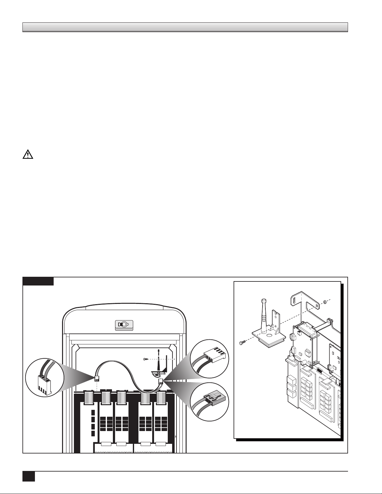
Internal Repeater Installation - Toro Network VP Satellite - Plastic Pedestal
Step 1 Turn the power source OFF to the Network VP satellite controller and remove the front plastic door.
Step 2 Locate the top threaded insert on the right, inner wall of the pedestal.
Step 3 Install the bracket using the 1/4" (6.4mm) #20 screw to the threaded insert.
Make sure the bracket is securely fastened.
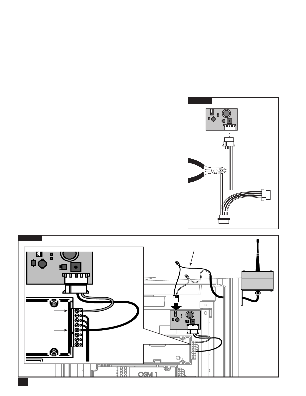
Step 4 Connect the power cable to the repeater assembly and VP distribution board 4-pin power terminal.
See Figure 12 for proper cable orientation.
Step 5 Turn the power source back ON to the VP controller and record the repeater ID and location in the
Installation log.
Figure 12
6
Page 9
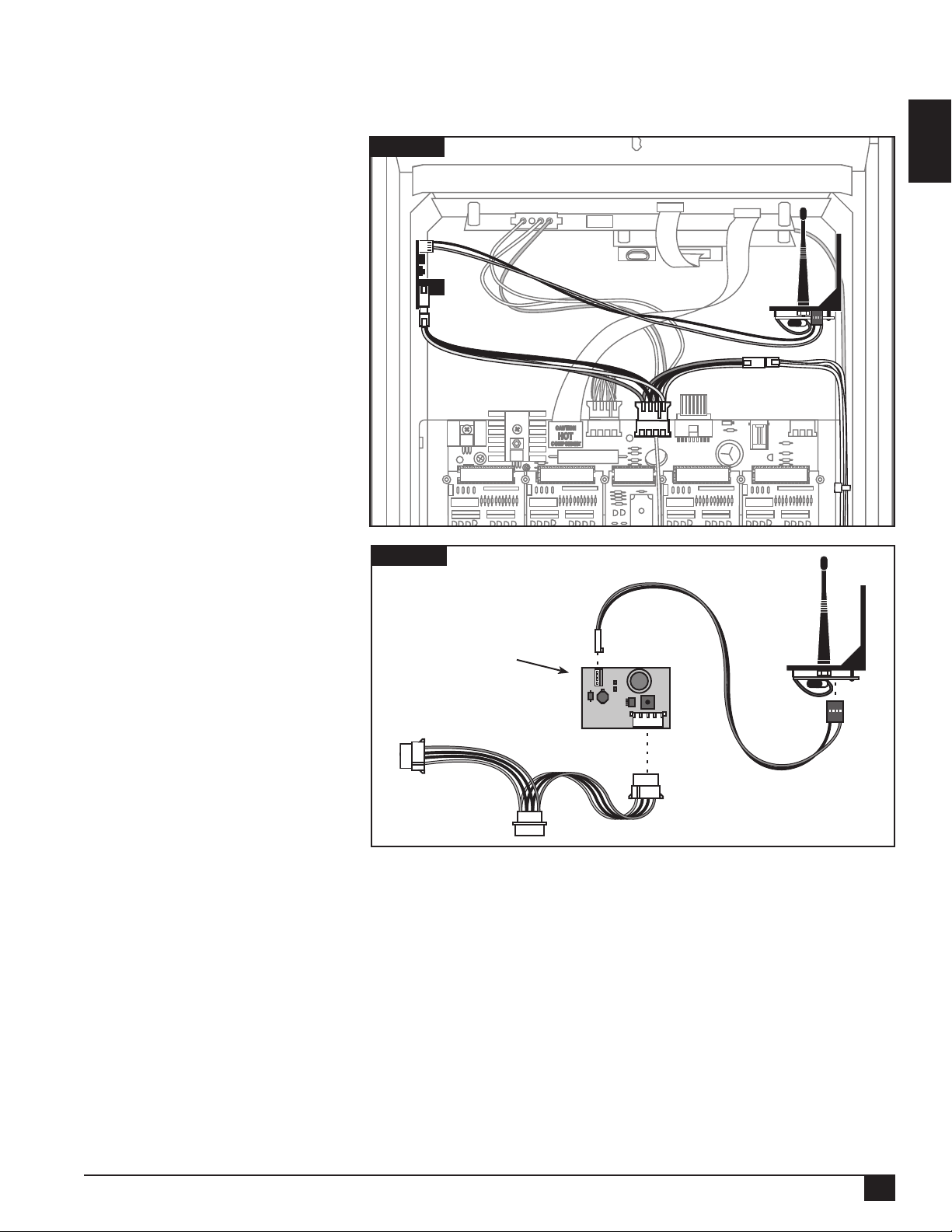
Internal Repeater Installation - Toro Network LTC Plus Satellite - Plastic Pedestal
To complete this installation, you will need an internal repeater, a power supply board (to plug into the LTC
Plus 13 VAC power supply) and a 1/4" (6.4mm) #20 x 5/8" (15.9mm) socket-head cap screw.
Step 1 Turn the power source OFF
to the Network LTC Plus
satellite controller and
remove the front plastic
door.
Step 2 Mount the repeater on the
inside wall of the pedestal
(on either side) using a
1/4" (6.4mm) #20 x 5/8"
(15.9mm) socket-head cap
screw.
Step 3 Mount the power conversion
board on the inside of
the satellite opposite the
repeater using the adhesive
back. See Figure 13.
Step 4 Connect the power supply
board (TG-PS) to the power
source. See Figure 14.
Step 5 Connect the power
conversion board to the
repeater using the power
connector cable.
Step 6 Turn the power source back
ON to the satellite.
Figure 13
Figure 14
Power Supply Board
(TG-PS)
English
Repeater
Step 7 Record the repeater ID and
location in the Installation
Log.
Step 8 Proceed to the Internal
Repeater Startup Procedure
section.
To Circuit Board
To Power Cable
7
Page 10
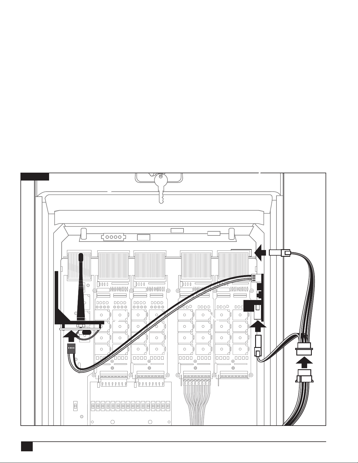
Internal Repeater Installation - Toro E-OSMAC Satellite - Plastic Pedestal
To complete this installation, you will need an internal repeater, a power conversion board (to tie into the
E-OSMAC’s 13 VAC power supply), and a 3/4" (19mm) #10 sheet metal screw.
Step 1 Turn the power source OFF to the E-OSMAC satellite controller and remove the front plastic door.
Step 2 Detach the top circuit board. See Figure 15.
Step 3 Connect the power conversion board to the power source.
Step 4 Reattach the circuit board.
Step 5 Mount the conversion board on the inside wall of the pedestal using the adhesive back.
Step 6 Mount the repeater on the inside wall opposite the conversion board using a 3/4" (19mm)
#10 sheet metal screw.
Step 7 Connect the repeater to the conversion board.
Step 8 Turn the power source back ON to the satellite.
Step 9 Record the repeater ID and location in the Installation Log.
Step 10 Proceed to the Internal Repeater Startup Procedure section.
Figure 15
8
Page 11
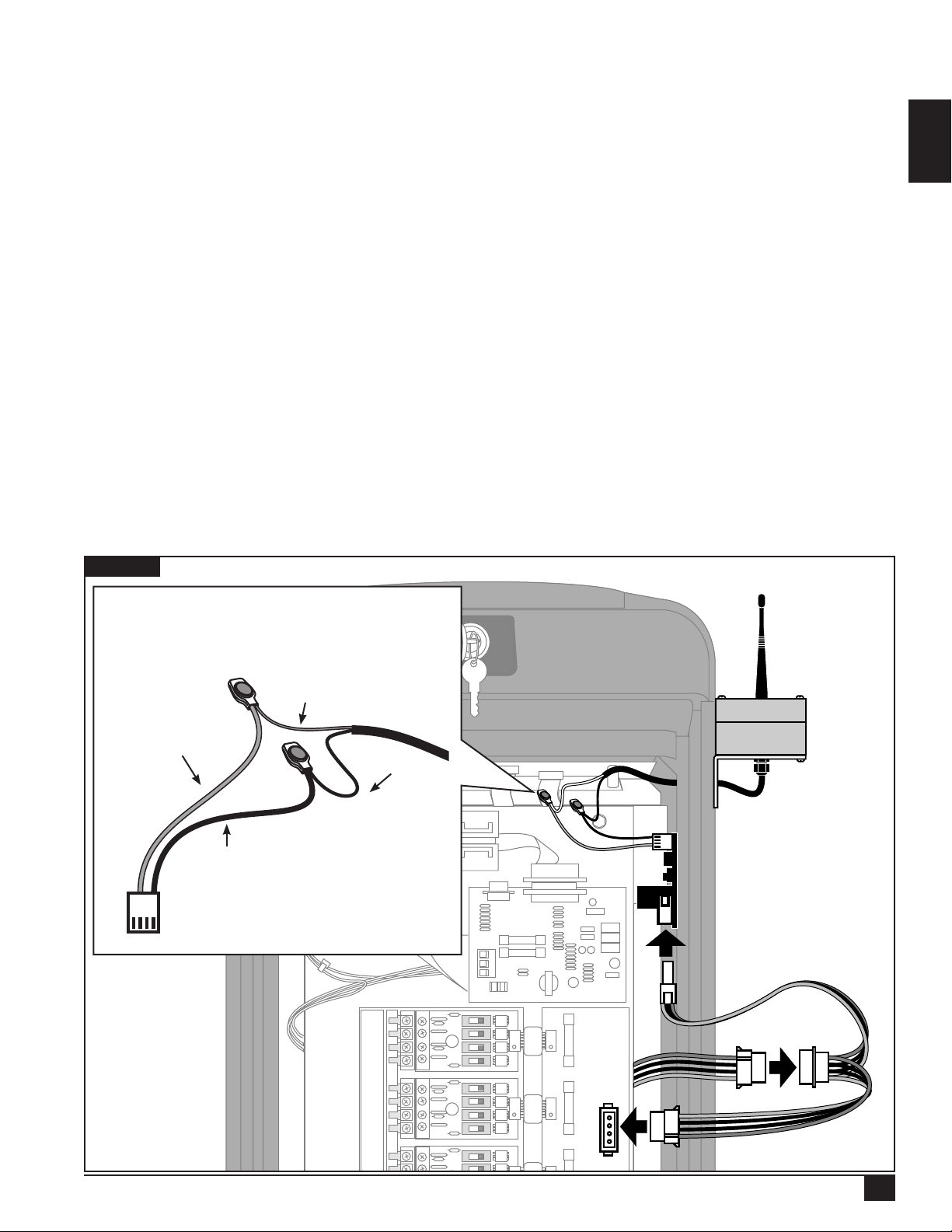
External Repeater Installation - Toro Network 8000 Satellite - Plastic Pedestal
To complete this installation, you will need an EXTERNAL repeater, a power conversion board, and two 3/4"
(19mm) #10 sheet metal screws.
Step 1 Turn the power source OFF to the Network 8000 satellite controller and remove the front plastic door.
Step 2 Mount the power conversion board on the inside wall of the pedestal using the adhesive back.
Step 3 Mount the repeater on the outside wall of the pedestal using two 3/4" (19mm) #10 sheet metal screws.
Step 4 Using a 1/4" (6.4mm) drill bit or larger, drill a hole through the sidewall of the pedestal and pull the
repeater cable through to the inside.
Step 5
Strip the end of the cable coming from the repeater so an inch or more of the two wires inside is exposed.
Step 6 Locate the power connector cable (the cable that would otherwise connect the power conversion board to
an internal repeater) and cut one end just below the white plug, cutting both black and red wires.
Step 7 Using pliers and two of the splice connectors provided, splice the cables together, as shown in
Figure 16. e red wire on the power connector cable attaches to the white wire on the repeater cable
and the black wire connects to the black wire.
Step 8 Connect the power supply board in the same way as was done in the LTC Plus installation.
Step 9 Seal all the remaining holes in the pedestal with sealing tape and/or foam gaskets.
Step 10 Turn the power source back ON to the satellite.
Step 11 Record the repeater ID and location in the Installation Log.
Figure 16
e red power wire is
connected to the white repeater
wire.
English
Red
White
Black
Black
e black power wire is
connected to the black
repeater wire.
STA 1
STA 2
STA 3
STA 4
STA 5
STA 6
STA 7
STA 8
STA 9
9
Page 12
External Repeater Installation - Rain Bird Par+ Satellite - Plastic Pedestal
To complete this installation, you will need an EXTERNAL repeater, a power conversion board (to tie into the unit’s 24
VAC power supply), and two 3/4" (19mm) #10 sheet metal screws.
e conversion board will rst have to be modied before it can be installed: you will need to cut the red and black wires
just before the rst plug. en cut the yellow and other black wire from the board as shown in Figure 17.
Step 1 Turn the power source OFF to the Rain Bird Par+ satellite controller and remove the front plastic door.
Step 2 Mount the conversion board on the front of the satellite using the adhesive back. Older Rain Bird models
may require attaching the power conversion board in a dierent location due to space constraints – NEVER
MOUNT THE POWER CONVERSION BOARD TO THE OUTSIDE OF THE PEDESTAL.
Step 3 Cut the 3-plug cable assembly as shown in Figure 17. Connect the red wire running from the conversion board
to terminal 8 labeled Valve Hot. Connect the black wire to any of the open common slots (terminals 1–5).
See Figure 18.
Step 4 Mount the repeater on the side of the pedestal using two 3/4"
(19mm) #10 sheet metal.
Step 5 Using a 1/4" (6.4mm) drill bit or larger, drill a hole through the sidewall
of the pedestal and pull the repeater cable through to the inside.
Step 6 Strip the end of this repeater cable so an inch or more of the
two wires inside is exposed.
Step 7 Next, locate the power connector cable (the cable that would
otherwise connect the power conversion board to an internal
repeater) and cut one end just below the white plug, cutting
both black and red wires.
Step 8 Using pliers and two of the splice connectors provided, splice the
cables together, as shown in Figure 16. e red wire on the power
connector cable attaches to the white wire on the repeater cable and
the black wire connects to the black wire.
Step 9 Seal all the remaining holes in the pedestal with sealing tape
and/or foam gaskets. e repeater is now connected to a
24 VAC power supply.
Step 10 Turn the power source back ON to satellite.
Step 11 Record the repeater ID and location in the Installation Log.
Figure 17
Figure 18
Red Wire
Black Wire
10
See Figure 16 for details.
Page 13
External Repeater Installation - Metal Pedestal Satellites
For all stainless steel pedestals, attach the external repeater to the outside of the unit as in the Rain Bird Par+
installation Figure 17 and Figure 18. Once the repeater cable has been pulled through to the inside of the
unit, installation will be the same as on the plastic model equivalent (the internal components of the plastic and
stainless steel models are identical). Note that unlike on the plastic pedestals, however, the screw holes will need
to be pre-drilled into the pedestal wall before mounting the external repeater.
Internal Repeater Start-up Procedure
On the initial power up of the repeater, all three lights located on the repeater’s circuit board should illuminate
steadily. After approximately 10 seconds, the repeater will begin searching for a network. As it searches, the inboard
light should ash at a rate of about once per second. If the repeater nds a network, the light will begin ashing
faster (about twice per second) BEFORE THE COUNT OF SLOW FLASHES REACHES FIFTY FLASHES.
If the count of slow ashes reaches fty ashes, the repeater has failed to nd the network. In the event that
this should happen, the installer can initiate a new search by powering down the repeater for approximately one
minute (or until all three lights cease to be illuminated). e repeater can then be powered up again for another
search. If the repeater still cannot nd the network after several attempts, it is considered “out of range” and
must be moved to a site that is closer to the base station or an adjacent repeater.
Sensor Installation
e TG-S2 Dual-level Sensor measures temperature, moisture and salt content at two distinct depths in the
soil prole—approximately 2"–7" (5–17.8cm) below grade. e six stainless steel probes produce independent
measurements of moisture, salinity, and temperature at each depth.
English
e sensor should be located in an area that best represents the turf conditions including overall health/disease,
salinity build-up, wet/dry spots and foot trac. For greens applications, avoid cup placement locations.
Once the sensor installation site is determined, record its exact location using xed landmarks or GPS coordinates
(if available). In addition, note the sensor identication number or address, as indicated on the Turf Guard placard.
NOTE: If necessary, a metal detector can also be used to locate buried sensors.
Installation Procedure
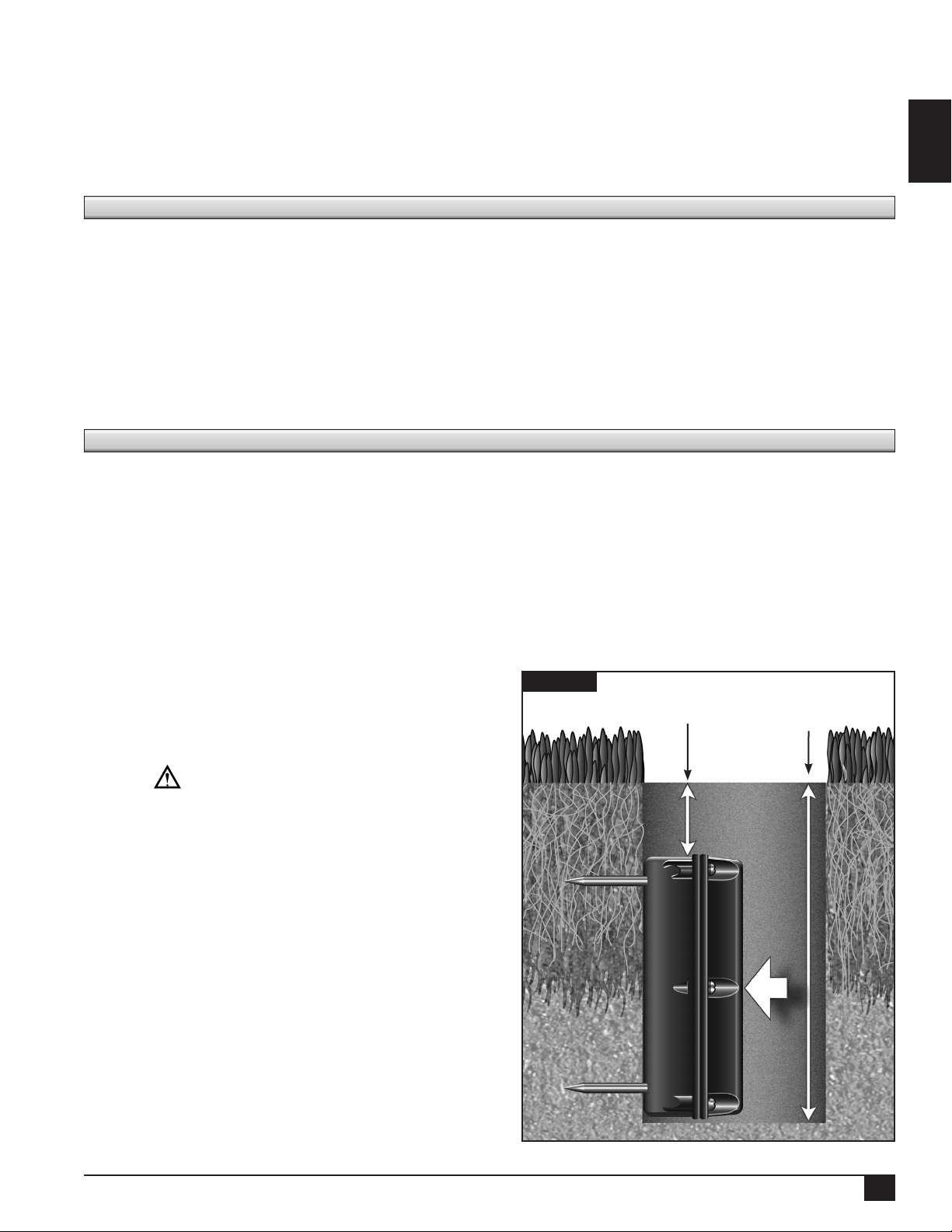
Step 1 Using a standard greens cup cutter, remove a turf
Figure 19
plug and soil to a depth of about 8" (20.3cm).
Retain the turf plug to replace over the installed
2" (5cm)
Maximum Buried
Depth
8" (20.3cm) Hole
Depth
sensor.
IMPORTANT: e sensor’s internal antenna
is located near the top of the housing (identied
by the UP arrow). Installing the sensor upside
down can greatly impair signal or prevent wireless
communication altogether.
Step 2 With the sensor oriented correctly, place it carefully
into the hole to prevent scraping or disrupting the
soil compaction with the spiked probes.
Step 3 Position the top of the sensor no more than 2"
(5cm) below grade. Press the sensor laterally
against the side of the hole, inserting the probes
completely into the soil
Step 4 Carefully back ll and compact soil or greens mix
around and under the sensor to prevent voids and/
or movement of the sensor.
Step 5 Replace the turf plug, blending the seam with the
surrounding turf.
NOTE: For replacement battery, contact your Toro
distributor.
11
Page 14
Locating Buried Sensors
If at some point a sensor needs to be removed, the following procedure is recommended for locating it. is
process is also recommended for agging sensors before aeration, allowing maintenance workers to aerate around
them. Toro recommends using White’s PRL-1 metal detector from White’s Electronics for both of these tasks.
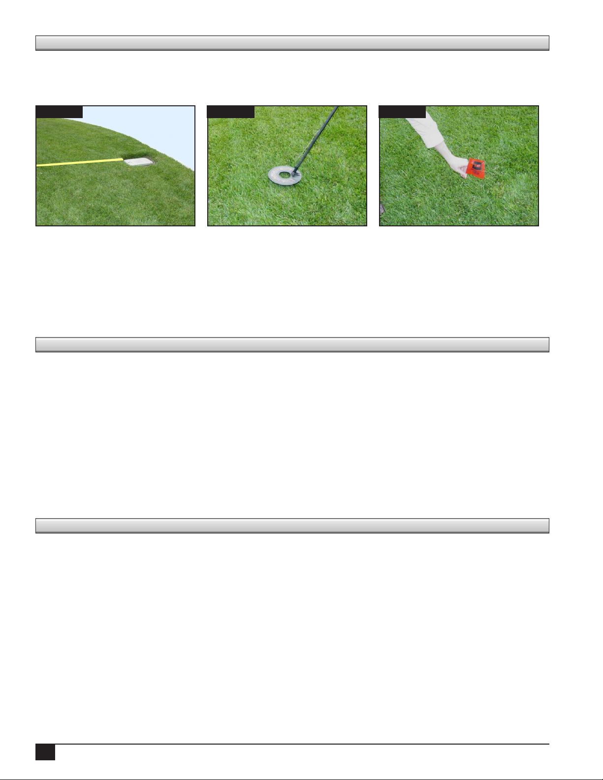
Figure 21Figure 20 Figure 22
Step 1 Check the recorded distances from sensors to landmarks in either the Installation Log or on the printed
sensor location maps. Use these measurements to nd the approximate area in the eld. See Figure 20.
Step 2 Use the PRL-1 metal detector to close in on the exact sensor location. For best results, set the detector’s
sensitivity dial to Ring. See Figure 21.
Step 3 Remove the sensor, or if aerating, place a ag directly above the sensor until aeration is complete.
See Figure 22.
Superintendent Training
When nished with the installation, it’s important to walk the superintendent through the key Turf Guard tasks.
is should be done on-site. Since the newly-installed sensors will need approximately 24 hours to provide stable
data, instead of logging in to SiteVision on turfguard.net with the course account, log in using the demo account
(user name: toro_guest, password: demo).
Explain the various functions of the web site (for example, moisture levels, temperature, salinity levels, and
running reports). Make sure to also discuss aeration procedures with the superintendent, as well as demonstrate
how to locate sensors using a metal detector (see the Locating Buried Sensors section at the end of this manual).
Make sure you also follow-up with the superintendent by phone within 24 to 48 hours after the installation.
Verify system operation at turfguard.net and answer any questions the superintendent may have. It’s also
recommended that a training “refresher” be conducted on-site seven to ten days after the installation. Present
the superintendent with the Installation Log and the printed sensor location maps, and explain NSN’s 5-year
extended support plan.
Specifications
Base Station
Operating Voltage: 6 VDC, Level 4, Certied Power Supply (6 VDC, Max 2.5A)
Operating Temperature: 32˚–130˚F (0˚–54˚C)
Humidity: 90% Maximum
Repeater
Operating Voltage: 6 VDC, Level 4, Certied Power Supply )6 VDC, Max 2.5A)
Operating Temperature: 32˚–130˚F (0˚–54˚C)
Humidity: 90% Maximum
Sensor
Operating Voltage: 4.5 VDC, Alkaline
Operating Temperature: 32˚–130˚F (0˚–54˚C)
Humidity: 90% Maximum
12
Page 15

Notes
English
13
Page 16

Contenido
Descripción del Sistema 15
Procedimiento de preinstalación 16
Creación de la cuenta del distribuidor 16
Conguración de la cuenta 16
Activación de sensores 18
Procedimientos de instalación 18
Instalación de la estación base 19
Instalación 19
Solución de Problemas 19
Instalación de repetidores 20
Instalación de un repetidor interno - Satélite Network VP de Toro - Pedestal de plástico 20
Instalación de un repetidor interno - Satélite Network LTC Plus de Toro- Pedestal de plástico 21
Instalación de un repetidor interno - Satélite E-OSMAC de Toro - Pedestal de plástico 22
Instalación de un repetidor externo - Satélite Network 8000 de Toro - Pedestal de plástico 23
Instalación de un repetidor externo - Satélite Rain Bird Par+ - Pedestal de plástico 24
Instalación de un repetidor externo - Satélites de pedestal metálico 25
Procedimiento de arranque del repetidor interno 25
Instalación del sensor 25
Localización de sensores enterrados 26
Formación de Superintendentes 26
xiv
Page 17
Descripción del Sistema
Turf Guard utiliza un sistema de comunicación que consiste en sensores y repetidores que envían información
a una estación base – normalmente situada en un ocina cerca del ordenador de control central de riego.
Utilizando acceso por Ethernet, la estación base transere los datos desde el sensor de campo al servidor Turf
Guard donde la información es referenciada y almacenada, y queda disponible para el usuario a través de su
ordenador.
Ordenador personal
Servidor Turf Guard
(Fuera del campo)
Repetidor
Español
Sensor Turf
Guard
Estación base
15
Page 18

Procedimientos de Preinstalación
Creación de la cuenta del distribuidor
Antes de instalar el sistema Turf Guard, será necesario congurar una cuenta de distribuidor para acceder a
turfguard.net. Para congurar la cuenta del distribuidor, simplemente envíe por e-mail el nombre de usuario y
contraseña deseados a tgaccount@toro.com. Los distribuidores puede establecer múltiples cuentas según deseen
(por ejemplo, una por delegación, una por representante de ventas, etc.). Recibirá una noticación por correo
electrónico si el nombre de usuario deseado ya está asignado.
Conguración de la cuenta
Una vez que le hayan asignado un nombre de usuario y contraseña, puede continuar con el proceso de conguración
de la cuenta. Para iniciar la conguración de su cuenta, vaya a install.turfguard.net (no incluya ‘www’).
Paso 1 Haga clic en el enlace Pre-Install (Preinstalación) del apartado Hoja de cálculo de preinstalación. Ver
la Figura 1. Introduzca su nombre de usuario y contraseña para conectarse.
Paso 2 Busque el Campo en la base de datos, introduciendo el Nombre del campo, Estado y/o el Código
Zip de 5 dígitos del campo. Haga clic en buscar (search) para continuar. Ver la Figura 2. No necesita
introducir información en todos los campos para procesar la búsqueda. Cuantos más criterios se
introduzcan en los campos, más enfocada será la búsqueda.
Si la búsqueda no encuentra el campo que busca, pruebe usando criterios más generales. Por ejemplo,
introduzca “Toro” en Nombre del Campo en lugar de “Toro Country Club”.
Paso 3 Se muestra un listado de campos que coinciden con los criterios introducidos. Seleccione el campo
deseado haciendo clic en el nombre. Se abre la página de información del campo. La mayor parte
de la información básica de este campo ya estará introducida. Complete los campos de las secciones
Información del campo, Información del superintendente, Información del usuario nal de Turf
Guard e Información de la instalación. Debe introducir la dirección del campo en ‘Dirección del
Superintendente’, porque Toro utilizará esta dirección para enviar sensores de repuesto, etc. Ver la
Figura 3.
Paso 4 Cada estación base Turf Guard tiene un ID exclusivo, indicado en la base de la unidad. El sistema
Turf Guard utiliza este identicador para enrutar datos dentro de sus servidores. Introduzca el ID en
el campo ID de la estación base, en la sección Información del usuario nal de Turf Guard. Ver la
Figura 4. Anote el ID de la estación base en el Registro de la Instalación de la sección Información
de la Estación base/Repetidor.
NOTA: Cada estación base sólo puede asignarse a un único campo de golf; no obstante, un campo
puede tener asignadas varias estaciones base.
Paso 5 Cuando todos los campos necesarios hayan sido rellenados correctamente, haga clic en Update and
Request Turf Guard Account (Actualizar y solicitar cuenta Turf Guard).
Si el campo que busca no está en la base de datos, haga clic en Add New Course (Añadir
nuevo campo). Complete los campos de las secciones Información del campo, Información del
superintendente, Información del usuario nal de Turf Guard e Información de la instalación. Ver la
Figura 5.
Cuando todos los campos necesarios hayan sido rellenados correctamente, haga clic en Actualizar y
solicitar cuenta Turf Guard.
Paso 6 Una vez que se haya procesado Actualizar y solicitar cuenta Turf Guard, se abrirá la ventana
Conrmar creación de cuenta. Asegúrese de que el mapa de esta página quede centrado en el campo,
y compruebe que los datos de los campos son correctos. Es especialmente importante asegurar que ha
seleccionado la zona horaria correcta.
Introduzca el nombre de usuario y contraseña deseados en Información de Turf Guard (el nombre de
usuario y la contraseña no pueden contener espacios). Anote esta información en la primera página
del Registro de la Instalación. Se utilizará más adelante para acceder a los datos de los sensores del
campo en SitevisionTM en turfguard.net. Si en cualquier momento es necesario cambiar el nombre
del usuario o la contraseña, diríjase a NSN al 1-800-527-4248.
16
Page 19

Page 1 of 1
N
Page 1 of 2
Figura 1
N
Page 1 of 1
N
N
Page 1 of 1
N
t
Page 1 of 2
N
Page 1 of 2
Figura 2
Turf Guard™ Installation Manual: click here to download
Turf Guard™ Network Tool: click here to download, save to hard drive and run
Turf Guard™ Installers toolbox:
To Turf Guard's
access this page.
To request a Turf Guard Distributor account, please send and email to tgaccount@toro.com. Include the
username and password you request.
For Sensor Activation
Install sheet.
You will find links to Comm Check and Sensor Activation next to the course list once a database has
been created.
Pre-Install Worksheet
and
: Pre
-Install -- A Turf Guard distributor account is required to
Connectivity Check
: First search for the course in our database via the Pre-
More Information
You are connecting from
IP address: 170.92.64.200
Lantronix Device Install Tool
Figura 3
Course
Name
Toro
Country
Club
View Sensor Placement
Course Information:
Course Name
Course Phone
Course Address
Riverside Ca 92504
City State Zip Code
Superintendent Information:
ame
Cell Phone
Email Address
Mailing Address
Riverside Ca 92504
City State Zip
Turf Guard End User Information:
Once the couse has been created, the username and password can be changed through NSN.
To Check the current base station assignments, please use the Check Base Assignment link above.
If you need to assign a different base station to this course, contact NSN
Turf Guard™
Street
City,
Address
State, Zip
1234
Riverside,
Club
Ca 92504
House
Dr
Toro Country Club
(800) 555-1234
1234 Club House Dr
John Smith
(800) 555-1234
john.smith@toro.com
1234 Main St
Phone
(800)
5551234
Turf Guard
Course ID
ToroCountryClub
Tools
Comm
Check
Check Base
Assignment
Assign
Base
Sensor
Activation
Transfer
Sensors
GolfVisi
Turf Guard™
Search for the course you want to install on.
Toro has a large list of courses in their database, please search for your course before adding a new
course.
Please fill in at least one field.
ame:
State: (2 letters)
Zip Code:
OR
Please search the database before adding a new course!!!
Add New Course
OR
Generate a Stand-alone Unlock Code
OR
Install the Stand-alone
Figura 4
search
Turf Guard™
Course Name Street Address City, State, Zip Phone
Toro Country
Club
1234 Club House DrRiverside, Ca
92504
(800) 555-1234
View Sensor Placement
Course Information:
Toro Country Club
Course Name
(800) 555-1234
Course Phone
Course Address
City State Zip Code
Superintendent Information:
Cell Phone
Email Address
Mailing Address
City State Zip
Turf Guard End User Information:
Requested Username
Password
Base Station ID (Enter 0 if you don't have a base yet)
1234 Club House Dr
Riverside Ca 92504
John Smith
ame
(800) 555-1234
john.smith@toro.com
1234 Main St
Riverside Ca 92504
JohnSmith
123
Turf Guard Course
ID
No Turf Guard Account
Español
Tools
Figura 6
Confirm Account Creation:
Your Course ID will be:
Please Confirm:
Course Name:
Choose Course Lat/Lon using map: (Zoom to precise location)
10 DigitalGlobe, GeoEye, State of Utah, USDA Farm Service Agency -
Course Lat: Lon:
Course Zip:
Course Time Zone:
ew User Name:
ew Password:
Base Station ID: (Enter 0 if you don't have a base yet)
Confirm
ToroCountryClub
Toro Country Club
40.3091739 -110.0106943
92504
Eastern
JohnSmith
password
123
Figura 5
Turf Guard™
Course Information:
Course Name
Course Phone
Course Address
City State Zip Code
Superintendent Information:
ame
Cell Phone
Email Address
Mailing Address
City State Zip
Turf Guard End User Information:
Requested Username
Password
0
Base Station ID (Enter 0 if you don't have a base yet)
Installation Information:
Installer Name
Email Address
Phone
Update and Request Turf Guard Account
17
Page 20

Activación de sensores - Modelo de sensor de batería reemplazable
Cada sensor debe ser activado por el instalador ANTES DE su envío al campo. Los sensores se ajustan en fábrica al estado
de standby. En el estado de standby, los sensores o bien no transmiten datos, o bien transmiten únicamente datos con edad
superior a 400. El sensor debe ser activado para iniciar correctamente las comunicaciones. Este paso lo suele realizar Toro
NSN antes de suministrar el equipo.
La activación del sensor debe realizarse con el sensor en estrecha proximidad de la estación base del campo. Anote el ID de
cada sensor en el Registro de la Instalación de la página Activación
de Sensores.
Paso 1 Para activar el sensor, necesita un material conductivo
como un destornillador. Coloque el material conductivo
encima de la punta central superior del sensor y toque
una de las puntas exteriores de la la superior con el
otro extremo del conductor. Mantenga esta posición
durante aproximadamente 30 segundos.Ver la Figura 9.
Paso 2 Vericación de la activación del sensor. Después de 30
minutos, es posible vericar el éxito de la activación.
Para vericarlo, vaya a install.turfguard.net. Haga clic
en el enlace Pre-Install (Preinstalación) del apartado
Hoja de cálculo de preinstalación. Busque el Campo en
la base de datos, introduciendo el Nombre del campo,
Estado y/o el código Zip de 5 dígitos del campo. Seleccione el campo haciendo clic en el nombre. Ver la Figura 3.
Haga clic en Comm Check (Comprobación de comunicaciones). Ver la Figura 11. Busque Sensor ID y haga clic
en details (detalles). Compruebe que el sensor inicia la comunicación en 400 segundos o menos inspeccionando el
campo Edad al nal de cada
la desde la activación. Ver la
Figura 10.
Turf Guard utiliza el
término “nodo” en
referencia a las estaciones
base, los repetidores y los
sensores. Se asigna un ID
de Nodo de 0 a la estación
base. Los repetidores tienen
ID de Nodo de menos
de 256. Los números por
encima del 256 están
reservados a los sensores.
La “Edad” (ver imagen
de pantalla) es el tiempo en segundos desde la última comunicación registrada. La “Edad” debe ser siempre
de menos de 400 segundos si el sensor está activado y funciona correctamente. Si la “Edad” supera los 1000
segundos, el sensor no se comunica de manera able y si supera los 2000 segundos, es posible que el sensor no se
haya activado o la batería puede estar agotada, en cuyo caso habrá que cambiarla.
“MAX(RSSI)” muestra la potencia de la señal. Una lectura de 30 RSSI o más se considera una señal buena.
CNT es una medida del intervalo de tiempo o frecuencia.
Figura 9
Figure 10
La “Edad” nmero
Procedimientos de instalación
A continuación se ofrece una lista de herramientas recomendadas que se necesitan para efectuar la instalación de Turf
Guard de manera sencilla y eciente. Necesitará llevar al campo los siguientes artículos:
• Cubo/Keeper of the Greens™ • Switch Ethernet (splitter)
• Rascador triple/espátula estrecha • Caja de herramientas
• Libro de instalación Turf Guard - Destornillador Phillips Nº 2 y Nº 3
• Cuaderno y bolígrafo - Destornillador estándar Nº 2
• Cinta métrica de topógrafo - Alicate estándar
• Pico de hielo - Alicate de punta na
• Taladradora inalámbrica con brocas helicoidales - Alicate de corte diagonal
- Bridas
18
Page 21

N
N
N
N
N
N
N
N
N
N
N
N
N
N
N
N
N
N
N
N
N
N
N
N
N
N
N
N
N
N
N
N
N
N
Page 1 of 3
Instalación de la estación base
La estación base Turf Guard se conecta a Internet a través
de un puerto Ethernet. Busque un lugar de instalación
ideal cerca de una conexión de Internet de alta velocidad.
También debe pensar en la ubicación física de la estación
base dentro del edicio (por ejemplo, sótano, muros
gruesos de ladrillo) ya que esto puede reducir el alcance
del sistema. Anote el lugar de instalación en el Registro
de la Instalación.
Una vez instalada, puede conrmarse la conectividad
de la estación base vía Internet o a través de un teléfono
móvil con acceso a Internet.
Paso 1 Acceda a install.turfguard.net desde su
ordenador. Introduzca su nombre de usuario y
contraseña para conectarse.
Paso 2 Haga clic en el enlace Preinstalación (Pre-Install)
del apartado Hoja de cálculo de preinstalación.
Busque el campo en la base de datos,
introduciendo el Nombre del campo, Estado
y/o el código Zip de 5 dígitos del campo.
Seleccione el campo haciendo clic en el nombre.
Figura 11
course: ToroCountryClub
host: dev3.turfguard.net
Communication Events
Communication Time: 2010-02-23 08:59:19
odeID:0 Age:95 MAX(RSSI):0 CNT:17 details
odeID:975 Age:275 MAX(RSSI):31 CNT:0 This sensor may not yet be activated.details
odeID:980 Age:23 MAX(RSSI):37 CNT:12 details
odeID:1124 Age:125 MAX(RSSI):31 CNT:0 This sensor may not yet be activated.details
odeID:1135 Age:169 MAX(RSSI):34 CNT:0 This sensor may not yet be activated.details
odeID:1136 Age:90 MAX(RSSI):34 CNT:0 This sensor may not yet be activated.details
odeID:1171 Age:77 MAX(RSSI):34 CNT:0 This sensor may not yet be activated.details
odeID:1174 Age:214 MAX(RSSI):32 CNT:0 This sensor may not yet be activated.details
odeID:1221 Age:188 MAX(RSSI):38 CNT:0 This sensor may not yet be activated.details
odeID:1590 Age:173 MAX(RSSI):60 CNT:0 This sensor may not yet be activated.details
odeID:1611 Age:12 MAX(RSSI):60 CNT:12 details
odeID:1617 Age:141 MAX(RSSI):36 CNT:0 This sensor may not yet be activated.details
odeID:1642 Age:104 MAX(RSSI):31 CNT:0 This sensor may not yet be activated.details
odeID:2027 Age:310 MAX(RSSI):59 CNT:0 This sensor may not yet be activated.details
odeID:2054 Age:46 MAX(RSSI):61 CNT:0 This sensor may not yet be activated.details
odeID:2064 Age:150 MAX(RSSI):45 CNT:0 This sensor may not yet be activated.details
odeID:2068 Age:264 MAX(RSSI):51 CNT:0 This sensor may not yet be activated.details
odeID:2086 Age:274 MAX(RSSI):47 CNT:0 This sensor may not yet be activated.details
odeID:2109 Age:181 MAX(RSSI):42 CNT:0 This sensor may not yet be activated.details
odeID:2142 Age:20 MAX(RSSI):60 CNT:0 This sensor may not yet be activated.details
odeID:2243 Age:193 MAX(RSSI):38 CNT:0 This sensor may not yet be activated.details
odeID:2261 Age:64 MAX(RSSI):46 CNT:0 This sensor may not yet be activated.details
odeID:2295 Age:243 MAX(RSSI):49 CNT:0 This sensor may not yet be activated.details
odeID:2296 Age:119 MAX(RSSI):49 CNT:0 This sensor may not yet be activated.details
odeID:2299 Age:204 MAX(RSSI):59 CNT:0 This sensor may not yet be activated.details
odeID:2345 Age:222 MAX(RSSI):49 CNT:0 This sensor may not yet be activated.details
odeID:2375 Age:181 MAX(RSSI):47 CNT:0 This sensor may not yet be activated.details
odeID:2377 Age:92 MAX(RSSI):59 CNT:0 This sensor may not yet be activated.details
odeID:2381 Age:199 MAX(RSSI):61 CNT:0 This sensor may not yet be activated.details
odeID:2496 Age:11 MAX(RSSI):36 CNT:0 This sensor may not yet be activated.details
odeID:2504 Age:6 MAX(RSSI):60 CNT:0 This sensor may not yet be activated.details
odeID:2530 Age:126 MAX(RSSI):48 CNT:0 This sensor may not yet be activated.details
odeID:2595 Age:222 MAX(RSSI):45 CNT:92 details
odeID:2641 Age:53 MAX(RSSI):60 CNT:0 This sensor may not yet be activated.details
Español
Pas 3 Haga clic en el enlace Comprobación de Comunicaciones (Comm Check) junto al nombre del campo.
Ver la Figura 11. El ID de Nodo de la estación base será 0.
NOTA: Puede necesitar hasta cinco minutos después de encender la estación base por primera vez
antes de que empiece a comunicarse con el sitio web.
Solución de problemas de la Estación base
Si la estación base no se conecta a los servidores Turf Guard, pruebe lo siguiente:
Paso 1 Asegúrese de que el cable de alimentación está introducido del todo dentro la estación base. Debe
poder ver dos luces verdes en el conector de Ethernet, (ver gura de la izquierda).
Paso 2 Compruebe que se ha introducido el número de ID correcto para la estación base al crear la Cuenta
del Cliente.
Paso 3 Verique la conexión de Internet en otro ordenador que utilice la misma conexión que la estación
base.
Paso 4 Si ninguna de las soluciones anteriores resuelve el problema, un rewall puede estar bloqueando la
comunicación. Puede ser necesario recongurar este rewall para que permita que el sistema funcione
correctamente. Póngase en contacto con Toro NSN para solicitar ayuda, o facilite la información
siguiente (la “Nota técnica”) a un profesional de informática para que pueda recongurarlo.
NOTA TÉCNICA: La estación base espera la asignación automática de direcciones por DHCP, y crea una
conexión TCP/IP saliente a los servidores Turf Guard (Nombre del servidor: dev0.turfguard.net,
dev2.turfguard.net , dev5.turfguard.net, dev9.turfguard.net; ports: 3389, 3399, 8080, 8081, 8888, 9080).
Este proceso generalmente NO requiere conguración alguna. La herramienta de instalación puede encontrarse
en install.turfguard.net en la sección “Lantronix Device Install Tool”.
Si necesita Asistencia técnica, llame a NSN al 800-527-4248.
19
Page 22

Instalación de repetidores
El Turf Guard se comunica con los sensores enterrados en el suelo a través de una red de repetidores instalados
por encima del suelo, en los pedestales de los satélites de riego que ya existen en el campo.
La ubicación correcta de los repetidores es de vital importancia para el éxito del sistema Turf Guard. Se
recomienda situar un repetidor a menos de 500 pies (152,4 m) (línea visual) de todos los sensores enterrados.
En general, se instala un repetidor en el pedestal más próximo a cada green. Dependiendo de las condiciones, el
alcance puede superar los 500 pies (152,4 m).
Hay tres tipos de instalación de repetidores; repetidor interno para Network VP, repetidor interno para sistemas
que no sean Network VP, y repetidor externo. La instalación del repetidor puede necesitar una fuente de
alimentación Turf Guard, pieza número TG-PS, para la integración de la alimentación.
El Repetidor interno está congurado actualmente para su uso con satélites Toro Network VP, Network LTC
Plus, y E-OSMAC con pedestal de plástico solamente. Todos los demás modelos de satélite necesitan un
repetidor externo.
Instale los repetidores en los pedestales identicados por el Superintendente. Anote el ID y la ubicación del
repetidor en el Registro de la Instalación.
IMPORTANTE: En todos los tipos de instalación, apague siempre la corriente de los satélites antes de
iniciar la instalación.
Instalación de un repetidor interno - Satélite Network VP de Toro - Pedestal de plástico
Paso 1 DESCONECTE el suministro eléctrico del controlador de satélite Network VP y retire la puerta
delantera de plástico.
Paso 2 Localice el inserto roscado superior en la pared interior derecha del pedestal.
Paso 3 Instale el soporte en el inserto roscado usando el tornillo 1/4-20. Asegúrese de que el soporte queda
rmemente sujeto.
Paso 4 Conecte el cable de alimentación al repetidor y al terminal de 4 pines de la tarjeta de distribución VP.
La Figura 12 muestra la orientación correcta del cable.
Paso 5 CONECTE de nuevo el suministro eléctrico del controlador VP y anote el ID y la ubicación del
repetidor en el Registro de la Instalación.
Figure 12
20
Page 23

Instalación de un repetidor interno - Satélite Network LTC Plus de Toro- Pedestal de plástico
Para completar esta instalación, necesitará un repetidor interno, una tarjeta de alimentación de corriente (para
enchufar en el suministro eléctrico de 13 VCA del LTC Plus) y un tornillo de cabeza hueca de 1/4 "- 20 x 5/8".
Paso 1 DESCONECTE el
suministro eléctrico del
controlador del satélite
Network LTC Plus y retire la
puerta delantera de plástico.
Paso 2 Monte el repetidor en la
pared interior del pedestal
(en cualquier lado) usando
un tornillo de cabeza hueca
de 1/4 "- 20 x 5/8".
Paso 3 Monte la tarjeta de
conversión de corriente en el
interior del satélite frente al
repetidor usando el soporte
autoadhesivo.
Ver la Figura 13.
Paso 4 Conecte la tarjeta de
alimentación de corriente
(TG-PS) al suministro
eléctrico. Ver la Figura 14.
Figura 13
Español
Figura 14
Paso 5 Conecte la tarjeta de
conversión de corriente al
repetidor usando el cable de
conexión.
Paso 6 CONECTE de nuevo el
suministro eléctrico del
satélite.
Paso 7 Anote el ID y la ubicación
del repetidor en el Registro
de la Instalación.
Paso 8 Vaya a la sección
Procedimiento de arranque
del repetidor interno.
Tarjeta de alimentación de
corriente (TG-PS)
A la tarjeta
Al cable de
alimentación
Repetidor
21
Page 24

Instalación de un repetidor interno - Satélite E-OSMAC de Toro - Pedestal de plástico
Para completar esta instalación, necesitará un repetidor interno, una tarjeta de conversión de corriente (que se
conecta al suministro eléctrico de 13 VCA del E-OSMAC) y un tornillo para chapa Nº 10 de 3/4".
Paso 1 DESCONECTE el suministro eléctrico del controlador del satélite E-OSMAC y retire la puerta
delantera de plástico.
Paso 2 Retire la tarjeta de circuito impreso superior. Ver la Figura 15.
Paso 3 Conecte la tarjeta de conversión de corriente al suministro eléctrico.
Paso 4 Vuelva a conectar la tarjeta de circuito impreso.
Paso 5 Monte la tarjeta de conversión en la pared interior del pedestal usando el soporte autoadhesivo.
Paso 6 Monte el repetidor en la pared interior frente a la tarjeta de conversión con un tornillo para chapa Nº
10 de 3/4".
Paso 7 Conecte el repetidor a la tarjeta de conversión.
Paso 8 CONECTE de nuevo el suministro eléctrico del satélite.
Paso 9 Anote el ID y la ubicación del repetidor en el Registro de la Instalación.
Paso 10 Vaya a la sección Procedimiento de arranque del repetidor interno.
Figura 15
22
Page 25

Instalación de un repetidor externo - Satélite Network 8000 de Toro - Pedestal de plástico
Para completar esta instalación, necesitará un repetidor EXTERNO, una tarjeta de conversión de corriente y dos
tornillos para chapa Nº 10 de 3/4".
Paso 1 DESCONECTE el suministro eléctrico del controlador del satélite Network 8000 y retire la puerta
delantera de plástico.
Paso 2 Monte la tarjeta de conversión en la pared interior del pedestal usando el soporte autoadhesivo.
Paso 3 Monte el repetidor en la pared exterior del pedestal usando dos tornillos para chapa Nº 10 de 3/4".
Paso 4 Usando una broca de 1/4" o mayor, practique un taladro en la pared lateral del pedestal y pase el cable
del repetidor hacia dentro.
Paso 5 Pele el extremo del cable que sale del repetidor dejando expuesto 2,5 cm o más de los dos hilos internos.
Paso 6 Localice el cable de conexión de corriente (el cable que de otro modo conectaría la tarjeta de
conversión de corriente a un repetidor interno) y corte un extremo justo debajo del conector blanco,
cortando los hilos negro y rojo.
Paso 7 Usando alicates y dos de los conectores de empalme recibidos, conecte los dos cables entre sí, según se
muestra en la Figura 16. El hilo rojo del cable de conexión de corriente se conecta al hilo blanco del
cable del repetidor, y el hilo negro se conecta al hilo negro.
Paso 8 Conecte la tarjeta de alimentación de corriente de la misma manera que en la instalación del LTC Plus.
Paso 9 Selle los taladros restantes del pedestal con cinta aislante y/o juntas de gomaespuma.
Paso 10 CONECTE de nuevo el suministro eléctrico del satélite.
Español
Paso 11 Anote el ID y la ubicación del repetidor en el Registro de la Instalación.
Figura 16
El hilo rojo del suministro
eléctrico se conecta al hilo
blanco del repetidor.
Blanco
Rojo
Negro
El hilo negro de corriente
se conecta al hilo negro del
repetidor.
Negro
STA 1
STA 2
STA 3
STA 4
STA 5
STA 6
STA 7
STA 8
STA 9
23
Page 26

Instalación de un repetidor externo - Satélite Rain Bird Par+ - Pedestal de plástico
Para completar esta instalación, necesitará un repetidor EXTERNO, una tarjeta de conversión de corriente (que se conecta
al suministro eléctrico de 24 VCA de la unidad) y dos tornillos para chapa Nº 10 de 3/4".
Es necesario modicar la tarjeta de conversión antes de que pueda instalarse: corte los hilos rojo y negro justo antes del
primer conector. Luego corte el hilo amarillo y el otro hilo negro del tablero según se muestra en la Figura 17.
Paso 1 DESCONECTE el suministro eléctrico del controlador del satélite Rain Bird Par+ y retire la puerta delantera de
plástico.
Paso 2 Monte la tarjeta de conversión en la parte delantera del satélite usando el soporte autoadhesivo. En los modelos
Rain Bird más antiguos, puede ser necesario instalar la tarjeta de conversión de corriente en otro lugar debido
al espacio limitado – NO MONTE NUNCA LA TARJETA DE CONVERSIÓN DE CORRIENTE EN EL
EXTERIOR DEL PEDESTAL.
Paso 3 Corte el conjunto de cables de 3 conectores según se indica en la Figura 17. Conecte el hilo rojo de la tarjeta de
conversión al terminal 8, marcado Valve Hot (fase válvula). Conecte el hilo negro a cualquiera de los terminales
comunes abiertos (terminales 1 – 5). Ver la Figura 18
Paso 4 Monte el repetidor en el lateral del pedestal usando dos tornillos para
chapa N° 10 de 3/4".
Paso 5 Usando una broca de 1/4" o mayor, practique un taladro en la pared
lateral del pedestal y pase el cable del repetidor hacia dentro.
Paso 6 Pele el extremo de este cable del repetidor dejando expuesto 2,5 cm o
más de los dos hilos internos.
Paso 7 Luego, localice el cable de conexión de corriente (el cable que de otro
modo conectaría la tarjeta de conversión de corriente a un repetidor
interno) y corte un extremo justo debajo del conector blanco, cortando
los hilos negro y rojo.
Paso 8 Usando alicates y dos de los conectores de empalme recibidos, conecte
los dos cables entre sí, según se muestra en la Figura 16. El hilo rojo
del cable de conexión de corriente se conecta al hilo blanco del cable
del repetidor, y el hilo negro se conecta al hilo negro.
Paso 9 Selle los taladros restantes del pedestal con cinta aislante y/o juntas de
gomaespuma. El repetidor está conectado ahora al suministro eléctrico
de 24 VCA.
Paso 10 CONECTE de nuevo el suministro eléctrico del satélite.
Paso 11 Anote el ID y la ubicación del repetidor en el Registro de la Instalación.
Figura 17
Figura 18
Hilo rojo
Hilo negro
24
Para más detalles, ver la
Figura 16.
Page 27

Instalación de un repetidor externo - Satélites de pedestal metálico
Para todos los pedestales de acero inoxidable, conecte el repetidor externo al exterior de la unidad de la misma
manera que en la instalación del Rain Bird Par+: Figura 17 y Figura 18. Una vez que haya pasado el cable del
repetidor al interior de la unidad, la instalación es igual que para el modelo de plástico equivalente (los componentes
internos de los modelos de plástico y acero inoxidable son idénticos). Observe que a diferencia de los pedestales de
plástico, sin embargo, será necesario abrir taladros en la pared del pedestal antes de montar el repetidor externo.
Procedimiento de arranque inicial del sensor
En el arranque inicial del repetidor, las tres luces de la tarjeta del circuito impreso del repetidor deben encenderse
sin parpadear. Después de unos 10 segundos, el repetidor empezará a buscar una red. Mientras busca, la luz
interior debe parpadear aproximadamente una vez por segundo. Si el repetidor encuentra una red ANTES DE
PARPADEAR LENTAMENTE 50 VECES, la luz empezará a parpadear más rápidamente (aproximadamente
dos veces por segundo).
Si el número de parpadeos lentos alcanza 50 parpadeos, el repetidor no ha podido encontrar la red. Si esto ocurre,
el instalador puede iniciar una nueva búsqueda apagando el repetidor durante un minuto aproximadamente (o
hasta que se apaguen las tres luces). Entonces, puede encender el repetidor de nuevo para iniciar otra búsqueda. Si el
repetidor aún no puede encontrar la red después de varios intentos, se considera “fuera de alcance” y será necesario
desplazarlo a un lugar más próximo a la estación base o a un repetidor adyacente.
Instalación del sensor
El Sensor TG-S2 de dos niveles mide la temperatura, la humedad y el contenido de sal a dos profundidades
diferentes en el perl del suelo – a 5 cm y 20 cm aproximadamente por debajo de la supercie. Las seis sondas de
acero inoxidable producen mediciones independientes de humedad, salinidad y temperatura a cada profundidad.
El sensor debe situarse en la zona que mejor represente las condiciones del césped, incluyendo salud/enfermedad a
nivel global, salinidad acumulada, puntos húmedos/secos y zonas de paso. En los greens, evite colocarlo cerca del hoyo.
Una vez determinado el lugar de instalación, registre su ubicación exacta usando puntos de referencia jos o
coordenadas GPS (si las tuviera). Además, anote el número de identicación o la dirección del sensor, según lo
indicado en la placa del Turf Guard.
NOTA: Si es necesario, puede utilizarse un detector de metales para localizar los sensores enterrados.
Procedimiento de instalación
Paso 1 Usando un abrehoyos estándar, retire el tapón de césped y tierra hasta una profundidad de unas 20 cm.
Guarde el tapón de césped para su colocación encima del sensor, una vez que haya instalado éste.
IMPORTANTE: La antena interna del
sensor está situada cerca de la parte superior de
la carcasa (identicada por la echa ascendente).
Si se instala el sensor boca abajo, la señal
puede verse afectada negativamente o incluso
puede imposibilitar del todo la comunicación
inalámbrica.
Figura 19
5 cm Profundidad
máxima
20 cm Hoyo
Profundidad
Español
Paso 2 Con el sensor orientado correctamente,
colóquelo con cuidado en el hoyo para evitar
raspar o disgregar el suelo compactado con las
sondas puntiagudas.
Paso 3 Coloque la parte superior del sensor a no más de 5
cm por debajo de la supercie. Presione el sensor
lateralmente contra el lado del hoyo, introduciendo
las sondas completamente en la tierra.
Paso 4 Llene y compacte cuidadosamente alrededor y
debajo del sensor con tierra o mezcla para greens
evitando dejar huecos; asegúrese de que el sensor
no puede moverse.
Paso 5 Vuelva a colocar el tapón de césped, disimulando
la junta.
25
Page 28

Localización de sensores enterrados
Si en algún momento es necesario retirar un sensor, se recomienda utilizar el procedimiento siguiente para
localizarlo. Este proceso también está recomendado para señalar la ubicación de los sensores antes de la aireación
para que los trabajadores de mantenimiento puedan evitarlos. Toro recomienda usar el detector de metales
PRL-1 de White’s Electronics para ambas tareas.
Figura 21Figura 20 Figura 22
Paso 1 Compruebe las distancias anotadas entre cada sensor y los puntos de referencia en el Registro de la
Instalación o en los mapas impresos de ubicación de los sensores. Utilice estas medidas para calcular la
situación aproximada del sensor. Ver la Figura 20.
Paso 2 Utilice el detector de metales PRL-1 para localizar la posición exacta del sensor. Para obtener los
mejores resultados, coloque el dial de sensibilidad del detector en Ring (anillo). Ver la Figura 21.
Paso 3 Retire el sensor o, si va a airear, coloque una señal justo por encima del sensor hasta que se termine la
aireación. Ver la Figura 22.
Foración de Superintendentes
Cuando termine la instalación, es importante revisar las funciones principales del Turf Guard con el
Superintendente del campo. Hágalo in situ. Puesto que los sensores recién instalados no proporcionan datos
estables hasta pasadas unas 24 horas, en lugar de conectarse a SiteVision en turfguard.net con la cuenta del
campo, conéctese usando la cuenta de demostración (nombre usuario: toro_guest, contraseña: demo).
Explique las diferentes funciones del sitio web (por ejemplo, niveles de humedad, salinidad y temperatura,
generación de informes). Asegúrese de revisar también los procedimientos de aireación con el Superintendente, y
de demostrar cómo se localizan los sensores usando un detector de metal (ver la sección Localización de sensores
enterrados al nal de este manual).
Procure también hacer un seguimiento telefónico con el Superintendente unas 24 – 48 horas después de la
instalación. Verique el funcionamiento del sistema en turfguard.net y conteste cualquier pregunta que pueda
tener el Superintendente. También se recomienda celebrar una sesión de “refresco” en el campo de unos siete
a diez días después de la instalación. Entregue al Superintendente el Registro de la Instalación y los mapas
impresos de ubicación de los sensores, y explique el plan ampliado de asistencia de 5 años de Toro NSN.
26
Page 29

Notas
Español
27
Page 30

Sommaire
Vue d’ensemble du système - - - - - - - - - - - - - - - - - - - - - - - - - - - - - - - - - - - - - 29
Préparation à l’installation- - - - - - - - - - - - - - - - - - - - - - - - - - - - - - - - - - - - - - 30
Création d’un compte distributeur - - - - - - - - - - - - - - - - - - - - - - - - - - - - - - - - 30
Création d’un compte- - - - - - - - - - - - - - - - - - - - - - - - - - - - - - - - - - - - - - 30
Activation des capteurs - - - - - - - - - - - - - - - - - - - - - - - - - - - - - - - - - - - - - 32
Procédures d’installation - - - - - - - - - - - - - - - - - - - - - - - - - - - - - - - - - - - - - - 32
Installation de la voie de base - - - - - - - - - - - - - - - - - - - - - - - - - - - - - - - - - - - - 33
Installation - - - - - - - - - - - - - - - - - - - - - - - - - - - - - - - - - - - - - - - - - - - 33
Dépannage - - - - - - - - - - - - - - - - - - - - - - - - - - - - - - - - - - - - - - - - - - - 33
Installation du répéteur - - - - - - - - - - - - - - - - - - - - - - - - - - - - - - - - - - - - - - - 34
Installation du répéteur interne – Satellite Network VP Toro – Piédestal plastique - - - - - - - - - - 34
Installation du répéteur interne – Satellite Network LTC Plus Toro – Piédestal plastique - - - - - - - 35
Installation du répéteur interne – Satellite E-OSMAC Toro – Piédestal plastique - - - - - - - - - - 36
Installation du répéteur externe – Satellite Network 8000 Toro – Piédestal plastique - - - - - - - - - 37
Installation du répéteur externe – Satellite Rain Bird Par+ – Piédestal plastique - - - - - - - - - - - 38
Installation du répéteur externe – Satellites sur piédestal métallique- - - - - - - - - - - - - - - - - 39
Procédure de démarrage du répéteur interne - - - - - - - - - - - - - - - - - - - - - - - - - - - - - 39
Installation des capteurs - - - - - - - - - - - - - - - - - - - - - - - - - - - - - - - - - - - - - - - 39
Localisation des capteurs enfouis- - - - - - - - - - - - - - - - - - - - - - - - - - - - - - - - - - - 40
Formation des superviseurs - - - - - - - - - - - - - - - - - - - - - - - - - - - - - - - - - - - - - 40
xxviii
Page 31

Vue d’ensemble du système
Turf Guard utilise un système de communication composé de capteurs et de répéteurs qui transmettent des
informations à une voie de base normalement située dans un bureau, près de l’ordinateur central utilisé pour
commander l’arrosage. Par l’accès Ethernet, la voie de base transfère les données des capteurs de terrain au
serveur Turf Guard qui les référence et les enregistre ; l’utilisateur peut alors y accéder à partir de son ordinateur.
Capteur Turf
Guard
Ordinateur personnel
Français
Serveur Turf Guard
(hors site)
Répéteur
Voie de base
29
Page 32

Préparation à l’installation
Création d’un compte distributeur
Avant d’installer le système Turf Guard, vous devez créer un compte distributeur qui vous permettra d’accéder à turfguard.
net. Pour créer le compte distributeur, il vous sut d’envoyer le nom d’utilisateur et le mot de passe voulus à tgaccount@
toro.com. Les distributeurs peuvent créer plusieurs comptes au besoin (par exemple, un par branche, un par représentant,
etc.). Vous recevrez un courriel de notication si le nom d’utilisateur souhaité est déjà utilisé.
Création d’un compte
Une fois en possession d’un Nom d’utilisateur et d’un Mot de passe de distributeur, vous pouvez entamer la procédure de
création de compte. Pour lancer la création de compte, allez à install.turfguard.net (sans inclure www).
Étape 1 Cliquez sur le lien Pre-Install (préinstallation) (sous l’en-tête du même nom dans la Fiche de travail). Voir
Figure 1. Saisissez votre nom d’utilisateur et votre mot de passe pour vous connecter.
Étape 2 Recherchez le terrain dans la base de données en entrant le nom du terrain (Course Name), l’état (State) et/ou
le code postal (Zip Code) à 5 chires correspondant à son emplacement. Cliquez sur search (rechercher) pour
lancer la recherche. Voir Figure 2. Il n’est pas nécessaire de remplir tous les champs pour lancer une recherche.
Plus vous entrez de critères dans les champs, plus vous anez la recherche.
Si la recherche ne produit pas le terrain que vous recherchez, essayez d’utiliser un critère plus général. Par
exemple, entrez “Toro” pour le nom du terrain au lieu de “Toro Country Club”.
Étape 3 Une liste de terrains correspondant au critères que vous avez choisis est alors achée. Sélectionnez le terrain
voulu en cliquant sur son Nom. La page d’information sur ce terrain s’ouvre. La plupart des informations de
base relatives à ce terrain sont déjà achées. Saisissez les informations appropriées dans les champs Course
Information (informations sur le terrain), Superintendent Information (informations sur le superviseur), Turf
Guard End User Information (informations sur l’utilisateur nal Turf Guard) et Installation Information
(informations sur l’installation). Veillez à entrer l’adresse du terrain sous l’adresse du superviseur ; c’est celle qui
sera utilisée par Toro pour l’envoi de capteurs de rechange, etc. Voir la Figure 3.
Étape 4 Chaque voie de base Turf Guard possède un numéro d’identication spécique ; il se trouve au bas de la
voie. Le système Turf Guard se sert de ce numéro pour acheminer les données à l’intérieur de ses serveurs.
Saisissez le numéro d’identication de la voie de base dans le champ “Base Station ID” sous Turf Guard End
User Information (informations sur l’utilisateur nal Turf Guard). Voir Figure 4. Enregistrez le numéro
d’identication de la voie de base dans le registre d’installation (Installation Log) sous “Base Station/Repeater
Information” (informations sur la voie de base/le répéteur).
REMARQUE: Chaque voie de base ne peut être aectée qu’à un seul terrain, mais un terrain peut être associé à
plusieurs voies de base.
Étape 5 Après avoir rempli tous les champs nécessaires, cliquez sur le bouton Update and Request Turf Guard Account
(mettre à jour et demander compte Turf Guard) pour lancer la procédure.
Si le terrain que vous recherchez ne se trouve pas dans la base de données, cliquez sur Add New Course (ajouter
un terrain). Saisissez les informations appropriées dans les champs Course Information (informations sur le
terrain), Superintendent Information (informations sur le superviseur), Turf Guard End User Information
(informations sur l’utilisateur nal Turf Guard) et Installation Information (informations sur l’installation). Voir
Figure 5.
Après avoir rempli tous les champs nécessaires, cliquez sur le bouton Update and Request Turf Guard Account
(mettre à jour et demander compte Turf Guard) pour lancer la procédure.
Étape 6 Lorsque la procédure Update and Request Turf Guard Account (mettre à jour et demander compte Turf Guard)
est terminée, la fenêtre Conrm Account Creation (conrmer la création du compte) s’ouvre. Assurez-vous
que la carte achée sur cette page est bien centrée sur le terrain et vériez que tous les champs sont remplis
correctement. Vériez tout particulièrement que le bon fuseau horaire est sélectionné.
30
Saisissez le nom d’utilisateur et le mot de passe voulus sous Turf Guard Information (informations Turf
Guard) (le nom d’utilisateur et le mot de passe ne doivent pas contenir d’espaces). Notez ces informations sur
la première page du registre d’installation. Elles seront utilisées ultérieurement pour accéder aux données des
capteurs du terrain dans SiteVisionTM sur turfguard.net. S’il est nécessaire de changer de nom d’utilisateur ou
de mot de passe, contactez NSN au 1-800-527-4248.
Page 33

Page 1 of 1
N
Page 1 of 2
Figure 1
N
Page 1 of 1
N
N
Page 1 of 1
N
t
Page 1 of 2
N
Page 1 of 2
Figure 2
Turf Guard™ Installation Manual: click here to download
Turf Guard™ Network Tool: click here to download, save to hard drive and run
Turf Guard™ Installers toolbox:
To Turf Guard's
access this page.
To request a Turf Guard Distributor account, please send and email to tgaccount@toro.com. Include the
username and password you request.
For Sensor Activation
Install sheet.
You will find links to Comm Check and Sensor Activation next to the course list once a database has
been created.
Pre-Install Worksheet
and
: Pre
-Install -- A Turf Guard distributor account is required to
Connectivity Check
: First search for the course in our database via the Pre-
More Information
You are connecting from
IP address: 170.92.64.200
Lantronix Device Install Tool
Figure 3
Course
Name
Toro
Country
Club
View Sensor Placement
Course Information:
Course Name
Course Phone
Course Address
Riverside Ca 92504
City State Zip Code
Superintendent Information:
ame
Cell Phone
Email Address
Mailing Address
Riverside Ca 92504
City State Zip
Turf Guard End User Information:
Once the couse has been created, the username and password can be changed through NSN.
To Check the current base station assignments, please use the Check Base Assignment link above.
If you need to assign a different base station to this course, contact NSN
Turf Guard™
Street
City,
Address
State, Zip
1234
Riverside,
Club
Ca 92504
House
Dr
Toro Country Club
(800) 555-1234
1234 Club House Dr
John Smith
(800) 555-1234
john.smith@toro.com
1234 Main St
Phone
(800)
5551234
Turf Guard
Course ID
ToroCountryClub
Tools
Comm
Check
Check Base
Assignment
Assign
Base
Sensor
Activation
Transfer
Sensors
GolfVisi
Turf Guard™
Search for the course you want to install on.
Toro has a large list of courses in their database, please search for your course before adding a new
course.
Please fill in at least one field.
ame:
State: (2 letters)
Zip Code:
OR
Please search the database before adding a new course!!!
Add New Course
OR
Generate a Stand-alone Unlock Code
OR
Install the Stand-alone
Figure 4
search
Turf Guard™
Course Name Street Address City, State, Zip Phone
Toro Country
Club
1234 Club House DrRiverside, Ca
92504
(800) 555-1234
View Sensor Placement
Course Information:
Toro Country Club
Course Name
(800) 555-1234
Course Phone
Course Address
City State Zip Code
Superintendent Information:
Cell Phone
Email Address
Mailing Address
City State Zip
Turf Guard End User Information:
Requested Username
Password
Base Station ID (Enter 0 if you don't have a base yet)
1234 Club House Dr
Riverside Ca 92504
John Smith
ame
(800) 555-1234
john.smith@toro.com
1234 Main St
Riverside Ca 92504
JohnSmith
123
Turf Guard Course
ID
No Turf Guard Account
Français
Tools
Figure 6
Confirm Account Creation:
Your Course ID will be:
Please Confirm:
Course Name:
Choose Course Lat/Lon using map: (Zoom to precise location)
10 DigitalGlobe, GeoEye, State of Utah, USDA Farm Service Agency -
Course Lat: Lon:
Course Zip:
Course Time Zone:
ew User Name:
ew Password:
Base Station ID: (Enter 0 if you don't have a base yet)
Confirm
ToroCountryClub
Toro Country Club
40.3091739 -110.0106943
92504
Eastern
JohnSmith
password
123
Figure 5
Turf Guard™
Course Information:
Course Name
Course Phone
Course Address
City State Zip Code
Superintendent Information:
ame
Cell Phone
Email Address
Mailing Address
City State Zip
Turf Guard End User Information:
Requested Username
Password
0
Base Station ID (Enter 0 if you don't have a base yet)
Installation Information:
Installer Name
Email Address
Phone
Update and Request Turf Guard Account
31
Page 34

Activation des capteurs – Modèle de capteur à pile remplaçable
Chaque capteur doit être activé par l’installateur AVANT la livraison sur le terrain. Les capteurs sont réglés en usine à l’état
inactif. À l’état inactif, soit les capteurs ne transmettent pas du tout, soit ils transmettent, mais avec un intervalle d’âge
supérieur à 400. Pour amorcer une communication correcte, le capteur doit être activé. Généralement, c’est Toro NSN qui
le fait avant l’expédition.
L’activation des capteurs doit s’eectuer avec le capteur à proximité directe de la voie de base du terrain. Notez l’identiant
(ID) de chaque capteur dans le registre d’installation, à la page
Activation des capteurs.
Étape 1 Pour activer le capteur, vous avez besoin d’un matériau
conducteur, par exemple un tournevis. Placez le
matériau conducteur sur la pointe centrale supérieure
du capteur tout en faisant toucher l’autre extrémité du
conducteur sur l’une quelconque des pointes extérieures
supérieures. Maintenez cette position pendant environ
30 secondes. Voir Figure 9.
Étape 2 Vériez l’activation des capteurs. Au bout de 30
minutes, il est possible de vérier si l’activation a bien
fonctionné.
Pour vérier, rendez-vous sur install.turfguard.
net. Cliquez sur le lien Pre-Install (préinstaller) sous
l’en-tête Pre-Install (préinstaller) de la che de travail.
Recherchez le terrain dans la base de données en entrant le nom du terrain (Course Name), l’état (State) et/ou
le code postal (Zip Code) à 5 chires correspondant à son emplacement. Sélectionnez le terrain en cliquant sur
son nom. Voir Figure 3. Cliquez sur Comm Check (Contrôle de communication). Voir Figure 11. Recherchez
l’ID du capteur et cliquez sur details (détails). Observez l’Âge à la n de chaque rangée depuis l’activation pour
vérier que le capteur communique dans un délai de 400 secondes. Voir Figure 10.
Turf Guard utilise le terme de « nœud » en référence aux voies de base, aux répéteurs et aux capteurs. Un ID de
nœud de 0 est aecté à la voie de base. Les répéteurs ont un numéro d’ID de nœud inférieur à 256. Les numéros
supérieurs à 256 sont réservés aux capteurs.
L’« Âge » (voir capture d’écran ci-dessus) est le temps en secondes depuis la dernière communication enregistrée.
Si le capteur est activé et fonctionne correctement, l’« Âge » devrait rester sous la limite des 400 secondes. Si
l’« Âge » dépasse les 1000
secondes, cela signie que
le capteur ne communique
pas de manière able ; s’il
excède les 2000 secondes,
il se peut que le capteur
n’ait pas été activé ou que la
pile soit à plat et doive être
remplacée.
Le « MAX(RSSI) » indique
l’intensité du signal. Une
mesure de 30 RSSI ou
plus est considérée comme
indiquant un bon signal.
CNT est une mesure
d’intervalle de temps ou de
fréquence.
Figure 9
« Âge » nombre
Figure 10
Procédures d’installation
Les outils recommandés pour une installation aisée et ecace du système Turf Guard sont énumérés ci-après. Vous aurez
besoin de ce qui suit sur le terrain :
• Seau/Coupelle • Commutateur Ethernet (répartiteur)
• 3 grattoirs/couteaux à mastic • Jeu d’outils
• Notice d’installation Turf Guard - Tournevis Phillips n° 2 et n° 3
• Stylo et bloc-notes à utiliser sur le terrain - Tournevis standard n° 2
• Ruban d’arpenteur - Pince standard
• Pic à glace - Pince à bec long
• Perceuse sans l avec tournevis - Pince à coupe transversale
- Attaches à glissière
32
Page 35

N
N
N
N
N
N
N
N
N
N
N
N
N
N
N
N
N
N
N
N
N
N
N
N
N
N
N
N
N
N
N
N
N
N
Page 1 of 3
Installation de la voie de base
La voie de base Turf Guard est connectée à l’internet
par un port Ethernet. Trouvez un lieu d’installation
idéal près d’une connexion internet à haut débit.
L’emplacement physique de la voie de base doit être pris
en compte (par ex. sous-sol, bâtiment à épais murs de
briques), car il peut réduire la portée du système. Pensez
à noter l’emplacement de l’installation dans le registre
d’installation.
Une fois en place, la connectivité de la voie de base
peut être conrmée par Internet ou par un téléphone
cellulaire connecté à l’internet.
Étape 1 Accédez à install.turfguard.net depuis votre
ordinateur. Saisissez votre nom d’utilisateur et
votre mot de passe pour vous connecter.
Étape 2 Cliquez sur le lien Pre-Install (préinstaller)
sous l’en-tête Pre-Install (préinstaller) de la
che de travail. Recherchez le terrain dans la
base de données en entrant le nom du terrain
(Course Name), l’état (State) et/ou le code
postal (Zip Code) à 5 chires correspondant
à son emplacement. Sélectionnez le terrain en
cliquant sur son nom.
Figure 11
course: ToroCountryClub
host: dev3.turfguard.net
Communication Events
Communication Time: 2010-02-23 08:59:19
odeID:0 Age:95 MAX(RSSI):0 CNT:17 details
odeID:975 Age:275 MAX(RSSI):31 CNT:0 This sensor may not yet be activated.details
odeID:980 Age:23 MAX(RSSI):37 CNT:12 details
odeID:1124 Age:125 MAX(RSSI):31 CNT:0 This sensor may not yet be activated.details
odeID:1135 Age:169 MAX(RSSI):34 CNT:0 This sensor may not yet be activated.details
odeID:1136 Age:90 MAX(RSSI):34 CNT:0 This sensor may not yet be activated.details
odeID:1171 Age:77 MAX(RSSI):34 CNT:0 This sensor may not yet be activated.details
odeID:1174 Age:214 MAX(RSSI):32 CNT:0 This sensor may not yet be activated.details
odeID:1221 Age:188 MAX(RSSI):38 CNT:0 This sensor may not yet be activated.details
odeID:1590 Age:173 MAX(RSSI):60 CNT:0 This sensor may not yet be activated.details
odeID:1611 Age:12 MAX(RSSI):60 CNT:12 details
odeID:1617 Age:141 MAX(RSSI):36 CNT:0 This sensor may not yet be activated.details
odeID:1642 Age:104 MAX(RSSI):31 CNT:0 This sensor may not yet be activated.details
odeID:2027 Age:310 MAX(RSSI):59 CNT:0 This sensor may not yet be activated.details
odeID:2054 Age:46 MAX(RSSI):61 CNT:0 This sensor may not yet be activated.details
odeID:2064 Age:150 MAX(RSSI):45 CNT:0 This sensor may not yet be activated.details
odeID:2068 Age:264 MAX(RSSI):51 CNT:0 This sensor may not yet be activated.details
odeID:2086 Age:274 MAX(RSSI):47 CNT:0 This sensor may not yet be activated.details
odeID:2109 Age:181 MAX(RSSI):42 CNT:0 This sensor may not yet be activated.details
odeID:2142 Age:20 MAX(RSSI):60 CNT:0 This sensor may not yet be activated.details
odeID:2243 Age:193 MAX(RSSI):38 CNT:0 This sensor may not yet be activated.details
odeID:2261 Age:64 MAX(RSSI):46 CNT:0 This sensor may not yet be activated.details
odeID:2295 Age:243 MAX(RSSI):49 CNT:0 This sensor may not yet be activated.details
odeID:2296 Age:119 MAX(RSSI):49 CNT:0 This sensor may not yet be activated.details
odeID:2299 Age:204 MAX(RSSI):59 CNT:0 This sensor may not yet be activated.details
odeID:2345 Age:222 MAX(RSSI):49 CNT:0 This sensor may not yet be activated.details
odeID:2375 Age:181 MAX(RSSI):47 CNT:0 This sensor may not yet be activated.details
odeID:2377 Age:92 MAX(RSSI):59 CNT:0 This sensor may not yet be activated.details
odeID:2381 Age:199 MAX(RSSI):61 CNT:0 This sensor may not yet be activated.details
odeID:2496 Age:11 MAX(RSSI):36 CNT:0 This sensor may not yet be activated.details
odeID:2504 Age:6 MAX(RSSI):60 CNT:0 This sensor may not yet be activated.details
odeID:2530 Age:126 MAX(RSSI):48 CNT:0 This sensor may not yet be activated.details
odeID:2595 Age:222 MAX(RSSI):45 CNT:92 details
odeID:2641 Age:53 MAX(RSSI):60 CNT:0 This sensor may not yet be activated.details
Français
Étape 3 Cliquez sur le lien Comm Check (contrôle de communication) à côté du nom du terrain.
Voir Figure 11. Le numéro de nœud (Node ID) doit être 0.
REMARQUE : Il peut s’écouler cinq minutes après la première connexion de la voie de base avant
qu’elle commence à communiquer avec le site web.
Dépannage de la voie de base
Si la voie de base ne se connecte pas aux serveurs Turf Guard, essayez la procédure suivante :
Étape 1 Vériez que le câble d’alimentation est enfoncé à fond dans la voie de base. Conrmez la mise sous
tension en vériant si les deux voyants verts de la prise Ethernet indiqués sur la gure de gauche
sont allumés.
Étape 2 Vériez que le numéro d’identication correct pour la voie de base a été saisi dans la section Création
du compte client.
Étape 3 Vériez la connectivité internet de l’ordinateur qui partage le même port que la voie de base.
Étape 4 Si aucune des vérications qui précèdent ne permet de corriger le problème, il est possible qu’un pare-
feu bloque la communication. Il faudra éventuellement le recongurer pour permettre au système
de fonctionner correctement. Contactez Toro NSN pour tout conseil, ou donnez les informations
suivantes (“Note technique”) à un spécialiste de l’informatique pour qu’il eectue la reconguration
nécessaire.
NOTE TECHNIQUE : La voie de base attend l’aectation d’une adresse DHCP automatique et crée une
connexion TCP/IP sortante avec les serveurs Turf Guard (Nom de serveur : dev0.turfguard.net,
dev2.turfguard.net , dev5.turfguard.net, dev9.turfguard.net; ports: 3389, 3399, 8080, 8081, 8888, 9080).
Ce processus ne nécessite généralement PAS de conguration. L’outil d’installation est accessible à partir du lien
“install.turfguard.net” sous “Lantronix Device Install Tool” (outil d’installation Lantronix Device).
Pour l’assistance technique, téléphonez à NSN au 800-527-4248.
33
Page 36

Installation du répéteur
Le système Turf Guard communique avec les capteurs enfouis via un réseau de répéteurs de surface installés sur
les piédestaux de satellites d’arrosage déjà en place sur le terrain.
L’emplacement correct des répéteurs est essentiel au bon fonctionnement du système Turf Guard. Il est
recommandé de placer un répéteur à une distance maximale de 152,4 m (portée optique) de tous les capteurs
enfouis. Généralement, cela signie qu’un répéteur sera installé sur le piédestal le plus proche de chaque green.
Selon les conditions, la portée peut dépasser 152,4 m.
Il existe trois types d’installation de répéteur : répéteur interne pour Network VP, répéteur interne pour NonNetwork VP et répéteur externe. L’installation du répéteur peut nécessiter une alimentation Turf Guard (réf.
TG-PS) pour l’intégration d’alimentation.
Le répéteur interne est actuellement programmé pour être utilisé avec les satellites sur piédestal plastique Toro
Network VP, Network LTC Plus et E-OSMAC uniquement. Tous les autres modèles de satellite utilisent le
répéteur externe.
Installez les répéteurs aux emplacements des piédestaux identiés par le superviseur. Pensez à noter le numéro
d’identication et l’emplacement du répéteur dans le registre d’installation.
IMPORTANT : Quel que soit le type d’installation, coupez toujours l’alimentation électrique des satellites
avant de commencer l’installation.
Installation du répéteur interne – Satellite Network VP Toro – Piédestal plastique
Étape 1 Coupez l’alimentation électrique du programmateur satellite Network VP et retirez le volet en
plastique avant.
Étape 2 Trouvez l’insert leté supérieur sur la paroi intérieure droite du piédestal.
Étape 3 Montez le support avec la vis 1/4-20 sur l’insert leté. Veillez à xer le support solidement.
Étape 4 Connectez le câble d’alimentation au répéteur et à la borne à 4 broches de la carte de distribution VP.
Voir la Figure 12 pour l’orientation correcte du câble.
Étape 5 Remettez le programmateur VP sous tension et notez le numéro d’identication et l’emplacement du
répéteur dans le registre d’installation.
Figure 12
34
Page 37

Installation du répéteur interne – Satellite Network LTC Plus Toro – Piédestal plastique
Pour eectuer cette installation, vous aurez besoin d’un répéteur interne, d’une carte d’alimentation (à brancher
à l’alimentation 13 V CA du LTC Plus) et d’une vis à tête creuse 1/4" - 20 x 5/8".
Étape 1 Coupez l’alimentation
électrique du
programmateur satellite
Network LTC Plus et retirez
le volet en plastique avant.
Étape 2 Montez le répéteur sur la
paroi interne du piédestal
(de l’un ou l’autre côté) avec
une vis à tête creuse 1/4" 20 x 5/8".
Étape 3 Montez la carte de
conversion d’alimentation
à l’intérieur du satellite, en
face du répéteur, avec le
dos adhésif. Voir Figure 13.
Étape 4 Connectez la carte
d’alimentation (TG-PS) à
la source d’alimentation.
Voir Figure 14.
Étape 5 Connectez la carte de
conversion d’alimentation
au répéteur à l’aide du câble
de connexion.
Étape 6 Remettez le satellite sous
tension.
Figure 13
Figure 14
Carte d’alimentation
(TG-PS)
Français
Répéteur
Étape 7 Notez le numéro
d’enregistrement et
l’emplacement du répéteur
dans le registre d’installation.
Étape 8 Passez à la section Procédure
de démarrage du répéteur
interne.
Vers la carte à
circuit imprimé
Vers le câble
d’alimentation
35
Page 38

Installation du répéteur interne – Satellite E-OSMAC Toro – Piédestal plastique
Pour eectuer cette installation, vous aurez besoin d’un répéteur interne, d’une carte de conversion
d’alimentation (pour la connexion à l’alimentation 13 V CA de l’E-OSMAC) et d’une vis à tôle 3/4" #10.
Étape 1 Coupez l’alimentation électrique du programmateur satellite E-OSMAC et retirez le volet en plastique
avant.
Étape 2 Détachez la carte à circuit imprimé supérieure. Voir Figure 15.
Étape 3 Connectez la carte de conversion à la source d’alimentation.
Étape 4 Remontez la carte à circuit imprimé.
Étape 5 Montez la carte de conversion sur la paroi intérieure du piédestal avec le dos adhésif.
Étape 6 Montez le répéteur sur la paroi intérieure opposée à la carte de conversion à l’aide d’une vis à tôle 3/4"
#10.
Étape 7 Connectez le répéteur à la carte de conversion.
Étape 8 Remettez le satellite sous tension.
Étape 9 Notez le numéro d’enregistrement et l’emplacement du répéteur dans le registre d’installation.
Étape 10 Passez à la section Procédure de démarrage du répéteur interne.
Figure 15
36
Page 39

Installation du répéteur externe – Satellite Network 8000 Toro – Piédestal plastique
Pour eectuer cette installation, vous aurez besoin d’un répéteur EXTERNE, d’une carte de conversion
d’alimentation et de deux vis à tôle 3/4" #10.
Étape 1 Coupez l’alimentation électrique du programmateur satellite Network 8000 et retirez le volet en
plastique avant.
Étape 2 Montez la carte de conversion sur la paroi intérieure du piédestal avec le dos adhésif.
Étape 3 Montez le répéteur sur la paroi extérieure du piédestal à l’aide de deux vis à tôle 3/4" #10.
Étape 4 Avec un foret de 1/4" ou de plus gros diamètre, percez un trou dans la paroi latérale du piédestal et
tirez le câble du répéteur à l’intérieur.
Étape 5 Dénudez l’extrémité du câble provenant du répéteur pour exposer les deux conducteurs sur 2,5 cm ou plus.
Étape 6 Trouvez le câble de connexion (qui connecterait normalement la carte de conversion à un répéteur interne)
et coupez une extrémité juste en dessous de la prise blanche, en coupant le l noir et le l et rouge.
Étape 7 À l’aide de la pince et de deux des connecteurs bout-à-bout fournis, raccordez les câbles ensemble,
comme illustré à la Figure 16. Le l rouge sur le câble du connecteur d’alimentation se connecte au l
blanc du câble du répéteur, et le l noir se connecte au l noir.
Étape 8 Connectez la carte d’alimentation comme pour l’installation LTC Plus.
Étape 9 Fermez tous les trous restants dans le piédestal avec du ruban d’étanchéité et/ou des joints en mousse.
Étape 10 Remettez le satellite sous tension.
Étape 11 Notez le numéro d’enregistrement et l’emplacement du répéteur dans le registre d’installation.
Français
Figure 16
Le l d’alimentation rouge
est connecté au l blanc du
répéteur.
Rouge
Blanc
Noir
Noir
Le l d’alimentation noir
est connecté au l noir du
répéteur.
STA 1
STA 2
STA 3
STA 4
STA 5
STA 6
STA 7
STA 8
STA 9
37
Page 40

Installation du répéteur externe – Satellite Rain Bird Par+ – Piédestal plastique
Pour eectuer cette installation, vous aurez besoin d’un répéteur EXTERNE, d’une carte de conversion d’alimentation
(pour la connexion à l’alimentation 24 V CA de l’unité) et de deux vis à tôle 3/4" #10.
La carte de conversion doit être modiée pour pouvoir être installée. Il faut couper le l rouge et le l noir juste avant le
premier connecteur. Coupez ensuite le l jaune et l’autre l noir de la carte, comme illustré à la Figure 17.
Étape 1 Coupez l’alimentation électrique du programmateur satellite Rain Bird Par+ et retirez le volet en plastique avant.
Étape 2 Montez la carte de conversion sur l’avant du satellite avec le dos adhésif. Pour les modèles Rain Bird plus
anciens, il peut être nécessaire de xer la carte de conversion à un autre emplacement pour raison de place – NE
MONTEZ JAMAIS LA CARTE DE CONVERSION SUR L’EXTÉRIEUR DU PIÉDESTAL.
Étape 3 Coupez le câble à 3 connecteurs comme illustré à la Figure 17. Connectez le l rouge entre la carte de
conversion et la borne 8 “Valve Hot”. Connectez le l noir à l’une des fentes communes libres (bornes 1–5).
Voir Figure 18
Étape 4 Montez le répéteur sur le côté du piédestal à l’aide de deux vis à tôle
3/4" #10.
Étape 5 Avec un foret de 1/4" ou de plus gros diamètre, percez un trou dans
la paroi latérale du piédestal et tirez le câble du répéteur à l’intérieur.
Étape 6 Dénudez l’extrémité du câble du répéteur pour exposer 2,5 cm ou
plus des deux conducteurs.
Étape 7 Trouvez ensuite le câble de connexion (qui connecterait normalement
la carte de conversion à un répéteur interne) et coupez une extrémité
juste en dessous de la prise blanche, en coupant le l noir et le l rouge.
Étape 8 À l’aide de la pince et de deux des connecteurs bout-à-bout fournis,
raccordez les câbles ensemble, comme illustré à la Figure 16. Le l
rouge sur le câble du connecteur d’alimentation se connecte au l
blanc du câble du répéteur, et le l noir se connecte au l noir.
Étape 9 Fermez tous les trous restants dans le piédestal avec du ruban
d’étanchéité et/ou des joints en mousse. Le répéteur est maintenant
connecté à une alimentation de 24 V CA.
Étape 10 Remettez le satellite sous tension.
Étape 11 Notez le numéro d’enregistrement et l’emplacement du
répéteur dans le registre d’installation.
Figure 18
Voir la Figure 16 pour plus
Figure 17
de précision.
38
Fil rouge
Fil noir
Page 41

Installation du répéteur externe – Satellites sur piédestal métallique
Pour les piédestaux en acier inoxydable, xez le répéteur externe à l’extérieur de l’unité comme pour l’installation
Rain Bird Par+ (Figure 17 et Figure 18). Une fois le câble du répéteur tiré à l’intérieur de l’unité, l’installation
s’eectue comme pour le modèle en plastique équivalent (les composants internes des modèles en plastique et en
acier inoxydable sont identiques). À noter que contrairement à un piédestal en plastique, les trous des vis doivent être
préalablement percés dans la paroi du piédestal avant le montage du répéteur externe.
Procédure de démarrage du répéteur interne
Lors de la mise sous tension initiale du répéteur, les trois voyants de la carte de circuit imprimé du répéteur
doivent s’allumer en continu. Après environ 10 secondes, le répéteur commence à rechercher un réseau. Pendant la
recherche, le voyant intérieur doit clignoter à peu près une fois par seconde. Si le répéteur trouve un réseau, le voyant
clignote plus rapidement (environ deux fois par seconde) AVANT D’AVOIR CLIGNOTÉ CINQUANTE FOIS
LENTEMENT.
Si le voyant clignote lentement cinquante fois, cela signie que le répéteur n’a pas trouvé de réseau. Si cela se produit,
l’installateur peut lancer une nouvelle recherche en mettant le répéteur hors tension pendant environ une minute (ou
jusqu’à ce que les trois voyants soient éteints). Le répéteur peut alors être remis sous tension pour eectuer une autre
recherche. Si le répéteur ne trouve toujours pas de réseau après plusieurs tentatives, il est considéré comme “hors de
portée” et doit être rapproché de la voie de base ou d’un répéteur adjacent.
Installation des capteurs
Le capteur à double niveau TG-S2 mesure la température, l’humidité et la teneur en sel à deux profondeurs distinctes
dans le prol du sol, soit à environ 5 cm et 18 cm de profondeur. Les six sondes en inox produisent des mesures
indépendantes pour l’humidité, la salinité et la température à chaque profondeur.
Le capteur doit être placé dans un lieu représentatif de la condition générale du gazon, à savoir état de santé/maladie, teneur
en sel, points détrempés/secs et zones de passage. Sur les greens, évitez de les installer aux emplacement des coupelles.
Après avoir choisi le site d’installation du capteur, notez l’emplacement exact en vous aidant de repères xes ou de
coordonnées GPS (si disponibles). De plus, notez le numéro d’identication ou l’adresse du capteur comme indiqué
sur le panneau Turf Guard.
REMARQUE : Le cas échéant, vous pouvez utiliser un détecteur de métal pour trouver les capteurs enfouis.
Procédure d’installation
Étape 1 Avec un outil de découpe standard, retirez un
bouchon de gazon et de terre d’environ 20 cm de
profondeur. Conservez le bouchon de gazon pour
le replacer sur le capteur une fois ce dernier installé.
IMPORTANT : L’antenne interne du capteur
est située près du haut du boîtier (identié par
la èche vers le haut). Si le capteur est installé la
tête en bas, le signal risque d’être très aaibli et la
communication sans l peut même être impossible.
Étape 2 Orientez le capteur correctement et placez-le
soigneusement dans le trou en évitant de frotter ou
de déranger la terre avec la pointe des sondes.
Étape 3 Positionnez le haut du capteur à une profondeur
maximale de 5 cm. Poussez le capteur latéralement
contre la paroi du trou en enfonçant les sondes
complètement dans la terre.
Étape 4 Remplissez le trou de terre ou de mélange pour
greens et tassez bien autour du capteur et dessous
pour éliminer les vides et/ou empêcher le capteur
de bouger.
Étape 5 Remettez le bouchon de gazon en place en
masquant le joint avec le reste de la pelouse.
Figure 19
5 cm maximum
sous le niveau du
sol
Profondeur
du trou de 20
cm
Français
39
Page 42

Localisation des capteurs enfouis
S’il s’avère nécessaire de sortir un capteur, la procédure suivante est recommandée pour le retrouver. Cette
procédure est également recommandée pour marquer l’emplacement des capteurs avant l’aération, et permettre
ainsi au personnel de les éviter. Toro recommande d’utiliser le détecteur de métal PRL-1 de White’s Electronics
pour ces deux opérations.
Figure 20
Figure 21
Figure 22
Étape 1 Vériez les distances enregistrées entre les capteurs et les repères dans le Registre d’installation ou sur les
cartes imprimées d’emplacement des capteurs. Utilisez ces mesures pour trouver la zone approximative
sur le terrain. Voir Figure 20.
Étape 2 Utilisez le détecteur de métal PRL-1 pour trouver l’emplacement précis du capteur. Pour des résultats
optimaux, réglez la sensibilité du capteur sur Sonnerie. Voir Figure 21.
Étape 3 Retirez le capteur ou, pour l’aération, placez un drapeau juste au-dessus du capteur jusqu’à ce que
l’aération soit terminée. Voir Figure 22.
Formation des superviseurs
Lorsque l’installation est terminée, il est important d’expliquer au superviseur les fonctions principales du
système Turf Guard. Cela doit se faire sur le terrain. Il faut environ 24 heures pour que les capteurs nouvellement
installés fournissent des données stables ; donc au lieu de vous connecter à SiteVision sur turfguard.net avec les
détails du compte du terrain, connectez-vous avec le compte de démonstration (nom d’utilisateur : toro_guest,
mot de passe : demo).
Expliquez les diverses fonctions du site (par exemple, niveaux d’humidité, température, niveaux de salinité et
rapports de fonctionnement). Pensez également à expliquer au superviseur les procédures à suivre pour l’aération
et à démontrer comment localiser les capteurs avec un détecteur de métal (voir la section Localisation des
capteurs enfouis à la n de ce manuel).
Contactez toujours le superviseur un ou deux jours après l’installation pour vérier que tout se passe bien.
Vériez le fonctionnement du système à turfguard.net et répondez aux questions éventuelles du superviseur.
Il est également recommandé d’eectuer une visite d’appoint sur place sept à dix jours après l’installation.
Remettez au superviseur le Registre d’installation et les cartes imprimées d’emplacement des capteurs, et
expliquez-lui le plan d’assistance de 5 ans NSN.
40
Page 43

Notes
Français
41
Page 44

Sommario
Panoramica del sistema - - - - - - - - - - - - - - - - - - - - - - - - - - - - - - - - - - - - - - - 43
Procedura prima dell’installazione - - - - - - - - - - - - - - - - - - - - - - - - - - - - - - - - - - 44
Creazione di un account distributore - - - - - - - - - - - - - - - - - - - - - - - - - - - - - - - 44
Impostazione di un account - - - - - - - - - - - - - - - - - - - - - - - - - - - - - - - - - - - 44
Attivazione dei sensori- - - - - - - - - - - - - - - - - - - - - - - - - - - - - - - - - - - - - - 46
Istruzioni di installazione - - - - - - - - - - - - - - - - - - - - - - - - - - - - - - - - - - - - - - 46
Installazione della stazione base - - - - - - - - - - - - - - - - - - - - - - - - - - - - - - - - - - - 47
Installazione - - - - - - - - - - - - - - - - - - - - - - - - - - - - - - - - - - - - - - - - - - 47
Diagnostica - - - - - - - - - - - - - - - - - - - - - - - - - - - - - - - - - - - - - - - - - - 47
Installazione dei ripetitore - - - - - - - - - - - - - - - - - - - - - - - - - - - - - - - - - - - - - - 48
Installazione del ripetitore interno - Toro Network VP Satellite - Supporto di plastica - - - - - - - - 48
Installazione del ripetitore interno - Toro Network LTC Plus Satellite - Supporto di plastica - - - - - 49
Installazione del ripetitore interno - Toro E-OSMAC Satellite - Supporto di plastica - - - - - - - - - 50
Installazione del ripetitore esterno - Toro Network 8000 Satellite - Supporto di plastica - - - - - - - 51
Installazione del ripetitore esterno - Sistema a satellite Rain Bird Par+ - Supporto di plastica - - - - - 52
Installazione del ripetitore esterno - Satelliti con supporto di metallo - - - - - - - - - - - - - - - - 53
Procedura di messa in funzione del ripetitore interno - - - - - - - - - - - - - - - - - - - - - - - - - 53
Installazione del sensore - - - - - - - - - - - - - - - - - - - - - - - - - - - - - - - - - - - - - - - 53
Localizzazione dei sensori interrati - - - - - - - - - - - - - - - - - - - - - - - - - - - - - - - - - - 54
Formazione del sovrintendente - - - - - - - - - - - - - - - - - - - - - - - - - - - - - - - - - - - 54
xlii
Page 45

Panoramica del sistema
Turf Guard impiega un sistema di comunicazione composto da sensori e ripetitori che trasmettono informazioni
a una stazione base, generalmente situata in un ucio vicino al computer che gestisce in maniera centralizzata
il sistema d’irrigazione. Attraverso l’accesso Ethernet, la stazione base trasferisce i dati dei sensori sul campo al
server Turf Guard, il quale organizza, memorizza e mette a disposizione dell’utente le informazioni tramite il
computer in dotazione.
Personal Computer
Server Turf Guard
(all’esterno del
Ripetitore
sito)
Italiano
Sensore
Turf Guard
Stazione base
43
Page 46

Procedure prima dell’installazione
Creazione di un account distributore
Prima di installare il sistema Turf Guard, è necessario impostare un account distributore per accedere a
turfguard.net. Per impostare l’account distributore, basta inviare il nome utente e la password desiderati via
e-mail a tgaccount@toro.com. Se lo desiderano, i distributori possono impostare più account (per esempio,
uno per ogni liale, per ogni agente, ecc.). Qualora il nome utente desiderato sia già utilizzato da un’altra
persona, sarà inviata al richiedente una e-mail di notica.
Impostazione di un account
Una volta che si dispone di un nome utente e una password, è possibile procedere con l’impostazione dell’account.
Per iniziare l’impostazione dell’account, andare alla pagina install.turfguard.net (senza digitare www).
Fase 1 Cliccare sul link Pre-Install che segue la scritta Pre-Install Worksheet. Vedi la Figura 1.
Inserire nome utente e password per autenticarsi.
Fase 2 Cercare il campo da golf nel database inserendo il Nome del campo, lo Stato e/o il CAP a 5 cifre del
luogo in cui è situato. Cliccare search (cerca) per procedere. Si veda la Figura 2. Non è necessario
compilare tutti i campi per eseguire una ricerca. Più criteri vengono scelti compilando i campi, più
ristretta sarà la ricerca. Se la ricerca non ha fornito risultati per il campo da golf che si sta cercando, usare
criteri più generali. Per esempio, come nome del campo inserire “Toro” invece di “Toro Country Club”.
Fase 3 Sarà visualizzato un elenco dei campi da golf che rispondono ai criteri impostati. Selezionare il campo
da golf desiderato cliccando sul suo nome. Si aprirà la pagina con le informazioni sul campo da golf.
La maggior parte delle informazioni di base sul campo saranno già inserite. Compilare i campi delle
sezioni Informazioni sul campo da golf, Informazioni sul sovrintendente, Informazioni sull’utente
nale di Turf Guard e Informazioni sull’installazione. Accertarsi di inserire, come indirizzo del
sovrintendente, l’indirizzo del campo da golf, poiché sarà quello utilizzato da Toro per inviare i sensori
di ricambio, ecc. Si veda la Figura 3.
Fase 4 Ogni stazione base Turf Guard presenta sul fondo un ID univoco. Il sistema Turf Guard utilizza questo
ID per instradare i dati all’interno dei suoi server. Inserire il numero ID nel campo ID Stazione Base
nella sezione Informazioni sull’utente nale di Turf Guard. Si veda la Figura 4. Annotare l’ID della
stazione base sul Documento di Installazione nella sezione Dati Stazione Base/Ripetitore.
NOTA: Ogni stazione base può essere assegnata a un singolo campo da golf, mentre a un campo
possono essere assegnate più stazioni base.
Fase 5 Una volta compilati tutti i campi necessari con le informazioni corrette, cliccare il pulsante Update and
Request Turf Guard Account (Aggiorna e richiedi account Turf Guard) per continuare.
Se il campo da golf che si sta cercando non è presente nel database, cliccare Add New Course
(Aggiungi nuovo campo da golf). Compilare i campi delle sezioni Informazioni sul campo da golf,
Informazioni sul sovrintendente, Informazioni sull’utente nale di Turf Guard e Informazioni
sull’installazione. Si veda la Figura 5.
Una volta compilati tutti i campi necessari con le informazioni corrette, cliccare il pulsante Update
and Request Turf Guard Account (Aggiorna e richiedi account Turf Guard) per continuare.
Fase 6 Una volta cliccato Aggiorna e richiedi account Turf Guard, si apre la nestra Conferma creazione account.
Accertarsi che la mappa nella pagina sia centrata sul campo da golf e vericare che tutte le informazioni
nei campi siano corrette. È molto importante vericare che sia selezionato il corretto fuso orario.
Inserire il nome utente e la password nella sezione Informazioni Turf Guard (il nome utente e la
password non possono contenere spazi). Annotare queste informazioni nella prima pagina del
Documento di Installazione. Queste informazioni saranno utilizzate in seguito per accedere ai dati
dei sensori sul campo da golf in SiteVisionTM su turfguard.net. Se, in un qualsiasi momento, fosse
necessario cambiare il nome utente o la password, contattare il servizio NSN al 1-800-527-4248.
44
Page 47

Page 1 of 1
N
Page 1 of 2
Figura 1
N
Page 1 of 1
N
N
Page 1 of 1
N
t
Page 1 of 2
N
Page 1 of 2
Figura 2
Turf Guard™ Installation Manual: click here to download
Turf Guard™ Network Tool: click here to download, save to hard drive and run
Turf Guard™ Installers toolbox:
To Turf Guard's
access this page.
To request a Turf Guard Distributor account, please send and email to tgaccount@toro.com. Include the
username and password you request.
For Sensor Activation
Install sheet.
You will find links to Comm Check and Sensor Activation next to the course list once a database has
been created.
Pre-Install Worksheet
and
: Pre
-Install -- A Turf Guard distributor account is required to
Connectivity Check
: First search for the course in our database via the Pre-
More Information
You are connecting from
IP address: 170.92.64.200
Lantronix Device Install Tool
Figura 3
Course
Name
Toro
Country
Club
View Sensor Placement
Course Information:
Course Name
Course Phone
Course Address
Riverside Ca 92504
City State Zip Code
Superintendent Information:
ame
Cell Phone
Email Address
Mailing Address
Riverside Ca 92504
City State Zip
Turf Guard End User Information:
Once the couse has been created, the username and password can be changed through NSN.
To Check the current base station assignments, please use the Check Base Assignment link above.
If you need to assign a different base station to this course, contact NSN
Turf Guard™
Street
City,
Address
State, Zip
1234
Riverside,
Club
Ca 92504
House
Dr
Toro Country Club
(800) 555-1234
1234 Club House Dr
John Smith
(800) 555-1234
john.smith@toro.com
1234 Main St
Phone
(800)
5551234
Turf Guard
Course ID
ToroCountryClub
Tools
Comm
Check
Check Base
Assignment
Assign
Base
Sensor
Activation
Transfer
Sensors
GolfVisi
Turf Guard™
Search for the course you want to install on.
Toro has a large list of courses in their database, please search for your course before adding a new
course.
Please fill in at least one field.
ame:
State: (2 letters)
Zip Code:
OR
Please search the database before adding a new course!!!
Add New Course
OR
Generate a Stand-alone Unlock Code
OR
Install the Stand-alone
Figura 4
search
Turf Guard™
Course Name Street Address City, State, Zip Phone
Toro Country
Club
1234 Club House DrRiverside, Ca
92504
(800) 555-1234
View Sensor Placement
Course Information:
Toro Country Club
Course Name
(800) 555-1234
Course Phone
Course Address
City State Zip Code
Superintendent Information:
Cell Phone
Email Address
Mailing Address
City State Zip
Turf Guard End User Information:
Requested Username
Password
Base Station ID (Enter 0 if you don't have a base yet)
1234 Club House Dr
Riverside Ca 92504
John Smith
ame
(800) 555-1234
john.smith@toro.com
1234 Main St
Riverside Ca 92504
JohnSmith
123
Turf Guard Course
ID
No Turf Guard Account
Italiano
Tools
Figura 6
Confirm Account Creation:
Your Course ID will be:
Please Confirm:
Course Name:
Choose Course Lat/Lon using map: (Zoom to precise location)
10 DigitalGlobe, GeoEye, State of Utah, USDA Farm Service Agency -
Course Lat: Lon:
Course Zip:
Course Time Zone:
ew User Name:
ew Password:
Base Station ID: (Enter 0 if you don't have a base yet)
Confirm
ToroCountryClub
Toro Country Club
40.3091739 -110.0106943
92504
Eastern
JohnSmith
password
123
Figura 5
Turf Guard™
Course Information:
Course Name
Course Phone
Course Address
City State Zip Code
Superintendent Information:
ame
Cell Phone
Email Address
Mailing Address
City State Zip
Turf Guard End User Information:
Requested Username
Password
0
Base Station ID (Enter 0 if you don't have a base yet)
Installation Information:
Installer Name
Email Address
Phone
Update and Request Turf Guard Account
45
Page 48

Attivazione dei sensori - Sensore con batterie sostituibili
Ogni sensore va attivato dall’installatore PRIMA di essere portato sul campo da golf. I sensori sono impostati in
fabbrica su uno stato di inattività. Quando sono inattivi, i sensori o non trasmettono aatto o trasmettono con un
intervallo di tempo superiore a 400 secondi. Per avviare una corretta comunicazione, il sensore deve essere attivato;
generalmente, questa operazione viene eseguita dall’NSN di Toro prima della spedizione.
Il sensore deve essere attivato in prossimità della stazione base del campo da golf. Annotare l’ID di ogni sensore nel
Documento di installazione, sulla pagina Attivazione dei sensori.
Fase 1 Per attivare il sensore occorre un oggetto conduttore,
ad esempio un cacciavite. Collocare l’oggetto
conduttore sul perno superiore centrale del sensore,
e con l’altra estremità del conduttore toccare uno
qualsiasi dei perni superiori esterni. Mantenere questa
posizione per circa 30 secondi. Si veda la Figura 9.
Fase 2 Vericare l’attivazione del sensore. Dopo 30 minuti è
possibile vericare la riuscita dell’attivazione.
Per eseguire la verica, andare alla pagina install.
turfguard.net. Cliccare sul link Pre-Install, che
segue la scritta Pre-Install Worksheet. Cercare il
campo da golf nel database inserendo il Nome del
campo, lo Stato e/o il CAP a 5 cifre del luogo in cui
è situato. Selezionare il campo da golf cliccando sul suo nome. Si veda la Figura 3. Cliccare sul link Comm
Check (Verica della comunicazione). Si veda la Figura 11. Localizzare l’ID del sensore e cliccare su dettagli.
Vericare che il sensore
comunichi entro 400
secondi visualizzando
il Tempo al termine di
ogni linea in seguito
all’attivazione. Si veda la
Figura 10.
Turf Guard usa il termine
“nodo” per indicare le
stazioni base, i ripetitori e
i sensori. “0” è l’ID nodo
assegnato alla stazione
base. I ripetitori hanno un
numero ID nodo inferiore
a 256; i numeri superiori a
256 indicano i sensori.
“Tempo” (vedere schermata in alto), è il tempo trascorso dall’ultima lettura della comunicazione, misurato in
secondi. Se il sensore è attivo e funziona correttamente, il “Tempo” dovrebbe rimanere sotto i 400 secondi. Se
il “Tempo” supera i 1000 secondi, la comunicazione del sensore non è adabile; se supera i 2000 secondi, il
sensore potrebbe non essere stato attivato o la batteria potrebbe essere scarica e deve essere sostituita.
“MAX(RSSI)” indica la potenza del segnale. Un valore RSSI di 30 o più è considerato un buon segnale.
CNT è la misura dell’intervallo di tempo o della frequenza.
Figura 9
Figura 10
“Tempo” nmero
Istruzioni di installazione
Quello che segue è un elenco di attrezzi consigliati per poter eseguire un’installazione facile ed eciente del sistema
Turf Guard. Occorre recarsi sul campo da golf con quanto segue:
• Secchio/contenitore per la manutenzione • Switch Ethernet (Splitter)
• 3 raschietti/spatole • Borsa degli attrezzi
• Libretto di Installazione di Turf Guard - Cacciavite a croce Phillips n. 2 e n. 3
• Bloc-notes e penna da utilizzare sul campo - Cacciavite standard n. 2
• Metro a nastro per rilevamenti - Pinza standard
• Punteruolo per ghiaccio - Pinza a becco lungo
• Trapano cordless con punte - Tronchese diagonale
- Fascette autobloccanti
46
Page 49

N
N
N
N
N
N
N
N
N
N
N
N
N
N
N
N
N
N
N
N
N
N
N
N
N
N
N
N
N
N
N
N
N
N
Page 1 of 3
Installazione della stazione base
La stazione base Turf Guard si collega a internet attraverso una porta Ethernet. Individuare un luogo di
installazione ideale, vicino a una connessione internet
ad alta velocità. Va tenuta in considerazione anche la
struttura sica dell’edicio in cui si trova la stazione
base (per esempio, se si tratta di un luogo interrato, di
un edicio con muri spessi), poiché potrebbe diminuire
la portata del sistema. Accertarsi di annotare il luogo di
installazione nel Documento di Installazione.
Una volta installata, la connettività della stazione base
può essere confermata via web o tramite un telefono
mobile abilitato per il web.
Fase 1 Accedere alla pagina install.turfguard.net dal
computer. Inserire nome utente e password per
autenticarsi.
Fase 2 Cliccare sul link Pre-Install che segue la
scritta Pre-Install Worksheet. Cercare il campo
da golf nel database inserendo il Nome del
campo, lo Stato e/o il CAP a 5 cifre del luogo
in cui è situato. Selezionare il campo da golf
cliccando sul suo nome.
Fase 3 Cliccare il link Comm Check (Verica della
Figura 11
course: ToroCountryClub
host: dev3.turfguard.net
Communication Events
Communication Time: 2010-02-23 08:59:19
odeID:0 Age:95 MAX(RSSI):0 CNT:17 details
odeID:975 Age:275 MAX(RSSI):31 CNT:0 This sensor may not yet be activated.details
odeID:980 Age:23 MAX(RSSI):37 CNT:12 details
odeID:1124 Age:125 MAX(RSSI):31 CNT:0 This sensor may not yet be activated.details
odeID:1135 Age:169 MAX(RSSI):34 CNT:0 This sensor may not yet be activated.details
odeID:1136 Age:90 MAX(RSSI):34 CNT:0 This sensor may not yet be activated.details
odeID:1171 Age:77 MAX(RSSI):34 CNT:0 This sensor may not yet be activated.details
odeID:1174 Age:214 MAX(RSSI):32 CNT:0 This sensor may not yet be activated.details
odeID:1221 Age:188 MAX(RSSI):38 CNT:0 This sensor may not yet be activated.details
odeID:1590 Age:173 MAX(RSSI):60 CNT:0 This sensor may not yet be activated.details
odeID:1611 Age:12 MAX(RSSI):60 CNT:12 details
odeID:1617 Age:141 MAX(RSSI):36 CNT:0 This sensor may not yet be activated.details
odeID:1642 Age:104 MAX(RSSI):31 CNT:0 This sensor may not yet be activated.details
odeID:2027 Age:310 MAX(RSSI):59 CNT:0 This sensor may not yet be activated.details
odeID:2054 Age:46 MAX(RSSI):61 CNT:0 This sensor may not yet be activated.details
odeID:2064 Age:150 MAX(RSSI):45 CNT:0 This sensor may not yet be activated.details
odeID:2068 Age:264 MAX(RSSI):51 CNT:0 This sensor may not yet be activated.details
odeID:2086 Age:274 MAX(RSSI):47 CNT:0 This sensor may not yet be activated.details
odeID:2109 Age:181 MAX(RSSI):42 CNT:0 This sensor may not yet be activated.details
odeID:2142 Age:20 MAX(RSSI):60 CNT:0 This sensor may not yet be activated.details
odeID:2243 Age:193 MAX(RSSI):38 CNT:0 This sensor may not yet be activated.details
odeID:2261 Age:64 MAX(RSSI):46 CNT:0 This sensor may not yet be activated.details
odeID:2295 Age:243 MAX(RSSI):49 CNT:0 This sensor may not yet be activated.details
odeID:2296 Age:119 MAX(RSSI):49 CNT:0 This sensor may not yet be activated.details
odeID:2299 Age:204 MAX(RSSI):59 CNT:0 This sensor may not yet be activated.details
odeID:2345 Age:222 MAX(RSSI):49 CNT:0 This sensor may not yet be activated.details
odeID:2375 Age:181 MAX(RSSI):47 CNT:0 This sensor may not yet be activated.details
odeID:2377 Age:92 MAX(RSSI):59 CNT:0 This sensor may not yet be activated.details
odeID:2381 Age:199 MAX(RSSI):61 CNT:0 This sensor may not yet be activated.details
odeID:2496 Age:11 MAX(RSSI):36 CNT:0 This sensor may not yet be activated.details
odeID:2504 Age:6 MAX(RSSI):60 CNT:0 This sensor may not yet be activated.details
odeID:2530 Age:126 MAX(RSSI):48 CNT:0 This sensor may not yet be activated.details
odeID:2595 Age:222 MAX(RSSI):45 CNT:92 details
odeID:2641 Age:53 MAX(RSSI):60 CNT:0 This sensor may not yet be activated.details
comunicazione) vicino al nome del campo da
golf. Si veda la Figura 11. La stazione base avrà 0 come ID Nodo.
Italiano
NOTA: Potrebbe essere necessaria un’attesa no a cinque minuti tra il primo contatto e l’inizio della
comunicazione tra la stazione base e il sito web.
Diagnostica della stazione base
Se la stazione base non si collega ai server Turf Guard, procedere come indicato di seguito:
Fase 1 Accertarsi che il cavo di alimentazione sia inserito a fondo nella stazione base. Avere conferma del
collegamento all’alimentazione vericando la presenza di due spie verdi sul jack Ethernet, come da
gura a sinistra.
Fase 2 Vericare di avere inserito il corretto numero ID della stazione base nella sezione Creazione di un
account cliente.
Fase 3 Vericare la connessione internet sul computer che utilizza la stessa porta della stazione base.
Fase 4 Se nessuna delle operazioni indicate sopra risolve il problema, la comunicazione potrebbe
essere bloccata da un rewall. Potrebbe essere necessario ricongurare il rewall per garantire il
funzionamento adeguato del sistema. Contattare l’NSN di Toro per ricevere assistenza o fornire
le informazioni seguenti (ovvero la “Nota Tecnica") a un professionista IT, in modo tale che possa
eseguire la ricongurazione necessaria.
NOTA TECNICA: La stazione base riceve l’assegnazione automatica di un indirizzo tramite DHCP e crea una
connessione TCP/IP in uscita verso i server Turf Guard (Nome del server: dev0.turfguard.net,
dev2.turfguard.net , dev5.turfguard.net, dev9.turfguard.net; porte: 3389, 3399, 8080, 8081, 8888, 9080).
Questo procedura in genere non richiede ALCUNA congurazione. Lo strumento di installazione può essere
ottenuto attraverso il link “Lantronix Device Install Tool” nella pagina install.turfguard.net.
Per avere supporto tecnico chiamare l’NSN al numero 800-527-4248.
47
Page 50

Installazione dei ripetitore
Il sistema Turf Guard comunica con i sensori interrati attraverso una rete di ripetitori sopra il livello del suolo,
installati sui supporti dei satelliti per l’irrigazione già presenti sul campo da golf.
Un adeguato posizionamento dei ripetitori è fondamentale per il buon funzionamento del sistema Turf Guard.
Si consiglia di posizionare un ripetitore non oltre 152,4 m (in linea di veduta) da ogni sensore interrato. In
genere questo signica che verrà installato un ripetitore sul supporto più vicino a ogni green. A seconda dei casi,
la distanza può superare i 152,4 m.
Esistono tre tipi di installazione per i ripetitori: interna per satelliti Network VP, interna per satelliti diversi da
Network VP, ed esterna. L’installazione dei ripetitori potrebbe richiedere un alimentatore Turf Guard, codice
articolo TG-PS, a integrazione dell’alimentazione.
Il ripetitore interno al momento è utilizzabile esclusivamente con i satelliti Toro Network VP, Network LTC Plus
e E-OSMAC con supporto di plastica. Tutti gli altri modelli di satellite utilizzano un ripetitore esterno.
Installare i ripetitori sui supporti indicati dal sovrintendente. Accertarsi di annotare l’ID e la posizione del
ripetitore nel Documento di Installazione.
IMPORTANTE: Per tutti i tipi di installazione, interrompere sempre l’alimentazione ai satelliti prima di
iniziare l’intervento.
Installazione del ripetitore interno - Toro Network VP Satellite - Supporto di plastica
Fase 1 Interrompere l’alimentazione al satellite Network VP e staccare lo pannello anteriore di plastica.
Fase 2 Individuare l’inserto lettato superiore sulla parete interna destra del supporto.
Fase 3 Con la vite da 1/4-20, montare la staa sull’inserto lettato. Accertarsi che la staa sia ssata bene.
Fase 4 Collegare il cavo di alimentazione al gruppo del ripetitore e al connettore a 4 pin del quadro di
distribuzione VP. Vedere il corretto orientamento del cavo nella Figura 12.
Fase 5 Ripristinare l’alimentazione al sistema di controllo VP e annotare l’ID e la posizione del ripetitore nel
Documento di Installazione.
Figura 12
48
Page 51

Installazione del ripetitore interno - Toro Network LTC Plus Satellite - Supporto di plastica
Per portare a termine questa installazione occorrono un ripetitore interno, una scheda di alimentazione (da
collegare all’alimentazione 13 V c.a. del satellite LTC Plus) e una vite a testa cilindrica cava da 1/4" - 20 x 5/8".
Fase 1 Interrompere l’alimentazione
al satellite Network LTC
Plus e staccare il pannello
anteriore di plastica.
Fase 2 Montare il ripetitore sulla
parete interna del supporto
(a destra o a sinistra) con
una vite a testa cilindrica
cava da 1/4" - 20 x 5/8".
Fase 3 Montare la scheda di
conversione attaccandola,
grazie al retro adesivo,
all’interno del satellite sul
lato opposto al ripetitore. Si
veda la Figura 13.
Fase 4 Collegare la scheda di
alimentazione (TG-PS)
all’alimentazione. Si veda la
Figura 14.
Fase 5 Collegare la scheda di
conversione al ripetitore
per mezzo del cavo di
collegamento elettrico.
Fase 6 Ripristinare l’alimentazione
al satellite.
Figura 13
Figura 14
Scheda di alimentazione
(TG-PS)
Italiano
Ripetitore
Fase 7 Annotare l’ID e la
posizione del ripetitore nel
Documento di Installazione.
Fase 8 Passare alla sezione
Procedura di messa in
funzione del ripetitore
interno.
Verso scheda di
circuito
Verso cavo di
alimentazione
49
Page 52

Installazione del ripetitore interno - Toro E-OSMAC Satellite - Supporto di plastica
Per portare a termine questa installazione occorrono un ripetitore interno, una scheda di conversione (da
collegare all’alimentazione 13 V c.a. del satellite E-OSMAC) e una vite per lamiera n. 10 da 3/4".
Fase 1 Interrompere l’alimentazione al satellite E-OSMAC e staccare il pannello anteriore di plastica.
Fase 2 Staccare la scheda di circuito superiore. Si veda la Figura 15.
Fase 3 Collegare la scheda di conversione all’alimentazione.
Fase 4 Riattaccare la scheda di circuito.
Fase 5 Montare la scheda di conversione attaccandola, grazie al retro adesivo, sulla parete interna del supporto.
Fase 6 Montare il ripetitore sulla parete interna di fronte alla scheda di conversione per mezzo di una vite per
lamiera n. 10 da 3/4".
Fase 7 Collegare il ripetitore alla scheda di conversione.
Fase 8 Ripristinare l’alimentazione al satellite.
Fase 9 Annotare l’ID e la posizione del ripetitore nel Documento di Installazione.
Fase 10 Passare alla sezione Procedura di messa in funzione del ripetitore interno.
Figura 15
50
Page 53

Installazione del ripetitore esterno - Toro Network 8000 Satellite - Supporto di plastica
Per portare a termine questa installazione occorrono un ripetitore ESTERNO, una scheda di conversione e due
viti per lamiera n. 10 da 3/4".
Fase 1 Interrompere l’alimentazione al satellite Network 8000 e staccare il pannello anteriore di plastica.
Fase 2 Montare la scheda di conversione attaccandola, grazie al retro adesivo, sulla parete interna del
supporto.
Fase 3 Montare il ripetitore sulla parete esterna del supporto per mezzo di due viti per lamiera n. 10 da 3/4".
Fase 4 Con una punta da 1/4" o più grande, praticare un foro nella parete del supporto e portare il cavo del
ripetitore all’interno del supporto facendolo passare per il foro.
Fase 5 Spelare l’estremità del cavo che proviene dal ripetitore in modo da scoprire i due li al suo interno di
2,5 cm o più.
Fase 6 Individuare il cavo di collegamento elettrico (il cavo che collegherebbe la scheda di conversione a un
ripetitore interno) e tagliarlo a un’estremità appena sotto il connettore bianco, recidendo entrambi i li
nero e rosso.
Fase 7 Con una pinza e due dei giunti forniti, unire i cavi come illustrato nella Figura 16. Il lo rosso del cavo di
collegamento elettrico va unito al lo bianco del cavo del ripetitore, mentre il lo nero va unito al lo nero.
Fase 8 Collegare la scheda di alimentazione come è stato fatto per l’installazione sul satellite LTC Plus.
Fase 9 Sigillare tutti i rimanenti fori del supporto con nastro adesivo e/o guarnizioni in gomma espansa.
Fase 10 Ripristinare l’alimentazione al satellite.
Italiano
Fase 11 Annotare l’ID e la posizione del ripetitore nel Documento di Installazione.
Figura 16
Il lo elettrico rosso è collegato
al lo bianco del ripetitore.
Bianco
Rosso
Nero
Nero
Il lo elettrico nero è
collegato al lo nero del
ripetitore.
STA 1
STA 2
STA 3
STA 4
STA 5
STA 6
STA 7
STA 8
STA 9
51
Page 54

Installazione del ripetitore esterno - Sistema a satellite Rain Bird Par+ - Supporto di plastica
Per portare a termine questa installazione occorrono un ripetitore ESTERNO, una scheda di conversione (da collegare
all’alimentazione 24 V c.a. del modulo) e due viti per lamiera n. 10 da 3/4".
Prima di potere montare la scheda di conversione, occorre modicarla: è necessario tagliare i li rosso e nero appena davanti a
primo connettore. Successivamente, tagliare il lo giallo e l’altro lo nero della scheda come illustrato nella Figura 17.
Fase 1 Interrompere l’alimentazione al satellite Rain Bird Par+ e staccare il pannello anteriore di plastica.
Fase 2 Montare la scheda di conversione attaccandola, grazie al retro adesivo, sulla parte anteriore del satellite. A causa dei
limiti di spazio, sui modelli di Rain Bird più vecchi la scheda di conversione deve essere attaccata in una posizione
diversa – NON MONTARE MAI LA SCHEDA DI CONVERSIONE ALL’ESTERNO DEL SUPPORTO.
Fase 3 Tagliare il cavo a tre poli come illustrato nella Figura 17. Collegare il lo rosso che parte dalla scheda di
conversione al morsetto numero 8 contrassegnato Valve Hot. Collegare il lo nero a uno qualsiasi dei morsetti
generici liberi (morsetti 1–5). Si veda la Figura 18.
Fase 4 Montare il ripetitore sul lato del supporto per mezzo di due viti per
lamiera n. 10 da 3/4".
Fase 5 Con una punta da 1/4" o più grande, praticare un foro nella parete
del supporto e portare il cavo del ripetitore all’interno del supporto
facendolo passare per il foro.
Fase 6 Spelare l’estremità di questo cavo del ripetitore in modo da scoprire i
due li al suo interno di 2,5 cm o più.
Fase 7 Poi, individuare il cavo di collegamento elettrico (il cavo che
collegherebbe la scheda di conversione a un ripetitore interno) e
tagliarlo a un’estremità appena sotto il connettore bianco, recidendo
entrambi i cavi nero e rosso.
Fase 8 Con una pinza e due dei giunti forniti, unire i cavi come illustrato
nella Figura 16. Il lo rosso del cavo di collegamento elettrico va
unito al lo bianco del cavo del ripetitore, mentre il lo nero va unito
al lo nero.
Fase 9 Sigillare tutti i rimanenti fori del supporto con nastro adesivo
e/o guarnizioni in gomma espansa. Ora il ripetitore è collegato
all’alimentazione 24 V c.a.
Fase 10 Ripristinare l’alimentazione al satellite.
Fase 11 Annotare l’ID e la posizione del ripetitore nel Documento di
Installazione.
Figura 18
Figura 17
52
Vedere i dettagli nella Figura
16.
Cavo rosso
Filo nero
Page 55

Installazione del ripetitore esterno - Satelliti con supporto di metallo
Per tutti i supporti in acciaio inossidabile, montare il ripetitore esterno sulla parte esterna del modulo come è stato
fatto per l’installazione su Rain Bird Par+; vedere la Figura 17 e la Figura 18. Una volta che il cavo del ripetitore è
stato portato all’interno del modulo, l’installazione procede come sui modelli di plastica (i componenti interni dei
modelli di plastica e di acciaio inossidabile sono identici). Si noti tuttavia che, diversamente da come avviene per i
modelli di plastica, sui supporti di acciaio è necessario praticare i fori per le viti prima di montare il ripetitore esterno.
Procedura di messa in funzione del ripetitore interno
Alla prima accensione del ripetitore, tutte e tre le spie sulla sua scheda di circuito del ripetitore dovrebbero accendersi
sse. Dopo circa 10 secondi, il ripetitore inizia a cercare una rete. Mentre è in corso la ricerca, la spia interna dovrebbe
lampeggiare circa una volta al secondo. Se il ripetitore trova una rete PRIMA CHE LA SPIA ABBIA LAMPEGGIATO
LENTAMENTE CINQUANTA VOLTE, la spia inizia a lampeggiare più velocemente (circa due volte al secondo).
Se la spia lampeggia lentamente cinquanta volte, il ripetitore non ha trovato la rete. Qualora ciò accada, l’installatore
può avviare una nuova ricerca interrompendo l’alimentazione al ripetitore per circa un minuto (o no quando tutte
e tre le spie non si spengono). Successivamente, il ripetitore viene alimentato di nuovo per avviare un’altra ricerca. Se
dopo vari tentativi il ripetitore ancora non trova la rete, va considerato “fuori portata" e deve essere trasferito in una
zona più vicina alla stazione base o a un ripetitore adiacente.
Installazione del sensore
Il sensore TG-S2 Dual-level rileva la temperatura, l’umidità e il contenuto salino del terreno a due diverse profondità:
circa 5 cm (2) e 18 cm (7) sotto la supercie del suolo. Le sei sonde di acciaio inossidabile misurano individualmente
l’umidità, la salinità e la temperatura a ogni profondità.
Il sensore dovrebbe essere situato in un’area maggiormente rappresentativa delle condizioni del tappeto erboso, inclusi
il suo stato di buona/cattiva salute, l’accumulo di salinità, le zone umide/aride e il passaggio delle persone. Per le
applicazioni sui green, evitare le zone dove sono posizionate le buche.
Una volta individuato il sito di installazione del sensore, annotare la sua esatta posizione con punti di riferimento ssi o
mediante coordinate GPS (se disponibili). Annotare inoltre il numero o l’indirizzo di identicazione del sensore, come
indicato sulla targa Turf Guard.
NOTA: Se necessario, per localizzare i sensori interrati è anche possibile utilizzare un metal detector.
Procedura di installazione
Fase 1 Servendosi di un normale tagliabuche, asportare
una zolla di tappeto erboso e terreno alta circa
20 cm (8). Conservare la zolla per ricollocarla sul
sensore una volta installato.
IMPORTANTE: L’antenna interna del sensore
si trova vicino alla parte superiore della scatola
(identicata dalla freccia contrassegnata UP).
L’installazione del sensore in posizione capovolta
può compromettere gravemente la qualità del
segnale o impedire del tutto la comunicazione
wireless.
Fase 2 Tenere il sensore orientato correttamente e
collocarlo nella buca con cautela, per evitare di
raschiare il terreno o romperne la compattezza con
le sonde appuntite.
Fase 3 La parte superiore del sensore deve trovarsi a
non più di 5 cm (2) sotto la supercie del suolo.
Premere il sensore lateralmente contro la parete
della buca, inserendo completamente le sonde nel
terreno.
Fase 4 Riempire con cura la buca e compattare il terreno
o il terriccio misto per green attorno e sopra il
sensore per eliminare gli spazi vuoti e/o evitare che
il sensore si sposti.
Fase 5 Ricollocare la zolla di tappeto erboso e unirne i
bordi al tappeto circostante.
Figura 19
5 cm Profondità massima
d’interramento
20 cm Profondità
buca
53
Italiano
Page 56

Localizzazione dei sensori interrati
Se a un certo punto è necessario rimuovere un sensore, si consiglia di attenersi alla procedura seguente per
localizzarlo. Questa procedura è raccomandata anche per contrassegnare la posizione dei sensori prima
dell’arieggiatura, così che i manutentori possano arieggiare attorno ad essi. Toro consiglia di utilizzare il metal
detector White’s PRL-1 di White’s Electronics per entrambi gli scopi.
Figura 21Figura 20 Figura 22
Fase 1 Vericare le distanze tra i sensori e i punti di riferimento annotate nel Documento di Installazione
o nelle mappe stampate della posizione dei sensori. Servirsi di queste misure per individuare l’area
approssimativa sul campo. Si veda la Figura 20.
Fase 2 Con il metal detector PRL-1 localizzare l’esatta posizione dei sensori. Per ottenere migliori risultati,
impostare il selettore della sensibilità su Ring. Si veda la Figura 21.
Fase 3 Rimuovere il sensore o, in caso di arieggiatura, collocare una bandierina direttamente sopra il sensore e
non toglierla no alla ne dell’arieggiatura. Si veda la Figura 22.
Formazione del sovrintendente
Una volta terminata l’installazione, è importante illustrare al sovrintendente i compiti principali di Turf Guard.
Questo dovrebbe essere fatto direttamente in loco. Poiché i sensori appena installati avranno bisogno di circa 24
ore prima di poter fornire dati stabili, invece di collegarsi a SiteVision su turfguard.net con l’account del campo
da golf, collegarsi con l’account demo (nome utente: toro_guest, password: demo).
Spiegare le varie funzioni del sito web (per esempio i livelli di umidità, la temperatura, i livelli di salinità e i
report di funzionamento). Assicurarsi di illustrare al sovrintendente anche le procedure di arieggiatura, e di
mostrargli come si localizzano i sensori con un metal detector (si veda la sezione Localizzazione dei sensori
interrati in fondo al presente manuale).
Assicurarsi di contattare telefonicamente il sovrintendente, in un periodo compreso tra 24 e 48 ore dopo
l’installazione, per vericare che tutto vada bene. Vericare il funzionamento del sistema su turfguard.
net e rispondere alle eventuali domande del sovrintendente. Si raccomanda anche di fare un “ripasso” della
formazione in loco dopo un periodo compreso tra 7 e 10 giorni dall’installazione. Consegnare al sovrintendente
il Documento di Installazione e le mappe stampate della posizione dei sensori, e illustrargli il piano di assistenza
NSN della durata di 5 anni.
54
Page 57

Notes
Italiano
55
Page 58

565758
Page 59

Page 60

e Toro Company
5825 Jasmine Street
Riverside, CA 92504
©2016 e Toro Company, Irrigation Division • www.toro.com • 1-877-345-8676 Form Number 373-0558 Rev. E
 Loading...