

Page 1
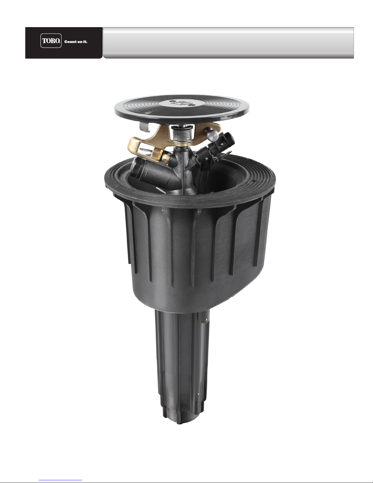
TS120 Pop-up Impact Sprinkler
Operating Manual
Page 2

Table of Contents
1. General 1
2. Safety 1
2.1. Use of symbols in these
operating instructions 1
2.2 Proper use 2
2.3 Clearly improper use 2
2.4 Safety information 2
2.5 Dangers of failing to observe
safety instructions 2
3. Description 3
3.1 Views TS120 Impact sprinkler
with VIH 3
3.2 Views TS120 Impact sprinkler
with VIH and TurfCup 4
3.3 Special tools 5
4. Technical data 6
5. Assembly, set-up and installation 6
5.1 Hazard warnings 6
8 Maintenance and repair work 15
8.1 Maintenance 15
8.2 Changing the nozzles 15
8.3 Changing the nozzles 15
8.4 Removing the Valve Insert 17
8.5 Removal / installation of the
control unit 18
9. Troubleshooting 20
9.1 Sprinkler malfunctions 20
5.2 Installation instructions 6
5.3 TS120 impact sprinkler
installation diagram 7
5.4 TS120 impact sprinkler
installation with VIH and TurfCup 8
5.5 Cabling 9
6. Commissioning and Operation 11
6.1 Potential danger 11
6.2 Commissioning 12
6.3 Setting the sector 13
7. Decommissioning and preparing
for winter 14
ii
Page 3

1. General
!
We presume that you are experienced in the eld of irrigation. We have therefore kept these instructions
brief and included only the information that it is imperative for you to have to use this product.
Any warranty claims can be accepted only if the sprinkler is used in accordance with these operating
instructions and if any defect emerges within the warranty period.
We reserve the right to make changes in line with technological advances, including without prior notice.
2. Safety
ese operating instructions contain some fundamental instructions that must be followed when
installing, operating, servicing and maintaining the sprinkler. It is therefore imperative that these
instructions are read by the tter and the relevant specialised sta / operators prior to installation and
commissioning.
Attention must be paid not just to the general safety information set out in this ‘Safety’ section, but also
to the special safety instructions included in the other sections.
2.1. Use of symbols in these operating instructions
Where failure to follow safety information can place individuals at risk, such information is specically
marked in these operating
instructions with the general danger symbol:
Warning of potential hand injuries
Warning of potential automatic start-up
In the case of safety information, where failure to follow it can damage the sprinkler and/or impair its
function, you will see the word:
WARNING!
1
Page 4
2.2 Proper use
!
e sprinkler is used for the even distribution of water onto lawns, green spaces and sports elds laid with
natural or articial grass. e water should be pre-cleaned and free of any coarse or brous contamination.
e water and ambient temperatures must be below the limits specied in the technical data.
2.3 Clearly improper use
• Operation of the pop-up sprinkler by unauthorised personnel (if the control unit is freely accessible).
• Operation of the sprinkler with the sector to be watered wrongly set, e.g. as the result of vandalism.
is can result in the jet of water being directed to the side away from the grassed area.
2.4 Safety information
Read the operating instructions, especially the safety information, before starting any work
on or with the sprinkler.
e specic safety instructions appear at the start of each section.
2.5 Dangers of failing to observe safety instructions
Failure to observe safety instructions can result both in people being placed at risk and in damage to the
environment and machine. Failure to observe safety instructions can lead to the loss of any rights to claim
compensation.
2
Page 5
3. Description
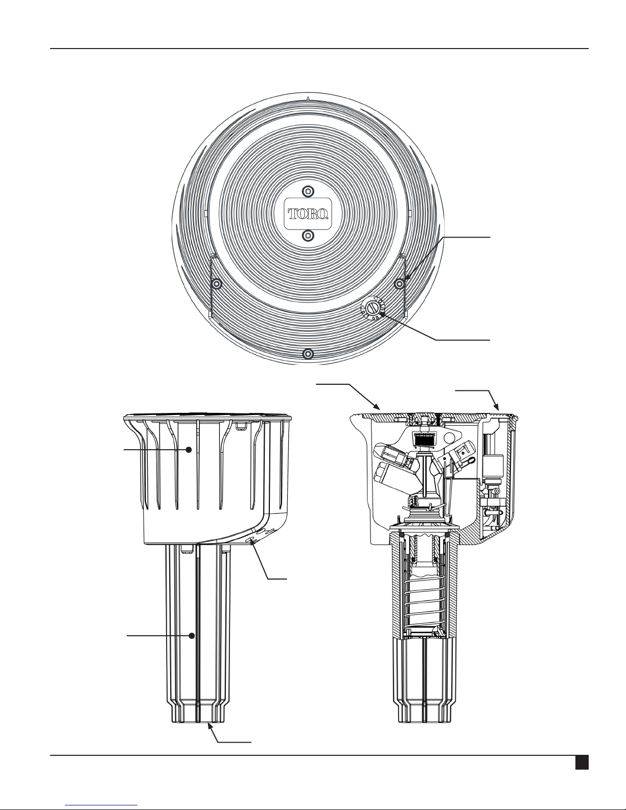
3.1 Views TS120 Impact Sprinkler
with VIH
Securing screw
Manual ON/OFF/Auto
control module
Housing
Guide Housing
Cover
Cable inlet
openings
Cover for cable
compartment
Main water
connection (1½”)
3
Page 6
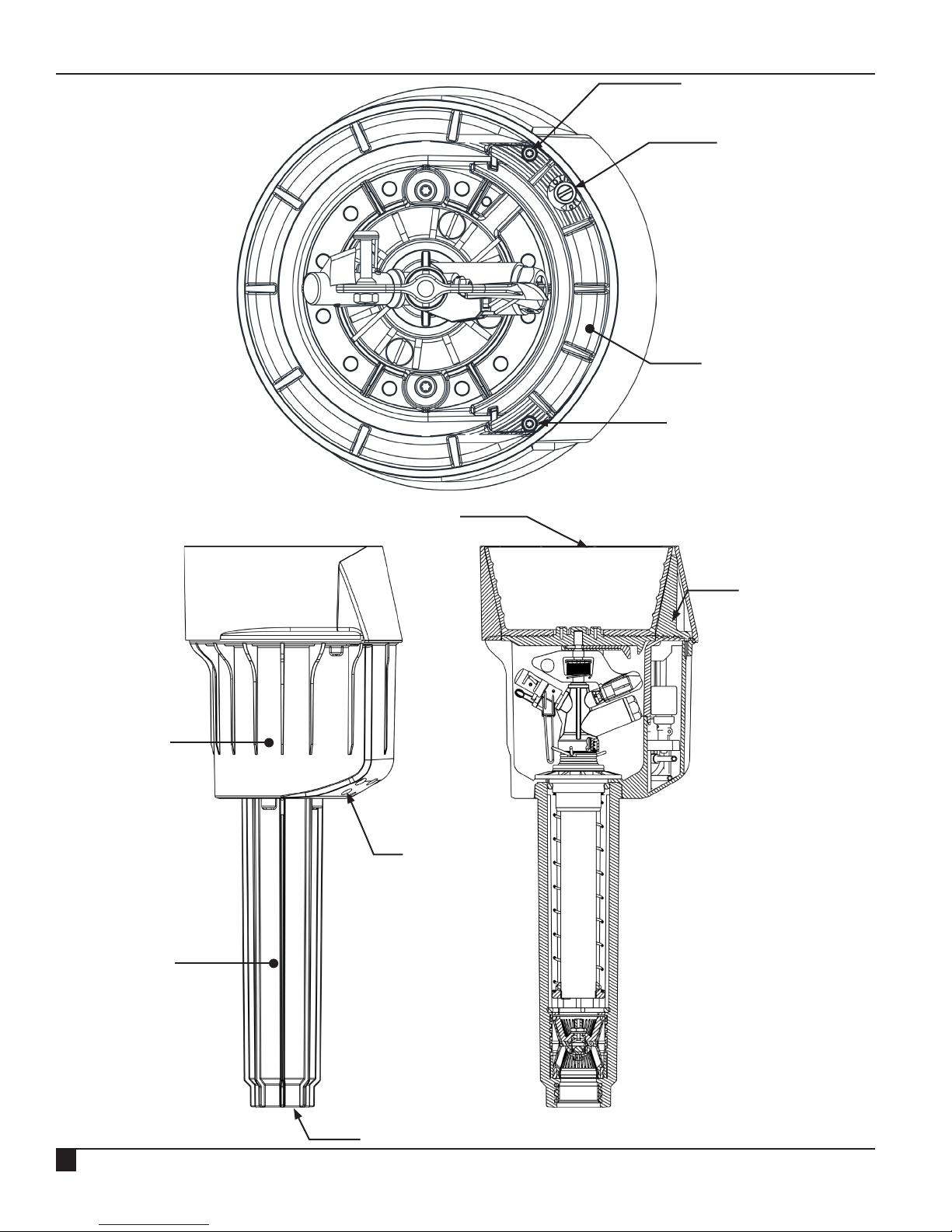
3.2 Views TS120 Impact Sprinkler
with VIH and TurfCup
Securing screw
Manual ON/OFF/Auto
control module
Cover for cable
compartment
Securing screw
Turf cup
Housing
Guide Housing
Cover for cable
compartment
Cable inlet
openings
4
Main water
connection (1½”)
Page 7
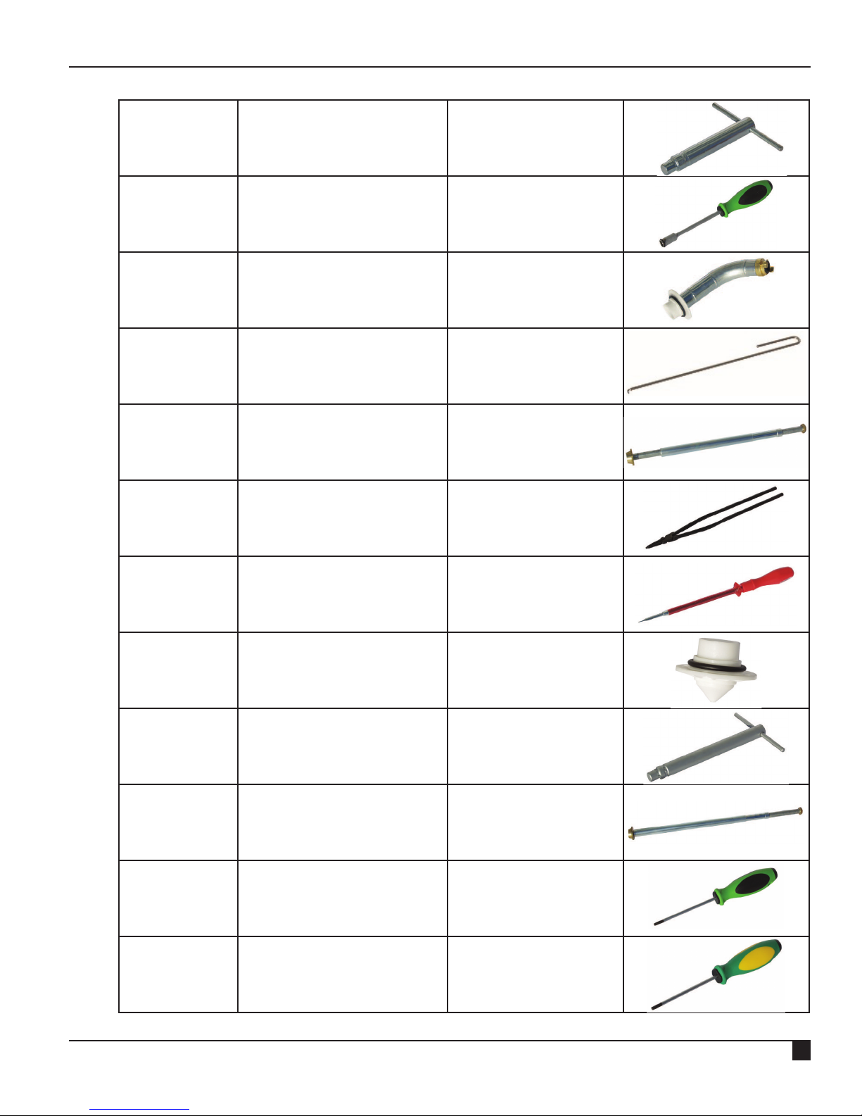
3.3 Special tools
RT19789 TS120 Assembly Key Disassembly of sprinkler
head and pipe axle
RT15745 TS120 SW 10 Socket Wrench
Changing driving nozzle
DIN 3125
RT17623 TS120 Flushing Equipment Flushing pipes
RT17839 Retaining Ring Removal
Removing retaining ring
Hook
RT17843 TS120 Valve Lifter Changing valve insert
RT17844 Retaining Ring Pliers Installation of retaining
ring
ZB98291 TS120 Expanding
Screw / unscrew ange
Screwdriver
RB17698 TS120 Flange for Guide
Housing
Plugging the guide
housing
RT83226 TS120 Assembly Key Disassembly of sprinkler
head and pipe axle
RT17845 TS120 Valve Lifter Changing valve insert
ZB98289 TORX-key T20 For screws at the com-
partment lid
ZB98297 TORX-key T25 For screws at the housing
– guide housing
5
Page 8
4. Technical data
!
!
Recommended operating pressure 72.5 to 116 psi
Permitted operating pressure 43.5 to 145 psi
WARNING!
Connection thread: G1½” NPT
Liquids: Water
Liquid temperature: 104° F max.
Ambient temperature: 140° F max.
For further data see separate data sheet.
The pressure at the sprinkler must not exceed 145 psi.
5. Assembly, set-up and installation
5.1 Hazard warnings
If any impurities get into the sprinkler, it is possible that the sprinkler could be destroyed
and that tters could be injured. Flush out the line thoroughly before connecting the water
supply.
Any unexpected emergence of a jet of water can lead to serious injury.
Make sure that the installation has been fully completed before turning on the water supply.
5.2 Installation instructions
• e thread connection on the pop-up sprinkler is 1½" NPT.
• For the thread seal, use hemp and sealing compound, e.g. Fermit Spezial or teon tape.
• e pop-up sprinkler should be tted in accordance with the 'Triton-L pop-up sprinkler installation
diagram' (see next page). In order to avoid any load pressure on the main line, you should denitely
use a exible connection.
• Providing a drainage pit directly connected to the drainage, as shown in the installation diagram, is
strongly recommended.
• For screwing in the connection joint the housing or housing edge of the pop-up sprinkler can be
rmly held or clamped.
6
Page 9

5.3 TS120 Impact sprinkler installation diagram
18”18” 2-8”2-8”
7
Page 10

5.4 TS120 impact sprinkler installation diagram
26”26” 2” - 8”2” - 8”
8
Page 11

5.5 Cabling
e laid 2-core cable is installed for the electrical connection of the TS120 impact sprinkler.
e cable is pulled through the right or left opening on the bottom of the housing into the
cable compartment.
Possible location
for pulling in the control cable
into the sprinkler
e DBR/Y-6 cable connector kit (article no.:
ZH90032) for connecting the control cable to the
coil tted inside the sprinkler.
Open the cover of the cable compartment and
connect the solenoid cable. Please use the DBR/Y-6
connector kit for the connection.
9
Page 12

Put back the cables into the cable compartment
and close the cover.
e electrical connection is thus not exposed to the
soil, but is instead protectively integrated inside the
sprinkler and accessible again at any time.
is simplies any search for faults and any
maintenance work can be carried out at any time
without any earthwork.
10
Page 13

6. Commissioning and Operation
!
!
!
6.1 Potential danger
When it starts up, the impact sprinkler rises up out of the housing and builds up full
pressure within about 5 seconds. The jet of water emitted can cause injury. For this reason
the following guidance must be followed when commissioning and operating the sprinkler:
• When the sprinkler is being operated in automatic mode,
there must be nobody present in the area.
• Operating personnel must not stand in the direction of the sprinkler’s jet.
Cover for cable
compartment
If the sprinkler is not installed ush with the ground, people may be injured by a fall as a
result of stumbling or tripping. Therefore check prior to commissioning and regularly during
ongoing use whether the sprinkler cover shuts ush with the surrounding ground.
The sprinkler must not be operated without a closed cover for the cable compartment.
During operation the sprinkler head props itself against the edge of the cover and cannot
rotate freely without the cover.
11
Page 14

6.2 Commissioning
!
a) Check electrical function:
Before any water supply to the sprinkler is opened, activate the coil by means of the controller. If you
hear a ‘clicking’ sound from the coil, the electrics are working properly. (e click is produced by the
movement of the armature.)
b) Ensure that <Manual opening> is set to AUTO (turn screw for <Manual opening> as far as it will go
to the left). is setting ensures that after water is supplied the sprinkler closes if it has no power.
c) Slowly open supply of water to the valve until operating pressure is built up.
It is possible that the sprinkler will briey open, but should then automatically close after at most
30 seconds.
d) Once the water supply has been opened and max. operating pressure has been reached,
check sprinkler and connection for leaks.
e) Check that sprinkler is working properly: Open sprinkler using <Manual opening> by moving the
screw for <Manual opening> into the position between AUTO and OFF (approx. 1 rotation).
Sprinkler head rises and starts to rotate.
Do not stand in front of the nozzle opening!
f) Close <Manual opening> and put into AUTO position (see point 6.2b).
Sprinkler must stop water ow within 30 seconds.
g) Keep repeating steps ‘e’ and ‘g’ until the sprinkler is working faultlessly.
h) Check once again that it works correctly when activated electrically from the controller.
12
Page 15

6.3 Setting the sector
With this impact sprinkler the sector setting is innitely variable.
You can adjust the area to be watered by pulling or pressing on the relevant end of the top
or bottom spring stop.
Setting the sector angle
WARNING!
Innitely variable setting is possible by pulling (not pressing) on the relevant end of
the top or bottom spring stop
Spring stop
Spring stop
Apply pressure here
13
Page 16

7. Decommissioning and preparing for winter
For decommissioning please turn o the water supply and electricity supply of the pump.
During times of possible frost please ensure that there is no standing water in the sprinkler.
e TS120 impact sprinkler has an automatic emptying system.
e sprinkler has a discharge valve and can thus be emptied by gravity. To do this, the water is let out at
the deepest point of the main pipe, as a result of which the sprinkler empties itself. (Deep point emptying)
e remaining water does not any causes in the event of freezing.
Electrically activate the solenoid several times so that any residual water
WARNING!
For springtime commissioning, see section 6.2.
is pushed out of the coil cavity.
During the winter we recommend activating the coil for approx. 1 minute
twice a week.
14
Page 17

8 Maintenance and repair work
!
An unexpected jet of water can cause serious injury. Prior to any maintenance or repair
work ensure that the water supply is securely turned off.
8.1 Maintenance
• Clean out the inside of the sprinkler housing using an industrial vacuum cleaner or similar
(as necessary).
• Cut sprinkler housing free of any overgrowing grass. It makes sense to carry out these jobs prior to
spring commissioning.
• Regularly check that the sprinkler is ush with the surface, especially in the case of natural grass.
8.2 Changing the nozzles
Please us the socket wrench for changing the nozzle.
Use SW10 for the driving nozzle and SW26 for the main nozzle.
8.3 Changing the nozzles
e sprinkler module needs to be taken out of the housing in order to carry out the repairs described
below.
• Lift the cover and secure the insert, with a
screw driver against snapping back. en clip
o the cover.
• Unscrew the 4 ange screws.
15
Page 18

• Pull sprinkler module out of the housing.
• Remove retaining ring in the housing bottom
using removal hook RT17839.
• Screw valve lifter in the housing base onto the
valve and pull upwards. A few gentle hits may
be necessary in order to take o the valve.
16
Page 19

8.4 Removing the Valve Insert
• Fitting the valve using valve lifter RT17843 (TC version RT17845).
• Prior to tting, check valve for any damage to the membrane.
• Check for any dirt and clear away.
• Screw the valve insert with the stainless steel disc onto the valve lifter.
e chamfered surface of the stainless steel disc must point to the valve insert.
• In order to make tting easier, the valve insert can be slightly lubricated with oil or grease.
Chamfer
• Insert the valve down into the guide housing by applying some gentle taps.
• Using pliers RT17844, now t the retaining ring into the groove provided for it above the thrust
washer.
WARNING!
The sprinkler insert is tted in reverse order.
17
Page 20

8.5 Removal / installation of the control unit
!
Ensure sprinkler is not under pressure.
Taking out the control unit
• Lift the cover and secure the insert with a screw driver against snapping back. en clip o the cover.
• Unscrew all 3 locking screws (2 screws at TC version) and take o cable compartment cover.
• Unclip control unit from protective casing and lift up.
• Twist out coil.
• When replacing the control unit, press back the clamp ring at the plug-in connector and
pull out the hose.
Control unit
18
Page 21

Fitting the control unit
• When buying a replacement part, the control unit is supplied with plug-and-socket connections. Push
hoses into plug-in grommets as far as they will go and ensure that the mounting ring springs back.
• Screw in coil.
• Clip control unit into protective casing.
• Secure housing cover using all three screws. (2 screws for TC version.)
• Check sprinkler is working properly as per point 6.2.
19
Page 22

9. Troubleshooting
9.1 Sprinkler malfunctions
Malfunction Cause Remedy
Sealing disc worn out Change sealing disc
Sprinkler not rotating or only
very slowly.
Sprinkler not rotating at all.
Sprinkler has poor jet Nozzle is blocked Unscrew nozzle, remove and clean.
Driving nozzle clogged Unscrew driving nozzle and clean
Minimum pressure of 43.5 psi not
Increase pressure
reached
Sector angle gets bigger during
operation.
Valve opens/closes only with
manual opening, but not on any
electric signal
Valve fails to open even with
manual opening
Valve fails to close
Spring stop is loose.
Fit new spring stop.
Spring force has slackened.
Spring stop has been
overextended.
Screw for <Manual opening> is set
to OFF
Turn screw to the left as far as it will
go, to Auto.
Core is jammed in the coil Remove coil and clean core
No / inadequate power supply Establish 24V AC power supply
Defective coil Check coil resistance (should be ap-
prox. 35 ohms). Replace if necessary.
Relief channel for coil blocked Clean channel
Control pipe to the solenoid
Replace control pipe
clogged or bent
Control water hole or relief hole
Clean control water / relief hole
blocked
Supply line under no / insucient
Establish pressure supply
pressure
Coil seat dirty Clean coil seat
Bits of dirt between valve seat and
Clean valve seat and sealing plate
sealing plate
Output pressure at sprinkler
nozzle too low or casting range
too short
We reserve the right to make changes in line with technological advances, including without prior notication.
20
Defective membrane Remove valve and replace membrane
Control water lter dirty or
Clean control water lter
Control water lter of the valve
lter dirty
Control pipe defect Change control pipe
Stones and bits of dirt are hinder-
Clean valve and ush sprinkler
ing an unimpeded passage of water
Valve insert is blocked Clean valve insert see point 8.3
Page 23

Notes
21
Page 24

© 2017 e Toro Company • Irrigation Division • www.toro.com Part Number 373-0947 Rev. A
22
 Loading...