

Page 1
FormNo.3390-434RevA
TRX-16,TRX-20,andTRX-26
Trencher
ModelNo.22972—SerialNo.315000001andUp
ModelNo.22972G—SerialNo.315000001andUp
ModelNo.22973—SerialNo.315000001andUp
ModelNo.22973G—SerialNo.315000001andUp
ModelNo.22974—SerialNo.315000001andUp
Registeratwww.T oro.com.
OriginalInstructions(EN)
*3390-434*A
Page 2

Thismachineisdesignedtodigtrenchesinsoiltobury
G007797
1
cablingandpipingforvariousapplications.Itisnotintended
tocutrock,wood,oranyothermaterialotherthansoil.
WARNING
CALIFORNIA
Proposition65Warning
Thisproductcontainsachemicalorchemicals
knowntotheStateofCaliforniatocausecancer,
birthdefects,orreproductiveharm.
Theengineexhaustfromthisproduct
containschemicalsknowntotheStateof
Californiatocausecancer,birthdefects,
orotherreproductiveharm.
DANGER
Theremaybeburiedpower,gas,and/ortelephone
linesintheworkarea.Shockorexplosionmay
occurifyoudigintothem.
Havethepropertyorworkareamarkedforburied
linesanddonotdiginmarkedareas.Contactyour
localmarkingserviceorutilitycompanytohavethe
propertymarked(forexample,intheUnitedStates,
call811forthenationwidemarkingservice).
ThissparkignitionsystemcomplieswithCanadianICES-002.
Important:Thisengineisnotequippedwithaspark
arrestermufer.ItisaviolationofCaliforniaPublic
ResourceCodeSection4442touseoroperatetheengine
onanyforest-covered,brush-covered,orgrass-covered
land.Otherstatesorfederalareasmayhavesimilarlaws.
Theenclosed
informationregardingtheUSEnvironmentalProtection
Agency(EPA)andtheCaliforniaEmissionControl
Regulationofemissionsystems,maintenance,and
warranty.Replacementsmaybeorderedthroughthe
enginemanufacturer.
EngineOwner'sManual
issuppliedfor
Introduction
Readthisinformationcarefullytolearnhowtooperateand
maintainyourproductproperlyandtoavoidinjuryand
productdamage.Youareresponsibleforoperatingthe
productproperlyandsafely.
YoumaycontactTorodirectlyatwww .Toro.comforproduct
andaccessoryinformation,helpndingadealer,ortoregister
yourproduct.
Wheneveryouneedservice,genuineToroparts,oradditional
information,contactanAuthorizedServiceDealerorToro
CustomerServiceandhavethemodelandserialnumbersof
yourproductready .Figure1illustratesthelocationofthe
modelandserialnumbersontheproduct.Writethenumbers
inthespaceprovided.
Figure1
1.Modelandserialnumberplate
ModelNo.
SerialNo.
Thismanualidentiespotentialhazardsandhassafety
messagesidentiedbythesafetyalertsymbol(Figure2),
whichsignalsahazardthatmaycauseseriousinjuryordeath
ifyoudonotfollowtherecommendedprecautions.
ThisproductcomplieswithallrelevantEuropeandirectives;
fordetails,pleaseseetheseparateproductspecicDeclaration
ofConformity(DOC)sheet.
Figure2
1.Safetyalertsymbol
Thismanualuses2wordstohighlightinformation.
Importantcallsattentiontospecialmechanicalinformation
©2015—TheToro®Company
8111LyndaleAvenueSouth
Bloomington,MN55420
andNoteemphasizesgeneralinformationworthyofspecial
attention.
Contactusatwww.Toro.com.
2
PrintedintheUSA
AllRightsReserved
Page 3

Contents
Safety...........................................................................4
SafeOperatingPractices...........................................4
SoundPressure.......................................................6
SoundPower..........................................................6
Vibration................................................................6
SlopeIndicator.......................................................7
SafetyandInstructionalDecals.................................8
Setup...........................................................................12
1InstallingtheBoomandChain...............................12
2CheckingFluidLevels...........................................13
3ChargingtheBattery(ElectricStartModels
Only)................................................................13
ProductOverview.........................................................13
Controls...............................................................13
Specications........................................................16
Attachments/Accessories........................................16
Operation....................................................................16
RecommendedFuel................................................16
CheckingtheEngine-OilLevel.................................17
CheckingtheHydraulicFluidLevel...........................17
StartingandStoppingtheEngine..............................19
StoppingtheMachine.............................................19
MovingaNon-functioningMachine.........................19
DiggingaTrench....................................................20
SecuringtheMachineforTransport..........................20
LiftingtheMachine................................................20
OperatingTips......................................................21
Maintenance.................................................................22
RecommendedMaintenanceSchedule(s)......................22
PremaintenanceProcedures........................................23
RemovingtheCoverPlate........................................23
InstallingtheCoverPlate.........................................23
RemovingtheBottomShield...................................23
InstallingtheBottomShield.....................................23
Lubrication...............................................................24
GreasingtheMachine.............................................24
GreasingtheTrencherHousing................................24
EngineMaintenance..................................................25
ServicingtheAirCleaner(Models22972and
22973)...............................................................25
ServicingtheAirCleaner(Model22974)....................26
ServicingtheEngineOil..........................................27
ServicingtheSparkPlug..........................................28
FuelSystemMaintenance...........................................29
DrainingtheFuelTank...........................................29
ReplacingtheFuelFilter..........................................30
ElectricalSystemMaintenance....................................30
ServicingtheBattery(Models22973and
22974)...............................................................30
ReplacingtheFuses(Models22973and
22974)...............................................................32
DriveSystemMaintenance.........................................33
ServicingtheTracks................................................33
BeltMaintenance......................................................35
ReplacingthePumpDriveBelt.................................35
ControlsSystemMaintenance.....................................36
AdjustingtheTractionControlAlignment.................36
AdjustingtheTractionControlNeutral
Position.............................................................37
AdjustingtheTrackingoftheTractionControl,
FullForwardPosition..........................................37
HydraulicSystemMaintenance....................................38
ReplacingtheHydraulicFilter..................................38
ChangingtheHydraulicFluid...................................38
CheckingtheHydraulicLines...................................39
TrencherMaintenance................................................40
ReplacingtheDiggingTeeth....................................40
CheckingandAdjustingtheDiggingChainand
Boom................................................................40
ReplacingtheDriveSprocket...................................40
Cleaning...................................................................42
RemovingDebrisfromtheMachine..........................42
Storage........................................................................42
Troubleshooting...........................................................44
Schematics...................................................................46
3
Page 4

Safety
Improperuseormaintenancebytheoperatororowner
canresultininjury.Toreducethepotentialforinjury,
complywiththesesafetyinstructionsandalways
payattentiontothesafetyalertsymbol
means:
instruction.Failuretocomplywiththeinstructionmay
resultinpersonalinjuryordeath.
Caution
,
Warning
,or
Danger
SafeOperatingPractices
Thisproductiscapableofamputatinghandsandfeet.Always
followallsafetyinstructionstoavoidseriousinjuryordeath.
WARNING
Engineexhaustcontainscarbonmonoxide,an
odorless,deadlypoisonthatcankillyou.
Donotruntheengineindoorsorinanenclosed
area.
Training
•ReadtheOperator'sManualandothertrainingmaterial.If
theoperator(s)ormechanic(s)can’treadEnglish,itisthe
owner'sresponsibilitytoexplainthismaterialtothem.
•Becomefamiliarwiththesafeoperationoftheequipment,
operatorcontrols,andsafetysigns.
•Alloperatorsandmechanicsshouldbetrained.The
ownerisresponsiblefortrainingtheusers.
•Neverletchildrenoruntrainedpeopleoperateorservice
theequipment.Localregulationsmayrestricttheageof
theoperator.
•Theowner/usercanpreventandisresponsiblefor
accidentsorinjuriesoccurringtohimselforherself,other
peopleorproperty.
Preparation
•Evaluatetheterraintodeterminewhataccessoriesand
attachmentsareneededtoproperlyandsafelyperform
thejob.Onlyuseaccessoriesandattachmentsapproved
bythemanufacturer.
•Wearappropriateclothingincludinghardhat,safety
glasses,longpants,safetyshoes,andhearingprotection.
Longhair,looseclothingorjewelrymaygettangledin
movingparts.
•Inspecttheareawheretheequipmentistobeusedand
removeallobjectssuchasrocks,toys,andwirewhichcan
bethrownbythemachine.
•Useextracarewhenhandlinggasolineandotherfuels.
Theyareammableandvaporsareexplosive.
–Useonlyanapprovedcontainer
–Neverremovethegascaporaddfuelwiththeengine
running.Allowtheenginetocoolbeforerefueling.
Donotsmoke.
,which
—personalsafety
–Neverrefuelordrainthemachineindoors.
•Checkthattheoperatorpresencecontrols,safetyswitches,
andshieldsareattachedandfunctioningproperly .Donot
operateunlesstheyarefunctioningproperly .
Operation
•Neverrunanengineinanenclosedarea.
•Onlyoperateingoodlight,keepingawayfromholesand
hiddenhazards.
•Besurealldrivesareinneutralandtheparkingbrakeis
engagedbeforestartingtheengine.Onlystarttheengine
fromtheoperator'sposition.
•Slowdownanduseextracareonhillsides.Besureto
travelintherecommendeddirectiononhillsides.Turf
conditionscanaffectthemachine'sstability.
•Slowdownandusecautionwhenmakingturnsandwhen
changingdirectionsonslopes.
•Neveroperatewithouttheguardssecurelyinplace.Be
sureallinterlocksareattached,adjusted,andfunctioning
properly.
•Donotchangetheenginegovernorsettingoroverspeed
theengine.
•Stoponlevelground,lowertheboom,disengagethe
trencherhydraulics,engagetheparkingbrake,andshut
offtheenginebeforeleavingtheoperator'spositionfor
anyreason.
•Keephandsandfeetawayfromthemovingchain,digging
teeth,andspoilsauger.
•Lookbehindanddownbeforebackinguptobesureof
aclearpath.
•Nevercarrypassengersandkeeppetsandbystanders
away.
•Slowdownandusecautionwhenmakingturnsand
crossingroadsandsidewalks.
•Donotoperatethemachineundertheinuenceof
alcoholordrugs.
•Usecarewhenloadingorunloadingthemachineintoa
trailerortruck.
•Usecarewhenapproachingblindcorners,shrubs,trees,
orotherobjectsthatmayobscurevision.
•Ensurethattheareaisclearofotherpeoplebefore
operatingthemachine.Stopthemachineifanyoneenters
thearea.
•Neverleavearunningmachineunattended.Alwayslower
theboom,stoptheengine,settheparkingbrake,and
removethekeybeforeleaving.
•Neverjerkthecontrols;useasteadymotion.
•Watchfortrafcwhenoperatingnearorcrossing
roadways.
•Donottouchpartswhichmaybehotfromoperation.
Allowthemtocoolbeforeattemptingtomaintain,adjust,
orservice.
4
Page 5

•Ensurethatyouoperatethemachineinareaswhere
therearenoobstaclesincloseproximitytotheoperator.
Failuretomaintainadequatedistancefromtrees,walls,
andotherbarriersmayresultininjuryasthemachine
backsupduringoperationiftheoperatorisnotattentive
tothesurroundings.Onlyoperatetheunitinareaswhere
thereissufcientclearancefortheoperatortosafely
maneuvertheproduct.
•Beforedigging,havetheareamarkedforunderground
utilities,anddonotdiginmarkedareas.
•Locatethepinchpointareasmarkedonthemachineand
keephandsandfeetawayfromtheseareas.
•Lightningcancausesevereinjuryordeath.Iflightning
isseenorthunderisheardinthearea,donotoperate
themachine;seekshelter.
MaintenanceandStorage
•Disengagethetrencherhydraulics,lowertheboom,set
theparkingbrake,stoptheengine,andremovethekey.
Waitforallmovementtostopbeforeadjusting,cleaning,
orrepairing.
•Cleandebrisfromthechain,diggingteeth,boom,
trencherhead,drives,mufers,andenginetohelpprevent
res.Cleanupoilorfuelspillage.
•Lettheenginecoolbeforestoringanddonotstorenear
ame.
•Donotstorefuelnearamesordrainindoors.
•Parkthemachineonlevelground.Neverallowuntrained
personneltoservicethemachine.
•Usejackstandstosupportcomponentswhenrequired.
SlopeOperation
Slopesareamajorfactorrelatedtoloss-of-controland
tip-overaccidents,whichcanresultinsevereinjuryordeath.
Allslopesrequireextracaution.
•Donotoperatethemachineonhillsidesorslopes
exceedingtheanglesrecommendedinthefollowingtable.
ModelFrontFacing
22972
22973
22974
Note:SeealsotheSlopeIndicator(page7).
Uphill
15°14°19°
13°14°19°
11°11°16°
•Operateupanddownslopeswiththefrontendof
themachineuphill.
•Removeobstaclessuchasrocks,treelimbs,etc.fromthe
workarea.Watchforholes,ruts,orbumps,asuneven
terraincouldoverturnthemachine.Tallgrasscanhide
obstacles.
•UseonlyToro-approvedaccessories.Accessoriescan
changethestabilityandtheoperatingcharacteristics
ofthemachine.Warrantymaybevoidedifusedwith
unapprovedaccessories.
•Keepallmovementsonslopesslowandgradual.Donot
makesuddenchangesinspeedordirection.
•Avoidstartingorstoppingonaslope.Ifthemachine
losestraction,proceedslowly,straightdowntheslope.
•Avoidturningonslopes.Ifyoumustturn,turnslowly
andkeeptheheavyendofthemachineuphill.
•Donotoperateneardrop-offs,ditches,orembankments.
Themachinecouldsuddenlyturnoverifatrackgoes
overtheedgeofaclifforditch,orifanedgecavesin.
•Donotoperateonwetgrass.Reducedtractioncould
causesliding.
•Donotparkthemachineonahillsideorslopewithout
loweringtheboomtotheground,settingtheparking
brake,andchockingthetracks.
RearFacing
Uphill
SideFacing
Uphill
•Carefullyreleasepressurefromcomponentswithstored
energy.
•Disconnectthebattery(electricstartmodelsonly)or
removethesparkplugwiresbeforemakinganyrepairs.
Disconnectthenegativeterminalrstandthepositive
last.Reconnectpositiverstandnegativelast.
•Keephandsandfeetawayfrommovingparts.Ifpossible,
donotmakeadjustmentswiththeenginerunning.
•Keepallpartsingoodworkingconditionandallhardware
tightened.Replaceallwornordamageddecals.
•Keepnutsandboltstight.Keepequipmentingood
condition.
•Nevertamperwithsafetydevices.
•Keepthemachinefreeofgrass,leaves,orotherdebris
build-up.Cleanupoilorfuelspillage.Allowthemachine
tocoolbeforestoring.
•Useextracarewhenhandlinggasolineandotherfuels.
Theyareammableandvaporsareexplosive.
–Useonlyanapprovedcontainer.
–Neverremovethegascaporaddfuelwhenthe
engineisrunning.Allowtheenginetocoolbefore
refueling.Donotsmoke.
–Neverrefuelthemachineindoors.
–Neverstorethemachineorfuelcontainerinside
wherethereisanopename,suchasnearawater
heaterorfurnace.
–Neverllacontainerwhileitisinsideavehicle,trunk,
pick-upbed,oranysurfaceotherthantheground.
–Keepcontainernozzleincontactwiththetankduring
lling.
•Stopandinspecttheequipmentifyoustrikeanobject.
Makeanynecessaryrepairsbeforerestarting.
•UseonlygenuineT ororeplacementpartstoensurethat
originalstandardsaremaintained.
•Batterysafety(electricstartmodelsonly):
5
Page 6

–Chargebatteriesinanopen,wellventilatedarea,away
fromsparkandames.Unplugthechargerbefore
connectingordisconnectingitfromthebattery.Wear
protectiveclothinganduseinsulatedtools.
–Batteryacidispoisonousandcancauseburns.Avoid
contactwithskin,eyes,andclothing.Protectyour
face,eyes,andclothingwhenworkingwithabattery.
Soundpowerlevelwasdeterminedaccordingtothe
proceduresoutlinedinENISO3744.
Model22974
Thisunithasaguaranteedsoundpowerlevelof107dBA,
whichincludesanUncertaintyValue(K)of3.75dBA.
–Batterygasescanexplode.Keepcigarettes,sparks
andamesawayfromthebattery.
•Keepyourbodyandhandsawayfrompinholeleaks
ornozzlesthatejecthighpressurehydraulicuid.Use
cardboardorpapertondhydraulicleaks;neveruse
yourhands.Hydraulicuidescapingunderpressurecan
penetrateskinandcauseinjuryrequiringsurgerywithina
fewhoursbyaqualiedsurgeonorgangrenemayresult.
SoundPressure
Model22972
Thisunithasasoundpressurelevelattheoperator’searof89
dBA,whichincludesanUncertaintyValue(K)of1.0dBA.
Soundpressurelevelwasdeterminedaccordingtothe
proceduresoutlinedinENISO11201.
Model22973
Thisunithasasoundpressurelevelattheoperator’searof90
dBA,whichincludesanUncertaintyValue(K)of1.0dBA.
Soundpressurelevelwasdeterminedaccordingtothe
proceduresoutlinedinENISO11201.
Soundpowerlevelwasdeterminedaccordingtothe
proceduresoutlinedinENISO3744.
Vibration
Model22972
Measuredvibrationlevelforrighthand=2.1m/s
Measuredvibrationlevelforlefthand=2.0m/s
UncertaintyValue(K)=1.1m/s
Measuredvaluesweredeterminedaccordingtotheprocedures
outlinedinENISO20643.
Model22973
Measuredvibrationlevelforrighthand=2.3m/s
Measuredvibrationlevelforlefthand=2.1m/s
UncertaintyValue(K)=1.1m/s
Measuredvaluesweredeterminedaccordingtotheprocedures
outlinedinENISO20643.
Model22974
2
2
2
2
2
2
Model22974
Thisunithasasoundpressurelevelattheoperator’searof93
dBA,whichincludesanUncertaintyValue(K)of1.0dBA.
Soundpressurelevelwasdeterminedaccordingtothe
proceduresoutlinedinENISO11201.
SoundPower
Model22972
Thisunithasaguaranteedsoundpowerlevelof107dBA,
whichincludesanUncertaintyValue(K)of3.75dBA.
Soundpowerlevelwasdeterminedaccordingtothe
proceduresoutlinedinENISO3744.
Model22973
Thisunithasaguaranteedsoundpowerlevelof108dBA,
whichincludesanUncertaintyValue(K)of3.75dBA.
Measuredvibrationlevelforrighthand=1.8m/s
Measuredvibrationlevelforlefthand=2.0m/s
UncertaintyValue(K)=1.00m/s
Measuredvaluesweredeterminedaccordingtotheprocedures
outlinedinENISO20643.
2
2
2
6
Page 7
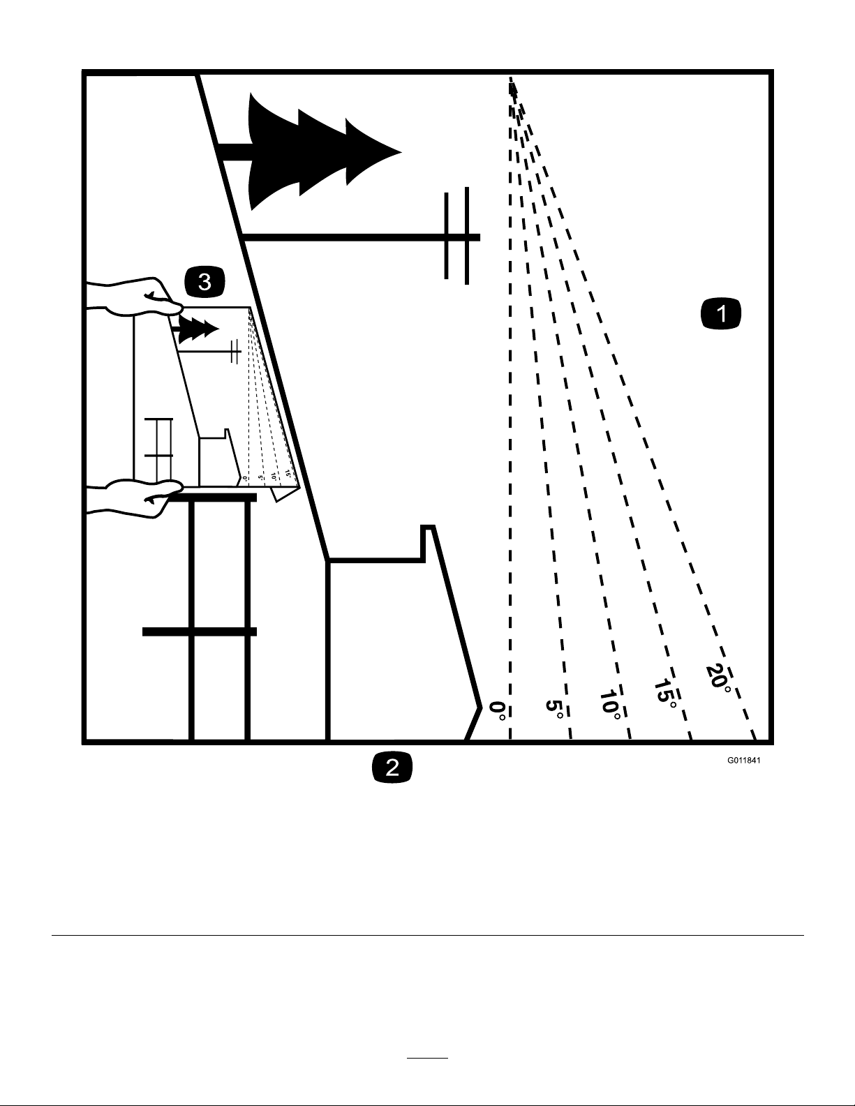
SlopeIndicator
G011841
Figure3
Thispagemaybecopiedforpersonaluse.
1.Todeterminethemaximumslopeyoucansafelyoperatethemachineon,refertotheSlopeOperationsection.Usetheslope
indicatortodeterminethedegreeofslopeofhillsbeforeoperating.Donotoperatethismachineonaslopegreaterthanthat
speciedintheSlopeOperationsection.Foldalongtheappropriatelinetomatchtherecommendedslope.
2.Alignthisedgewithaverticalsurface,atree,building,fencepole,etc.
3.Exampleofhowtocompareslopewithfoldededge.
7
Page 8
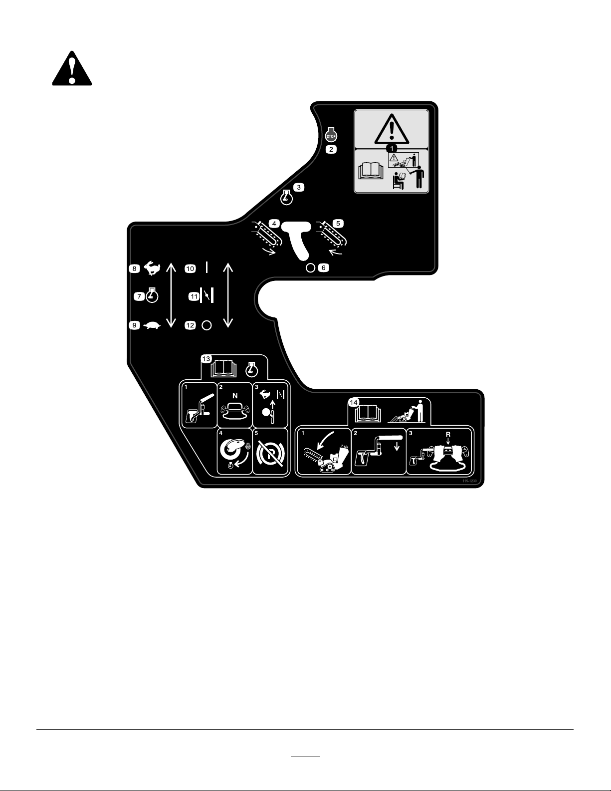
SafetyandInstructionalDecals
Safetydecalsandinstructionsareeasilyvisibletotheoperatorandarelocatednearanyareaofpotential
danger.Replaceanydecalthatisdamagedorlost.
115-1230
1.Warning—donotoperatethismachineunlessyouaretrained.
2.Engine—stop
3.Engine—run
4.Trencherchain—reverse
5.Trencherchain—forward
6.Trencherchain—off
7.Enginethrottle
8.Fast
9.Slow
10.Choke
11.On/Closed
12.Off/Open
13.ReadtheOperator'sManualbeforestartingtheengine;tostarttheengine,movethetrenchercontrolleverintotheOffposition,
placethetractioncontrolinNeutral,movetheenginespeedtoFastandthechoketoOn/Closed,turntheignitionkeytorun,
andreleasetheparkingbrakeoncetheenginehasstarted.
14.ReadtheOperator'sManualbeforeoperatingthetrencher;tooperatethetrencher,lowertheboom,movethetrenchercontrol
levertothereferencebar,pullthetractioncontrolrearwardtomoveinreverseanddigthetrench.
8
Page 9
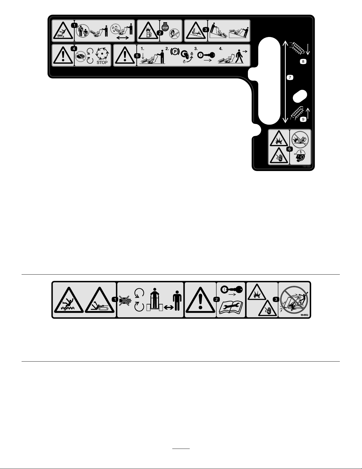
115-1231
1.Cutting/dismembermenthazardofbystanders,
trencher—keepbystandersasafedistancefromthemachine;
donotoperatethetrencherchainwhiletransportingthe
machine.
2.Explosionhazard,fueling—stoptheengineandextinguish
allameswhenfueling.
3.Tipping/crushinghazard—lowerthetrencherheadwhen
operatingonslopes.
4.Warning—stayawayfrommovingparts;waitforallmoving
partstostop
5.Warning—lowertheboom,engagetheparkingbrakeand
stoptheengine,removetheignitionkey,beforeleavingthe
machine.
6.Explosionhazard;shockhazard—donotusemachinenear
buriedutilitylines;contacttheproperagenciesbeforedigging.
7.Boomelevation
8.Lowertheboom
9.Raisetheboom
99-9952
1.Cuttinghazard,chainandauger—stayawayfrommovingpartsandkeepbystandersawayfromthemachine.
2.Warning—stoptheengineandremovethekeybeforepreformingandmaintenanceorrepairs.
3.Explosionand/orelectricshockhazard—donotdiginareaswithburiedgasorpowerlines.
9
Page 10
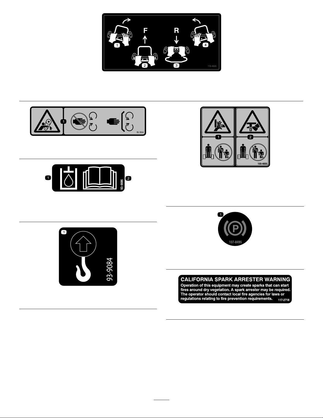
115-4020
1.Turnright3.Reverse
2.Forward
93-7814
1.Entanglementhazard,belt—stayawayfrommovingparts.
93-6686
1.Hydraulicoil
2.ReadtheOperator'sManual.
4.Turnleft
100-4650
1.Crushinghazardofhand—keepbystandersasafedistance
fromthemachine.
2.Crushinghazardoffoot—keepbystandersasafedistance
fromthemachine.
1.Liftpoint
107-8495
1.Parkingbrake
93-9084
2.Tie-downpoint
117–2718
10
Page 11

BatterySymbols
Someorallofthesesymbolsareonyourbattery
1.Explosionhazard
2.Nore,opename,or
smoking.
3.Causticliquid/chemical
burnhazard
4.Weareyeprotection9.Flusheyesimmediately
5.ReadtheOperator's
Manual.
6.Keepbystandersasafe
7.Weareyeprotection;
8.Batteryacidcancause
10.Containslead;donot
distancefromthebattery.
explosivegasescan
causeblindnessandother
injuries
blindnessorsevereburns.
withwaterandgetmedical
helpfast.
discard.
11
Page 12
Setup
LooseParts
Usethechartbelowtoverifythatallpartshavebeenshipped.
ProcedureDescription
Boom(soldseparately)
1
2
3
Chain(soldseparately)
Nopartsrequired
Nopartsrequired
1
InstallingtheBoomandChain
Partsneededforthisprocedure:
1
Boom(soldseparately)
1
Chain(soldseparately)
Procedure
Important:Thereareseveralboomandchainsize
congurationsavailable.RefertoyouAuthorizedService
Dealertoobtaintheappropriateboomandchainto
meetyourrequirements.
1.Stoptheengineandremovethekey.
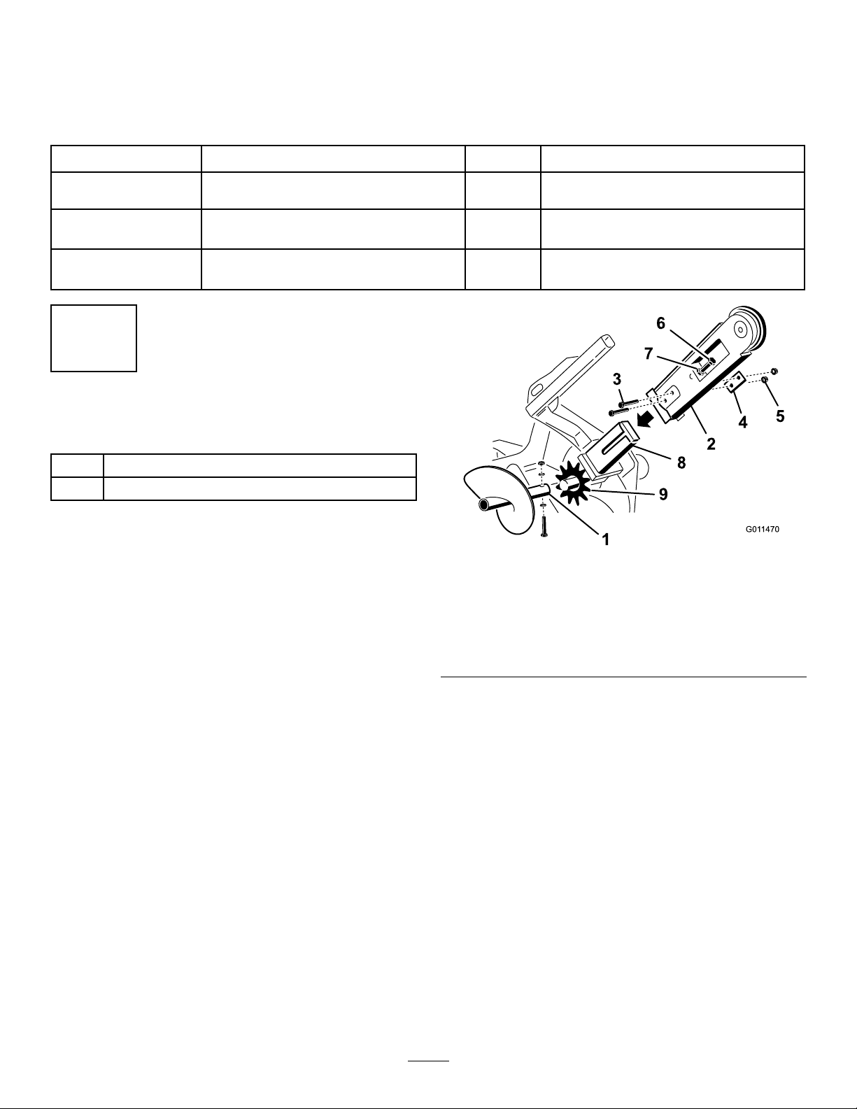
2.Removethebolt,2saddlewashers,andnutsecuring
thespoilsaugerandremovetheauger(Figure4).
Note:Savethefastenersforfutureuse.
Qty.
1
1
–
–
1.Spoilsauger
2.Boom7.Jamnut
3.Bolts8.Armonthedrivehead
4.Doublewasher9.Drivesprocket
5.Nuts
3.Removethe2bolts,nuts,anddoublewashersfromthe
sidesoftheboom(Figure4).
Installtheboomandchain.
Checktheuidlevels.
Chargethebattery.
Figure4
Use
6.Adjustingbolt
4.Loosentheadjustingboltandjamnut(Figure4).
5.Slidetheboomoverthearmonthedrivehead.
6.Installthe2bolts,nuts,anddoublewashersremovedin
step3throughtheboomandarm,butdonottighten
them.
7.Ifthechainisnotconnected,connectthelinksby
pressingorhammeringtheclevispinsuppliedwiththe
chainthroughthelinks.
Important:T oavoidbendingthechainlinks,
placeblocksunderandbetweenthelinkswhen
hammeringtheclevispinthrough.
8.Securetheclevispinwiththecotterpinsuppliedwith
thechain.
12
Page 13
9.Loopthediggingchainovertheaugerdriveshaftand
G007801
5
6
783
4
1
2
ontothedrivesprocket,ensuringthatthediggingteeth
pointforwardontheupperspan.
10.Settheupperspanofthechainintoplaceonthe
trencherboom,thenwrapthechainaroundtheroller
attheendoftheboom.
11.Threadtheadjustmentboltintotheboomandturnit
inuntilthereis3.8to6.3cm(1-1/2to2-1/2inches)of
slackinthechainonthebottomspan.
12.Threadthejamnutdowntheadjustingboltandtighten
itsecurelyagainsttheboom.
13.Torquethe2boltsandnutssecuringtheboomto183
to223N-m(135to165ft-lb).
14.Installthespoilsaugerusingthebolt,2saddlewasher,
andnutyouremovedpreviously.
15.Torquetheboltandnutto101N-m(75ft-lb).
2
ProductOverview
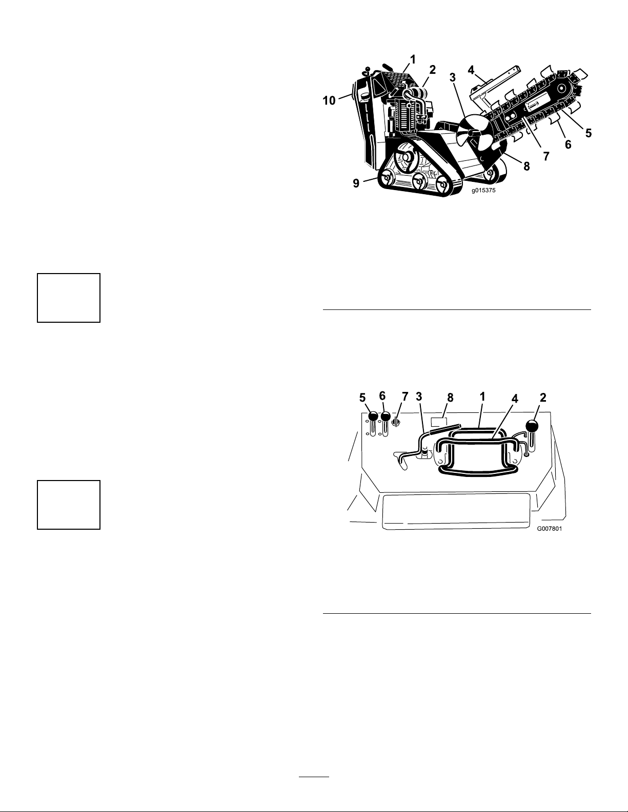
Figure5
1.Control
panel
2.Engine
3.Spoils
auger
4.Chain
guard
5.Chain
6.Digging
teeth
7.Boom10.Reverse
safety
plate
8.Trencher
head
9.Track
CheckingFluidLevels
NoPartsRequired
Procedure
Beforestartingtheengineforthersttime,checktheengine
oilandhydraulicuidlevels;refertoCheckingtheEngine-Oil
Level(page17)andCheckingtheHydraulicFluidLevel(page
17)formoreinformation.
3
ChargingtheBattery(Electric StartModelsOnly)
NoPartsRequired
Procedure
Chargethebattery;refertoChargingtheBattery(page32)
formoreinformation.
Controls
Becomefamiliarwithallthecontrols(Figure6)beforeyou
starttheengineandoperatethemachine.
Figure6
1.Tractioncontrol5.Throttlelever
2.Boomelevationlever
3.Trenchercontrollever7.Keyswitch
4.Referencebar
KeySwitch,Model22972
Thekeyswitchhas2positions:OffandRun.
Tostarttheengine,rotatethekeytotheRunposition,then
pulltherecoilhandleontheengine.
6.Chokelever
8.Hourmeter
Tostoptheengine,rotatethekeytotheOffposition.
13
Page 14

KeySwitch,ElectricStartModels
G008131
G008132
Thekeyswitchhasthreepositions:Off,Run,andStart.
Tostarttheengine,rotatethekeytotheStartposition.
Releasethekeywhenenginestartsanditwillmove
automaticallytotheRunposition.
Tostoptheengine,rotatethekeytotheOffposition.
ThrottleLever
Movethecontrolforwardtoincreasetheenginespeedand
rearwardtodecreasespeed.
ChokeLever
Beforestartingacoldengine,movethechokeleverforward.
Aftertheenginestarts,regulatethechoketokeeptheengine
runningsmoothly.Assoonaspossible,movethechokelever
allthewayrearward.
Note:Awarmenginerequireslittleornochoking.
HourMeter
Whentheengineisoff,thehourmeterdisplaysthenumber
ofhoursofoperationthathavebeenloggedonthemachine.
ReferenceBar
Whendrivingthemachine,usethereferencebarasahandle
andaleveragepointforcontrollingthetractioncontroland
thetrenchercontrollever.Toensuresmooth,controlled
operation,donottakebothhandsoffofthereferencebar
whileoperatingthemachine.
Figure8
•Tomoverearward,movethetractioncontrolrearward
(Figure9).Whenreversing,lookbehindfor
obstructionsandkeepyourhandsonthereference
bar(Figure7).
Figure9
•Toturnright,rotatethetractioncontrolclockwise(Figure
10).
TractionControl
Figure7
1.Referencebar(doesnotmovetogiveyouareferencepoint
andaxedhandletoholdwhileoperatingthetractionunit)
2.Tractioncontrol(movestocontrolthemachine)
•Tomoveforward,movethetractioncontrolforward
(Figure8).
Figure10
•Toturnleft,rotatethetractioncontrolcounterclockwise
(Figure11).
Figure11
•Tostop,releasethetractioncontrol(Figure7).
Note:Thefartheryoumovethetractioncontrolinany
direction,thefasterthemachinewillmoveinthatdirection.
14
Page 15
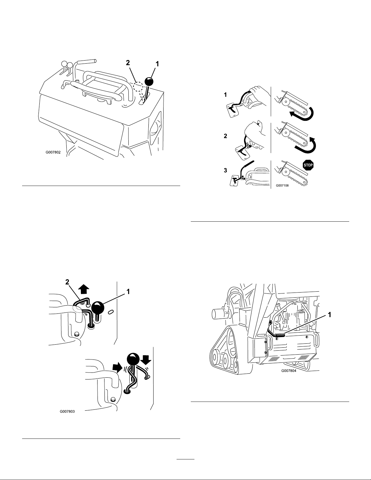
BoomElevationLever
G007804
1
TrencherControlLever
Tolowertheboom,slowlymovetheleverforward(Figure
12).
Toraisetheboom,slowlymovetheleverrearward(Figure12).
Figure12
1.Lowertheboom2.Raisetheboom
BoomElevationLock
Theboomelevationlocksecurestheboomelevationleverso
thatyoucannotpushitforward.Thishelpstoensurethatno
onewillaccidentallylowertheboomduringmaintenance.
Securetheboomwiththelockanytimeyouneedtostopthe
machinewiththeboomraised.
Tosetthelock,liftuponitsoitclearstheholeinthecontrol
panelandswingittotherightinfrontoftheboomelevation
lever,pushingitdownintothelockedposition(Figure13).
Todigwiththetrencher,rotatetheleverrearwardandpullit
downtothereferencebar(Figure14,number1).
Toreversethetrencherhead,rotatetheleverrearward,then
moveitleftintotheupperslot(Figure14,number2).
Ifyoureleasethelever,itwillautomaticallyreturntothe
neutralposition(Figure14,number3),stoppingthechain.
Figure14
1.Forward3.Neutral
2.Reverse
ParkingBrakeLever
•Tosettheparkingbrake,pullthebrakeleverrearward
andup(Figure15).
•Toreleasethebrake,pulltheleverrearwardandthen
down(Figure15).
Figure13
1.Boomelevationlever2.Boomelevationlock
Figure15
1.Parkingbrakelever(inthereleasedposition)
15
Page 16

Specications
Note:Specicationsanddesignaresubjecttochange
withoutnotice.
Width
Length,with70cm(24
inch)boom
Length,with91.4cm(36
inch)boom
Length,with122cm(48
inch)boom(model22974
only)
Height
Weight(model22972)*499kg(1,100lb)
Weight(model22973)*538kg(1,185lb)
Weight(model22974)*578kg(1,208lb)
*A91.4cm(36inch)boomandchainwilladdabout27kg(60lb)tothelistedweight.
Attachments/Accessories
AselectionofToroapprovedattachmentsandaccessoriesis
availableforusewiththemachinetoenhanceandexpand
itscapabilities.ContactyourAuthorizedServiceDealeror
Distributororgotowww .Toro.comforalistofallapproved
attachmentsandaccessories.
86cm(33.8inches)
209.5cm(82.5inches)
235cm(92.6inches)
282.5cm(111.2inches)
117cm(46inches)
Operation
Note:Determinetheleftandrightsidesofthemachine
fromthenormaloperatingposition.
Important:Beforeoperating,checkthefuelandoil
level,andremovedebrisfromthemachine.Also,ensure
thattheareaisclearofpeopleanddebris.Youshould
alsoknowandhavemarkedthelocationsofallutility
lines.
RecommendedFuel
•Forbestresults,useonlyclean,fresh(lessthan30days
old),unleadedgasolinewithanoctaneratingof87or
higher((R+M)/2ratingmethod).
•Ethanol:Gasolinewithupto10%ethanol(gasohol)
or15%MTBE(methyltertiarybutylether)byvolume
isacceptable.EthanolandMTBEarenotthesame.
Gasolinewith15%ethanol(E15)byvolumeisnot
approvedforuse.Neverusegasolinethatcontainsmore
than10%ethanolbyvolume,suchasE15(contains15%
ethanol),E20(contains20%ethanol),orE85(contains
85%ethanol).Usingunapprovedgasolinemaycause
performanceproblemsand/orenginedamagewhichmay
notbecoveredunderwarranty.
•Donotusegasolinecontainingmethanol.
•Donotstorefueleitherinthefueltankorfuelcontainers
overthewinterunlessafuelstabilizerisused.
•Donotaddoiltogasoline.
DANGER
Incertainconditions,gasolineisextremely
ammableandhighlyexplosive.Areorexplosion
fromgasolinecanburnyouandothersandcan
damageproperty.
•Fillthefueltankoutdoors,inanopenarea,
whentheengineiscold.Wipeupanygasoline
thatspills.
•Neverllthefueltankinsideanenclosedtrailer.
•Donotllthefueltankcompletelyfull.Add
gasolinetothefueltankuntilthelevelis6to13
mm(1/4to1/2inch)belowthebottomofthe
llerneck.Thisemptyspaceinthetankallows
gasolinetoexpand.
•Neversmokewhenhandlinggasoline,andstay
awayfromanopenameorwheregasoline
fumesmaybeignitedbyaspark.
•Storegasolineinanapprovedcontainerand
keepitoutofthereachofchildren.Neverbuy
morethana30-daysupplyofgasoline.
•Donotoperatewithoutentireexhaustsystemin
placeandinproperworkingcondition.
16
Page 17

DANGER
G007808
1
Incertainconditionsduringfueling,static
electricitycanbereleasedcausingasparkwhich
canignitethegasolinevapors.Areorexplosion
fromgasolinecanburnyouandothersandcan
damageproperty.
•Alwaysplacegasolinecontainersontheground
awayfromyourvehiclebeforelling.
•Donotllgasolinecontainersinsideavehicleor
onatruckortrailerbedbecauseinteriorcarpets
orplastictruckbedlinersmayinsulatethe
containerandslowthelossofanystaticcharge.
•Whenpractical,removegas-poweredequipment
fromthetruckortrailerandrefueltheequipment
withitswheelsontheground.
•Ifthisisnotpossible,thenrefuelsuch
equipmentonatruckortrailerfromaportable
container,ratherthanfromagasolinedispenser
nozzle.
•Ifagasolinedispensernozzlemustbeused,
keepthenozzleincontactwiththerimofthe
fueltankorcontaineropeningatalltimesuntil
fuelingiscomplete.
7.IftheoilisbelowtheAddmark,add10w30engineoil
tothellerhole,checkingthelevelfrequentlywiththe
dipstick,untiltheoillevelreachestheFullmark.
8.Replacethedipstick.
CheckingtheHydraulicFluid Level
ServiceInterval:Every25hours
HydraulicTankCapacity:23L(6USgallons)
RefertoChangingtheHydraulicFluid(page38)forhydraulic
uidspecications.
1.Parkthemachineonalevelsurfaceandlowerthe
boom.
2.Stoptheengine,removethekey,andallowtheengine
tocool.
3.Lookintotheglassbubbleontherightsideofthe
machine.Ifyoucannotseehydraulicuidinthe
bubble,continuethisproceduretoadduid.
CheckingtheEngine-OilLevel
ServiceInterval:Beforeeachuseordaily
1.Parkthemachineonalevelsurface,lowertheboom,
andstoptheengine.
2.Removethekeyandallowtheenginetocool.
3.Cleanaroundtheoildipstick(Figure16).
Figure16
1.Oilllerhole
2.Oildipstick
3.Fullmark
4.Addmark
Figure17
1.Hydraulicuidcheckbubble
4.Removethecoverplate;refertoRemovingtheCover
Plate(page23).
5.Cleantheareaaroundthellerneckofthehydraulic
tankandremovethecapandlterfromthellerneck
usingasocket(Figure18).
4.Removethedipstickandwipetheendclean(Figure16).
5.Slidethedipstickfullyintothedipsticktubewithout
threadingitintothellerneck(Figure16).
6.Pullthedipstickoutandlookattheend.Theoil
shouldbebetweentheAddandFullmarks(Figure16).
17
Page 18

Figure18
1.Fillerneckcap
2.Hydraulicuidlter
6.Ifthelevelislow,adduiduntilitisvisibleintheglass
bubble.
7.Installthecapandlteronthellerneckandtorque
boltontopto13to15.5N-m(110to140inch-lb).
18
Page 19

StartingandStoppingthe
G007809
1
2
3
Engine
StartingtheEngine
1.MovethethrottlelevermidwaybetweenSlowandFast
positions(Figure19).
Figure19
1.Throttlelever3.Key
2.Chokelever
StoppingtheEngine
1.MovethethrottlelevertotheSlowposition(Figure19).
2.Lowertheboom(Figure20).
Figure20
3.Turnthekeyoff(Figure19).
2.MovethechokelevertotheOnposition(Figure19).
Note:Awarmorhotenginemaynotrequirechoking.
3.Starttheengineasfollowsforyourmodel:
•Formodel22972,turnthekeytotheOnposition
thenpulltherecoilhandleontopoftheengine.
Note:Iftheenginehasbeenworkinghardorishot,
letitidleforaminutebeforeturningtheignitionkey
off.Thishelpscooltheenginebeforeitisstopped.In
anemergency,theenginemaybestoppedimmediately.
4.Removethekey.
•Foranelectricstartmodel,turnthekeytothe
Onposition(Figure19).Whentheenginestarts,
releasethekey.
Important:Donotengagethestarterformore
than10secondsatatime.Iftheenginefails
tostart,allowa30secondcool-downperiod
betweenattempts.Failuretofollowthese
instructionscanburnoutthestartermotor.
4.GraduallymovethechokelevertotheOffposition
(Figure19).Iftheenginestallsorhesitates,engagethe
chokeagainuntiltheenginewarmsup.
5.Movethethrottlelevertothedesiredsetting(Figure
19).
Important:Iftheengineisrunathighspeeds
whenthehydraulicsystemiscold(i.e.,whenthe
ambientairtemperatureisnearfreezingorlower),
hydraulicsystemdamagecouldoccur.When
startingtheengineincoldconditions,allowthe
enginetoruninthemiddlethrottlepositionfor
2to5minutesbeforemovingthethrottletofast
(rabbit).
Note:Iftheoutdoortemperatureisbelowfreezing,
storethemachineinagaragetokeepitwarmerand
aidinstarting.
StoppingtheMachine
Tostopthemachine,releasethetractioncontrol,movethe
throttlelevertoslow(turtle),lowertheboomtotheground,
andstoptheengine.Settheparkingbrakeandremovethekey.
CAUTION
Achildoruntrainedbystandercouldattemptto
operatethemachineandbeinjured.
Removethekeyfromtheswitchwhenleavingthe
machine,evenifjustforafewseconds.
MovingaNon-functioning Machine
Important:Donottoworpullthemachinewithoutrst
openingthetowvalves,orthehydraulicsystemwillbe
damaged.
1.Stoptheengine.
2.Removethebottomshield.
3.Usingawrench,turnthetowvalvesonthehydraulic
pumpstwicecounter-clockwise(Figure21).
19
Page 20

G007816
1
Figure21
1
G007818
1.Towvalves
4.Installthebottomshieldandtowthemachineas
required.
5.Whenthemachinehasbeenrepaired,closethetow
valvesbeforeoperatingit.
DiggingaTrench
3.Securethemachinetothetrailerwithchainsorstraps
usingthetie-down/liftloopsatthefrontandrearof
themachine(Figure22andFigure23).Refertoyour
localordinancesfortrailerandtie-downrequirements.
Figure22
1.Fronttie-downloop
1.Starttheengine,raisetheboom,setthethrottlelever
totheFastposition,andmovethemachineoverthe
areatobetrenched.
2.Pullthetrenchercontrollevertothereferencebarto
engagethetrencher.
3.Slowlylowertheboomandchainintotheground.
Note:Toachievethemaximumdepth,youmayneed
tolowertheboomasfarintothegroundasitwillgo
withthechainrunning.Then,stopthechainandlower
itfully.Startthechainagainandresumeoperation.
4.Oncethetrencherboomisinthegroundata45to60
degreeangle,slowlymovethetractionunitrearward
toextendthetrench.
Note:Ifyoumovetoofast,thetrencherwillstall.Ifit
stalls,raiseitslightly,slowlydriveforward,orreverse
thechaindirectionmomentarily .
5.Whennished,raisetheboomoutofthetrench,then
stopthetrencher.
SecuringtheMachinefor
Figure23
1.Reartie-downloops
LiftingtheMachine
Youcanliftthemachineusingthetie-down/liftloopsaslift
points(Figure22andFigure23).
Transport
Whentransportingthemachineonatrailer,alwaysusethe
followingprocedure:
Important:Donotoperateordrivethemachineon
roadways.
1.Stoptheengine.
2.Lowertheboom.
20
Page 21

OperatingTips
1
G020996
•Cleantheareaoftrash,branchesandrocksbefore
trenchingtopreventequipmentdamage.
•Alwaysbegintrenchingwiththeslowestgroundspeed
possible.Increasespeedifconditionspermit.Ifthechain
speedslowsdown,reducegroundspeedtokeepthe
chainmovingatitsfastestrate.Donotspinthetracks
whiletrenching.
•Alwaysusefullthrottle(maximumenginespeed)when
trenching.
•Alwaystrenchbackwards(i.e.,inreverse).
•Trenchwiththechainata45°to60°angleforbestresults.
•Youwillbeabletodigatrenchfasterbycontrollingthe
depthwithperiodicadjustmentsoftheboom.
•Ifthetrencherbindsinthesoil,reversethechain
direction.Oncethechainisloose,changechaindirections
andcontinuetrenching.
•Ifyouneedthenishedtrenchtobecleanerthanwhatis
possiblewiththetrencher,youcanpurchaseacrumber
fromyourdealer.Thecrumbermountsontothetrencher
headandscrapesthetrenchcleanasyoudig.
SoilTypeRecommendedChainType
SandySoilchain(re-congurewith
SandyLoam/Loam/Loamy
Clay
Wet,stickyclay
Hardsoils:dryclayand
compactedsoils
Rockysoil/gravel
extrateethforaddeddigging
speed;refertoyourAuthorized
ServiceDealer)
Soilchain
Soilchain
Combinationchain
Rockchain
•Toimprovethequalityoftrencheslessthan60.9cm(24
inches)deep,usea60.9cm(24inch)boom.
•Iftheliftspeedofthemachineistooslowortoofast,
adjusttheboltindicatedinFigure24.
Figure24
1.Liftspeedadjustmentbolt
•Usethecorrectchainforthegroundconditions,aslisted
inthefollowingtable:
21
Page 22

Maintenance
Note:Determinetheleftandrightsidesofthemachinefromthenormaloperatingposition.
RecommendedMaintenanceSchedule(s)
MaintenanceService
Interval
Aftertherst8hours
Aftertherst50hours
Beforeeachuseordaily
Every25hours
Every40hours
Every50hours
Every100hours
MaintenanceProcedure
•Changetheengineoil.
•Checkandadjustthetracktension.
•Checktheengine-oillevel.
•Greasethemachine.(Greaseimmediatelyaftereverywashing.)
•Checktheengineoillevel.
•Checktheconditionofandcleanthetracks.
•Checktheconditionofthediggingteethandreplaceanythatarewornordamaged.
•Removedebrisfromthemachine.
•Checkforloosefasteners.
•Checkthehydraulicuidlevel.
•Cleanthefoamaircleanerelement.
•Checkthebatteryelectrolytelevel.
•Checkthediggingchainforexcessivewearandpropertension.
•Greasethetrencherhousing.
•Checkthepaperaircleanerelement.
•Changetheengineoil.
•Checkthesparkplugs.
•Checkandadjustthetracktension.
•Checkthehydrauliclinesforleaks,loosettings,kinkedlines,loosemounting
supports,wear,weather,andchemicaldeteriorationandrepairifnecessary.
•Replacethepaperaircleanerelement.
Every200hours
Every250hours
Every400hours
Every1,500hours
Yearlyorbeforestorage
Important:Refertoyour
•Changetheoillter.
•Replacethefuellter.
•Replacethehydrauliclter.
•Replacetheprimaryairlterandcheckthecondtionofthesafetylter(Model22974)
•Checkandgreasetheroadwheels.
•Changethehydraulicuid.
•Replaceallmovinghydraulichoses.
•Checkandadjustthetracktension.
•Checkandadjustthechaintension.
•T ouchupchippedpaint
EngineOperator'sManual
foradditionalmaintenanceprocedures.
CAUTION
Ifyouleavethekeyintheignitionswitch,someonecouldaccidentlystarttheengineandseriouslyinjure
youorotherbystanders.
Removethekeyfromtheignitionanddisconnectthewirefromthesparkplugbeforeyoudoany
maintenance.Setthewireasidesothatitdoesnotaccidentallycontactthesparkplug.
22
Page 23

Premaintenance
g015379
1
2
Procedures
Beforeopeninganyofthecovers,stoptheengine,removethe
key,andallowtheenginetocool.
InstallingtheCoverPlate
1.Lowertheboom,stoptheengine,andremovethekey .
2.Slidethecoverplateintoplaceandsecureitwiththe3
boltsyouloosenedpreviously(Figure25).
Important:Thefastenersonthecoversofthismachine
aredesignedtoremainonthecoverafterremoval.
Loosenallofthefastenersoneachcoverafewturnsso
thatthecoverisloosebutstillattached,thengoback
andloosenthemuntilthecovercomesfree.Thiswill
preventyoufromaccidentallystrippingtheboltsfree
oftheretainers.
RemovingtheCoverPlate
1.Lowertheboom,stoptheengine,andremovethekey .
WARNING
Thereisabeltunderthecoverthatismoving
whenthemachineisrunningandcancatch
ngers,hands,loosehair,andclothing,
causingseriousinjury,amputation,ordeath.
Alwaysstoptheengineandwaitforallmoving
partstostopbeforeremovingthecover.
2.Loosentheboltattherearofthecoverplate.
3.Loosenthe3boltssecuringthecoverplatetothe
framesequentiallyuntilthecoverisloose(Figure25).
RemovingtheBottomShield
1.Lowertheboom,stoptheengine,andremovethekey .
2.Loosenthe2boltssecuringthebottomshield
sequentiallyuntiltheshieldisfree(Figure26).
Figure26
1.Bottomshield2.Bolts
3.Pulltheshieldbackandoutofthemachine.
InstallingtheBottomShield
1.Lowertheboom,stoptheengine,andremovethekey .
2.Slidethebottomshieldintothemachinesothatitrests
onall4tabs(Figure26).
Figure25
1.Coverplate
4.Pullupontherearofthecoverplateuntilitclearsthe
engineandthenpullitoffovertheboltheadsandoff
ofthemachine.
2.Bolts
Note:Youmayneedtoliftuponthebottomshieldto
ensurethatitrestsonthefronttabs.
3.Securetheshieldwiththeboltsyouloosened
previously.
23
Page 24

Lubrication
GreasingtheMachine
ServiceInterval:Beforeeachuseordaily(Grease
immediatelyaftereverywashing.)
GreaseType:General-purposegrease.
1.Lowertheboomandstoptheengine.Removethekey.
2.Cleanthegreasettingswitharag.
3.Connectagreaseguntoeachtting(Figure27through
Figure30).
4.Pumpgreaseintothettingsuntilgreasebeginsto
oozeoutofthebearings(approximately3pumps).
5.Wipeupanyexcessgrease.
Figure29
Figure27
Figure28
Figure30
GreasingtheTrencher Housing
ServiceInterval:Every40hours
GreaseType:General-purposegrease.
1.Lowertheboomandstoptheengine.Removethekey.
2.Cleanthetrencherhousinggreasettingwitharagand
connectagreaseguntoit(Figure31).
Figure31
24
Page 25

3.Pumpgreaseintothettinguntilgreasecomesoutof
thegreasevalvelocatednexttothetting.
EngineMaintenance
4.Wipeupanyexcessgrease.
ServicingtheAirCleaner (Models22972and22973)
ServiceInterval:Every25hours—Cleanthefoamair
cleanerelement.
Every50hours—Checkthepaperaircleanerelement.
Every200hours/Yearly(whichevercomes
rst)—Replacethepaperaircleanerelement.
Inspectthefoamandpaperelementsandreplacethemifthey
aredamagedorexcessivelydirty.
Note:Servicetheaircleanermorefrequently(everyfew
operatinghours)iftheoperatingconditionsareextremely
dustyorsandy .
Important:Donotoilthefoamorpaperelement.
RemovingtheFoamandPaper
Elements
1.Lowertheboomandsettheparkingbrake.
2.Stoptheengine,removethekey,andwaitforallmoving
partstostopbeforeleavingtheoperatingposition.
3.Cleanaroundtheaircleanertopreventdirtfrom
gettingintotheengineandcausingdamage(Figure32).
4.Unscrewthecoverknobsandremovetheaircleaner
cover(Figure32).
5.Unscrewthehoseclampandremovetheaircleaner
assembly(Figure32).
6.Carefullypullthefoamelementoffthepaperelement
(Figure32).
1.Cover
2.Hoseclamp4.Foamelement
25
Figure32
3.Paperelement
Page 26

CleaningtheFoamAirCleanerElement
G011475
1
2
3
4
5
1.Washthefoamelementinliquidsoapandwarmwater.
Whentheelementisclean,rinseitthoroughly .
2.Drytheelementbysqueezingitinacleancloth.
Important:Replacethefoamelementifitistorn
orworn.
ServicingthePaperAirCleaner
Element
1.Cleanthepaperelementbytappinggentlytoremove
dust.Ifitisverydirty,replacethepaperelementwitha
newone(Figure32).
2.Inspecttheelementfortears,anoilylm,ordamageto
therubberseal.
3.Replacethepaperelementifitisdamaged.
Donotcleanthepaperlter.Replaceitafter200operating
hours(Figure32).Inspecttheelementfortears,anoilylm,
ordamagetotherubberseal,andreplaceitifitisdamaged.
InstallingtheFoamandPaperElements
Figure33
1.Airlterbody
2.Safetylter
3.Primarylter
4.Squeezethedustcapsidestoopenitandknockthe
dustout.
5.Cleantheinsideoftheaircleanercoverwith
compressedair.
4.Aircleanercover
5.Dustcap
Important:Topreventenginedamage,alwaysoperate
theenginewiththecompletefoamandpaperaircleaner
assemblyinstalled.
1.Carefullyslidethefoamelementontothepaperair
cleanerelement(Figure32).
2.Placetheaircleanerassemblyontotheaircleanerbase
orhoseandsecureit(Figure32).
3.Placetheaircleanercoverintopositionandtightenthe
coverknobs(Figure32).
ServicingtheAirCleaner (Model22974)
ServiceInterval:Every250hours
ServicingtheAirCleanerCoverand
Body
1.Stoptheengineandremovethekey.
2.Checktheaircleanerbodyfordamagewhichcould
causeanairleak.Checkthewholeintakesystemfor
leaks,damage,orloosehoseclamps.Replaceorrepair
anddamagedcomponents.
3.Releasethelatchesontheaircleanerandpulltheair
cleanercoveroffoftheaircleanerbody(Figure33).
Important:Donotremovetheairltersyet.
ReplacingtheFilters
1.Gentlyslidetheprimarylteroutoftheaircleaner
body(Figure33).Avoidknockingthelterintothe
sideofthebody .
Important:Donotattempttocleantheprimary
lter.
2.Checktheconditionofthesafetylterwithout
removingit.Ifitisdirtyordamaged,replaceit.
Important:Neverattempttocleanthesafety
lter.
3.Inspectthenewlter(s)fordamagebylookinginto
thelterwhileshiningabrightlightontheoutsideof
thelter.Holesinthelterwillappearasbrightspots.
Inspecttheelementfortears,anoilylm,ordamageto
therubberseal.Ifthelterisdamageddonotuseit.
4.Ifyouarereplacingthesafetylter,carefullyslidethe
newlterintothelterbody(Figure33).
Important:Topreventenginedamage,always
operatetheenginewithbothairltersandcover
installed.
5.Carefullyslidetheprimarylteroverthesafetylter
(Figure33).Ensurethatitisfullyseatedbypushingon
theouterrimofthelterwhileinstallingit.
Important:Donotpressonthesoftinsidearea
ofthelter.
6.Installtheaircleanercoverwiththedustcaporiented
asshowninFigure33andsecurethelatches.
26
Page 27

ServicingtheEngineOil
g015380
1
2
ServiceInterval:Aftertherst8hours—Changetheengine
oil.
Beforeeachuseordaily—Checktheengineoillevel.
Every100hours—Changetheengineoil.
Every200hours—Changetheoillter.
5.Unscrewtheoildipstickandwipetheendclean(Figure
35).
6.Slidetheoildipstickfullyintothellertube,butdonot
threadontotube(Figure35).
7.Pullthedipstickoutandlookattheend.Iftheoillevel
islow,slowlypouronlyenoughoilintothellertube
toraisetheleveltotheFullmark.
Note:Changetheoilmorefrequentlywhentheoperating
conditionsareextremelydustyorsandy.
OilType:Detergentoil(APIserviceSF ,SG,SH,orSJ)
CrankcaseCapacity:1.7liters(58ounces)withthelter
removed;1.5liters(51ounces)withoutthelterremoved
Viscosity:Refertothetable(Figure34).
Figure34
Important:Donotoverllthecrankcasewithoil
andruntheengine;enginedamagecanresult.
ChangingtheOil
1.Starttheengineandletitrun5minutes.Thiswarms
theoilsoitdrainsbetter.
2.Parkthemachinesothatthedrainsideisslightlylower
thantheoppositesidetoensurethattheoildrains
completely.
3.Lowertheboomandsettheparkingbrake.
4.Stoptheengine,removethekey,andwaitforallmoving
partstostopbeforeleavingtheoperatingposition.
5.Placeapanbelowthedrainhose.
Note:Rotatetheoildrainvalvetoallowoiltodrain
(Figure36).
CheckingtheEngineOilLevel
1.Parkthemachineonalevelsurface.
2.Lowertheboomandsettheparkingbrake.
3.Stoptheengine,removethekey,andwaitforallmoving
partstostopbeforeleavingtheoperatingposition.
4.Cleanaroundtheoildipstick(Figure35)sothatdirt
cannotfallintothellerholeanddamagetheengine.
1.Oildipstick
Figure35
2.Fillertube
Figure36
1.Oildrainvalve2.Oildrainhose
6.Whenoilhasdrainedcompletely ,closethedrainvalve.
7.Disposeoftheusedoilatarecyclingcenter
8.Slowlypourapproximately80%ofthespeciedoil
intothellertube(Figure35).
9.Checktheoillevel;refertoCheckingtheEngine-Oil
Level(page17).
10.SlowlyaddtheadditionaloiltobringittotheFullmark.
ChangingtheOilFilter
1.Draintheoilfromtheengine;refertoChangingthe
Oil(page27).
27
Page 28

2.Removetheoldlter(Figure37).
1
Figure37
1.Oillter
2.Adapter
3.Applyathincoatofnewoiltotherubbergasketon
thereplacementlter(Figure37).
4.Installthereplacementoilltertothelteradapter,
turntheoillterclockwiseuntiltherubbergasket
contactsthelteradapter,thentightenthelteran
additional3/4turn(Figure37).
5.Fillthecrankcasewiththepropertypeofnewoil;refer
toServicingtheEngineOil(page27).
6.Runtheengineforabout3minutes,stoptheengine,
andcheckforoilleaksaroundtheoillteranddrain
valve.
7.Checktheengineoillevelandaddoilifneeded.
8.Wipeupanyspilledoil.
ServicingtheSparkPlug
ServiceInterval:Every100hours—Checkthesparkplugs.
Figure38
1.Spark-plugwire/sparkplug
4.Cleanaroundthesparkplugtopreventdirtfromfalling
intotheengineandpotentiallycausingdamage.
Note:Theheatshieldmayinterfereontherightside;
removeitifnecessaryandreplaceitwhennished.
5.Removethesparkplugandthemetalwasher.
CheckingtheSparkPlug
1.Lookatthecenterofthesparkplug(Figure39).Ifyou
seelightbrownorgrayontheinsulator,theengineis
operatingproperly .Ablackcoatingontheinsulator
usuallymeansthattheaircleanerisdirty.
2.Ifneeded,cleanthesparkplugwithawirebrushto
removecarbondeposits.
Ensurethattheairgapbetweenthecenterandsideelectrodes
iscorrectbeforeinstallingthesparkplug.Useasparkplug
wrenchforremovingandinstallingthesparkpluganda
gappingtool/feelergaugetocheckandadjusttheairgap.
Installanewsparkplugifnecessary.
Type:NGKBPR4Esorequivalent;AirGap:0.75mm
(0.030inches)
RemovingtheSparkPlug
1.Lowertheboomandsettheparkingbrake.
2.Stoptheengine,removethekey,andwaitforallmoving
partstostopbeforeleavingtheoperatingposition.
3.Disconnectthewirefromthesparkplug(Figure38).
Figure39
1.Centerelectrodeinsulator3.Airgap(nottoscale)
2.Sideelectrode
Important:Alwaysreplacethesparkplugwhen
ithaswornelectrodes,anoilylmonit,orhas
cracksintheporcelain.
3.Checkthegapbetweenthecenterandsideelectrodes
(Figure39).
Note:Bendthesideelectrode(Figure39)ifthegapis
notcorrect.
28
Page 29

InstallingtheSparkPlug
1.Installthesparkplugandthemetalwasher.Ensure
thattheairgapissetcorrectly.
2.Tightenthesparkplugto22N-m(16ft-lb).
3.Connectthewiretothesparkplug(Figure39).
FuelSystem
Maintenance
DrainingtheFuelTank
DANGER
Incertainconditions,gasolineisextremely
ammableandhighlyexplosive.Areorexplosion
fromgasolinecanburnyouandothersandcan
damageproperty.
•Draingasolinefromthefueltankwhenthe
engineiscold.Dothisoutdoorsinanopenarea.
Wipeupanygasolinethatspills.
•Neversmokewhendraininggasoline,andstay
awayfromanopenameorwhereasparkmay
ignitethegasolinefumes.
1.Parkthemachineonalevelsurface,toensurethatthe
fueltankdrainscompletely.
2.Lowertheboomandsettheparkingbrake.
3.Stoptheengine,removethekey,andwaitforallmoving
partstostopbeforeleavingtheoperatingposition.
4.Turnthefuelshutoffvalvetotheclosedposition
(Figure40).
Figure40
1.Fuelshutoffvalve
5.Squeezetheendsofthehoseclampontheengineside
oftheshutoffvalvetogetherandslideitupthefuelline
awayfromvalve(Figure40).
6.Pullthefuellineoffthevalve(Figure40).
7.Openthefuelshutoffvalveandallowthegasolineto
drainintoagascanordrainpan.
Note:Nowisthebesttimetoinstallanewfuellter
becausethefueltankisempty .RefertoReplacingthe
FuelFilter(page30).
8.Installthefuellineontothefuelshutoffvalve.Slide
thehoseclampclosetothevalvetosecurethefuelline.
29
Page 30

9.Wipeupanyspilledfuel.
ElectricalSystem
ReplacingtheFuelFilter
ServiceInterval:Every200hours
Neverinstalladirtylterifitisremovedfromthefuelline.
Note:Notehowthefuellterisinstalledinordertoinstall
thenewltercorrectly.
Note:Wipeupanyspilledfuel.
1.Lowertheboomandsettheparkingbrake.
2.Stoptheengine,removethekey,andwaitforallmoving
partstostopbeforeleavingtheoperatingposition.
3.Turnthefuelshutoffvalvetotheclosedposition
(Figure40).
4.Squeezetheendsofthehoseclampstogetherandslide
themawayfromthelter(Figure41).
Maintenance
ServicingtheBattery(Models 22973and22974)
ServiceInterval:Every25hours—Checkthebattery
electrolytelevel.
Alwayskeepthebatterycleanandfullycharged.Useapaper
toweltocleanthebatterycase.Ifthebatteryterminalsare
corroded,cleanthemwithasolutionof4partswaterand
1partbakingsoda.Applyalightcoatingofgreasetothe
batteryterminalstopreventcorrosion.
Voltage:12Vwith280coldcrankingAmpsat-18°C(0°F).
WARNING
CALIFORNIA
Proposition65Warning
Batteryposts,terminals,andrelated
accessoriescontainleadandleadcompounds,
chemicalsknowntotheStateofCalifornia
tocausecancerandreproductiveharm.
Washhandsafterhandling.
Figure41
1.Hoseclamp3.Filter
2.Fuelline
5.Removethelterfromthefuellines.
6.Installanewlterandmovethehoseclampscloseto
thelter.
7.Turnthefuelshutoffvalvetotheopenposition(Figure
40).
8.Checkforfuelleaksandrepairifneeded.
9.Wipeupanyspilledfuel.
DANGER
Batteryelectrolytecontainssulfuricacidwhichisa
deadlypoisonandcausessevereburns.
Donotdrinkelectrolyteandavoidcontactwith
skin,eyesorclothing.Wearsafetyglassestoshield
youreyesandrubberglovestoprotectyourhands.
RemovingtheBattery
WARNING
Batteryterminalsormetaltoolscouldshortagainst
metalmachinecomponentscausingsparks.Sparks
cancausethebatterygassestoexplode,resulting
inpersonalinjury.
•Whenremovingorinstallingthebattery,donot
allowthebatteryterminalstotouchanymetal
partsofthemachine.
•Donotallowmetaltoolstoshortbetween
thebatteryterminalsandmetalpartsofthe
machine.
30
Page 31

WARNING
Incorrectbatterycableroutingcoulddamagethe
machineandcablescausingsparks.Sparkscan
causethebatterygassestoexplode,resultingin
personalinjury.
5.Removetheholddownplate,j-bolts,andlocknuts
securingthebattery(Figure42)andremovethebattery.
InstallingtheBattery
1.Placethebatteryontothemachine(Figure42).
•AlwaysDisconnectthenegative(black)battery
cablebeforedisconnectingthepositive(red)
cable.
•AlwaysReconnectthepositive(red)battery
cablebeforereconnectingthenegative(black)
cable.
1.Lowertheboomandsettheparkingbrake.
2.Stoptheengine,removethekey,andwaitforallmoving
partstostopbeforeleavingtheoperatingposition.
3.Lifttheblackrubbercoveronthenegativecable.
Disconnectthenegativebatterycablefromthenegative
(-)batteryterminal(Figure42).
2.Securethebatterywiththeholddownplate,j-bolts,
andlocknuts.
3.First,installthepositive(red)batterycabletopositive
(+)batteryterminalwithanut,washerandbolt(Figure
42).Slidetherubbercoveroverthepost.
4.Theninstallthenegativebatterycableandgroundwire
tothenegative(-)batteryterminalwithanut,washer
andbolt(Figure42).Slidetherubbercoveroverthe
post.
CheckingtheBatteryElectrolyteLevel
DANGER
Batteryelectrolytecontainssulfuricacidwhichisa
deadlypoisonandcausessevereburns.
•Donotdrinkelectrolyteandavoidcontactwith
skin,eyesorclothing.Wearsafetyglassesto
shieldyoureyesandrubberglovestoprotect
yourhands.
•Fillthebatterywherecleanwaterisalways
availableforushingtheskin.
Figure42
1.Negativecable7.Positivecable
2.Nut(1/4inch)
3.Nut(5/16inch)
4.Bolt10.J-bolt
5.Rubbercover(red)
6.Rubbercover(black)
4.Slidetheredterminalbootoffthepositive(red)battery
terminal.Thenremovethepositive(red)batterycable
(Figure42).
8.Batteryholddownplate
9.Washer
11.Battery
1.Lookatthesideofthebattery.Theelectrolytemust
beuptotheupperline(Figure43).Donotallowthe
electrolytetofallbelowtheLowerline(Figure43).
Figure43
1.Ventcaps3.Lowerline
2.Upperline
2.Iftheelectrolyteislow ,addtherequiredamountof
distilledwater;refertoAddingWatertotheBattery
(page31).
AddingWatertotheBattery
Thebesttimetoadddistilledwatertothebatteryisjust
beforeyouoperatethemachine.Thisletsthewatermix
thoroughlywiththeelectrolytesolution.
31
Page 32

1.Removethebatteryfromthemachine;referto
RemovingtheBattery(page30).
Important:Neverllthebatterywithdistilled
waterwhilethebatteryisinstalledinthemachine.
Electrolytecouldbespilledonotherpartsand
causecorrosion.
2.Cleanthetopofthebatterywithapapertowel.
3.Removetheventcapsfromthebattery(Figure43).
4.Slowlypourdistilledwaterintoeachbatterycelluntil
theelectrolytelevelisuptotheupperline(Figure43)
onthebatterycase.
Important:Donotoverllthebatterybecause
electrolyte(sulfuricacid)cancausesevere
corrosionanddamagetothechassis.
5.Wait5to10minutesafterllingthebatterycells.Add
distilledwater,ifnecessary,untiltheelectrolytelevelis
uptotheupperline(Figure43)onthebatterycase.
6.Installthebatteryventcaps.
ChargingtheBattery
WARNING
Chargingthebatteryproducesgassesthatcan
explode.
Neversmokenearthebatteryandkeepsparksand
amesawayfrombattery.
Important:Alwayskeepthebatteryfullycharged
(1.265specicgravity).Thisisespeciallyimportantto
preventbatterydamagewhenthetemperatureisbelow
0°C(32°F).
1.Removethebatteryfromthechassis;refertoRemoving
theBattery(page30).
Figure44
1.PositiveBatteryPost
2.NegativeBatteryPost
3.Red(+)ChargerLead
4.Black(-)ChargerLead
ReplacingtheFuses(Models 22973and22974)
Thereare4fusesintheelectricalsystem.Theyareunderthe
controlpanelontheleftside(Figure45).
StartCircuit
ChargeCircuit
CoolerfanCircuit
Headlight(optional)
Figure45
1.Fuseblock
30amp
25amp
15amp
15amp
2.Checktheelectrolytelevel;refertoCheckingthe
BatteryElectrolyteLevel(page31).
3.Makesurethellercapsareinstalledinthebattery.
4.Connecta3to4ampbatterychargertothebattery
postsandchargethebatteryatarateof3to4amperes
for4to8hours(12volts).Donotoverchargethe
battery.
5.Whenthebatteryisfullycharged,unplugthecharger
fromtheelectricaloutlet,thendisconnectthecharger
leadsfromthebatteryposts(Figure44).
6.Installthebatteryontothemachineandconnectthe
batterycables,refertoInstallingtheBattery(page31).
Note:Donotrunthemachinewiththebattery
disconnected,electricaldamagemayoccur.
32
Page 33

DriveSystem
Maintenance
ServicingtheTracks
CleaningtheTracks
ServiceInterval:Beforeeachuseordaily
Checkthetracksforexcessivewearandcleanthem
periodically.Ifthetracksareworn,replacethem.
1.Lowertheboomandsettheparkingbrake.
2.Stoptheengine,removethekey,andwaitforallmoving
partstostopbeforeleavingtheoperatingposition.
3.Usingawaterhoseorpressurewasher,removedirt
fromeachtracksystem.
Important:Ensurethatyouusehigh-pressurewaterto
washonlythetrackarea.Donotuseahigh-pressure
washertocleantherestofthemachine.High-pressure
washingcandamagetheelectricalsystemandhydraulic
valvesordepletegrease.
Figure47
1.Stopthemachineinonalevelsurfaceandsetthe
parkingbrake.
2.Stoptheengine,lowertheboom,removethekey,and
waitforallmovingpartstostopbeforeleavingthe
operatingposition.
3.Loosenthejamnutonthetracktensioningboltand
theclampboltsonthetensionarm(Figure48).
Important:Ensurethatyoufullycleantheroadwheels
andthedrivesprocket(Figure46).
Figure46
1.Roadwheels3.Track
2.Drivesprocket
CheckingandAdjustingtheTrack
Tension
ServiceInterval:Aftertherst50hours
Every100hours
Tocheckthetensionofeachtrack,place20.4kg(45lb)on
thetrackmidwaybetweenthefrontroadwheelandthedrive
sprocket.Thetrackshouldexnomorethan0.6to1cm
(1/4to3/8inch).Ifitdoes,adjustthetracktensionusing
thefollowingprocedure:
Figure48
1.Tensioningbolt
2.Jamnut
4.Torquethetensioningboltto32.5to40N-m(24to30
ft-lb)totightenthetrack(Figure48).
5.Ensurethatthetrackdeectslessthan0.6to1cm(1/4
to3/8inch)when20.6kg(45lb)offorceisappliedto
thetrackspan.Adjustthetorqueonthetensioning
boltasneeded.
6.Tightenthejamnut.
7.Tightentheclampboltsandtorqueto102N-m(75
ft-lb).
3.Clampbolts
ReplacingtheTracks
Whenthetracksarebadlyworn,replacethem.
1.Lowertheboomandsettheparkingbrake.
2.Stoptheengine,removethekey,andwaitforallmoving
partstostopbeforeleavingtheoperatingposition.
33
Page 34

3.Lift/supportthesideoftheunittobeworkedonso
thatthetrackis7.6to10cm(3to4inches)offofthe
ground.
4.Backoutthetensioningboltandjamnut(Figure48).
5.Loosentheclampbolts(Figure48).
6.Pushthefrontroadwheelrearwardasfarasitwillgo
(Figure49).
Figure49
7.Beginremovingthetrackatthetopofthefrontroad
wheel,peelingitoffofthewheelwhilerotatingthe
trackforwards.
Note:Youmayneedtoremovethefront,outside
roadwheel.Toremovethiswheel,removethesnap
ringandcapfromthecenteroftheroadwheel(Figure
50).Nextremovetheboltandgasketfromthecenter
ofthewheelandpullthewheeloffofthemachine.
9.Beginningatthedrivesprocket,coilthenewtrack
aroundthesprocket,ensuringthatthelugsonthetrack
tbetweenthespacersonthesprocket(Figure49).
10.Pushthetrackunderandbetweentherearandcenter
roadwheels(Figure49).
11.Startingatthebottomofthefrontroadwheel,install
thetrackaroundthewheelbyrotatingthetrack
rearwardwhilepushingthelugsintothewheel.
12.Ifyouremovedthefront,outsideroadwheel,install
itatthistimeusingtheboltandgasketremoved
previously.Torquetheboltto102N-m(75ft-lb)and
thenclean,grease,andinstallthecapandsnapring
asinstructionintheCheckingandGreasingtheRoad
Wheels(page34)section.
13.Installthetensioningboltandjamnut.
14.Torquethetensioningboltto32.5to40N-m(24to30
ft-lb)totightenthetrack.
15.Ensurethatthetrackdeectslessthan0.6to1cm(1/4
to3/8inch)when20.6kg(45lb)offorceisappliedto
thetrackspan.Adjustthetorqueonthetensioning
boltasneeded.
16.Tightenthejamnut.
17.Tightentheclampboltsandtorqueto102N-m(75
ft-lb).
18.Lowerthemachinetotheground.
19.Repeatsteps3through18toreplacetheothertrack.
CheckingandGreasingtheRoad
Wheels
ServiceInterval:Every250hours
1.Removethetracks;refertoReplacingtheTracks(page
33).
2.Removethesnapringandcapfromaroadwheel
(Figure51).
Figure50
1.Snapring4.Gasket
2.Cap
3.Bolt
5.Wheelwithbearings
8.Whenthetrackisoffoftheroadwheel,removeitfrom
themachine(Figure49).
Figure51
1.Roadwheel
2.Roadwheelcap
3.Snapring
3.Checkthegreaseunderthecapandaroundthegasket
(Figure51).Ifitisdirty,gritty,ordepleted,cleanoutall
ofthegrease,replacethegasket,andaddnewgrease.
34
Page 35

4.Ensurethattheroadwheelturnssmoothlyonthe
bearing.Ifitisfrozen,contactyourAuthorizedService
Dealertoreplacetheroadwheel.
BeltMaintenance
5.Placethegreasedroadwheelcapoverthebolthead
(Figure51).
6.Securetheroadwheelcapwiththesnapring(Figure
51).
7.Repeatsteps2through6forall12roadwheels.
8.Installthetracks;refertoReplacingtheTracks(page
33).
ReplacingthePumpDriveBelt
Ifthepumpdrivebeltbeginstosquealoriscracked,worn,
orfrayed,replaceit.ContactyouAuthorizedServiceDealer
forareplacementbelt.
1.Raisetheboomandsettheparkingbrake.
2.Stoptheengine,removethekey,andwaitforallmoving
partstostopbeforeleavingtheoperatingposition.
3.Raisethebackofthemachineandsupportitonjack
stands.
4.Removethebottomshield;refertoRemovingthe
BottomShield(page23).
5.Loosenthe2pumpbolts(Figure52).
Figure52
1.Pump3.Belt
2.Pumpbolts4.Idlerpulleyspring
6.Twistthepumpcounterclockwiseandallowittodrop
downawayfromthepulley(Figure52).
Note:Ensurethatthespidercouplerdropsdown
withthepump.
7.Usingaspringpuller(contactyourAuthorizedService
Dealer)orstiffmetalhook,pulltheendoftheidler
pulleysprintoffthespringbolttoreleasetensionon
thebelt(Figure52).
8.Removethebelt.
9.Routeanewbeltaroundthepulleys.
10.Installtheidlerpulleyspringonthebolt.
11.Ensurethatthespidercouplerisinplaceonthepump
andtheninsertitintothepulley,twistingitclockwise
toseatitonthepumpbolts.
12.Torquethepumpboltsto68N-m(50ft-lb).
13.Installthebottomshield.
35
Page 36

ControlsSystem
G011476
1
1
2
2
Maintenance
Thefactoryadjuststhecontrolsbeforeshippingthemachine.
However,aftermanyhoursofuse,youmayneedtoadjust
thetractioncontrolalignment,theNeutralpositionofthe
tractioncontrol,andthetrackingofthetractioncontrolinthe
fullforwardposition.
Important:Toadjustthecontrolsproperly,complete
eachprocedureintheorderlisted.
AdjustingtheTractionControl
5.Adjustthetractioncontrolsothatitrestsushagainst
thereferencebarwhenitispulledstraightback(Figure
54andFigure55).
Figure55
Alignment
Ifthetractioncontrolbardoesnotrestushandsquare
withthereferencebarwheninthefullbackwardposition,
immediatelycompletethefollowingprocedure:
1.Parkthemachineonaatsurfaceandlowertheboom.
2.Stoptheengineandremovethekey.
3.Pullstraightbackonthetractioncontrolsothefront
ofthecontrolcontactsthereferencebar(Figure53).
Figure53
1.Frontofthecontrol,outof
alignment
2.Referencebar
6.Tightentheangenutandboltinthetractioncontrol
stem.
7.Starttheengine.
8.Drivethemachineinreversewiththetractioncontrol
tighttothereferencebar.Ifthemachinedoesnotback
upstraight,completethefollowingprocedure:
A.Stoptheengine
B.Lift/supportthemachinesothatbothtracksare
offofthegroundandarefreetorun.
C.Loosentheangenutandboltinthestemofthe
tractioncontrol(Figure54).
D.Loosenthejamnutsonthetractionrods,under
thecontrolpanel(Figure56).
4.Ifthefrontofthetractioncontroldoesnotrestsquare
andushwiththereferencebar,loosentheangenut
andboltinthestemofthetractioncontrol(Figure54).
Figure54
1.Tractioncontrol
2.Stem,boltandnut
Figure56
1.Tractionrod2.Jamnut
E.Startthemachineandsetthethrottletoabout
1/3openposition.
36
Page 37

WARNING
Whenthemachineisrunning,youcould
becaughtandinjuredinmovingpartsor
burnedonhotsurfaces.
Stayawayfrompinchpoints,moving
parts,andhotsurfaceswhenadjusting
therunningmachine.
F.Haveahelperholdthetractioncontroltightto
thereferencebarinreverse.
G.Adjustthelengthofthetractionrodsuntilboth
tracksarerunningatthesamespeed.
Note:Youcanalsoadjustthemaximumreverse
speedofthetracksatthistime.
4.Ifthemachineveerstotheright,loosentheleftjam
nutandadjustthetrackingsetscrewonthefrontofthe
tractioncontrol(Figure57).
H.Tightenthejamnuts.
I.Adjustthetractioncontrolsothatitrestsush
againstthereferencebarwhenitispulledstraight
back(Figure54andFigure55).
J.Tightentheangenutandboltinthetraction
controlstem.
K.Stoptheengineandlowerthemachinetothe
ground.
L.Drivethemachineinfullreverse,checkingto
seeiftheunittracksstraight.Ifitdoesnot,
notethedirectionthemachineveers.Repeatthe
adjustmentpreviouslydescribedsothatittracks
straightinreverse.
AdjustingtheTractionControl NeutralPosition
Ifthemachinecreepsforwardorbackwardwhenthetraction
controlisinneutralandtheunitiswarm,thereturn-to-neutral
mechanismonthepumpsmayneedtobeadjusted;contact
youAuthorizedServiceDealerforrepairs.
Figure57
1.Setscrew3.Stop
2.Jamnut
5.Repeatsteps1through4untilthemachinedrives
straightinthefullforwardposition.
Important:Ensurethetrackingsetscrewstouch
thestopsinthefullforwardpositiontoavoidover
strokingthehydraulicpumps.
AdjustingtheTrackingofthe TractionControl,FullForward Position
Ifthemachinedoesnotdrivestraightwhenyouholdthe
tractioncontrolforwardagainstthereferencebar,complete
thefollowingprocedure:
1.Drivethemachinewiththetractioncontrolagainst
thereferencebar,notingwhichdirectionthemachine
veers.
2.Releasethetractioncontrol.
3.Ifthemachineveerstotheleft,loosentherightjam
nutandadjustthetrackingsetscrewonthefrontofthe
tractioncontrol(Figure57).
37
Page 38

HydraulicSystem
Maintenance
ReplacingtheHydraulicFilter
ServiceInterval:Every200hours
1.Positionmachineonalevelsurface.
2.Lowertheboomandsettheparkingbrake.
3.Stoptheengine,removethekey,andwaitforallmoving
partstostopbeforeleavingtheoperatingposition.
4.Removethetopcover.
5.Removeanddiscardtheoldlter(Figure58).
Fluid(UTHF),buttheymustbeonlyconventional,
petrolium-basedproducts.Thespecicationsmustfall
withinthelistedrangeforallofthefollowingmaterial
propertiesandtheuidshouldmeetthelistedindustry
standards.Checkwithyouroilsuppliertodetermineif
theoilmeetsthesespecications.
Note:Torowillnotassumeresponsibilityfordamage
causedbyimpropersubstitutions,souseonlyproducts
fromreputablemanufacturerswhowillstandbehindtheir
recommendations.
MaterialProperties
cStat40°C:55to62Viscosity,ASTMD445
cStat100°C:9.1to9.8
Viscosityindex,ASTMD2270
PourPoint,ASTMD97-37°to-43°C(-35°to-46°F)
IndustryStandards
APIGL-4,AGCOPoweruid821XL,FordNewHolland
FNHA-2-C-201.00,KubotaUDT ,JohnDeereJ20C,Vickers
35VQ25andVolvoWB-101/BM.
Note:Manyhydraulicuidsarealmostcolorless,
makingitdifculttospotleaks.Areddyeadditivefor
thehydraulicsystemoilisavailablein20ml(2/3oz)
bottles.Onebottleissufcientfor15-22L(4-6gallons)
ofhydraulicoil.Orderpartno.44-2500fromyour
AuthorizedT oroDealer.
140to152
Figure58
1.Fillercap
2.Hydrauliclter
6.Installthereplacementhydrauliclterandllercap
(Figure58)andtorqueboltontopto13to15.5N-m
(110to140in-lb).
7.Cleanupanyspilleduid.
8.Installthetopcover.
ChangingtheHydraulicFluid
ServiceInterval:Every400hours/Y early(whichevercomes
rst)
HydraulicFluidSpecication:
Useonlyoneofthefollowinguidsinthehydraulicsystem:
•ToroPremiumTransmission/HydraulicTractor
Fluid(refertoyourAuthorizedToroDealerformore
information)
1.Positionthemachineonalevelsurface.
2.Lowertheboomandsettheparkingbrake.
3.Stoptheengine,removethekey,andwaitforallmoving
partstostopbeforeleavingtheoperatingposition.
4.Allowthemachinetocoolcompletely.
5.Removethetopcover.
6.Removethehydraulictankllercapandlter(Figure
58).
7.Placeadrainpancapableofhold37.8L(10US
Gallons)underthehydraulictank.
8.Pinchthehoseclampandslidetheclampandhose
offofthettingonthehydraulictank,allowingthe
hydraulicuidtodrainfromthehoseandtankinto
thepan.
•ToroPremiumAllSeasonHydraulicFluid(referto
yourAuthorizedToroDealerformoreinformation)
•IfeitheroftheaboveTorouidsarenotavailable,
youmayuseanotherUniversalTractorHydraulic
38
Page 39

Figure59
CheckingtheHydraulicLines
ServiceInterval:Every100hours—Checkthehydraulic
linesforleaks,loosettings,kinkedlines,
loosemountingsupports,wear,weather,
andchemicaldeteriorationandrepairif
necessary.
Every1,500hours/Every2years(whichevercomes
rst)—Replaceallmovinghydraulichoses.
WARNING
Hydraulicuidescapingunderpressurecan
penetrateskinandcauseinjury.Fluidinjectedinto
theskinmustbesurgicallyremovedwithinafew
hoursbyadoctorfamiliarwiththisformofinjury
organgrenemayresult.
•Keepyourbodyandhandsawayfrompin
holeleaksornozzlesthatejecthighpressure
hydraulicuid.
•Usecardboardorpapertondhydraulicleaks,
neveruseyourhands.
1.Hose
2.Hydraulictanktting
3.Hoseclamp
9.Whennished,installthehoseontothettingand
secureitwiththehoseclamp.
Note:Disposeoftheusedoilatacertiedrecycling
center.
10.Fillthehydraulictankwithapproximately23L(6US
gallons)of10W -30or15W -40detergent,dieselengine
oil(APIserviceCH-4orhigher);refertoChecking
HydraulicFluid.
11.Add236ml(8oz)ofAMSOIL
differentialadditiveoranequivalentdifferential
additivetothehydraulictank.
Note:AMSOILandSlip-Lockaretrademarksof
AMSOILInc.
12.Installthehydrauliclterandllercap(Figure58)and
torqueboltontopto13to15.5N-m(110to140in-lb).
13.Starttheengineandletitrunforafewminutes.
®
Slip-Lock™
14.Stoptheengine.
15.Checkthehydraulicuidlevelandtopitoffif
necessary;refertoCheckingtheHydraulicFluidLevel
(page17).
16.Cleanupanyspilleduid.
17.Installthetopcover.
39
Page 40

TrencherMaintenance
ReplacingtheDiggingTeeth
B.Loosenthejamnutontheadjustingboltinthe
boom.
C.Loosentheadjustingboltuntilyoucanremove
thechainfromtheboom
ServiceInterval:Beforeeachuseordaily—Checkthe
conditionofthediggingteethand
replaceanythatarewornordamaged.
Duetothehighamountofwearplacedonthediggingteeth,
youwillneedtoreplacethemperiodically.
Toreplaceasingletooth,removetheboltssecuringthetooth
toremoveit,theninstallanewtoothinthesameposition.
Torquetheboltssecuringtheteethto37to45N-m(27to33
ft-lb).
CheckingandAdjustingthe DiggingChainandBoom
ServiceInterval:Every25hours
•Checkeachlinkinthechainforexcessivewear,suchas
linksthatwillnolongerholdteeth.
•Inspectthebottomoftheboomforwear
•Withthetrencherparalleltotheground,ensurethatthere
are3.8to6.3cm(1-1/2to2-1/2inches)betweenthe
bottomoftheboomandthetopofthebottomchain
span.Ifnotadjustthechaintension.
Important:Donotovertightenthechain.Excess
chaintensionmaydamagedrivecomponents.
Toreplaceawornchain,iporreplaceawornboom,orto
adjustthechaintension,usethefollowingprocedure:
1.Toreplacethechainortoiporreplacetheboom,
completethefollowing:
A.Removethe2boltsandnutssecuringtheboom
tothetrencherarm
D.Removethechainfromthedrivesprocket.
E.Ifthechainneedsreplacing,removetheboltand
nutsecuringthespoilsaugerandremovethe
augerandchain.
F.Removetheboom,ipitoversothebottom
becomesthetop(orifyouhavealreadyippedit
once,replaceit),andinstalltheboomagain.
G.Replacethenuts,bolts,andwasherssecuringthe
boom.
H.Ifinstallinganewchain,connectthelinksby
pressingorhammeringtheclevispinsupplied
withthechainthroughthelinks,thensecurethe
clevispinwiththecotterpinsuppliedwiththe
chain.
Important:T oavoidbendingthechainlinks,
placeblocksunderandbetweenthelinks
whenhammeringtheclevispinthrough.
I.Installthechainoverthedrivesprocketandfront
roller.
J.Ifyouremovedthespoilsauger,installitusingthe
boltandnutyouremovedpreviously.Torquethe
boltandnutto102N-m(75ft-lb).
K.Skiptostep4tocompletetheadjustment.
2.Loosenthe2boltsandnutssecuringtheboomtothe
trencherarm
3.Loosenthejamnutsecuringtheadjustmentbolt.
4.Turntheadjustmentboltinoroutasneededtoachieve
thedesiredtension.
5.Tightenthejamnut.
6.Torquethe2boltsandnutssecuringtheboomto183
to223N-m(135to165ft-lb).
1.Bolts
2.Jamnut
3.Adjustingbolt
ReplacingtheDriveSprocket
Overtime,thedrivesprocketwillwear,especiallywhenused
insandyorclaysoils.Whenthishappens,thediggingchain
willbegintoslip.Ifthechainslips,replacethedrivesprocket,
asfollows:
1.Raisethetrencherafewinchesabovetheground.
2.Stoptheengineandremovethekey.
Figure60
3.Removethespoilsauger(Figure61).
40
Page 41

Figure61
1.Spoilsauger
2.Bolts
3.Drivesprocket
4.Sprocketmountingsurface
4.Loosenthe2boltsandnutssecuringtheboomtothe
trencherarm.
5.Loosenthejamnutontheadjustingboltintheboom.
6.Loosentheadjustingboltuntilyoucanremovethe
chainfromtheboom.
7.Removethechainfromthedrivesprocket.
8.Removethesixboltssecuringthedrivesprocket
(Figure61).
9.Removeanddiscardthedrivesprocket(Figure61).
10.Cleanthesprocketmountingsurfaceonthetrencher
(Figure61).
11.Slidethenewsprocketontotheshaft(Figure61).
17.Threadthejamnutdowntheadjustingboltandtighten
itsecurelyagainsttheboom.
18.Torquethe2boltsandnutssecuringtheboomto183
to223N-m(135to165ft-lb).
19.Installthespoilsaugerusingtheboltandnutyou
removedpreviously.
Note:Torquetheboltandnutto102N-m(75ft-lb).
Important:Thearrowonthesprocketfaceshould
bevisiblefromtherightsideofthetrenchand
shouldpointinaclockwisedirection;ifnot,turn
thesprocketaround.
12.Threadthesixboltsintothesprocketngertight
(Figure61).
13.Slowlybegintighteningtheboltsprogressingaround
thesprocketuntilallboltsaretorquedto129to155
N-m(95to115ft-lb).
Important:Tighteneachboltonlyhalfwayrst,
workingyourwayaroundthesixbolts,thenreturn
toeachboltinturnandtorquethem
14.Loopthechainovertheaugerdriveshaftandontothe
drivesprocket,ensuringthattheteethpointforward
ontheupperspan.
15.Settheupperspanofthechainintoplaceonthe
trencherboom,thenwrapthechainaroundtheroller
attheendoftheboom.
16.Threadtheadjustmentboltintotheboomandturnit
inuntilthereis3.8to6.3cm(1-1/2to2-1/2inches)of
slackinthechainonthebottomspan.
41
Page 42

Cleaning
RemovingDebrisfromthe Machine
Important:Operatingtheenginewithblockedscreens,
dirtyorpluggedcoolingns,and/orcoolingshrouds
removed,willresultinenginedamagefromoverheating.
1.Lowertheboomandsettheparkingbrake.
2.Stoptheengine,removethekey,andwaitforallmoving
partstostopbeforeleavingtheoperatingposition.
3.Wipeawaydebrisfromtheaircleaner.
4.Cleananydebrisbuild-upontheenginewithabrush
orblower.
Important:Itispreferabletoblowdirtout,rather
thanwashingitout.Ifwaterisused,keepitaway
fromelectricalitemsandhydraulicvalves.Do
notuseahigh-pressurewasher.High-pressure
washingcandamagetheelectricalsystemand
hydraulicvalvesordepletegrease.
5.Cleandebrisfromtheoilcooler.
Storage
1.Lowertheboomandsettheparkingbrake.
2.Stoptheengine,removethekey,andwaitforallmoving
partstostopbeforeleavingtheoperatingposition.
3.Removedirtandgrimefromtheexternalpartsofthe
entiremachine,especiallytheengine.Cleandirtand
chafffromtheoutsideoftheenginecylinderheadns
andblowerhousing.
Important:Youcanwashthemachinewithmild
detergentandwater.Donotpressurewashthe
machine.Avoidexcessiveuseofwater,especially
nearthecontrolpanel,engine,hydraulicpumps,
andmotors.
4.Servicetheaircleaner;refertoServicingtheAir
Cleaner(Models22972and22973)(page25)and
ServicingtheAirCleaner(Model22974)(page26).
5.Greasethemachine;refertoGreasingtheMachine
(page24).
6.Changethecrankcaseoil;refertoChangingtheOil
(page27).
7.Removethesparkplugandchecktheconditionofit;
refertoServicingtheSparkPlug(page28).
8.Forstorageover30days,preparethemachineas
follows:
A.Addapetroleumbasedstabilizer/conditionerto
fuelinthetank.Followmixinginstructionsfrom
stabilizermanufacturer.(1oz.perUSgallon).Do
notuseanalcoholbasedstabilizer(ethanol
ormethanol).
Note:Fuelstabilizer/conditionerismost
effectivewhenmixedwithfreshgasolineandused
atalltimes.
B.Runtheenginetodistributeconditionedfuel
throughthefuelsystem(5minutes).
C.Stoptheengine,allowittocoolanddrainthefuel
tankusingapumptypesyphon.
D.Restarttheengineandrunituntilitstops.
E.Choketheengine.
F.Startandruntheengineuntilitwillnotstartagain.
G.Disposeoffuelproperly .Recycleasperlocal
codes.
Important:Donotstorestabilizer/conditioned
gasolineover90days.
9.Withthesparkplugremovedfromtheengine,pour
twotablespoonsofengineoilintothesparkplughole.
10.Placearagoverthesparkplugholetocatchanyoil
spray,thenusethestarterorrecoilhandletocrankthe
engineanddistributetheoilinsidethecylinder.
11.Installthesparkplug,butdonotinstallthewireon
thesparkplug.
42
Page 43

12.Chargethebattery(model22973and22974);referto
ServicingtheBattery(Models22973and22974)(page
30).
13.Checkandadjustthetracktension;refertoChecking
andAdjustingtheTrackTension(page33).
14.Checkandadjustthediggingchaintension;referto
CheckingandAdjustingtheDiggingChainandBoom
(page40).
15.Checkandtightenallbolts,nuts,andscrews.Repairor
replaceanypartthatisdamaged.
16.Paintallscratchedorbaremetalsurfaces.Paintis
availablefromyourAuthorizedServiceDealer.
17.Storethemachineinaclean,drygarageorstoragearea.
Removethekeyfromtheignitionswitchandkeepitin
amemorableplace.
18.Coverthemachinetoprotectitandkeepitclean.
43
Page 44

Troubleshooting
Problem
Thestarterdoesnotcrank(models22973
and22974).
Theenginewillnotstart,startshard,or
failstokeeprunning.
Enginelosespower.
PossibleCauseCorrectiveAction
1.Thebatteryisdischarged.
2.Theelectricalconnectionsare
corrodedorloose.
3.Therelayorswitchisdamaged.
1.Thefueltankisempty.1.Fillthefueltankwithgasoline.
2.Thefuelshutoffvalveisclosed.2.Openthefuelshutoffvalve.
3.Thecontrolsarenotinneutral.3.Movethecontrolstoneutral.
4.Thechokeisnoton.
5.Theaircleanerisdirty.
6.Thesparkplugwireislooseor
disconnected.
7.Thesparkplugispitted,fouled,orthe
gapisincorrect.
8.Dirt,water,orstalefuelisinfuel
system.
1.Theengineloadisexcessive.1.Reducegroundspeed.
2.Theaircleanerisdirty.
3.Theoillevelincrankcaseislow.
4.Thecoolingnsandairpassages
undertheengineblowerhousingare
plugged.
5.Thesparkplugispitted,fouled,orthe
gapisincorrect.
6.Dirt,water,orstalefuelisinfuel
system.
1.Chargethebatteryorreplaceit.
2.Checktheelectricalconnectionsfor
goodcontact.
3.ContactyourAuthorizedService
Dealer.
4.Movethechokeleverfullyforward.
5.Cleanorreplacetheaircleaner
elements.
6.Installthewireonthesparkplug.
7.Installanew ,correctlygappedspark
plug.
8.ContactyourAuthorizedService
Dealer.
2.Cleanorreplacetheaircleaner
elements.
3.Checkandaddoiltothecrankcase.
4.Removeanyobstructionsfromthe
coolingnsandairpassages.
5.Installanew ,correctlygappedspark
plug.
6.ContactyourAuthorizedService
Dealer.
Theengineoverheats.
Thereisabnormalvibration.1.Theenginemountingboltsareloose.1.Tightentheenginemountingbolts.
Themachinedoesnotdrive.
Thechaindoesnotturn.
1.Theengineloadisexcessive.1.Reducegroundspeed.
2.Theoillevelincrankcaseislow.
3.Thecoolingnsandairpassages
undertheengineblowerhousingare
plugged.
1.Theparkingbrakeison.1.Releasetheparkingbrake.
2.Thehydraulicuidlevelislow.2.Checkandaddhydraulicuid.
3.Thetowvalvesareopen.
4.Thehydraulicsystemisdamaged.
1.Sandordebrishasbuiltupinatooth
rootofthedrivesprocket.
2.Thediggingchainistootight.2.Adjustthediggingchaintension.
3.Thetrencherboomendbearinghas
failed.
4.Thetrencherdrivesystemisdamaged.
5.Thehydraulicsystemisobstructed,
contaminated,ordamaged.
2.Checkandaddoiltothecrankcase.
3.Removeanyobstructionsfromthe
coolingnsandairpassages.
3.Closethetowvalves.
4.ContactyourAuthorizedService
Dealer.
1.Runthechainbackwardsandthen
reducethechaintension.
3.ContactyourAuthorizedService
Dealer.
4.ContactyourAuthorizedService
Dealer.
5.ContactyourAuthorizedService
Dealer.
44
Page 45

Problem
PossibleCauseCorrectiveAction
Thetrencherdoesnotdigfastenough.
1.Thediggingteethareworn.1.Replacethediggingteeth.
2.Thechainyouareusingisnot
appropriateforthetypeofground.
3.Thehydraulicsystemisoverheated.
4.Thehydraulicsystemisobstructed,
contaminated,ordamaged.
2.Evaluatethegroundtypeandchange
chainsifnecessary.
3.Shutdownandallowthesystemto
cool.
4.ContactyourAuthorizedService
Dealer.
45
Page 46

Schematics
ElectricalSchematic—Model22972(Rev .A)
46
Page 47

ElectricalSchematic—Model22973(Rev .A)
47
Page 48

ElectricalSchematic—Model22974(Rev .A)
48
Page 49

HydraulicSchematic(Rev .C)
49
Page 50

Notes:
50
Page 51

InternationalDistributorList
Distributor:
AgrolancKft
BalamaPrimaEngineeringEquip.HongKong85221552163
B-RayCorporation
CascoSalesCompany
CeresS.A.CostaRica
CSSCTurfEquipment(pvt)Ltd.SriLanka
CyrilJohnston&Co.
CyrilJohnston&Co.RepublicofIreland
EquiverMexico525553995444ParklandProductsLtd.NewZealand6433493760
FemcoS.A.Guatemala
ForGarderOU
G.Y .K.CompanyLtd.
GeomechanikiofAthensGreece
GolfinternationalTurizm
GuandongGoldenStarChina
HakoGroundandGardenSweden
HakoGroundandGarden
HayterLimited(U.K.)
HydroturfInt.CoDubai
HydroturfEgyptLLC
IrrimacPortugal351212388260T oroEuropeNVBelgium3214562960
IrrigationProductsInt'lPvtLtd.India0091442449
JeanHeybroekb.v.Netherlands3130639461 1VictusEmakPoland48618238369
Country:
Hungary3627539640
Korea82325512076
PuertoRico7877888383
NorthernIreland442890813121
Estonia3723846060
Japan81726325861
Turkey902163365993Riversa
Norway4722907760
UnitedKingdom441279723444
UnitedArabEmirates97143479479T-MarktLogisticsLtd.Hungary3626525500
Egypt2025194308T oroAustraliaAustralia61395807355
PhoneNumber:Distributor:
5062391138
941 12746100
442890813121
5024423277
30109350054
862087651338
4635100000
4387
Country:
MaquiverS.A.Colombia
MaruyamaMfg.Co.Inc.
Mountelda.s.CzechRepublic
Mountelda.s.Slovakia
MunditolS.A.
NormaGarden
OslingerTurfEquipmentSA
OyHakoGroundandGarden
Ab
Perfetto
PratoverdeSRL.
Prochaska&Cie
RTCohen2004Ltd.
LelyTurfcare
SolvertS.A.S.
SpyprosStavrinidesLimitedCyprus
SurgeSystemsIndiaLimited
ValtechMorocco21253766
Japan81332522285
Argentina54114821
Russia749541 16120
Ecuador59342396970
Finland35898700733
Poland48618208416
Italy390499128
Austria4312785100
Israel97298617979
Spain
Denmark4566109200
France331308177
India911292299901
Phone
Number:
5712364079
420255704
220
420255704
220
9999
128
34952837500
00
35722434131
3636
EuropeanPrivacyNotice
TheInformationToroCollects
ToroWarrantyCompany(T oro)respectsyourprivacy.Inordertoprocessyourwarrantyclaimandcontactyouintheeventofaproductrecall,weaskyou
tosharecertainpersonalinformationwithus,eitherdirectlyorthroughyourlocalTorocompanyordealer.
TheT orowarrantysystemishostedonserverslocatedwithintheUnitedStateswhereprivacylawmaynotprovidethesameprotectionasapplies
inyourcountry .
BYSHARINGYOURPERSONALINFORMATIONWITHUS,YOUARECONSENTINGTOTHEPROCESSINGOFYOURPERSONALINFORMATION
ASDESCRIBEDINTHISPRIV ACYNOTICE.
TheWayT oroUsesInformation
Toromayuseyourpersonalinformationtoprocesswarrantyclaims,tocontactyouintheeventofaproductrecallandforanyotherpurposewhichwetell
youabout.T oromayshareyourinformationwithT oro'safliates,dealersorotherbusinesspartnersinconnectionwithanyoftheseactivities.Wewillnot
sellyourpersonalinformationtoanyothercompany .Wereservetherighttodisclosepersonalinformationinordertocomplywithapplicablelawsand
withrequestsbytheappropriateauthorities,tooperateoursystemsproperlyorforourownprotectionorthatofotherusers.
RetentionofyourPersonalInformation
Wewillkeepyourpersonalinformationaslongasweneeditforthepurposesforwhichitwasoriginallycollectedorforotherlegitimatepurposes
(suchasregulatorycompliance),orasrequiredbyapplicablelaw.
Toro'sCommitmenttoSecurityofY ourPersonalInformation
Wetakereasonableprecautionsinordertoprotectthesecurityofyourpersonalinformation.Wealsotakestepstomaintaintheaccuracyandcurrent
statusofpersonalinformation.
AccessandCorrectionofyourPersonalInformation
Ifyouwouldliketorevieworcorrectyourpersonalinformation,pleasecontactusbyemailatlegal@toro.com.
AustralianConsumerLaw
AustraliancustomerswillnddetailsrelatingtotheAustralianConsumerLaweitherinsidetheboxoratyourlocalT oroDealer.
374-0269RevH
Page 52

ToroCompactUtilityEquipmentWarranty
AOne-Y earLimitedWarranty
CompactUtilityEquipment
(CUE)Products
ConditionsandProductsCovered
TheT oroCompanyanditsafliate,T oroWarrantyCompany,pursuantto
anagreementbetweenthem,jointlywarrantyourT oroCompactUtility
Equipment(“Product”)tobefreefromdefectsinmaterialsorworkmanship.
Thefollowingtimeperiodsapplyfromthedateofpurchase:
ProductsWarrantyPeriod
ProSneak
CompactUtilityLoaders,
Trenchers,StumpGrinders,
andAttachments
KohlerEngines3years
AllotherEngines2years
Whereawarrantableconditionexists,wewillrepairtheProductatnocost
toyouincludingdiagnosis,labor,andparts.
*
SomeenginesusedonT oroProductsarewarrantedbytheenginemanufacturer.
1yearor1000operatinghours,
whicheveroccursrst
*
*
InstructionsforObtainingWarrantyService
IfyouthinkthatyourT oroProductcontainsadefectinmaterialsor
workmanship,followthisprocedure:
1.ContactanyAuthorizedT oroCompactUtilityEquipment(CUE)
ServiceDealertoarrangeserviceattheirdealership.Tolocatea
dealerconvenienttoyou,accessourwebsiteatwww.Toro.com.You
mayalsocallourToroCustomerCareDepartmenttollfreeatthe
numberbelow.
2.Bringtheproductandyourproofofpurchase(salesreceipt)tothe
ServiceDealer.
3.IfforanyreasonyouaredissatisedwiththeServiceDealer’s
analysisorwiththeassistanceprovided,contactusat:
SWSCustomerCareDepartment
ToroWarrantyCompany
811 1LyndaleAvenueSouth
Bloomington,MN55420-1196
TollFree:888-384-9940
OwnerResponsibilities
YoumustmaintainyourT oroProductbyfollowingthemaintenance
proceduresdescribedintheOperator’sManual.Suchroutinemaintenance,
whetherperformedbyadealerorbyyou,isatyourexpense.Parts
scheduledforreplacementasrequiredmaintenance(“MaintenanceParts”),
arewarrantedfortheperiodoftimeuptothescheduledreplacementtime
forthatpart.Failuretoperformrequiredmaintenanceandadjustmentscan
begroundsfordisallowingawarrantyclaim.
ItemsandConditionsNotCovered
Notallproductfailuresormalfunctionsthatoccurduringthewarrantyperiod
aredefectsinmaterialsorworkmanship.Thisexpresswarrantydoesnot
coverthefollowing:
•Productfailureswhichresultfromtheuseofnon-T ororeplacement
parts,orfrominstallationanduseofadd-on,modied,orunapproved
accessories
•Productfailureswhichresultfromfailuretoperformrequired
maintenanceand/oradjustments
•ProductfailureswhichresultfromoperatingtheProductinanabusive,
negligentorrecklessmanner
•Partssubjecttoconsumptionthroughuseunlessfoundtobedefective.
Examplesofpartswhichareconsumed,orusedup,duringnormal
productoperationinclude,butarenotlimitedto,belts,wipers,spark
plugs,tires,lters,gaskets,wearplates,seals,O-rings,drivechains,
clutches.
•Failurescausedbyoutsideinuence.Itemsconsideredtobeoutside
inuenceinclude,butarenotlimitedto,weather ,storagepractices,
contamination,useofunapprovedcoolants,lubricants,additives,or
chemicals,etc.
•Normal“wearandtear”items.Normal“wearandtear”includes,butis
notlimitedto,wornpaintedsurfaces,scratcheddecals,etc.
•Repairsnecessaryduetofailuretofollowrecommendedfuel
procedure(consultOperator'sManualformoredetails)
–Removingcontaminantsfromthefuelsystemisnotcovered
–Useofoldfuel(morethanonemonthold)orfuelwhichcontains
morethan10%ethanolormorethat15%MTBE
–Failuretodrainthefuelsystempriortoanyperiodofnon-use
overonemonth
•Anycomponentcoveredbyaseparatemanufacturer’swarranty
•Pickupanddeliverycharges
GeneralConditions
RepairbyanAuthorizedT oroCompactUtilityEquipment(CUE)Service
Dealerisyoursoleremedyunderthiswarranty.
NeitherTheToroCompanynorToroWarrantyCompanyisliablefor
indirect,incidentalorconsequentialdamagesinconnectionwiththe
useoftheToroProductscoveredbythiswarranty ,includingany
costorexpenseofprovidingsubstituteequipmentorserviceduring
reasonableperiodsofmalfunctionornon-usependingcompletionof
repairsunderthiswarranty.Allimpliedwarrantiesofmerchantability
andtnessforusearelimitedtothedurationofthisexpresswarranty .
Somestatesdonotallowexclusionsofincidentalorconsequential
damages,orlimitationsonhowlonganimpliedwarrantylasts,sothe
aboveexclusionsandlimitationsmaynotapplytoyou.
Thiswarrantygivesyouspeciclegalrights,andyoumayalsohaveother
rightswhichvaryfromstatetostate.
ExceptfortheenginewarrantycoverageandtheEmissionswarranty
referencedbelow,ifapplicable,thereisnootherexpresswarranty .The
EmissionsControlSystemonyourProductmaybecoveredbyaseparate
warrantymeetingrequirementsestablishedbytheU.S.Environmental
ProtectionAgency(EPA)ortheCaliforniaAirResourcesBoard(CARB).
ThehourlimitationssetforthabovedonotapplytotheEmissions
ControlSystemWarranty .RefertotheCaliforniaEmissionControl
WarrantyStatementsuppliedwithyourProductorcontainedintheengine
manufacturer’sdocumentationfordetails.
CountriesOtherthantheUnitedStatesorCanada
CustomerswhohavepurchasedT oroproductsoutsidetheUnitedStatesorCanadashouldcontacttheirT oroDistributor(Dealer)toobtainguarantee
policiesforyourcountry,province,orstate.IfforanyreasonyouaredissatisedwithyourDistributor'sserviceorhavedifcultyobtainingguarantee
information,contacttheToroimporter .Ifallotherremediesfail,youmaycontactusatT oroWarrantyCompany.
AustralianConsumerLaw:AustraliancustomerswillnddetailsrelatingtotheAustralianConsumerLaweitherinsidetheboxoratyourlocalToro
Dealer.
374-0261RevE
 Loading...