

Page 1
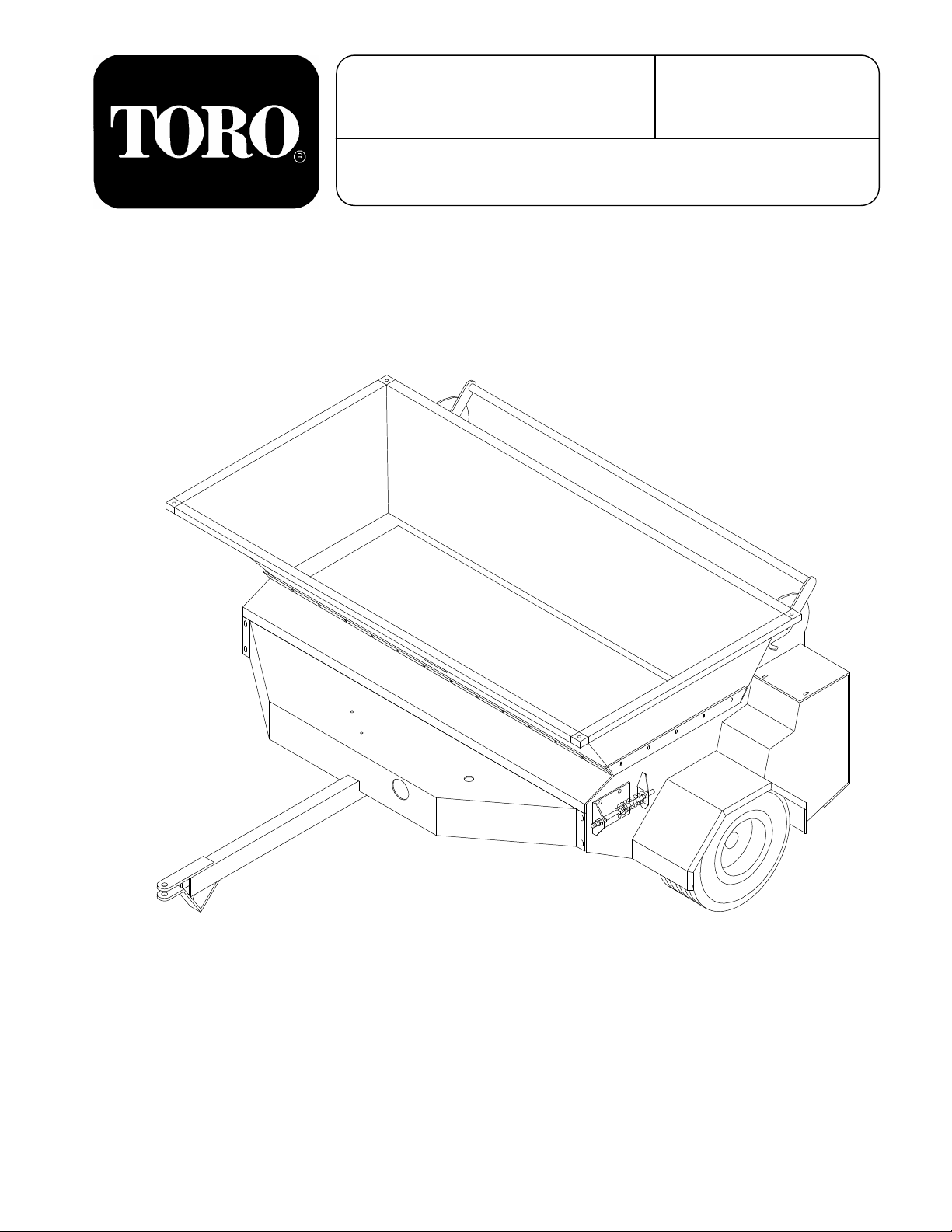
OPERATOR’S
MANUAL
MODEL NO. 44501 - 70001 & UP
TOPDRESSER 2300
FORM NO. 95-4836
The TORO Company - 1997
©
All Rights Reserved
Page 2

FOREWORD
Thank you for bu ying a h igh quality Toro tu rf care product. To g et the b est performan ce fro m this m achine,
operate and maintain it according to the instructions in this manual.
Toro also wa nts to stress the importance o f safety. You and anyone else using or main taining this machine
are strongly urged to read this ma nual, esp ecia lly all the saf ety inst ruct ion s.
DANGER, WARNING and CAUTION, used with the triangular safety alert symbol, highlight safety
messages. Alwa ys read and understand these me ssages becau se they relate to personal inju ry and your
safety .
If you ever need help or have questions about your new Toro turf care prod uct, contact your local Au thorized
Toro Distributor. Th e Toro Distributor has a complete supply of replace ment parts, a full line of accessories
and a professional service staff to support you. Keep your Toro all Toro. Buy genuine Toro parts and
accessories.
2
Page 3
TABLE OF CONTENTS
Page Page
SAFET Y INSTRUCT IO N S. . . . . . . . . . . . . . . 3 - 4
SAFETY AND INST RUCT I O N DECALS. . . . . . 4
LOOSE PARTS . . . . . . . . . . . . . . . . . . . . . . . . . . 5
SPECIFICATIONS. . . . . . . . . . . . . . . . . . . . . . . 6
SET UP INST RUCTIONS
Install Tongue . . . . . . . . . . . . . . . . . . . . . . . . . . 7
Assemble Hopper . . . . . . . . . . . . . . . . . . . . . 7
BEFORE OPERATING
Check Hydraulic System. . . . . . . . . . . . . . . . . 8
Check Tire Pressure . . . . . . . . . . . . . . . . . . . . . 8
Attach Topdresser To Towing Vehicle. . . . . . 8
CONTROLS. . . . . . . . . . . . . . . . . . . . . . . . . . . 8 - 9
OPERATING INSTRUCT IO NS . . . . . . . . . . . . . . 9
LUBRICATION. . . . . . . . . . . . . . . . . . . . . . . . . . 10
SAFETY INSTRUCTIONS
The safety alert symbol means
CAUTION, WA RN ING or DANGER "personal safety inst ru ct ion ". Read
and understan d the ins truc tio n
because it has to do with safety. Failure to
comply with the instruct ion ma y result in
personal injury.
BEFO RE OPERATING
1. Read and understand all operating and safety
instructions. Before operating this unit, become
familiar with all controls and know how to stop
quickly. A replacement manual is available by
sending complete Model and Serial Number to:
MAINTENANCE
Bleeding Hydraulics. . . . . . . . . . . . . . . . . . . . . 11
Changing Oil Filter. . . . . . . . . . . . . . . . . . . . . . 11
Oil Tank . . . . . . . . . . . . . . . . . . . . . . . . . . . . . . 11
Wheel Motor Nut Torque . . . . . . . . . . . . . . . . . 11
Brush To Conv eyor Belt Adjustment . . . . . . . 12
Chain Tension . . . . . . . . . . . . . . . . . . . . . . . . 12
Rotation . . . . . . . . . . . . . . . . . . . . . . . . . . . . . 12
Conveyor Bel t Instal lat i on/T e n sion . . . . . . . . . 13
ELECTRIC SCHEMAT IC . . . . . . . . . . . . . . . . 14
HYDRAULIC SCHEMATIC . . . . . . . . . . . . . . . 15
TROUBLE SHOO TING . . . . . . . . . . . . . . . 16 - 17
STORAGE . . . . . . . . . . . . . . . . . . . . . . . . . . . . . 18
IDENTIFICATION AND ORDERING . . . . . . . . . 18
MAINTENANCE CH ART . . . . . . . . . . . . . . . . . . 19
WARRANTY. . . . . . . . . . . . . . . . . . . . Back Cover
WHIL E OPERATING
5. NEVER o pen the hydrau lic oil c ap until A LL air
pressure has been released.
6. The weight of the topdresser when filled with
sand is approximately 3500 lbs. The towing
vehicle should have adequate brakes to handle
this weigh t. Ch eck the spe cif ication s in t he to wing
vehicle’s operator manual pertaining to towing
weight.
7. NEVER carry passe ngers on t he mach ine, a nd
keep everyone away from the areas of operation.
The Toro Company
8111 Lyndale Avenue South
Minneapolis, MN 55420
8. NEVER allow child ren t o opera te th e machin e.
Do not allow adults to operate the mach ine without
proper instructions.
9. Make sure all hydraulic fittings are tight and all
2. Before each us e, be sure all bolt s and nut s
are tight.
3. Do not modify this equip men t in an y man ne r.
hydraulic hoses are in good condition before
operating this unit.
10. Keep hands and feet out of hopper when unit
is operating or engine is running on to wing vehicle.
4. W h en guards are removed f or se rvice, replace
them before operating machine. Guards are for
your protection.
3
11. To avoid loss of control, NEVE R , tow the unit
faster than 12MPH.
Page 4

SAFETY INSTRUCTIONS
MAINTENANCE
Hydraulic fluid esca ping under pre ssure c an h ave
sufficient force to penetrate skin and do serious
12. NEVER open the hydraulic cap until ALL air
pressure has been released.
damage. If fluid is injected into skin it must be
surgically removed within a few hours by a doctor
familiar with this form of injury or gangrene may
13. Keep body and hands away from pin hole
result.
leaks or nozzles that eject hydraulic fluid under
pressure. Use paper or cardboard, not hands to
search for leaks.
14. ALWA YS torque the nut on the wheel motors
to 230 - 250 ft. lbs when servicing .
SAFETY AND INSTRUCTION DECALS
The following safety and instruction decals are installed on the unit. Replace any decals that becomes
damaged or illegible. Part numbers for decals are listed below and in your Parts Catalog. Order
replacements from your Authorized Toro Distributor.
LINED UP WITH GATE
CONTROL POINTE R
(Part No. 01-506-0210)
OVER OIL CAP
(Part No. 01-506-0250)
NEAR BEARINGS &
GATE CONTROL ARM
(Part No. 58-6520)
ON CHAIN GUARD
(Part No. 01-506-0050)
ON FENDERS & HYD. TANK
(Part No. 75-5190)
EACH SIDE OF HOPPER
(Part No. 01-506-0240)
4
Page 5

LOOSE PARTS
Description Qty Use
Tongue 1 Install tongue
Capscrew, 1/2"-13 x 3-1/2" 2
Flat Washer, 1/2" 4
Hex Nut, 1/2" 4
Hopper Front 1 Assemble ho pper
Long Skirt 1
Carriage Bolt, 1/4" -20 x 1" 20
Flat Washer, 1/4" 40
Lock Washer, 1/4" 40
Hex Nut, 1/4" 40
Short Skirt 2
Hopper Side, LH 1
Hopper Bac k 1
Hopper Bra ce 1
Carriage Bolt, 1/4" -20 x 3/4" 20
Hopper Side, RH 1
Support Rod 2
Hex Nut, 3/8" 4
Flat Washer, 3/8" 2
Wiring Harness 1
5
Page 6

SPECIFICATIONS
Dimensions:
Height: 40"
Length: 88"
Width: 83"
Hopper Dimensions:
Height: 18-1/ 4"
Top Width: 76"
Bottom Width: 60"
Top Length: 40"
Bottom Length: 20"
Hopper Capacity: 23.5 cubic foot
Spreading Width: 60"
Top D ressing Sp eed: Up to 8 MPH
Transporting Speed: Up to 12 MPH
Conveyor Belt: Continuous 60 " wide comp os i -
tion belt with heavy du ty polye st er cord.
Metering Gate: Infinitely variable from clo sed to
4-1/2" openin g for ligh t to heavy ap plic ation s.
Controls: 12 volt on/off switch at operat or’s po-
sition to engage conveyor and brush. Metering
gate control arm spans full width in fron t of
brush.
Drive: Ground driven hydraulic system self-con-
tained to topdresser (no hoses to connect to
towing vehicle).
Wheels and tires:
(4) 16 x 6.50 x 8 and
(2) 18 x 8.50 x 8 - 4 ply rib tread, high
flotation tires
Hydrau lic O i l: 10W30 SF - CC (2 gallons)
Air pressure:
Tires: 20 PSI
Hydraulic tank: 20-4 0 PSI
Shipping Weight: 1000 lbs.
6
Page 7

SET UP INSTRUCTIONS
Figure 1
INSTALL TONGUE (Fig. 1)
1. Mount the tongue using (2) 1/2" x 3-1/2" bolts,
flat washers and nuts provided. Double nut both
bolts.
ASSEMBLE HOPPER (Fig. 2)
1. Assemble th e sides, front, and back (Item A, B,
and C) of the hopper and corner guards
(Item H) using the 1/4" x 3/4" carriage
bolts provided. Attach at all four
corners and secure tigh tly.
2. Set the hopper frame in position on the
topdresser.
3. Attach the rear rubber skirt (D) between the
frame and the hopper. Use the 1/4" x 1" carriage
bolts to mount.
4. Attach the side rubber skirts (E) between the
frame and the hopper. Make sure rubber seals
together on sides , th en tigh te n bolts.
C
E
D
IMPORTANT: The rubber flaps must be installed on the topdresser. If the flaps are not
installed, damage will occur to the conveyor
belt and rollers.
5. Install support rods (F) through the front side.
Install the hopper brace (G) on the rear of the
hopper. Run the threaded end of the support rod
through the brace and the hopper. Attach with a
3/8" fl at washe r an d doub le nut.
G
H
B
H
A
C
F
E
Figure 2
7
Page 8

BEFORE OP E RATING
Open
Close
Gate Control Arm
Black
Knob
Gate
CHECK TIRE PRESSURE
DANGER
Pressurized Cap Can Cause Seriou s In jury
If Improperly Opened.
Never open oil cap without releas ing
pressure valve stem.
Keep face and upper body away from cap
while opening.
CHECK HYDRAULIC SYSTEM
1. The hydraulic sy stem is design ed to operate on
10W30 SF-CC oil. The tank contains 2 gallons of
oil. There should be 4" of oil in th e tank whe n full.
2. Pressurize the hydraulic tank with air (20 to 40
PSI). Always maintain air pressure in the tank to
minimize slipping of the conveyo r belt whe n using
heavy or wet sand.
3. Visually inspe ct th e hydra ulic s ystem for leaks,
loose fasteners, missing parts, improperly routed
lines. Make all repairs before operating.
1. Check tire pressure before e ac h use. Be ca use
the topdresser is ground driven always maintain
tire pressure at 20 PSI.
ATTACH TOPDRESS ER TO TOW ING
VEHI CLE
1. Attach the topdresser to the towing vehicle.
Use the pin on the towing vehicle to secure.
2. Connect the long half of the wiring harness to
short half at the end of the tongue.
3. Connect th e red w ire to the posit ive te rminal on
the towing vehicle battery. The white wire
connects to the negative te rmina l.
4. Gather and consolidate all loose wires. Tape
together with existin g wires on the towing vehicle.
Make sure there a re no loos e or dan glin g wire s to
interfere with the operation of the unit.
5. Pull the unit forward at a slow speed and flip the
electric al switch to t he "O N " po sit ion . If b rush a nd
conveyor belt rotate flip switch off. If they do not
rotat e, chec k the t roub le shoo ting pa ge (pg. 16) f or
details. After checking, turn the switch off.
CONTROLS
ELECTRIC SWITCH
The electric switch has 2 positions; ON, OFF.
When switch is on the conveyor belt and brush will
rotate. When switch is off the conveyor belt and
brush stop rotating.
GATE CONTROL ARM (Fig. 3)
The gate control arm is used to control the amou nt
of sand being applied to the turf. The black knob
on the end is used t o loc k t he s et tin g int o position.
1. Loosen t he black knob e nough to allo w the arm
to pivot.
8
2. Set the gate into position. Moving the gate
control arm downwa rd opens the gate and upward
motion closes it.
3. When desired gate setting is obtained, tighten
black knob to lock into position.
Figure 3
Page 9

CONTROLS
DANGER
Pressurized Cap Can Cause Seriou s In jury
If Improperly Opened.
NEVER open oil cap with out rele asin g
pressure valve stem.
Keep face and upper body away from cap
while opening.
OPERATING INSTRUCTIONS
DANGER
NEVER carry passengers on the machin e or
towing vehicle, and keep everyone away from
the areas of ope ration.
To avoid loss of control, NEVER, tow the unit
faster than 12 MPH.
Keep hands an d f e et out of hopp er wh en uni t
is operating or engin e is running on towing
vehicle.
1. Fill the hopper with sand. The maximum
amount of san d that can be put into the hopper is
2500 pounds. The weight of the topdresser filled
with sand is approximately 3500 pounds. The
towing vehicle should have adequate brakes to
handle this we ight. Check the spe cific ations in t he
towing vehicle’s operator manual pertaining to
towing weight.
IMPORTANT:
faster 12 MPH because the hydraulic motors
will be damaged.
NEVER transport at a speed
PRESSURE GAUGE
The gauge i s a p r es s ur e gauge that read s the ai r
pressure in the tank. The recommended air
pressure is between 20 - 40 PSI.
2. Ope n t he gat e a rm t o th e de si re d ra te . Tig ht en
the black knob to lock into posit ion .
3. Slowly pull the topdresser forward and flip the
electrical switch to the "ON" position. The unit is
now topdressing.
4. Flip electric switch to OFF to stop topdressing
and before tran sp ortin g.
SAND APPLICATION RATE
The rate of sand being applied depends on the
weight of the sand. Sand varies in moisture and
coarseness which effects the weight. These
factors must be taken into consideration when
determining the amount of sand required for the
application. Test a small area to determine the
correct amount.
IMPORTANT: The maximum amount of sand
that can be put into the hopper is 2500
pounds.
NEVER top dress at a speed faster than 8
MPH.
9
Page 10

LUBRICATION
Figu re 5
BEARINGS (Fig. 4)
The topdresser has 5 self sealing bearings that
must be lubricated with a No. 2 Lithium based
grease.
IMPORTANT: Lubricate the bearings to
maintain a slight leakage on the seals. Too
ADJUSTMENT LUGS (Fig. 5)
Always maint ain a light coat of No. 2 Lithium based
grease on the thread s of the fou r adju stme nt lu gs .
much grease can cause overhe ating.
Figure 4
Wheels
Grease fit tings weekly or eve ry 40 operating hours.
Use No. 2 Lithium based grease.
DRIVE CHAIN
Always main tain a light coat o f gre ase o n the drive
chain.
10
Page 11

MAINTENANCE
BLEEDING HYDRAULIC SYSTEM
DANGER
Pressurized Cap Can Cause Seriou s In jury
If Improperly Opened.
Never open oil cap without releas ing
pressure valve stem.
Keep face and upper body away from cap
while opening.
When any hydraulic part is rep laced the system will
have to be bled.
1. Push va lve s te m in to re lea se all press ure f rom
the ta nk.
2. Remove the air pressure cap.
must run smoothly with no jerking motion .
6. When all are operating smo othly, inst all th e air
pressure cap. Check the air pressure cap for
leaks. See Check Hydraulic Syste m under Befo re
Operating (pg. 8).
IMPORTANT: When working with hydraulics,
you must keep the work area as clean as
possible. Change oil and filter as
recommended. If you have a new piece of
equipment under warranty and a hydraulic item
goes out . . . . don’t try to fix it. Install a new
part and return the de fective part to the factory.
It is easier to get warran ty on a part that has n ot
been taken apart.
CHANGING OIL FILTER
The oil filter is a 10 micron cross f ilter. Change the
filter every 100 hours of operation. Always fill the
element with oil when inst allin g a new filte r.
3. With towing unit, pull the topdress er up to
8 MPH. Pull the top dresser until all "jerking"
motion has stopped.
4. Use a tape measure to check the level of oil in
the ta nk .
Tabs
Torque
230 - 250 ft. lbs.
5. Check the conveyor and brush motors, both
Figure 6
OIL TANK
The oil tank is a 2 gallon capa city tank. Th e oil type
is 10W30 or 10W40 SF - CC (preferably 10W30).
Change oil every 500 hours or yearly, whichever
comes first. The drain plug is located on the
bottom of the tank.
IMPORTANT: When adding oil to the system
pour it through a funne l with a fine mesh screen
(200 mesh or better). Keep the funnel and
containers immaculately clean. This
procedure prevents accidental contamination
of the hydrauli c system.
WHEEL MOTOR NUT TORQUE (Fig. 6)
ALWAYS torque the nut on the whee l motor to 2 30
- 250 ft. lbs when servicing. Place the tabs of the
nut on the outside as shown in Fig. 6. If the tabs
are insta lled on the insid e, again st the h ub, the nut
cannot be torqued properly.
11
Page 12

MAINTENANCE
(A)
Figu re 9
BRUSH TO CONVEYOR BELT ADJUSTMENT
Fig. 7)
The brush is moved back and forth on its mounting
slots to adjust it to the conveyor belt. The brush
should be as close to the belt as possible without
touching. A piece of paper can be inserted
between t he conveyor b elt and t he b rush to check
CHAIN TENSION (Fig. 8)
The cha in tens ion i s a dju sted by mov ing the mot or
Brush
Bearing
Right Side Left Side
Figure 7
Brush
Brush
Motor
the adjustment. The brush must be the same
height from end to end.
1. Loosen the nut s of the bearing on the right hand
side.
2. Lo osen the nu ts mo unti ng th e brus h mot or to
the main frame.
3. Slide the brush into position on the right hand
side. Finger tig hten the nuts.
Figu re 8
and sprocket assembly (A) up and down on its
mounting slots. A 1/8" deflection is
recommended. Do not over tigh ten, this will ca use
chain we ar. Do not operat e with a loose chain; thi s
will cause sprocket wear.
1. Loos en the nut s mo untin g the mot o r an d
sprocket as semb ly (A) to the main frame.
2. Slide the hydraulic mot or and sproc ket
assembly (A) u p and down on the mountin g
slot until proper te nsio n is achiev ed .
3. Tighten the nuts.
4. Slide the brush into position on the left hand
side. Finger tig hten the nuts.
5. Insert a piece of paper between the brush and
the conveyor belt. The brush must be the same
height from end to end.
6. If the adjustment is correct, tighten the nuts. If
not, repeat steps 1 through 5.
12
ROTATION (Fig. 9)
Rotation
Direction
The rotat ion of the con veyor, brush an d the wheel s
Page 13

is shown in Fig. 9 . If the ro tatio n in not cor rect, t he
4.5 "
A
Figure 11
hydraulic line s are inst alle d backwa rds. See the
MAINTENANCE
CONVEYOR BELT INSTALLATION/TENSION
(Fig. 10 & 11)
To install a new conveyor belt follow the
instructio ns be low.
1. Pull the topdresser forward until the conveyor
belt seam is in the center of the hopper.
2. Loosen t he nuts (A) on the spring rod to rele ase
the tension .(See Figure 11).
3. Remove the lacing (seam wire) from the old
conve yo r be l t.
4. Grab one sid e o f the o ld con ve yor belt and pul l
it free from the unit.
5. Lay the new belt on th e frame and roll it arou nd
the rollers bringing th e seam to the center.
Hydraulic Schematic (pg. 15).
CONVEYOR BELT LACING
The lacing on the conveyor belt has a silicone
sealer on it to prevent sand leakage inside the
conveyor belt. Re apply once a year and everytime
the lacing is removed for service. The silicone may
be purchased locally. It is multi-purpose, weather
resistant and should be flexible or flowable.
1. Tigh ten the nu t on the spring rod until t he spring
is compressed to 4-1/2" as shown in Fig. 11. Be
sure the front roller is parallel with the drive roller.
This can be done by measuring the distance
between the drive roller bearing bolt and the idler
roller bearing bolt on each side. If there is a
difference tighten the nut on the spring rod until
6. Feed the lacing through the conveyor belt
seam. Make sure the lacing is lined up. If the
lacing is of f one notch it will cause the belt t o buckle
and not run s traight . Ch eck f or straig htne ss with a
straight edge once it has been installed. See Fig.
10. After the wire is centered, bend both ends of
Straight Edge
the wire to prevent the wire from working loose.
Figure 10
distance on both sides is equal.
2. Tighten the jam nut against the other jam nut.
The plate mu st be free to slide . Tig ht en the bolts,
then loosen until it can slide.
IMPORTANT: Do not allo w the plate to beco me
too loose, it will cause the spring rod to bend.
13
Page 14

ELECTRICAL SCHEMATIC
Black
or
White
Red
Black
or
White
Fuse
3 Amp.
BATTERY
White
Red
SWITCH
White
ELECTRIC
SOLENOID
HYD. VALVE
14
Page 15

HYDRAULIC SCHEMATIC
FILTER
Return
WHEEL
MOTOR
T1
A
C
To Motor When ON
T2
B
WHEEL
MOTOR
LOWER DRIVE
SPROCKET
MOTOR
BRUSH
MOTOR
Suction
Suction
HYDRAULIC
TANK
15
Page 16

TROUBLE SHOOTING
CONDITION CAUSE CORRECTION
Conveyor Belt and Brush Not
Turning
Conveyor Belt Not Turning
•
Bad Electrical Connections
•
Blown harne ss fuse.
•
Hydraulic lines installed backwards
•
Contaminated valve
•
Loose or broken chain
•
Tension of the belt is too loose.
•
Plug in the wiring harness and
make sure wires are making
contact.
•
Replace fuse
•
Standing on the left hand side
(Chain Guard side) the conveyor belt should rotate clockwise and the brush should rotate counterclockwise. If incorrect, reverse the lines on
the corresponding motors.
•
Remove cartridge to see if
blocked. Clean out, making
sure plunger is not damaged.
Replace valve or cartridge.
•
Replace chain or adjust tension.
•
Tighten the tension.
Tire(s) Skidding
•
Brush set too low to the belt.
•
Drive roller not turni ng
•
One tire skids
•
Both tires skid
•
Slide a sheet of paper between the brush and the belt;
it should slide freely. If brush
is too low slide it upwards until it clears the belt just
enough to slide the paper underneath. Make sure the paper clears at the lacing.
•
Check the welds on each end
of the drive roller. The shaf t
may be turning but not the
roller. Replace drive roller.
•
Check sprocket for sheared
key. Replace key.
•
Replace the check valve on
that side.
•
Check the valve for blockage
of ports.
16
Page 17

TROUBLE SHOOTING (Cont.)
17
CONDITION CAUSE CORRECTION
Tire(s) Skidding (co nt .) •
•
Uneve n ti re pressure
Conveyor Belt Not Tracking
Properly
•
Belt pulls to one side
•
Belt Buckles in Center
•
Belt rides off pulley
Check the pressure setting on
the relief valve (1100 PSI) it
may be too low. Reset, if necessary.
•
Check tire pressure. All tires
should be 20 PSI.
•
Tension is not the same from
side to side. Set the spring
rod at 4 1/2" on both sides.
Run. The belt will pull to the
tight side. Loosen or tighten
as needed.
•
Pulleys are not in line. Remove belt lacing and realign
the pulleys using straight
edge or fixture.
•
V-Guides of the belt not correct. Measure distance between v-guides for straightness and squarness. Tolerance for both is (+) or (-) 1/16".
Uneven Sand Distrib u tion
•
Uneve n ti re pressure
•
Uneve n brush setting
•
Excessive air in the system
•
Not enough air in oil tank
•
Check both outside tire pressure; both tires should be 20
PSI.
•
Check brush to conveyor belt
adjustment. Brush should be
same height all the way
across face.
•
Bleed lines. See Operators
Manual for instructions.
•
Pressurize air in tank to 35
PSI.
Page 18

SEASONAL STORAGE
1. Thoroughly clean the topdresser, especially
inside the hopper . The hopper and conv eyor belt
area should be free of any remaining sand
particles.
2. Apply a light coat of silicone to the lacing of the
conveyor belt. Refer to Mainten ance se ctio n
3. Inflate all tires to 20 PSI. Or block up the
topdresser to remo ve the weig ht.
4. Drain and replace hydraulic fluid and filter.
Inspect all hydraulic lines and fittings. Replace if
necessary. Refer to the Maintenance section.
5. Tighten all fasteners.
IDENTIFI CATION AND ORDERING
6. Lubricate all grease fittin gs and bearings. Wipe
off exces s lubrica nt . Refer t o page 10.
7. The unit should be stored out of the sun to
prolong the life of the conveyor belt. If stored
outside it is recommen ded to cover the hopper with
a tarp.
8. Check t he tension of the drive chain . Adjus t the
tension if necessa ry and lig htly co at the chain with
grease. Ref er to the M aintenance sect ion (pg. 11
- 13).
MODEL AND SERIAL NUMBER
The TOPDRESSER 2300 has two identification
numbers: a mod el number and serial number. The
two numbers are stamped on a plate which is
riveted on the hydraulic tank. In any
correspondence concerning the TOPDRESSER
2300, supply mo del and serial n umbers t o be su re
that the correc t info rmation an d replace ment part s
are obtain ed .
To order replacement parts from an authorized
TORO Distributor, supply the following
information:
1. Model and serial numbers of the mach ine .
2. Part number, description and quantity of parts
desired.
Note: Do not order by re feren ce nu mbe r if a part s
catalog is being use d; use the pa rt nu mbe r.
18
Page 19

MAINTENANCE RECORD
19
Page 20

The Toro Commercial Products Two Year Limited Warrant y
The Toro Company warrant s your 1996 or n ewer Toro Co mmercial Product ("P roduct") purchased after
January 1, 1997, to be free from defects in materials or workmanship for the period of time listed below*. Where
a warrantable condition exists, Toro will repair the Product at no cost to you including diagnosis, labor, parts,
and transportation. This w arranty begins on the date the Product is delivered to the original retail purchase r.
Warranty Duration: Two years or 1500 operational hours*, whichever occurs first.
* Product equipped with hour meter.
Owner Responsibilities:
As the Product owner, you are responsible for required
maintenance and adjustments stated in your Owner’s
Manual. Failure to perform required maintenance and
adjustments can be grounds for disallowing a warranty
claim .
Instructions For Obtaining Warranty Service:
You are responsible for notifying the Commercial Products
Distributor or Authorized Commercial Products Dealer from
whom y ou purchase d the Produ ct as soon as yo u believe a
warrantable condition exists.
If you need help locating a Commercial Products Distributor
or Auth orized De aler, or if you have questio ns regardin g your
warranty rights or responsibilities, you may contact us at:
Toro Commercial Products Service Department
8111 Lyndal e A venue Sout h
Minneapolis, MN, 55420-1196
Telephon e: (612) 88 8- 8 801
Facsimile:(612) 887-8258
E-Mail: Commercial.Service@Toro.Com
Maintenance Parts:
• This warranty does not apply to parts subject to consumption
thr ough u se unless f ound t o b e def ective . Ex amples of p arts
which are consumed, or used up, during normal Product
operation include, but are not limited to, blades, reels,
bedknive s, tines, spark plug s, castor wheels, tires, filters,
belts, etc.
• This wa rranty does not apply to fail ures caused by outside
influence. Items considered to be outside influence include,
but are not limited to, weather, storage practices,
contamination, use of unapproved coolants, lubricants,
additives, or chemicals, etc.
• This warran ty does not ap ply to nor mal "wear and tear" it ems.
Normal "Wear and Tear" includes, but is not limited to,
damage to seats due to wear or abrasion, worn painted
surfaces, scratched decals or windows, etc.
Other Legal Disclaimers:
The above remedy of product defects through repair by an
authori z ed di stributor or deale r i s th e p urchaser’ s sole re me dy
for any defect. This w arranty gives you specific legal rights,
and you may also have other rights which vary from state to
state.
Except for the Emissions warranty referenced below,
if applicable, there is no other express warranty. All
implied warranties of merchantability and fitness for
use are limited to the duration of the express warranty.
Parts scheduled for replacement as required maintenance
("Maintenance Parts"), are warranted for the period of time
up to the scheduled replacement time for that part.
Items/Conditions Not Covered:
Not all product failures or malfunctions that occur during the
warranty period are defects in materials or workmanship.
The items / conditions listed below are not covered by this
warranty:
• Product failures which result from the use of non-Toro
replacement parts, or from installation and use of add-on,
modified, or unapprov ed acce ss ories are not covered .
• Product failures which result from failure to perform required
maintenance and/or adjustments are not covered.
• Product failur es which result from operating the Product in an
abusive, negligent or reckless manner are not covered.
Some sta te s do not all ow l imitation s o n how long an imp l ie d
warranty last s, so the above limi tation may not apply t o you .
The Toro Company is not liable for indirect, incidental
or consequential damages in connection with the use
of the Product, including any cost or expense of
providing substitute Product or service during periods
of malfunction or non- use.
Some states do not allow the exclusion of incidental or
consequential damages, so the above exclusion may not
apply t o you.
Note to California residents:
Syste m on yo ur Pr oduc t may b e co vered by a separ ate wa rran ty
meeting requirements e stablished by the U.S. Environme ntal
Protection Agency (EPA), or the California Air Resources Board
(CARB). The ho ur limitation s set for th above do not ap ply to
the Emissions Control System Warranty. Refer to the California
Emissio n Control Wa rranty State ment pri nted in your Ow ner’s
Manual or contained in the engine manufacturer’s
The Emissions Control
 Loading...