

Page 1

Page 2

TTaabbllee ooff CCoonntteenntts
s
PPaagge
e
TTMMRR--11 RReemmoottee CCoonnttrrooll SSyysstteemm OOvveerrvviieew
HHaannddhheelldd TTrraannssmmiitttteerr CCoommppoonneenntts
RReecceeiivveerr CCoommppoonneenntts
RReecceeiivveerr IInnssttaallllaattiioon
s
. . . . . . . . . . . . . . . . . . . .4–5
n
. . . . . . . . . . . . . . . . . . . . . .6–9
w
. . . . . .1
s
. . . . . . . . .2–3
s Indoor Installation . . . . . . . . . . . . . . . . . . . . . . . .6
s Outdoor Installation . . . . . . . . . . . . . . . . . . . . . . .8
RReemmoottee CCoonnttrrooll OOppeerraattiioonns
s
. . . . . . . . . . . . . .10–12
s Basic Station Operation . . . . . . . . . . . . . . . . . . .10
s Operating Controls . . . . . . . . . . . . . . . . . . . . . .11
s ASC Operation . . . . . . . . . . . . . . . . . . . . . . . . . .12
TTMMRR--11 SSeettuupp FFeeaattuurrees
s
. . . . . . . . . . . . . . . . . .13–15
s Set Transmitter to Receiver’s Address Code . . . .14
s Reset Receiver Address Code . . . . . . . . . . . . . . .14
s Adjust Station Number Range . . . . . . . . . . . . . .15
TTrraannssmmiitttteerr BBaatttteerryy SSeerrvviicce
e
. . . . . . . . . . . . . .16–17
s Charging the Batteries . . . . . . . . . . . . . . . . . . . .16
s Replacing the Batteries . . . . . . . . . . . . . . . . . . . .17
TTrroouubblleesshhoooottiinng
SSppeecciiffiiccaattiioonns
WWaarrrraannttyy IInnffoorrmmaattiioon
IImmppoorrttaanntt OOppeerraattiinngg IInnffoorrmmaattiioon
g
. . . . . . . . . . . . . . . . . . . . . . .18–19
s
. . . . . . . . . . . . . . . . . . . . . . . . . . . .20
n
. . . . . . . . . . . . . . . . . . . . .21
n
. . . . . . . . .21-22
i
iii
TTMMRR--1
1
TTaabbllee ooff CCoonntteenntts
S
s
Page 3

TTMMRR--11 RReemmoottee CCoonnttrrooll SSyysstteemm OOvveerrvviieew
w
The Toro Maintenance Remote is designed for convenience
and usability. This powerful tool enables a single operator
to perform most manual controller operations remotely
from the field.
With the capacity to handle commercial
and municipal applications, the TMR-1 is also right at
home in residential systems as well.
The TMR-1 kit includes a long-range, handheld transmitter
complete with NiMH batteries and compatible charger.
A pre-wired, quick-release receiver mount enables the
TMR-1 system to be quickly installed and ready for operation; then easily moved from site to site as needed.
The TMR-1 system
is designed for simple “plug and play”
operation with all Toro and Irritrol remote-ready controllers,
such as, TMC-212, TMC-424, and Rain Dial
®
Plus.
For additional controller model compatibility information,
refer to “Specifications” on page 20.
FFeeaattuurreess aanndd BBeenneeffiittss
s
Programmable handheld transmitter retains up to
999 unique receiver address codes.
s
Handles high station-count controllers — provides
remote control of up to 512 individual stations.
s
Quick-release receiver mounting system — enables
receiver to be moved easily from site to site.
s
Rechargeable NiMH batteries and dual-rate charger —
keeps batteries at peak efficiency.
s
Remote operations include: start, pause/resume, skip,
restart and stop functions of selected stations and fully
automatic ASC (All Station Cycle) for quick-check
system operation.
IIMMPPOORRTTAANNTT::BBeeffoorree iinnssttaalllliinngg aanndd ooppeerraattiinngg tthhiis
s
eeqquuiippmmeenntt,, rreeaadd aallll pprroodduucctt uussee aanndd ssaaffeettyy iinnffoorrmmaattiioon
pprroovviiddeedd oonn ppaaggeess 2211 aanndd 2222 ooff tthhiiss mmaannuuaall.. FFaaiilluurree tto
o
ccoommppllyy mmaayy rreessuulltt iinn iinnjjuurryy aanndd//oorr eeqquuiippmmeenntt ddaammaaggee.
TTMMRR--1
1
SSyysstteemm OOvveerrvviieew
S
w
n
.
1
1
Page 4

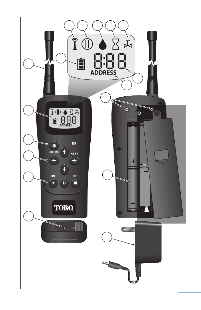
HHaannddhheelldd TTrraannssmmiitttteerr CCoommppoonneennttss
11--AAnntteennnnaa -22--LLCCDD DDiissppllaayy SSyymmbboollss::
AA--TTrraannssmmiitt -BB--PPaauussee -CC--WWaatteerr OOnn -DD--TTiimmee -EE--SSttaattiioonn --
FF--NNuummeerriicc DDiissppllaayy CChhaarraacctteerrss
GG--AAddddrreessss --
HH--BBaatttteerryy SSttaattuuss--
33--AAddddrreessss KKeeyy --
44--CCuurrssoorr KKeeyyss -
number. Left/Right arrow keys step through station
sequence during operation.
55--FFuunnccttiioonn KKeeyyss -
66--BBaatttteerryy CChhaarrggeerr RReecceeppttaacclle
Screw-mount, flexible whip.
Indicates signal transmission
Indicates watering on hold
Indicates station watering on
Indicates run time is displayed
Indicates station number is displayed
Indicates address function is displayed
Indicates battery charge status
Accesses receiver address code function
-
Up/Down arrow keys select station
-
Accesses On, Pause and Off functions
e
77--BBeelltt CClliipp AAttttaacchhmmeenntt PPooiinnttss
(belt clip not shown)
88--NNiiMMHH BBaatttteerryy SSttaacckk
99--111155 VVAACC//77..55 VVDDCC BBaatttteerryy CChhaarrggeerr
2
2
TTMMRR--1
1
TTrraannssmmiitttteerr CCoommppoonneenntts
S
s
Page 5
B
B
C
A
A
H
1
1
2
2
3
3
4
4
5
5
H
C
E
E
D
D
F
F
G
G
7
7
8
8
6
6
9
9
3
TTMMRR--1
1
TTrraannssmmiitttteerr CCoommppoonneenntts
S
3
s
Page 6

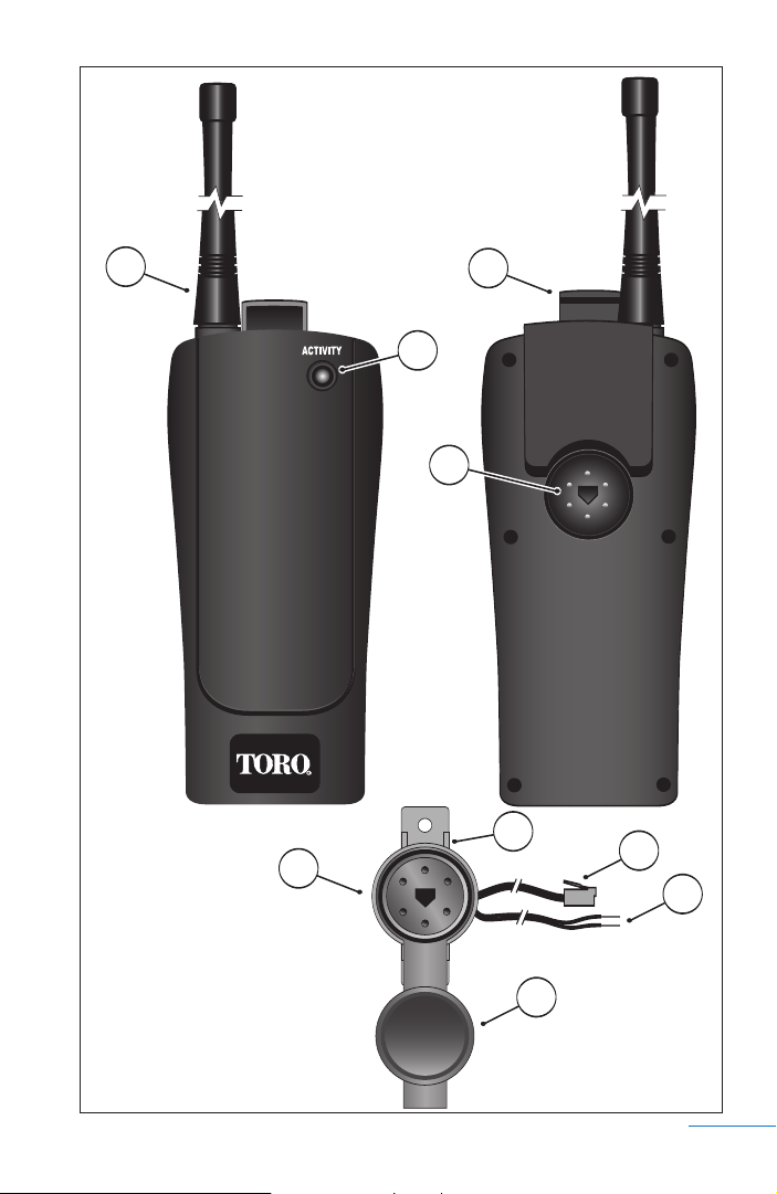
RReecceeiivveerr CCoommppoonneennttss
11--AAnntteennnna
22--RReecceeiivveerr LLoocckk --
a
Sliding latch secures the receiver to
the plug assembly.
33--AAccttiivviittyy MMoonniittoorr LLEEDD --
Flashes Green while power is
applied; Red when receiving a valid signal from the
transmitter.
44--RReecceeiivveerr PPlluugg RReecceeppttaacclle
55--RReecceeiivveerr PPlluugg MMoouunnttiinngg BBrraacckkeett --
e
Enables simple
wall-mount installation. Easily removed enabling
receiver plug installation in threaded
66--RReecceeiivveerr PPlluugg AAsssseemmbblly
y
77--MMoodduullaarr RRJJ--1111 PPlluugg aanndd CCaabbllee AAsssseemmbbllyy --
1
⁄2" PVC.
Connects
the receiver to a compatible, remote-ready controller.
88--RReecceeiivveerr PPoowweerr WWiirreess --
Connects the receiver to the
controller’s 24 VAC power terminals.
99--RReecceeiivveerr PPlluugg CCoovveerr --
Covers and protects the plug
assembly when the receiver is not installed. Prevents
damage due to prolonged exposure to moisture, sun
and dust.
4
4
TTMMRR--1
1
RReecceeiivveerr CCoommppoonneenntts
S
s
Page 7
1
1
3
3
6
6
2
2
4
4
5
5
7
7
8
8
TTMMRR--1
1
RReecceeiivveerr CCoommppoonneenntts
S
9
9
5
s
5
Page 8

RReecceeiivveerr IInnssttaallllaattiioon
n
Before using your TMR-1 remote control system for the
first time, the following procedures must be completed:
s
Charge the transmitter batteries for a minimum of
8 hours.
s
Install and connect the receiver plug assembly and
receiver unit per the instructions provided.
s
Test the installation to confirm proper signal reception
and remote operation.
For maximum remote control performance and operating
range, select an installation site for the receiver using the
following guidelines:
s
The mounting location wall is constructed primarily of
wood or other non-metallic materials.
s
Stuccoed walls, metal buildings and large metal objects
are avoided.
s
The receiver is located as high above the controller as
possible.
s
The antenna is free of contact and aligned perpendicular
to the horizon.
TThhee TTMMRR--11 rreecceeiivveerr pplluugg aasssseemmbbllyy iiss ssppeecciiffiiccaalllly
ddeessiiggnneedd ffoorr tthhiiss ssyysstteemm.. TThhee TToorroo EEZZ--RReemmoottee aannd
y
d
IIrrrriittrrooll KKwwiikkSSttaarrtt rreecceeiivveerr pplluuggss aarree nnoott ccoommppaattiibbllee..
The receiver plug mounting bracket should be secured to
an inside wall within 4' of the controller (the connecting
cable is approximately 6' in length). Alternately, when an
outdoor installation is preferred, the receiver plug can be
removed from the mounting bracket and installed into a
1
threaded
IInnddoooorr IInnssttaallllaattiioon
1 –
⁄2" PVC pipe fitting.
n
Position the receiver plug assembly on the wall within
4' of the controller, as high as practical. The alignment
hole in the center of the plug must be pointing down.
6
6
TTMMRR--1
1
RReecceeiivveerr IInnssttaallllaattiioon
S
n
Page 9

2–
Using the provided wood screws (or other appropriate
fasteners), secure the bracket to the wall as high as
possible. If installing the plug assembly bracket onto
drywall or masonry, screw anchors must be used.
3–
With the receiver lock pulled up, align and install the
receiver onto the plug assembly. Push the lock down to
engage the groove in the plug assembly. See Figure 1.
CCaauuttiioonn:: NNeevveerr ccoonnnneecctt tthhee rreemmoottee ccoonnttrrool
ppoowweerr wwiirreess ttoo aannyy vvoollttaaggee ssoouurrccee ggrreeaatteerr tthhaann
2244 VVAACC.. FFaaiilluurree ttoo ccoommppllyy wwiillll rreessuulltt iinn sseevveerre
eeqquuiippmmeenntt ddaammaaggee.
4–
Disconnect power to the controller.
5–
Route the receiver plug wiring through the base of the
.
controller cabinet.
FFiigguurree 11
l
e
TTMMRR--1
1
RReecceeiivveerr IInnssttaallllaattiioon
S
7
n
7
Page 10

6–
Locate the controller’s remote RJ-11 jack and insert
the modular connector. See Figure 2.
TThhee ccoonnttrroolllleerr iilllluussttrraatteedd iinn FFiigguurree 22 iiss sshhoowwn
ffoorr rreeffeerreennccee oonnllyy.. RReeffeerr ttoo tthhee ccoonnttrroolllleerr uusseerr’’s
gguuiiddee ffoorr ssppeecciiffiicc iinnssttaallllaattiioonn iinnffoorrmmaattiioonn.
7–
Locate the controller’s 24 VAC connection terminals
.
n
s
and attach the receiver power wires. Connect either
e to either terminal.
wir
8–
Apply power to the controller. The receiver Activity
monitor should begin flashing Green. If the Activity
monitor does not illuminate, confirm the receiver is
properly installed and plug assembly is wired correctly.
OOuuttddoooorr IInnssttaallllaattiioon
n
CCAAUUTTIIOONN:: TThhee rreecceeiivveerr pplluugg iiss wweeaatthheerr rreessiissttaanntt oonnlly
wwhheenn iinnssttaalllleedd iinn PPVVCC ccoonndduuiitt aanndd tthhee pplluugg ccoovveerr iiss iin
ppllaaccee.. TThhee rreecceeiivveerr uunniitt iiss nnoott wweeaatthheerr rreessiissttaanntt aannd
n
d
sshhoouulldd oonnllyy bbee iinnssttaalllleedd oouuttddoooorrss ffoorr tteemmppoorraarryy uussee.. DDo
nnoott aallllooww iirrrriiggaattiioonn sspprraayy ttoo ccoonnttaacctt tthhee rreecceeiivveerr dduurriinng
sspprriinnkklleerr ooppeerraattiioonn.
1–
At the selected installation site, bore a 3⁄4" hole through
the wall for
2 –
Install a length of PVC pipe through the wall, leaving
.
1
⁄2" PVC pipe access.
g
about 1" of pipe on both sides.
3 –
Inside, install a 90° elbow and a 3" section of pipe.
Use a conduit clamp to secure the pipe assembly to
the wall. See Figure 3.
4–
Remove the mounting bracket from the plug assembly.
5–
Insert the receiver plug wiring through the threaded
end of a
1
⁄2" thread/slip PVC fitting. Thread the receiver
plug into the PVC fitting and tighten by hand.
6–
Route the wiring through the conduit. Install the
plug/fitting assembly to the pipe, orienting the plug
alignment hole pointing straight down.
C
–
7
onnect the r
eceiver plug wiring as described above.
y
o
8
8
TTMMRR--1
1
RReecceeiivveerr IInnssttaallllaattiioon
S
n
Page 11

FFiigguurree 22
FFiigguurree 33
TToo CCoonnttrroolllleer
r
9
TTMMRR--1
1
RReecceeiivveerr IInnssttaallllaattiioon
S
n
9
Page 12

RReemmoottee CCoonnttrrooll OOppeerraattiioonns
s
FFoorr tthhee bbeesstt rreessuullttss,, pplleeaassee nnoottee tthhee ffoolllloowwiinngg TTMMRR--1
rreemmoottee ssyysstteemm ooppeerraattiinngg cchhaarraacctteerriissttiiccss:
s
The transmitter batteries must be fully charged prior to
:
operation. Refer to “Charging the Batteries” on page 16.
s
For maximum signal range, hold the transmitter vertically,
at shoulder level, facing toward the receiver when sending
a command. Operating the transmitter in a horizontal
plane and/or contacting the antenna during transmission
can significantly reduce signal range.
s
The highest station number that can be selected is 24 (by
default), but is easily adjusted from 1 to 512 as preferred.
To adjust the station number range, refer to “Adjust
Station Number Range” on page 15.
BBaassiicc SSttaattiioonn OOppeerraattiioon
1–
Press and hold the ON button until the
n
transmitter powers up. The last station
number operated will be displayed on the
initial start up screen. The valve symbol
indicates a station number is shown.
2–
Press the up or down arrow button
to select a station number. Press and hold
the button for rapid scrolling.
3–
Press the ON button. The receiver
Activity monitor will flash Red when a valid
signal is received. The selected station will
turn on and the 10-minute timer will begin
counting down in one-second increments.
The water droplet and the hour glass are
shown to indicate watering in progress.
Every 15 seconds the display will switch to
the operating station number.
TThhee ssttaattiioonn rruunn ttiimmee iiss ffiixxeedd aatt 110
mmiinnuutteess aanndd ccaannnnoott bbee aaddjjuusstteedd.
0
.
1
110
0
TTMMRR--1
1
RReemmoottee CCoonnttrrooll OOppeerraattiioonns
S
s
Page 13

OOppeerraattiinngg CCoonnttrroolls
s
After selecting and starting a station, the following operating
controls become available:
SSttoopp ooppeerraattiioonn:
s
:
Press the OFF button.
SSeelleecctt aa ddiiffffeerreenntt ssttaattiioonn nnuummbbeerr:
s
:
Press the left or right arrow button
to select the station number. The previous
station will turn off as the selected station
starts.
PPaauussee ooppeerraattiioonn:
s
:
Press the pause button. The pause symbol
will be displayed with the station number.
Every 15 seconds the display will alternate to
show the run time remaining when operation
resumes.
Press the pause button again to resume
operation.
IIff tthhee ppaauussee ffuunnccttiioonn iiss nnoott rreelleeaasseedd wwiitthhiinn 110
mmiinnuutteess,, ssttaattiioonn ooppeerraattiioonn wwiillll bbee tteerrmmiinnaatteedd.
RReesseett tthhee ccoouunnttddoowwnn ttiimmeerr:
s
:
Press the ON button. The run time for the
operating station will be reset to 10 minutes.
This control function does not apply to ASC
operation.
TTuurrnn ooffff ttrraannssmmiitttteerr:
s
:
Press and hold the OFF button until the
display is blank.
TThhee ttrraannssmmiitttteerr wwiillll sshhuutt ooffff aauuttoommaattiiccaallllyy aafftteerr 330
mmiinnuutteess ooff iinnaaccttiivviittyy.
.
TTMMRR--1
1
OOppeerraattiinngg CCoonnttrroolls
S
0
.
0
1
s
111
Page 14

AASSCC OOppeerraattiioon
The ASC
n
(All Station Cycle)
feature enables all stations
to be automatically operated in numeric sequence for a
two-minute run time.
When ASC operation is initiated, a start command is sent
to station number 1. The station runs for two minutes and
shuts off. All subsequent stations (up to and including the
highest station number accessible on the transmitter) will
run automatically in numeric sequence. You may prefer to
adjust the station number range for this procedure. Refer to
“Adjust Station Number Range” on page 15.
TThhee ssttaattiioonn rruunn ttiimmee uusseedd dduurriinngg AASSCC ooppeerraattiioonn iis
ffiixxeedd aatt ttwwoo mmiinnuutteess aanndd ccaannnnoott bbee aaddjjuusstteedd.
ess and hold the ON button until the
1 –
Pr
.
transmitter powers up. The last station
number operated will be displayed.
2 – To select the ASC function,
press the
up arrow button one step past the highest
station number, or press the down arrow
button one step past the lowest station
number. Press and hold the button for
rapid scrolling.
3–
Press the ON button. Station 1 will
turn on and the timer will begin counting
down from two minutes, in one-second
intervals. Every 15 seconds, the display
will alternate to indicate that an ASC
operation is currently running.
s
112
2
TTMMRR--1
1
AASSCC OOppeerraattiioon
S
n
Page 15

TTMMRR--11 SSeettuupp FFeeaattuurrees
AAbboouutt CCoommmmuunniiccaattiioonn AAddddrreessss CCooddees
s
s
The handheld transmitter and receiver provided in the
TMR-1 kit are programmed by default with the same
three-digit communication address code ranging from
001 to 999 and requires no additional adjustments for
initial remote control operation.
Due to the long-range capability of the TMR-1 transmitter,
cross talk to more than one receiver is possible if the
receivers are located within the transmitter’s broadcast
radius. So, it is generally good practice to assign a unique
address to each receiver when operating multiple remote
control irrigation systems with a single TMR-1 handheld
transmitter. The transmitter and receiver address codes are
accessed and set through the transmitter keypad.
SSeett TTrraannssmmiitttteerr ttoo tthhee RReecceeiivveerr’’ss AAddddrreessss CCoodde
1–
Press and hold the ON button until the
e
transmitter powers up.
2–
Press and the Address button to access
the address setup mode. The current
transmitter address code will be displayed.
3–
Press and hold the Address button
until the word ADDRESS and the third
digit of the address code begin flashing,
then release. The display will automatically
revert to the initial power-up screen after
30 seconds of inactivity.
4 –
To adjust the digit, press the up or
down arrow button. To select another
digit, press the left or right arrow
button. In this example, the transmitter
is being set to access a receiver address code of 007.
5– P
ress the Address button to exit the setup mode.
TTMMRR--1
1
SSeettuupp FFeeaattuurrees
S
s
113
3
Page 16

RReesseett RReecceeiivveerr AAddddrreessss CCoodde
e
When the receiver is initially powered up, its address code
can be accessed and adjusted for period of 30 seconds
through the handheld transmitter keypad. To perform this
procedure, you must have access to the receiver, the plug
assembly and the controller’s modular cable connection.
1 – Unlock and remove the receiver from the
plug assembly.
2 – Remove the modular cable connection
from the controller’s remote control jack.
3 – Press and hold the ON button until the
transmitter powers up.
4 – Press the Address button to access the
address code function. The current address
code in the transmitter will be displayed.
5 – Press and hold the Address button
until the word ADDRESS and the third
digit of the addr
ess code begin flashing,
then release the button.
DDuurriinngg tthhiiss pprroocceedduurree tthhee aaddddrreessss ccooddee wwiillll
bbee eenntteerreedd iinnttoo tthhee rreecceeiivveerr aanndd tthhee hhaannddhheelld
ttrraannssmmiitttteerr aatt tthhee ssaammee ttiimmee.
.
d
6 – To adjust the digit, press the up or
down arrow button. To select another
digit, press the left or right arrow
button. In this example, the receiver
address code is set to 008.
7 – With the receiver address code displayed
correctly, reinstall the receiver. The Activity
monitor should begin flashing Green.
8 – Press and hold the Address button.
When the receiver Activity monitor
momentarily flashes Red, release the
button.
4
114
TTMMRR--1
1
SSeettuupp FFeeaattuurrees
S
s
Page 17

IImmppoorrttaanntt:
:
The Activity monitor will momentarily flash
Red when the receiver acquires a valid signal from the
handheld transmitter. Repeat this procedure as necessary
until the signal reception is confirmed.
9 – Connect the receiver modular cable to
the controller.
10 – Run a basic station operation using the handheld
transmitter to confirm established communications
and proper controller operation.
AAddjjuusstt SSttaattiioonn NNuummbbeerr RRaanngge
e
When shipped from the factory, the highest station number
that can be selected is 24. To adapt the handheld transmitter for various controller configurations, the station number
range can be easily adjusted from 1 to 512.
1 – Press and hold the ON button until the
transmitter powers up.
2 – Press and hold the
arrow buttons at
left and
the same time.
right
The current station range value will be
displayed (flashing).
3 – To adjust the value, press the up or
down arrow button. Press and hold the
button for rapid scrolling. In this example
the station range is reset to 36.
4 – Press and hold the left and
the same time to exit
at
right arrow buttons
the adjustment mode.
TTMMRR--1
1
SSeettuupp FFeeaattuurrees
S
5
s
115
Page 18

TTrraannssmmiitttteerr BBaatttteerryy SSeerrvviicce
e
The NiMH batteries supplied with the handheld transmitter
are capable of several hundred charge/discharge cycles and
a long service life when properly maintained.
The transmitter batteries will have a slight charge when
shipped from the factory. Before using the remote system
for the first time, charge the batteries for at least 8 hours.
The battery charger provided in the TMR-1 kit supplies
a dual-rate charge cycle that will initially bring the batteries
to full capacity at a high rate, then switch automatically
to a trickle charge to maintain the batteries at peak capacity.
When using the TMR-1 charger, the batteries can be charged
indefinitely without risk of overcharging.
The battery symbol on the transmitter display indicates
the current charge state of the batteries.
The display symbol will change to indicate the following
y charge conditions:
batter
l
FFuulll
-
CChhaarrggiinngg tthhee BBaatttteerriiees
1–
Plug the battery charger into a 115 VAC outlet.
2 –
Locate the rubber flap cover on the bottom of the
-- HHaallff -- MMiinniimmuum
s
m
transmitter. Pull the inner end of the flap outward
to expose the charger receptacle. Insert the charger
plug into the receptacle. See Figure 4.
TThhee ttrraannssmmiitttteerr ccaann bbee ttuurrnneedd oonn oorr ooffff wwhhiille
cchhaarrggiinngg tthhee bbaatttteerriieess.. WWhheenn tthhee ttrraannssmmiitttteerr iis
oonn,,
tthhee bbaatttteerryy ssyymmbbooll wwiillll bblliinnkk ccoonnttiinnuuoouussllyy..
3–
When the battery symbol indicates full charge, remove
the charger plug and close the rubber flap cover.
TThheelleennggtthh ooff ttiimmee rreeqquuiirreedd ttoo cchhaarrggee tthhe
bbaatttteerriieess ttoo ffuullll ccaappaacciittyy wwiillll vvaarryy ddeeppeennddiinngg oonn
tthhee bbaatttteerryy ccoonnddiittiioonn aanndd ccuurrrreenntt ssttaattee ooff ddiisscchhaarrggee.
6
116
TTMMRR--1
1
TTrraannssmmiitttteerr BBaatttteerryy SSeerrvviicce
S
e
s
e
.
e
Page 19

OFFON
FFiigguurree 44
TToo 111155 VVAAC
RReecceeppttaacclle
RReeppllaacciinngg tthhee BBaatttteerriiees
C
e
s
When battery replacement is required, any conventional
size AA rechargeable NiMH or non-rechargeable Alkaline
batteries can be used.
CCaauuttiioonn:: NNeevveerr,, uunnddeerr aannyy cciirrccuummssttaanncceess,, ccoonnnneecctt tthhe
bbaatttteerryy cchhaarrggeerr ttoo tthhee ttrraannssmmiitttteerr wwiitthh AAllkkaalliinnee bbaatttteerriiees
aarree iinnssttaalllleedd.. CChhaarrggiinngg AAllkkaalliinnee bbaatttteerriieess wwiillll rreessuulltt iin
n
bbaatttteerryy ffaaiilluurree aanndd sseevveerree eeqquuiippmmeenntt ddaammaaggee..
1 –
m the transmitter is
Confir
off and the battery charger
FFiigguurree 55
is disconnected.
2 –
Remove the optional belt
clip accessory if installed.
3–
Remove the phillips head
screw from the battery
cover. Slide the cover
downward to remove.
4 – Carefully
remove and replace
the batteries, maintaining the
correct polarity as shown in
Figure 5.
5 – Reinstall the battery cover
and optional belt clip.
e
s
DDiissppoossee ooff aallll uusseedd bbaatttteerriieess iinn aaccccoorrddaannccee wwiitth
tthhee bbaatttteerryy mmaannuuffaaccttuurreerr’’ss rreeccoommmmeennddaattiioonnss.
1
TTMMRR--1
TTrraannssmmiitttteerr BBaatttteerryy SSeerrvviicce
S
h
.
7
117
e
Page 20

TTrroouubblleesshhoooottiinng
g
The following troubleshooting symptoms and solutions
are provided to help resolve basic problems that may arise
during setup and initial operation of the TMR-1 remote
control system. If the problem cannot be resolved using this
information, contact a Toro Customer Service representative
at 1-800-664-4740 for assistance. Normal office hours are
Monday–Friday, 7:30 a.m.– 4:00 p.m., PST.
TThhee ccoonnttrroolllleerr ssttaattiioonn ddooeess nnoott ttuurrnn oonn..
SSoolluuttiioon
v Verify the handheld transmitter and receiver are set to
n
the same address code. Confirm the receiver Activity
monitor momentarily flashes Red when a command
is sent from the transmitter. If the Activity monitor
continues to flash only Green, communication is not
established. Refer to pages 13–15 for addr
ess code
setup information.
TThhee ccoonnttrroolllleerr ssttaattiioonn nnuummbbeerr iiss hhiigghheerr tthhaann ccaann
bbee sseelleecctteedd oonn tthhee ttrraannssmmiitttteerr..
SSoolluuttiioon
v The transmitter station number range is adjusted too
n
low for your controller application. Refer to page 15 for
the adjustment procedure.
TThhee ccoommmmuunniiccaattiioonn rraannggee iiss vveerryy sshhoorrtt..
SSoolluuttiioonn 11 ooff 22
v Change the receiver location slightly. Try increasing the
installed height and/or moving the receiver slightly left or
right. Sometimes small changes can result in a substantial
increase in reception. Make sure the receiver is not located
within 3' of any large metal object or metal stud. Metal
objects below the r
whereas metal objects above the receiver can often
eception and overall performance.
ease r
decr
8
118
eceiver are generally not a problem,
TTMMRR--1
1
TTrroouubblleesshhoooottiinng
S
g
Page 21

SSoolluuttiioonn 22 ooff 2
2
v Relocate the receiver beyond the constraints of the 6'
connection cable and power wire supplied in the TMR-1
kit. Use a conventional RJ-11 extension cord and additional 18-gage power wire to install and connect the
receiver in an optimal reception location, within 30' of
the controller.
TThhee ttrraannssmmiitttteerr bbaatttteerriieess ddiisscchhaarrggee qquuiicckkllyy..
SSoolluuttiioonn 11 ooff 3
v Protect the handheld transmitter keypad. Pressing the
buttons on the hand-held cause it to transmit a signal
which uses battery power. If carrying the transmitter
in a toolbox, or any place where the buttons may be
accidentally pressed, will cause the batteries to discharge.
Storing the transmitter in its foam-lined carrying case is
recommended.
3
SSoolluuttiioonn 22 ooff 3
3
v Bring the batteries up to full charge. Allow the batteries
to charge continuously for at least 8 hours. The battery
charger supplied in the TMR-1 kit can remain connected
to the transmitter whenever the transmitter is not in use.
SSoolluuttiioonn 33 ooff 3
3
v Replace the batteries. NiMH batteries will generally last
for hundreds of charge/discharge cycles, but will eventually need to be replaced when they can no longer hold
a charge. See “Replacing the Batteries” on page 17.
TTMMRR--1
1
TTrroouubblleesshhoooottiinng
S
g
119
9
Page 22

SSppeecciiffiiccaattiioonnss
HHaannddhheelldd TTrraannssmmiitttteerr –– TTMMRR--11--TTX
s
Dimensions: 3" W x 1.25" D x 6" H (12" with Antenna)
s
Operating voltage: 4–6 VDC
s
Maximum RF power output: 27 dBm
s
Batteries: Four, Size AA, NiMH (included)
s
Battery Charger: Input – 115 VAC 60 Hz, 4 W
Output – 7.5 VDC, 100 mA
s
Operating temperature range: -10°C to +60°C
s
Storage temperature range: -30° to +65°C
s
FCC ID#: OXP – TMR-1-TX
RReecceeiivveerr –– TTMMRR--11--RRX
s
Dimensions: 3" W x 1.25" D x 6" H (12" with Antenna)
s
Operating voltage: 22–26 VAC
s
Maximum current draw: 75 mA VAC
s
Operating temperature range: -10°C to +60°C)
s
Storage temperature range: -30° to +65°C
s
MURS channel frequencies: 151.82 MHz, 151.88 MHz,
151.94 MHz, 154.57 MHz and 154.6 MHz
s
Designed communication range: 1.5 miles (line-of-sight with
typical obstructions)
s
Controller model compatibility: Toro TMC-212, TMC-424, and
Greenkeeper®212 – Irritrol Rain Dial® Plus and MCE
X
CCoonnttrroolllleerr mmooddeell ccoommppaattiibbiilliittyy iiss ssuubbjjeecctt ttoo cchhaanngge
wwiitthhoouutt nnoottiiccee.. CCoonnttaacctt aann aauutthhoorriizzeedd TToorroo oorr IIrrrriittrrool
ddeeaalleerr ffoorr ccuurrrreenntt iinnffoorrmmaattiioonn.
TTMMRR--11 RReemmoottee KKiitt CCoommppoonneenntts
s
Handheld Transmitter Assembly
s
Receiver Assembly
s
Connector Plug Assembly
s
Antenna
s
Battery Charger Assembly
X
.
s
TMR-1-TX
TMR-1-RX
TMR-1-CC
TMR-1-ANT
TMR-1-CHG
e
l
220
0
TTMMRR--1
1
SSppeecciiffiiccaattiioonns
S
s
Page 23

TThhee TToorroo PPrroommiissee –– LLiimmiitteedd TTwwoo--yyeeaarr WWaarrrraannttyy
The Toro Company and its affiliate, Toro Warranty Company, pursuant to an agreement between them, jointly warrants, to the owner, each new piece of equipment
(featured in the current catalog at date of installation) against defects in material
and workmanship for for a period described below, provided they are used for irrigation purposes under manufacturer's recommended specifications. Product failures
due to acts of God (i.e., lightning, flooding, etc.) are not covered by this warranty.
Neither Toro nor Toro Warranty Company is liable for failure of products not
manufactured by them even though such products may be sold or used in conjunction with Toro products.
During such warranty period, we will repair or replace, at our option, any part
found to be defective. Your remedy is limited solely to the replacement or repair of
defective parts.
Return the defective part to your local Toro distributor, who may be listed in
your telephone directory Yellow Pages under "Irrigation Supplies" or "Sprinkler
Systems," or contact The Toro Warranty Company P.O. Box 489, Riverside,
California, 92502. Phone (800) 664-4740 for the location of your nearest Toro distributor or outside the U.S., call (951) 688-9221.
This warranty does not apply where equipment is used, or installation is performed in any manner contrary to Toro’s specifications and instructions, nor where
equipment is altered or modified.
Neither Toro nor Toro Warranty Company is liable for indirect, incidental or
consequential damages in connection with the use of equipment, including but not
limited to: vegetation loss, the cost of substitute equipment or services required during periods of malfunction or resulting non-use, property damage or personal injury
resulting from installer’s actions, whether negligent or otherwise.
Some states do not allow the exclusion or limitation of incidental or consequential damages, so the above limitation or exclusion may not apply to you.
All implied warranties, including those of merchantability and fitness for use, are
limited to the duration of this express warranty.
Some states do not allow limitations of how long an implied warranty lasts, so
the above limitation may not apply to you.
This warranty gives you specific legal rights and you may have other rights
which vary from state to state.
TThhee TTMMRR--11 iiss ccoovveerreedd bbyy tthhiiss wwaarrrraannttyy ffoorr aa ppeerriioodd ooff ttwwoo yyeeaarrss ffrroomm tthhee
ddaattee ooff iinnssttaallllaattiioonn..
IImmppoorrttaanntt OOppeerraattiinngg IInnffoorrmmaattiioonn
This device complies with part 15 of the FCC Rules. Operation is subject to the
following two conditions: (1) This device may not cause harmful interference,
and (2) this device must accept any interference received, including interference
that may cause undesirable operation. Changes or modifications not expressly
approved by the party responsible for compliance could void the user’s authority
to operate the equipment.
NNoottee::
The manufacturer is not responsible for any radio or TV interference
caused by unauthorized modifications to this equipment. Such modifications
could void the user’s authority to operate the equipment. This product also complies with FCC Part 95 of the FCC rules and regulations.
RRFF OOppeerraattiioonnaall CChhaarraacctteerriissttiiccs
Your TMR-1 remote contains a transmitter and a receiver. When operating, they
eceived and transmit radio frequency (RF) energy. They operate in the frequency
r
range of 151-155MHz, with an rf output power level of 0.5 watts.
s
TTMMRR--1
1
WWaarrrraannttyy//FFCCCC IInnffoorrmmaattiioon
S
1
221
n
Page 24

EElleeccttrroommaaggnneettiicc EExxppoossuurree aanndd OOppeerraattiioonnaall PPrreeccaauuttiioonns
The TMR-1-TX handheld transmitter will transmit when the user presses certain
button sequences on the front keypad. Use only the supplied and/or replacement
antenna. Unauthorized antennas, accessories, or modifications to the unit may
damage the unit, void the warranty, and/or violate FCC rules.
Do not hold the antenna when operating the remote control. Holding the antenna adversely effects the range of the unit. Hold the hand-held remote control
upright, elevated to shoulder height or higher and antenna at least 12 inches
away from the body when pressing buttons and operating the unit.
The Federal Communications Commission (FCC), with its action in ET Docket
93-62, has adopted a safety standard for human exposure to Radio Frequency
(RF) electromagnetic energy emitted by FCC-certified equipment. This product
meets the uncontrolled environmental limits as stated in OET-65C (01-01) when
operated in accordance with the operation guidelines described in this manual.
Proper operation of this radio device according to the instructions in this publication will result in user exposure substantially below the FCC recommended limits.
This equipment generates, uses and radiates radio frequency energy, and if not
installed and used in accordance with the instructions, may cause harmful interference. However, there is no guarantee that interference will not occur. If this
equipment does cause interference to radio or television reception, which can be
determined by turning the equipment off and on, the user is encouraged to
correct the interference by one of the following measures:
Re-orient or relocate the receiving antenna.
Increase separation between the equipment and receiver.
Connect the equipment to a different circuit than than the receiver’s.
Consult the dealer or an experienced radio/TV technician.
s
WWAARRNNIINNGG::
DDoo nnoott ooppeerraattee yyoouurr hhaanndd--hheelldd rreemmoottee ccoonnttrrooll wwhheerree ppoosstteedd iinnssttrruuccttiioonn
nnoottiiffyy yyoouu ttoo ttuurrnn ooffff ttwwoo--wwaayy rraaddiiooss.. SSuucchh llooccaattiioonnss aarree ccoonnssttrruuccttiioonn ssiitteess
wwiitthh bbllaassttiinngg ttaakkiinngg ppllaaccee,, hhoossppiittaallss,, aanndd aaiirrccrraafftt..
TThhee AAddvvaanncceedd MMeeddiiccaall TTeecchhnnoollooggyy AAssssoocciiaattiioonn rreeccoommmmeennddss aa sseeppaarraattiioonn ooff
66”” bbee mmaaiinnttaaiinneedd bbeettwweeeenn hhaanndd--hheelldd wwiirreelleessss ddeevviicceess aanndd aa ppaacceemmaakkeerr..
DDoo nnoott ooppeerraattee nneeaarr bbllaassttiinngg ccaappss oorr ppootteennttiiaallllyy eexxpplloossiivvee aattmmoosspphheerreess..
TThheessee ddeevviicceess aarree nnoott ccaatteeggoorriizzeedd aass ““IInnttrriinnssiiccaallllyy SSaaffee”” aanndd aarree nnoott ssuuiittaabbllee
ffoorr uussee iinnssiiddee rreeffiinneerriieess,, cchheemmiiccaall ppllaannttss,, ggrraaiinn eelleevvaattoorrss oorr aannyy aarreeaa rreeqquuiirr--
iinngg iinnttrriinnssiiccaallllyy ssaaffee pprroodduuccttss..
CCaauuttiioonn::
• Do not use a hand-held remote control that has a damaged antenna.
• All batteries contain chemicals that may cause damage or bodily injury.
• Always exercise caution when handling charged batteries.
• Do not plug the charger into any voltage higher than 120 VAC.
• Do not attempt to charge non-rechargeable batteries such as alkaline batteries.
• Do not operate the charger if it has been dropped or damaged.
• Do not use any other charger with this product. The TMR-CHG is the only
approved charger for use with this product.
• The receiver is powered by the controller’s 24 VAC (nominal) transformer source.
Never connect the receiver power wires to any power source higher than 24 VAC.
© 2006 The Toro Company Form Number
Irrigation Division • www.toro.com 373-0417 Rev. A
 Loading...