

Page 1

FormNo.3394-200RevA
TM54905-GangorTM7490
7-GangTrailedMower
ModelNo.02700—SerialNo.315000001andUp
ModelNo.02701—SerialNo.315000001andUp
Registeratwww.T oro.com.
OriginalInstructions(EN)
*3394-200*A
Page 2

ThisproductcomplieswithallrelevantEuropeandirectives.
Fordetails,pleaseseetheseparateproductspecic
DeclarationofConformity(DOC)sheet.
Introduction
Thismachineisatrailed,reel-bladelawnmowerintended
tobeusedbyprofessional,hiredoperatorsincommercial
applications.Itisprimarilydesignedforcuttinggrass
onparks,sportselds,caravanparks,cemeteries,and
commercialgrounds.Itisnotdesignedforcuttingbrushor
foragriculturaluse.
Readthetractoroperator’smanualformoreinformationon
usingthetractorandattachingequipmenttothetractor.
Readthisinformationcarefullytolearnhowtooperateand
maintainyourproductproperlyandtoavoidinjuryand
productdamage.Youareresponsibleforoperatingthe
productproperlyandsafely.
YoumaycontactT orodirectlyforproductsafetyand
operationtrainingmaterials,accessoryinformation,help
ndingadealer,ortoregisteryourproductatToro
CommercialProductsServiceDepartmentSpellbrook,
Bishop’sStortford,CM234BU,England,+44(0)1279603019;
Email:uk.service@toro.com.
Wheneveryouneedservice,genuineT oroparts,oradditional
information,contactanAuthorizedServiceDealerorToro
CustomerServiceandhavethemodelandserialnumbersof
yourproductready .Themodelandserialnumbersareunder
thefrontcover.Writethenumbersinthespaceprovided.
ModelNo.
SerialNo.
Thismanualidentiespotentialhazardsandhassafety
messagesidentiedbythesafetyalertsymbol(Figure1),
whichsignalsahazardthatmaycauseseriousinjuryordeath
ifyoudonotfollowtherecommendedprecautions.
Contents
Safety...........................................................................3
SafeOperatingPractices...........................................3
SafetyandInstructionalDecals.................................5
Setup............................................................................9
1InstallingtheCuttingUnits.....................................9
2InstallingtheLights..............................................14
3CheckingtheMinimumPTOLength......................15
4CheckingtheMaximumPTOLength......................17
ProductOverview.........................................................19
Controls...............................................................19
Back-LapControls..............................................19
Specications........................................................20
Attachments/Accessories........................................20
Operation....................................................................21
CheckingtheTirePressure......................................21
CheckingtheHydraulicFluid...................................21
CheckingthePump-GearboxOil..............................21
PreparingtheTractor..............................................21
ConnectingtheMowertoaTractor...........................22
DisconnectingtheMowerfromaTractor...................24
PreparingtheMowerforTransport...........................24
OperatingtheMower..............................................24
OperatingTips......................................................25
Maintenance.................................................................26
RecommendedMaintenanceSchedule(s)......................26
DailyMaintenanceChecklist....................................26
Lubrication...............................................................27
GreasingtheBearings,Bushings,andPivots...............27
LubricatingtheBrakeLink.......................................28
LubricatingthePTOShaft.......................................28
LubricatingtheCuttingUnits...................................28
BrakeMaintenance....................................................28
InspectingtheBrakes..............................................28
AdjustingtheBrakes...............................................29
ReplacingtheBrakeCables......................................29
HydraulicSystemMaintenance....................................30
ServicingtheHydraulicSystem.................................30
ChangingtheHydraulic-FluidReturnFilter................30
Cutting-UnitSystemMaintenance................................31
BackLappingtheCuttingUnits................................31
GrindingtheCuttingUnits......................................32
Storage........................................................................32
Troubleshooting...........................................................33
Figure1
1.Safetyalertsymbol
Thismanualuses2wordstohighlightinformation.
Importantcallsattentiontospecialmechanicalinformation
andNoteemphasizesgeneralinformationworthyofspecial
attention.
©2015—TheToro®Company
8111LyndaleAvenueSouth
Bloomington,MN55420
Contactusatwww.Toro.com.
2
PrintedintheUK
AllRightsReserved
Page 3

Safety
Improperlyusingormaintainingthemachinecanresult
ininjury.T oreducethepotentialforinjury,complywith
thesesafetyinstructionsandalwayspayattentiontothe
safetyalertsymbol,whichmeansCaution,Warning,or
Danger—personalsafetyinstruction.Failuretocomplywith
theinstructionmayresultinpersonalinjuryordeath.
SafeOperatingPractices
Training
•ReadtheOperator'sManualandothertrainingmaterial
carefully.Befamiliarwiththecontrols,safetysigns,and
theproperuseoftheequipment.
•Iftheoperatorormechaniccannotreadorunderstand
theinformation,itistheowner’sresponsibilitytoexplain
ittothem.
•Neverallowchildrenorpeopleunfamiliarwiththese
instructionstouseorservicethemower.Local
regulationsmayrestricttheageoftheoperator.
•Nevermowwhilepeople,especiallychildren,orpetsare
nearby.
•Keepinmindthattheoperatororuserisresponsible
foraccidentsorhazardsoccurringtootherpeopleand
damagetotheirproperty.
•Donotcarrypassengers.
•Alldriversandmechanicsshouldseekandobtain
professionalandpracticalinstruction.Theowneris
responsiblefortrainingtheusers.Suchinstructionshould
emphasize:
–Theneedforcareandconcentrationwhenworking
withtrailedmowers
–Controlofthetrailedmowerslidingonaslopewill
notberegainedbytheapplicationofthebrake.The
mainreasonsforlossofcontrolare:
◊insufcientwheelgrip,especiallyonwetgrass
◊beingdriventoofast
◊inadequatebraking
◊thetypeofmachineisunsuitableforitstask
◊lackofawarenessoftheeffectofground
conditions,especiallyslopes
◊incorrecthitchingandloaddistribution
Preparation
•Whilemowing,alwayswearsubstantial,slip-resistant
footwear,longtrousers,hardhat,andsafetyglasses.Long
hair,looseclothing,orjewelrymaygettangledinmoving
parts.Donotoperatetheequipmentwhenbarefootor
wearingopensandals.
•Thoroughlyinspecttheareawheretheequipmentisto
beusedandremoveallobjectswhichmaybethrownby
themachine.
•Useonlyaccessoriesandattachmentsapprovedbythe
manufacturer.
•Beforeusing,alwaysvisuallyinspecttoseethatthe
blades,bladebolts,andcutterassemblyarenotwornor
damaged.Replacewornordamagedbladesandboltsin
setstopreservebalance.
•Onmulti-bladedmachines,takecareasrotating1blade
cancauseotherbladestorotate.
•Checkthatthesafetyswitchesandshieldsareattached
andfunctioningproperly.Donotoperateunlesstheyare
functioningproperly.
Operation
•Mowonlyindaylightoringoodarticiallight.
•Beforeattemptingtostartthetractorengine,setthe
parkingbrake,disengagethecutting-unitdrivesystem
andensurethattheforward/reversespeedcontrolsare
intheNEUTRALposition.
•Donotuseonaslopeofmorethan15degreeswhen
inuseor10degreeswiththecuttingunitsraised.Care
shouldbetakenwhenusingthemoweronanyslope
wheregroundconditionsaresuchthattheremaybearisk
ofthemowerrollingover.
Theslopeanglemaybereducedifthestabilityangleof
thetowingtractorislessthanthatofthemower.
•Rememberthatthereisnosuchthingasasafeslope.
Travelingongrassslopesrequiresparticularcare.To
guardagainstoverturning:
–Donotstoporstartsuddenlywhengoingupor
downhill.
–Machinespeedsshouldbekeptlowonslopesand
duringtightturns.
–Stayalertforhumpsandhollowsandotherhidden
hazards.
–Donotturnsharply.Usecarewhenreversing.
•Donotoperateneardrop-offs,ditches,steepbanks,or
water.
•Watchoutfortrafcwhencrossingornearroadways.
•Stopthebladesrotatingbeforecrossingsurfacesother
thangrass.
•Whenusinganyattachments,neverdirectdischargeof
materialtowardbystandersnorallowanyonenearthe
machinewhileinoperation.
•Neveroperatethemachinewithdamagedguards,
shields,orwithoutsafetyprotectivedevicesadjustedand
functioningproperly.
•Beforeleavingtheoperator'sposition:
–Stoponlevelground.
–Disengagethedrivetothecuttingunits.
–Liftthecuttingunitstothetransportpositionand
securelylockthesafetylatches,orlowerthecutting
unitstotheground.
3
Page 4

–Ensurethatthetransmissionisinneutralandengage
theparkingbrake.
–Stoptheengineandremovethekey.
•Whenmovingthemowerbetweenworksites,itis
importanttoensurethatthecuttingunitscannotbe
inadvertentlyloweredandstarted:
–disengagethedrivetothecuttingunits;
–raisethecuttingunitstothetransportposition;
–engagethetransportlatchesandthesafetylocking
rings.
•Stopthetractorengineanddisengagethedrivetothe
cuttingunits:
–beforemakingheightadjustmentunlessadjustment
canbemadefromtheoperator'sposition.
–beforeclearingblockages;
–beforechecking,cleaning,orworkingonthemower;
–afterstrikingaforeignobjectorifanabnormal
vibrationoccurs.Inspectthemowerfordamage
andmakerepairsbeforestartingandoperatingthe
equipment.
•Keephandsandfeetawayfromthecuttingunits.
•Lookbehindanddownbeforebackinguptobesureof
aclearpath.
•Slowdownandusecautionwhenmakingturnsand
crossingroadsandsidewalks.Stopthecylinders/cutting
unitsifnotmowing.
•Donotoperatethemowerwhenyouareill,tired,or
undertheinuenceofalcoholordrugs.
•Lightningcancausesevereinjuryordeath.Iflightning
isseenorthunderisheardinthearea,donotoperate
themachine;seekshelter.
•Usecarewhenloadingorunloadingthemachineintoor
outofatraileroratruck.
•Usecarewhenapproachingblindcorners,shrubs,trees,
orotherobjectsthatmayobscurevision.
•Knowhowtostopthetractorenginequickly.
•Raiseandlatchthecuttingunitswhendrivingfromone
workareatoanother.
•Whenapersonorpetappearsunexpectedlyinornearthe
mowingarea,stopmowing.Carelessoperation,combined
withterrainangles,ricochets,orimproperlypositioned
guardscanleadtothrown-objectinjuries.Donotresume
mowinguntiltheareaiscleared.
•Becarefulduringadjustmentofthemachinetoprevent
entrapmentofthengersbetweenmovingbladesand
xedpartsofthemachine.
•Onmulti-bladedmachines,takecare,asrotating1blade
cancauseotherbladestorotate.
•Disengagedrives,lowerthecuttingunits,settheparking
brake,stoptheengine,andremovekeyfromthetractor
ignition.W aitforallmovementtostopbeforeadjusting,
cleaning,orrepairing.
•Usejackstandstosupportcomponentswhenrequired.
•Carefullyreleasepressurefromcomponentswithstored
energy.
•Usecarewhencheckingthecuttingunits.Weargloves
andusecautionwhenservicingthem.
•Makesurethatallhydraulic-lineconnectorsaretightand
allhydraulichosesandlinesareingoodconditionbefore
applyingpressuretothesystem.
•Keepyourbodyandhandsawayfrompin-holeleaksor
nozzlesthatejecthydraulicuidunderhighpressure.
Usepaperorcardboard,notyourhands,tosearchfor
leaks.Hydraulicuidescapingunderpressurecanhave
sufcientforcetopenetratetheskinandcauseserious
injury.Ifuidisinjectedintotheskinitmustbesurgically
removedwithinafewhoursbyadoctorfamiliarwiththis
formofinjury;otherwise,gangrenemayresult.
•Keephandsandfeetawayfrommovingparts.Ifpossible,
donotmakeadjustmentswiththetractorenginerunning.
•Beforedisconnectingorperforminganyworkonthe
hydraulicsystem,allpressureinthesystemmustbe
relievedbystoppingtheengineandloweringthecutting
unitstotheground.
•Iftheenginemustberunningtoperformamaintenance
adjustment,keephands,feet,clothing,andanypartsof
thebodyawayfromthecuttingunits,attachments,and
anymovingparts.Keepeveryoneaway.
•Ifmajorrepairsareeverneededorifassistanceisdesired,
contactanAuthorizedToroDistributor.
•Toensureoptimumperformanceandcontinuedsafety
certicationofthemachine,useonlygenuineToro
replacementpartsandaccessories.Replacementparts
andaccessoriesmadebyothermanufacturerscouldbe
dangerous,andsuchusecouldvoidtheproductwarranty.
MaintenanceandStorage
•Keepallnuts,bolts,andscrewstighttobesurethe
equipmentisinsafeworkingcondition.
•Keepallpartsingoodworkingconditionandallhardware
andhydraulicttingstightened.Replaceallwornor
damagedpartsanddecalswithToroauthorizedparts.
4
Page 5
SafetyandInstructionalDecals
Safetydecalsandinstructionsareeasilyvisibletotheoperatorandarelocatednearanyareaofpotential
danger.Replaceanydecalthatisdamagedorlost.
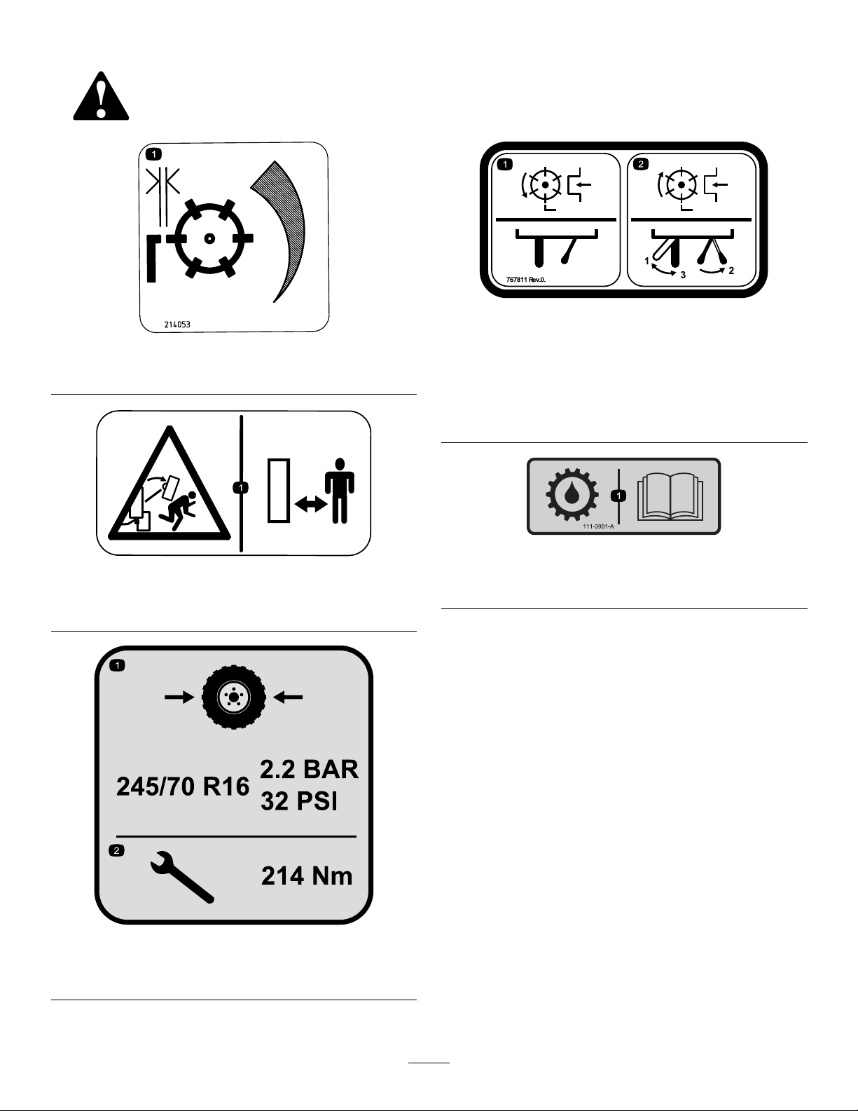
767811
214053
1.On-cutadjustment
749804
1.Crushing/fallinghazard—keepbystandersawayfromthe
machine.
1.Normalpositionofrotary
valvecontrolsforforward
cuttingunitrotation.
2.T oengage
backlap—rotatethelock
leverCWtoposition1;
rotatetherotaryvalve
CCWtoposition2;release
thelockleverCCWto
position3.
111-3901
1.Transmissionoil—readtheOperator'sManualformore
information.
1.Tirepressure—2.2bar(32
psi)
767810
2.T orquethenuts—214N-m
5
Page 6
61–13–019
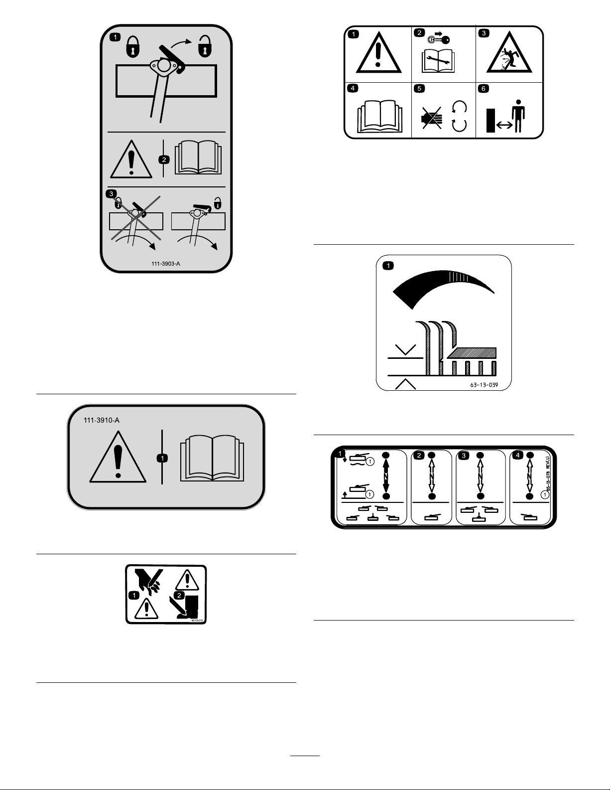
Model02701Only
1.Movethelevertotheleft
tolock—movetheleverto
therighttounlock.
2.Warning—readthe
Operator'sManual.
111-3903
3.Donotlowertheliftarm
whenthecuttingunitis
latchedinposition—unlock
thelatchbeforelowering
thecuttingunit.
1.Warning
2.Removethekeyfromthe
ignitionbeforeperforming
maintenance.
3.Thrownobjecthazard6.Keepbystandersaway
4.ReadtheOperator’s
Manual.
5.Keepawayfrommoving
parts.
frommachine.
63-13-039
1.Height-of-cutadjustment
111-3910
1.Warning—readtheOperator'sManual.
40-13–010
1.Cuttinghazardofhand
2.Cuttinghazardoffoot
1.Raise/lowerallthecutting
units.
2.Raise/lowertheleftcutting
unit.
6
65-13-078
Model02700
3.Raise/lowerthecenter
cuttingunits.
4.Raise/lowertheright
cuttingunit.
Page 7
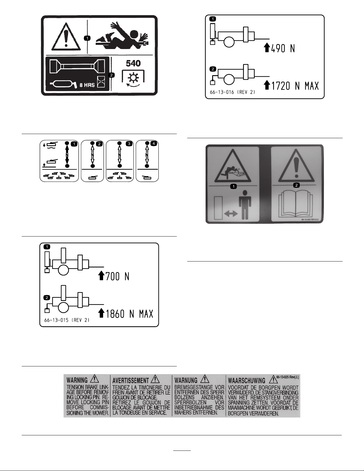
65–13–079
1.Warning—entanglement
hazard
2.LubricatethePTOshaft
every8hours—PTO540
rpm
1.Minimumdrawbar
load—490N
66-13-016
Model02700
2.Maximumdrawbar
load—1720Nmax
66–13–013
Model02701
1.Raise/lowerallthecutting
units.
2.Raise/lowertheleftcutting
unit.
1.Minimumdrawbar
load—700N
3.Raise/lowerthecenter
cuttingunits.
4.Raise/lowertheright
cuttingunit.
1.Hazard—spring-loaded
parkingbrake;keep
bystandersaway.
66–13–023
2.Warning—readthe
Operator’sManual.
66-13-015
Model02701
2.Maximumdrawbar
load—1860Nmax
66–13–025
7
Page 8

70-13-072
1.Jackingpoint
70-13-077
1.Warning—stoptheengineandremovetheignitionkey
beforereleasingoroperatingsafetylatches.
8
Page 9
Setup
LooseParts
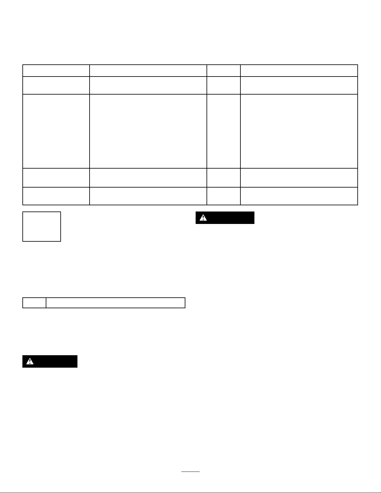
Usethechartbelowtoverifythatallpartshavebeenshipped.
ProcedureDescription
1
2
3
4
Cuttingunit(soldseparately)
Lightboard1
Light-boardbracket2
Bolt(M8x80)
Washer(M8)
Locknut(M8)
Light-boardsecuringplate2
Bolt(M10x40)
Washer(M10)
Locknut(M10)
Nopartsrequired
Nopartsrequired
1
InstallingtheCuttingUnits
Qty.
–
4
8
4
4
8
4
–
–
Installthecuttingunits.
Installthelights.
ChecktheminimumPTOlength
(maximumcompressedcondition).
CheckthemaximumPTOlength.
Use
WARNING
Thecuttingunitisheavyandcancausepersonal
injury.
Usesuitableliftingequipmentwhenremovingthe
cuttingunitfromthecartonandduringinstallation.
Model02700(TM5490)Only
Partsneededforthisprocedure:
–
Cuttingunit(soldseparately)
InstallingtheCuttingUnits
Model02700(TM5490)Only
CAUTION
Somecomponentsonthecuttingunitaresharpand
cancutyou.
Takecaretoavoidthesharpedgesofthecutting
cylinderandthebottombladewhenliftingor
workingonthecuttingunit.
1.Startthetractorengine,hitchupthemower,and
connectthePTOshaft.
2.Operatethecontrollevertoliftthesuspensionarms
tothefullyraisedpositiontoreducepressureonthe
arms;refertoControlLevers(page19).
3.Unlockthecutting-unitsuspensionarmsbymoving
theredtransportlatchestothereleasedpositionand
carefullylowerthearmstotheoor;refertoTransport
Latches(page19).
4.Unpackthe5cuttingunits.
5.Layoutthecuttingunitsaroundthemachineinthe
correctpositionsasshowninFigure2.
9
Page 10
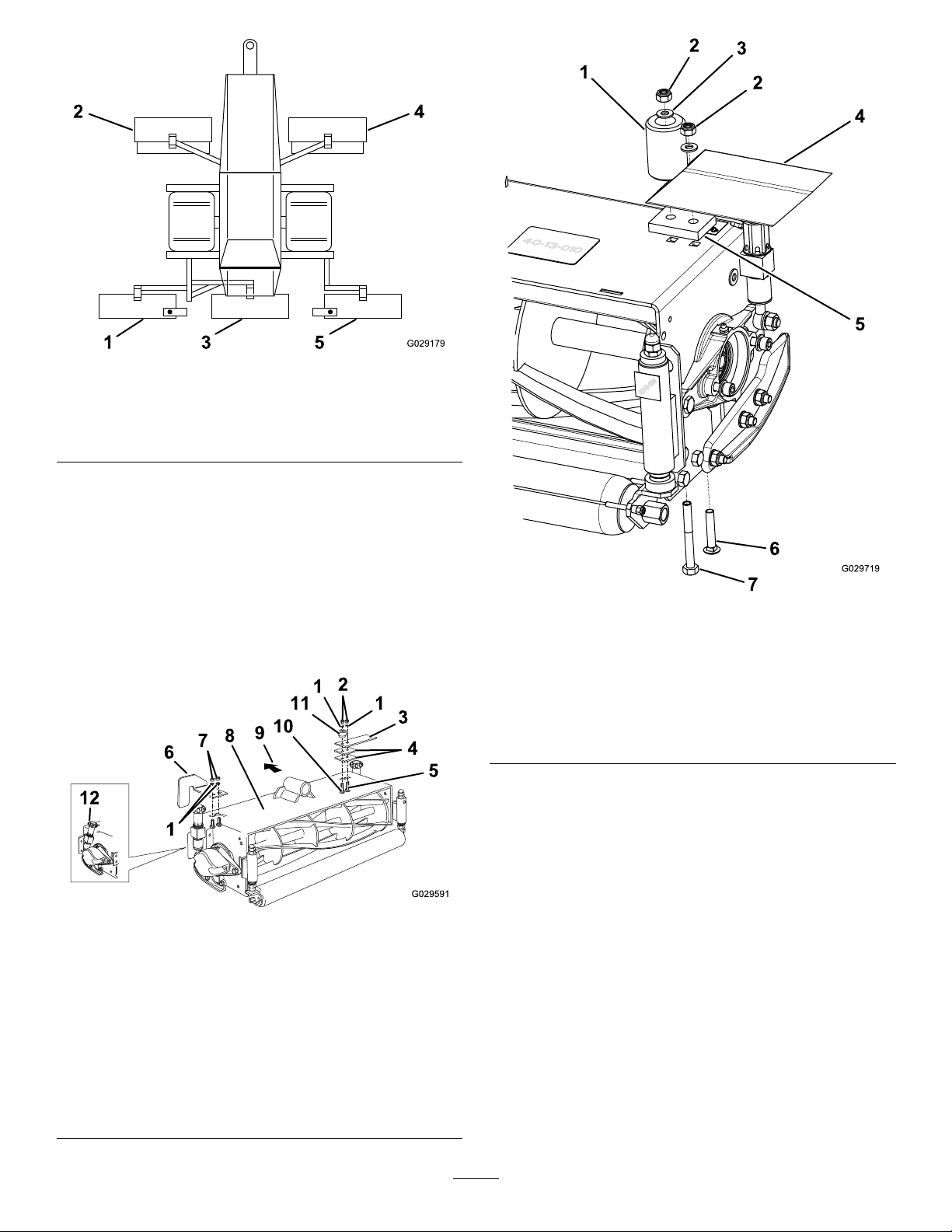
Figure2
1.Cuttingunit14.Cuttingunit4
2.Cuttingunit25.Cuttingunit5
3.Cuttingunit3
6.For254mm(10inch)cuttingunits,tthebumpstop,
2roller-boxplates,andtherollerplatetocuttingunits1
and5(hydraulic-motorend)using1carriagebolt(M10
x55mm),1hex-headbolt(M10x90mm),2locknuts
(M10),and2washers(M10);refertoFigure3.
For200mm(8inch)cuttingunits,tthebumpstop,
1roller-boxplate,andtherollerboxtocuttingunits1
and5(hydraulic-motorend)using1carriagebolt(M10
x55mm),1hex-headbolt(M10x90mm),2locknuts
(M10),and2washers(M10);refertoFigure4.
Figure4
200mm(8inch)cuttingunitonly
1.Bumpstop5.Roller-boxplate
2.Locknut(M10)6.Carriagebolt(M10x55
mm)
3.Washer(M10)7.Bolt(M10x90mm)
4.Rollerbox
7.Modifycuttingunits4and5fromleft-handto
right-handcongurationasfollows:
Figure3
Cuttingunits1and5only
1.Washer(M10)7.Locknut(M5)
2.Locknut(M10)8.Cutting-unitassembly
3.Plate9.Forward
4.Roller-boxplate
5.Carriagebolt(M10x55
mm)
6.Rightdeectorplate
10.Bolt(M10x90mm)
11.Bumpstop
12.Handwheelinangled-back
position
A.Removeanddiscardtheprotectivecover.
B.Removethesnapring.
C.Removethecounterweighttogetherwiththe
O-ringandtittothenon-driveend.
D.Tightenthesocket-headcapscrewsto80N-m
(59ft-lb).
10
Page 11

Figure5
Cuttingunits2and4only
1.Carriagebolt(M10x25
mm)
2.Washer(M10)9.Rightdeectorbracket
3.Locknut(M10)10.Carriagebolt(M10x55
4.Screw(M5x16mm)11.Leftdeectorbracket
5.Reardelfector12.Cutting-unitassembly
6.Deectorspacer
7.Washer(3/16inch)
8.Locknut(M5)
mm)
13.Forward
Important:Fitthesnapringtothedriveend.
8.Modifythecylinder-adjustmenthandwheelassemblies
oncuttingunit3totheangled-backpositionasfollows
(Figure6):
A.Removethenuts,bolts,andwashersfromthe
forwardholes.
B.Removethenuts,bolts,andwasherswhichattach
thehandwheelassembliestothecutting-unit
frame.
C.Removetheringboltclampnuts,washers,and
springwashers,andremovethehandwheel
assemblies.
Figure6
1.Handwheelangledtorear
9.Secureeachcuttingunittothemowerinthecorrect
positionusingthepivotpin,2locknuts(M24),2
washers(M24),2nutcaps,apinretainer,2Belleville
washers(whereapplicable),asetscrew(M12x30mm),
andaspringwasher(Figure7).
Note:Cuttingunits2and4mountinfrontoftheir
respectivesuspensionarms.
D.Adjustthehandwheelassembliestoprovidethe
correctfasteningcentersandinstalltheminthe
alternativepositions.
E.Installallfastenersandtightenthemsecurely.
Figure7
254-mmcuttingunit
1.Nutcap
2.Locknut(M24)7.Cutting-unitassembly
3.Screw(M12x30mm)
4.Springwasher(M12)
5.Suppliedwiththecutting
unit
11
6.Washer(M24)
8.Forward
9.Bellevillewashers
10.Pinretainer
Page 12
InstallingtheCuttingUnits
Model02701(TM7490)Only
CAUTION
Somecomponentsonthecuttingunitaresharpand
cancutyou.
Takecaretoavoidthesharpedgesofthecutting
cylinderandthebottombladewhenliftingor
workingonthecuttingunit.
WARNING
Thecuttingunitisheavyandcancausepersonal
injury.
Usesuitableliftingequipmentwhenremovingthe
cuttingunitfromthecartonandduringinstallation.
1.Startthetractorengine,hitchupthemower,and
connectthePTOshaft.
2.Operatethecontrollevertoliftthesuspensionarms
tothefullyraisedpositiontoreducepressureonthe
arms;refertoControlLevers(page19).
3.Unlockthecutting-unitsuspensionarmsbymoving
theredtransportlatchestothereleasedpositionand
carefullylowerthearmstotheoor;refertoTransport
Latches(page19).
4.Unpackthe7cuttingunits.
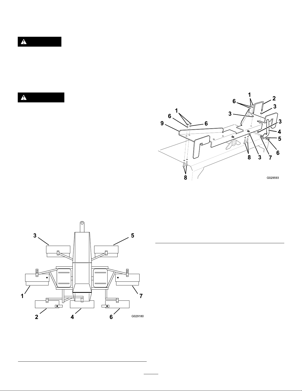
5.Layoutthecuttingunitsaroundthemachineinthe
correctpositionsasshowninFigure8.
6.Assemblethewing-armlatchplatesforcuttingunits1
and7asfollows(Figure9):
A.Fitthewasher(M16),thelatch,thespringwasher
(M12),andthelocknut(M12)totheshouldered
pinonthelatchplate.
B.Tightenthenutsothatthelatchisstiffbutcan
movefromsidetoside.
C.Assemblethehoseguideand4nuts(M10)tothe
latchplate.
D.Preparetheotherassemblyintheoppositehand
conguration.
Figure9
Cuttingunits1and7only
1.Locknut(M10)6.Locknut(M12)
2.Hoseguide
3.Nut(M10)8.Carriagebolt(M10x25
4.Latch9.Latchplate
5.Springwasher(M12)
7.Washer(M16)
mm)
Figure8
1.Cuttingunit15.Cuttingunit5
2.Cuttingunit26.Cuttingunit6
3.Cuttingunit37.Cuttingunit7
4.Cuttingunit4
7.For254mm(10inch)cuttingunits,tthebumpstop,
2roller-boxplates,andtherollerplatetocuttingunits2
and6(hydraulic-motorend)using1carriagebolt(M10
x55mm),1hex-headbolt(M10x90mm),2locknuts
(M10),and2washers(M10);refertoFigure10.
For200mm(8inch)cuttingunits,tthebumpstop,
1roller-boxplate,andtherollerboxtocuttingunits2
and6(hydraulic-motorend)using1carriagebolt(M10
x55mm),1hex-headbolt(M10x90mm),2locknuts
(M10),and2washers(M10);refertoFigure11.
12
Page 13

Figure10
Cuttingunits2and6only
1.Washer(M10)7.Locknut(M5)
2.Locknut(M10)8.Cutting-unitassembly
3.Plate9.Forward
4.Roller-boxplate
5.Carriagebolt(M10x55
mm)
6.Rightdeectorplate
10.Bolt(M10x90mm)
11.Bumpstop
12.Handwheelinangled-back
position
Figure11
200mm(8inch)cuttingunitonly
1.Bumpstop5.Rollerboxplate
2.Locknut(M10)6.Carriagebolt(M10x55
mm)
3.Washer(M10)7.Bolt(M10x90mm)
4.Rollerbox
8.Installthewing-armlatch-plateassemblies(step6)to
therespectivecuttingunits,andsecureeachassembly
with4carriagebolts(M10x25),4washers(M10),and
4locknuts(M10).
9.Modifycuttingunits5,6,and7fromleft-handto
right-handcongurationasfollows:
A.Removeanddiscardtheprotectivecover.
B.Removethesnapring.
C.Removethecounterweighttogetherwiththe
O-ringandtittothenon-driveend.
D.Tightenthesocket-headcapscrewstoatorqueof
80N-m(59ft-lb).
E.Fitthesnapringtothedriveend.
Note:Refertothecuttingunitoperator’ smanualfor
moreinformation.
13
Page 14

10.Modifythecylinder-adjustmenthandwheelassemblies
oncuttingunit4totheangled-backpositionasfollows;
refertoFigure6:
Note:Thehosesforcuttingunits1and7must
passthroughthehoseguideontherespective
wing-armlatch-plateassembly.
A.Removethenuts,bolts,andwashersfromthe
forwardhole.
B.Removethenuts,bolts,andwasherswhichattach
thehandwheelassembliestothecutting-unit
frame.
C.Removetheringboltclampnuts,washers,
andspringwashersandremovethehandwheel
assemblies.
D.Adjustthehandwheelassembliestoprovidethe
correctfasteningcentersandinstalltheminthe
alternativepositions.
E.Installallfastenersandtightenthemsecurely.
11.Secureeachcuttingunittothemowerinthecorrect
positionusingthepivotpin,2locknuts(M24),2
washers(M24),2nutcaps,apinretainer,2Belleville
washers(whereapplicable),asetscrew(M12x30mm),
andaspringwasher(Figure12).
Note:Cuttingunits3and5mountinfrontoftheir
respectivesuspensionarms
D.Alignandmeshthemotor-shaftsplinewiththe
couplingonthecuttingcylinder.Ensurethatthe
motorisfullylocatedintothebearinghousing.If
necessary,gentlytapthemotorintopositionwith
asoftmallet,untilitissecureagainstthebearing
housing.
E.Securethemotorinpositionusingthefasteners
previouslyremovedandtorqueto80N-m(59
ft-lb).
F.RepeatstepsAtoEfortheremainingcutting
units.
13.Fitthedeectorstocuttingunits1,3,5,and7using
thedeectorbracketsandspacers,andsecurethem
withthefastenersasshowninFigure13.
Figure12
1.Nutcap
2.Locknut(M24)7.Cutting-unitassembly
3.Screw(M12x30mm)
4.Springwasher(M12)
5.Suppliedwiththecutting
unit
6.Washer(M24)
8.Forward
9.Bellevillewashers
10.Pinretainer
12.Assemblethehydraulic-motorassembliestothecutting
unitsasfollows:
A.Removethesocketcapscrews,springwashers,
plainwashers,andtheprotectivecover.
B.Removethehosetiesecuringthehydraulic-motor
assemblytothemachine.
C.Unfoldthehosesandensurethattheyareneatly
routedwhileofferingthemotoruptothecutting
unit.
Figure13
Cuttingunits1,3,5,and7only
1.Carriagebolt(M10x25
mm)
2.Washer(M10)9.Rightdeectorbracket
3.Locknut(M10)10.Carriagebolt(M10x55
4.Screw(M5x16mm)11.Leftdeectorbracket
5.Reardelfector12.Cutting-unitassembly
6.Deectorspacer
7.Washer(3/16inch)
8.Locknut(M5)
mm)
13.Forward
14.Immediatelyfollowinginstallation,llallbearing
housingsfullofgreaseviathegreasettings.
Note:Thisrequiresasignicantquantityofa
good-quality,medium-gradegrease.
14
Page 15

2
InstallingtheLights
Partsneededforthisprocedure:
1Lightboard
2Light-boardbracket
4
Bolt(M8x80)
8
Washer(M8)
4
Locknut(M8)
2Light-boardsecuringplate
4
Bolt(M10x40)
8
Washer(M10)
4
Locknut(M10)
Procedure
1.Assemblethelight-boardbracketstotherearofthe
machine,using4bolts(M8x80),8washers(M8),and
4locknuts(M8),aswellasthe2fastenersholdingthe
divertervalvesforthetworearcornercuttingunits
(cuttingunits1and5forModel02700;cuttingunits2
and6forModel02701)tosecurethelowerpartofthe
bracketasshown(Figure14).
WARNING
Amalfunctioningdivertervalvecouldlead
toanaccidentandcausepersonalinjuryor
propertydamage.
Ensurethatthecamfollowerisincontact
withthecamandthatthedivertervalveaction
isinfullworkingorderafterassemblingthe
diverter-valvefasteners.
Figure14
1.Rightlight-boardbracket
2.Lightingboard
3.Washer(M10)8.Locknut(M8)
4.Bolt(M10x60mm)9.Bolt(M8x80mm)
5.Lightingboardsecuring
plate
6.Leftlight-boardbracket
7.Washer(M8)
10.Nut(M10)
Figure15
1.Divertervalve3.Armcam
2.Camfollower
2.Fitthelightboardtothebracketsandsecureitusing
2light-boardsecuringplates,4bolts(M10x40),8
washers(M10),and4locknuts(M10);refertoFigure
14.
3
CheckingtheMinimumPTO Length
NoPartsRequired
Procedure
Eachtractorcanbedifferent.ChecktheminimumPTO
lengtheverytimethatyouconnectthemowertoadifferent
tractor.
15
Page 16

Important:RemovethePTOshaftbeforepositioning
thetractorandperformingthisprocedure.
DANGER
Operatingamachineonaslopesteeperthanthat
speciedbythemachinemanufacturercouldresult
inpossibleinjuryordeath.
•Followtheslopelimitsspeciedbythetractor
manufacturer.
•Donotusethemoweronslopesgreaterthan
15degreeswiththecuttingunitslowered,or
greaterthan10degreeswiththecuttingunits
raised.
Reducetheslopeangleasrequiredifthestability
angleofthetowingtractorislessthanthatof
themower.
1.Withthetractorcoupledtothemachineinastraight
lineandparkedinapositiontogivetheshortest
PTO-shaftlength(Figure16),applythehandbrakeof
thetractor,turntheignitionswitchtotheOFFposition,
andapplythemowerparkingbrake.
Figure16
1.LocationofPTOshaft(removed)
Figure17
1.PTOshaftatshortest
workinglength
2.40mm(1-9/16inches)
3.Cuttheguardhere.
5.Removetheshaftsfromthemachineandthetractor.
Note:Cutonlytheplasticguardateachcuttingline,
takingcarenottomarktheshaftinside.
Note:Retainthecut-offsectionsoftheguard.
6.Usingacut-offsectionoftheguardasatemplate,mark
acuttinglinefromtheendofeachshaft(Figure18).
Note:Thisensuresthatyouremovethesameamount
ofshaftandguard.
2.Separatethe2halvesofthePTOshaft.
3.Assemblethehalfwiththewideanglejointtothe
tractorandtheotherhalftothemower.
4.Alignthe2halvessidebysideandtransferamarkfrom
thebackoftheguardendoftheotherhalf.Fromthis
mark,measureback40mm(1-9/16inches)andmarka
cuttinglineonbothhalves.
Figure18
1.Cut-offsectionofguard3.PTOshaft
2.EndofPTOshaftaligned
withendofguardsection
7.Cuteachshaftatthemark,usingasuitablecutting
device,suchasahacksaworanabrasivecuttingwheel.
16
Page 17

CAUTION
Youcouldbeinjuredifyoudonotwearthe
appropriatepersonalprotectiveequipment
whilecuttingtheshafts.
Weareyeprotection,earprotection,andwork
gloves.
4
CheckingtheMaximumPTO Length
8.Removeanyburrsandroughedgesfromtheinside
andoutsideofeachshaft.
Important:Burrsandroughedgeswilldamage
theRilsancoatingontheshaftsandshortenthe
workinglifeoftheshaft.
9.Drilla25mm(1inch)holeontheinnerguardtube
through1wallonly,andremoveallburrs(Figure19).
Note:Thisisforfuturegreasingoftheshaft.
Figure19
1.25mm(1inch)hole
10.Greasethe2shaftsandassemblethemtogether.
Note:Ensurethatthehalvesslidesmoothlyand
uninterrupted.
11.InstallthePTOshafttothemachineandthetractor.
Important:DonotmodifythePTOshaftinany
otherway .
NoPartsRequired
Procedure
Eachtractorcanbedifferent.CheckthemaximumPTO
lengtheverytimethatyouconnectthemowertoadifferent
tractor.
Connectthemowertoatractor;refertoConnectingthe
MowertoaTractor(page22).
1.RemovethePTOshaft.
2.Positionthetractor/mowercombinationwiththe
tractorturningsharplyonasteepdownwardslopeand
themoweronlevelground(Figure20).
DANGER
Operatingamachineonaslopesteeperthan
thatspeciedbythemachinemanufacturer
couldresultinpossibleinjuryordeath.
•Followtheslopelimitsspeciedbythe
tractormanufacturer.
•Donotusethemoweronslopesgreater
than15degreeswiththecuttingunits
lowered,orgreaterthan10degreeswith
thecuttingunitsraised.
Reducetheslopeangleasrequiredifthe
stabilityangleofthetowingtractorisless
thanthatofthemower.
Figure20
1.PTOshaft
17
Page 18

3.Setthetractorparkingbrake,stoptheengine,remove
theignitionkey,applythemowerhandbrake,andchock
thereartractorwheels.
4.AssemblethePTOshaft,ensuringthatthelarge
wide-anglejointisconnectedtothetractorPTO(as
shownonthePTOguard).
Important:Ensurethatthereleaseclipsarefully
engaged.Inthisposition,theoverlapofthe2
shaftsmustbeatleast1/3ofthelengthofeach
half-shaft(Figure21).Iftheshaftextensiondoes
notachievethisminimumoverlap,thenserious
damagewillresult.
Thetelescopicshaftshouldoperatewithasmuch
engagementaspossibleundernormalworking
conditionsforoptimumworkinglife.Ifitisless
thantheminimum,contactyourAuthorizedToro
Distributor.
Figure21
1.1/32.2/3
18
Page 19

ProductOverview
Controls
Thestandardcontrolsincludedwiththemachinearelevers.
Ifyourmachinehastheoptionalelectricliftkit,refertothe
kitinstructionsforinformationaboutthosecontrols.
ControlLevers
Thecontrollevers(Figure22)raiseandlowerthecutting
units.Theshortleverontheleftraisesandlowersallthe
cuttingunitstogether.Thelongleftleverraisesandlowers
onlytheleft-mostcuttingunit.Thelongcenterleverraises
andlowersthecentercuttingunits.Thelongrightleverraises
andlowersonlytheright-mostcuttingunit.
Back-LapControls
Figure23
1.Locklever2.Back-laplever
LockLever
Rotatethelocklever(Figure23)clockwiseallowtheback-lap
levertomove.Rotateitcounterclockwisetolocktheback-lap
leverintoposition.
1.Allcuttingunits
2.Leftcuttingunit
Back-LapLever
Rotatetheback-laplever(Figure23)counterclockwisetostart
backlappingthecuttingunits.
TransportLatches
Thetransportlatches(Figure24,Figure25,andFigure26)
automaticallysecurethecuttingunitsintopositionwhenyou
raisetheliftarms.Usethesafetylocktopreventthelatch
frombouncingupandreleasingthearm.
Note:Ifasafetylockisintheengagedpositionwhilethe
cuttingunitsareintheloweredposition,itpreventsthe
transportlatchfromlatchingautomaticallywhenyouraisethe
liftarms.Thereisnosafetylockonthewing-headlatches
(Model02701only).
Figure22
3.Centercuttingunits
4.Rightcuttingunit
Figure24
1.Transport
latch—automaticlatching
position
19
2.Safetylock—ippedup
Page 20

Specications
Model02700Model02701
Overallworking
width
Mowingwidth
Transportwidth
Overalllength360.0cm(141.7
Figure25
Transportheight
1.Safetylock—engaged
Approximate
workingweight
Drawbarweight
(transport)
PTOGearbox
368.0cm(144.9
inches)
350.0cm(137.8
inches)
212.0cm(83.5
inches)
inches)
161.0cm(63.4
inches)
1385kg(3053lb)1680kg(3703lb)
50kg(110.2lb)55kg(121.3lb)
497.0cm(195.7
inches)
478.0cm(188.2
inches)
237.0cm(93.3
inches)
360.0cm(141.7
inches)
160.0cm(63.0
inches)
Input
Output
Capacity1.0L(1.06USqt)
540rpm,1-3/8inch6-spline
PTOshaft,counterclockwise
rotation(lookingonendof
shaft)
1862rpmatpumpcoupling
Figure26
1.Wing-headlatch(Model02701only)
Attachments/Accessories
AselectionofToroapprovedattachmentsandaccessoriesisavailableforusewiththemachinetoenhanceandexpandits
capabilities.ContactyourAuthorizedServiceDealerorDistributor.
TobestprotectyourinvestmentandmaintainoptimalperformanceofyourToroequipment,countonTorogenuineparts.
Whenitcomestoreliability,Torodeliversreplacementpartsdesignedtotheexactengineeringspecicationofourequipment.
Forpeaceofmind,insistonT orogenuineparts.
20
Page 21

Operation
Note:Determinetheleftandrightsidesofthemachine
fromthenormaloperatingposition.
CheckingtheTirePressure
ServiceInterval:Beforeeachuseordaily
Tirepressure:221kPa(32psi)
CheckingtheHydraulicFluid
ServiceInterval:Beforeeachuseordaily
Tankcapacity:133L(35.1USgallons)
Totalsystemcapacity:142L(37.5USgallons)
Ambienttemperaturerange
0°to30°C(32°to86°F)ISOviscositygrade46
hydraulicuid
15°to40°C(59°to104°F)ISOviscositygrade68
hydraulicuid
CheckingthePump-Gearbox Oil
Capacity:1.0L(1.06USqt)
EP90gearoil
1.Checkthattheoilisuptotheleveloftheuppermark
onthedipstick(Figure27).
2.Topupwiththecorrectgradeofoilasnecessary
throughthedipstickhole.
Important:Donotoverllthegearbox.
1.Removethellercapontopofthehydraulictank.
2.Checkthelevelofthehydraulicuid.Ifitisnotatthe
upperblacklineontheuid-levelsightgaugelocatedat
thefrontofthetankunderthepumpcover,llittothe
correctlevelwiththecorrectgradeofhydraulicuid.
3.Installthellercapandwipecleananyspillage.
Figure27
1.Fillerplug/breather3.Drainplug(underside)
2.Dipstick
PreparingtheTractor
TheTM5490andTM7490trailedgangmowersaredesigned
forusewithstandardagriculturalorindustrialtractors
havingaminimumpowerof45bhp(TM5490)and70bhp
(TM7490).Theymustalsobeequippedwitharinghitch
(pintlehook)anda540rpmrearPTO .
TheTM5490andTM7490gangmowershaveafully
independenthydraulicsystemwhichispoweredfromthe
tractorrearPTO.Thesystemislivewhenyouengagethe
tractorrearPTO.Y oucanraiseorlowerthecuttingunitsvia
aremotecontrolsitedadjacenttotheoperator.
21
Page 22

DANGER
ModifyingasafetycaboraROPScanweakenit
andincreasethechancesofseriousinjuryordeath
intheeventofacrash.
Donotattachthemountingbracketstotheframe
orstructureofasafetycaboraROPS.
Dothisprocedureafterattachingthemowertothetractor
forthersttime.
Aquick-releasemountingbracketissuppliedwiththe
machineformountingthecontrolleverstothetractor,in
aconvenientpositionfortheoperator.Whenchoosinga
positionleaveadequateslackintheBowdencablestoallow
forarticulationofthetractorandmowerwhenturningor
negotiatingbrowsofhills,etc.Seriousdamagecouldresult
iftheBowdencablesbecomestretchedorpinchedinwork.
ChecktheroutingoftheBowdencablesandensurethatthey
arefreeofpinchpointsandhaveadequateslack.
Thetractorshouldbeequippedwithturf-patterntiresto
minimizedamagetoneturfareas.Consultyourtractor
operator’smanualortractordealerforfulldetailsof
recommendedtireequipment.Payparticularattentionto
thetractortirepressuresasthishasaconsiderableeffecton
steering,traction,andassociatedturfdamage.
ConnectingtheMowertoa Tractor
Important:Beforeusingthemower,ensurethatthe
PTOshaftistheappropriatelength;refertoSetup(page
9).
ConnectingtheHitches
1.Reversethetractortoapproximatelythecorrect
positioninrelationtothemowertoestablishthe
mowerdrawbarposition.
Figure28
1.T opsetofholesonmower
2.Middlesetofholeson
mower
3.Bottomsetofholeson
mower
4.Upperholesindrawbar
5.Lowerholesindrawbar
DrawbarMountingLocations
Upperholesin
drawbar
Topsetofholeson
mower
Middlesetofholes
onmower
Bottomsetofholes
onmower
546to570mm
(21.50to22.44
inches)
496to520mm
(19.53to20.47
inches)
0to470mm(0to
18.50inches)
4.Assemblethedrawbartothemowerintherequired
positionandtightenthe4fastenersto200N-m(148
ft-lb).
5.Lubricatethecontactpointsbetweenthemowerring
hitchandthetractorhitchwithgrease.
6.Connectthemowerringhitchtothetractorhitch.
Lowerholesin
drawbar
571to620mm
(22.48to24.41
inches)
521to545mm
(20.51to21.46
inches)
471to495mm
(18.54to19.49
inches)
2.Applythetractorparkingbrake,stoptheengine,and
removetheignitionkey.
3.Alignthemowertowhitchwiththetractorringhitch.
Ifnecessaryadjusttheheightoftheringhitchby
ttingthedrawbarintheappropriatemountingholes
inthemowerfrontplate;refertoDrawbarMounting
Locations(page22).
Figure29
1.Mowerfrontplate
2.Drawbar4.Tractorhitch
22
3.T owhitch
Page 23

7.Rotatethejockey-wheelhandleclockwisetoraisethe
jockeywheeltoapositionjustabovetheground.
Figure30
1.Handle
8.Unclampthejockey-wheelassembly,moveitupward
tothehighestposition,andclampitagaintosecure
itinthestorageposition.
9.Checkthatthemowerframeisstillhorizontallyaligned
withthegroundandadjustitifnecessary.
10.Assemblethebreakawaycablebetweenthehandbrake
leverandarigidlocationonthetractor.
Note:Ensurethatthebreakawaycablelocation
providesstraight-lineoperationintheeventofa
breakaway.
2.Clamplever
Figure31
1.Breakawaycable
11.Releasethehandbrakebycarefullymovingittothe
lowestposition.
12.AssemblethePTOshaft.
WARNING
AlwaysexaminetheconditionofthePTO
shaftandguardsbeforeuse.Neverusea
damagedPTOshaftassembly.
Important:EnsurethatthePTO-shaftrestis
foldeddowninthestoragepositionwhenthePTO
shaftisconnectedtothetractor.
13.GreasethePTOshaftbypartiallywithdrawingthe
telescopingshafttoexposethegreasenipplethrough
theouterguardapertureandlubricatingitwitha
good-qualitygrease.
14.Pushthetelescopingsectionbackintoposition.
15.Greasetheuniversaljoints.
16.Assemblethelargewideanglejointtothetractor(as
shownonthePTOguard)andtheotherendtothe
mower,ensuringthatthereleaseclipsarefullyengaged.
17.WhenthePTOiscorrectlyinstalled,attachthePTO
shaft-guardrestraintchains:connect1chaintothe
holeonthemowerPTOguardandconnecttheother
chaintoasuitablepositiononthetractor.
Important:Ifthetractorisequippedwitha3-point
linkage,checktherelationshipwiththemowerfor
potentialinterferencewhenmakingtightturnsorwhen
mowingundulatingground.Toeliminatepotential
damage,removethelowerlinkarmswhenusingthe
mower.
Note:Intheeventofthemoweruncouplingfrom
thetractorthebreakawaycableautomaticallyapplies
thebrakes.
WARNING
Usingadamagedbreakawaycablecould
resultinpersonalinjuryorpropertydamage.
Ensurethatthebreakawaycableisingood
workingcondition.
PositioningtheControlLevers
Unhookthecontrol-leverassemblyfromthemower
mountingbracketandattachittothetractormounting
bracket,ensuringthattheremotecablesareclearlyroutedand
freetoallowarticulationofthetractorrelativetothemower.
ConnectingtheLights
Connectthelightingplugofthemowertothelightsocketon
thetractor,andensurethatalllightsoperatecorrectlybefore
23
Page 24

usingthemower.Ensurethatthecableisneatlyrouted
alongsidethecontrolcables.
ConnectingtheBrakeHose
Note:Donotallowtheremote-controlboxtolieon
theground.
7.Disconnectthelighting-systemplugandcablefromthe
tractorsocketandstoreitonthemower.
Connectthebrakehosefromthefrontbulkheadofthe
mowertothetractorauxiliarybrakeconnector.Checkthat
thebrakingsystemoperatescorrectlybeforeusingthemower.
Ensurethatthehoseisneatlyroutedalongsidethecontrol
cableandthelightingcable.
DisconnectingtheMowerfrom aTractor
WARNING
Improperlydisconnectingthemowerfromatractor
couldresultinseriousinjuryorpropertydamage.
Beforeattemptingtodisconnectthemowerfrom
thetractoralwaysdothefollowing:
•Positionthetractorandthemoweronlevel
ground.
•Applythetractorparkingbrake,disengagethe
PTOdrive,stoptheengine,removetheignition
key,andsetthemowerhandbrake.
1.Carefullyraisethehandbrakelevertothehighest
positiontoengagethemowerbrakes.
2.Disconnectthebreakawaycablefromthetractor.
3.Supportthemoweronthejockeywheelasfollows
(Figure30):
8.Operatethetractortodisconnecttheringhitchfrom
themowertowhitch.
9.Disconnectthebrakehosefromtheauxiliarybrake
connectoronthetractor.
10.Connectthebrakehosetothettingmountedonthe
mowerbulkhead.
11.Movethetractorawayfromthemower.
Important:Checkthattherearenoobstructions
andthatallconnectionstothemowerare
disconnectedbeforedrivingthetractorawayfrom
themower.
PreparingtheMowerfor Transport
1.StartthetractorengineandengagethePTOdrive.
2.Operatetheoverridecontrollever(shortcontrollever)
toliftallcuttingunitstothefullyraisedtransport
position.
3.Stopthetractorengine,returntothemower,and
secureallcutting-unitsuspensionarmsandouter
cuttingunitsinthetransportpositionbylockingthe
transport-latchsafetylocks.
4.Applyathincoatingofgreasetoallexposed
hydraulic-cylinderrodsandtothefacesofthe
diverter-valveoperatingcams.
A.Releasetheclamplevertounclampthejockey
wheel.
B.Lowerthewheeltotheground,andclampthe
jockeyassemblyagain.
C.Turnthehandletocausethedrawbartoriseup
andoffthetractorhitch.
4.DisconnectthePTOshaftfromthetractorandstore
itonthePTO-shaftrest.
Note:NeverrestthePTOshaftontheground.
5.Disconnectthemanual-levercontrol:Removethe
control-leverassemblyfromthetractorandattachit
tothestoragepositiononthemowerwiththecables
neatlycoiledandprotectedfromdamage.
6.Ifthemowerisequippedwiththeoptionalelectriclift
kit,disconnectthepowercablefromthecigar-lighter
socketandthecontrolcablefromthein-cab
remote-controlunitasfollows:
Detachtheremote-controlboxfromitsmounting
bracketonthetractorandstowitonthemower.
OperatingtheMower
CheckingtheControls
Operatetheouterlongcontrolleversinturntoliftthe2wing
cuttingunits(cuttingunits1and5forModel02700,orcutting
units1and7forModel02701).Carryoutthisexercisewith
careandobservethemovementofthecuttingunitstoensure
thattheyarenotimpededbypoorroutingofthehydraulic
hoses.Itisnormaltoexperiencesomedelayintheresponse
ofthecontrolsforthersttimeasairispurgedfromthe
hydraulicsystem.Lowerthecuttingunitstotheground.
Operatethecenterlongcontrollevertoraisethecentral
cuttingunits(cuttingunits2,3,and4forModel02700,or
cuttingunits2,3,4,5,and6forModel02701),followingthe
sameprocedureoutlinedabove.
24
Page 25

CommissioningtheBrakingSystem
OperatingTips
WARNING
Ifyoutestthemachinewherethereareotherpeople
andvehicles,thereisariskofinjuryandproperty
damage.
Performthesetestsonaprivateroad,where
possible.
1.Inspectthebrakesystemandensurethatall
componentsareassembledandsecuredcorrectlyand
thatallcablesarecorrectlytensioned.Carefullyoperate
thehandbrakeupwards.Ensurebrakesareonwhen
theleverhasmoved70to80percentofitstravel.If
not,releasethehandbrake,adjustusingturnbuckleand
retry.
Note:Repeatthissequenceuntil70to80percenthas
beenachieved.
2.Applythehandbrakeagain.
3.Operatethetractorandattempttopullthemower
forwards.Checkthatthemowerbrakesoperate
satisfactorily.Operatethetractorandattempttopush
themowerinreverse.Checkthatthemowerbrakes
operatesatisfactorily.
•Therotationalspeedofthecuttingcylindersshould
alwaysbekeptashighaspossibleinordertomaintain
thehighestqualityofcut.Thisinturnrequiresthatthe
tractorenginespeedbekeptashighaspossiblewithout
exceedingaPTOspeedof540rpm.
•Excessiveforwardspeedcausesthequalityofcutto
deteriorate.Alwaysbalancethequalityofcutwiththe
workraterequiredandsettheforwardspeedaccordingly.
•Neverletthetractorenginelabor.Reducetheforward
speedorincreasetheheightofcut.Checkthatthecutting
cylindersarenotinheavycontactwiththeirbottom
blades.
•Regularlycheckthecylindertothebottomblade
adjustmenteveryfewhoursevenwhencutting
performanceappearstobesatisfactory.Heavycontact
orexcessiveclearancebetweenthecylindersandbottom
bladescausesrapidweartotakeplace.
•AlwaysdisengagethetractorPTOwhentravellingacross
areaswithnograss.Grasslubricatesthecuttingedges
whilemowing.Excessiveheatwillbuildupifyourunthe
cuttingcylinderswhennotmowing,andthiscausesrapid
weartotakeplace.Therefore,reducethecuttingcylinder
speedwhenmowinglightlygrassedareasorwhenthe
grassisdry.
Note:Ifcorrectoperationisnotachieved,checkthe
brakesystemlinkagesagain.Consultyourdealerif
assistanceisrequired.
4.Lowerthehandbrakelevertoitslowestpositionto
releasethebrakes.
5.Drivethetractor/mowercombinationinastraightline
at32km/h(20mph)andbrakegraduallyandrmly
withoutskidding.Checkthebrakingperformanceof
themower.
Note:Ifthebrakingeffectattheleftandrightwheels
isunequal,adjustthewheelbrakecables.Repeatthe
brakingtestuntilsatisfactoryperformanceisachieved.
6.Drivethetractor/mowercombinationatthemaximum
speedatwhichitistobeusedbutdonotexceed40
km/h(25mph);refertoSafeOperatingPractices(page
3).Applythebrakermlywithoutskidding.Before
comingtorest,increasethespeedbacktomaximum.
Note:Ensurethatthebrakingperformanceisgradual
andsympathetictothesystem(notsevere).Avoid
aggressive/violentbrakingduringthesetestsinorder
toallowthebrakepadstobed-incorrectly.
•Cuttingperformanceisbestwhencuttingagainstthelie
ofthegrass.Therefore,youshouldattempttoalternate
thedirectionofmowingbetweencuts.
•Donotleaveuncutstripsofgrassattheoverlappoints
betweentheadjacentcuttingunitsbyavoidingtightturns.
•Removetherearrollerscraperswhereconditionsallow ,
asbestgrassdischargeisachievedwithoutthem.Install
thescraperswhenconditionsaresuchthatmudandgrass
starttobuildupontherollers.
25
Page 26

Maintenance
Note:Determinetheleftandrightsidesofthemachinefromthenormaloperatingposition.
Note:Toobtainanelectricalschematicorahydraulicschematicforyourmachine,visitwww.Toro.com.
RecommendedMaintenanceSchedule(s)
MaintenanceService
Interval
Aftertherst50hours
Beforeeachuseordaily
Every50hours
Every250hours
Every500hours
DailyMaintenanceChecklist
Duplicatethispageforroutineuse.
MaintenanceProcedure
•Adjustthebrakes.
•Changethehydraulic-uidreturnlter.
•Checkthetirepressure.
•Checkthehydraulicuid.
•Checkthetirepressure.
•Greasethebearings,bushings,andpivots(greasethemimmediatelyafterevery
washingregardlessoftheintervallisted).
•LubricatethePTOshaft.
•Greasethebearings,bushings,andpivots(greasethemimmediatelyafterevery
washingregardlessoftheintervallisted).
•Lubricatethebrakelink.
•Inspectthebrakes.
•Replaceallbrakecables.
•Servicethehydraulicsystem.
•Changethehydraulic-uidreturnlter.
Fortheweekof:
MaintenanceCheckItem
Checkthesafetyinterlockoperation.
Checkthebrakeoperation.
Checkunusualoperatingnoises.
Checkthehydraulic-systemoillevel.
Checkhydraulichosesfordamage.
Checkforuidleaks.
Checkthetirepressure.
Checktheoperationofthecontrols.
Checkthecylinder-to-bedknifeadjustment.
Checktheheight-of-cutadjustment.
Checkallgreasettingsforlubrication.
Touchupdamagedpaint.
1.Checktheglowplugandinjectornozzlesifhardstarting,excesssmoke,orroughrunningisnoted.
2.Immediatelyaftereverywashing,regardlessoftheintervallisted
2
Mon.Tues.Wed.Thurs.Fri.
Sat.Sun.
26
Page 27

NotationforAreasofConcern
Inspectionperformedby:
ItemDate
1
2
3
4
5
Information
Lubrication
GreasingtheBearings, Bushings,andPivots
ServiceInterval:Beforeeachuseordaily
Every50hours
Lubricateallgreasettingsforthebearingsandbushingswith
general-purpose,lithium-basedgrease.Lubricatebearings
andbushingsimmediatelyaftereverywashing,regardlessof
theintervallisted.
Replaceanydamagedgreasettings.
Greaseallcutting-unit-greasepointsandinjectsufcient
greasesuchthatyoucanseecleangreaseescapingfromthe
rollerendcaps.Thisprovidesvisibleevidencethattheroller
sealshavebeenpurgedofgrass,ensuringmaximumworking
life.
Thegrease-ttinglocationsandquantitiesareasfollows:
Note:Ifyourmachineisequippedwiththeoverrundrawbar,
thedrawbarmayrequirelubricationaswell.
Figure32
Model02700
1.–Greasedaily3.–Greaseevery50hours(weekly)
2.
–Greasedaily(iftted)
27
Page 28

Figure33
Model02701
1.–Greasedaily3.–Greaseevery50hours(weekly)
2.
–Greasedaily(iftted)
LubricatingtheBrakeLink
ServiceInterval:Every250hours
Lubricatethebrakelinkwithoilandensurethatitoperates
freely.
LubricatingthePTOShaft
ServiceInterval:Beforeeachuseordaily
Exposethegreasettingontheshaftthroughtheouterguard
aperture,andinjectgreaseintothetting.
Lubricatetheuniversaljoints.
LubricatingtheCuttingUnits
RefertothecuttingunitOperator’sManualforadditional
informationaboutlubricatingthecuttingunits.
BrakeMaintenance
InspectingtheBrakes
ServiceInterval:Every250hours
Figure34
1.Brakeshoe
Removethewheelhubsandinspectthebrakeshoes(Figure
34).Replacetheshoesiftheliningthicknessislessthan1.5
28
2.Spring
Page 29

mm(0.059inch).UsegenuineT ororeplacementparts.Do
notrelinethebrakeshoes.
•Checkthatthebrakewedgesoperatethebrakeshoes
correctly.Wedgeswhicharewornexcessivelydonot
applythebrakesfully;replacethem.
•Ensurethatthebrakecablesoperatefreelyandthatthere
arenosignsoffrayingorotherdamage.Alwaysreplace
damagedcables.
•Ensurethatallbrakelinkagesareingoodcondition,
operatefreely ,andaresecuredcorrectly.Lubricateall
pivotpointswithoil.
Checkthebrakecylinderandtheassociatedhydraulichoses
forleaks.Alwaysreplaceanyleakingcomponents.
AdjustingtheBrakes
ServiceInterval:Aftertherst50hours
1.Raisethemachinesothatthewheelsareofftheground.
WARNING
ReplacingtheBrakeCables
ServiceInterval:Every500hours
ContactyourAuthorizedToroDistributor.
Mechanicalorhydraulicjacksmayfailto
supportthemachineandcauseseriousinjury.
Usejackstandswhensupportingthemachine.
2.Rotatetheleftwheelinthedirectionofforwardtravel.
3.Turnthebrakeadjuster(Figure35)untilthewheelis
nolongerabletorotate.
Note:Thisputspreloadonthebrakes.
Figure35
1.Brakeadjuster2.Backplate
4.Turnthebrakeadjusterbackinhalf-turn
increments—tappingtheadjusteraftereach
increment—untilyoucanrotatethewheelbyhand
againstslightresistance.
5.Repeattheprocedurefortheotherwheel.
6.Carefullylowerthemachinetotheground.
29
Page 30

HydraulicSystem
Maintenance
ChangingtheHydraulic-Fluid ReturnFilter
ServiceInterval:Aftertherst50hours
ServicingtheHydraulic System
ServiceInterval:Every500hours
WARNING
Hydraulicuidescapingunderpressurecan
penetrateskinandcauseinjury.
•Makesurethatallhydraulicuidhosesand
linesareingoodconditionandallhydraulic
connectionsandttingsaretightbefore
applyingpressuretothehydraulicsystem.
•Keepyourbodyandhandsawayfrompin-hole
leaksornozzlesthatejecthigh-pressure
hydraulicuid.
•Usecardboardorpapertondhydraulicleaks.
•Safelyrelieveallpressureinthehydraulicsystem
beforeperforminganyworkonthehydraulic
system.
Every500hours
1.Removethetopofthereturn-lterassembly.
Figure36
1.Filtercanister(Part65-06-483)
2.Withdrawthelter-elementcanisteranddiscardit.
3.Installanewltercanister(Part65-06-483)andinstall
thescrewtop.
Important:EnsurethattheO-ringsealis
correctlypositioned.
•Getimmediatemedicalhelpifuidisinjected
intoskin.
1.Lowerthecuttingunitstothegroundanddrainthe
hydraulicuidbyremovingthehydraulic-tankdrain
plug.
2.Removetheoil-tank-llerangetoaccessthestrainer
insidethetank.
3.Unscrewandremovethestrainer.
4.Cleanthestrainerinparafn(kerosene).
Note:Replacethestrainerifitisdamaged.
5.Installthestrainer.
Replacethereturn-lineoil-lterelement;refertoChanging
theHydraulic-FluidReturnFilter(page30).
30
Page 31

Cutting-UnitSystem
G014445
Maintenance
BackLappingtheCutting Units
Thisprocessisforrestoringthesharpcuttingedgestothe
cylindersandthebottomblades,whichareessentialfor
good-qualitygrasscutting.
Thisprocessremovesonlyasmallamountofmetaltorestore
thecuttingedges.Ifthebladeedgesareseverelywornor
damaged,removethecomponentpartsandhavethem
groundagain.
1.Lowerthecuttingunitstotheground.
2.Ensurethatthetractorengineisoffandthatthe
parkingbrakeisset.
3.Adjustthecuttingcylinderstothebottombladesto
obtaineetingcontact.
4.Applyamedium-grade,detergent-basedcarborundum
pastetothecuttingedgesofthecylinderswitha
long-handledbrush.
80-gradecarborundumpaste
WeightPartnumber
0.45kg(1lb)
11.25kg(25lb)
5.Sitontheoperatorseat,startthetractorengine,and
settheenginespeedatidle.
63-07-088
63-07-086
Figure37
WARNING
Ifyoutouchthecuttingunitswhentheengine
isrunning,youcouldbeseriouslyinjured.
•Ensurethattheareasurroundingthe
cuttingunitsisclearofpeople.
•Keephandsandfeetclearofthecutting
cylindersduringtheperiodwhenthe
tractorengineisrunning.
6.Settherotaryvalveattherearofthemachineto
REVERSE;refertoFigure38.
31
Page 32

Storage
•Parkthemoweronlevelground.
•Performroutinechecks.
•Releasethemowerbrakes—operatethemowerhandbrake
downwardtothelowestpositiontoreleasethemower
brakes.
Figure38
1.Normalpositionofrotary
valvecontrolsforforward
cutting-unitrotation
7.OperatethetractorPTOswitch/levertotheOFF
position(Figure38)andswitchoffthetractorengine
whenthegrindingactionhasstopped.
8.Thoroughlycleanthebladeedgesandadjustthecutting
cylinderstothebottomblades.
9.Checkthatathinpieceofpapercanbecutcleanlyat
allpointsalongthecuttingedgeswhilerotatingthe
cylindersbyhand.
10.Iffurtherbacklappingisnecessary,repeatsteps3
through9.
11.Thoroughlyremoveandwashoffalltracesofthe
carborundumpastefromthecylindersandthebottom
blades.
2.T ostarttheback-lapping
procedure,rotatethe
lockleverclockwiseto
position1;rotatetherotary
valvecounterclockwiseto
position2;releasethelock
levercounterclockwiseto
position3.
•Adjustthecuttingcylinderssuchthattheyareclearofthe
bottomblades.
•Preventtiredistortion—supportthemowerchassison
blockssuchthatthetiresareclearofthegroundto
preventtiredistortion.
•Preventcorrosion—treatbaremetalsurfacesincluding
thecuttingedgesofthecuttingcylinders,bottomblades,
andexposedhydraulic-cylinderrodswithgrease,oil,ora
proprietarycorrosioninhibitor.
12.Movethecontrollevertotheoriginalpositionfor
normaloperation.
Note:Theback-lapcontrollockshouldspringback,
lockingthecontrolleverinposition.
GrindingtheCuttingUnits
HaveyourToroAuthorizedDistributorcarryoutagrinding
operationtocorrectthecylinderspiraledgesand/or
bottom-bladeedgeswhentheyhavebecomeexcessively
roundedordistorted.Ifthebottombladesarenearingthe
endoftheirwearlife,havethemreplaced.Havethenew
bladesgroundontheirholderspriortoinstallingthem.Grind
boththecylindersandthebottombladesatthesametime.
Theonlyexceptiontothisruleiswhenanewcylinderistted,
inwhichcaseitisonlynecessarytogrindthebottomblade.
Allsuchgrindingoperationsshouldbecarriedoutbyyour
authorizeddealerordistributoronaquality,well-maintained
cylinder/bottom-bladegrindingmachine.
32
Page 33

Troubleshooting
Problem
Thereareareasofuncutgrassatthe
overlapbetweencuttingcylinders.
Therearefull-widthridgelinesinthecut
acrossthedirectionoftravel.
Thereareridgelinesinthecutgrass,
acrossthedirectionoftravel,overthe
cuttingwidthof1cylinder.
Thereisastepinthecutgrassheight
atthepointofoverlapbetweencutting
cylinders.
PossibleCauseCorrectiveAction
1.Y ouareturningtootightly.1.Increasetheturningradius
2.Themachineslidessidewayswhen
travellingacrossthefaceofaslope.
3.Thereisnogroundcontacton1end
ofthecutterbecauseofpoorlyrouted
hosesorwronglypositionedhydraulic
adaptors.
4.Thereisnogroundcontacton1end
ofthecutterbecauseapivotpinis
seizing.
5.Thereisnogroundcontacton1end
ofthecutterbecauseofgrassbuildup
underthecutterhead.
1.Theforwardspeedistoohigh.1.Reduceforwardspeed.
2.Thecylinderspeedistooslow.2.Increasethetractorenginespeed.
3.Theheightofcutistoolow.3.Raisetheheightofcut.
1.Acylinderisrunningslow.
1.Thereisaninconsistentheightofcut
settingon1cylinder.
2.Theraise/lowerpositioncontrolisnot
intheoatposition.
3.Thereisnogroundcontacton1end
ofthecutterbecauseofpoorlyrouted
hosesorwronglypositionedhydraulic
adaptors.
4.Thereisnogroundcontacton1end
ofthecutterbecauseofpivotpins
seizing.
5.Thereisnogroundcontacton1end
ofthecutterbecauseofgrassbuildup
underthecutterhead
2.Mowup/downtheslope.
3.Correctthehoseroutingortheposition
ofthehydraulicadaptors.
4.Releaseandgreasethepivotpoints.
5.Clearthegrassbuildup.
1.Checkthecylinderspeed;consultyour
authorizeddistributor.
1.Checkandadjusttheheightofcut
setting.
2.Setthepositioncontroltotheoat
position.
3.Correctthehoseroutingandthe
positionofthehydraulicadaptors.
4.Releaseandgreasethepivotpoints.
5.Removethegrassbuildup.
Therearesomeuncutorpoorlycut
strandsofgrass.
Therearelinesofuncutorbadlycutgrass
inthedirectionoftravel.
1.Acuttingcylinderispartiallyoutof
contactwiththebottomblade.
2.Acuttingcylinderisinheavycontact
withthebottomblade.
3.Theheightofcutistoohigh.3.Lowertheheightofcut.
4.Thecuttingedgesofthecutting
cylinders/bottombladesarerounded.
1.Thereistramliningofthecutting
edgesduetoheavycontactcausedby
poorcutting-cylinder-to-bottom-blade
adjustment.
2.Thebottombladeisincontactwiththe
ground.
3.Thebottombladehasanose-down
attitude.
4.Thecutterheadsarebouncing.
5.Thereareworncylinder
bearings/bearinghousingpivots.
6.Thereareloosecomponentsinthe
cutterhead.
1.Adjustthecontactbetweenthecutting
cylinderandthebottomblade.
2.Adjustthecontactbetweenthecutting
cylinderandthebottomblade.
4.Backlaporgrindtheedges.
1.Backlaporgrindtheedges.
2.Raisetheheightofcut.
3.Adjustthecutterheadtopositionthe
bottombladeparalleltotheground.
4.Reducetheforwardspeedandreduce
theweighttransfer.
5.Replaceanywornparts.
6.Checkandtightencomponentsas
necessary.
33
Page 34

Problem
PossibleCauseCorrectiveAction
Thereisexcessivebottombladewear .
Thehydraulicsystemoverheats.
1.Theundulationsaretoosevereforthe
1.Useoatingcutterheads. Thereisscalpingoftheturf.
heightofcutsetting.
2.Theheightofcutistoolow.2.Raisetheheightofcut.
1.Thebottombladeisinheavycontact
1.Raisetheheightofcut.
withtheground.
2.Thecuttingedgesofthecutting
2.Backlaporgrindtheedges.
cylinderand/orbottombladeare
rounded.
3.Thecylinderisinheavycontactwith
thebottomblade.
4.Thereisadamagedcuttingcylinderor
3.Adjustthecontactbetweenthecutting
cylinderandthebottomblade.
4.Grindorreplacepartsasnecessary.
bottomblade.
5.Thereareexcessivelyabrasiveground
5.Raisetheheightofcut.
conditions.
1.Thecylindersaretightagainstthe
1.Adjustthesettings.
bottomblades.
2.Thereliefvalvesettingislow.2.Havethereliefvalvepressurechecked.
Consultyourauthorizeddistributor.
3.Thebrakesareapplied.3.Releasethebrakes.
4.Theuidlevelislow.
4.Fillthereservoirtothecorrectlevel.
5.Theworkrateistooexcessive.5.Reducetheworkratebyincreasing
theheightofcutand/ordecreasingthe
forwardspeed.
6.Thehydraulicuidisthewrong
viscosity.
6.Drainthehydraulicsystemandll
itwithuidofthecorrectgradeand
viscosity.
Thereisexcessivenoiseinthehydraulic
system.
Thecylindersrotateinthewrongdirection.
1.Apumpiswornordamaged.
1.Identifythenoisypumpandserviceit
orreplaceit.
2.Amotoriswornordamaged.
2.Identifythenoisymotorandserviceit
orreplaceit.
3.Thereisairleakingintothesystem.3.Tightenorreplacetheleakinghydraulic
ttings,particularlyinthesuctionlines.
4.Thesuctionstrainerisblockedor
4.Cleanorreplacethesuctionstrainer.
damaged.
5.Theuidviscosityisincreaseddueto
5.Allowthesystemtowarmup.
coldconditions.
6.Therelief-valvesettingislow.6.Havetherelief-valvepressure
checked.Consultyourauthorized
distributor.
7.Thehydraulic-uidlevelislow.
1.Theback-lapcontrolleverisnotlocked
intheNORMALOPERATIONposition.
2.Thehosesareconnectedwrongly.
7.Fillthereservoirtothecorrectlevel.
1.Locktheback-lapcontrolleverinthe
NORMALOPERATIONposition.
2.Checkthehydrauliccircuitandconnect
thehosescorrectly .
34
Page 35

Problem
PossibleCauseCorrectiveAction
Afteraninitialperiodofsatisfactory
operation,themachinelosespower .
Acylinderknockswhilerotating.
Onecylinderrotatesslowly.
1.Apumpormotorisworn.1.Replacepartsasnecessary.
2.Thehydraulic-uidlevelislow.2.Fillhydraulicuidtanktocorrectlevel
3.Theuidinthehydraulicsystemhas
thewrongviscosity .
3.Replacetheoilinthehydraulictank
withthecorrectviscosity-gradeoil;
refertotheSpecicationssection.
4.Thelterelementisblocked.4.Changethelterelement.
5.Thepressurereliefvalveis
malfunctioning.
5.Havethereliefvalvecleanedand
thepressurechecked.Consultyour
authorizeddistributor.
6.Thesystemisoverheating.
6.Checkthecylinder-to-bottom-blade
adjustment.Reducetheworkrate
(increasetheheightofcutorreduce
theforwardspeed).
7.Thereareleaksonthesuctionhose.
7.Checkandtightenthettings.Replace
thehoseifnecessary.
1.Thereisahighspotonthecylinderor
thebottombladeduetocontactwitha
foreignobject.
1.Removethehighspotwithastoneand
backlaptorestorethecuttingedges.
Severedamagewillrequiregrinding.
2.Thecylinderbearingsareworn.2.Replacethebearingsasnecessary.
1.Acuttingcylinderbearingisseized.1.Replacethebearingsasnecessary.
2.Amotorwithincorrectrotationwas
installed.
3.Themotorintegralcheckvalveis
jammedopen.
4.Thecuttingcylinderistightonthe
2.Checkthemotorandreplaceitif
necessary.
3.Havethecheckvalvecleanedand
checked.
4.Adjustthesetting.
bottomblade.
5.Themotorisworn.5.Replacethemotor.
Acuttingunitfailstoliftoutofwork.
Thecuttingunitsdonotfollowthecontours
oftheground.
1.Thereisalift-cylindersealfailure.
2.Thepressurereliefvalveisjammed
openorwronglyset.
1.Replacetheseals.
2.Havethereliefvalvepressurechecked.
Consultyourauthorizeddistributor.
3.Thereisamalfunctioningcontrolvalve.3.Overhaulthecontrolvalve.
4.Thereismechanicalblockage.4.Removetheblockage.
1.Thehoseroutingortheorientationof
thehydraulicttingsisincorrect.
1.Movethecuttingunitsthroughoutthe
extremesofmovementandobserve
anytightnessinthehoses.Correctly
routethehosesandorientatethe
ttingsasnecessary .
2.Thepivotpointsaretootight.2.Releaseandgreasethepivotpointas
necessary.
3.Themowerisbeingoperatedinthe
HOLDposition.
3.Movethepositioncontrolswitchtothe
DOWN/FLOATposition.
4.Theweighttransferissettoohigh.4.Reducetheweighttransfer.
35
Page 36

Problem
PossibleCauseCorrectiveAction
Thecuttingunitsfailtostartupwhen
loweredintowork.
ThePTOshaftisheavilyworn.
1.Theseatsensorswitchis
malfunctioning.
1.Checkthemechanicalandelectrical
operationoftheswitch.
2.Thehydraulic-uidlevelislow.2.Fillthehydraulic-uidreservoirtothe
correctlevel.
3.Adriveshaftissheared.3.Checkthemotorandcylinder
driveshaftsandreplacethemif
necessary.
4.Thepressurereliefvalveisjammed
openorwronglyset.
4.Havetherelief-valvepressure
checked.Consultyourauthorized
dealer.
5.Acuttingcylinderisjammed.
6.Acuttingcylinderistightonthebottom
5.Clearanyjamsasnecessary.
6.Adjustthesetting.
blade.
7.Acutting-unitcontrolvalveisinthe
OFFposition,causedbymalfunctioning
7.Overhaulthecontrolvalve.
controlvalve.
8.Acutting-unitcontrolvalveisintheOFF
position,causedbyanelectricalfault.
9.Thelift-armproximityswitchis
8.Havetheelectricalsystemcheckedfor
anelectricalfault.
9.Checkandadjusttheproximityswitch.
incorrectlyset.
1.Thereisalackoflubrication.1.GreasethePTOshaftevery8hours.
2.Thereisinsufcientoverlaptheinner
sectionandtheoutersectionofthe
2.CheckandadjustthePTOoperating
length.
shaft.
3.Thereisdamageduetocontactwith
thetractordrawbarpin.
3.Checkandadjusttheverticalalignment
ofthemowerdrawbar.
Thereisexcessivehandbraketravel
and/orpoorbrakingperformance.
1.Thebrakeshoesareworn.1.Adjustorreplacethebrakeshoesas
necessary.
2.Thereisslackinthebrakecables.2.Adjustthebrakecables.
3.Abrakecylinderisworn.3.Replacethecylinder.
Themowerpullsto1sidewhilebraking.1.Thecableadjustmentisunbalanced.1.Adjustthebrakecables.
36
Page 37

Notes:
37
Page 38

Notes:
38
Page 39

InternationalDistributorList
Distributor:
AgrolancKft
BalamaPrimaEngineeringEquip.HongKong85221552163
B-RayCorporation
CascoSalesCompany
CeresS.A.CostaRica
CSSCTurfEquipment(pvt)Ltd.SriLanka
CyrilJohnston&Co.
CyrilJohnston&Co.RepublicofIreland
EquiverMexico525553995444ParklandProductsLtd.NewZealand6433493760
FemcoS.A.Guatemala
ForGarderOU
G.Y .K.CompanyLtd.
GeomechanikiofAthensGreece
GolfinternationalTurizm
GuandongGoldenStarChina
HakoGroundandGardenSweden
HakoGroundandGarden
HayterLimited(U.K.)
HydroturfInt.CoDubai
HydroturfEgyptLLC
IrrimacPortugal351212388260T oroEuropeNVBelgium3214562960
IrrigationProductsInt'lPvtLtd.India0091442449
JeanHeybroekb.v.Netherlands31306394611VictusEmakPoland48618238369
Country:
Hungary3627539640
Korea82325512076
PuertoRico7877888383
NorthernIreland442890813121
Estonia3723846060
Japan81726325861
Turkey902163365993Riversa
Norway4722907760
UnitedKingdom441279723444
UnitedArabEmirates97143479479T-MarktLogisticsLtd.Hungary3626525500
Egypt2025194308ToroAustraliaAustralia61395807355
PhoneNumber:Distributor:
5062391138
94112746100
442890813121
5024423277
30109350054
862087651338
4635100000
4387
Country:
MaquiverS.A.Colombia
MaruyamaMfg.Co.Inc.
Mountelda.s.CzechRepublic
Mountelda.s.Slovakia
MunditolS.A.
NormaGarden
OslingerTurfEquipmentSA
OyHakoGroundandGarden
Ab
Perfetto
PratoverdeSRL.
Prochaska&Cie
RTCohen2004Ltd.
LelyTurfcare
SolvertS.A.S.
SpyprosStavrinidesLimitedCyprus
SurgeSystemsIndiaLimited
ValtechMorocco21253766
Japan81332522285
Argentina54114821
Russia74954116120
Ecuador59342396970
Finland35898700733
Poland48618208416
Italy390499128
Austria4312785100
Israel97298617979
Spain
Denmark4566109200
France331308177
India911292299901
Phone
Number:
5712364079
420255704
220
420255704
220
9999
128
34952837500
00
35722434131
3636
EuropeanPrivacyNotice
TheInformationToroCollects
ToroWarrantyCompany(Toro)respectsyourprivacy.Inordertoprocessyourwarrantyclaimandcontactyouintheeventofaproductrecall,weaskyou
tosharecertainpersonalinformationwithus,eitherdirectlyorthroughyourlocalT orocompanyordealer.
TheT orowarrantysystemishostedonserverslocatedwithintheUnitedStateswhereprivacylawmaynotprovidethesameprotectionasapplies
inyourcountry.
BYSHARINGYOURPERSONALINFORMATIONWITHUS,YOUARECONSENTINGTOTHEPROCESSINGOFYOURPERSONALINFORMATION
ASDESCRIBEDINTHISPRIV ACYNOTICE.
TheWayT oroUsesInformation
Toromayuseyourpersonalinformationtoprocesswarrantyclaims,tocontactyouintheeventofaproductrecallandforanyotherpurposewhichwetell
youabout.ToromayshareyourinformationwithT oro'safliates,dealersorotherbusinesspartnersinconnectionwithanyoftheseactivities.Wewillnot
sellyourpersonalinformationtoanyothercompany.Wereservetherighttodisclosepersonalinformationinordertocomplywithapplicablelawsand
withrequestsbytheappropriateauthorities,tooperateoursystemsproperlyorforourownprotectionorthatofotherusers.
RetentionofyourPersonalInformation
Wewillkeepyourpersonalinformationaslongasweneeditforthepurposesforwhichitwasoriginallycollectedorforotherlegitimatepurposes
(suchasregulatorycompliance),orasrequiredbyapplicablelaw .
Toro'sCommitmenttoSecurityofYourPersonalInformation
Wetakereasonableprecautionsinordertoprotectthesecurityofyourpersonalinformation.Wealsotakestepstomaintaintheaccuracyandcurrent
statusofpersonalinformation.
AccessandCorrectionofyourPersonalInformation
Ifyouwouldliketorevieworcorrectyourpersonalinformation,pleasecontactusbyemailatlegal@toro.com.
AustralianConsumerLaw
AustraliancustomerswillnddetailsrelatingtotheAustralianConsumerLaweitherinsidetheboxoratyourlocalToroDealer.
374-0269RevH
Page 40

TheToroTotalCoverageGuarantee
ALimitedWarranty
ConditionsandProductsCovered
TheToro
toanagreementbetweenthem,jointlywarrantyourT oroCommercial
product(“Product”)tobefreefromdefectsinmaterialsorworkmanship
fortwoyearsor1500operationalhours*,whicheveroccursrst.This
warrantyisapplicabletoallproductswiththeexceptionofAerators
(refertoseparatewarrantystatementsfortheseproducts).Wherea
warrantableconditionexists,wewillrepairtheProductatnocosttoyou
includingdiagnostics,labor,parts,andtransportation.Thiswarranty
beginsonthedatetheProductisdeliveredtotheoriginalretailpurchaser .
*Productequippedwithanhourmeter.
®
Companyanditsafliate,T oroWarrantyCompany,pursuant
InstructionsforObtainingWarrantyService
YouareresponsiblefornotifyingtheCommercialProductsDistributoror
AuthorizedCommercialProductsDealerfromwhomyoupurchasedthe
Productassoonasyoubelieveawarrantableconditionexists.Ifyouneed
helplocatingaCommercialProductsDistributororAuthorizedDealer,or
ifyouhavequestionsregardingyourwarrantyrightsorresponsibilities,
youmaycontactusat:
CommercialProductsServiceDepartment
ToroWarrantyCompany
811 1LyndaleAvenueSouth
Bloomington,MN55420-1196
E-mail:commercial.warranty@toro.com
OwnerResponsibilities
AstheProductowner,youareresponsibleforrequiredmaintenanceand
adjustmentsstatedinyourOperator’sManual.Failuretoperformrequired
maintenanceandadjustmentscanbegroundsfordisallowingawarranty
claim.
contamination,useofunapprovedcoolants,lubricants,additives,
fertilizers,water,orchemicals,etc.
•Normalnoise,vibration,wearandtear ,anddeterioration.
•Normal“wearandtear”includes,butisnotlimitedto,damagetoseats
duetowearorabrasion,wornpaintedsurfaces,scratcheddecalsor
windows,etc.
Parts
Partsscheduledforreplacementasrequiredmaintenancearewarranted
fortheperiodoftimeuptothescheduledreplacementtimeforthatpart.
Partsreplacedunderthiswarrantyarecoveredforthedurationofthe
originalproductwarrantyandbecomethepropertyofT oro.T orowillmake
thenaldecisionwhethertorepairanyexistingpartorassemblyorreplace
it.T oromayuseremanufacturedpartsforwarrantyrepairs.
NoteRegardingDeepCycleBatteryWarranty:
Deepcyclebatterieshaveaspeciedtotalnumberofkilowatt-hoursthey
candeliverduringtheirlifetime.Operating,recharging,andmaintenance
techniquescanextendorreducetotalbatterylife.Asthebatteriesin
thisproductareconsumed,theamountofusefulworkbetweencharging
intervalswillslowlydecreaseuntilthebatteryiscompletelywornout.
Replacementofwornoutbatteries,duetonormalconsumption,isthe
responsibilityoftheproductowner.Batteryreplacementmayberequired
duringthenormalproductwarrantyperiodatowner’sexpense.
MaintenanceisatOwner’sExpense
Enginetune-up,lubricationcleaningandpolishing,replacementofItems
andConditionsNotCoveredlters,coolant,andcompletingRecommended
MaintenancearesomeofthenormalservicesT oroproductsrequirethat
areattheowner’sexpense.
ItemsandConditionsNotCovered
Notallproductfailuresormalfunctionsthatoccurduringthewarranty
periodaredefectsinmaterialsorworkmanship.Thiswarrantydoesnot
coverthefollowing:
•Productfailureswhichresultfromtheuseofnon-T ororeplacement
parts,orfrominstallationanduseofadd-on,ormodiednon-Toro
brandedaccessoriesandproducts.Aseparatewarrantymaybe
providedbythemanufactureroftheseitems.
•Productfailureswhichresultfromfailuretoperformrecommended
maintenanceand/oradjustments.Failuretoproperlymaintainyour
ToroproductpertheRecommendedMaintenancelistedinthe
Operator’sManualcanresultinclaimsforwarrantybeingdenied.
•ProductfailureswhichresultfromoperatingtheProductinanabusive,
negligentorrecklessmanner.
•Partssubjecttoconsumptionthroughuseunlessfoundtobedefective.
Examplesofpartswhichareconsumed,orusedup,duringnormal
Productoperationinclude,butarenotlimitedto,brakespadsand
linings,clutchlinings,blades,reels,bedknives,tines,sparkplugs,
castorwheels,tires,lters,belts,andcertainsprayercomponents
suchasdiaphragms,nozzles,andcheckvalves,etc.
RepairbyanAuthorizedToroDistributororDealerisyoursoleremedy
underthiswarranty.
NeitherTheToroCompanynorToroWarrantyCompanyisliablefor
indirect,incidentalorconsequentialdamagesinconnectionwiththe
useoftheToroProductscoveredbythiswarranty,includingany
costorexpenseofprovidingsubstituteequipmentorserviceduring
reasonableperiodsofmalfunctionornon-usependingcompletion
ofrepairsunderthiswarranty.ExceptfortheEmissionswarranty
referencedbelow,ifapplicable,thereisnootherexpresswarranty.
Allimpliedwarrantiesofmerchantabilityandtnessforusearelimitedtothe
durationofthisexpresswarranty .Somestatesdonotallowexclusionsof
incidentalorconsequentialdamages,orlimitationsonhowlonganimplied
warrantylasts,sotheaboveexclusionsandlimitationsmaynotapplytoyou.
Thiswarrantygivesyouspeciclegalrights,andyoumayalsohaveother
rightswhichvaryfromstatetostate.
GeneralConditions
•Failurescausedbyoutsideinuence.Itemsconsideredtobeoutside
inuenceinclude,butarenotlimitedto,weather,storagepractices,
CountriesOtherthantheUnitedStatesorCanada
CustomersshouldcontacttheirT oroDistributor(Dealer)toobtainguaranteepoliciesforyourcountry,province,orstate.Ifforanyreasonyouare
dissatisedwithyourDistributor'sserviceorhavedifcultyobtainingguaranteeinformation,contacttheT oroimporter.Ifallotherremediesfail,you
maycontactusatT oroWarrantyCompany.
374-0277RevA
 Loading...