

Page 1

FormNo.3371-826RevA
TITANZX4820orZX5420
Zero-Turn-RadiusRidingMower
ModelNo.74920—SerialNo.312000001andUp
ModelNo.74924—SerialNo.312000001andUp
ToregisteryourproductordownloadanOperator'sManualorPartsCatalogatnocharge,gotowww.T oro.com.OriginalInstructions(EN)
Page 2
Thismachineisaride-on,rotary-bladelawnmower
G010228
1
intendedtobeusedbyhomeownersinresidential
applications.Itisprimarilydesignedforcuttinggrass
onwell-maintainedlawns.Itisnotdesignedforcutting
brush,mowinggrassandothergrowthalongside
highways,orforagriculturaluses.
ThisproductcomplieswithallrelevantEuropean
directives,fordetailspleaseseetheseparateproduct
specicDeclarationofConformity(DOC)sheet.
Introduction
Readthisinformationcarefullytolearnhowtooperate
andmaintainyourproductproperlyandtoavoidinjury
andproductdamage.Youareresponsibleforoperating
theproductproperlyandsafely.
YoumaycontactTorodirectlyatwww .Toro.comfor
productandaccessoryinformation,helpndingadealer,
ortoregisteryourproduct.
Wheneveryouneedservice,genuineToroparts,
oradditionalinformation,contactanAuthorized
ServiceDealerorToroCustomerServiceandhave
themodelandserialnumbersofyourproductready.
Figure1identiesthelocationofthemodelandserial
numbersontheproduct.Writethenumbersinthe
spaceprovided.
Figure1
1.Modelandserialnumberlocation
ModelNo.
SerialNo.
Thismanualidentiespotentialhazardsandhassafety
messagesidentiedbythesafetyalertsymbol(Figure2),
whichsignalsahazardthatmaycauseseriousinjury
ordeathifyoudonotfollowtherecommended
precautions.
Figure2
1.Safetyalertsymbol
Thismanualuses2otherwordstohighlightinformation.
Importantcallsattentiontospecialmechanical
informationandNoteemphasizesgeneralinformation
worthyofspecialattention.
©2011—TheToro®Company
8111LyndaleAvenueSouth
Bloomington,MN55420
Contactusatwww.Toro.com.
2
PrintedintheUSA.
AllRightsReserved
Page 3

WARNING
Removingstandardoriginalequipmentpartsand
accessoriesmayalterthewarranty,traction,and
safetyofthemachine.FailuretouseoriginalT oro
partscouldcauseseriousinjuryordeath.Making
unauthorizedchangestotheengine,fuelorventing
system,mayviolateEPAandCARBregulations.
Replaceallpartsincluding,butnotlimitedto,tires,
belts,blades,andfuelsystemcomponentswith
originalT oroparts.
Formodelswithstatedenginehorsepower,thegross
horsepoweroftheenginewaslaboratoryratedbythe
enginemanufacturerinaccordancewithSAEJ1940and
ratedtoJ2723.
Donottamperwiththeenginecontrolsoralterthe
governorspeed;doingsomaycreateanunsafecondition
resultinginpersonalinjury.
3
Page 4

Contents
Introduction.................................................................2
Safety...........................................................................5
SafeOperationPracticesforRide-on(riding)
RotaryLawnmowerMachines...........................5
SafeOperatingPractices.......................................5
ToroRidingMowerSafety....................................6
Model74920........................................................7
Model74924........................................................7
SlopeIndicator.....................................................9
SafetyandInstructionalDecals...........................10
ProductOverview......................................................16
Controls.............................................................17
Operation...................................................................18
ThinkSafetyFirst...............................................18
UsingtheRolloverProtectionSystem
(ROPS)..........................................................19
AddingFuel.......................................................19
CheckingtheEngineOilLevel............................21
OperatingtheParkingBrake...............................21
OperatingtheThrottle.......................................22
OperatingtheChoke..........................................22
OperatingtheIgnitionSwitch.............................22
StartingandStoppingtheEngine........................23
OperatingtheMowerBladeControlSwitch
(PTO)............................................................24
TheSafetyInterlockSystem................................24
DrivingForwardorBackward.............................25
StoppingtheMachine.........................................26
AdjustingtheHeightofCut................................26
AdjustingtheAnti-ScalpRollers.........................27
PositioningtheSeat............................................27
AdjustingtheMotionControlLevers..................28
PushingtheMachinebyHand.............................28
Convertingthe48inchMowertoSide
Discharge.......................................................29
Convertingthe54inchMowertoSide
Discharge.......................................................30
UsingtheSideDischarge....................................32
OperatingTips...................................................33
Maintenance...............................................................34
RecommendedMaintenanceSchedule(s)................34
PremaintenanceProcedures....................................36
RaisingtheSeat..................................................36
Lubrication.............................................................36
GreasingtheBearings.........................................36
EngineMaintenance...............................................37
ServicingtheAirCleaner....................................37
ServicingtheEngineOil.....................................37
ServicingtheSparkPlug.....................................39
CleaningtheCoolingSystem...............................40
FuelSystemMaintenance.......................................41
ReplacingtheFuelFilter.....................................41
ElectricalSystemMaintenance................................42
ServicingtheBattery...........................................42
ServicingtheFuses.............................................43
DriveSystemMaintenance.....................................44
CheckingtheTirePressure.................................44
HydraulicSystemMaintenance...............................45
CheckingtheHydraulicOilLevel........................45
ChangingtheHydraulicSystemFilterand
Oil..................................................................45
MowerDeckMaintenance......................................47
ServicingtheCuttingBlades...............................47
MowerDeckLeveling.........................................49
InspectingtheBelts............................................51
ReplacingtheMowerBelt...................................51
RemovingtheMower.........................................52
InstallingtheMower...........................................52
ReplacingtheGrassDeector.............................52
Cleaning.................................................................54
WashingtheUndersideoftheMower..................54
WasteDisposal...................................................55
Storage.......................................................................55
CleaningandStorage..........................................55
Troubleshooting.........................................................57
Schematics.................................................................59
4
Page 5

Safety
◊lackofawarenessoftheeffectofground
conditions,especiallyslopes;
SafeOperationPractices
forRide-on(riding)Rotary
LawnmowerMachines
ThismachinemeetsorexceedsEuropeanStandardsin
effectatthetimeofproduction.However,improper
useormaintenancebytheoperatororownercan
resultininjury.Toreducethepotentialforinjury,
complywiththesesafetyinstructionsandalwayspay
attentiontothesafetyalertsymbol,whichmeans
CAUTION,W ARNING,orDANGER-“personal
safetyinstruction.”Failuretocomplywiththeinstruction
mayresultinpersonalinjuryordeath.
SafeOperatingPractices
ThefollowinginstructionsarefromtheENstandard
EN836:1997.
Thisproductiscapableofamputatinghandsand
feetandthrowingobjects.Alwaysfollowallsafety
instructionstoavoidseriousinjuryordeath.
Training
•Readtheinstructionscarefully.Befamiliarwiththe
controlsandtheproperuseoftheequipment.
•Neverallowchildrenorpeopleunfamiliarwiththese
instructionstousethelawnmower.Localregulations
canrestricttheageoftheoperator.
•Nevermowwhilepeople,especiallychildren,orpets
arenearby .
•Keepinmindthattheoperatororuserisresponsible
foraccidentsorhazardsoccurringtootherpeopleor
theirproperty.
•Donotcarrypassengers.
•Alldriversshouldseekandobtainprofessional
andpracticalinstruction.Suchinstructionshould
emphasize:
–theneedforcareandconcentrationwhen
workingwithride-onmachines;
–controlofaride-onmachineslidingonaslope
willnotberegainedbytheapplicationofthe
brake.Themainreasonsforlossofcontrolare:
◊insufcientwheelgrip;
◊beingdriventoofast;
◊inadequatebraking;
◊thetypeofmachineisunsuitableforitstask;
◊incorrecthitchingandloaddistribution.
Preparation
•Whilemowing,alwayswearsubstantialfootwearand
longtrousers.Donotoperatetheequipmentwhen
barefootorwearingopensandals.
•Thoroughlyinspecttheareawheretheequipment
istobeusedandremoveallobjectswhichmaybe
thrownbythemachine.
•Warning-Fuelishighlyammable.
–Storefuelincontainersspecicallydesignedfor
thispurpose.
–Refueloutdoorsonlyanddonotsmokewhile
refueling.
–Addfuelbeforestartingtheengine.Never
removethecapofthefueltankoraddfuelwhile
theengineisrunningorwhentheengineishot.
–Iffuelisspilled,donotattempttostartthe
enginebutmovethemachineawayfromthe
areaofspillageandavoidcreatinganysourceof
ignitionuntilfuelvaporshavedissipated.
–Replaceallfueltanksandcontainercapssecurely .
•Replacefaultysilencers.
•Beforeusing,alwaysvisuallyinspecttoseethatthe
blades,bladeboltsandcutterassemblyarenotworn
ordamaged.Replacewornordamagedbladesand
boltsinsetstopreservebalance.
•Onmulti-bladedmachines,takecareasrotatingone
bladecancauseotherbladestorotate.
Operation
•Bealert,slowdownandusecautionwhenmaking
turns.Lookbehindandtothesidebeforechanging
directions.
•Donotoperatetheengineinaconnedspacewhere
dangerouscarbonmonoxidefumescancollect.
•Mowonlyindaylightoringoodarticiallight.
•Beforeattemptingtostarttheengine,disengageall
bladeattachmentclutchesandshiftintoneutral.
•Donotuseonslopesofmorethan15degrees.
•Rememberthereisnosuchthingasasafeslope.
Travelongrassslopesrequiresparticularcare.To
guardagainstoverturning:
–donotstoporstartsuddenlywhengoingupor
downhill;
5
Page 6

–uselowspeedsonslopesandduringtightturns;
–stayalertforhumpsandhollowsandother
hiddenhazards;
•Usecarewhenpullingloads.
–Useonlyapproveddrawbarhitchpoints.
–Limitloadstothoseyoucansafelycontrol.
–Donotturnsharply.Usecarewhenreversing.
•Watchoutfortrafcwhencrossingornearroadways.
•Stopthebladesrotatingbeforecrossingsurfaces
otherthangrass.
•Whenusinganyattachments,neverdirectdischarge
ofmaterialtowardbystandersnorallowanyonenear
themachinewhileinoperation.
•Reducethethrottlesettingduringenginerun-out
and,iftheengineisprovidedwithashut-offvalve,
turnthefueloffattheconclusionofmowing.
•Lightningcancausesevereinjuryordeath.If
lightningisseenorthunderisheardinthearea,do
notoperatethemachine;seekshelter.
MaintenanceandStorage
•Keepallnuts,boltsandscrewstighttobesurethe
equipmentisinsafeworkingcondition.
•Neverstoretheequipmentwithfuelinthetank
insideabuildingwherefumescanreachanopen
ameorspark.
•Allowtheenginetocoolbeforestoringinany
enclosure.
•Neveroperatethemachinewithdamagedguardsor
withoutsafetyprotectivedevicesinplace.
•Donotchangetheenginegovernorsettingsor
overspeedtheengine.Operatingtheengineat
excessivespeedcanincreasethehazardofpersonal
injury.
•Beforeleavingtheoperator'sposition:
–disengagethepowertake-offandlowerthe
attachments;
–changeintoneutralandsettheparkingbrake;
–stoptheengineandremovethekey.
•Disengagedrivetoattachments,stoptheengine,
anddisconnectthesparkplugwire(s)orremovethe
ignitionkey .
–beforeclearingblockagesoruncloggingchute;
–beforechecking,cleaningorworkingonthe
lawnmower;
–afterstrikingaforeignobject.Inspectthe
lawnmowerfordamageandmakerepairsbefore
restartingandoperatingtheequipment;
•Toreducetherehazard,keeptheengine,silencer,
batterycompartmentandfuelstorageareafreeof
grass,leaves,orexcessivegrease.
•Checkthegrasscatcherfrequentlyforwearor
deterioration.
•Replacewornordamagedpartsforsafety .
•Ifthefueltankhastobedrained,thisshouldbe
doneoutdoors.
•Whenmachineistobeparked,storedorleft
unattended,lowerthecuttingmeans.
ToroRidingMowerSafety
Thefollowinglistcontainssafetyinformationspecicto
Toroproductsorothersafetyinformationthatyoumust
knowthatisnotincludedintheCENstandard.
•Engineexhaustcontainscarbonmonoxide,whichis
anodorless,deadlypoisonthatcankillyou.Donot
runengineindoorsorinanenclosedarea.
•Keephands,feet,hairandlooseclothingawayfrom
attachmentdischargearea,undersideofmowerand
anymovingpartswhileengineisrunning.
–ifthemachinestartstovibrateabnormally(check
immediately).
•Disengagedrivetoattachmentswhentransporting
ornotinuse.
•Stoptheengineanddisengagedrivetoattachment.
–beforerefuelling;
–beforeremovingthegrasscatcher;
–beforemakingheightadjustmentunless
adjustmentcanbemadefromtheoperator's
position.
•Donottouchequipmentorattachmentpartswhich
maybehotfromoperation.Allowtocoolbefore
attemptingtomaintain,adjust,orservice.
•Batteryacidispoisonousandcancauseburns.Avoid
contactwithskin,eyesandclothing.Protectyour
face,eyes,andclothingwhenworkingwithabattery.
•Batterygasescanexplode.Keepcigarettes,sparks,
andamesawayfrombattery.
•UseonlygenuineTororeplacementpartstoensure
thatoriginalstandardsaremaintained.
•UseonlyToro-approvedattachments.
6
Page 7

SlopeOperation
•Donotmowslopesgreaterthan15degrees.
•Donotmowneardrop-offs,ditches,steepbanks,
orwater.Wheelsdroppingoveredgescancause
rollovers,whichmayresultinseriousinjury,death,
ordrowning.
•Donotmowslopeswhengrassiswet.Slippery
conditionsreducetractionandcouldcausesliding
andlossofcontrol.
•Donotmakesuddenturnsorrapidspeedchanges.
•Lowertherollbaronlywhenabsolutelynecessary.
Donotweartheseatbeltwiththerollbarfolded
down.
•Checkcarefullyforoverheadclearances(i.e.
branches,doorways,electricalwires)beforedriving
underanyobjectsanddonotcontactthem.
Model74920
SoundPower
•Useawalkbehindmowerand/orahandtrimmer
neardrop-offs,ditches,steepbanks,orwater.
•Reducespeedanduseextremecautiononslopes.
•Removeormarkobstaclessuchasrocks,treelimbs,
etc.frommowingarea.Tallgrasscanhideobstacles.
•Watchforditches,holes,rocksdips,andrisesthat
changetheoperatingangle,asroughterraincould
overturnthemachine.
•Avoidsuddenstartswhenmowinguphillbecausethe
mowermaytipbackwards.
•Beawarethatlossoftractionmayoccurgoing
downhill.Weighttransfertothefrontwheelsmay
causedrivewheelstoslipandcauselossofbraking
andsteering.
•Alwaysavoidsuddenstartingorstoppingona
slope.Iftireslosetraction,disengagethebladesand
proceedslowlyofftheslope.
•Followthemanufacturer'srecommendationsfor
wheelweightsorcounterweightstoimprovestability.
•Useextremecarewithgrasscatchersorother
attachments.Thesecanchangethestabilityofthe
machineandcauselossofcontrol.
UsingtheRolloverProtectionSystem
(ROPS)
•Keeptherollbarintheraisedandlockedposition
andusetheseatbeltwhenoperatingthemachine.
Thisunithasaguaranteedsoundpowerlevelof105
dBA,whichincludesanUncertaintyValue(K)of1dBA.
Soundpowerlevelwasdeterminedaccordingtothe
proceduresoutlinedinISO11094.
SoundPressure
Thisunithasasoundpressurelevelattheoperator’s
earof93dBA,whichincludesanUncertaintyValue(K)
of1dBA.
Soundpowerlevelwasdeterminedaccordingtothe
proceduresoutlinedinEN836.
Hand-ArmVibration
Measuredvibrationlevelforlefthand=2.4m/s2
Measuredvibrationlevelforrighthand=2.6m/s2
UncertaintyValue(K)=1.3m/s2
Measuredvaluesweredeterminedaccordingtothe
proceduresoutlinedinEN836.
WholeBodyVibration
Measuredvibrationlevel=0.63m/s2
UncertaintyValue(K)=0.31m/s2
Measuredvaluesweredeterminedaccordingtothe
proceduresoutlinedinEN836(Riding&Stand-Ons).
•Becertainthattheseatbeltcanbereleasedquickly
intheeventofanemergency.
•Beawarethereisnorolloverprotectionwhenthe
rollbarisdown.
•Checktheareatobemowedandneverfoldthe
ROPSinareaswherethereareslopes,dropoffsor
water.
Model74924
SoundPower
Thisunithasaguaranteedsoundpowerlevelof105
dBA,whichincludesanUncertaintyValue(K)of1dBA.
Soundpowerlevelwasdeterminedaccordingtothe
proceduresoutlinedinISO11094.
7
Page 8

SoundPressure
Thisunithasasoundpressurelevelattheoperator’s
earof93dBA,whichincludesanUncertaintyValue(K)
of1dBA.
Soundpowerlevelwasdeterminedaccordingtothe
proceduresoutlinedinEN836.
Hand-ArmVibration
Measuredvibrationlevelforlefthand=3.1m/s2
Measuredvibrationlevelforrighthand=2.7m/s2
UncertaintyValue(K)=1.5m/s2
Measuredvaluesweredeterminedaccordingtothe
proceduresoutlinedinEN836.
WholeBodyVibration
Measuredvibrationlevel=0.71m/s2
UncertaintyValue(K)=0.35m/s2
Measuredvaluesweredeterminedaccordingtothe
proceduresoutlinedinEN836(Riding&Stand-Ons).
8
Page 9
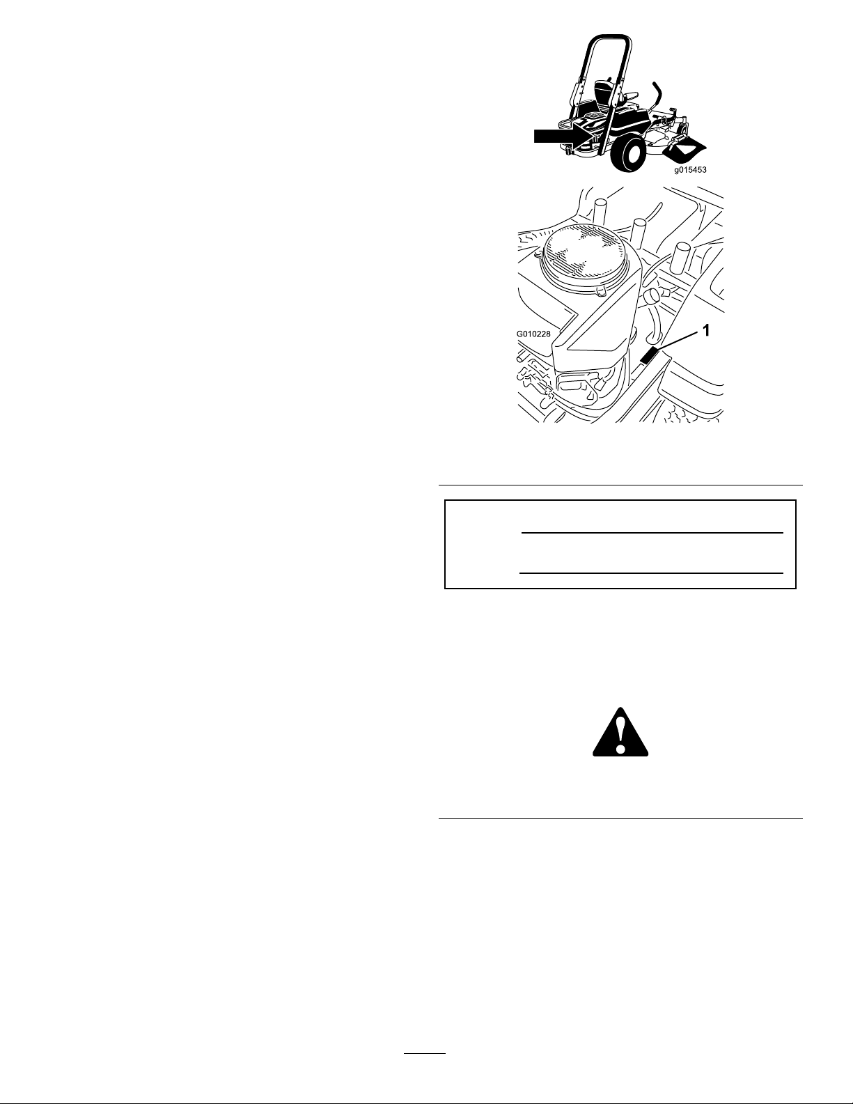
SlopeIndicator
G011841
Figure3
Thispagemaybecopiedforpersonaluse.
1.Themaximumslopeyoucansafelyoperatethemachineonis15degrees.Usetheslopecharttodeterminethedegreeofslope
ofhillsbeforeoperating.Donotoperatethismachineonaslopegreaterthan15degrees.Foldalongtheappropriateline
tomatchtherecommendedslope.
2.Alignthisedgewithaverticalsurface,atree,building,fencepole,etc.
3.Exampleofhowtocompareslopewithfoldededge.
9
Page 10
SafetyandInstructionalDecals
Safetydecalsandinstructionsareeasilyvisibletotheoperatorandarelocatednearanyareaof
potentialdanger.Replaceanydecalthatisdamagedorlost.
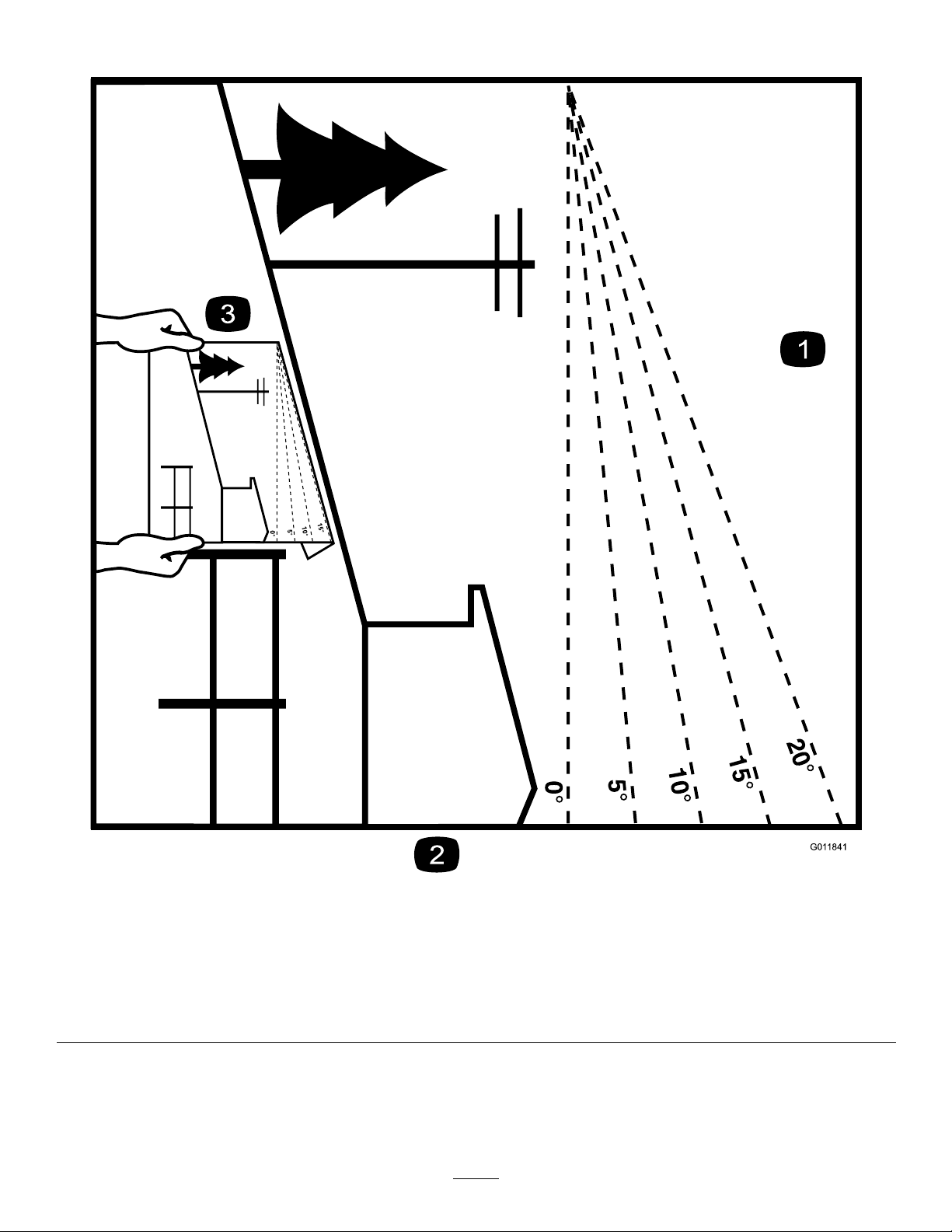
99-8936
1.Machinespeed4.Neutral
2.Fast5.Reverse
3.Slow
110-6691
1.Thrownobjecthazard—keepbystandersasafedistance
fromthemachine.
2.Thrownobjecthazard,mower—donotoperatewithoutthe
deector,dischargecover,orgrasscollectionsystemin
place.
3.Cutting/dismembermentofhandorfoot—stayawayfrom
movingparts.
1.ReadtheOperator's
Manual.
2.Heightofcut
1.Parking
brake—disengaged
112-9840
3.Removetheignitionkey
andreadtheinstructions
beforeservicingor
performingmaintenance.
115-9625
2.Parkingbrake—engaged
107-3069
1.Warning–thereisnorolloverprotectionwhentherollbaris
down.
2.Toavoidinjuryordeathfromarolloveraccident,keepthe
rollbarintheraisedandlockedpositionandweartheseat
belt.Lowertherollbaronlywhenabsolutelynecessary;do
notweartheseatbeltwhentherollbarisdown.
3.ReadtheOperator'sManual;driveslowlyandcarefully.
10
Page 11
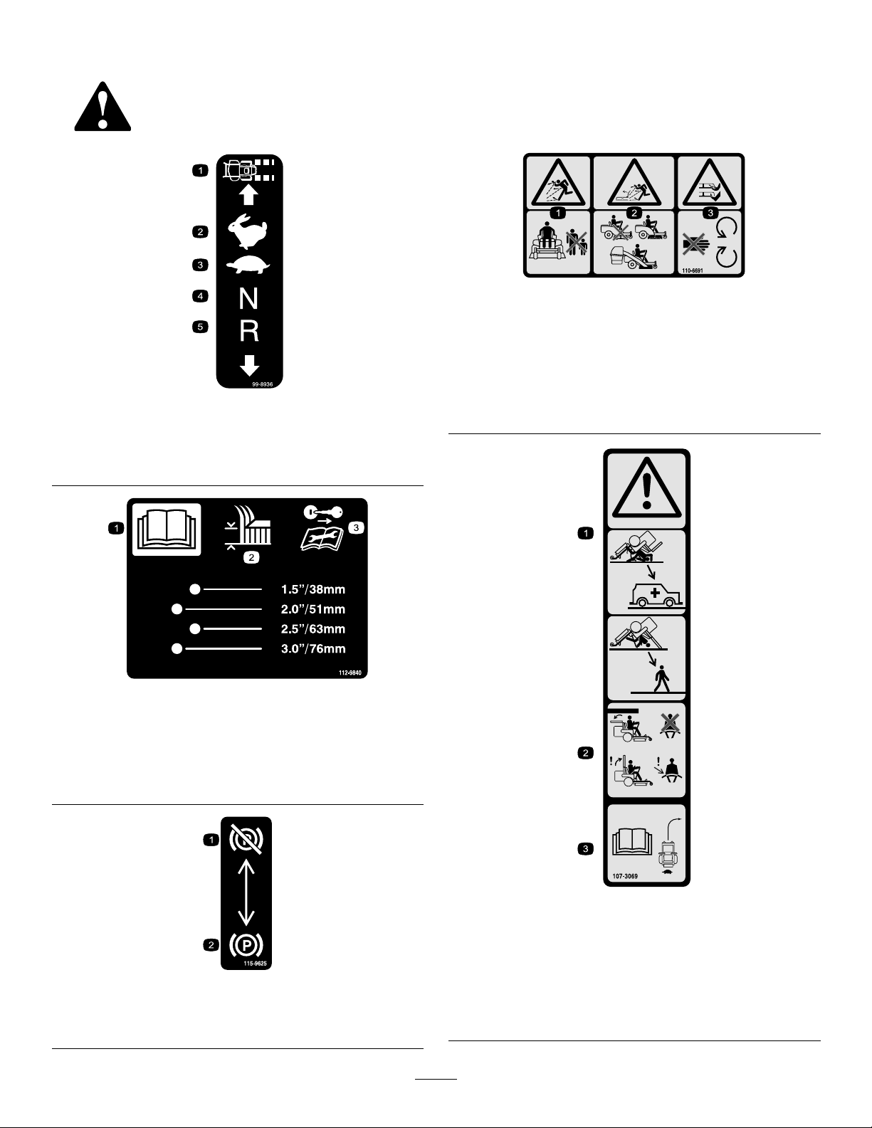
93-7009
1.Warning—donotoperatethemowerwiththedeectorup
orremoved;keepthedeectorinplace.
2.Cutting/dismembermenthazardofhandorfoot,mower
blade—stayawayfrommovingparts.
BatterySymbols
Someorallofthesesymbolsareonyourbattery
115-9644
1.Pressthepedalandlifttheheightofcutlevertounlockthe
deckposition.
2.Heightofcut
3.Pressthepedaltomovethedecktothetransportposition
117-5344
1.Explosionhazard
2.Nore,opename,or
smoking.
3.Causticliquid/chemical
burnhazard
4.Weareyeprotection.9.Flusheyesimmediately
5.ReadtheOperator's
Manual.
6.Keepbystandersasafe
7.Weareyeprotection;
8.Batteryacidcancause
10.Containslead;donot
distancefromthebattery.
explosivegasescan
causeblindnessandother
injuries.
blindnessorsevereburns.
withwaterandgetmedical
helpfast.
discard.
1.Lock
2.ReadtheOperator'sManual
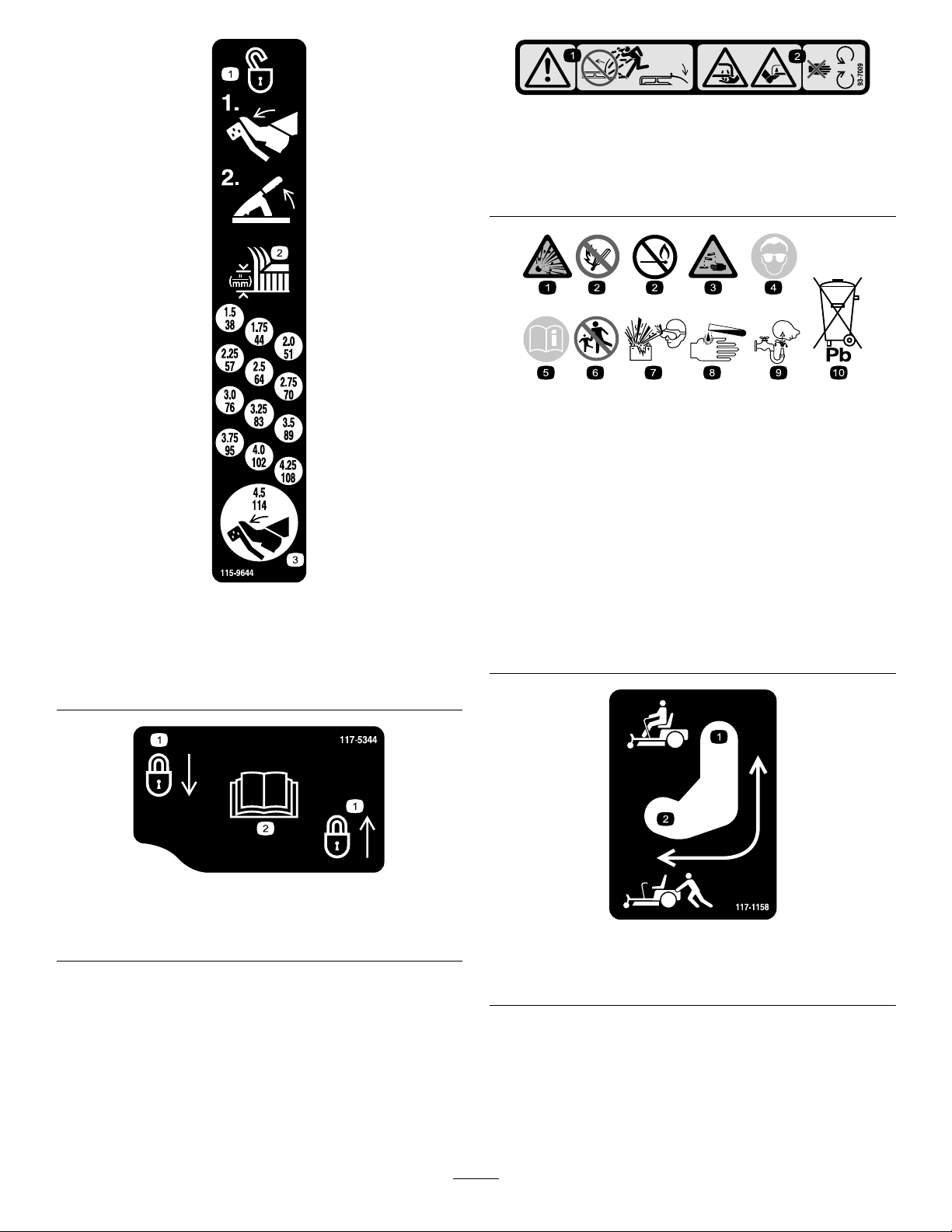
1.Bypassleverpositionfor
operatingthemachine
11
117-1158
2.Bypassleverpositionfor
pushingthemachine
Page 12
Manufacturer'sMark
1.Indicatesthebladeisidentiedasapartfromtheoriginal
machinemanufacturer.
114-1606
1.Entanglementhazard,belt—keepallguardsinplace.
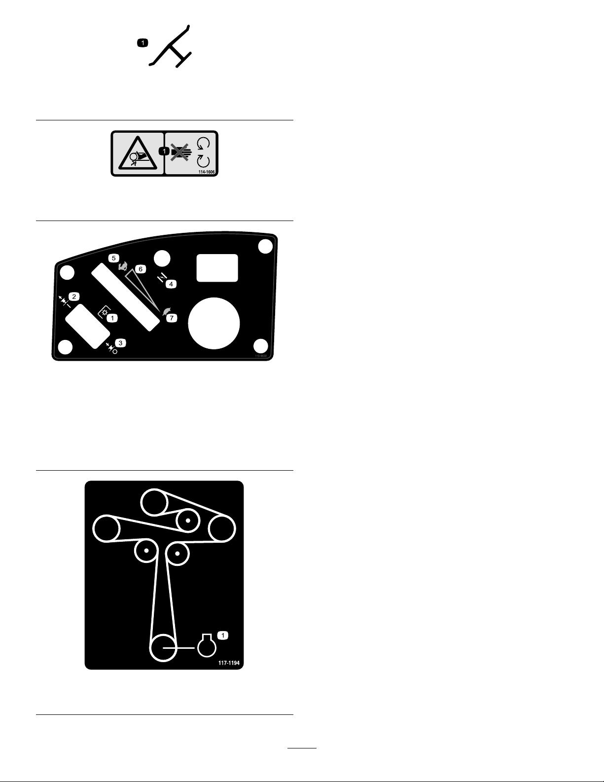
115-9632
1.Powertake-off(PTO),
Bladecontrolswitchon
somemodels
2.Bladecontrolswitch—On6.Continuousvariable
3.Bladecontrolswitch—Off7.Slow
4.Choke
5.Fast
setting
117-1194
1.Engine
12
Page 13
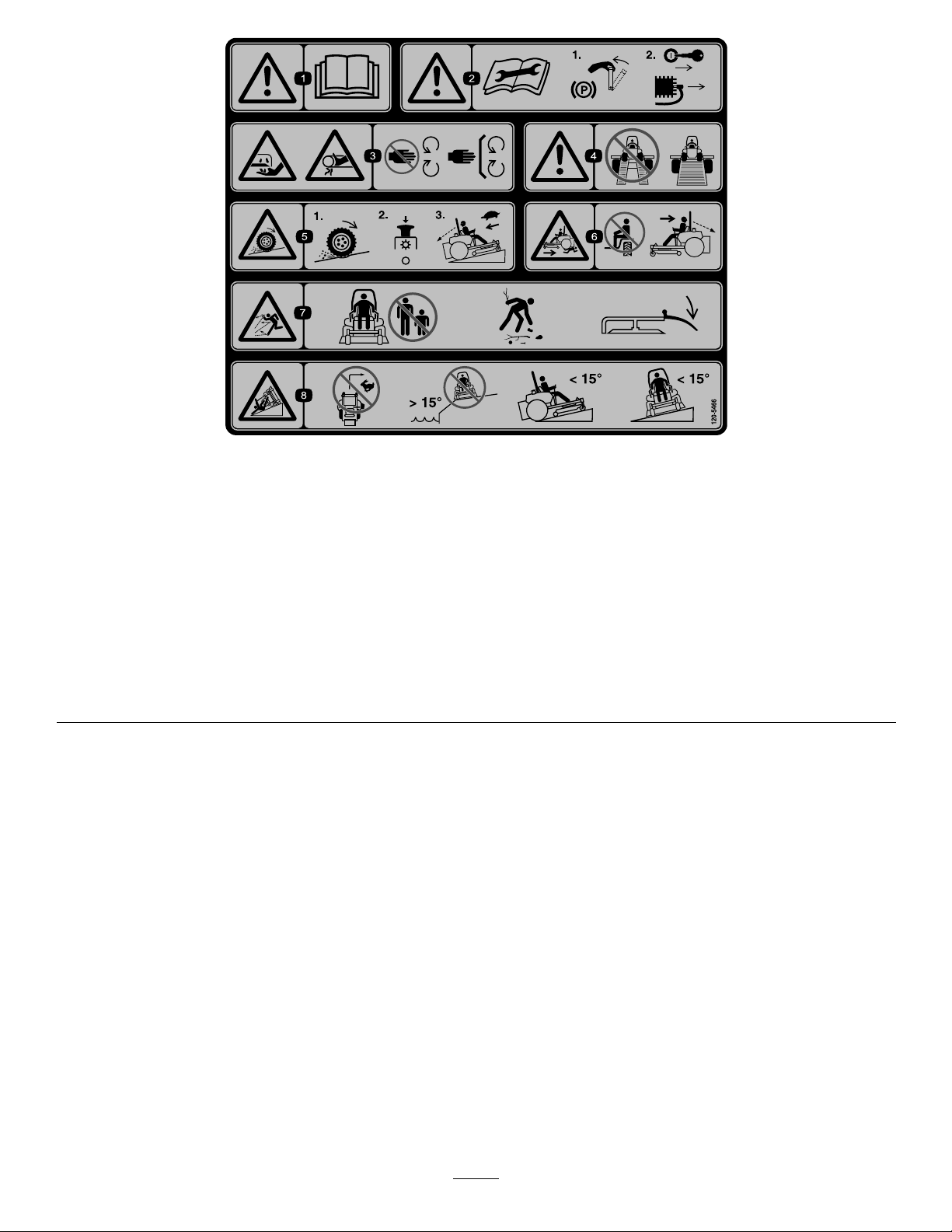
120-5466
1.Warning—readtheOperator'sManual.5.Lossoftraction/controlhazard,slopes—lossoftraction/control
2.Warning—readtheinstructionsbeforeservicingorperforming
maintenance;movethemotioncontrolleverstothepark
(brake)position,removetheignitionkeyanddisconnectthe
sparkplugwire.
3.Cutting/dismembermenthazard,mowerblade;entanglement
hazard,belt—stayawayfrommovingparts,keepallguards
andshieldsinplace.
4.Warning—donotusesplitramps,useafullrampswhen
transportingmachine.
onaslope,disengagethebladecontrolswitch(PTO),
proceedofftheslopeslowly.
6.Crushing/dismembermenthazardofbystanders,
reversing—donotcarrypassengers,lookbehindanddown
whenreversing.
7.Thrownobjecthazard—keepbystandersasafedistancefrom
themachine,pickupdebrisbeforeoperating,keepdeector
inplace.
8.Tippinghazard—donotturnathighspeeds,donotoperate
neardrop-offsonslopesgreaterthan15degrees,donotmow
slopesgreaterthan15degrees,avoidsuddenandsharp
turnswhileonslopes.
13
Page 14

115-9630
1.ReadtheOperator'sManualbeforeperformingany
maintenance.
2.Checktheengineoilevery8hours5.Checkthecasterwheeltirepressureevery25hours
3.Checkthedrivewheeltirepressureevery25hours
4.Checkthehydraulicoilevery25hours
6.Lubricatethecasterwheelevery25hours
119-8983
1.Fuel2.Full
3.Half
4.Empty
14
Page 15

119-8986
1.Fuel2.Full
3.Half
4.Empty
15
Page 16
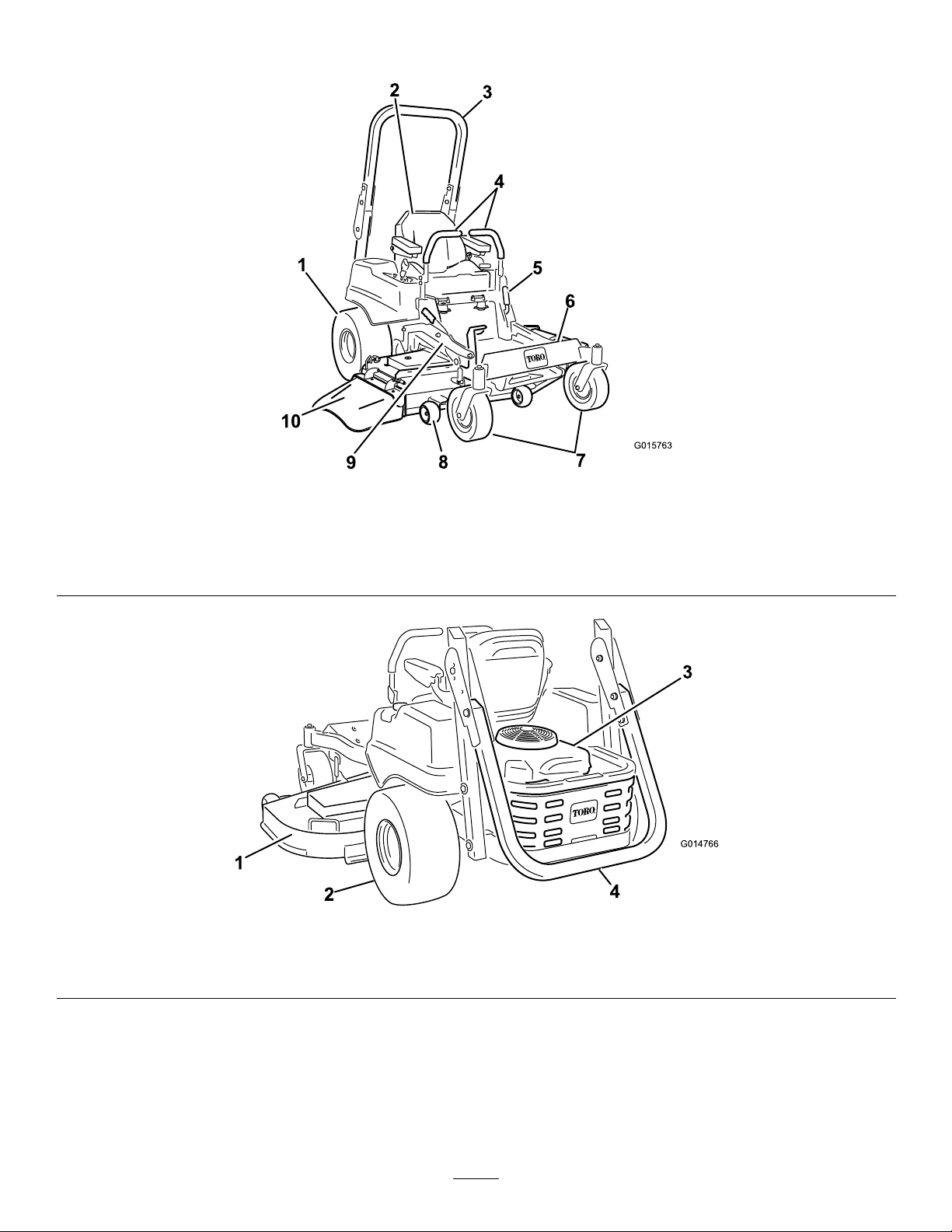
ProductOverview
G015763
1
2
3
4
5
6
7
8
9
10
G014766
1
2
3
4
Figure4
1.Drivewheel4.Motioncontrollevers7.Frontcasterwheel
2.Operatorseat
3.Rolloverprotectionsystem
(ROPS)
1.MowerDeck3.Engine
2.Drivewheel
5.Parkingbrake8.Anti-scalproller
6.Footrest
9.Footpedaldeckliftand
height-of-cut
Figure5
4.Rolloverprotectionsystem(ROPS),foldeddown
10.Deector
16
Page 17
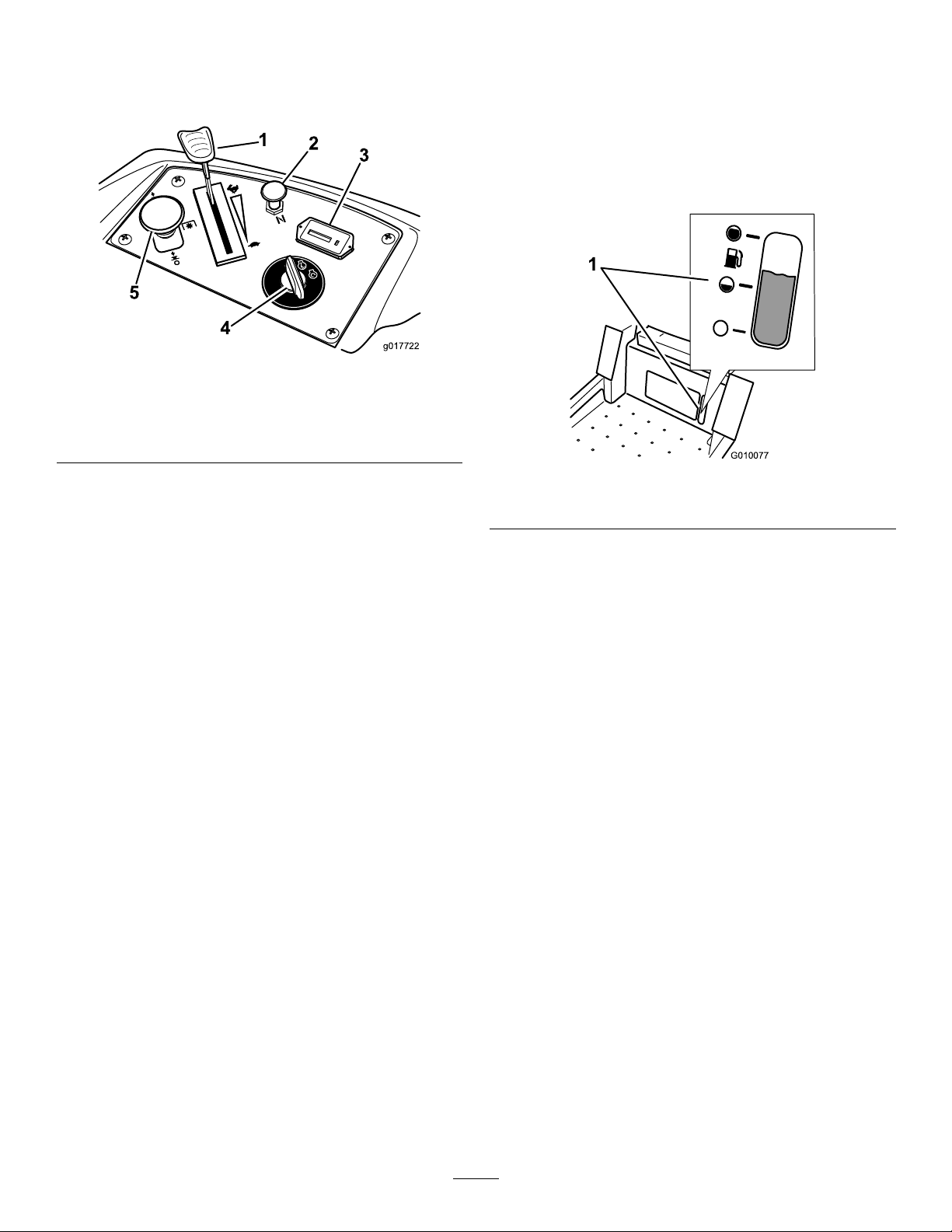
Controls
g017722
1
2
3
4
5
G010077
1
Becomefamiliarwithallthecontrolsbeforeyoustart
theengineandoperatethemachine(Figure6).
Figure6
1.Throttlecontrol4.Ignitionswitch
2.Choke5.Bladecontrolswitch(PTO)
3.Hourmeter
switch(PTO)isengaged.Usethesetimesforscheduling
regularmaintenance(
Figure6).
FuelGauge
Thefuelwindowlocatedbelowtheoperatorposition
canbeusedtoverifythelevelofgasolineinthetank
(Figure7).
Figure7
IgnitionSwitch
Theignitionswitchhasthreepositions:Start,Run
andOff.ThekeywillturntoStartandmovebackto
Runuponrelease.TurningthekeytotheOffposition
willstoptheengine;however,alwaysremovethekey
whenleavingthemachinetopreventtheenginefrom
accidentallystarting(
Figure6).
ThrottleControl
ThethrottlecontrolisvariablebetweenFastandSlow.
Movingthrottleleverforwardwillincreaseenginespeed
andmovingthrottlelevertotherearwilldecreaseengine
speed.Movingthethrottleforwardintothedetentis
fullthrottle(
Figure6).
Choke
Usethechoketostartacoldengine.Pullthechoke
knobuptoengageit.Pushdownonthechokeknob
todisengageit.
1.Fuelgaugewindow
MotionControlLevers
Themotioncontrolleversarespeedsensitivecontrols
ofindependentwheelmotors.Movingaleverforward
orbackwardturnsthewheelonthesamesideforward
orinreverse;wheelspeedisproportionaltotheamount
theleverismoved.Movethecontrolleversoutward
fromthecentertotheneutrallockpositionandexitthe
machine(
Figure4).Alwayspositionthemotioncontrol
leversintotheneutrallockpositionwhenyoustopthe
machineorleaveitunattended.
ParkingBrakeLever
Locatedonleftsideoftheconsole(Figure4).Thebrake
leverengagesaparkingbrakeonthedrivewheels.Pull
theleverupandrearwardtoengagethebrake.Pushthe
leverforwardanddowntodisengagethebrake.
BladeControlSwitch(PowerTake-Off)
Thebladecontrolswitch,representedbyapower
take-off(PTO)symbol,engagesanddisengagespower
tothemowerblades(Figure6).
HourMeter
Thehourmeterrecordsthenumberofhourstheblades
haveoperated.Itoperateswhenthebladecontrol
FootPedalDeckLiftSystem
Thefootpedaldeckliftsystemallowstheoperator
tolowerandraisethedeckfromtheseatedposition.
Theoperatorcanusethefootpedaltoliftthedeck
brieytoavoidobstaclesorlockthedeckinthehighest
height-of-cutortransportposition(Figure4).
17
Page 18

Height-of-CutLever
Theheight-of-cutleverworkswiththefootpedalto
lockthedeckinaspeciccuttingheight.Onlyadjustthe
heightofcutwhilemachineisnotmoving(Figure4).
Operation
Note:Determinetheleftandrightsidesofthe
machinefromthenormaloperatingposition.
Attachments/Accessories
AselectionofToroapprovedattachmentsand
accessoriesareavailableforusewiththemachineto
enhanceandexpanditscapabilities.Contactyour
AuthorizedServiceDealerorDistributororgoto
www.Toro.comforalistofallapprovedattachments
andaccessories.
ThinkSafetyFirst
Pleasecarefullyreadallofthesafetyinstructionsand
decalsinthesafetysection.Knowingthisinformation
couldhelpyou,yourfamily,petsorbystandersavoid
injury.
DANGER
Mowingonwetgrassorsteepslopescancause
slidingandlossofcontrol.
Wheelsdroppingoveredgescancauserollovers,
whichmayresultinseriousinjury,deathor
drowning.
Alossoftractionisalossofsteeringcontrol.
Toavoidlossofcontrolandpossibilityofrollover:
•Donotmowneardrop-offsornearwater.
•Donotmowslopesgreaterthan15degrees.
•Reducespeedanduseextremecautionon
slopes.
•Whenmowingslopes,graduallyworkfrom
lowertohigherareasontheincline.
•Avoidsuddenturnsorrapidspeedchanges.
•Turnup,intoaninclinewhenchanging
directionsonslopes.Turningdowntheslope
reducestraction.
•Attachmentschangethehandling
characteristicsofthemachine.Use
extracautionwhenusingattachmentswiththe
machine.
18
Page 19
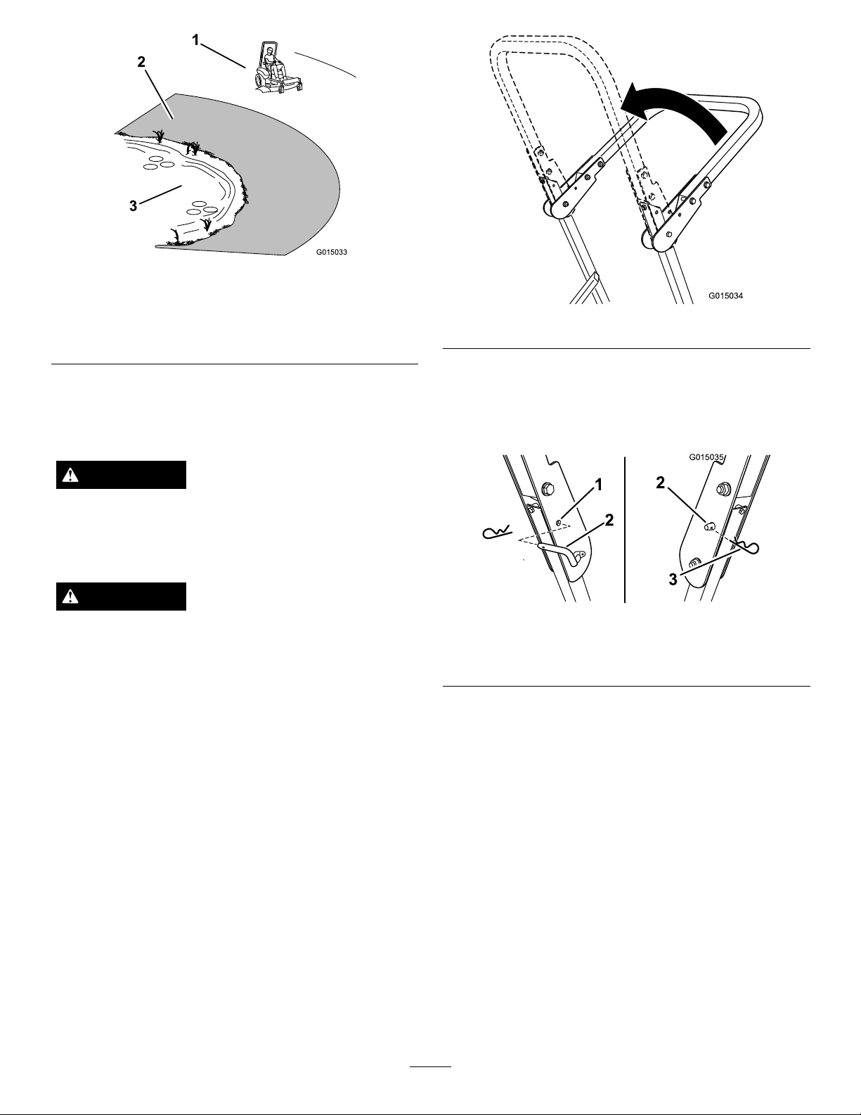
G015033
1
2
3
Figure8
G015034
G015035
1
2
3
2
1.SafeZone-usethemachinehere
2.Usewalkbehindmowerand/orhandtrimmerneardrop-offs
andwater.
3.Water
UsingtheRolloverProtection
System(ROPS)
WARNING
Toavoidinjuryordeathfromrollover:keepthe
rollbarintheraisedlockedpositionandusethe
seatbelt.
WARNING
Thereisnorolloverprotectionwhentherollbar
isinthedownposition.
•Lowertherollbaronlywhenabsolutely
necessary.
•Donotweartheseatbeltwhentherollbaris
inthedownposition.
•Driveslowlyandcarefully.
•Raisetherollbarassoonasclearancepermits.
•Checkcarefullyforoverheadclearances(i.e.
branches,doorways,electricalwires)before
drivingunderanyobjectsanddonotcontact
them.
Important:Lowertherollbaronlywhen
absolutelynecessary.
1.Toraisetherollbar,removethehaircotterpinand
removethelockingpins.
2.Raisetherollbartotheuprightposition(Figure9).
Figure9
Important:Alwaysusetheseatbeltwiththe
rollbarintheraisedposition.
3.Installthelockingpins.Securethepinsbyinstalling
thehaircotterpin(Figure10).
Figure10
1.HoleinROPS
2.Lockingpin
3.Hairpincotter
4.Tolowertherollbar,removethehaircotterpinand
removethelockingpin.(Figure10).
5.Lowertherollbartothedownposition.
6.Usethetwolockingandcotterpinstosecurethe
bar.
AddingFuel
•Forbestresults,useonlyclean,fresh,unleaded
gasolinewithanoctaneratingof87orhigher
((R+M)/2ratingmethod).
•Oxygenatedfuelwithupto10%ethanolor15%
MTBEbyvolumeisacceptable.
•DoNotuseethanolblendsofgasoline(suchasE15
orE85)withmorethan10%ethanolbyvolume.
Performanceproblemsand/orenginedamagemay
resultwhichmaynotbecoveredunderwarranty.
19
Page 20

•DoNotusegasolinecontainingmethanol.
•DoNotstorefueleitherinthefueltankorfuel
containersoverthewinterunlessafuelstabilizeris
used.
•DoNotaddoiltogasoline.
DANGER
Incertainconditionsduringfueling,static
electricitycanbereleasedcausingasparkwhich
canignitethegasolinevapors.Areorexplosion
fromgasolinecanburnyouandothersandcan
damageproperty.
•Alwaysplacegasolinecontainersontheground
awayfromyourvehiclebeforelling.
•Donotllgasolinecontainersinsideavehicle
oronatruckortrailerbedbecauseinterior
carpetsorplastictruckbedlinersmayinsulate
thecontainerandslowthelossofanystatic
charge.
•Whenpractical,removegas-powered
equipmentfromthetruckortrailerandrefuel
theequipmentwithitswheelsontheground.
•Ifthisisnotpossible,thenrefuelsuch
equipmentonatruckortrailerfromaportable
container,ratherthanfromagasolinedispenser
nozzle.
•Ifagasolinedispensernozzlemustbeused,
keepthenozzleincontactwiththerimofthe
fueltankorcontaineropeningatalltimesuntil
fuelingiscomplete.
DANGER
Incertainconditions,gasolineisextremely
ammableandhighlyexplosive.Areorexplosion
fromgasolinecanburnyouandothersandcan
damageproperty.
•Fillthefueltankoutdoors,inanopenarea,
whentheengineiscold.Wipeupanygasoline
thatspills.
•Neverllthefueltankinsideanenclosedtrailer.
•Donotllthefueltankcompletelyfull.Add
gasolinetothefueltankuntilthelevelis1/4to
1/2inch(6to13mm)belowthebottomofthe
llerneck.Thisemptyspaceinthetankallows
gasolinetoexpand.
•Neversmokewhenhandlinggasoline,andstay
awayfromanopenameorwheregasoline
fumesmaybeignitedbyaspark.
•Storegasolineinanapprovedcontainerand
keepitoutofthereachofchildren.Neverbuy
morethana30-daysupplyofgasoline.
•Donotoperatewithoutentireexhaustsystem
inplaceandinproperworkingcondition.
UsingStabilizer/Conditioner
Useafuelstabilizer/conditionerinthemachineto
providethefollowingbenets:
•Keepsgasolinefreshduringstorageof90daysor
less.Forlongerstorageitisrecommendedthatthe
fueltankbedrained.
WARNING
Gasolineisharmfulorfatalifswallowed.
Long-termexposuretovaporscancauseserious
injuryandillness.
•Avoidprolongedbreathingofvapors.
•Keepfaceawayfromnozzleandgastankor
conditioneropening .
•Keepgasawayfromeyesandskin.
•Cleanstheenginewhileitruns
•Eliminatesgum-likevarnishbuildupinthefuel
system,whichcauseshardstarting
Important:Donotusefueladditivescontaining
methanolorethanol.
Addthecorrectamountofgasstabilizer/conditioner
tothegas.
Note:Afuelstabilizer/conditionerismosteffective
whenmixedwithfreshgasoline.Tominimizethe
chanceofvarnishdepositsinthefuelsystem,usefuel
stabilizeratalltimes.
FuelGauge
Usethefuelwindowbelowtheoperatortoverifythe
levelofgasolinebeforellingthetank(Figure11).
20
Page 21

G010077
1
Figure11
G010475
1
2
4
3
G010078
1
2
1.Fuelgaugewindow
FillingtheFuelT ank
Makesuretheengineisshutoffandthemotion
controlsareintheparkposition.
Important:DoNotoverllfueltank.Fillthe
fueltanktothebottomofthellerneck.The
emptyspaceinthetankallowsthefueltoexpand.
Overllingmayresultinfuelleakageordamageto
theengineoremissionsystem.
Figure12
3.Installthefueltankcapsecurelyandtightenuntilit
“clicks”.Wipeupanygasolinethatmayhavespilled.
1.Cleanaroundthefueltankcapandremovethecap.
Note:Youcanusethefuelwindowbelowthe
operatingpositionverifythepresenceofgasoline
beforellingthetank(
2.Slowlyaddregular,unleadedgasolineuntilthefuel
reachesthebaseofthellerneckFigure12.
Figure11).
CheckingtheEngineOilLevel
Beforeyoustarttheengineandusethemachine,check
theoillevelintheenginecrankcase;refertoChecking
theEngineOilLevel.
OperatingtheParkingBrake
Alwayssettheparkingbrakewhenyoustopthe
machineorleaveitunattended.
SettingtheParkingBrake
Figure13
21
Page 22

ReleasingtheParkingBrake
G010079
1
2
G008946
G008959
1
2
START
RUN
STOP
G008947
Figure14
OperatingtheThrottle
ThethrottlecontrolcanbemovedbetweenFastand
Slowpositions(Figure15).
Alwaysusethefastpositionwhenturningonthe
mowerdeckwiththebladecontrolswitch(PTO).
Figure15
OperatingtheChoke
Usethechoketostartacoldengine.
1.Iftheengineiscold,usethechoketostartthe
engine.
2.Pulluponthechokeknobtoengagethechoke
beforeusingtheignitionswitch(
Figure16).
Figure16
1.On2.Off
OperatingtheIgnitionSwitch
1.TurntheignitionkeytotheStartposition
(Figure17).Whentheenginesstarts,releasethekey.
Important:Donotengagestarterformore
than5secondsatatime.Iftheenginefails
tostartallowa15secondcool-downperiod
betweenattempts.Failuretofollowthese
instructionscanburnoutthestartermotor.
Note:Additionalstartingcyclesmayberequired
whenstartingtheengineforthersttimeafterthe
fuelsystemhasbeenwithoutfuelcompletely.
3.Pushdownonthechoketodisengagethechoke
aftertheenginehasstarted(
Figure16).
Figure17
2.Turntheignitionkeytostoptostoptheengine.
22
Page 23

StartingandStoppingthe
G010080
2
3
4
5
1
START
RUN
STOP
G008947
Engine
StartingtheEngine
1.Sitdownontheseat(Figure18)andfastentheseat
belt.
2.Movethemotioncontrolsoutwardtotheneutral
lockposition(
3.Settheparkingbrake(Figure18);refertoSetting
theParkingBrake.
4.Movethebladecontrolswitch(PTO)totheOff
position(Figure18).
Figure18).
betweenattempts.Failuretofollowthese
instructionscanburnoutthestartermotor.
Note:Additionalstartingcyclesmayberequired
whenstartingtheengineforthersttimeafterthe
fuelsystemhasbeenwithoutfuelcompletely.
5.MovethethrottlelevertoFast.
6.EngagethechokeasdescribedinOperatingthe
Choke.
Note:Awarmorhotenginemaynotrequire
choking.Inthiscase,rsttrystartingtheengine
withoutusingthechoke.
Figure19
1.Off3.Start
2.Run
StoppingtheEngine
CAUTION
Childrenorbystandersmaybeinjuredifthey
moveorattempttooperatethetractorwhileitis
unattended.
Alwaysremovetheignitionkeyandsettheparking
brakewhenleavingthemachineunattended,even
ifjustforafewminutes.
7.TurntheignitionkeytotheStartposition
(Figure17).Whentheenginesstarts,releasethekey.
Important:Donotengagestarterformore
than5secondsatatime.Iftheenginefails
tostartallowa15secondcool-downperiod
Figure18
23
Page 24

S
T
A
R
T
R
U
N
S
T
O
P
G017771
2
3
4
5
1
G008945
Figure21
G009174
DisengagingtheBladeControlSwitch
(PTO)
Figure22
Figure20
OperatingtheMowerBlade
ControlSwitch(PTO)
Thebladecontrolswitch(PTO)startsandstopsthe
mowerbladesandanypoweredattachments.
EngagingtheBladeControlSwitch
(PTO)
Engagethebladecontrolswitch(PTO)withthethrottle
positionatFast.
Note:Engagingthebladecontrolswitch(PTO)with
thethrottlepositionathalforlesswillcauseexcessive
weartothedrivebelts.
TheSafetyInterlockSystem
WARNING
Ifsafetyinterlockswitchesaredisconnectedor
damagedthemachinecouldoperateunexpectedly
causingpersonalinjury.
•Donottamperwiththeinterlockswitches.
•Checktheoperationoftheinterlockswitches
dailyandreplaceanydamagedswitchesbefore
operatingthemachine.
UnderstandingtheSafetyInterlock
System
Thesafetyinterlocksystemisdesignedtopreventthe
enginefromstartingunless:
•Theparkingbrakeisengaged.
•Thebladesaredisengaged.
•Themotioncontrolleversareintheneutrallock
position.
Thesafetyinterlocksystemalsoisdesignedtostopthe
enginewhenthecontrolleversareoutoftheneutral
lockpositionwiththeparkingbrakeonorifyourise
fromtheseatwhenthebladesareengaged.
24
Page 25

TestingtheSafetyInterlockSystem
Testthesafetyinterlocksystembeforeyouusethe
machineeachtime.Ifthesafetysystemdoesnot
operateasdescribedbelow,haveanAuthorizedService
Dealerrepairthesafetysystemimmediately.
1.Whilesittingontheseat,engagetheparkingbrake
andmovethebladecontrolswitchtoOn.Try
startingtheengine;theengineshouldnotcrank.
2.Whilesittingontheseat,engagetheparkingbrake
andmovethebladecontrolswitchtoOff.Move
eithermotioncontrollever(forwardorreverse).
Trystartingtheengine;theengineshouldnotcrank.
Repeatwiththeothermotioncontrollever.
3.Whilesittingontheseat,engagetheparkingbrake,
movethebladecontrolswitchtoOff,andlockthe
motioncontrolleversinneutral.Starttheengine.
Whiletheengineisrunning,releasetheparking
brake,engagethebladecontrolswitch,andrise
slightlyfromtheseat;theengineshouldstop.
4.Whilesittingontheseat,engagetheparkingbrake,
movethebladecontrolswitchtoOff,andlockthe
motioncontrolleversinneutral.Starttheengine.
Whiletheengineisrunning,centerthemotion
controls;theengineshouldstop.
DrivingForwardorBackward
Thethrottlecontrolregulatestheenginespeedas
measuredinrpm(revolutionsperminute).Place
thethrottlecontrolinthefastpositionforbest
performance.Alwaysoperateinthefullthrottle
positionwhenmowing.
UsingtheMotionControlLevers
Figure23
1.Motioncontrol
lever-neutrallockposition
2.Center,unlockedposition5.Frontofmachine
3.Forward
4.Backward
DrivingForward
Note:Theenginewillkillifthetractioncontrollevers
aremovedwiththeparkingbrakeengaged.
CAUTION
Machinecanspinveryrapidly.Operatormaylose
controlofmachineandcausepersonalinjuryor
damagetomachine.
•Usecautionwhenmakingturns.
•Slowthemachinedownbeforemakingsharp
turns.
1.Releasetheparkingbrake;refertoReleasingthe
ParkingBrakeinOperation.
2.Movetheleverstothecenter,unlockedposition.
3.Togoforward,slowlypushthemotioncontrol
leversforward(
25
Figure24).
Page 26

G008952
Figure24
G008953
G010219
bladecontrolswitch(PTO),andturntheignitionkey
tooff.
Settheparkingbrakewhenyouleavethemachine;refer
toSettingtheParkingBrake.Remembertoremovethe
keyfromtheignitionswitch.
CAUTION
Childrenorbystandersmaybeinjuredifthey
moveorattempttooperatethetractorwhileitis
unattended.
Alwaysremovetheignitionkeyandsettheparking
brakewhenleavingthemachineunattended,even
ifjustforafewminutes.
AdjustingtheHeightofCut
Themachineisequippedwithafootpedaldecklift
system.Theoperatorcanusethefootpedaltolift
thedeckbrieytoavoidobstaclesorlockthedeckin
thehighestheight-of-cutortransportposition.The
operatorcanusetheheightofcutleverwiththefoot
pedaltolockthedeckinaspeciccuttingheight.
DrivingBackward
1.Movetheleverstothecenter,unlockedposition.
2.Togobackward,slowlypullthemotioncontrol
leversrearward(Figure25).
UsingtheFootPedalDeckLiftSystem
Pressthepedaldowntoraisethedeck;continueto
pressthepedaluntilthedeckislockedinthetransport
positionFigure26.Pushonthedeckliftpedalwith
yourfootandraisetheheight-of-cutleverslightlyto
disengagethetransportlock.
Figure25
StoppingtheMachine
Tostopthemachine,movethetractioncontrollevers
toneutralandmovetolockedposition,disengagethe
Figure26
TransportLockPosition
26
Page 27

AdjustingtheHeight-of-Cut
G010236
1
2
3
4
5
G010233
1
2
3
4
Theheight-of-cutcanbeadjustedfrom1-1/2to
4-1/2inch(38to114mm)in1/4inch(6mm)
incrementsbyrelocatingtheheight-of-cutpininto
differentholelocations.
1.Pushonthedeckliftpedalwithyourfootandraise
themowerdecktothetransportposition(also
the4-1/2inch(114mm)cuttingheightposition)
Figure27).
(
2.Toadjust,removethepinfromtheheight-of-cut
bracket(Figure27).
3.Selectaholeintheheight-of-cutsystem
correspondingtotheheight-of-cutdesiredand,
insertthepin(
4.Pushonthedeckliftpedalwithyourfootandraise
theheight-of-cutleverslightlytodisengagethe
transportlock.Lowerthedeckslowlyuntilthepin
makescontactwiththelever.
Figure27).
2.Removethepinfromtheheight-of-cutbracket
(
Figure27).
3.Selectthelowerholeonthelockdecalandinsert
thepin(
Figure27).
Tolockthedeckinthelowestheight-of-cut
position:
1.Pushonthedeckliftpedalwithyourfootand
raisethemowerdecktothetransportposition
(alsothe4.5inch(114mm)cuttingheightposition)
Figure27).
(
2.Removethepinfromtheheight-of-cutbracket
(Figure27).
3.Pushonthedeckliftpedalwithyourfootandlower
themowerdecktothelowestposition.
4.Selecttheupperholeonthelockdecalandinsert
thepin(
Figure27).
AdjustingtheAnti-Scalp
Rollers
Figure27
1.Deckliftpedal
2.Cutheightpin
3.Height-of-cutpositions
4.Lockposition.lowest
height-of-cut(useonlyfor
deckremoval)
5.Lockposition.transport
position
UsingtheLockPositions
Thedeckcanbelockedinthehighestheight-of-cutor
transportpositionorthelowestheight-of-cutposition.
Tolockthedeckinthetransportposition:
1.Pushonthedeckliftpedalwithyourfootand
raisethemowerdecktothetransportposition
(alsothe4.5inch(114mm)cuttingheightposition)
(Figure27).
Wheneveryouchangetheheight-of-cut,itis
recommendedtoadjusttheheightoftheanti-scalp
rollers.
1.Disengagethebladecontrolswitch(PTO),move
themotioncontrolleverstotheneutrallock
positionandsettheparkingbrake.
2.Stoptheengine,removethekey ,andwaitforall
movingpartstostopbeforeleavingtheoperating
position.
Figure28
1.Anti-scalproller3.FlangeNut
2.Bolt4.Holespacing
PositioningtheSeat
Theseatcanmoveforwardandbackward.Positionthe
seatwhereyouhavethebestcontrolofthemachine
andaremostcomfortable.
27
Page 28

Whilesittingintheoperator'sposition,raisetheseat
G010232
1
4
1
2
G015764
3
5
G012087
2
3
4
1
adjustmentleverslightlyandmovetheseatforwardor
backwardtothedesiredposition(Figure29).
Figure29
1.Adjustmentlever
1.Loosentheupperboltholdingthecontrolleverto
thecontrolarmshaft.
2.Loosenthelowerboltjustenoughtopivotthe
controlleverforeoraft.Tightenbothboltsto
securethecontrolinthenewposition.
3.Repeattheadjustmentfortheoppositecontrol
lever.
PushingtheMachinebyHand
Important:Alwayspushthemachinebyhand.
Nevertowthemachinebecausedamagemay
occur.
ToPushtheMachine
1.Parkthemachineonalevelsurfaceanddisengage
thebladecontrolswitch.
AdjustingtheMotionControl
Levers
AdjustingtheHeight
Themotioncontrolleverscanbeadjustedhigheror
lowerformaximumoperatorcomfort.
1.Removethe2boltsand2washersholdingthe
controllevertothecontrolarmshaft(
2.Movethecontrollevertothenextsetofholes.
Securetheleverwiththe2boltsand2washers
(Figure30).
Figure30).
2.Movethemotioncontrolleversoutwardtoneutral
lockposition,stoptheengine,removethekey,and
waitforallmovingpartstostopbeforeleavingthe
operatingposition.Makesuretheparkingbrakeis
disengaged.
3.Locatethebypassleversattherearofthemachine,
ontheleftandrightsideoftheframe.
4.Movethebypassleversrearwardandthendown
tolocktheminplaceasshownin
disengagethewheelmotors.Repeatthisoneach
sideofthemachine.
Themachineisnowabletobepushedbyhand.
Figure31to
Figure30
1.Controlarmshaft
2.Controllever
3.Slotted,upperhole
3.Repeattheadjustmentfortheoppositecontrol
lever.
AdjustingtheTilt
Themotioncontrolleverscanbetiltedforeoraftfor
maximumoperatorcomfort.
4.Washer
5.Bolt
Figure31
28
Page 29

ToOperatetheMachine
1
1
2
3
G012841
G012806
1
2
3
4
3
2
Movethebypasstothepositionforoperatingthe
machine(Figure31)toengagethewheelmotors.
Convertingthe48inchMower
toSideDischarge
Themowerdeckandmowerbladesshippedwith
thismachineweredesignedforoptimummulching
performance.Sidedischargeperformancecanbe
improvedbyreplacingthemulchingbladeswith
standardcuttingbladesobtainedfromyourlocal
authorizedTorodealer.Tomaintainoptimummulching
performance,alwaysinstallthemulchingbladesthatare
shippedwiththisunitwhenchangingbacktomulching
operation.
Figure32
1.Locknut(5/16inch)3.Leftbafe
2.Carriagebolt(5/16x3/4
inch)
Installthefastenersintothesameholesinthedeckthey
wereoriginallyremovedfrom.Thisensurenoholesare
leftopenwhenthedeckisoperated.
DANGER
Openholesinthemowerexposeyouandothersto
throwndebris.Debristhrownoutofholesinthe
mowercancauseinjury.
•Neveroperatethemowerwithouthardware
mountedinallholesinthemower.
•Installhardwareinmountingholeswhenthe
bafeisremoved.
RemovingtheMulchBafe
1.Parkthemachineonalevelsurfaceanddisengage
thebladecontrolswitch.
2.Movethemotioncontrolleversoutwardtothe
neutrallockposition,settheparkingbrake,stop
theengine,removethekey ,andwaitforallmoving
partstostopbeforeleavingtheoperatingposition.
3.RemovethemowerasdescribedintheRemoving
theMowerprocedureintheMaintenancesectionfor
moreinformation.
4.Turnthemowerupsidedown.
5.Removetheexistingmowerbladesinstalledonyour
deck.RefertotheRemovingtheBladesprocedure
intheMaintenancesectionformoreinformation.
6.Removethetwolocknuts(5/16inch)securedto
theweldedpostsoftheleftbafeonthetopof
themowerdeckatthecenterandleftofcenter
positions(
Figure32).Removethecarriageboltand
locknutonthesidewallofthemowerdecksecuring
theleftbafetothedeck.
7.Removetheleftbafefromthemowerdeckas
showninFigure32.
8.Removethecarriagebolt(5/16x3/4inch)and
locknut(5/16inch)ontherearwallofthemower
decksecuringthebafetothedeck(
Figure33
1.Bafeguard3.Carriagebolt(5/16x3/4
inch)
2.Locknut(5/16inch)4.Rightbafe
Figure33).
9.Locatethebafeguardatthefrontedgeoftheside
dischargeopening.Removethefastenerssecuring
thebafeguardandtherightbafetothemower
deckasshowninFigure33.Removethebafe
guardandretainallfasteners.
10.Removethetwolocknuts(5/16inch)tosecuring
theweldedpostsoftherightbafetothetopofthe
mowerdeckatcenterandrightofcenterpositions
29
Page 30

(Figure34).Removetherightbafefromthe
1
2
3
G012805
G012800
1
2
3
4
mowerdeck.
Figure34
1.Locknut(5/16inch)3.Weldedposts,rightbafe
2.Rightbafe
11.Locatethecutoffbafeintheloosepartsbag.
Removethefastenersattherearholesofthe
dischargeplate.Installthebafeattheside
dischargeopeningonthemowerdeck(Figure35).
Note:Standardcuttingbladeswillimprove
dischargeperformanceandcanobtainedfromyour
localauthorizedTorodealer.
14.InstallthemowerasdescribedintheInstallingthe
MowerprocedureintheMaintenancesectionfor
moreinformation.
Convertingthe54inchMower
toSideDischarge
Themowerdeckandmowerbladesshippedwith
thismachineweredesignedforoptimummulching
performance.Sidedischargeperformancecanbe
improvedbyreplacingthemulchingbladeswith
standardcuttingbladesobtainedfromyourlocal
authorizedTorodealer.Tomaintainoptimummulching
performance,alwaysinstallthemulchingbladesthatare
shippedwiththisunitwhenchangingbacktomulching
operation.
Installthefastenersintothesameholesinthedeckthey
wereoriginallyremovedfrom.Thisensurenoholesare
leftopenwhenthedeckisoperated.
DANGER
Openholesinthemowerexposeyouandothersto
throwndebris.Debristhrownoutofholesinthe
mowercancauseinjury.
Figure35
1.Carriagebolt,existing3.Cutoffbafe,shipped
2.Rearholesinthe
dischargeplate
loose
4.Locknut,existing
12.Usethefastenersremovedtosecurethecutoff
bafetothedeck.
13.Installthebladestothedeck.RefertotheInstalling
theBladesprocedureintheMaintenancesectionfor
moreinformation.
•Neveroperatethemowerwithouthardware
mountedinallholesinthemower.
•Installhardwareinmountingholeswhenthe
bafeisremoved.
RemovingtheMulchBafe
1.Parkthemachineonalevelsurfaceanddisengage
thebladecontrolswitch.
2.Movethemotioncontrolleversoutwardtothe
neutrallockposition,settheparkingbrake,stop
theengine,removethekey ,andwaitforallmoving
partstostopbeforeleavingtheoperatingposition.
3.RemovethemowerasdescribedintheRemoving
theMowerprocedureintheMaintenancesectionfor
moreinformation.
4.Turnthemowerupsidedown.
5.Removetheexistingmowerbladesinstalledonyour
deck.RefertotheRemovingtheBladesprocedure
intheMaintenancesectionformoreinformation.
6.Removethethreelocknuts(5/16inch)securedto
theweldedpostsoftheleftbafeonthetopofthe
mowerdeckatthecenter,leftofcenterandleft
positions(
Figure36).Removethecarriageboltand
30
Page 31

locknutonthesidewallofthemowerdecksecuring
G011149
1
1
2
3
4
G010712
1
2
4
3
5
6
7
theleftbafetothedeck.
Figure36
1.Locknut(5/16inch)3.Leftbafe
2.Carriagebolt(5/16x3/4
inch)
4.Installfastenershere
7.Removetheleftbafefromthemowerdeckas
showninFigure36.
8.Locatethetwoboltsinloosepartsandusethe
existinglocknuts.Installthesefastenersintothe
holesshownin
Figure36onthemowerdeckto
preventyingdebris.Installtheboltup,throughthe
undersideofthedeckanduseanexistinglocknutto
securefromthetopside.
WARNING
Openholesinthemowerexposeyouandothers
tothrowndebriswhichcancausesevereinjury.
•Neveroperatethemowerwithouthardware
mountedinallholesinthemowerhousing.
•Installthehardwareinthemountingholes
whenyouremovethemulchingbafe.
Figure37
1.Carriagebolt(5/16x3/4
inch)
2.Locknuts,frontof
dischargeplate(reinstall
afterbafeisremoved)
3.Locknut,forwardholein
deck(reinstallafterbafe
isremoved)
4.Bafeguard,54inch
decks
5.Hexheadbolt,forward
holeindeck(reinstallafter
bafeisremoved)
6.Carriagebolts,frontof
dischargeplate(reinstall
afterbafeisremoved)
7.Locknut(5/16inch)
10.Locatethebafeguardatthefrontedgeoftheside
dischargeopening.Removethefastenerssecuring
thebafeguardandtherightbafetothemower
deckasshownin
Figure37.Removethebafe
guardandretainallfasteners.
11.Removethetwolocknuts(5/16inch)securingthe
weldedpostsoftherightbafetothetopofthe
mowerdeckatcenterandrightofcenterpositions
Figure38).
(
9.Removethecarriagebolt(5/16x3/4inch)and
locknut(5/16inch)ontherearwallofthemower
decksecuringthebafetothedeck(Figure37).
12.Removethecarriageboltandlocknutsecuringthe
rightbafetothetopofthemowerdeck.Remove
therightbafefromthemowerdeck(Figure38).
31
Page 32

G010704
1
2
3
Note:Standardcuttingbladeswillimprove
dischargeperformanceandcanobtainedfromyour
localauthorizedTorodealer.
17.InstallthemowerasdescribedintheInstallingthe
MowerprocedureintheMaintenancesectionfor
moreinformation.
UsingtheSideDischarge
Themowerhasahingedgrassdeectorthatdisperses
clippingstothesideanddowntowardtheturf.
DANGER
Figure38
1.Locknut(5/16inch)3.Weldedposts,rightbafe
2.Rightbafe4.Carriagebolt
13.Installthefastenersremovedpreviouslyatthefront
holesinthedischargeplateandforwardholeinthe
Figure37).
deck(
14.Locatethecutoffbafeintheloosepartsbag.
Removethefastenersattherearholesofthe
dischargeplate.Installthebafeattheside
dischargeopeningonthemowerdeck(Figure39).
Withoutagrassdeector,dischargecover,or
completegrasscatcherassemblymountedin
place,youandothersareexposedtobladecontact
andthrowndebris.Contactwithrotatingmower
blade(s)andthrowndebriswillcauseinjuryor
death.
•Neverremovethegrassdeectorfromthe
mowerbecausethegrassdeectorroutes
materialdowntowardtheturf.Ifthe
grassdeectoriseverdamaged,replaceit
immediately.
•Neverputyourhandsorfeetunderthemower.
•Nevertrytoclearthedischargeareaormower
bladesunlessyoumovethebladecontrolswitch
(PTO)totheoffposition,rotatetheignition
keytooffandremovethekey.
•Makesurethegrassdeectorisinthedown
position.
Figure39
1.Carriagebolt3.Cutoffbafe
2.Rearholesinthe
dischargeplate
4.Locknut
15.Usethefastenersremovedtosecurethecutoff
bafetothedeck.
16.Installthebladestothedeck.RefertotheInstalling
theBladesprocedureintheMaintenancesectionfor
moreinformation.
32
Page 33

OperatingTips
FastThrottleSetting
Forbestmowingandmaximumaircirculation,operate
theengineatthefastthrottleposition.Airisrequired
tothoroughlycutgrassclippings,sodonotsetthe
height-of-cutsolowastototallysurroundthemower
byuncutgrass.Alwaystrytohaveonesideofthe
mowerfreefromuncutgrass,whichallowsairtobe
drawnintothemower.
CuttingaLawnfortheFirstTime
Cutgrassslightlylongerthannormaltoensurethe
cuttingheightofthemowerdoesnotscalpanyuneven
ground.However,thecuttingheightusedinthepastis
generallythebestonetouse.Whencuttinggrasslonger
thansixinchestall,youmaywanttocutthelawntwice
toensureanacceptablequalityofcut.
Cut1/3oftheGrassBlade
LongGrass
Ifthegrassiseverallowedtogrowslightlylongerthan
normal,orifitcontainsahighdegreeofmoisture,raise
thecuttingheighthigherthanusualandcutthegrassat
thissetting.Thencutthegrassagainusingthelower,
normalsetting.
WhenStopping
Ifthemachine'sforwardmotionmustbestoppedwhile
mowing,aclumpofgrassclippingsmaydropontoyour
lawn.Toavoidthis,moveontoapreviouslycutarea
withthebladesengaged.
KeeptheUndersideoftheMower
Clean
Cleanclippingsanddirtfromtheundersideofthe
moweraftereachuse.Ifgrassanddirtbuildupinside
themower,cuttingqualitywilleventuallybecome
unsatisfactory.
Itisbesttocutonlyabout1/3ofthegrassblade.
Cuttingmorethanthatisnotrecommendedunless
grassissparse,oritislatefallwhengrassgrowsmore
slowly.
MowingDirection
Alternatemowingdirectiontokeepthegrassstanding
straight.Thisalsohelpsdisperseclippingswhich
enhancesdecompositionandfertilization.
MowatCorrectIntervals
Normally,moweveryfourdays.Butremember,
grassgrowsatdifferentratesatdifferenttimes.So
tomaintainthesamecuttingheight,whichisagood
practice,mowmoreofteninearlyspring.Asthegrass
growthrateslowsinmidsummer,mowlessfrequently.
Ifyoucannotmowforanextendedperiod,rstmow
atahighcuttingheight;thenmowagaintwodayslater
atalowerheightsetting.
CuttingSpeed
BladeMaintenance
Maintainasharpbladethroughoutthecuttingseason
becauseasharpbladecutscleanlywithouttearingor
shreddingthegrassblades.Tearingandshreddingturns
grassbrownattheedges,whichslowsgrowthand
increasesthechanceofdisease.Checkthecutterblades
dailyforsharpness,andforanywearordamage.File
downanynicksandsharpenthebladesasnecessary.If
abladeisdamagedorworn,replaceitimmediatelywith
agenuineTOROreplacementblade.
Toimprovecutquality ,useaslowergroundspeedin
certainconditions.
AvoidCuttingTooLow
Ifthecuttingwidthofthemoweriswiderthanthe
moweryoupreviouslyused,raisethecuttingheightto
ensurethatuneventurfisnotcuttooshort.
33
Page 34

Maintenance
RecommendedMaintenanceSchedule(s)
MaintenanceService
Interval
Aftertherst8hours
Aftertherst50hours
Beforeeachuseordaily
Every25hours
Every50hours
Every100hours
Every200hours
Every400hours
MaintenanceProcedure
•Changetheengineoil.
•Changethehydraulicsystemlterandoil.
•Checkthesafetyinterlocksystem.
•Checktheengineoillevel.
•Cleantheairintakescreen.
•Checkthemowerblades.
•Inspectthegrassdeectorfordamage
•Cleanthemowerhousing.
•Greasealllubricationpoints.
•Checktirepressure.
•Checkthehydraulicoillevelintheexpansiontank.
•Inspectthebeltsforcracksandwear.
•Servicethepaperelement(moreoftenindusty,dirtyconditions).
•Changetheengineoil(moreoftenindusty ,dirtyconditions).
•Checkthesparkplug(s).
•Replacethefuellters(moreoftenunderdusty,dirtyconditions).
•Replacethepaperelement(moreoftenindusty,dirtyconditions).
•Changetheoillter.(moreoftenindusty,dirtyconditions)
•Changethehydraulicsystemlterandoil.
Monthly
Yearlyorbeforestorage
•Checkthebatterycharge.
•Paintchippedsurfaces.
•Checkallmaintenanceprocedureslistedabovebeforestorage.
Important:Refertoyourengineoperator'smanualforadditionalmaintenanceprocedures.
CAUTION
Ifyouleavethekeyintheignitionswitch,someonecouldaccidentlystarttheengineandseriouslyinjure
youorotherbystanders.
Removethekeyfromtheignitionanddisconnectthewirefromthesparkplugbeforeyoudoany
maintenance.Setthewireasidesothatitdoesnotaccidentallycontactthesparkplug.
34
Page 35

Figure40
Locatedontheseatpanunderside
1.ReadtheOperator'sManualbeforeperformingany
maintenance.
2.Checktheengineoilevery8hours5.Checkthecasterwheeltirepressureevery25hours
3.Checkthedrivewheeltirepressureevery25hours
4.Checkthehydraulicoilevery25hours
6.Lubricatethecasterwheelevery25hours
35
Page 36

Premaintenance
G009949
1
Lubrication
Procedures
GreasingtheBearings
RaisingtheSeat
Makesurethemotioncontrolleversarelockedinthe
neutrallockposition.Lifttheseatforward.
Thefollowingcomponentscanbeaccessedbyraising
theseat:
•Servicedecal
•Fuses
•Batteryandcables
ServiceInterval:Every25hours—Greaseall
lubricationpoints.
GreaseType:No.2GeneralPurposeLithiumBase
Grease
1.Parkthemachineonalevelsurfaceanddisengage
thebladecontrolswitch.
2.Movethemotioncontrolleversoutwardtothe
neutrallockposition,stoptheengine,removethe
key,andwaitforallmovingpartstostopbefore
leavingtheoperatingposition.
3.Cleanthegreasettings(
witharag.Makesuretoscrapeanypaintoffofthe
frontofthetting(s).
Figure41andFigure40)
Figure41
1.Frontcastertire
4.Connectagreaseguntoeachtting(Figure40and
Figure41).Pumpgreaseintothettingsuntilgrease
beginstooozeoutofthebearings.
5.Wipeupanyexcessgrease.
36
Page 37

EngineMaintenance
G015155
1
2
3
SAEV iscosityGrades
SAE40
SAE30
SAE10W– 30/ SAE10W– 30
-2002032406080100
-30-20-10010203040
°F
°C
STARTING TEMPERA TURERANGE ANTICIPATEDBEFORENEXT OIL CHANGE
SAE5W– 20
G010686
WARNING
Contactwithhotsurfacesmaycausepersonal
injury.
Keephands,feet,face,clothingandotherbody
partsawaythemuferandotherhotsurfaces.
ServicingtheAirCleaner
CleaningtheElement
ServiceInterval:Every100hours—Servicethepaper
element(moreoftenindusty,dirty
conditions).
Every200hours/Y early(whichever
comesrst)—Replacethepaper
element(moreoftenindusty,dirty
conditions).
1.Lightlytaptheelementonaatsurfacetoremove
dustanddirt.
Note:Servicetheaircleanermorefrequently(every
fewhours)ifoperatingconditionsareextremelydusty
orsandy .
RemovingtheElement
1.Parkthemachineonalevelsurfaceanddisengage
thebladecontrol(PTO).
2.Movethemotioncontrolleverstotheneutrallock
position,settheparkingbrake,stoptheengine,
removethekey,andwaitforallmovingpartstostop
beforeleavingtheoperatingposition.
3.Cleanaroundtheaircleanercovertopreventdirt
fromgettingintotheengineandcausingdamage.
Liftthecoverandremovethehoseclampsecuring
theaircleanerassemblytotheengine(
4.Loosenthehoseclampandremovethepaper
element(
Figure42).
Figure42).
2.Inspecttheelementfortears,anoilylm,and
damagetotheseal.
Important:Nevercleanthepaperelementwith
pressurizedairorliquids,suchassolvent,gas,
orkerosene.Replacethepaperelementifitis
damagedorcannotbecleanedthoroughly.
ServicingtheEngineOil
OilType:Detergentoil(APIserviceSF ,SG,SH,SJ,
orSL)
CrankcaseCapacity:61ounces(1.8l),[whenoillter
isremoved:70ounces(2.1l)]
Viscosity:Seethetablebelow .
1.Cover
2.Paperelement
Figure42
3.Hoseclamp
Figure43
Note:Usingmultigradeoils(5W-20,10W-30,and
10W-40)willincreaseoilconsumption.Checkoillevel
morefrequentlywhenusingthem.
CheckingtheEngineOilLevel
ServiceInterval:Beforeeachuseordaily
Note:Checktheoilwhentheengineiscold.
37
Page 38

WARNING
G008792
1
2
5
6
7
3
9
10
4
8
Contactwithhotsurfacesmaycausepersonal
injury.
Keephands,feet,face,clothingandotherbody
partsawaythemuferandotherhotsurfaces.
Important:Donotoverllthecrankcasewithoil
becausedamagetotheenginemayresult.Donot
runenginewithoilbelowthelowmarkbecausethe
enginemaybedamaged.
1.Parkthemachineonalevelsurface,disengagethe
bladecontrolswitch,stoptheengine,engageparking
brake,andremovethekey .
2.Makesuretheengineisstopped,level,andiscoolso
theoilhashadtimetodrainintothesump.
3.Tokeepdirt,grassclippings,etc.,outoftheengine,
cleantheareaaroundtheoilllcap/dipstickbefore
removingit.
4.Stoptheengine,removethekey,andwaitforall
movingpartstostopbeforeleavingtheoperating
position(
Figure44).
Figure44
ChangingtheEngineOil
ServiceInterval:Aftertherst8hours—Changethe
engineoil.
Every100hours—Changethe
engineoil(moreoftenindusty,dirty
conditions).
Note:Disposeoftheusedoilatarecyclingcenter.
1.Parkthemachinesothatthedrainsideisslightly
lowerthantheoppositesidetoensuretheoildrains
completely.
2.DisengagethePTO,movethemotioncontrollevers
totheneutrallockedpositionandsettheparking
brake.
3.Stoptheengine,removethekey,andwaitforall
movingpartstostopbeforeleavingtheoperating
position(
Figure45).
38
Page 39

G012153
1
2
3
4
5 6
G008796
2
3
4
5
6
1
ChangingtheEngineOilFilter
G008748
3/4
1
2
3
4
5
6
ServiceInterval:Every200hours—Changetheoil
lter.(moreoftenindusty,dirty
conditions)
Note:Changetheengineoilltermorefrequently
whenoperatingconditionsareextremelydustyorsandy.
1.Draintheoilfromtheengine;refertoChangingthe
EngineOil.
2.Changetheengineoillter(Figure47).
Figure45
4.Slowlypourapproximately80%ofthespeciedoil
intothellertubeandslowlyaddtheadditionaloil
tobringittotheFullmark(Figure46).
Figure47
Note:Ensuretheoilltergaskettouchestheengine
andthenanextra3/4turniscompleted.
3.Fillthecrankcasewiththepropertypeofnewoil;
refertoChangingtheOil.
ServicingtheSparkPlug
Figure46
ServiceInterval:Every100hours—Checkthespark
plug(s).
Makesuretheairgapbetweenthecenterandside
electrodesiscorrectbeforeinstallingthesparkplug.
Useasparkplugwrenchforremovingandinstalling
thesparkplug(s)andagappingtool/feelergaugeto
39
Page 40

checkandadjusttheairgap.Installanewsparkplug(s)
G008794
1
2
16ft-lb
22N-m
G010687
ifnecessary.
Type:NGKBPR4ES(orequivalent)
AirGap:0.030inch(0.76mm)
RemovingtheSparkPlug
1.DisengagethePTO,movethemotioncontrollevers
totheneutrallockedpositionandsettheparking
brake.
2.Stoptheengine,removethekey,andwaitforall
movingpartstostopbeforeleavingtheoperating
position.
InstallingtheSparkPlug
Tightenthesparkplug(s)to16ft-lb(22N-m).
Figure50
Figure48
Note:Duetothedeeprecessaroundthespark
plug,blowingoutthecavitywithcompressedair
isusuallythemosteffectivemethodforcleaning.
Thesparkplugismostaccessiblewhentheblower
housingisremovedforcleaning.
CheckingtheSparkPlug
Important:Nevercleanthesparkplug(s).Always
replacethesparkplug(s)whenithas:ablack
coating,wornelectrodes,anoilylm,orcracks.
Ifyouseelightbrownorgrayontheinsulator,the
engineisoperatingproperly.Ablackcoatingonthe
insulatorusuallymeanstheaircleanerisdirty.
Setthegapto0.030inches(0.76mm).
CleaningtheCoolingSystem
Cleantheairintakescreenfromgrassanddebrisbefore
eachuse.
1.Disengagethebladecontrolswitchandmovethe
controlleverstotheneutrallockedpositionand
applytheparkingbrake.
2.Stoptheengine,removethekey,andwaitforall
movingpartstostopbeforeleavingtheoperating
position.
3.Removetheairintakescreen,aircleanercover,and
fanhousing.
4.Cleandebrisandgrassfromtheparts.
5.Installtheairintakescreen,aircleanercover,and
fanhousing.
Figure49
40
Page 41

FuelSystem
g017723
1
2
3
4
5
G008963
12
3
Maintenance
ReplacingtheFuelFilter
ServiceInterval:Every100hours/Yearly(whichever
comesrst)(moreoftenunderdusty,
dirtyconditions).
1.Disengagethebladecontrolswitch(PTO),movethe
motioncontrolleverstotheneutrallockposition,
andsettheparkingbrake.
2.Stoptheengine,removethekey,andwaitforall
movingpartstostopbeforeleavingtheoperating
position.
3.Allowthemachinetocooldown.
4.Raisetheseatandlocatethefuelltersasshownin
Figure51.
Figure52
1.Fuellter
2.Hoseclamp
3.Fuelline
6.Removethelterfromthefuellines.
7.Installanewlterwiththeowdirectionarrow
comingfromthefueltankandpointingtothe
engine.Movethehoseclampsclosetothelter
Figure51)tosecureitinplace.
(
Figure51
1.Fuellinefromtank
2.In-lineFuellter
3.Flowdirectionarrow
4.Fuellinetoengine
5.Hoseclamp
5.Squeezetheendsofthehoseclampstogetherand
slidethemawayfromthelter(Figure52).
41
Page 42

ElectricalSystem
G010240
1
2
3
4
Maintenance
ServicingtheBattery
ServiceInterval:Monthly
WARNING
CALIFORNIA
Proposition65Warning
WARNING
Incorrectbatterycableroutingcoulddamagethe
machineandcablescausingsparks.Sparkscan
causethebatterygassestoexplode,resultingin
personalinjury.
•AlwaysDisconnectthenegative(black)battery
cablebeforedisconnectingthepositive(red)
cable.
•AlwaysReconnectthepositive(red)battery
cablebeforereconnectingthenegative(black)
cable.
Batteryposts,terminals,andrelated
accessoriescontainleadandleadcompounds,
chemicalsknowntotheStateofCalifornia
tocausecancerandreproductiveharm.
Washhandsafterhandling .
DANGER
Batteryelectrolytecontainssulfuricacidwhichisa
deadlypoisonandcausessevereburns.
Donotdrinkelectrolyteandavoidcontactwith
skin,eyesorclothing.Wearsafetyglassestoshield
youreyesandrubberglovestoprotectyourhands.
RemovingtheBattery
WARNING
Batteryterminalsormetaltoolscouldshortagainst
metalmachinecomponentscausingsparks.Sparks
cancausethebatterygassestoexplode,resulting
inpersonalinjury.
1.Disengagethebladecontrolswitch(PTO),movethe
motioncontrolleverstotheneutrallockposition
andsettheparkingbrake.
2.Stoptheengine,removethekey,andwaitforall
movingpartstostopbeforeleavingtheoperating
position.
3.Removethewingnutsecuringthebatteryclamp
Figure53).
(
•Whenremovingorinstallingthebattery,donot
allowthebatteryterminalstotouchanymetal
partsofthemachine.
•Donotallowmetaltoolstoshortbetween
thebatteryterminalsandmetalpartsofthe
machine.
Figure53
1.Removethewingnutand
clamp
2.Removethenegative
batterycablebeforethe
positive
4.Removetheclamp(Figure53).
5.Firstdisconnectthenegativebatterycable(black)
fromthenegative(-)(black)batteryterminal
Figure53).
(
6.Slidetheredterminalbootoffthepositive(red)
batteryterminalandremovethepositive(+)(red)
batterycable(
7.Removethebattery.
42
Figure53).
3.Removethepositive
batterycable
4.Removebattery
Page 43

InstallingtheBattery
1.Positionbatteryinthetraywiththeterminalposts
oppositefromthefueltank(
Figure53).
2.First,installthepositive(red)batterycableto
positive(+)batteryterminal.
3.Theninstallthenegativebatterycabletothenegative
(-)batteryterminal.
4.Securethecableswith2bolts,2washers,and
2locknuts(
Figure53).
5.Slidetheredterminalbootontothepositive(red)
batterypost.
6.Installtheclampandsecureitwiththewingnut
Figure53).
(
ChargingtheBattery
1.PositiveBatteryPost
2.NegativeBatteryPost
Figure54
3.Red(+)ChargerLead
4.Black(-)ChargerLead
WARNING
Chargingthebatteryproducesgassesthatcan
explode.
Neversmokenearthebatteryandkeepsparksand
amesawayfrombattery.
Important:Alwayskeepthebatteryfullycharged.
Thisisespeciallyimportanttopreventbattery
damagewhenthetemperatureisbelow32°F(0°C).
1.Chargebatteryfor10to15minutesat25to30amps
or30minutesat10amps.
2.Whenthebatteryisfullycharged,unplugthecharger
fromtheelectricaloutlet,thendisconnectthe
chargerleadsfromthebatteryposts(
3.Installthebatteryinthemachineandconnectthe
batterycables,refertoInstallingtheBattery.
Note:Donotrunthemachinewiththebattery
disconnected,electricaldamagemayoccur.
Figure54).
ServicingtheFuses
Theelectricalsystemisprotectedbyfuses.Itrequires
nomaintenance,however,ifafuseblowscheckthe
component/circuitforamalfunctionorshort.
Fuses:
•Main,30amp,blade-type
•Engine,20amp,blade-type
1.Thefusesarelocatedonrighthandconsolenextto
theseat(
2.Toreplacethefuses,pulloutonthefusetoremove
it.
3.Installanewfuseofthesameamperageremoved
Figure55).
(
Figure55).
43
Page 44

30
25
1 2
3
G015037
4
Figure55
1.30amp
2.25amp4.Fuseblock
3.Openaccessoryslot
DriveSystem
Maintenance
CheckingtheTirePressure
ServiceInterval:Every25hours—Checktirepressure.
Maintaintheairpressureinthefrontandreartiresas
specied.Uneventirepressurecancauseunevencut.
Checkthepressureatthevalvestem(
thetireswhentheyarecoldtogetthemostaccurate
pressurereading.
Refertothemaximumpressuresuggestedbythetire
manufactureronthesidewallofthecasterwheeltires.
Inatethereardrivewheeltiresto13psi(90kPa).
Figure56).Check
Figure56
1.Valvestem
44
Page 45

HydraulicSystem
G010253
1
2
3
G010254
1
2
3
4
5
Maintenance
OilType:20W -50engineoil.
Important:Useoilspeciedorequivalent.Other
uidscouldcausesystemdamage.
CheckingtheHydraulicOil
Level
ServiceInterval:Every25hours
Checkexpansionreservoirandifnecessaryadd20W-50
engineoiltotheFULLCOLDline
2.Locatethelterandguardsoneachtransaxledrive
system(Figure58).Removethreescrewssecuring
thelterguardandguard.
Figure58
Rightsideshown
Figure57
1.Expansionreservoir3.Engine
2.FullColdline
ChangingtheHydraulic
SystemFilterandOil
Thelterandoilarechangedatthesametime.DoNot
reuseoil.Oncethenewlterisinstalledandoilisadded
anyairinthesystemmustbepurged.
Thebleedingprocessisrepeateduntiltheoilremains
attheFULLCOLDlineinthereservoirafterpurging.
Failuretoproperlyperformthisprocedurecan
resultinirreparabledamagetothetransaxledrive
system.
1.Transaxledrive
2.Oillter
3.Filterguard
3.Carefullycleanareaaroundlters.Itisimportant
thatnodirtorcontaminationenterhydraulicsystem.
4.Placeacontainerbelowtheltertocatchtheoilthat
drainswhenthelterandventplugsareremoved.
5.Locateandremovetheventplugoneach
transmission
6.Unscrewtheltertoremoveandallowoiltodrain
fromdrivesystem.
Repeatthisprocedureforbothlters.
4.Screws
5.Ventplug
InstallingtheHydraulicSystemFilters
ServiceInterval:Aftertherst50hours
Every400hours
RemovingHydraulicSystemFilters
1.Stopengine,waitforallmovingpartstostop,and
allowenginetocool.Removethekeyandengage
theparkingbrake.
45
Page 46

G008748
3/4
1
2
3
4
5
6
hydraulicltersandoilcanresultinirreparable
G010333
1
damagetothetransaxledrivesystem.
BleedingtheHydraulicSystem
1.Raisetherearofmachineupandsupportwithjack
stands(orequivalentsupport)justhighenoughto
allowdrivewheelstoturnfreely.
Figure60
1.Jackingpoints
Figure59
1.Applyathincoatofoilonthesurfaceoftherubber
sealofeachlter.
2.Turnthelterclockwiseuntilrubbersealcontacts
thelteradapterthentightenthelteranadditional
3/4to1fullturn.Repeatfortheotherlter
3.Installthelterguardsovereachlteraspreviously
removed.Usethethreescrewstosecurethelter
guards.
4.Verifytheventplugsareremovedbeforeaddingthe
oil.
5.Slowlypourthespeciedoilthroughexpansion
reservoiruntiloilcomesoutofoneoftheventplug
holes.Stopandinstallthatventplug.Torquethe
plugto180in-lb(20.3N-m).
6.Continuetoaddoilthroughtheexpansionreservoir
untiloilcomesoutoftheremainingventplughole
onthesecondtransmission.Stopandinstallthat
ventplug.Torquetheplugto180in-lb(20.3N-m).
7.Continuetoaddoilthroughtheexpansionreservoir
untilitreachestheFULLCOLDlineonthe
expansionreservoir.ProceedtotheBleedingthe
HydraulicSystemsection.
Important:Failuretoperformthe
the Hy draulic System
Bleeding
procedureafterchanging
2.Entertheoperator'sposition.Startengineand
movethrottlecontrolaheadto1/2throttleposition.
Disengageparkingbrake.
A.Movethebypassleversintothepushingthe
machineposition;refertothePushingthe
MachinebyHandsectioninOperation.With
thebypassvalvesopenandtheenginerunning,
slowlymovethemotioncontrolleversinboth
forwardandreverse(5or6times).
B.Movethebypassleversintotheoperating
themachineposition.Withthebypassvalve
closedandtheenginerunning,slowlymovethe
directionalcontrolinbothforwardandreverse
directions(5to6times).
C.Stoptheengineandchecktheoillevelinthe
expansionreservoir.Addthespeciedoilas
untilitreachestheFULLCOLDlineonthe
expansionreservoir.
3.Repeatstep2untilalltheairiscompletelypurged
fromthesystem.
Whenthetransaxleoperatesatnormalnoiselevels
andmovessmoothlyforwardandreverseatnormal
speeds,thenthetransaxleisconsideredpurged.
4.Checktheoillevelintheexpansionreservoirone
lasttime.Addthespeciedoilasuntilitreaches
theFULLCOLDlineontheexpansionreservoir
ifnecessary.
46
Page 47

MowerDeck
G014972
1
2
3
Maintenance
ServicingtheCuttingBlades
Maintainsharpbladesthroughoutthecuttingseason
becausesharpbladescutcleanlywithouttearingor
shreddingthegrassblades.Tearingandshreddingturns
grassbrownattheedges,whichslowsgrowthand
increasesthechanceofdisease.
Checkthecutterbladesdailyforsharpness,andforany
wearordamage.Filedownanynicksandsharpenthe
bladesasnecessary.Ifabladeisdamagedorworn,
replaceitimmediatelywithagenuineTororeplacement
blade.Forconvenientsharpeningandreplacement,you
maywanttokeepextrabladesonhand.
WARNING
Awornordamagedbladecanbreak,andapiece
ofthebladecouldbethrownintotheoperator's
orbystander'sarea,resultinginseriouspersonal
injuryordeath.
•Inspectthebladeperiodicallyforwearor
damage.
Figure61
1.CuttingEdge3.Wear/slotForming
2.CurvedArea4.Crack
CheckingforBentBlades
Note:Themachinemustbeonalevelsurfaceforthe
followingprocedure.
1.Raisethemowerdecktothehighestheight-of-cut
position;alsoconsideredthe'transport'position.
2.Whilewearingthicklypaddedglovesorother
adequatehandprotectionslowlyrotatebladeto
bemeasuredintoapositionthatallowseffective
measurementofthedistancebetweenthecutting
edgeandthelevelsurfacethemachineison.
•Replaceawornordamagedblade.
BeforeInspectingorServicingthe
Blades
Parkthemachineonalevelsurface,disengagetheblade
controlswitch(PTO),andsettheparkingbrake.Turn
theignitionkeytoOff.Removethekey.
InspectingtheBlades
ServiceInterval:Beforeeachuseordaily
1.Inspectthecuttingedges(Figure61).Iftheedges
arenotsharporhavenicks,removeandsharpenthe
blades.RefertoSharpeningtheBlades.
2.Inspecttheblades,especiallythecurvedarea
(Figure61).Ifyounoticeanydamage,wear,oraslot
forminginthisarea(Figure61),immediatelyinstalla
newblade.
Figure62
1.Deck3.Blade
2.Spindlehousing
3.Measurefromthetipofthebladetotheatsurface
here.
47
Page 48

G014973
1
2
3
Figure63
G014974
1
2
3
G014973
1
2
3
Figure65
1.Blade,inpositionformeasuring
2.Levelsurface
3.Measureddistancebetweenbladeandsurface(A)
4.Rotatethesameblade180degreessothatthe
opposingcuttingedgeisnowinthesameposition.
Figure64
1.Blade,sidepreviouslymeasured
2.Measurementpositionusedpreviously
3.Opposingsideofbladebeingmovedintomeasurement
position
5.Measurefromthetipofthebladetotheatsurface
here.Thevarianceshouldbenomorethan1/8inch
(3mm).
1.Opposingbladeedge,inpositionformeasuring
2.Levelsurface
3.Secondmeasureddistancebetweenbladeandsurface(B)
WARNING
Abladethatisbentordamagedcouldbreak
apartandcouldseriouslyinjureorkillyouor
bystanders.
•Alwaysreplacebentordamagedbladewith
anewblade.
•Neverleorcreatesharpnotchesinthe
edgesorsurfacesofblade.
A.IfthedifferencebetweenAandBisgreater
than1/8inch(3mm)replacethebladewitha
newblade.RefertoRemovingtheBladesand
InstallingtheBlades.
Note:Ifabentbladeisreplacedwithanewone
andthedimensionobtainedcontinuestoexceed
1/8inch(3mm),thebladespindlecouldbebent.
ContactanAuthorizedToroDealerforservice.
B.Ifthevarianceiswithinconstraints,movetothe
nextblade.
Repeatthisprocedureoneachblade.
RemovingtheBlades
Bladesmustbereplacedifasolidobjectishit,ifthe
bladeisoutofbalanceorisbent.T oensureoptimum
performanceandcontinuedsafetyconformanceof
themachine,usegenuineT ororeplacementblades.
Replacementbladesmadebyothermanufacturersmay
resultinnon-conformancewithsafetystandards.
Holdthebladeendusingaragorthickly-paddedglove.
Removethebladebolt,curvedwasher,andbladefrom
thespindleshaft(Figure66).
48
Page 49

1
2
3
4
G010341
Figure66
1.SailAreaofBlade3.Curvedwasher
2.Blade4.BladeBolt
Figure68
1.Blade2.Balancer
InstallingtheBlades
1.Installthebladeontothespindleshaft(Figure66).
Important:Thecurvedpartoftheblademust
bepointingupwardtowardtheinsideofthe
mowertoensurepropercutting.
2.Installthespringdiskandbladebolt.Thespring
diskconemustbeinstalledtowardthebolthead
Figure66).Torquethebladeboltto100-110ft-lb
(
(135-150N-m).
MowerDeckLeveling
SharpeningtheBlades
WARNING
Whensharpeningblade,piecesofbladecouldbe
thrownandcauseseriousinjury.
Wearpropereyeprotectionwhensharpeningblade.
1.Usealetosharpenthecuttingedgeatbothends
oftheblade(Figure67).Maintaintheoriginalangle.
Thebladeretainsitsbalanceifthesameamountof
materialisremovedfrombothcuttingedges.
Figure67
1.Sharpenatoriginalangle
2.Checkthebalanceofthebladebyputtingitona
bladebalancer(Figure68).Ifthebladestaysina
horizontalposition,thebladeisbalancedandcanbe
used.Ifthebladeisnotbalanced,lesomemetaloff
theendofthesailareaonly(Figure66).Repeatthis
procedureuntilthebladeisbalanced.
Checktoensurethemowerdeckislevelanytimeyou
installthemowerorwhenyouseeanunevencuton
yourlawn.
Themowerdeckmustbecheckedforbentblades
priortoleveling;anybentbladesmustberemoved
andreplaced.RefertotheCheckingforBentBlades
procedurebeforecontinuing.
Themowerdeckmustbeleveledside-to-siderstthen
thefronttorearslopecanbeadjusted.
Requirements:
•Themachinemustbeonalevelsurface.
•Allfourtiremustbeproperlyinated.Referto
CheckingtheTirePressureintheDriveSystem
Maintenancesection.
CheckingSide-to-SideLevel
Themowerbladesmustbelevelfromsidetoside.
Checktheside-to-sidelevelanytimeyouinstallthe
mowerorwhenyouseeanunevencutonyourlawn.
1.Parkthemachineonalevelsurfaceanddisengage
thebladecontrolswitch.
2.Movethemotioncontrolleversoutwardtothe
neutrallockposition,stoptheengine,removethe
key,settheparkingbrakeandwaitforallmoving
partstostopbeforeleavingtheoperatingposition.
3.Carefullyrotatethebladessidetoside.
4.Measurebetweentheoutsidecuttingedgesand
theatsurface(Figure69).Ifbothmeasurements
49
Page 50

arenotwithin3/16inch(5mm),anadjustmentis
G010336
1
2
3
required;continuetotheLevelingprocedure.
Figure70
Figure69
1.Bladessidetoside
2.Outsidecuttingedges
3.Measurefromthetipofthe
bladetotheatsurface
here
CheckingtheFront-to-RearBladeSlope
Checkthefront-to-rearbladelevelanytimeyouinstall
themower.Ifthefrontofthemowerismorethan
5/16inch(7.9mm)lowerthantherearofthemower,
adjustthebladelevelusingthefollowinginstructions:
1.Parkthemachineonalevelsurfaceanddisengage
thebladecontrolswitch.
2.Movethemotioncontrolleversoutwardtothe
neutralposition,engagetheparkingbrake,stopthe
engine,removethekey,andwaitforallmovingparts
tostopbeforeleavingtheoperatingposition.
3.Carefullyrotatethebladessotheyarefacingfront
torear(
Figure70).
1.Bladesfronttorear3.Measurefromthetipofthe
bladetotheatsurface
here
2.Outsidecuttingedges
LevelingtheMowerDeck
1.Setanti-scalprollerstotopholesorremove
completelyforthisprocedure.
2.Settheheight-of-cutlevertothe3inch(76mm)
position.
3.Placetwo2-5/8inch(6.66cm)blocksundereach
sideofthefrontedgeofthedeck,butnotunderthe
anti-scalprollerbrackets.Placetwo2-7/8inch(7.30
cm)thickblocksundertherearedgeofthecutting
deckskirt;oneoneachsideofthecuttingdeck.
4.Measurefromthetipofthefrontbladetotheat
surfaceandthetipoftherearbladetotheatsurface
(Figure70).Ifthefrontbladetipisnot1/16-5/16
inch(1.6-7.9mm)lowerthantherearbladetip,
continuetotheLevelingtheMowerDeckprocedure.
Figure71
1.Woodblock,2-5/8inch
(6.66cm)thick
2.Woodblock,2-7/8inch
(7.30cm)thick
3.Frontedge
4.Loosenthelevelingadjustlockingnuts(item3)on
allfourcornerssothatthedeckissittingsecurely
onallfourblocks.Makesurethatthedeckhangers
areallthewaydown(atthetopoftheslot)andthe
deckliftfootleverispushedbackagainstthestop,
50
Page 51

thentightenthefourlevelingadjustlockingnuts
G010342
1
2
3
4
1
6
5
3
G009806
1
2
3
4
5
(Figure72).
Figure72
1.Deckliftarm4.Slotindeckhanger
2.Deckhanger
3.Levelingadjustlockingnut6.Reardeckhangerbracket
5.Slotinreardeckhanger
bracket
3.Lowerthemowertothe3inch(76mm)height-of-cut
position.
4.Foreachofthebeltcovers,loosenthetwoboltsbut
donotremovethem.Slidethecoveruntilitisclear
oftheboltsandliftitupandouttoremoveit.
5.Removetheoorpantoaccesstheidlerpulley;
refertotheRemovingtheFloorPanprocedurein
Premaintenance.
6.Usingaspringremovaltool,(Toropartno.92-5771),
removetheidlerspringfromthedeckposttoremove
tensionontheidlerpulley(Figure73).
5.Recheckthatblockstjustsnuglyunderthedeck
skirt.Makesureallattachmentboltsaretight
6.Verifythedeckislevelbycheckingtheside-to-side
levelandfront-to-rearbladeslope;repeatdeck
levelingprocedureifnecessary.
InspectingtheBelts
1.Springremovaltool(Toro
partno.92-5771)
2.Idlerspring5.Mowerbelt
3.Deckpost
Figure73
4.Idlerarm
ServiceInterval:Every50hours
Checkthebeltsforsquealingwhenthebeltisrotating,
bladesslippingwhencuttinggrass,frayedbeltedges,
burnmarksandcracksaresignsofawornmowerbelt.
Replacethemowerbeltifanyoftheseconditionsare
evident.
7.Lowerthemowertothelowestheight-of-cut.Place
theheight-of-cutpininthelockpositionforlowest
height-of-cut.
8.Removethebeltfromthemowerdeckpulleysand
removetheexistingbelt.
9.Installthenewbeltaroundthemowerpulleysand
ReplacingtheMowerBelt
Squealingwhenthebeltisrotating,bladesslippingwhen
cuttinggrass,frayedbeltedges,burnmarksandcracks
aresignsofawornmowerbelt.Replacethemowerbelt
ifanyoftheseconditionsareevident.
1.Disengagethebladecontrolswitch(PTO),movethe
motioncontrolleverstotheneutrallockedposition
andsettheparkingbrake.
2.Stoptheengine,removethekey,andwaitforall
movingpartstostopbeforeleavingtheoperating
position.
theclutchpulleyundertheengine(Figure73).
WARNING
Thespringisundertensionwheninstalledand
cancausepersonalinjury.
Becarefulwhenremovingthebelt.
10.Usingaspringremovaltool,(Toropartno.92-5771),
installtheidlerspringoverthedeckpostand
placingtensionontheidlerpulleyandmowerbelt
(
Figure73).
51
Page 52

11.Ensurethatthebeltisproperlyseatedinallpulleys.
G01031 1
2
3
1
G010304
1
2
3
4
5
6
7
12.Toinstallthebeltcovers,insertthetabsonthe
eachcoverintothecorrespondingslotsonthedeck
bracket,ensuringthattheyseat.Rotatethecoverto
thedeckandslidethenotchesundertheloosened
boltsuntiltheyareseated.Tightentheboltsto
securethecovertothedeck.
RemovingtheMower
Parkthemachineonalevelsurfaceanddisengagethe
bladecontrolswitch.Movethemotioncontrollevers
outwardtotheneutralposition,engageparkingbrake,
stoptheengine,removethekey,andwaitforallmoving
partstostopbeforeleavingtheoperatingposition.
Lowerthemowertothe3inch(76mm)height-of-cut
position.Removethemowerbeltfromtheengine
pulley;refertotheReplacingtheMowerBeltprocedure.
Lowerthemowertothelowestheight-of-cut.
1.MovethespringloadedJ-hooksoutoftheslotin
therearhangerbracketsonbothsidesofthedeck
Figure74).
(
Figure74
Figure75
1.Deckhanger5.Rearhangerbolts
2.Hairpincotter6.J-hook
3.Washer7.Reardeckhangerbracket
4.Weldedpostondeck
4.Raisetheheight-of-cuttothetransportposition
5.Slidethemoweroutfromunderneaththemachine.
Note:Retainallpartsforfutureinstallation.
InstallingtheMower
1.Parkthemachineonalevelsurfaceanddisengage
thebladecontrolswitch.
2.Movethemotioncontrolleversoutwardtothe
neutrallockposition,settheparkingbrake,stopthe
engine,removethekey,andwaitforallmovingparts
tostopbeforeleavingtheoperatingposition.
3.Slidethemowerunderthemachine.
4.Lowertheheight-of-cutlevertothelowestposition.
Placetheheight-of-cutpininthelockpositionfor
lowestheight-of-cut.
2.Removethehardwarefromthefrontdeckhangers
onbothsidesofthedeck(Figure75).
3.Carefullyliftthedeckofftherearhangerboltsand
lowerthefrontofthemowerdecktotheground
(Figure75).
5.Lifttherearofthemowerdeckandguidethehanger
bracketsovertherearhangerbolts(
6.Attachthefrontsupportonthemowerdecktothe
frontdeckhangersandsecurethemwithawasher
andhairpincotter(Figure75).
7.Installthemowerbeltontotheenginepulley;refer
toReplacingtheMowerBelt.
Figure75).
ReplacingtheGrassDeector
ServiceInterval:Beforeeachuseordaily—Inspectthe
grassdeectorfordamage
52
Page 53

WARNING
g017724
1
2
3
4
5
g017725
1
2
3
4
Anuncovereddischargeopeningcouldallowthe
lawnmowertothrowobjectsintheoperator’sor
bystander’sdirectionandresultinseriousinjury.
Also,contactwiththebladecouldoccur.
Neveroperatethelawnmowerunlessyouinstalla
mulchplate,dischargedeector,orgrasscollection
system.
Inspectthegrassdeectorfordamagebeforeeachuse.
Replaceanydamagedpartsbeforeuse.
1.Disengagethespringfromthenotchinthedeector
bracketandslidetherodoutoftheweldeddeck
brackets,spring,anddischargedeector(
Removethedamagedorworndischargedeector.
Figure76).
4.Lifttheloopendofthespringandplaceitintothe
notchonthedeectorbracket(
Figure77).
1.Deector4.Spring
2.Deckbrackets
3.Rod
Figure76
5.Springinstalledoverthe
rod
2.Positionthenewdischargedeectorwiththebracket
endsbetweentheweldedbracketsonthedeckas
shownin
Figure76.
Figure77
1.Rodandspringassembly
partiallyinstalled
2.Loopendofthespring
installedintothenotchin
thedeectorbracket
3.Rod,shortend,moved
behindmowerbracket
4.Shortend,retainedby
mowerbracket.
5.Securetherodandspringassemblybytwistingitso
theshortendoftherodcanbeplacedbehindthe
frontbracketweldedtothedeck(
Figure77).
Important:Thegrassdeectormustbespring
loadedinthedownposition.Liftthedeector
uptotestthatitsnapstothefulldownposition.
3.Installthespringontothestraightendoftherod.
Positionthespringontherodasshowninsothe
shorterspringendiscomingfromundertherod
beforethebendandgoingovertherodasitreturns
fromthebend.
53
Page 54

Cleaning
G010344
1
2
3
4
5
6
WashingtheUndersideofthe
Mower
ServiceInterval:Beforeeachuseordaily—Cleanthe
mowerhousing.
Washtheundersideofthemoweraftereachuseto
preventgrassbuildupforimprovedmulchactionand
clippingdispersal.
1.Parkthemachineonalevelsurfaceanddisengage
thebladecontrolswitch.
2.Movethemotioncontrolleversoutwardtothe
neutrallockposition,stoptheengine,removethe
key,andwaitforallmovingpartstostopbefore
leavingtheoperatingposition.
3.Attachthehosecouplingtotheendofthemower
washouttting,andturnthewateronhigh
Figure78).
(
Note:Spreadpetroleumjellyonthewashouttting
O-ringtomakethecouplingslideoneasierand
protecttheO-ring.
Figure78
1.Washoutttinglocations
on54inchdecks
2.Washoutttinglocations
on48inchdecks
3.Washouttting6.Coupling
4.O-ring
5.Hose
4.Lowerthemowertothelowestheight-of-cut.
5.Sitontheseatandstarttheengine.Engagetheblade
controlswitchandletthemowerrunforoneto
threeminutes.
6.Disengagethebladecontrolswitch,stoptheengine,
andremovetheignitionkey .Waitforallmoving
partstostop.
7.Turnthewateroffandremovethecouplingfrom
thewashouttting.
Note:Ifthemowerisnotcleanafteronewashing,
soakitandletitstandfor30minutes.Thenrepeat
theprocess.
8.Runthemoweragainforonetothreeminutesto
removeexcesswater.
54
Page 55

WARNING
Abrokenormissingwashoutttingcould
exposeyouandotherstothrownobjectsorblade
contact.Contactwithbladeorthrowndebris
cancauseinjuryordeath.
•Replacebrokenormissingwashouttting
immediately,beforeusingmoweragain.
•Neverputyourhandsorfeetunderthe
mowerorthroughopeningsinthemower.
WasteDisposal
Engineoil,batteries,hydraulicoil,andenginecoolant
arepollutantstotheenvironment.Disposeofthese
accordingtoyourstateandlocalregulations.
Storage
CleaningandStorage
1.Disengagethebladecontrolswitch(PTO),setthe
parkingbrake,andturntheignitionkeytoOff.
Removethekey .
2.Removegrassclippings,dirt,andgrimefromthe
externalpartsoftheentiremachine,especiallythe
engineandhydraulicsystem.Cleandirtandchaff
fromtheoutsideoftheenginecylinderheadnsand
blowerhousing.
Important:Youcanwashthemachinewith
milddetergentandwater.Donotpressure
washthemachine.Avoidexcessiveuseof
water,especiallynearthecontrolpanel,engine,
hydraulicpumps,andmotors.
3.Checkthebrake;refertoServicingtheBrakeinthe
MaintenanceSection.
4.Servicetheaircleaner;refertoServicingtheAir
CleanerintheMaintenanceSection.
5.Greasethemachine;refertoGreasingand
LubricationintheMaintenanceSection.
6.Changethecrankcaseoil;refertoServicingthe
EngineOilintheMaintenanceSection.
7.Checkthetirepressure;refertoCheckingtheTire
PressureintheMaintenanceSection.
8.Changethehydrauliclter;refertoServicingthe
HydraulicSystemintheMaintenanceSection.
9.Chargethebattery;refertoServicingtheBatteryin
theMaintenanceSection.
10.Scrapeanyheavybuildupofgrassanddirtfromthe
undersideofthemower,thenwashthemowerwith
agardenhose.
Note:Runthemachinewiththebladecontrol
switch(PTO)engagedandtheengineathighidlefor
2to5minutesafterwashing.
11.Checktheconditionoftheblades;refertoServicing
theCuttingBladesintheMaintenanceSection.
12.Preparethemachineforstoragewhennon-use
occursover30days.Preparethemachineforstorage
asfollows:
A.Addapetroleumbasedstabilizer/conditioner
tofuelinthetank.Followmixinginstructions
fromthestabilizermanufacturer.Donotusean
alcoholbasedstabilizer(ethanolormethanol).
Note:Afuelstabilizer/conditionerismost
effectivewhenmixedwithfreshfuelandused
atalltimes.
55
Page 56

B.Runtheenginetodistributeconditionedfuel
throughthefuelsystem(5minutes).
C.Stoptheengine,allowittocool,anddrainthe
fueltank.
D.Restarttheengineandrunituntilitstops.
E.Disposeoffuelproperly.Recycleasperlocal
codes.
Important:Donotstore
stabilizer/conditionedfuelover90days.
13.Checkandtightenallbolts,nuts,andscrews.Repair
orreplaceanypartthatisdamaged.
14.Paintallscratchedorbaremetalsurfaces.Paintis
availablefromyourAuthorizedServiceDealer.
15.Storethemachineinaclean,drygarageorstorage
area.Removethekeyfromtheignitionswitchand
keepitoutofreachofchildrenorotherunauthorized
users.Coverthemachinetoprotectitandkeepit
clean.
56
Page 57

Troubleshooting
Problem
Starterdoesnotcrank
Enginewillnotstart,startshard,orfails
tokeeprunning
PossibleCauseCorrectiveAction
1.Bladecontrolswitch(PTO)isengaged.1.Movebladecontrolswitch(PTO)to
2.Parkingbrakeisnoton.
3.Driveleversarenotinneutrallock
position.
4.Operatorisnotseated.4.Sitontheseat.
5.Batteryisdead.
6.Electricalconnectionsarecorrodedor
loose.
7.Fuseisblown.
8.Relayorswitchisdefective.8.ContactanAuthorizedServiceDealer.
1.Fueltankisempty.
2.Fuelshutoffvalveisclosed.2.Openthefuelshutoffvalve.
3.Oillevelinthecrankcaseislow.
4.Thethrottleandchokearenotinthe
correctposition.
5.Dirtinfuellter.5.Replacethefuellter.
6.Dirt,water,orstalefuelisinthefuel
system.
7.Aircleanerisdirty.
8.Seatswitchisnotfunctioningproperly .8.Checktheseatswitchindicator.
9.Electricalconnectionsarecorroded,
looseorfaulty.
10.Relayorswitchisdefective.10.ContactanAuthorizedServiceDealer .
11.Faultysparkplug.
12.Sparkplugwireisnotconnected.12.Checkthesparkplugwireconnection.
disengaged.
2.Settheparkingbrake.
3.Ensurethedriveleversareinthe
neutrallockposition.
5.Chargethebattery.
6.Checktheelectricalconnectionsfor
goodcontact.
7.Replacefuse.
1.Fillthefueltank.
3.Addoiltothecrankcase.
4.Besurethethrottlecontrolismidway
betweenthe“SLOW”and“F AST”
positions,andthechokeisinthe“ON”
positionforacoldengineorthe“OFF”
positionforawarmengine.
6.ContactanAuthorizedServiceDealer.
7.Cleanorreplacetheaircleaner
element.
Replaceseatifneeded.
9.Checktheelectricalconnections
forgoodcontact.Cleanconnector
terminalsthoroughlywithelectrical
contactcleaner,applydielectricgrease
andreconnect.
11.Clean,adjustorreplacesparkplug.
Enginelosespower.
Engineoverheats.
Mowerpullsleftorright(withleversfully
forward)
1.Engineloadisexcessive.1.Reducethegroundspeed.
2.Aircleanerisdirty.
3.Oillevelinthecrankcaseislow.
4.Coolingnsandairpassagesabove
theengineareplugged.
5.Ventholeinthefuelcapisplugged.5.Cleanorreplacethefuelcap.
6.Dirtinthefuellter.6.Replacethefuellter.
7.Dirt,water,orstalefuelisinthefuel
system.
1.Engineloadisexcessive.1.Reducethegroundspeed.
2.Oillevelinthecrankcaseislow.
3.Coolingnsandairpassagesabove
theengineareplugged.
1.Trackingneedsadjustment1.Adjustthetracking.
2.Tirepressureindrivetiresnotcorrect.2.Adjusttirepressureinthedrivetires.
2.Cleantheaircleanerelement.
3.Addoiltothecrankcase.
4.Removetheobstructionfromthe
coolingnsandairpassages.
7.ContactanAuthorizedServiceDealer.
2.Addoiltothecrankcase.
3.Removetheobstructionfromthe
coolingnsandairpassages.
57
Page 58

Problem
PossibleCauseCorrectiveAction
Machinedoesnotdrive.
Abnormalvibration.
Unevencuttingheight.
1.Bypassvalvesisnotclosedtight.1.Tightenthebypassvalves.
2.Pumpbeltisworn,looseorbroken.
3.Pumpbeltisoffapulley.3.Changethebelt.
4.Brokenormissingidlerspring.4.Replacethespring.
5.Hydraulicoillevelislowortoohot.5.Addhydraulicoiltoreservoirsorletit
1.Cuttingblade(s)is/arebentor
unbalanced.
2.Blademountingboltisloose.2.Tightentheblademountingbolt.
3.Enginemountingboltsareloose.3.Tightentheenginemountingbolts.
4.Looseenginepulley ,idlerpulley,or
bladepulley .
5.Enginepulleyisdamaged.
6.Bladespindleisbent.
7.Motormountislooseorworn.
1.Blade(s)notsharp.1.Sharpentheblade(s).
2.Cuttingblade(s)is/arebent.2.Installnewcuttingblade(s).
3.Mowerdeckisnotlevel.
4.Undersideofmowerisdirty.4.Cleantheundersideofthemower.
5.Tirepressureisnotcorrect.5.Adjustthetirepressure.
6.Bladespindlebent.
2.Changethebelt.
cooldown.
1.Installnewcuttingblade(s).
4.Tightentheappropriatepulley.
5.ContactanAuthorizedServiceDealer.
6.ContactanAuthorizedServiceDealer.
7.ContactanAuthorizedServiceDealer.
3.Levelmowerdeckfromside-to-side
andfront-to-rear.
6.ContactanAuthorizedServiceDealer.
Bladesdonotrotate.
1.Mowerdeckbeltisworn,looseor
broken.
2.Mowerdeckbeltisoffpulley.
3.Pumpdrivebeltisworn,looseor
broken.
4.Brokenormissingidlerspring.4.Replacethespring.
1.Installnewdeckbelt.
2.Installmowerdeckpulleyandcheck
theidlerpulley ,idlerarmandspringfor
correctpositionandfunction.
3.Checkthebelttensionorinstallnew
belt.
58
Page 59

Schematics
G014723
WireDiagram(Rev.B)
59
Page 60

Notes:
60
Page 61

Notes:
61
Page 62

EuropeanPrivacyNotice
TheInformationT oroCollects
ToroWarrantyCompany(T oro)respectsyourprivacy .Inordertoprocessyourwarrantyclaimandcontactyouintheeventofaproductrecall,weaskyou
tosharecertainpersonalinformationwithus,eitherdirectlyorthroughyourlocalT orocompanyordealer.
TheTorowarrantysystemishostedonserverslocatedwithintheUnitedStateswhereprivacylawmaynotprovidethesameprotectionasapplies
inyourcountry.
BYSHARINGYOURPERSONALINFORMATIONWITHUS,YOUARECONSENTINGTOTHEPROCESSINGOFYOURPERSONALINFORMATION
ASDESCRIBEDINTHISPRIVACYNOTICE.
TheWayT oroUsesInformation
Toromayuseyourpersonalinformationtoprocesswarrantyclaims,tocontactyouintheeventofaproductrecallandforanyotherpurposewhichwetell
youabout.T oromayshareyourinformationwithT oro'safliates,dealersorotherbusinesspartnersinconnectionwithanyoftheseactivities.Wewillnot
sellyourpersonalinformationtoanyothercompany .Wereservetherighttodisclosepersonalinformationinordertocomplywithapplicablelawsand
withrequestsbytheappropriateauthorities,tooperateoursystemsproperlyorforourownprotectionorthatofotherusers.
RetentionofyourPersonalInformation
Wewillkeepyourpersonalinformationaslongasweneeditforthepurposesforwhichitwasoriginallycollectedorforotherlegitimatepurposes
(suchasregulatorycompliance),orasrequiredbyapplicablelaw.
Toro'sCommitmenttoSecurityofY ourPersonalInformation
Wetakereasonableprecautionsinordertoprotectthesecurityofyourpersonalinformation.Wealsotakestepstomaintaintheaccuracyandcurrent
statusofpersonalinformation.
AccessandCorrectionofyourPersonalInformation
Ifyouwouldliketorevieworcorrectyourpersonalinformation,pleasecontactusbyemailatlegal@toro.com.
374-0282RevB
Page 63

IntlDistList
Distributor:
AtlantisSuveSulamaSisstemleriLt
BalamaPrimaEngineeringEquip.HongKong85221552163
B-RayCorporation
CascoSalesCompany
CeresS.A.CostaRica
CSSCTurfEquipment(pvt)Ltd.SriLanka
CyrilJohnston&Co.
EquiverMexico525553995444
FemcoS.A.Guatemala
G.Y .K.CompanyLtd.
GeomechanikiofAthensGreece
GuandongGoldenStarChina
HakoGroundandGardenSweden
HakoGroundandGarden
HayterLimited(U.K.)
HydroturfInt.CoDubai
HydroturfEgyptLLC
IbeaS.P.A.
IrriamcPortugal351212388260
IrrigationProductsInt'lPvtLtd.India862283960789
JeanHeybroekb.v .Netherlands3130639461 1
MaquiverS.A.Colombia
MaruyamaMfg.Co.Inc.
MetraKft
Mountelda.s.CzechRepublic
MunditolS.A.
OslingerTurfEquipmentSA
OyHakoGroundandGardenAb
ParklandProductsLtd.NewZealand6433493760
Prochaska&Cie
RTCohen2004Ltd.
Riversa
ScSvendCarlsenA/S
SolvertS.A.S.
SpyprosStavrinidesLimitedCyprus
SurgeSystemsIndiaLimited
T-MarktLogisticsLtd.Hungary3626525500
ToroAustraliaAustralia61395807355
ToroEuropeBVBABelgium3214562960
Country:
Turkey902163448674
Korea82325512076
PuertoRico7877888383
NorthernIreland442890813121
Japan81726325861
Norway4722907760
UnitedKingdom441279723444
UnitedArabEmirates97143479479
Egypt2025194308
Italy390331853611
Japan81332522285
Hungary3613263880
Argentina541148219999
Ecuador59342396970
Finland35898700733
Austria4312785100
Israel97298617979
Spain
Denmark4566109200
France33130817700
India911292299901
PhoneNumber:
5062391 138
94112746100
5024423277
30109350054
862087651338
4635100000
5712364079
420255704220
902497798
35722434131
374-0269RevC
Page 64

TheT oroWarranty
ConditionsandProductsCovered
TheToroCompanyanditsafliate,ToroWarrantyCompany,pursuantto
anagreementbetweenthem,jointlypromisetotheoriginalpurchaser*
torepairtheToroProductslistedbelowifdefectiveinmaterialsor
workmanship.
Thefollowingtimeperiodsapplyfromthedateofpurchase:
ProductsWarrantyPeriod
WalkPowerMowers
•CastDeck
5yearsResidentialUse
45DaysCommercialUse
•Engine
5yearsGTSPromise
•Battery2years
•SteelDeck
2yearsResidentialUse
45DaysCommercialUse
•Engine
2yearsGTSPromise
Seeenginemanufacturer'swarranty
ElectricHandHeldProducts2yearlimitedwarranty
Snowthrowers
•SingleStage
2yearsResidentialUse
45DaysCommercialUse
•TwoStage
2yearsResidentialUse
45DaysCommercialUse
•Electric2yearsResidentialUse
AllRide-OnUnitsBelow
•Engine
Seeenginemanufacturer'swarranty
•Attachments2year
RearEngineRiders2yearsResidentialUse
90DaysCommercialUse
Lawn&GardenTractors
2yearsResidentialUse
90DaysCommercialUse
TimeCutterMowers
3yearsResidentialUse
90DaysCommercialUse
TimeCutterMXMowers
3yearsResidentialUse
90DaysCommercialUse
TITANMowers3yearsor240hours
•Frame
Lifetime(originalowneronly)
TITANMXMowers3yearsor400hours
•Frame
*OriginalPurchasermeansthepersonwhooriginallypurchasedtheT oroProduct.
1
SomeenginesusedonToroProductsarewarrantedbytheenginemanufacturer.
2
Residentialusemeansuseoftheproductonthesamelotasyourhome.Useatmorethanone
locationisconsideredcommercialuseandthecommercialusewarrantywouldapply .
3
Whicheveroccursrst.
4
LifetimeFrameWarranty-Ifthemainframe,consistingofthepartsweldedtogethertoformthe
tractorstructurethatothercomponentssuchastheenginearesecuredto,cracksorbreaksin
normaluse,itwillberepairedorreplaced,atT oro'soption,underwarrantyatnocostforparts
andlabor.Framefailureduetomisuseorabuseandfailureorrepairrequiredduetorustor
corrosionarenotcovered.
Lifetime(originalowneronly)
Thiswarrantyincludesthecostofpartsandlabor,butyoumustpay
transportationcosts.
Warrantymaybedeniedifthehourmeterisdisconnected,altered,or
showssignsofbeingtamperedwith.
2
2
2
2
2
2
2
2
2
3
4
3
4
OwnerResponsibilities
YoumustmaintainyourT oroProductbyfollowingthemaintenance
proceduresdescribedintheOperator'sManual.Suchroutine
maintenance,whetherperformedbyadealerorbyyou,isatyourexpense.
InstructionsforObtainingWarrantyService
IfyouthinkthatyourT oroProductcontainsadefectinmaterialsor
workmanship,followthisprocedure:
1.Contactyoursellertoarrangeserviceoftheproduct.Ifforanyreason
itisimpossibleforyoutocontactyourseller,youmaycontactany
ToroAuthorizedDistributortoarrangeservice.
2.Bringtheproductandyourproofofpurchase(salesreceipt)tothe
ServiceDealer.IfforanyreasonyouaredissatisedwiththeService
Dealer’sanalysisorwiththeassistanceprovided,contactusat:
1
CustomerCareDepartment,RLCDivision
TheT oroCompany
811 1LyndaleAvenueSouth
Bloomington,MN55420-1196
Manager:T echnicalProductSupport:001–952–887–8248
SeeattachedDistributorList
ItemsandConditionsNotCovered
Thisexpresswarrantydoesnotcoverthefollowing:
1
•Costofregularmaintenanceserviceorwearparts,suchasblades,
rotorblades(paddles),scraperblades,belts,fuel,lubricants,oil
changes,sparkplugs,cable/linkageorbrakeadjustments
•Anyproductorpartwhichhasbeenalteredormisusedandrequires
replacementorrepairduetoaccidentsorlackofpropermaintenance
•Repairsnecessaryduetofailuretousefreshfuel(lessthanone
monthold),orfailuretoproperlypreparetheunitpriortoanyperiod
ofnon-useoveronemonth
Allrepairscoveredbythesewarrantiesmustbeperformedbyan
AuthorizedToroServiceDealerusingT oroapprovedreplacementparts.
GeneralConditions
Thepurchaseriscoveredbythenationallawsofeachcountry.Therights
towhichthepurchaserisentitledwiththesupportoftheselawsarenot
restrictedbythiswarranty.
374-0268RevC
 Loading...