

Page 1
FormNo.3400-805RevA
g024406
TITAN
®
ZX4800or5400
Zero-Turn-RadiusRidingMower
ModelNo.74846—SerialNo.316000001andUp
ModelNo.74848—SerialNo.316000001andUp
Registeratwww.T oro.com.
OriginalInstructions(EN)
*3400-805*A
Page 2
Thismachineisaride-on,rotary-bladelawnmowerintended
G010228
1
tobeusedbyhomeownersinresidentialapplications.Itis
primarilydesignedforcuttinggrassonwell-maintainedlawns.
Itisnotdesignedforcuttingbrush,mowinggrassandother
growthalongsidehighways,orforagriculturaluses.
ThisproductcomplieswithallrelevantEuropeandirectives;
fordetails,pleaseseetheseparateproductspecicDeclaration
ofConformity(DOC)sheet.
WARNING
CALIFORNIA
Proposition65Warning
Thisproductcontainsachemicalorchemicals
knowntotheStateofCaliforniatocausecancer,
birthdefects,orreproductiveharm.
Theengineexhaustfromthisproduct
containschemicalsknowntotheStateof
Californiatocausecancer,birthdefects,
orotherreproductiveharm.
Useofthisproductmaycauseexposureto
chemicalsknowntotheStateofCalifornia
tocausecancer,birthdefects,orother
reproductiveharm.
Figure1
ItisaviolationofCaliforniaPublicResourceCode
Section4442or4443touseoroperatetheengineonany
forest-covered,brush-covered,orgrass-coveredlandunless
theengineisequippedwithasparkarrester,asdenedin
Section4442,maintainedineffectiveworkingorderorthe
engineisconstructed,equipped,andmaintainedforthe
preventionofre.
Introduction
Readthisinformationcarefullytolearnhowtooperateand
maintainyourproductproperlyandtoavoidinjuryand
productdamage.Youareresponsibleforoperatingthe
productproperlyandsafely.
YoumaycontactTorodirectlyatwww .Toro.comforproduct
safetyandoperationtrainingmaterials,accessoryinformation,
helpndingadealer,ortoregisteryourproduct.
Wheneveryouneedservice,genuineT oroparts,oradditional
information,contactanAuthorizedServiceDealerorToro
CustomerServiceandhavethemodelandserialnumbersof
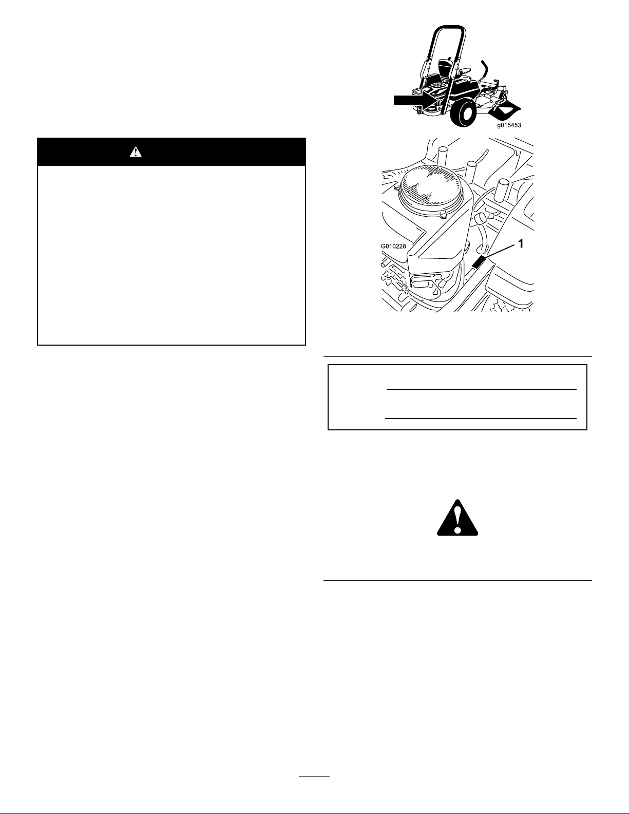
yourproductready.Figure1identiesthelocationofthe
modelandserialnumbersontheproduct.Writethenumbers
inthespaceprovided.
1.Modelandserial-numberlocation
ModelNo.
SerialNo.
Thismanualidentiespotentialhazardsandhassafety
messagesidentiedbythesafetyalertsymbol(Figure2),
whichsignalsahazardthatmaycauseseriousinjuryordeath
ifyoudonotfollowtherecommendedprecautions.
Figure2
1.Safety-alertsymbol
Thismanualuses2otherwordstohighlightinformation.
Importantcallsattentiontospecialmechanicalinformation
andNoteemphasizesgeneralinformationworthyofspecial
attention.
©2015—TheToro®Company
8111LyndaleAvenueSouth
Bloomington,MN55420
Contactusatwww.Toro.com.
2
PrintedintheUSA
AllRightsReserved
Page 3

WARNING
Removingstandardoriginalequipmentpartsand
accessoriesmayalterthewarranty,traction,and
safetyofthemachine.FailuretouseoriginalToro
partscouldcauseseriousinjuryordeath.Making
unauthorizedchangestotheengine,fuelorventing
system,mayviolateEPAandCARBregulations.
Replaceallpartsincluding,butnotlimitedto,tires,
belts,blades,andfuelsystemcomponentswith
originalToroparts.
Formodelswithstatedenginehorsepower,thegross
horsepoweroftheenginewaslaboratoryratedbytheengine
manufacturerinaccordancewithSAEJ1940andratedto
J2723.
Donottamperwiththeenginecontrolsoralterthegovernor
speed;doingsomaycreateanunsafeconditionresultingin
personalinjury.
3
Page 4

Contents
Safety...........................................................................5
SafeOperatingPractices...........................................5
ToroRidingMowerSafety........................................6
Model74846...........................................................7
Model74848...........................................................7
SlopeIndicator.......................................................8
SafetyandInstructionalDecals.................................9
ProductOverview.........................................................14
Controls...............................................................15
Operation....................................................................16
AddingFuel...........................................................16
ThinkSafetyFirst...................................................17
UsingtheRolloverProtectionSystem(ROPS)............18
UnderstandingtheSafety-InterlockSystem................18
TestingtheSafety-InterlockSystem...........................18
CheckingtheEngine-OilLevel.................................19
BreakinginaNewMachine......................................19
OperatingtheParkingBrake....................................19
OperatingtheThrottle............................................19
OperatingtheChoke...............................................19
OperatingtheIgnitionSwitch..................................20
StartingandStoppingtheEngine..............................20
OperatingtheBlade-ControlSwitch(PTO)................21
DrivingtheMachine...............................................21
StoppingtheMachine.............................................23
AdjustingtheHeightofCut.....................................23
AdjustingtheAnti-ScalpRollers...............................24
PositioningtheSeat................................................24
AdjustingtheMotion-ControlLevers........................24
PushingtheMachinebyHand..................................25
Convertingthe48-InchMowertoSide
Discharge..........................................................25
Convertingthe54-InchMowertoSide
Discharge..........................................................27
UsingtheSideDischarge.........................................28
TransportingtheMachine........................................29
LoadingtheMachine..............................................29
OperatingTips......................................................31
Maintenance.................................................................32
RecommendedMaintenanceSchedule(s)......................32
PremaintenanceProcedures........................................33
Service-IntervalChart.............................................33
RaisingtheSeat......................................................33
ReleasingtheMower-DeckCurtain...........................33
Lubrication...............................................................34
GreasingtheBearings.............................................34
EngineMaintenance..................................................34
ServicingtheAirCleaner.........................................34
ServicingtheEngineOil..........................................35
ServicingtheSparkPlug..........................................37
CleaningtheCoolingSystem....................................38
FuelSystemMaintenance...........................................38
ReplacingtheFuelFilter..........................................38
ElectricalSystemMaintenance....................................39
ServicingtheBattery...............................................39
ServicingtheFuses.................................................40
DriveSystemMaintenance.........................................41
CheckingtheTirePressure......................................41
HydraulicSystemMaintenance....................................41
CheckingtheHydraulic-FluidLevel..........................41
ChangingtheHydraulicFilterandFluid.....................41
MowerDeckMaintenance...........................................43
ServicingtheCuttingBlades.....................................43
LevelingtheMowerDeck........................................46
InspectingtheBelts................................................47
ReplacingtheMowerBelt........................................48
RemovingtheMower..............................................48
InstallingtheMowerDeck.......................................49
ReplacingtheGrassDeector..................................49
Cleaning...................................................................51
WashingtheUndersideoftheMower........................51
DisposingofWaste.................................................51
Storage........................................................................52
CleaningandStorage..............................................52
Troubleshooting...........................................................53
Schematics...................................................................55
4
Page 5

Safety
ThefollowinginstructionsarefromtheENstandardEN
ISO5395:2013.
Improperlyusingormaintainingthemachinecanresult
ininjury.Toreducethepotentialforinjury,complywith
thesesafetyinstructionsandalwayspayattentiontothe
safetyalertsymbol,whichmeansCaution,Warning,or
Danger—personalsafetyinstruction.Failuretocomply
withtheinstructionmayresultinpersonalinjuryor
death.
SafeOperatingPractices
Thisproductiscapableofamputatinghandsandfeetand
throwingobjects.Alwaysfollowallsafetyinstructionsto
avoidseriousinjuryordeath.
Training
•Readtheinstructionscarefully .Befamiliarwiththe
controlsandtheproperuseoftheequipment.
•Neverallowchildrenorpeopleunfamiliarwiththese
instructionstousethelawnmower.Localregulationscan
restricttheageoftheoperator.
•Nevermowwhilepeople,especiallychildren,orpetsare
nearby.
•Keepinmindthattheoperatororuserisresponsiblefor
accidentsorhazardsoccurringtootherpeopleortheir
property.
•Donotcarrypassengers.
•Alldriversshouldseekandobtainprofessionaland
practicalinstruction.Suchinstructionshouldemphasize:
–Theneedforcareandconcentrationwhenworking
withride-onmachines;
–Controlofaride-onmachineslidingonaslopewill
notberegainedbytheapplicationofthebrake.The
mainreasonsforlossofcontrolare:
◊Insufcientwheelgrip;
◊Beingdriventoofast;
◊Inadequatebraking;
◊Thetypeofmachineisunsuitableforitstask;
◊Lackofawarenessoftheeffectofground
conditions,especiallyslopes;
◊Incorrecthitchingandloaddistribution.
Preparation
•Whilemowing,alwayswearsubstantial,slip-resistant
footwearandlongtrousers.Tiebackanylonghair.Do
notwearjewelry.
•Thoroughlyinspecttheareawheretheequipmentisto
beusedandremoveallobjectswhichmaybethrownby
themachine.
•Warning-Fuelishighlyammable.
–Storefuelincontainersspecicallydesignedforthis
purpose.
–Refueloutdoorsonlyanddonotsmokewhile
refueling.
–Addfuelbeforestartingtheengine.Neverremove
thecapofthefueltankoraddfuelwhiletheengineis
runningorwhentheengineishot.
–Iffuelisspilled,donotattempttostarttheengine
butmovethemachineawayfromtheareaofspillage
andavoidcreatinganysourceofignitionuntilfuel
vaporshavedissipated.
–Replaceallfueltanksandcontainercapssecurely.
•Replacefaultysilencers.
•Beforeusing,alwaysvisuallyinspecttoseethattheblades,
bladeboltsandcutterassemblyarenotwornordamaged.
Replacewornordamagedbladesandboltsinsetsto
preservebalance.
•Onmulti-bladedmachines,takecareasrotatingoneblade
cancauseotherbladestorotate.
Operation
•Bealert,slowdownandusecautionwhenmakingturns.
Lookbehindandtothesidebeforechangingdirections.
•Donotoperatetheengineinaconnedspacewhere
dangerouscarbonmonoxidefumescancollect.
•Mowonlyindaylightoringoodarticiallight.
•Beforeattemptingtostarttheengine,disengageallblade
attachmentclutchesandshiftintoneutral.
•Donotuseonslopesofmorethan15degrees.
•Rememberthereisnosuchthingasasafeslope.Travel
ongrassslopesrequiresparticularcare.T oguardagainst
overturning:
–donotstoporstartsuddenlywhengoingupor
downhill;
–uselowspeedsonslopesandduringtightturns;
–stayalertforhumpsandhollowsandotherhidden
hazards;
•Usecarewhenpullingloads.
–Useonlyapproveddrawbarhitchpoints.
–Limitloadstothoseyoucansafelycontrol.
–Donotturnsharply.Usecarewhenreversing.
•Watchoutfortrafcwhencrossingornearroadways.
•Stopthebladesrotatingbeforecrossingsurfacesother
thangrass.
•Whenusinganyattachments,neverdirectdischargeof
materialtowardbystandersnorallowanyonenearthe
machinewhileinoperation.
•Neveroperatethemachinewithdamagedguardsor
withoutsafetyprotectivedevicesinplace.
5
Page 6

•Donotchangetheenginegovernorsettingsoroverspeed
theengine.Operatingtheengineatexcessivespeedcan
increasethehazardofpersonalinjury.
•Beforeleavingtheoperator'sposition:
–Disengagethepowertake-offandlowerthe
attachments;
–Changeintoneutralandsettheparkingbrake;
–Shutofftheengineandremovethekey .
•Disengagedrivetoattachments,shutofftheengine,and
disconnectthesparkplugwire(s)orremovetheignition
key.
–Beforeclearingblockagesoruncloggingchute;
–Beforechecking,cleaningorworkingonthe
lawnmower;
–Afterstrikingaforeignobject.Inspectthelawnmower
fordamageandmakerepairsbeforerestartingand
operatingtheequipment;
–Ifthemachinestartstovibrateabnormally(check
immediately).
•Disengagedrivetoattachmentswhentransportingornot
inuse.
•Shutofftheengineanddisengagedrivetoattachment.
–Beforellingthefueltank;
–Beforeremovingthegrasscatcher;
–Beforemakingheightadjustments;unlessan
adjustmentcanbemadefromtheoperator'sposition.
•Reducethethrottlesettingduringenginerun-outand,if
theengineisprovidedwithashut-offvalve,turnthefuel
offattheconclusionofmowing.
•Lightningcancausesevereinjuryordeath.Iflightning
isseenorthunderisheardinthearea,donotoperate
themachine;seekshelter.
MaintenanceandStorage
•Keepallnuts,boltsandscrewstighttobesurethe
equipmentisinsafeworkingcondition.
•Neverstoretheequipmentwithfuelinthetankinsidea
buildingwherefumescanreachanopenameorspark.
•Allowtheenginetocoolbeforestoringinanyenclosure.
•Toreducetherehazard,keeptheengine,silencer,
batterycompartmentandfuelstorageareafreeofgrass,
leaves,orexcessivegrease.
•Checkthegrasscatcherfrequentlyforwearor
deterioration.
•Replacewornordamagedpartsforsafety.
•Ifthefueltankhastobedrained,thisshouldbedone
outdoors.
•Whenmachineistobeparked,storedorleftunattended,
lowerthecuttingmeans.
ToroRidingMowerSafety
ThefollowinglistcontainssafetyinformationspecictoToro
productsorothersafetyinformationthatyoumustknowthat
isnotincludedintheCENstandard.
•Donotoperatetheengineinaconnedspacewhere
dangerouscarbonmonoxideandotherexhaustgasses
cancollect.
•Keephands,feet,hairandlooseclothingawayfrom
attachmentdischargearea,undersideofmowerandany
movingpartswhileengineisrunning.
•Donottouchequipmentorattachmentpartswhichmay
behotfromoperation.Allowtocoolbeforeattempting
tomaintain,adjust,orservice.
•Batteryacidispoisonousandcancauseburns.Avoid
contactwithskin,eyesandclothing.Protectyourface,
eyes,andclothingwhenworkingwithabattery.
•Batterygasescanexplode.Keepcigarettes,sparks,and
amesawayfrombattery.
•UseonlygenuineTororeplacementpartstoensurethat
originalstandardsaremaintained.
•UseonlyToro-approvedattachments.
SlopeOperation
•Donotmowslopesgreaterthan15degrees.
•Donotmowneardrop-offs,ditches,steepbanks,or
water.Wheelsdroppingoveredgescancauserollovers,
whichmayresultinseriousinjury,death,ordrowning.
•Donotmowslopeswhengrassiswet.Slippery
conditionsreducetractionandcouldcauseslidingand
lossofcontrol.
•Donotmakesuddenturnsorrapidspeedchanges.
•Useawalkbehindmowerand/orahandtrimmernear
drop-offs,ditches,steepbanks,orwater.
•Reducespeedanduseextremecautiononslopes.
•Removeormarkobstaclessuchasrocks,treelimbs,etc.
frommowingarea.Tallgrasscanhideobstacles.
•Watchforditches,holes,rocksdips,andrisesthatchange
theoperatingangle,asroughterraincouldoverturnthe
machine.
•Avoidsuddenstartswhenmowinguphillbecausethe
mowermaytipbackwards.
•Beawarethatlossoftractionmayoccurgoingdownhill.
Weighttransfertothefrontwheelsmaycausedrive
wheelstoslipandcauselossofbrakingandsteering.
•Alwaysavoidsuddenstartingorstoppingonaslope.
Iftireslosetraction,disengagethebladesandproceed
slowlyofftheslope.
•Followthemanufacturer'srecommendationsforwheel
weightsorcounterweightstoimprovestability.
•Useextremecarewithgrasscatchersorotherattachments.
Thesecanchangethestabilityofthemachineandcause
lossofcontrol.
6
Page 7

UsingtheRollover-ProtectionSystem
(ROPS)
Model74848
•Keeptherollbarintheraisedandlockedpositionand
usetheseatbeltwhenoperatingthemachine.
•Becertainthattheseatbeltcanbereleasedquicklyin
theeventofanemergency.
•Beawarethereisnorolloverprotectionwhentheroll
barisdown.
•ChecktheareatobemowedandneverfoldtheROPSin
areaswherethereareslopes,dropoffsorwater.
•Lowertherollbaronlywhenabsolutelynecessary.Donot
weartheseatbeltwiththerollbarfoldeddown.
•Checkcarefullyforoverheadclearances(i.e.branches,
doorways,electricalwires)beforedrivingunderany
objectsanddonotcontactthem.
Model74846
SoundPower
Thisunithasaguaranteedsoundpowerlevelof105dBA,
whichincludesanUncertaintyValue(K)of1dBA.
Soundpowerlevelwasdeterminedaccordingtothe
proceduresoutlinedinISO11094.
SoundPower
Thisunithasaguaranteedsoundpowerlevelof105dBA,
whichincludesanUncertaintyValue(K)of1dBA.
Soundpowerlevelwasdeterminedaccordingtothe
proceduresoutlinedinISO11094.
SoundPressure
Thisunithasasoundpressurelevelattheoperator’searof92
dBA,whichincludesanUncertaintyValue(K)of1dBA.
Soundpowerlevelwasdeterminedaccordingtothe
proceduresoutlinedinENISO5395:2013.
Hand-ArmVibration
Measuredvibrationlevelforlefthand=5.8m/s2
Measuredvibrationlevelforrighthand=3.6m/s2
UncertaintyValue(K)=2.3m/s2
Measuredvaluesweredeterminedaccordingtotheprocedures
outlinedinENISO5395:2013.
WholeBodyVibration
SoundPressure
Thisunithasasoundpressurelevelattheoperator’searof92
dBA,whichincludesanUncertaintyValue(K)of1dBA.
Soundpowerlevelwasdeterminedaccordingtothe
proceduresoutlinedinENISO5395:2013.
Hand-ArmVibration
Measuredvibrationlevelforlefthand=4.8m/s2
Measuredvibrationlevelforrighthand=4.4m/s2
UncertaintyValue(K)=2.4m/s2
Measuredvaluesweredeterminedaccordingtotheprocedures
outlinedinENISO5395:2013.
WholeBodyVibration
Measuredvibrationlevel=0.39m/s2
UncertaintyValue(K)=0.19m/s2
Measuredvaluesweredeterminedaccordingtotheprocedures
outlinedinENISO5395:2013.
Measuredvibrationlevel=0.45m/s2
UncertaintyValue(K)=0.22m/s2
Measuredvaluesweredeterminedaccordingtotheprocedures
outlinedinENISO5395:2013.
7
Page 8
SlopeIndicator
G011841
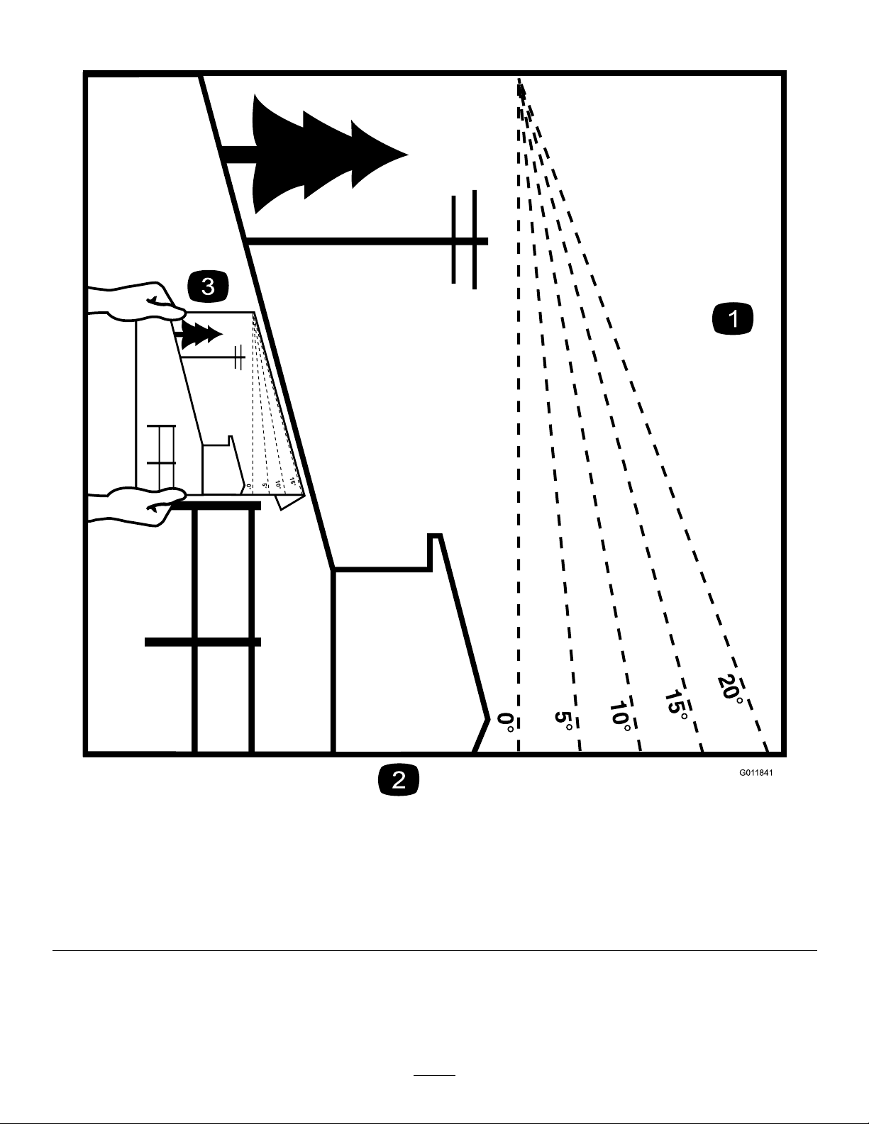
Figure3
Thispagemaybecopiedforpersonaluse.
1.Themaximumslopeyoucansafelyoperatethemachineonis15degrees.Usetheslopecharttodeterminethedegreeofslope
ofhillsbeforeoperating.Donotoperatethismachineonaslopegreaterthan15degrees.Foldalongtheappropriateline
tomatchtherecommendedslope.
2.Alignthisedgewithaverticalsurface,atree,building,fencepole,etc.
3.Exampleofhowtocompareslopewithfoldededge.
8
Page 9
SafetyandInstructionalDecals
Safetydecalsandinstructionsareeasilyvisibletotheoperatorandarelocatednearanyareaofpotential
danger.Replaceanydecalthatisdamagedorlost.
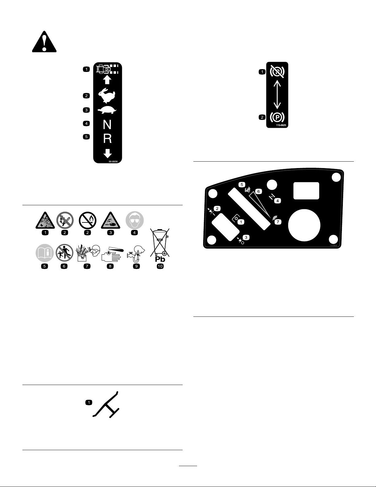
115-9625
99-8936
1.Machinespeed4.NEUTRAL
2.FAST5.REVERSE
3.SLOW
BatterySymbols
Someorallofthesesymbolsareonyourbattery
1.Explosionhazard
2.Nore,opename,or
smoking.
3.Causticliquid/chemical
burnhazard
4.Weareyeprotection.9.Flusheyesimmediately
5.ReadtheOperator's
Manual.
6.Keepbystandersasafe
7.Weareyeprotection;
8.Batteryacidcancause
10.Containslead;donot
distancefromthebattery.
explosivegasescan
causeblindnessandother
injuries.
blindnessorsevereburns.
withwaterandgetmedical
helpfast.
discard.
1.Parking
brake—disengaged
2.Parkingbrake—engaged
115-9632
1.Powertake-off(PTO),
Blade-controlswitchon
somemodels
2.Bladecontrolswitch—ON6.Continuousvariable
3.Bladecontrolswitch—OFF7.SLOW
4.Choke
5.FAST
setting
Manufacturer'sMark
1.Indicatesthebladeisidentiedasapartfromtheoriginal
machinemanufacturer.
9
Page 10
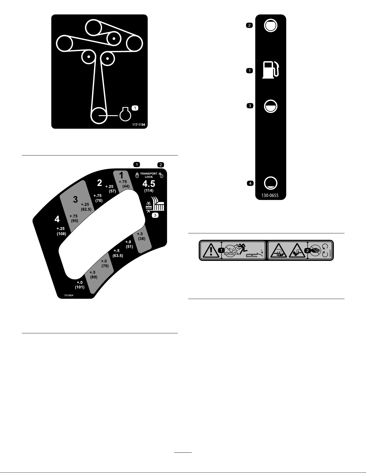
117-1194
1.Engine
130-0655
1.Fueltank
2.Full4.Empty
3.Half
130-0731
1.Warning—thrownobject
hazard;keepthedeector
shieldinplace.
2.Cuttinghazardofhandor
foot,mowerblade—keep
awayfrommovingparts.
130-0654
1.Transport—lock
2.Transport—unlock
3.Heightofcut
10
Page 11
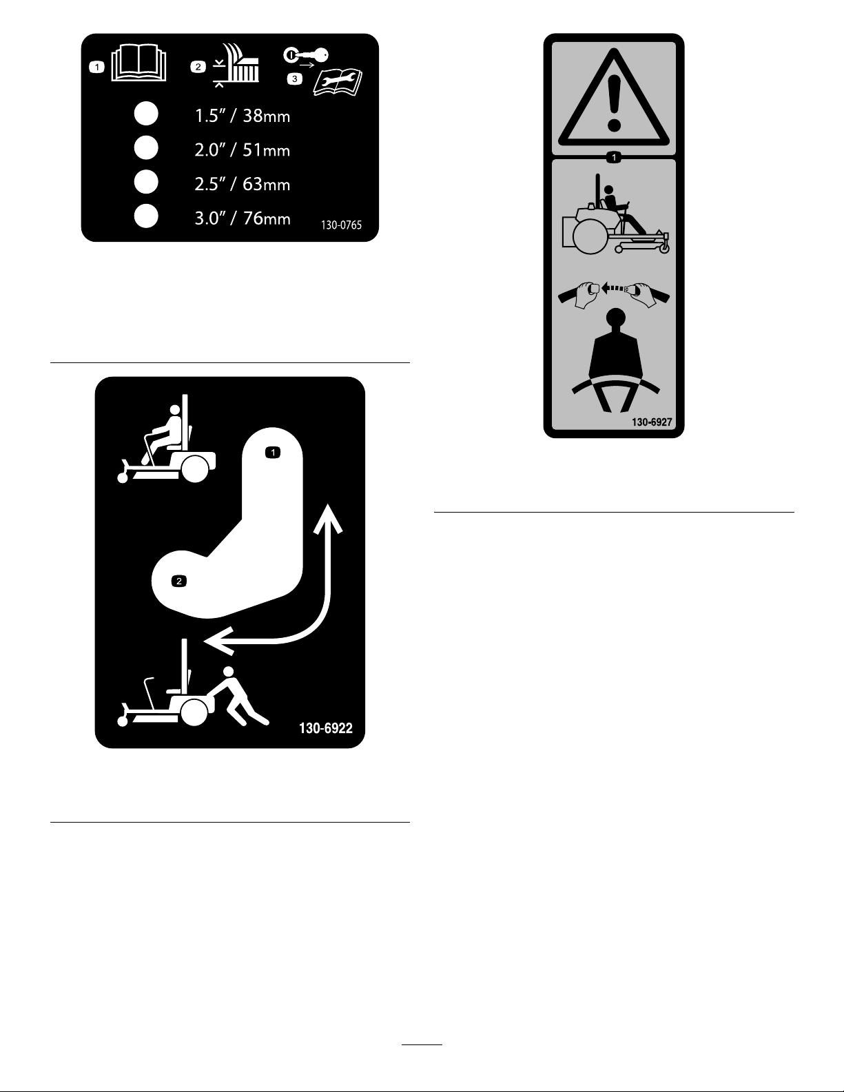
130-0765
1.ReadtheOperator's
Manual.
2.Height-of-cutselection
3.Removethekeyfrom
theignitionandreadthe
Operator'sManualbefore
permorningmaintenance.
130-6927
1.Warning—alwaysusetheROPSandweartheseatbelt
whenseatedintheoperator'sposition.
1.Bypassleverpositionfor
operatingthemachine.
130-6922
2.Bypassleverpositionfor
pushingthemachine.
11
Page 12
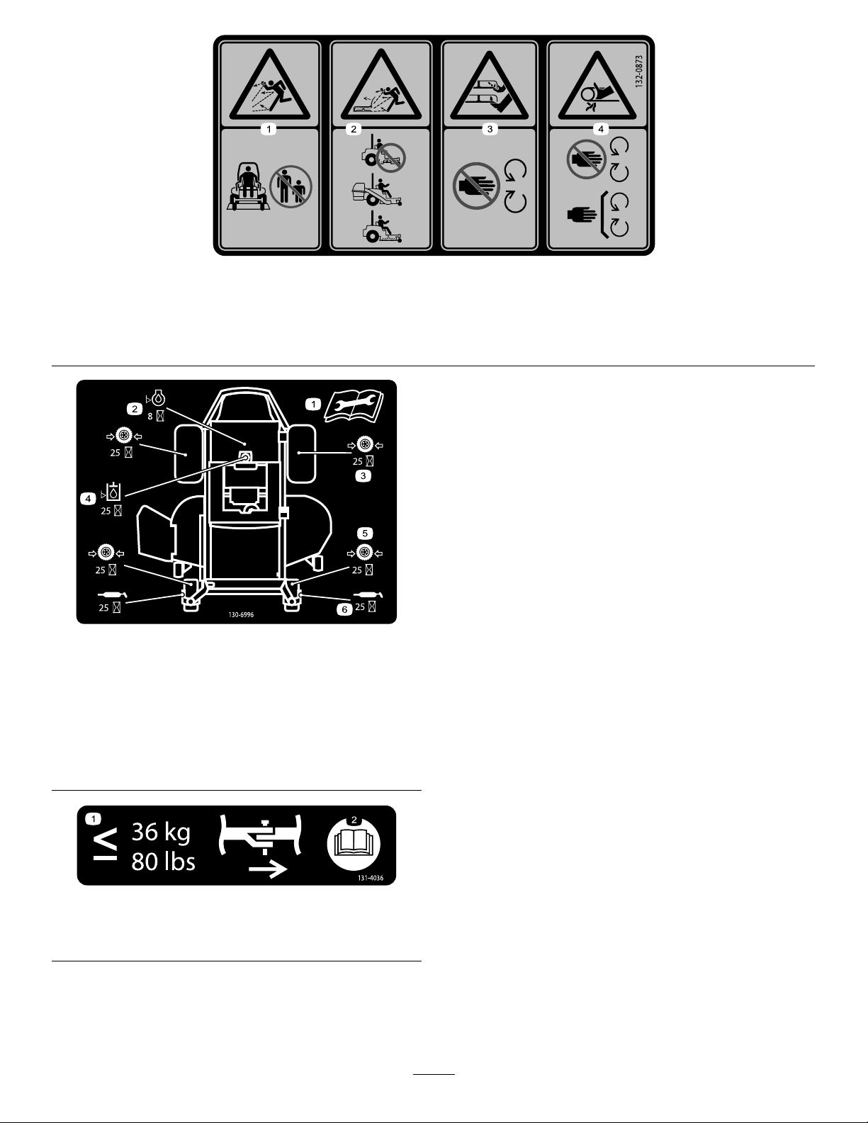
132-0873
1.Thrownobjecthazard—keepbystandersawayfromthe
machine.
2.Thrownobjecthazard,mower—donotoperatethewithout
deector,dischargecover,orgrasscollectionsysteminplace.
130-6996
1.ReadtheOperator's
Manualforinformationon
maintenance.
2.Checktheengineoilevery
8hours
3.Checkthedrivewheeltire
pressureevery25hours
4.Checkthehydraulicoil
every25hours
5.Checkthecasterwheel
tirepressureevery25
hours
6.Lubricatethecasterwheel
every25hours
3.Cutting/dismembermentofhandorfoot—stayawayfrom
movingparts.
4.Entanglementhazard,belt—keepallguardsinplace.
1.Themaximumdrawbar
pullis36kg(80lb).
131-4036
2.ReadtheOperator's
Manual.
12
Page 13

132–0871
1.Warning—readtheOperator’sManual;donotoperatethis
vehicleunlessyouaretrained;wearhearingprotection.
2.Cuttingandpinchinghazard—keephandsandfeetawayfrom
movingparts;keepallguardsandshieldsinplace.
3.Thrownobjecthazard—keepbystandersaway .6.Tippinghazardonslopes—donotuseonslopesnearopen
4.Ramphazard—whenloadingontoatrailer,donotusedual
ramps;onlyuseasingularrampwideenoughforthemachine
andthathasaninclinelessthan15degrees;backupthe
ramp(inreverse)anddriveforwardofftheramp.
5.Bodilyharmhazard—lookbehindyouwhenmowingin
reverse.
water;donotuseonslopesgreaterthan15degrees.
13
Page 14

ProductOverview
g024328
2
5
6
8
9
10
3
4
7
1
Figure4
1.Drivewheel4.Motion-controllevers7.Frontcasterwheel
2.Operatorseat
3.RolloverProtectionSystem
(ROPS)
5.Parkingbrake8.Anti-scalproller
6.Footrest
9.Footpedaldeckliftand
10.Deector
heightofcut
14
Page 15
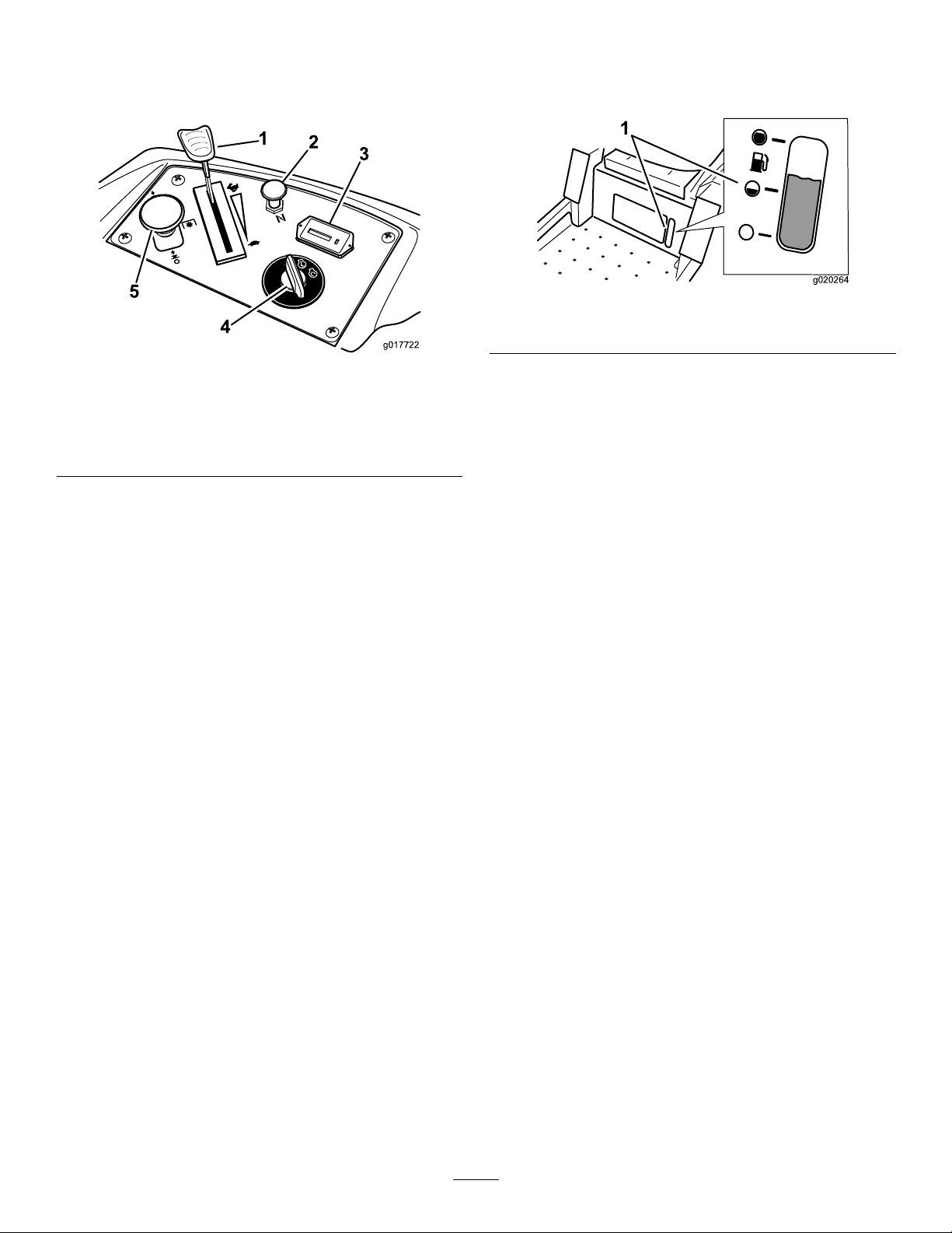
Controls
g017722
1
2
3
4
5
g020264
1
Becomefamiliarwithallthecontrolsbeforeyoustartthe
engineandoperatethemachine(Figure5).
Figure5
FuelGauge
Thefuelwindowlocatedbelowtheoperatorpositioncanbe
usedtoverifythelevelofgasolineinthetank(Figure6).
Figure6
1.Fuel-gaugewindow
1.Throttlecontrol4.Ignitionswitch
2.Choke
3.Hourmeter
5.Blade-controlswitch
(PTO)
IgnitionSwitch
Theignitionswitchhas3positions:START,RUN,andOFF..
ThekeywillturntotheSTARTpositionandmovebackto
theRUNpositionuponrelease.TurningthekeytotheOFF
positionwillshutofftheengine;however,alwaysremovethe
keywhenleavingthemachinetopreventtheenginefrom
accidentallystarting(Figure5).
ThrottleControl
ThethrottlecontrolisvariablebetweentheFASTandSLOW
position.Movingthrottleleverforwardincreasesengine
speedandmovingthrottlelevertothereardecreasesengine
speed.Movingthethrottleforwardintothedetentisfull
throttle(Figure5).
Choke
Usethechoketostartacoldengine.Pullthechokeknobup
toengageit.Pushdownonthechokeknobtodisengageit.
Motion-ControlLevers
Themotion-controlleversarespeed-sensitivecontrolsof
independent-wheelmotors.Movingaleverforwardor
backwardturnsthewheelonthesamesideforwardor
inreverse;wheelspeedisproportionaltotheamountthe
leverismoved.Movethecontrolleversoutwardfromthe
centertotheNEUTRAL-LOCKpositionandexitthemachine
(Figure4).Alwayspositionthemotion-controlleversinto
theNEUTRAL-LOCKpositionwhenyoustopthemachine
orleaveitunattended.
Parking-BrakeLever
Theparking-brakeleverislocatedonleftsideoftheconsole
(Figure4).Thebrakeleverengagesaparkingbrakeonthe
drivewheels.Pulltheleverupandrearwardtoengagethe
brake.Pushtheleverforwardanddowntodisengagethe
brake.
FootPedalDeck-LiftSystem
Thefootpedaldeck-liftsystemallowstheoperatortolower
andraisethedeckfromtheseatedposition.Theoperatorcan
usethefootpedaltoliftthedeckbrieytoavoidobstacles
orlockthedeckinthehighestheightofcutortransport
position(Figure4).
Height-of-CutLever
BladeControlSwitch(PowerTakeoff)
Theblade-controlswitchengagesanddisengagespowerto
themowerblades(Figure5).
HourMeter
Thehourmeterrecordsthenumberofhourstheblades
operate.Itoperateswhentheblade-controlswitch(PTO)is
engaged.Usethesetimesforschedulingregularmaintenance
(Figure5).
Theheight-of-cutleverworkswiththefootpedaltolockthe
deckinaspeciccuttingheight.Onlyadjusttheheightofcut
whilemachineisnotmoving(Figure4).
Attachments/Accessories
AselectionofToroapprovedattachmentsandaccessoriesis
availableforusewiththemachinetoenhanceandexpand
itscapabilities.ContactyourAuthorizedServiceDealeror
Distributororgotowww .Toro.comforalistofallapproved
attachmentsandaccessories.
15
Page 16

Operation
Note:Determinetheleftandrightsidesofthemachine
fromthenormaloperatingposition.
AddingFuel
•Forbestresults,useonlyclean,fresh,unleadedgasoline
withanoctaneratingof87orhigher((R+M)/2rating
method).
•Oxygenatedfuelwithupto10%ethanolor15%MTBE
byvolumeisacceptable.
•Donotuseethanolblendsofgasoline(suchasE15
orE85)withmorethan10%ethanolbyvolume.
Performanceproblemsand/orenginedamagemayresult
whichmaynotbecoveredunderwarranty.
•Donotusegasolinecontainingmethanol.
•Donotstorefueleitherinthefueltankorfuelcontainers
overthewinterunlessafuelstabilizerisused.
•Donotaddoiltogasoline.
DANGER
Incertainconditionsduringfueling,static
electricitycanbereleasedcausingasparkwhich
canignitethegasolinevapors.Areorexplosion
fromgasolinecanburnyouandothersandcan
damageproperty.
•Alwaysplacegasolinecontainersontheground
awayfromyourvehiclebeforelling .
•Donotllgasolinecontainersinsideavehicleor
onatruckortrailerbedbecauseinteriorcarpets
orplastictruckbedlinersmayinsulatethe
containerandslowthelossofanystaticcharge.
WARNING
Gasolineisharmfulorfatalifswallowed.Long-term
exposuretovaporscancauseseriousinjuryand
illness.
•Avoidprolongedbreathingofvapors.
•Keepfaceawayfromnozzleandgastankor
conditioneropening.
•Keepgasawayfromeyesandskin.
DANGER
Incertainconditions,gasolineisextremely
ammableandhighlyexplosive.Areorexplosion
fromgasolinecanburnyouandothersandcan
damageproperty.
•Fillthefueltankoutdoors,inanopenarea,
whentheengineiscold.Wipeupanygasoline
thatspills.
•Neverllthefueltankinsideanenclosedtrailer.
•Donotllthefueltankcompletelyfull.Add
gasolinetothefueltankuntilthelevelis6to13
mm(1/4to1/2inch)belowthebottomofthe
llerneck.Thisemptyspaceinthetankallows
gasolinetoexpand.
•Neversmokewhenhandlinggasoline,andstay
awayfromanopenameorwheregasoline
fumesmaybeignitedbyaspark.
•Storegasolineinanapprovedcontainerand
keepitoutofthereachofchildren.Neverbuy
morethana30-daysupplyofgasoline.
•Donotoperatewithoutentireexhaustsystemin
placeandinproperworkingcondition.
•Whenpractical,removegas-poweredequipment
fromthetruckortrailerandrefueltheequipment
withitswheelsontheground.
•Ifthisisnotpossible,thenrefuelsuch
equipmentonatruckortrailerfromaportable
container,ratherthanfromagasolinedispenser
nozzle.
•Ifagasolinedispensernozzlemustbeused,
keepthenozzleincontactwiththerimofthe
fueltankorcontaineropeningatalltimesuntil
fuelingiscomplete.
UsingStabilizer/Conditioner
Useafuelstabilizer/conditionerinthemachinetoprovide
thefollowingbenets:
•Keepsgasolinefreshduringstorageof90daysorless.
Forlongerstorageitisrecommendedthatthefueltank
bedrained.
•Cleanstheenginewhileitruns
•Eliminatesgum-likevarnishbuildupinthefuelsystem,
whichcauseshardstarting
Important:Donotusefueladditivescontaining
methanolorethanol.
Addthecorrectamountofgasstabilizer/conditionertothe
gas.
Note:Afuelstabilizer/conditionerismosteffectivewhen
mixedwithfreshgasoline.Tominimizethechanceofvarnish
depositsinthefuelsystem,usefuelstabilizeratalltimes.
16
Page 17
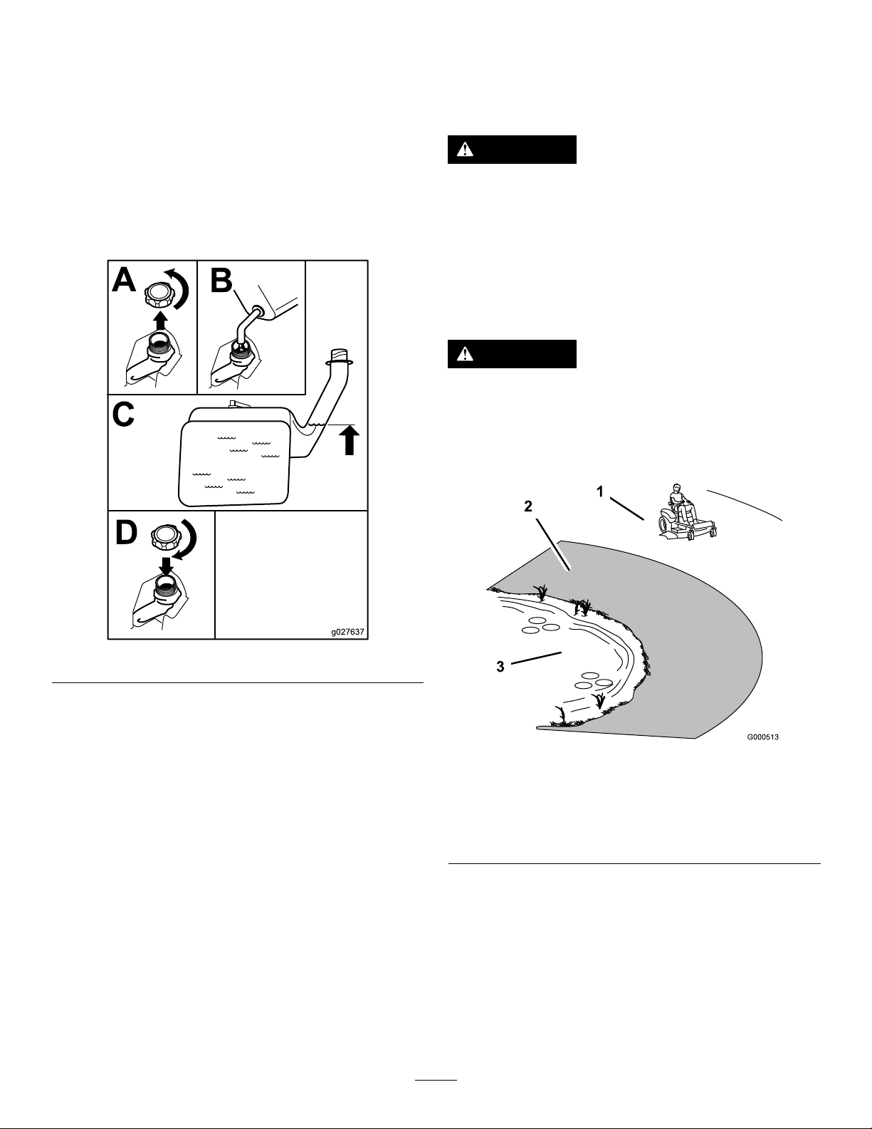
FillingtheFuelTank
B
A
C
D
g027637
Shutofftheengineandmovethemotioncontrolstothe
PARKposition.
Important:Donotoverllfueltank.Fillthefueltank
tothebottomofthellerneck.Theemptyspaceinthe
tankallowsthefueltoexpand.Overllingmayresultin
fuelleakageordamagetotheengineoremissionsystem.
1.Cleanaroundthefuel-tankcapandremovethecap.
ThinkSafetyFirst
Pleasereadallsafetyinstructionsandsymbolsinthesafety
section.Knowingthisinformationcouldhelpyouor
bystandersavoidinjury.
DANGER
Operatingthemachineonwetgrassorsteepslopes
cancauseslidingandlossofcontrol.
2.Slowlyaddregular,unleadedgasolineuntilthefuel
reachesthebaseofthellerneckFigure7.
•Donotoperateonslopesgreaterthan15degrees.
•Reducespeedanduseextremecautionon
slopes.
•Donotoperatethemachinenearwater.
DANGER
Wheelsdroppingoveredgescancauserollovers,
whichmayresultinseriousinjury,death,or
drowning.
Donotoperatethemachineneardrop-offs.
Figure7
3.Installthefuel-tankcapsecurelyandtightenuntilit
clicks.
Note:Wipeupanygasolinethatmayhavespilled.
1.Safezone—usethe
machinehere.
2.Useawalk-behindmower
and/orhandtrimmernear
drop-offsandwater.
Figure8
3.Water
17
Page 18
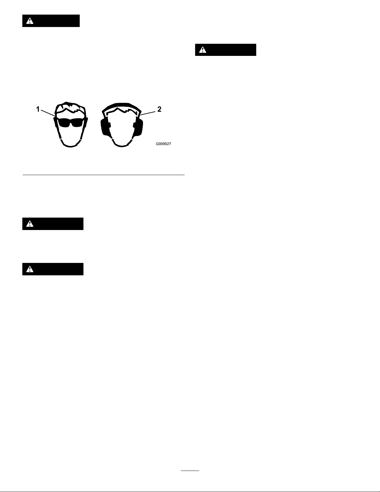
CAUTION
G009027
1
2
Understandingthe
Thismachineproducessoundlevelsinexcessof
85dBAattheoperator’searandcancausehearing
lossthroughextendedperiodsofexposure.
Wearhearingprotectionwhenoperatingthis
machine.
Theuseofprotectiveequipmentforeyes,ears,hands,feet,
andheadisrecommended.
Figure9
1.Weareyeprotection.2.Wearhearingprotection.
UsingtheRolloverProtection System(ROPS)
Safety-InterlockSystem
WARNING
Ifthesafety-interlockswitchesaredisconnectedor
damaged,themachinecouldoperateunexpectedly,
causingpersonalinjury.
•Donottamperwiththeinterlockswitches.
•Checktheoperationoftheinterlockswitches
dailyandreplaceanydamagedswitchesbefore
operatingthemachine.
Thesafety-interlocksystemisdesignedtopreventtheengine
fromstartingunless:
•Thebladesaredisengaged.
•Themotion-controlleversareinthePARKposition.
Thesafety-interlocksystemalsoisdesignedtoshutoffthe
enginewheneverthecontrolleversareoutofthePARK
positionandyourisefromtheseat.
TestingtheSafety-Interlock
WARNING
Toavoidinjuryordeathfromrollover:keeptheroll
barinstalledandusetheseatbelt.
WARNING
Thereisnorolloverprotectionwhentherollbaris
removed.
•Driveslowlyandcarefully.
•Checkcarefullyforoverheadclearances(i.e.
branches,doorways,electricalwires)before
drivingunderanyobjectsanddonotcontact
them.
System
Testthesafety-interlocksystembeforeyouusethemachine
eachtime.Ifthesafetysystemdoesnotoperateasdescribed
below,haveanAuthorizedServiceDealerrepairthesafety
systemimmediately.
1.Whilesittingontheseat,withthecontrolleversinthe
PARKposition,andmovetheblade-controlswitchto
theONposition.Trystartingtheengine;theengine
shouldnotcrank.
2.Whilesittingontheseat,movetheblade-controlswitch
totheOFFposition.Moveeithermotioncontrol
levertothecenter,unlockedposition.Trystartingthe
engine;theengineshouldnotcrank.Repeatwiththe
othermotion-controllever.
3.Whilesittingontheseat,movethebladecontrolswitch
totheOFFposition,andlockthemotion-controllevers
inthePARKposition.Starttheengine.Whilethe
engineisrunning,engagetheblade-controlswitch,and
riseslightlyfromtheseat;theengineshouldstop.
4.Whilesittingontheseat,movetheblade-controlswitch
totheOFFposition,andlockthemotion-controllevers
inthePARKposition.Starttheengine.Whilethe
engineisrunning,movethemotion-controlleversto
thecenter,unlockedposition,engagetheblade-control
switch,andriseslightlyfromtheseat;theengine
shouldstop.
18
Page 19

CheckingtheEngine-OilLevel
B
A
g027638
B
A
g027639
G008946
G008959
1
2
OperatingtheThrottle
Beforeyoustarttheengineandusethemachine,check
theoillevelintheenginecrankcase;refertoCheckingthe
Engine-OilLevel(page35).
BreakinginaNewMachine
Newenginestaketimetodevelopfullpower.Mowerdecks
anddrivesystemshavehigherfrictionwhennew,placing
additionalloadontheengine.Allow40to50hoursof
break-intimefornewmachinestodevelopfullpowerand
bestperformance.
OperatingtheParkingBrake
Alwayssettheparkingbrakewhenyoustopthemachineor
leaveitunattended.
SettingtheParkingBrake
ThethrottlecontrolcanbemovedbetweentheSLOWand
FASTpositions(Figure12).
AlwaysusetheFASTpositionwhenturningonthemower
deckwiththeblade-controlswitch(PTO).
Figure12
OperatingtheChoke
Usethechoketostartacoldengine.
1.Iftheengineiscold,usethechoketostarttheengine.
2.Pulluponthechokeknobtoengagethechokebefore
usingtheignitionswitch(Figure13).
3.Pushdownonthechoketodisengagethechokeafter
theenginestarts(Figure13).
Figure10
ReleasingtheParkingBrake
Figure11
Figure13
1.ONposition2.OFFposition
19
Page 20

OperatingtheIgnitionSwitch
START
RUN
STOP
G008947
g027640
B
A
D
C
F
E
S
T
A
R
T
R
U
N
S
T
O
P
H
G
1.TurntheignitionkeytotheSTARTposition(Figure14).
Note:Whentheenginesstarts,releasethekey.
Note:Additionalstartingcyclesmayberequired
whenstartingtheengineforthersttimeafterthefuel
systemhasbeenwithoutfuelcompletely.
Figure14
2.TurntheignitionkeytotheSTOPposition.
StartingandStoppingthe Engine
StartingtheEngine
StarttheengineasshowninFigure15.
Note:Awarmorhotenginemaynotrequirechoking.
Important:Donotengagestarterformorethan5
secondsatatime.Iftheenginefailstostartallowa15
secondcool-downperiodbetweenattempts.Failureto
followtheseinstructionscanburnoutthestartermotor.
Note:Ifthefuelsystemwasdepletedoffuel—addfuelto
themachineanduseadditionalstartingcycleswhenstarting
theengine.
Figure15
StoppingtheEngine
CAUTION
Injurycanoccurifchildrenorbystandersmove
orattempttooperatethemachinewhileitis
unattended.
Alwaysremovetheignitionkeyandsettheparking
brakewhenleavingthemachineunattended,even
ifjustforafewminutes.
20
Page 21

BA
DC
E
S
T
A
R
T
R
U
N
S
T
O
P
00:60 Sec
g027641
Figure16
G008945
G009174
DisengagingtheBlade-ControlSwitch
(PTO)
Figure18
DrivingtheMachine
Thethrottlecontrolregulatestheenginespeedasmeasured
inrpm(revolutionsperminute).Placethethrottlecontrolin
theFASTpositionforbestperformance.Alwaysoperatein
thefull-throttlepositionwhenmowing.
CAUTION
Machinecanspinveryrapidly.Operatormaylose
controlofmachineandcausepersonalinjuryor
damagetomachine.
•Usecautionwhenmakingturns.
OperatingtheBlade-Control Switch(PTO)
Theblade-controlswitch(PTO)startsandstopsthemower
bladesandanypoweredattachments.
EngagingtheBlade-ControlSwitch
(PTO)
Engagetheblade-controlswitch(PTO)withthethrottle
positionatFAST.
Note:Engagingtheblade-controlswitch(PTO)withthe
throttlepositionathalforlesswillcauseexcessivewearto
thedrivebelts.
•Slowthemachinedownbeforemakingsharp
turns.
UsingtheMotion-ControlLevers
Usethemotion-controlleversasshowninFigure19.
Figure17
21
Page 22

Figure19
G008952
G008953
Figure20
1.Motion-control
lever—NEUTRAL-LOCK
position
2.Center,unlockedposition5.Frontofthemachine
3.Forward
4.Backward
DrivingForward
Note:Theenginekillsifthetraction-controlleversare
movedwiththeparkingbrakeengaged.
1.Releasetheparkingbrake.
2.Movetheleverstothecenter,unlockedposition.
3.Tomoveforward,slowlypushthemotion-control
leversforward(Figure20).
DrivingBackward
Note:Alwaysusecautionwhenbackingupandturning.
1.Movetheleverstothecenter,unlockedposition.
2.Togobackward,slowlypullthemotion-controllevers
rearward(Figure21).
Figure21
22
Page 23

StoppingtheMachine
g024409
WARNING
Childrenorbystandersmaybeinjuredifthey
moveorattempttooperatethemachinewhileitis
unattended.
Alwaysremovetheignitionkeyandmovethe
motion-controlleversoutwardtothePARKposition
whenleavingthemachineunattended,evenifjust
forafewminutes.
Tostopthemachine,movethetraction-controlleversto
theNEUTRALpositionandmovetothelockedposition,
disengagetheblade-controlswitch(PTO),andturnthe
ignitionkeytotheOFFposition.
Settheparkingbrakewhenyouleavethemachine.Remember
toremovethekeyfromtheignitionswitch.
AdjustingtheHeightofCut
Themachineisequippedwithafootpedaldeck-liftsystem.
Theoperatorcanusethefootpedaltoliftthedeckbrieyto
avoidobstaclesorlockthedeckinthehighestheightofcut
ortransportposition.Theoperatorcanusetheheight-of-cut
leverwiththefootpedaltolockthedeckinaspeciccutting
height.
Figure22
TransportLockPosition
AdjustingtheHeightofCut
Theheightofcutcanbeadjustedfrom38to114mm(1-1/2
to4-1/2inch)in6mm(1/4inch)incrementsbyrelocating
theheight-of-cutpinintodifferentholelocations.
UsingtheFootPedalDeck-LiftSystem
•Pressthepedaldowntoraisethedeck;continuetopress
thepedaluntilthedeckislockedinthetransportposition
(Figure22).
•Pushonthedeck-liftpedalwithyourfootandpullthe
transportlockhandlerearwardtodisengagethetransport
lock(Figure22).
1.Pushonthedeck-liftpedalwithyourfootandraise
themowerdecktothetransport-lockposition(also
the114mm(4-1/2inch)cuttingheightposition)as
showninFigure23.
2.Toadjust,removethepinfromtheheight-of-cut
bracket(Figure23).
3.Selectaholeintheheight-of-cutsystemcorresponding
tothedesiredheightofcutandinsertthepin(Figure
23).
4.Pushonthedeck-liftpedalwithyourfootandpull
thehandlerearwardtodisengagethetransportlock
(Figure22).
5.Lowerthedeckslowlyuntilthelevermakescontact
withthepin.
23
Page 24

g024410
1
2
3
4
Figure23
g024312
1
2 3 4
5
g027252
B
A
1.Deck-liftpedal3.Height-of-cutpositions
2.Handle4.Pin
AdjustingtheAnti-Scalp
4.Aligntheboltandanti-scalprollerintheholeofthe
bracketthatmatchedtheclosestheight-of-cutposition
(Figure24).
5.Inserttheboltintothebracketholeandsecurethebolt
andanti-scalprollerwiththeangenut(Figure24).
PositioningtheSeat
Theseatcanmoveforwardandbackward(Figure25).
Positiontheseatwhereyouhavethebestcontrolofthe
machineandaremostcomfortable.
Rollers
Wheneveryouchangetheheightofcut,itisrecommendedto
adjusttheheightoftheanti-scalprollers.
1.Disengagetheblade-controlswitch(PTO),movethe
motion-controlleverstotheNEUTRAL-LOCKposition,
andsettheparkingbrake.
2.Shutofftheengine,removethekey,andwaitforall
movingpartstostopbeforeleavingtheoperating
position.
3.Removetheangenut,anti-scalproller,andboltfrom
thebracket(Figure24).
Note:Keeptheboltandanti-scalprollertogether
whenremoving.
Figure25
AdjustingtheMotion-Control Levers
AdjustingtheHeight
Note:Repeattheadjustmentfortheoppositecontrollever.
Themotion-controlleverscanbeadjustedhigherorlowerfor
maximumoperatorcomfort(Figure26).
1.Flangenut4.Bushing
2.Spacer
3.Anti-scalproller
Figure24
5.Bolt
Figure26
24
Page 25

AdjustingtheTilt
BA
DC
g027642
1
1
2
3
G012841
Themotion-controlleverscanbetiltedforwardorrearward
formaximumoperatorcomfort.
1.Loosentheupperboltholdingthecontrollevertothe
control-armshaft.
2.Loosenthelowerboltjustenoughtopivotthecontrol
leverforwardorrearward.
3.Tightenbothboltstosecurethecontrolinthenew
position.
4.Repeattheadjustmentfortheoppositecontrollever.
PushingtheMachinebyHand
Important:Alwayspushthemachinebyhand.Never
towthemachinebecausedamagemayoccur.
1.Parkthemachineonalevelsurfaceanddisengagethe
bladecontrolswitch.
Convertingthe48-InchMower toSideDischarge
Themowerdeckandmowerbladesshippedwiththismachine
weredesignedforoptimummulchingandside-discharge
performance.
Installthefastenersintothesameholesinthedeckthatthey
wereoriginallyremovedfrom.Thisensurenoholesareleft
openwhenthedeckisoperated.
DANGER
Openholesinthemowerexposeyouandothersto
throwndebris.Debristhrownoutofholesinthe
mowercancauseinjury.
•Neveroperatethemowerwithouthardware
mountedinallholesinthemower.
•Installhardwareinmountingholeswhenthe
bafeisremoved.
2.Movethemotioncontrolleversoutwardtoneutrallock
position,shutofftheengine,removethekey,andwait
forallmovingpartstostopbeforeleavingtheoperating
position.Makesuretheparkingbrakeisdisengaged.
3.DothisprocedureoneachsideofthemachineFigure
27.
RemovingtheMulchingBafe
1.Parkthemachineonalevelsurfaceanddisengagethe
blade-controlswitch.
2.Movethemotion-controlleversoutwardtothe
NEUTRAL-LOCKposition,settheparkingbrake,shut
offtheengine,removethekey,andwaitforallmoving
partstostopbeforeleavingtheoperatingposition.
3.Removethemower;refertoRemovingtheMower
(page48).
4.Turnthemowerupsidedown.
5.Removethe2locknuts(5/16inch)securedtothe
weldedpostsoftheleftbafeonthetopofthemower
deckatthecenterandleftofcenterpositions(Figure
28).
Figure27
4.Movethebypasstothepositionforoperatingthe
machine(Figure27)toengagethewheelmotors.
Figure28
1.Locknut(5/16inch)3.Leftbafe
2.Carriagebolt(5/16x3/4
inch)
6.Removethecarriageboltandlocknutonthesidewall
ofthemowerdecksecuringtheleftbafetothedeck.
25
Page 26

7.Removetheleftbafefromthemowerdeckasshown
G012806
1
2
3
4
3
2
1
2
3
G012805
G012800
1
2
3
4
inFigure28.
8.Removethecarriagebolt(5/16x3/4inch)andlocknut
(5/16inch)ontherearwallofthemowerdecksecuring
thebafetothedeck(Figure29).
Figure29
Figure30
1.Locknut(5/16inch)3.Weldedposts,rightbafe
2.Rightbafe
11.Locatethecutoffbafeintheloosepartsbagand
removethefastenersattherearholesofthedischarge
plate(Figure31).
1.Bafeguard3.Carriagebolt(5/16x3/4
2.Locknut(5/16inch)4.Rightbafe
inch)
9.Locatethebafeguardatthefrontedgeoftheside
dischargeopeningandremovethefastenerssecuring
thebafeguardandtherightbafetothemowerdeck
(Figure29).
Note:Removethebafeguardandretainallfasteners.
10.Removethe2locknuts(5/16inch)tosecuringthe
weldedpostsoftherightbafetothetopofthemower
deckatcenterandrightofcenterpositions(Figure30).
Note:Removetherightbafefromthemowerdeck.
Figure31
1.Carriagebolt,existing3.Cutoffbafe,shipped
2.Rearholesinthe
dischargeplate
loose
4.Locknut,existing
12.Installthebafeatthesidedischargeopeningonthe
mowerdeck.
13.Usethefastenersremovedtosecurethecutoffbafe
tothedeck.
14.Installthemower;refertoInstallingtheMowerDeck
(page49).
26
Page 27

Convertingthe54-InchMower
G011149
1
1
2
3
4
G010712
1
2
4
3
5
6
7
toSideDischarge
Installthefastenersintothesameholesinthedeckasthey
wereoriginallyremovedfrom.Thisensuresthatnoholesare
leftopenwhenthedeckisoperated.
DANGER
Openholesinthemowerexposeyouandothersto
throwndebris.Debristhrownoutofholesinthe
mowercancauseinjury.
•Neveroperatethemowerwithouthardware
mountedinallholesinthemower.
•Installhardwareinmountingholeswhenthe
bafeisremoved.
RemovingtheMulchingBafe
1.Parkthemachineonalevelsurfaceanddisengagethe
blade-controlswitch.
2.Movethemotion-controlleversoutwardtothe
NEUTRAL-LOCKposition,settheparkingbrake,shut
offtheengine,removethekey,andwaitforallmoving
partstostopbeforeleavingtheoperatingposition.
3.Removethemower;refertoRemovingtheMower
(page48).
4.Turnthemowerupsidedown.
5.Removethe3locknuts(5/16inch)securedtothe
weldedpostsoftheleftbafeonthetopofthemower
deckatthecenter,leftofcenterandleftpositions
(Figure32).
8.Locatethe2boltsinloosepartsandusetheexisting
locknutsandinstallthesefastenersintotheholes
showninFigure32onthemowerdecktoprevent
yingdebris.
Note:Installtheboltup,throughtheundersideof
thedeckanduseanexistinglocknuttosecurefrom
thetopside.
WARNING
Openholesinthemowerexposeyouand
otherstothrowndebriswhichcancause
severeinjury.
•Neveroperatethemowerwithouthardware
mountedinallholesinthemowerhousing.
•Installthehardwareinthemountingholes
whenyouremovethemulchingbafe.
9.Removethecarriagebolt(5/16x3/4inch)andlocknut
(5/16inch)ontherearwallofthemowerdecksecuring
thebafetothedeck(Figure33).
Figure32
1.Locknut(5/16inch)3.Leftbafe
2.Carriagebolt(5/16x3/4
inch)
4.Installfastenershere
6.Removethecarriageboltandlocknutonthesidewall
ofthemowerdecksecuringtheleftbafetothedeck
(Figure32).
7.Removetheleftbafefromthemowerdeck(Figure
32).
Figure33
1.Carriagebolt(5/16x3/4
inch)
2.Locknut,frontofdischarge
plate(reinstallafterbafe
isremoved)
3.Locknut,forwardholein
deck(reinstallafterbafe
isremoved)
4.Bafeguard,54inch
decks
10.Locatethebafeguardatthefrontedgeoftheside
dischargeopening(Figure33).
5.Hex-headbolt,forward
holeindeck(reinstallafter
bafeisremoved)
6.Carriagebolts,frontof
dischargeplate(reinstall
afterbafeisremoved)
7.Locknut(5/16inch)
11.Removethefastenerssecuringthebafeguardandthe
rightbafetothemowerdeck(Figure33).
Note:Removethebafeguardandretainallfasteners.
27
Page 28

12.Removethe2locknuts(5/16inch)securingthewelded
G010704
1
2
3
postsoftherightbafetothetopofthemowerdeck
atcenterandrightofcenterpositions(Figure34).
16.Usethefastenersremovedtosecurethecutoffbafe
tothedeck.
17.Installthemower;refertoInstallingtheMowerDeck
(page49).
UsingtheSideDischarge
Themowerhasahingedgrassdeectorthatdisperses
clippingstothesideanddowntowardtheturf.
DANGER
Withoutagrassdeector,dischargecover,or
completegrasscatcherassemblymountedin
place,youandothersareexposedtobladecontact
andthrowndebris.Contactwithrotatingmower
blade(s)andthrowndebriswillcauseinjuryor
death.
Figure34
1.Locknut(5/16inch)3.Weldedposts,rightbafe
2.Rightbafe4.Carriagebolt
13.Removethecarriageboltandlocknutsecuringtheright
bafetothetopofthemowerdeckandremovethe
rightbafefromthemowerdeck(Figure34).
14.Installthefastenersremovedpreviouslyatthefront
holesinthedischargeplateandforwardholeinthe
deck(Figure33).
15.Locatethecutoffbafeintheloosepartsbag,remove
thefastenersattherearholesofthedischargeplate,
andinstallthebafeattheside-dischargeopeningon
themowerdeck(Figure35).
•Neverremovethegrassdeectorfromthemower
becausethegrassdeectorroutesmaterialdown
towardtheturf.Ifthegrassdeectorisever
damaged,replaceitimmediately .
•Neverputyourhandsorfeetunderthemower.
•Nevertrytoclearthedischargeareaormower
bladesunlessyoumovetheblade-controlswitch
(PTO)totheOFFposition,rotatetheignition
keytotheOFFposition,andremovethekey.
•Makesurethatthegrassdeectorisinthedown
position.
Figure35
1.Carriagebolt3.Cutoffbafe
2.Rearholesinthe
dischargeplate
4.Locknut
28
Page 29

TransportingtheMachine
g028043
Useaheavy-dutytrailerortrucktotransportthemachine.
Ensurethatthetrailerortruckhasallnecessarybrakes,
lighting,andmarkingasrequiredbylaw .Pleasecarefullyread
allthesafetyinstructions.Knowingthisinformationcould
helpyou,yourfamily,pets,orbystandersavoidinjury.
WARNING
Drivingonthestreetorroadwaywithout
turnsignals,lights,reectivemarkings,ora
slow-moving-vehicleemblemisdangerousandcan
leadtoaccidents,causingpersonalinjury.
Donotdrivethemachineonapublicstreetor
roadway.
1.Ifyouareusingatrailer,connectittothetowing
vehicleandconnectthesafetychains.
2.Ifapplicable,connectthetrailerbrakes.
3.Loadthemachineontothetrailerortruck.
4.Shutofftheengine,removethekey ,setthebrake,and
closethefuelvalve.
5.Tiedownthemachinenearthefrontcasterwheelsand
therearbumper(Figure36).
Important:Donotusenarrowindividualrampsfor
eachsideofthemachine.
Ensuretherampislongenoughsothattheanglewiththe
grounddoesnotexceed15degrees(Figure38).Onat
ground,thisrequiresaramptobeatleast4timesaslongas
theheightofthetrailerortruckbedtotheground.Asteeper
anglemaycausemowercomponentstogetcaughtastheunit
movesfromtheramptothetrailerortruck.Steeperangles
mayalsocausethemachinetotiporlosecontrol.Ifloading
onornearaslope,positionthetrailerortrucksothatitis
onthedownsideoftheslopeandtherampextendsupthe
slope.Thiswillminimizetherampangle.
WARNING
Loadingamachineontoatrailerortruckincreases
thepossibilityoftip-overandcouldcauseserious
injuryordeath.
•Useextremecautionwhenoperatingamachine
onaramp.
•Useonlyafull-widthramp;donotuseindividual
rampsforeachsideofthemachine.
•Donotexceeda15-degreeanglebetweenthe
rampandthegroundorbetweentherampand
thetrailerortruck.
Figure36
LoadingtheMachine
Useextremecautionwhenloadingorunloadingmachines
ontoatraileroratruck.Useafull-widthrampthatiswider
thanthemachineforthisprocedure.Backthemachineupthe
rampanddriveitforwarddowntheramp(Figure37).
•Ensurethelengthoframpisatleast4timesas
longastheheightofthetrailerortruckbedto
theground.Thiswillensurethatrampangle
doesnotexceed15degreesonatground.
•Backuprampsanddriveforwarddownramps.
•Avoidsuddenaccelerationordecelerationwhile
drivingthemachineonarampasthiscould
causealossofcontroloratip-oversituation.
1.Backthemachineupthe
ramp.
Figure37
2.Drivethemachineforward
downtheramp.
29
Page 30

g027996
5
1
2
6
Figure38
1.Full-widthrampinstowed
position
2.Sideviewoffull-width
rampinloadingposition
3.Notgreaterthan
15degrees
4.Rampisatleast4times
aslongastheheightof
thetrailerortruckbedto
theground
5.H=heightofthetraileror
truckbedtotheground
6.Trailer
30
Page 31

OperatingTips
UsingtheFastThrottleSetting
cuttingheighthigherthanusualandcutthegrassatthis
setting.Thencutthegrassagainusingthelower,normal
setting.
Forbestmowingandmaximumaircirculation,operatethe
engineattheFASTposition.Airisrequiredtothoroughlycut
grassclippings,sodonotsettheheight-of-cutsolowasto
totallysurroundthemowerinuncutgrass.Alwaystrytohave
1sideofthemowerfreefromuncutgrass,whichallowsair
tobedrawnintothemower.
CuttingaLawnfortheFirstTime
Cutgrassslightlylongerthannormaltoensurethatthe
cuttingheightofthemowerdoesnotscalpanyuneven
ground.However,thecuttingheightusedinthepastis
generallythebestonetouse.Whencuttinggrasslongerthan
15cm(6inches)tall,youmaywanttocutthelawntwiceto
ensureanacceptablequalityofcut.
CuttingaThirdoftheGrassBlade
Itisbesttocutonlyabout1/3ofthegrassblade.Cutting
morethanthatisnotrecommendedunlessgrassissparse,or
itislatefallwhengrassgrowsmoreslowly.
AlternatingtheMowingDirection
Alternatethemowingdirectiontokeepthegrassstanding
straight.Thisalsohelpsdisperseclippingswhichenhances
decompositionandfertilization.
Stopping
Ifyoumuststoptheforwardmotionofthemachinewhile
mowing,aclumpofgrassclippingsmaydropontoyour
lawn.Toavoidthis,moveontoapreviouslycutareawiththe
bladesengagedoryoucandisengagethemowerdeckwhile
movingforward.
KeepingtheUndersideoftheMower
Clean
Cleanclippingsanddirtfromtheundersideofthemower
aftereachuse.Ifgrassanddirtbuildupinsidethemower,
cuttingqualitywilleventuallybecomeunsatisfactory.
MaintainingtheBlade(s)
Maintainasharpbladethroughoutthecuttingseasonbecause
asharpbladecutscleanlywithouttearingorshreddingthe
grassblades.Tearingandshreddingturnsgrassbrownat
theedges,whichslowsgrowthandincreasesthechanceof
disease.Checkthemowerbladesaftereachuseforsharpness,
andforanywearordamage.Filedownanynicksandsharpen
thebladesasnecessary.Ifabladeisdamagedorworn,replace
itimmediatelywithagenuineTororeplacementblade.
MowingatCorrectIntervals
Normally,mowevery4days.But,remember,grassgrowsat
differentratesatdifferenttimes.Sotomaintainthesame
cuttingheight,whichisagoodpractice,andmowmoreoften
inearlyspring.Asthegrassgrowthrateslowsinmidsummer,
mowlessfrequently.Ifyoucannotmowforanextended
period,rstmowatahighcuttingheight,thenmowagain2
dayslateratalowerheightsetting.
UsingaSlowerCuttingSpeed
Toimprovecutquality,useaslowergroundspeedincertain
conditions.
AvoidingCuttingTooLow
Ifthecuttingwidthofthemoweriswiderthanthemower
youpreviouslyused,raisethecuttingheighttoensurethat
uneventurfisnotcuttooshort.
CuttingLongGrass
Ifthegrassiseverallowedtogrowslightlylongerthan
normal,orifitcontainsahighdegreeofmoisture,raisethe
31
Page 32

Maintenance
RecommendedMaintenanceSchedule(s)
MaintenanceService
Interval
Aftertherst8hours
Aftertherst50hours
Beforeeachuseordaily
Aftereachuse
Every25hours
Every50hours
Every100hours
Every200hours
MaintenanceProcedure
•Changetheengineoil.
•Changethehydrauliclteranduid.
•Checkthesafety-interlocksystem.
•Cleanandchecktheair-cleanerelement.
•Checktheengine-oillevel.
•Cleantheair-intakescreen.
•Checkthemowerblades.
•Inspectthegrassdeectorfordamage.
•Cleanthemowerhousing.
•Greasealllubricationpoints.
•Checktirepressure.
•Checkthehydraulic-uidlevelintheexpansiontank.
•Inspectthebeltsforcracksandwear.
•Servicethepaperelement(moreoftenindusty,dirtyconditions).
•Changetheengineoil(moreoftenindusty,dirtyconditions).
•Checkthesparkplug(s).
•Replacethefuellters(moreoftenunderdusty,dirtyconditions).
•Replacethepaperelement(moreoftenindusty,dirtyconditions).
•Changetheengine-oillter(moreoftenindusty,dirtyconditions).
Every400hours
Monthly
Yearlyorbeforestorage
•Changethehydrauliclteranduid.
•Checkthebatterycharge.
•Paintchippedsurfaces.
•Checkallmaintenanceprocedureslistedabovebeforestorage.
Important:Refertoyourengineoperator'smanualforadditionalmaintenanceprocedures.
CAUTION
Ifyouleavethekeyintheignitionswitch,someonecouldaccidentlystarttheengineandseriouslyinjure
youorotherbystanders.
Removethekeyfromtheignitionanddisconnectthewirefromthesparkplugbeforeyoudoany
maintenance.Setthewireasidesothatitdoesnotaccidentallycontactthesparkplug.
32
Page 33

Premaintenance
Procedures
Service-IntervalChart
Figure39
Locatedontheseatpanunderside
1.ReadtheOperator'sManualbeforeperformingany
maintenance.
2.Checktheengineoilevery8hours.5.Checkthecasterwheeltirepressureevery25hours.
3.Checkthedrivewheeltirepressureevery25hours.
4.Checkthehydraulicoilevery25hours.
6.Lubricatethecasterwheelevery25hours.
RaisingtheSeat
Ensurethatthemotion-controlleversarelockedinthe
NEUTRAL-LOCKpositionandlifttheseatforward.
Thefollowingcomponentscanbeaccessedbyraisingtheseat:
•Servicedecal
•Fuses
•Batteryandcables
ReleasingtheMower-Deck Curtain
Loosenthe2bottomboltsofthecurtaintogainaccesstothe
topofthemowerdeck(Figure40).
1.Bottombolt
Figure40
2.Curtain
33
Page 34

Lubrication
G009949
1
G015155
1
2
3
EngineMaintenance
GreasingtheBearings
ServiceInterval:Every25hours—Greasealllubrication
points.
GreaseType:No.2lithiumgrease
1.Parkthemachineonalevelsurfaceanddisengagethe
blade-controlswitch.
2.Movethemotion-controlleversoutwardtothe
NEUTRAL-LOCKposition,shutofftheengine,remove
thekey ,andwaitforallmovingpartstostopbefore
leavingtheoperatingposition.
3.Cleanthegreasettings(Figure41andFigure39)with
arag.
Note:Makesuretoscrapeanypaintoffthefrontof
thetting(s).
WARNING
Contactwithhotsurfacesmaycausepersonal
injury.
Keephands,feet,face,clothingandotherbody
partsawaythemuferandotherhotsurfaces.
ServicingtheAirCleaner
ServiceInterval:Beforeeachuseordaily—Cleanandcheck
theair-cleanerelement.
Note:Servicetheaircleanermorefrequentlyiftheoperating
conditionsareextremelydustyorsandy.
RemovingtheElement
1.Parkthemachineonalevelsurfaceanddisengagethe
blade-controlswitch(PTO).
2.Movethemotion-controlleverstotheNEUTRAL-LOCK
position,settheparkingbrake,shutofftheengine,
removethekey ,andwaitforallmovingpartstostop
beforeleavingtheoperatingposition.
Figure41
1.Frontcastertire
4.Connectagreaseguntoeachttingandpumpgrease
intothettingsuntilgreasebeginstooozeoutofthe
bearings(Figure39andFigure41).
3.Cleanaroundtheair-cleanercovertopreventdirtfrom
gettingintotheengineandcausingdamageandlift
thecoverandremovethehoseclampsecuringtheair
cleanerassemblytotheengine(Figure42).
4.Loosenthehoseclampandremovethepaperelement
(Figure42).
Figure42
1.Cover
2.Paperelement
34
3.Hoseclamp
Page 35

CleaningtheElement
SAEV iscosityGrades
SAE40
SAE30
SAE10W– 30/ SAE10W– 30
-2002032406080100
-30-20-10010203040
°F
°C
STARTING TEMPERA TURERANGE ANTICIPATEDBEFORENEXT OIL CHANGE
SAE5W– 20
G010686
B
A
C
D
E
G027475
F
G
H
I J
ServiceInterval:Every100hours—Servicethepaper
element(moreoftenindusty,dirty
conditions).
Every200hours/Yearly(whichevercomes
rst)—Replacethepaperelement(moreoftenin
dusty,dirtyconditions).
1.Lightlytaptheelementonaatsurfacetoremovedust
anddirt.
2.Inspecttheelementfortears,anoilylm,anddamage
totheseal.
Important:Nevercleanthepaperelementwith
pressurizedairorliquids,suchassolvent,gas,
orkerosene.Replacethepaperelementifitis
damagedorcannotbecleanedthoroughly.
ServicingtheEngineOil
OilType:Detergentoil(APIserviceSF,SG,SH,SJ,orSL)
CrankcaseCapacity:1.8L(61oz);whenoillteris
removed:2.1L(70oz)
theenginewithoilbelowthelowmarkbecausethe
enginemaybedamaged.
1.Parkthemachineonalevelsurface.
2.Disengagetheblade-controlswitch(PTO).
3.Shutofftheengine,waitforallmovingpartstostop,
andremovethekeybeforeleavingtheoperating
position.
4.Checktheengine-oillevel(Figure44).
Viscosity:Seethetablebelow.
Figure43
Note:Usingmultigradeoils(5W -20,10W -30,and10W-40)
willincreaseoilconsumption.Checkoillevelmorefrequently
whenusingthem.
CheckingtheEngine-OilLevel
ServiceInterval:Beforeeachuseordaily
Note:Checktheoilwhentheengineiscold.
Figure44
WARNING
Contactwithhotsurfacesmaycausepersonal
injury.
Keephands,feet,face,clothingandotherbody
partsawaythemuferandotherhotsurfaces.
Important:Donotoverllthecrankcasewithoil
becausedamagetotheenginemayresult.Donotrun
35
Page 36

ChangingtheEngineOil
A B
C
D
F
E
G027539
B
A
C
D
E
F
g027660
ServiceInterval:Aftertherst8hours—Changetheengine
oil.
Every100hours—Changetheengineoil(moreoften
industy ,dirtyconditions).
Note:Disposeoftheusedoilatarecyclingcenter.
1.Parkthemachinesothatthedrainsideisslightly
lowerthantheoppositesidetoensuretheoildrains
completely.
2.DisengagethePTO,movethemotion-controllevers
totheNEUTRAL-LOCKposition,andsettheparking
brake.
3.Shutofftheengine,removethekey,andwaitforall
movingpartstostopbeforeleavingtheoperating
position.
4.Draintheoilfromtheengine(Figure45).
Figure46
5.Slowlypourapproximately80%ofthespeciedoil
intothellertubeandslowlyaddtheadditionaloilto
bringittotheFullmark(Figure46).
ChangingtheEngine-OilFilter
ServiceInterval:Every200hours—Changetheengine-oil
lter(moreoftenindusty ,dirty
conditions).
Note:Changetheengine-oilltermorefrequentlywhen
operatingconditionsareextremelydustyorsandy.
1.Draintheoilfromtheengine.
2.Changetheengine-oillter(Figure47).
Figure45
36
Page 37

B
A
C D
E
F
3/4
g027477
Figure47
B
A
g027478
B
A
g027479
B
A
16 ft-lb
22 N-m
g027661
C
D
Figure48
CheckingtheSparkPlug
Important:Nevercleanthesparkplug(s).Always
replacethesparkplug(s)whenithas:ablackcoating,
wornelectrodes,anoilylm,orcracks.
Ifyouseelightbrownorgrayontheinsulator,theengineis
operatingproperly .Ablackcoatingontheinsulatorusually
meanstheaircleanerisdirty.
Setthegapto0.03inches(0.76mm).
Note:Ensuretheoilltergaskettouchestheengine
andthenanextra3/4turniscompleted.
3.Fillthecrankcasewiththepropertypeofnewoil.
ServicingtheSparkPlug
ServiceInterval:Every100hours—Checkthesparkplug(s).
Makesuretheairgapbetweenthecenterandsideelectrodes
iscorrectbeforeinstallingthesparkplug.Useasparkplug
wrenchforremovingandinstallingthesparkplug(s)anda
gappingtool/feelergaugetocheckandadjusttheairgap.
Installanewsparkplug(s)ifnecessary.
Type:NGKBPR4ES
AirGap:0.76mm(0.03inch)
RemovingtheSparkPlug
1.DisengagethePTO,movethemotion-controllevers
totheNEUTRAL-LOCKposition,andsettheparking
brake.
2.Shutofftheengine,removethekey,andwaitforall
3.Removethesparkplug(Figure48).
movingpartstostopbeforeleavingtheoperating
position.
Figure49
InstallingtheSparkPlug
Tightenthesparkplug(s)to22N•m(16ft-lb)asshownin
Figure50.
Figure50
37
Page 38

CleaningtheCoolingSystem
g027590
B
A
C
D
g027518
FuelSystem
Cleantheair-intakescreenfromgrassanddebrisbeforeeach
use.
1.Disengagetheblade-controlswitchandmovethe
controlleverstotheNEUTRAL-LOCKposition,and
applytheparkingbrake.
2.Shutofftheengine,removethekey,andwaitforall
movingpartstostopbeforeleavingtheoperating
position.
3.Removetheair-intakescreen,air-cleanercover,and
fanhousing.
4.Cleanthedebrisandgrassfromtheparts.
5.Installtheair-intakescreen,air-cleanercover,andfan
housing.
Maintenance
ReplacingtheFuelFilter
ServiceInterval:Every100hours/Yearly(whichevercomes
rst)(moreoftenunderdusty ,dirty
conditions).
1.Disengagetheblade-controlswitch(PTO),movethe
motion-controlleverstotheNEUTRAL-LOCKposition,
andsettheparkingbrake.
2.Shutofftheengine,removethekey,andwaitforall
movingpartstostopbeforeleavingtheoperating
position.
3.Replacethefuellter(Figure51).
Figure51
38
Page 39

ElectricalSystem
BA
DC
g027672
Maintenance
ServicingtheBattery
ServiceInterval:Monthly
DANGER
Batteryelectrolytecontainssulfuricacidwhichisa
deadlypoisonandcausessevereburns.
Donotdrinkelectrolyteandavoidcontactwith
skin,eyesorclothing.Wearsafetyglassestoshield
youreyesandrubberglovestoprotectyourhands.
RemovingtheBattery
WARNING
Batteryterminalsormetaltoolscouldshortagainst
metalmachinecomponentscausingsparks.Sparks
cancausethebatterygassestoexplode,resulting
inpersonalinjury.
•Whenremovingorinstallingthebattery,donot
allowthebatteryterminalstotouchanymetal
partsofthemachine.
•Donotallowmetaltoolstoshortbetween
thebatteryterminalsandmetalpartsofthe
machine.
WARNING
Incorrectbatterycableroutingcoulddamagethe
machineandcablescausingsparks.Sparkscan
causethebatterygassestoexplode,resultingin
personalinjury.
•Alwaysdisconnectthenegative(black)battery
cablebeforedisconnectingthepositive(red)
cable.
Figure52
4.Removetheclamp(Figure52).
5.Firstdisconnectthenegativebatterycable(black)from
thenegative(-)(black)batteryterminal(Figure52).
6.Slidetheredterminalbootoffthepositive(red)battery
terminalandremovethepositive(+)(red)batterycable
(Figure52).
7.Removethebattery.
InstallingtheBattery
1.Positionthebatteryinthetraywiththeterminalposts
oppositefromthefueltank(Figure52).
2.Installthepositive(red)batterycabletopositive(+)
batteryterminal.
3.Installthenegativebatterycabletothenegative(-)
batteryterminal.
4.Securethecableswith2bolts,2washers,and2locknuts
(Figure52).
5.Slidetheredterminalbootontothepositive(red)
batterypost.
6.Installtheclampandsecureitwiththewingnut(Figure
52).
•Alwaysreconnectthepositive(red)batterycable
beforereconnectingthenegative(black)cable.
1.Disengagetheblade-controlswitch(PTO),movethe
motion-controlleverstotheNEUTRAL-LOCKposition,
andsettheparkingbrake.
2.Shutofftheengine,removethekey,andwaitforall
movingpartstostopbeforeleavingtheoperating
position.
3.Removethewingnutsecuringthebatteryclamp
(Figure52).
ChargingtheBattery
WARNING
Chargingthebatteryproducesgassesthatcan
explode.
Neversmokenearthebatteryandkeepsparksand
amesawayfrombattery.
Important:Alwayskeepthebatteryfullycharged.This
isespeciallyimportanttopreventbatterydamagewhen
thetemperatureisbelow32°F(0°C).
39
Page 40

1.Chargebatteryfor10to15minutesat25to30amps
g02441 1
1
2
or30minutesat10amps.
2.Whenthebatteryisfullycharged,unplugthecharger
fromtheelectricaloutlet,thendisconnectthecharger
leadsfromthebatteryposts(Figure53).
3.Installthebatteryinthemachineandconnectthe
batterycables.
Figure54
Figure53
1.Positivebatterypost
2.Negativebatterypost
3.Red(+)chargerlead
4.Black(-)chargerlead
ServicingtheFuses
Theelectricalsystemisprotectedbyfuses.Itrequires
nomaintenance;however,ifafuseblows,checkthe
component/circuitforamalfunctionorshort.
Note:Thefusesarelocatedonrighthandconsolenextto
theseat(Figure54).
Fusetype:
•Main—30A,blade-type
•Engine—20A,blade-type
1.Toreplacethemainfuse,graspthefuseandpullit
straightandawayfromthefuseblock(Figure54).
1.Fuseblock2.Main—30A
Important:Ensurethatthenewfusesarethe
sametypeandamperageasthefusesremoved.
2.Toreplacetheenginefuse,removetheconsolefrom
theplasticfender.
Figure55
1.Enginefuse—25A
3.Grasptheenginefuseandpullitstraightandaway
fromthefuseblock(Figure55).
4.Alignanewfusewiththeslotinthefuseblock(Figure
54).
5.Pushthefuseintothefuseblockuntilthefuseisseated
(Figure54).
40
Page 41

DriveSystem
G010253
1
2
3
HydraulicSystem
Maintenance
CheckingtheTirePressure
ServiceInterval:Every25hours—Checktirepressure.
Maintaintheairpressureinthefrontandreartiresas
specied.Uneventirepressurecancauseunevencut.Check
thepressureatthevalvestem(Figure56).Checkthetires
whentheyarecoldtogetthemostaccuratepressurereading.
Refertothemaximumpressuresuggestedbythetire
manufactureronthesidewallofthecasterwheeltires.
Inatethereardrivewheeltiresto90kPa(13psi).
Figure56
Maintenance
OilType:ToroHYPR-OIL®500or20W -50motoroil.
SystemCapacity:4.495L(152oz)withalterchange.
Important:Useoilspeciedorequivalent.Otheruids
couldcausesystemdamage.
CheckingtheHydraulic-Fluid Level
ServiceInterval:Every25hours
Checktheexpansionreservoir,and,ifnecessary,adduid
totheFullColdline.
1.Valvestem
Figure57
1.Expansionreservoir3.Engine
2.FullColdline
ChangingtheHydraulicFilter andFluid
Thelteranduidarechangedatthesametime.Oncethe
newlterisinstalledanduidisadded,anyairinthesystem
mustbepurged.
Thebleedingprocessisrepeateduntiltheuidremainsat
theFullColdlineinthereservoirafterpurging.Failureto
properlyperformthisprocedurecanresultinirreparable
damagetothetransaxledrivesystem.
41
Page 42

RemovingtheHydraulicFilters
G010254
1
2
3
4
5
B
A
C D
E
F
3/4
g027477
4.Installtheventplugandtorqueitto20N•m(180in-lb).
Important:Whenthehydrauliclterisremoved,allof
thehydraulicuidineachtransaxlewilldrainout.Usea
containerthatholds4.495L(152oz)orlarger.
1.Shutofftheengine,waitforallmovingpartstostop,
allowtheenginetocool,removethekey,andengage
theparkingbrake.
2.Locatethelterandguardsoneachtransaxledrive
systemandremovethe3screwssecuringthelter
guard(Figure58).
5.Continuetoadduidthroughtheexpansionreservoir
untiluidcomesoutoftheremainingvent-plughole
onthesecondtransmission.
6.Installthesecondventplugandtorqueitto20N•m
(180in-lb).
7.Continuetoadduidthroughtheexpansionreservoir
untilitreachestheFullColdlineontheexpansion
reservoir.
Important:Failuretoperformthe
the Hy draulic System
hydraulicltersandoilcanresultinirreparable
damagetothetransaxledrivesystem.
procedureafterchanging
Bleeding
1.Transaxledrive
2.Hydrauliclter
3.Filterguard
3.Carefullycleantheareaaroundthelters.
Important:Donotallowdirttoenterthe
hydraulicsystem,asitmaycausedamage.
4.Placeacontainerbelowthelteranddraintheuid.
5.Locateandremovetheventplugoneachtransmission.
6.Unscrewthelterandallowtheuidtodrainfrom
thedrivesystem.
7.Repeatthisprocedureforbothlters.
InstallingtheHydraulicFilter
ServiceInterval:Aftertherst50hours
1.Usingthe3screwstoinstallthelterguardsovereach
lterremovedpreviously .
2.Verifythattheventplugsareremovedbeforeadding
theuid.
Every400hours
Figure58
Rightsideshown
4.Screws
5.Ventplug
Figure59
3.Slowlypourthespecieduidthroughtheexpansion
reservoiruntiluidcomesoutofavent-plughole.
42
Page 43

BleedingtheHydraulicSystem
G010333
1
1.Raisetherearofmachineupandsupportitwithjack
stands(orequivalentsupport)justhighenoughto
allowthedrivewheelstoturnfreely .
Figure60
1.Jackingpoints
2.Entertheoperator'sposition,starttheengine,move
thethrottlecontrolto1/2throttleposition,and
disengagetheparkingbrake.
A.Movethebypassleversintothepushingthe
machineposition;refertoPushingtheMachine
byHand(page25).Withthebypassvalves
openandtheenginerunning,slowlymovethe
motion-controlleversinbothforwardandreverse
directions(5or6times).
MowerDeck Maintenance
ServicingtheCuttingBlades
Maintainsharpbladesthroughoutthecuttingseason,because
sharpbladescutcleanlywithouttearingorshreddingthegrass
blades.Tearingandshreddingturnsgrassbrownattheedges,
whichslowsgrowth,andincreasesthechanceofdisease.
Checkthecutterbladesdailyforsharpness,andforany
wearordamage.Filedownanynicksandsharpenthe
bladesasnecessary.Ifabladeisdamagedorworn,replace
itimmediatelywithagenuineT ororeplacementblade.For
convenientsharpeningandreplacement,youmaywantto
keepextrabladesonhand.
WARNING
Awornordamagedbladecanbreak,andapiece
ofthebladecouldbethrownatyouorbystanders,
resultinginseriouspersonalinjuryordeath.
•Inspectthebladeperiodicallyforwearor
damage.
•Replaceawornordamagedblade.
BeforeInspectingorServicingthe
Blades
B.Movethebypassleversintotheoperating
themachineposition.Withthebypassvalve
closedandtheenginerunning,slowlymovethe
directionalcontrolinbothforwardandreverse
directions(5to6times).
C.Shutofftheengineandchecktheuidlevelinthe
expansionreservoir.Addthespecieduidas
untilitreachestheFullColdlineontheexpansion
reservoir.
3.Repeatstep2untilalloftheairiscompletelypurged
fromthesystem.
Note:Whenthetransaxleoperatesatnormalnoise
levelsandmovessmoothlyforwardandreverseat
normalspeeds,thenthetransaxleisconsideredpurged.
Parkthemachineonalevelsurface,disengagethe
blade-controlswitch,movethemotion-controlleversoutward
tothePARKposition,shutofftheengine,andremovethekey.
InspectingtheBlades
ServiceInterval:Beforeeachuseordaily
1.Inspectthecuttingedges(Figure61).
Note:Iftheedgesarenotsharporhavenicks,remove
andsharpentheblades;refertoSharpeningtheBlades
(page45).
2.Inspecttheblades,especiallythecurvedarea(Figure
61).
Note:Ifyounoticeanydamage,wear,oraslot
forminginthisarea(items3and4inFigure61),
immediatelyinstallanewblade.
43
Page 44

Figure61
G009679
1
2
3
G009680
1
2
3
G009681
1
2
3
1.Cuttingedge3.Wear/slotforming
2.Curvedarea
4.Damage
CheckingforBentBlades
Note:Themachinemustbeonalevelsurfaceforthe
followingprocedure.
1.Raisethemowerdecktothehighestheight-of-cut
position.
2.Whilewearingthickly-paddedgloves,orotheradequate
handprotection,slowlyrotatethebladetobemeasure
intoapositionthatallowseffectivemeasurementofthe
distancebetweenthecuttingedgeandthelevelsurface
themachineison(Figure62).
3.Measurefromthetipofthebladetotheatsurface
(Figure63).
Figure63
1.Blade(inpositionformeasuring)
2.Levelsurface
3.Measureddistancebetweenbladeandthesurface(A)
4.Rotatethesameblade180degreessothattheopposing
cuttingedgeisnowinthesameposition(Figure64).
Figure64
1.Blade(sidepreviouslymeasured)
2.Measurement(positionusedpreviously)
Figure62
1.Deck3.Blade
2.Spindlehousing
3.Opposingsideofbladebeingmovedintomeasurement
position
5.Measurefromthetipofthebladetotheatsurface
(Figure65).
Note:Thevarianceshouldbenomorethan3mm
(1/8inch).
44
Page 45

G009680
1
2
3
Figure65
1
2
3
4
G010341
1.Oppositebladeedge(inpositionformeasuring)
2.Levelsurface
3.Secondmeasureddistancebetweenbladeandsurface(B)
A.IfthedifferencebetweenAandBisgreaterthan
3mm(1/8inch),replacethebladewithanew
blade;refertoRemovingtheBlades(page45)and
InstallingtheBlades(page46).
Note:Ifabentbladeisreplacedwithanew
blade,andthedimensionobtainedcontinuesto
exceed3mm(1/8inch),thebladespindlecould
bebent.ContactanAuthorizedToroDealerfor
service.
B.Ifthevarianceiswithinconstraints,movetothe
nextblade.
Repeatthisprocedureoneachblade.
RemovingtheBlades
Thebladesmustbereplacedifasolidobjectishit,ifthe
bladeisoutofbalance,orifthebladeisbent.Toensure
optimumperformanceandcontinuedsafetyconformance
ofthemachine,usegenuineTororeplacementblades.
Replacementbladesmadebyothermanufacturersmayresult
innon-conformancewithsafetystandards.
1.Holdthebladeendusingaragorthickly-paddedglove.
2.Removethebladebolt,curvedwasher,andbladefrom
thespindleshaft(Figure66).
Figure66
1.SailAreaofBlade3.Curvedwasher
2.Blade4.Bladebolt
SharpeningtheBlades
1.Usealetosharpenthecuttingedgeatbothendsof
theblade(Figure67).
Note:Maintaintheoriginalangle.
Note:Thebladeretainsitsbalanceifthesameamount
ofmaterialisremovedfrombothcuttingedges.
Figure67
1.Sharpenatoriginalangle.
2.Checkthebalanceofthebladebyputtingitonablade
balancer(Figure68).
Note:Ifthebladestaysinahorizontalposition,the
bladeisbalanced,andcanbeused.
Note:Ifthebladeisnotbalanced,lesomemetaloff
theendofthesailareaonly(Figure67).
Figure68
1.Blade2.Balancer
3.Repeatthisprocedureuntilthebladeisbalanced.
45
Page 46

InstallingtheBlades
1.Installthebladeontothespindleshaft(Figure66).
Important:Thecurvedpartoftheblademustbe
pointingupwardtowardtheinsideofthemowerto
ensurepropercutting.
2.Installthespringdiskandbladeboltwiththespring
diskconeinstalledtowardthebolthead(Figure66).
3.Torquethebladeboltto135to150N•m(100to
110ft-lb).
LevelingtheMowerDeck
Ensurethatthemowerdeckislevelanytimeyouinstallthe
mowerdeckorwhenyouseeanunevencutonyourlawn.
Checkthemowerdeckforbentbladespriortoleveling;
removeandreplaceanybentblades;refertoCheckingfor
BentBlades(page44)beforecontinuing.
Levelthemowerdeckside-to-sidebeforeadjustingthe
front-to-rearslope.
Requirements:
•Themachinemustbeonalevelsurface.
•All4tiresmustbeproperlyinated;refertoChecking
theTirePressure(page41).
CheckingtheSide-to-SideLevel
Themowerbladesmustbelevelfromsidetoside.Checkthe
side-to-sidelevelanytimeyouinstallthemowerorwhenyou
seeanunevencutonyourlawn.
1.Parkthemachineonalevelsurfaceanddisengagethe
blade-controlswitch.
2.Movethemotion-controlleversoutwardtothe
NEUTRAL-LOCKposition,shutofftheengine,remove
thekey,settheparkingbrake,andwaitforallmoving
partstostopbeforeleavingtheoperatingposition.
3.Carefullyrotatethebladessidetoside.
Figure69
1.Bladessidetoside
2.Outsidecuttingedges
3.Measurefromthetipofthe
bladetotheatsurface
here.
CheckingtheFront-to-RearBladeSlope
Checkthefront-to-rearbladelevelanytimeyouinstallthe
mower.Ifthefrontofthemowerismorethan7.9mm
(5/16inch)lowerthantherearofthemower,adjusttheblade
levelusingthefollowinginstructions:
1.Parkthemachineonalevelsurfaceanddisengagethe
blade-controlswitch.
2.Movethemotion-controlleversoutwardtothe
NEUTRAL-LOCKposition,engagetheparkingbrake,
shutofftheengine,removethekey,andwaitforall
movingpartstostopbeforeleavingtheoperating
position.
3.Carefullyrotatethebladessotheyarefacingfrontto
rear(Figure70).
4.Measurefromthetipofthefrontbladetotheat
surfaceandthetipoftherearbladetotheatsurface
(Figure70).
Note:Ifthefrontbladetipisnot1.6to7.9mm(1/16
to5/16inch)lowerthantherearbladetip,continueto
theLevelingtheMowerDeck(page47)procedure.
4.Measurebetweentheoutsidecuttingedgesandtheat
surface(Figure69).
Note:Ifbothmeasurementsarenotwithin5mm
(3/16inch),anadjustmentisrequired;refertoLeveling
theMowerDeck(page47).
46
Page 47

Figure70
1.Bladesfronttorear3.Measurefromthetipofthe
bladetotheatsurface
here.
2.Outsidecuttingedges
LevelingtheMowerDeck
1.Setanti-scalprollerstotopholesorremovethem
completelyforthisprocedure;refertoAdjustingthe
Anti-ScalpRollers(page24).
2.Settheheight-of-cutlevertothe76mm(3inch)
position;refertoAdjustingtheHeightofCut(page23).
3.Place26.6cm(2-5/8inches)blocksundereachsideof
thefrontedgeofthedeck,butnotundertheanti-scalp
rollerbrackets(Figure71).
4.Place27.3cm(2-7/8inches)thickblocksunderthe
rearedgeofthecuttingdeckskirt;oneoneachsideof
thecuttingdeck(Figure71).
Figure72
1.Deck-liftarm
2.Chain
3.Hook
4.Adjustmentbolt
6.Ensurethatthereistensiononall4chains(Figure72).
7.Tightenthe4adjustmentbolts(Figure72).
8.Ensurethattheblockstsnuglyunderthedeckskirt
andthatallboltsaretight.
9.Verifythatthedeckislevelbycheckingtheside-to-side
levelandfront-to-rearbladeslope;repeatthedeck
levelingprocedureifnecessary.
InspectingtheBelts
ServiceInterval:Every50hours
Figure71
1.Woodblock—6.6cm
(2-5/8inches)thick
2.Woodblock—7.3cm
(2-7/8inches)thick
3.Frontedge
5.Loosentheadjustmentboltsonall4cornerssothat
thedeckissittingsecurelyonall4blocks(Figure72).
Checkthebeltsforsquealingwhenthebeltisrotating,blades
slippingwhencuttinggrass,frayedbeltedges,burnmarksand
cracksaresignsofawornmowerbelt.Replacethemower
beltifanyoftheseconditionsareevident.
47
Page 48

ReplacingtheMowerBelt
G009806
1
2
3
4
5
Squealingwhenthebeltisrotating,bladesslippingwhen
cuttinggrass,frayedbeltedges,burnmarks,andcracksare
signsofawornmowerbelt.Replacethemowerbeltifanyof
theseconditionsareevident.
1.Disengagetheblade-controlswitch(PTO),movethe
motion-controlleverstotheNEUTRAL-LOCKposition,
andsettheparkingbrake.
11.Installthenewbeltaroundthemowerpulleysandthe
clutchpulleyundertheengine(Figure73).
WARNING
Thespringisundertensionwheninstalled
andcancausepersonalinjury.
Becarefulwhenremovingthebelt.
2.Shutofftheengine,removethekey,andwaitforall
movingpartstostopbeforeleavingtheoperating
position.
3.Lowerthemowertothe76mm(3inch)height-of-cut
position.
4.Loosenthe2bottomboltsholdingthemower-deck
curtaintothemowerdeck;refertoReleasingthe
Mower-DeckCurtain(page33).
5.Foreachofthebeltcovers,loosenthe2bolts,butdo
notremovethem.
6.Slidethecoveruntilitisclearoftheboltsandliftit
upandouttoremoveit.
7.Removetheoorpantoaccesstheidlerpulley.
8.Usingaspringremovaltool,(ToroPartNo.92-5771),
removetheidlerspringfromthedeckposttoremove
tensionontheidlerpulley(Figure73).
12.Usingaspring-removaltool,(ToroPartNo.92-5771),
installtheidlerspringoverthedeckpostandplacing
tensionontheidlerpulleyandmowerbelt(Figure73).
13.Ensurethatthebeltisproperlyseatedinallpulleys.
14.Toinstallthebeltcovers,insertthetabsontheeach
coverintothecorrespondingslotsonthedeckbracket,
ensuringthattheyseat.
15.Rotatethecovertothedeckandslidethenotches
undertheloosenedboltsuntiltheyareseated.
16.Tightentheboltstosecurethecovertothedeck.
17.Tightenthe2bottomboltsholdingthemower-deck
curtaintothemowerdeck;refertoReleasingthe
Mower-DeckCurtain(page33).
RemovingtheMower
Parkthemachineonalevelsurfaceanddisengagethe
blade-controlswitch.Movethemotion-controllevers
outwardtotheNEUTRAL-LOCKposition,engagetheparking
brake,shutofftheengine,removethekey,andwaitforall
movingpartstostopbeforeleavingtheoperatingposition.
Lowerthemowertothelowestheightofcut.Selectoneof
thefollowingproceduresdependingonthemowerdecksize
installedtocompletetheremoval.
PreparingtoRemovetheMowerDeck
1.Lowerthemowertothe76mm(3inch)height-of-cut
position.
2.Loosenthe2bottomboltsholdingthemower-deck
curtaintothemowerdeck;refertoReleasingthe
Mower-DeckCurtain(page33).
Figure73
1.Spring-removaltool(T oro
PartNo.92-5771)
2.Idlerspring5.Mowerbelt
3.Deckpost
9.Lowerthemowertothelowestheightofcutandplace
theheight-of-cutpininthelockpositionforthelowest
height-of-cut.
10.Removethebeltfromthemower-deckpulleysand
removetheexistingbelt.
4.Idlerarm
3.Removethemowerbeltfromtheenginepulley;refer
toReplacingtheMowerBelt(page48).
48
Page 49

RemovingtheMowerDeck
1.Removethehairpincotterandwashersecuringthe
linkpintotheframeanddeck,andremovethelink
bar(Figure74).
Figure74
1.Linkpin3.Hairpincotter
2.Washer
2.Liftupthemowerdecktorelievetensionfromthe
mowerdeck.
3.Removethechainsfromthehooksonthedeck-lift
arms(Figure75).
InstallingtheMowerDeck
1.Parkthemachineonalevelsurfaceanddisengagethe
blade-controlswitch.
2.Movethemotion-controlleversoutwardtothe
NEUTRAL-LOCKposition,shutofftheengine,remove
thekey,settheparkingbrake,andwaitforallmoving
partstostopbeforeleavingtheoperatingposition.
3.Slidethemowerunderthemachine.
4.Lowertheheight-of-cutlevertothelowestposition.
5.Placetheheight-of-cutpininthelockpositionfor
lowestheightofcut.
6.Lifttherearofthemowerdeckandattachthechains
totherearliftarms(Figure75).
7.Attachthefrontchainstothefrontliftarms(Figure
75).
8.Installthelonglinkbarthroughtheframehangerand
deck.
9.Securethelinkpinwiththehairpincottersandwashers
removedpreviously(Figure74).
10.Installthemowerbeltontotheenginepulley;referto
ReplacingtheMowerBelt(page48).
Figure75
1.Deck-liftarm
2.Chain
4.Raisetheheightofcuttothetransportposition.
5.Removethebeltfromtheclutchpulleyontheengine.
6.Slidethemoweroutfromunderneaththemachine.
Note:Retainallpartsforfutureinstallation.
3.Hook
4.Adjustmentbolt
11.Tightenthe2bottomboltsholdingthemower-deck
curtaintothemowerdeck;refertoReleasingthe
Mower-DeckCurtain(page33).
ReplacingtheGrassDeector
ServiceInterval:Beforeeachuseordaily—Inspectthegrass
deectorfordamage.
WARNING
Anuncovereddischargeopeningcouldallowthe
lawnmowertothrowobjectsintheoperator’sor
bystander’sdirectionandresultinseriousinjury.
Also,contactwiththebladecouldoccur.
Neveroperatethelawnmowerunlessyouinstalla
mulchplate,dischargedeector,orgrasscollection
system.
Inspectthegrassdeectorfordamagebeforeeachuse.
Replaceanydamagedpartsbeforeuse.
1.Removethecotterpinfromtheendoftherod(Figure
76).
2.Disengagethespringfromthenotchinthedeector
bracketandslidetherodoutoftheweldeddeck
brackets,spring,anddischargedeector(Figure76).
Note:Removethedamagedorworndischarge
deector.
49
Page 50

g028042
1
2
3
6
5
Figure76
G024316
1
2
3
4
1.Deector4.Spring
2.Deckbrackets
3.Rod
5.Springinstalledoverthe
rod
6.Cotterpin
1.Rodandspringassembly
partiallyinstalled
2.Loopendofthespring
installedintothenotchin
thedeectorbracket
Figure77
3.Rod,shortend,moved
behindthemowerbracket
4.Shortend,retainedbythe
mowerbracket
3.Positionthenewdischargedeectorwiththebracket
endsbetweentheweldedbracketsonthedeck(Figure
76).
4.Installthespringontothestraightendoftherod.
Note:Positionthespringontherodasshowninso
theshorterspringendiscomingfromundertherod
beforethebendandgoingovertherodasitreturns
fromthebend.
6.Securetherodandspringassemblybytwistingitsothe
shortendoftherodcanbeplacedbehindthefront
bracketweldedtothedeck(Figure77).
Important:Thegrassdeectormustbespring
loadedinthedownposition.Liftthedeectorup
totestthatitsnapstothefulldownposition.
7.Installthecotterpinintotheendoftherod(Figure76).
5.Lifttheloopendofthespringandplaceitintothe
notchonthedeectorbracket(Figure77).
50
Page 51

Cleaning
G010344
1
2
3
4
5
6
WashingtheUndersideofthe Mower
ServiceInterval:Aftereachuse—Cleanthemowerhousing.
Washtheundersideofthemoweraftereachusetoprevent
grassbuildupforimprovedmulchactionandclipping
dispersal.
1.Parkthemachineonalevelsurfaceanddisengagethe
blade-controlswitch.
2.Movethemotion-controlleversoutwardtothe
NEUTRAL-LOCKposition,shutofftheengine,remove
thekey ,andwaitforallmovingpartstostopbefore
leavingtheoperatingposition.
3.Attachthehosecouplingtotheendofthemower
washouttting,andturnthewateronhigh(Figure78).
Note:Spreadpetroleumjellyonthewashouttting
O-ringtomakethecouplingslideoneasierandprotect
theO-ring.
5.Sitontheseat,starttheengine,engagethe
blade-controlswitch,andletthemowerrunfor1to3
minutes.
6.Disengagetheblade-controlswitch,shutoffthe
engine,removetheignitionkey,andwaitforallmoving
partstostop.
7.Turnthewateroffandremovethecouplingfromthe
washouttting.
Note:Ifthemowerisnotcleanafteronewashing,
soakitandletitstandfor30minutes.Thenrepeatthe
process.
8.Runthemoweragainfor1to3minutestoremove
excesswater.
WARNING
Abrokenormissingwashoutttingcould
exposeyouandotherstothrownobjectsor
bladecontact.Contactwithbladeorthrown
debriscancauseinjuryordeath.
•Replacebrokenormissingwashouttting
immediately,beforeusingmoweragain.
•Neverputyourhandsorfeetunderthe
mowerorthroughopeningsinthemower.
DisposingofWaste
Engineoil,batteries,hydraulicoil,andenginecoolantare
pollutantstotheenvironment.Disposeoftheseaccordingto
yourstateandlocalregulations.
Figure78
1.Washoutttinglocations
on54-inchdecks
2.Washoutttinglocations
on48-inchdecks
3.Washouttting6.Coupling
4.Lowerthemowertothelowestheightofcut.
4.O-ring
5.Hose
51
Page 52

Storage
C.Shutofftheengine,allowittocool,anddrain
thefueltank.
CleaningandStorage
1.Disengagetheblade-controlswitch(PTO),setthe
parkingbrake,turntheignitionkeytotheOFFposition,
andremovethekey.
2.Removegrassclippings,dirt,andgrimefromthe
externalpartsoftheentiremachine,especiallythe
engineandhydraulicsystem.Cleandirtandchafffrom
theoutsideoftheenginecylinderheadnsandblower
housing.
Important:Youcanwashthemachinewithmild
detergentandwater.Donotpressurewashthe
machine.Avoidexcessiveuseofwater,especially
nearthecontrolpanel,engine,hydraulicpumps,
andmotors.
3.Checktheparkingbrakeoperation;refertoOperating
theParkingBrake(page19).
4.Servicetheaircleaner;refertoServicingtheAir
Cleaner(page34).
5.Greasethemachine;refertoLubrication(page34).
6.Changethecrankcaseoil;refertoChangingtheEngine
Oil(page36).
D.Restarttheengineandrunituntilitstops.
E.Disposeoffuelproperly .Recyclethefuel
accordingtolocalcodes.
Important:Donotstore
stabilizer/conditionedfuelover90days.
13.Checkandtightenallbolts,nuts,andscrews.Repairor
replaceanypartthatisdamaged.
14.Paintallscratchedorbaremetalsurfaces.Paintis
availablefromyourAuthorizedServiceDealer.
15.Storethemachineinaclean,drygarageorstoragearea.
Removethekeyfromtheignitionswitchandkeepit
outofreachofchildrenorotherunauthorizedusers.
Coverthemachinetoprotectitandkeepitclean.
7.Checkthetirepressure;refertoCheckingtheTire
Pressure(page41).
8.Changethehydrauliclter;refertoChangingthe
HydraulicFilterandFluid(page41).
9.Chargethebattery;refertoChargingtheBattery(page
39).
10.Scrapeanyheavybuildupofgrassanddirtfromthe
undersideofthemower,thenwashthemowerwith
agardenhose.
Note:Runthemachinewiththebladecontrolswitch
(PTO)engagedandtheengineathighidlefor2to
5minutesafterwashing.
11.Checktheconditionoftheblades;refertoServicing
theCuttingBlades(page43).
12.Preparethemachineforstoragewhennon-useoccurs
over30days.Preparethemachineforstorageas
follows:
A.Addapetroleumbasedstabilizer/conditionerto
fuelinthetank.Followmixinginstructionsfrom
thestabilizermanufacturer.Donotuseanalcohol
basedstabilizer(ethanolormethanol).
Note:Afuelstabilizer/conditionerismost
effectivewhenmixedwithfreshfuelandusedat
alltimes.
B.Runtheenginetodistributeconditionedfuel
throughthefuelsystem(5minutes).
52
Page 53

Troubleshooting
Problem
Thestarterdoesnotcrank
Enginedoesnotstart,startshard,orfails
tokeeprunning
PossibleCauseCorrectiveAction
1.Blade-controlswitch(PTO)isengaged.1.Movetheblade-controlswitch(PTO)
2.Parkingbrakeisnoton.
3.DriveleversarenotinNEUTRAL-LOCK
position.
4.Operatorisnotseated.4.Sitontheseat.
5.Batteryisdead.
6.Electricalconnectionsarecorrodedor
loose.
7.Fuseisblown.
8.Relayorswitchisdefective.8.ContactanAuthorizedServiceDealer.
1.Fueltankisempty.
2.Fuelshutoffvalveisclosed.2.Openthefuelshutoffvalve.
3.Oillevelinthecrankcaseislow.
4.Thethrottleandchokearenotinthe
correctposition.
5.Dirtinfuellter.5.Replacethefuellter.
6.Dirt,water,orstalefuelisinthefuel
system.
7.Aircleanerisdirty.
8.Seatswitchisnotfunctioningproperly .8.Checktheseatswitchindicator.
9.Electricalconnectionsarecorroded,
looseorfaulty.
10.Relayorswitchisdefective.10.ContactanAuthorizedServiceDealer.
11.Faultysparkplug.
12.Sparkplugwireisnotconnected.12.Checkthesparkplugwireconnection.
todisengaged.
2.Settheparkingbrake.
3.Ensurethatthedriveleversareinthe
NEUTRAL-LOCKposition.
5.Chargethebattery.
6.Checktheelectricalconnectionsfor
goodcontact.
7.Replacefuse.
1.Fillthefueltank.
3.Addoiltothecrankcase.
4.Besurethethrottlecontrolismidway
betweentheSLOWandFASTpositions,
andthechokeisintheONpositionfor
acoldengineortheOFFpositionfora
warmengine.
6.ContactanAuthorizedServiceDealer.
7.Cleanorreplacetheaircleaner
element.
Replaceseatifneeded.
9.Checktheelectricalconnections
forgoodcontact.Cleanconnector
terminalsthoroughlywithelectrical
contactcleaner,applydielectricgrease
andreconnect.
11.Clean,adjustorreplacesparkplug.
Enginelosespower.
Engineoverheats.
Mowerpullsleftorright(withleversfully
forward)
1.Engineloadisexcessive.1.Reducethegroundspeed.
2.Aircleanerisdirty.
3.Oillevelinthecrankcaseislow.
4.Coolingnsandairpassagesabove
theengineareplugged.
5.Ventholeinthefuelcapisplugged.5.Cleanorreplacethefuelcap.
6.Dirtinthefuellter .6.Replacethefuellter.
7.Dirt,water,orstalefuelisinthefuel
system.
1.Engineloadisexcessive.1.Reducethegroundspeed.
2.Oillevelinthecrankcaseislow.
3.Coolingnsandairpassagesabove
theengineareplugged.
1.Trackingneedsadjustment1.Adjustthetracking.
2.Tirepressureindrivetiresnotcorrect.2.Adjusttirepressureinthedrivetires.
2.Cleantheaircleanerelement.
3.Addoiltothecrankcase.
4.Removetheobstructionfromthe
coolingnsandairpassages.
7.ContactanAuthorizedServiceDealer.
2.Addoiltothecrankcase.
3.Removetheobstructionfromthe
coolingnsandairpassages.
53
Page 54

Problem
PossibleCauseCorrectiveAction
Machinedoesnotdrive.
Abnormalvibration.
Unevencuttingheight.
1.Bypassvalvesisnotclosedtight.1.Tightenthebypassvalves.
2.Pumpbeltisworn,looseorbroken.
3.Pumpbeltisoffapulley.3.Changethebelt.
4.Brokenormissingidlerspring.4.Replacethespring.
5.Hydraulicoillevelislowortoohot.5.Addhydraulicoiltoreservoirsorletit
1.Cuttingblade(s)is/arebentor
unbalanced.
2.Blademountingboltisloose.2.Tightentheblademountingbolt.
3.Enginemountingboltsareloose.3.Tightentheenginemountingbolts.
4.Looseenginepulley,idlerpulley ,or
bladepulley .
5.Enginepulleyisdamaged.
6.Bladespindleisbent.
7.Motormountislooseorworn.
1.Blade(s)notsharp.1.Sharpentheblade(s).
2.Cuttingblade(s)is/arebent.2.Installnewcuttingblade(s).
3.Mowerdeckisnotlevel.
4.Undersideofmowerisdirty.4.Cleantheundersideofthemower.
5.Tirepressureisnotcorrect.5.Adjustthetirepressure.
6.Bladespindlebent.
2.Changethebelt.
cooldown.
1.Installnewcuttingblade(s).
4.Tightentheappropriatepulley .
5.ContactanAuthorizedServiceDealer.
6.ContactanAuthorizedServiceDealer.
7.ContactanAuthorizedServiceDealer.
3.Levelmowerdeckfromside-to-side
andfront-to-rear.
6.ContactanAuthorizedServiceDealer.
Bladesdonotrotate.
1.Mowerdeckbeltisworn,looseor
broken.
2.Mowerdeckbeltisoffpulley.
3.Pumpdrivebeltisworn,looseor
broken.
4.Brokenormissingidlerspring.4.Replacethespring.
1.Installnewdeckbelt.
2.Installmowerdeckpulleyandcheck
theidlerpulley,idlerarmandspringfor
correctpositionandfunction.
3.Checkthebelttensionorinstallnew
belt.
54
Page 55

Schematics
WireDiagram(Rev .B)
55
Page 56

Notes:
56
Page 57

Notes:
57
Page 58

Notes:
58
Page 59

InternationalDistributorList
Distributor:
AgrolancKft
AsianAmericanIndustrial(AAI)
B-RayCorporation
BrisaGoodsLLC
CascoSalesCompany
CeresS.A.CostaRica
CSSCTurfEquipment(pvt)Ltd.SriLanka
CyrilJohnston&Co.
CyrilJohnston&Co.RepublicofIreland
FatDragon
FemcoS.A.Guatemala
FIVEMANSNew-T echCo.,LtdChina
ForGarderOU
G.Y .K.CompanyLtd.
GeomechanikiofAthensGreece
GolfinternationalTurizm
HakoGroundandGardenSweden
HakoGroundandGarden
HayterLimited(U.K.)
HydroturfInt.CoDubai
HydroturfEgyptLLC
IrrimacPortugal351212388260T oroEuropeNVBelgium3214562960
IrrigationProductsInt'lPvtLtd.India00914424494387ValtechMorocco212537663636
JeanHeybroekb.v.Netherlands31306394611VictusEmakPoland48618238369
Country:
Hungary3627539640
HongKong85224977804
Korea82325512076
Mexico12104952417
PuertoRico7877888383
NorthernIreland442890813121
China
Estonia3723846060
Japan81726325861Riversa
Turkey902163365993
Norway4722907760
UnitedKingdom441279723444
UnitedArabEmirates97143479479T-MarktLogisticsLtd.Hungary3626525500
Egypt2025194308ToroAustraliaAustralia61395807355
PhoneNumber:Distributor:
MaquiverS.A.Colombia
MaruyamaMfg.Co.Inc.
Mountelda.s.CzechRepublic
Mountelda.s.Slovakia
5062391138
94112746100
442890813121ParklandProductsLtd.NewZealand6433493760
8861080841322
5024423277
86-10-63816136
30109350054
4635100000
MunditolS.A.
NormaGarden
OslingerTurfEquipmentSA
OyHakoGroundandGardenAb
Perfetto
PratoverdeSRL.
Prochaska&Cie
RTCohen2004Ltd.
LelyTurfcare
Lely(U.K.)Limited
SolvertS.A.S.
SpyprosStavrinidesLimitedCyprus
SurgeSystemsIndiaLimited
Country:
Japan81332522285
Argentina541 148219999
Russia74954116120
Ecuador59342396970
Finland35898700733
Poland48618208416
Italy390499128128
Austria4312785100
Israel97298617979
Spain
Denmark4566109200
UnitedKingdom441480226800
France33130817700
India911292299901
PhoneNumber:
5712364079
420255704220
420255704220
34952837500
35722434131
EuropeanPrivacyNotice
TheInformationToroCollects
ToroWarrantyCompany(T oro)respectsyourprivacy .Inordertoprocessyourwarrantyclaimandcontactyouintheeventofaproductrecall,weaskyou
tosharecertainpersonalinformationwithus,eitherdirectlyorthroughyourlocalT orocompanyordealer.
TheT orowarrantysystemishostedonserverslocatedwithintheUnitedStateswhereprivacylawmaynotprovidethesameprotectionasapplies
inyourcountry.
BYSHARINGYOURPERSONALINFORMATIONWITHUS,YOUARECONSENTINGTOTHEPROCESSINGOFYOURPERSONALINFORMATION
ASDESCRIBEDINTHISPRIV ACYNOTICE.
TheWayT oroUsesInformation
Toromayuseyourpersonalinformationtoprocesswarrantyclaims,tocontactyouintheeventofaproductrecallandforanyotherpurposewhichwetell
youabout.ToromayshareyourinformationwithT oro'safliates,dealersorotherbusinesspartnersinconnectionwithanyoftheseactivities.Wewillnot
sellyourpersonalinformationtoanyothercompany.Wereservetherighttodisclosepersonalinformationinordertocomplywithapplicablelawsand
withrequestsbytheappropriateauthorities,tooperateoursystemsproperlyorforourownprotectionorthatofotherusers.
RetentionofyourPersonalInformation
Wewillkeepyourpersonalinformationaslongasweneeditforthepurposesforwhichitwasoriginallycollectedorforotherlegitimatepurposes
(suchasregulatorycompliance),orasrequiredbyapplicablelaw .
Toro'sCommitmenttoSecurityofY ourPersonalInformation
Wetakereasonableprecautionsinordertoprotectthesecurityofyourpersonalinformation.Wealsotakestepstomaintaintheaccuracyandcurrent
statusofpersonalinformation.
AccessandCorrectionofyourPersonalInformation
Ifyouwouldliketorevieworcorrectyourpersonalinformation,pleasecontactusbyemailatlegal@toro.com.
AustralianConsumerLaw
AustraliancustomerswillnddetailsrelatingtotheAustralianConsumerLaweitherinsidetheboxoratyourlocalT oroDealer.
374-0269RevK
Page 60

LimitedWarranty(seewarrantyperiodsbelow)
TheToroWarranty
TimeCutter
and
TITAN
Mowers
ConditionsandProductsCovered
TheT oroCompanyanditsafliate,T oroWarrantyCompany ,pursuanttoan
agreementbetweenthem,jointlypromisetorepairtheToroProductslisted
belowifdefectiveinmaterialsorworkmanship.
Thefollowingtimeperiodsapplyfromthedateofpurchasebytheoriginal
owner:
ProductsWarrantyPeriod
TimeCutterandMXMowers
•Engines
1
Residentialuse
—ResidentialuseKawasaki–3years
2
–3years
Kohler–3years
Toro–3years
TimeCutterandMXMowersCommercialuse30days
•Engines
1
—Commercialuse
Kawasaki–3years
Kohler–90days
Toro–90days
TITANSWandZSSeriesMowers–
ResidentialorCommercialuse
•Engines
1
—Residentialor
Commercialuse
•Frame
TITANMXSeriesMowers–
ResidentialorCommercialuse
•Engines
1
—Residentialor
Commercialuse
•Frame
3yearsor300hours
Kawasaki–3years
Lifetime(originalowneronly)
4yearsor400hours
Kawasaki–3years
Lifetime(originalowneronly)
3
4
3
4
AllMowers
•Attachments1year
•Battery90daysPartsandLabor
1yearPartsonly
•BeltsandTires90days
1
SomeenginesusedonT oroProductsarewarrantedbytheenginemanufacturer.
2
Residentialusemeansuseoftheproductonthesamelotasyourhome.Useatmorethanone
locationisconsideredcommercialuseandthecommercialusewarrantywouldapply .
3
Whicheveroccursrst.
4
LifetimeFrameW arranty-Ifthemainframe,consistingofthepartsweldedtogethertoformthe
tractorstructurethatothercomponentssuchastheenginearesecuredto,cracksorbreaksin
normaluse,itwillberepairedorreplaced,atT oro'soption,underwarrantyatnocostforpartsand
labor.Framefailureduetomisuseorabuseandfailureorrepairrequiredduetorustorcorrosion
arenotcovered.
Warrantymaybedeniedifthehourmeterisdisconnected,altered,or
showssignsofbeingtamperedwith.
OwnerResponsibilities
YoumustmaintainyourT oroProductbyfollowingthemaintenance
proceduresdescribedintheOperator'sManual.Suchroutinemaintenance,
whetherperformedbyadealerorbyyou,isatyourexpense.
InstructionsforObtainingWarrantyService
IfyouthinkthatyourT oroProductcontainsadefectinmaterialsor
workmanship,followthisprocedure:
1.ContactanyAuthorizedToroServiceDealertoarrangeserviceat
theirdealership.Tolocateadealerconvenienttoyou,accessourweb
siteatwww .T oro.com.Youmayalsocallthenumberslistedinitem#3
tousethe24-hourT oroDealerlocatorsystem.
2.Bringtheproductandyourproofofpurchase(salesreceipt)tothe
ServiceDealer.Thedealerwilldiagnosetheproblemanddetermineif
itiscoveredunderwarranty.
3.IfforanyreasonyouaredissatisedwiththeServiceDealer’s
analysisorwiththeassistanceprovided,contactusat:
ToroWarrantyCompany
CustomerCareDepartment,RLCDivision
811 1LyndaleAvenueSouth
Bloomington,MN55420-1196
Tollfreeat866-216-6029(U.S.customers)
Tollfreeat866-216-6030(Canadiancustomers)
ItemsandConditionsNotCovered
Thereisnootherexpresswarrantyexceptforspecialemissionsystem
coverageandenginewarrantycoverageonsomeproducts.Thisexpress
warrantydoesnotcoverthefollowing:
•Costofregularmaintenanceserviceorparts,suchaslters,fuel,
lubricants,oilchanges,sparkplugs,airltersbladesharpeningorworn
blades,cable/linkageadjustments,orbrakeandclutchadjustments
•Componentsfailingduetonormalwear
•Anyproductorpartwhichhasbeenalteredormisusedorneglected
orrequiresreplacementorrepairduetoaccidentsorlackofproper
maintenance
•Pickupanddeliverycharges
•RepairsorattemptedrepairsbyanyoneotherthananAuthorizedT oro
ServiceDealer
•Repairsnecessaryduetofailuretofollowrecommendedfuel
procedure(consultOperator'sManualformoredetails)
–Removingcontaminantsfromthefuelsystemisnotcovered
–Useofoldfuel(morethanonemonthold)orfuelwhichcontains
morethan10%ethanolormorethat15%MTBE
–Failuretodrainthefuelsystempriortoanyperiodofnon-use
overonemonth
GeneralConditions
AllrepairscoveredbythesewarrantiesmustbeperformedbyanAuthorized
ToroServiceDealerusingToroapprovedreplacementparts.
NeitherTheToroCompanynorToroWarrantyCompanyisliablefor
indirect,incidentalorconsequentialdamagesinconnectionwiththe
useoftheToroProductscoveredbythiswarranty,includingany
costorexpenseofprovidingsubstituteequipmentorserviceduring
reasonableperiodsofmalfunctionornon-usependingcompletionof
repairsunderthiswarranty.
Allimpliedwarrantiesofmerchantability(thattheproductistfor
ordinaryuse)andtnessforuse(thattheproductistforaparticular
purpose)arelimitedtothedurationoftheexpresswarranty.
Somestatesdonotallowexclusionsofincidentalorconsequential
damages,orlimitationsonhowlonganimpliedwarrantylasts,sothe
aboveexclusionsandlimitationsmaynotapplytoyou.
Thiswarrantygivesyouspeciclegalrights,andyoumayalsohaveother
rightswhichvaryfromstatetostate.
CountriesOtherthantheUnitedStatesorCanada
ThiswarrantyisnotvalidinMexico.CustomerswhohavepurchasedT oroproductsoutsidetheUnitedStatesorCanadashouldcontacttheirT oro
Distributor(Dealer)toobtainguaranteepoliciesforyourcountry,province,orstate.IfforanyreasonyouaredissatisedwithyourDistributor'sserviceor
havedifcultyobtainingguaranteeinformation,contacttheT oroimporter.Ifallotherremediesfail,youmaycontactusatT oroWarrantyCompany .
AustralianConsumerLaw:AustraliancustomerswillnddetailsrelatingtotheAustralianConsumerLaweitherinsidetheboxoratyourlocalT oro
Dealer.
374-0258RevF
 Loading...