

Toro Titan Z4800, Titan Z5200, Titan Z4800 74812, Titan Z5200 74814, 74813 Operator's Manual
...Page 1
FormNo.3359-828RevA
Titan
®
Z4800Zero-Turn-Radius
RidingMower
Titan
®
Z5200Zero-Turn-Radius
RidingMower
ModelNo.74816—SerialNo.280000001andUp
ModelNo.74818—SerialNo.280000001andUp
Registeratwww.T oro.com.OriginalInstructions(EN)
Page 2
Important:Thisengineisnotequippedwitha
sparkarrestermufer.ItisaviolationofCalifornia
PublicResourceCodeSection4442touseoroperate
theengineonanyforest-covered,brush-covered,or
grass-coveredland.Otherstatesorfederalareas
mayhavesimilarlaws.
ThissparkignitionsystemcomplieswithCanadian
ICES-002,ISO14982,EN55012.
TheenclosedEngineOwner’sManualissupplied
forinformationregardingtheUSEnvironmental
ProtectionAgency(EPA)andtheCalifornia
EmissionControlRegulationofemissionsystems,
maintenance,andwarranty.Replacementsmaybe
orderedthroughtheenginemanufacturer.
Formodelswithstatedenginehorsepower,thegross
horsepoweroftheenginewaslaboratoryratedbythe
enginemanufacturerinaccordancewithSAEJ1940.
Asconguredtomeetsafety,emission,andoperating
requirements,theactualenginehorsepoweronthisclass
oflawnmowerwillbesignicantlylower.
Introduction
Readthisinformationcarefullytolearnhowtooperate
andmaintainyourproductproperlyandtoavoidinjury
andproductdamage.Youareresponsibleforoperating
theproductproperlyandsafely.
YoumaycontactTorodirectlyatwww .Toro.comfor
productandaccessoryinformation,helpndinga
dealer,ortoregisteryourproduct.
Wheneveryouneedservice,genuineToroparts,or
additionalinformation,contactanAuthorizedService
DealerorToroCustomerServiceandhavethemodel
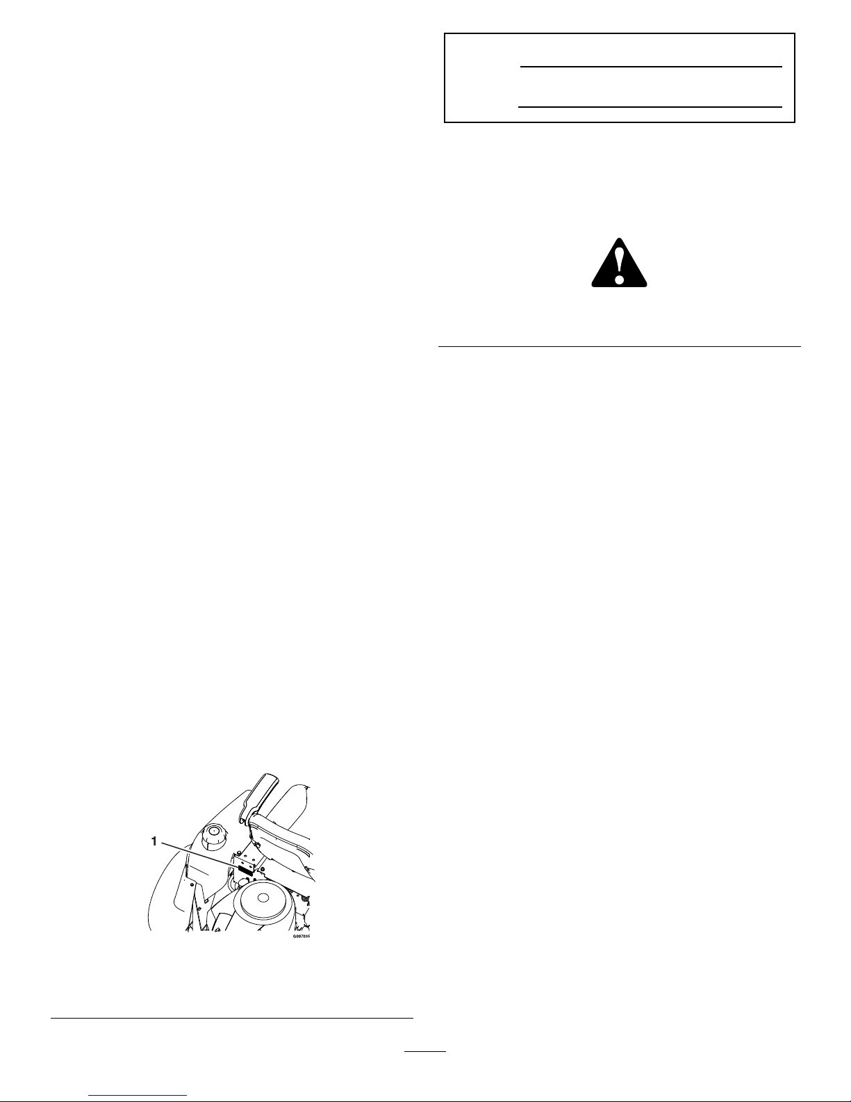
andserialnumbersofyourproductready.identies
thelocationofthemodelandserialnumbersonthe
product.Writethenumbersinthespaceprovided.
Figure1
Behindtheseat
1.Modelandserialnumberlocation
ModelNo.
SerialNo.
Thismanualidentiespotentialhazardsandhas
safetymessagesidentiedbythesafetyalertsymbol
(Figure2),whichsignalsahazardthatmaycauseserious
injuryordeathifyoudonotfollowtherecommended
precautions.
Figure2
1.Safetyalertsymbol
Thismanualuses2otherwordstohighlightinformation.
Importantcallsattentiontospecialmechanical
informationandNoteemphasizesgeneralinformation
worthyofspecialattention.
Contents
Introduction.................................................................2
Safety...........................................................................3
SafeOperatingPractices.......................................3
ToroRidingMowerSafety....................................5
SlopeChart..........................................................7
SafetyandInstructionalDecals.............................8
ProductOverview......................................................12
Controls.............................................................13
Specications.....................................................14
Systems..............................................................14
Dimensions........................................................15
TorqueRequirements.........................................15
Operation...................................................................16
ThinkSafetyFirst...............................................16
RecommendedGasoline.....................................16
CheckingtheEngineOilLevel............................18
StartingtheEngine.............................................18
OperatingtheBlades..........................................19
StoppingtheEngine...........................................19
TheSafetyInterlockSystem................................20
DrivingForwardorBackward.............................20
StoppingtheMachine.........................................21
TrackingAdjustment..........................................21
AdjustingtheHeightofCut................................22
PositioningtheSeat............................................22
ChangingtheSeatRideSuspension.....................22
AdjustingtheMotionControlLevers..................23
PushingtheMachinebyHand.............................23
©2008—TheToro®Company
8111LyndaleAvenueSouth
Bloomington,MN55420
2
Contactusatwww.Toro.com.
PrintedintheUSA.
AllRightsReserved
Page 3

SideDischarge....................................................24
Transporting......................................................24
OperatingTips..................................................25
Maintenance...............................................................26
RecommendedMaintenanceSchedule(s)................26
PremaintenanceProcedures....................................27
RaisingtheSeat..................................................27
AccessingtheBattery.........................................27
Lubrication.............................................................27
GreasingtheBearings.........................................27
EngineMaintenance...............................................28
ServicingtheAirCleaner....................................28
ServicingtheEngineOil.....................................29
ServicingtheSparkPlug.....................................31
CleaningtheBlowerHousing..............................31
FuelSystemMaintenance.......................................32
ReplacingtheFuelFilter.....................................32
ElectricalSystemMaintenance................................33
ChargingtheBattery...........................................33
ServicingtheFusesandRelay..............................35
DriveSystemMaintenance.....................................35
CheckingtheTirePressure.................................35
HydraulicSystemMaintenance...............................36
CheckingtheHydraulicOilLevel........................36
ChangetheHydraulicSystemFilter.....................36
MowerMaintenance...............................................37
ServicingtheCuttingBlades...............................37
LevelingtheMowerDeck...................................38
AdjustingtheBladeSlope...................................39
RemovingtheMowerDeck................................40
MowerBeltMaintenance....................................41
InstallingtheMowerDeck..................................41
ReplacingtheDischargeDeector......................42
Cleaning.................................................................43
WashingtheUndersideoftheMower..................43
Storage.......................................................................44
CleaningandStorage..........................................44
Troubleshooting.........................................................45
Schematics.................................................................47
Safety
ThismachinemeetsorexceedstheB71.1-2003
specicationsoftheAmericanNationalStandards
Institute,ineffectatthetimeofproduction.
However,improperuseormaintenancebythe
operatororownercanresultininjury.Toreduce
thepotentialforinjury,complywiththesesafety
instructionsandalwayspayattentiontothe
safetyalertsymbol,whichmeansCAUTION,
WARNING,orDANGER-"personalsafety
instruction."Failuretocomplywiththeinstruction
mayresultinpersonalinjuryordeath.
SafeOperatingPractices
ThefollowinginstructionsarefromANSIstandard
B71.1-2003.
Thisproductiscapableofamputatinghandsand
feetandthrowingobjects.Alwaysfollowallsafety
instructionstoavoidseriousinjuryordeath.
GeneralOperation
•Read,understand,andfollowallinstructionsin
theoperator’smanualandonthemachinebefore
starting.
•Donotplacehandsorfeetnearrotatingpartsor
underthemachine.Keepclearofthedischarge
openingatalltimes.
•Allowonlyresponsibleadultswhoarefamiliarwith
theinstructionstooperatethemachine.
•Cleartheareaofobjectssuchasrocks,toys,wire,
etc.,whichcouldbepickedupandthrownbythe
blade.
•Besuretheareaisclearofotherpeoplebefore
mowing.Stopthemachineifanyoneentersthearea.
•Nevercarrypassengers.
•Donotmowinreverseunlessabsolutelynecessary.
Alwayslookdownandbehindbeforeandwhile
backingup.
•Beawareofthemowerdischargedirectionanddo
notpointitatanyone.Avoiddischargingmaterial
againstawallorobstruction.Materialmayricochet
backtowardtheoperator.Stoptheblade(s)when
crossinggravelsurfaces.
•Donotoperatethemachinewithoutdeector,
dischargecoverorentiregrasscollectionsystemin
placeandworking.
•Bealert,slowdownandusecautionwhenmaking
turns.Lookbehindandtothesidebeforechanging
directions.
3
Page 4

•Neverleavearunningmachineunattended.Always
turnoffblades,setparkingbrake,stopengine,and
removekeybeforedismounting.
•Turnoffbladeswhennotmowing.Stoptheengine
andwaitforallpartstocometoacompletestop
beforecleaningthemachine,removingthegrass
catcheroruncloggingthedischargechute.
•Operatethemachineonlyindaylightorgood
articiallight.
•Donotoperatethemachinewhileunderthe
inuenceofalcoholordrugs.
•Watchfortrafcwhenoperatingnearorcrossing
roadways.
•Useextracarewhenloadingorunloadingthe
machineintoatrailerortruck.
•Alwaysweareyeprotectionwhenoperatingthe
mower.
•Dataindicatesthatoperators,age60yearsand
above,areinvolvedinalargepercentageofriding
mower-relatedinjuries.Theseoperatorsshould
evaluatetheirabilitytooperatetheridingmower
safelyenoughtoprotectthemselvesandothersfrom
seriousinjury.
•Alwaysfollowtherecommendationsforwheel
weightsorcounterweights.
SlopeOperation
Slopesareamajorfactorrelatedtolossofcontroland
tip-overaccidents,whichcanresultinsevereinjuryor
death.Operationonallslopesrequiresextracaution.If
youcannotbackuptheslopeorifyoufeeluneasyonit,
donotmowit.
•Donotmowslopesgreaterthan15degrees.
•Watchforditches,holes,rocks,dips,andrisesthat
changetheoperatingangle,asroughterraincould
overturnthemachine.
•Choosealowgroundspeedsoyouwillnothaveto
stopwhileoperatingonaslope.
•Donotmowslopeswhengrassiswet.Slippery
conditionsreducetractionandcouldcausesliding
andlossofcontrol.
•Alwayskeepthewheelmotorsengagedwhengoing
downslopes.
•Reducespeedanduseextremecautiononslopes.
•Donotmakesuddenturnsorrapidspeedchanges.
•Removeormarkobstaclessuchasrocks,treelimbs,
etc.fromthemowingarea.Tallgrasscanhide
obstacles.
•Avoidsuddenstartswhenmowinguphillbecause
themowermaytipbackwards.
•Beawarethatlossoftractionmayoccurgoing
downhill.Weighttransfertothefrontwheelsmay
causedrivewheelstoslipandcauselossofbraking
andsteering.
•Alwaysavoidsuddenstartingorstoppingona
slope.Iftireslosetraction,disengagethebladesand
proceedslowlyofftheslope.
•Useextremecarewithgrasscatchersorother
attachments.Thesecanchangethestabilityofthe
machineandcauselossofcontrol.
•Donottrytostabilizethemachinebyputtingyour
footontheground.
•Donotmowneardrop-offs,ditches,steepbanks
orwater.Wheelsdroppingoveredgescancause
rollovers,whichmayresultinseriousinjury,death
ordrowning.
•Useawalkbehindmowerand/orahandtrimmer
neardrop-offs,ditches,steepbanksorwater.
Children
Tragicaccidentscanoccuriftheoperatorisnotalertto
thepresenceofchildren.Childrenareoftenattractedto
themachineandthemowingactivity.Neverassumethat
childrenwillremainwhereyoulastsawthem.
•Keepchildrenoutofthemowingareaandunder
thewatchfulcareofanotherresponsibleadult,not
theoperator.
•Bealertandturnthemachineoffifchildrenenter
thearea.
•Beforeandwhilebackingorchangingdirection,look
behind,down,andside-to-sideforsmallchildren.
•Nevercarrychildren,evenwiththebladesoff.They
mayfalloffandbeseriouslyinjuredorinterferewith
safemachineoperation.
•Childrenwhohavebeengivenridesinthepastmay
suddenlyappearinthemowingareaforanotherride
andberunoverorbackedoverbythemower.
•Neverallowchildrentooperatethemachine.
•Useextracarewhenapproachingblindcorners,
shrubs,trees,theendofafenceorotherobjectsthat
mayobscurevision.
Towing
Ahitchkitisavailableforthismachineandcanbe
obtainedbycontactinganAuthorizedToroDealer.
Donottowwithoutrstinstallingthismanufacturer
4
Page 5

approvedhitch.Thefollowingguidelinesapplywhen
towingwiththeapprovedhitchkitinstalled.
•Towonlywithamachinethathasahitchdesigned
fortowing.Donotattachtowedequipmentexcept
atthehitchpoint.
•Followthemanufacturer’srecommendationfor
weightlimitsfortowedequipmentandtowingon
slopes.
•Neverallowchildrenorothersinorontowed
equipment.
•Onslopes,theweightofthetowedequipmentmay
causelossoftractionandlossofcontrol.
•Travelslowlyandallowextradistancetostop.
Service
SafeHandlingofGasoline:
Toavoidpersonalinjuryorpropertydamage,useextra
carewhenhandlinggasolineandotherfuels.Theyare
ammableandthevaporsareexplosive.
•Extinguishallcigarettes,cigars,pipesandother
sourcesofignition.
•Useonlyanapprovedcontainer.
•Neverremovethegascaporaddfuelwhenthe
engineisrunning.Allowtheenginetocoolbefore
refueling.
•Neverrefuelthemachineindoors.
•Neverstorethemachineorfuelcontainerinside
wherethereisanopename,suchasnearawater
heaterorfurnace.
•Neverllcontainersinsideavehicleoronatruckor
trailerwithaplasticliner.Alwaysplacecontainerson
thegroundawayfromyourvehiclebeforelling.
•Removegas-poweredequipmentfromthetruck
ortrailerandrefuelitontheground.Ifthisisnot
possible,thenrefuelsuchequipmentwithaportable
container,ratherthanfromagasolinedispenser
nozzle.
•Keepthenozzleincontactwiththerimofthefuel
tankorcontaineropeningatalltimesuntilthefueling
iscomplete.Donotuseanozzlelock-opendevice.
•Iffuelisspilledonclothing,changeclothing
immediately.
•Neveroverllthefueltank.Replacegascapand
tightensecurely .
GeneralService:
•Neveroperateamachineinsideaclosedarea.Engine
exhaustcontainscarbonmonoxide,whichisan
odorless,deadlypoisonthatcankillyou.
•Keepnutsandboltstight,especiallytheblade
attachmentbolts.Keepequipmentingood
condition.
•Nevertamperwithsafetydevices.Checktheir
properoperationregularly.
•Keepthemachinefreeofgrass,leaves,orother
debrisbuild-up.Cleanupoilorfuelspillagefuel
soakeddebris.Allowthemachinetocoolbefore
storing.
•Stopandinspecttheequipmentifyoustrikean
object.Repair,ifnecessary,beforerestarting.
•Nevermakeanyadjustmentsorrepairswiththe
enginerunning.
•Grasscatchercomponentsaresubjecttowear,
damageanddeterioration,whichcouldexpose
movingpartsorallowobjectstobethrown.
Frequentlycheckcomponentsandreplacewith
manufacturers’recommendedparts,whennecessary.
•Mowerbladesaresharpandcancut.Wrapthe
blade(s)orweargloves,anduseextracautionwhen
servicingthem.
•Checkforproperbrakeoperationfrequently.Adjust
andserviceasrequired.
•Maintainorreplacesafetyandinstructiondecalsas
necessary.
•UseonlygenuineTororeplacementpartstoensure
thatoriginalstandardsaremaintained.
ToroRidingMowerSafety
Thefollowinglistcontainssafetyinformationspecicto
Toroproductsorothersafetyinformationthatyoumust
knowthatisnotincludedintheANSIstandards.
•Stoptheengine,disconnectsparkplugwire(s)and
removekeybeforeperforminganyservice,repairs,
maintenanceoradjustments.
•Keephands,feet,hair,andlooseclothingawayfrom
attachmentdischargearea,undersideofmowerand
anymovingpartswhileengineisrunning.
•Donottouchequipmentorattachmentpartswhich
maybehotfromoperation.Allowtocoolbefore
attemptingtomaintain,adjustorservice.
•Batteryacidispoisonousandcancauseburns.Avoid
contactwithskin,eyes,andclothing.Protectyour
face,eyes,andclothingwhenworkingwithabattery.
•Batterygasescanexplode.Keepcigarettes,sparks
andamesawayfrombattery.
5
Page 6

•UseonlyToroapprovedattachments.Warrantymay
bevoidedifusedwithunapprovedattachments.
•Ifloadingthemachineontoatrailerortruck,usea
single,full-widthramponly.Therampangleshould
notexceed15degrees.
Note:Determinetheleftandrightsidesofthe
machinefromthenormaloperatingposition.
6
Page 7
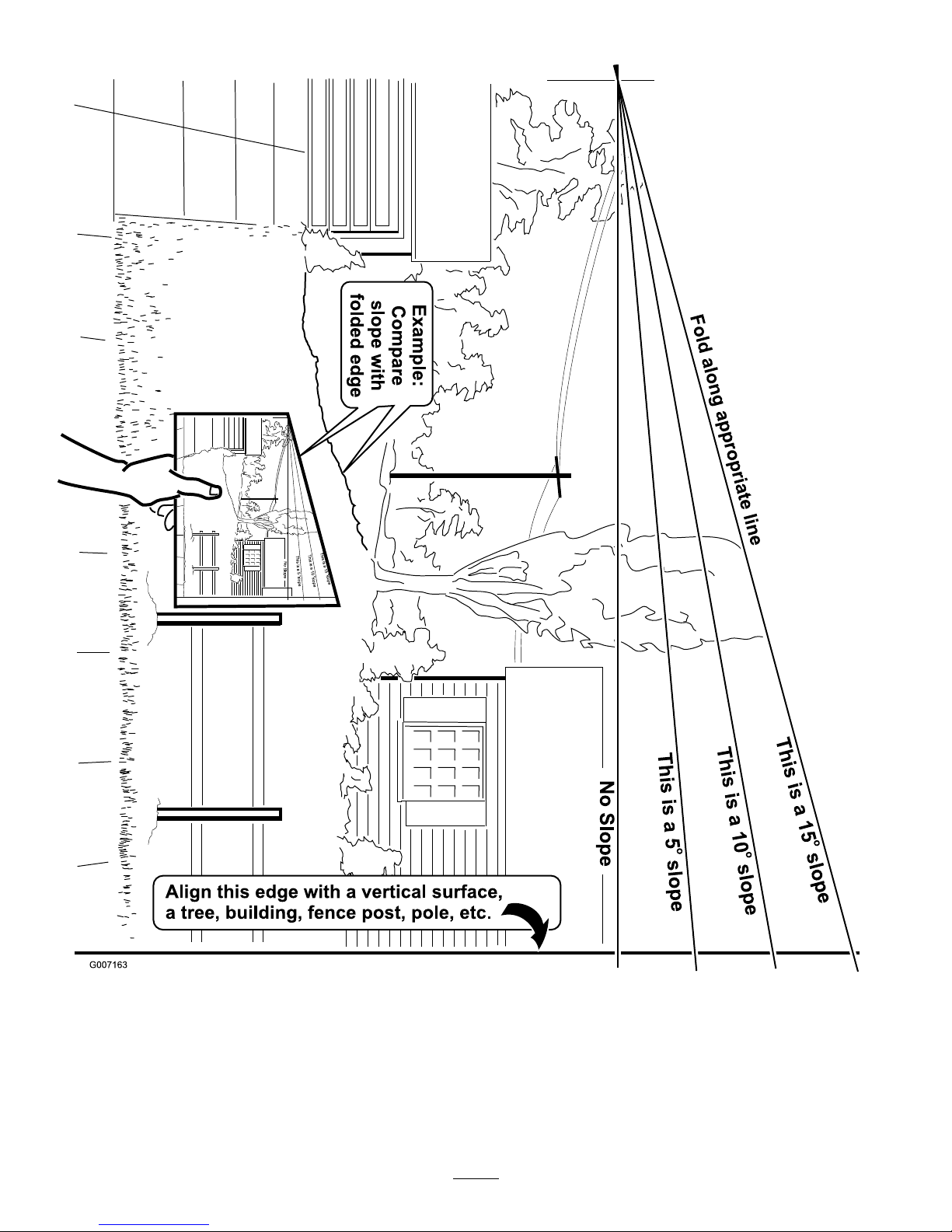
SlopeChart
7
Page 8
SafetyandInstructionalDecals
Safetydecalsandinstructionsareeasilyvisibletotheoperatorandarelocatednearanyareaof
potentialdanger.Replaceanydecalthatisdamagedorlost.
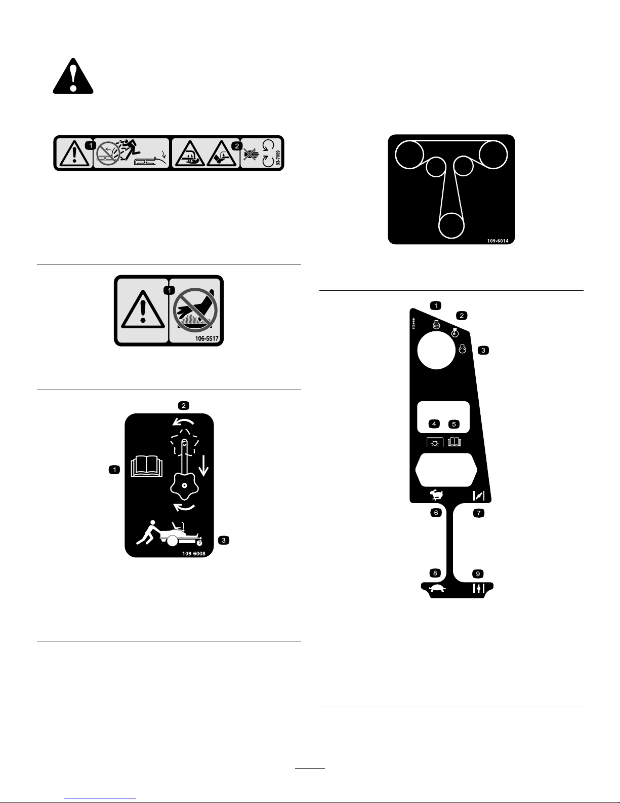
93-7009
1.Warning–DoNotoperate
themowerwiththe
dischargedeectorup
orremoved;keepthe
dischargedeectorin
place.
2.Cutting/dismemberment
hazardofhandorfoot,
mowerblade–stayaway
frommovingparts.
106-5517
1.Warning–DoNottouchthehotsurface.
109-6008
1.ReadtheOperator’s
Manual.
3.Pushthemachine.
2.Rotatethedriverelease
knobtoloosen,slidethe
knob,andtighten.
109-6014
TractionDriveBeltRouting
109-6029
1.Engine–stop
6.Throttle–fast
2.Engine–run
7.Choke–on
3.Engine–start8.Throttle–slow
4.Powertake-off(PTO),
Bladecontrolswitch
9.Choke–off
5.ReadtheOperator’s
Manual.
8
Page 9

109-6035
DeckDriveBeltRouting
109-6036
1.ReadtheOperator’sManual.
2.Removetheignitionkeyandreadtheinstructionsbefore
servicingorperformingmaintenance.
3.Heightofcut.
109-6210
1.ReadtheOperator’sManual.
2.Cutting/dismembermenthazard,fanandentanglement
hazard,belt–stayawayfrommovingparts.
109-6459
1.Entanglementhazard,belt—DoNotopenorremovesafety
shieldswhileengineisrunning,keepshieldsinplace.
109-8759
1.Heightofcut
109-9120
1.Fuse2.Diode
110-6691
1.Thrownobjects
hazard–keepbystanders
asafedistancefromthe
machine.
3.Cutting/dismemberment
ofhandorfoot–stayaway
frommovingparts.
2.Thrownobjectshazard,
mower–keepthe
dischargedeectoror
collectionsysteminplace.
9
Page 10
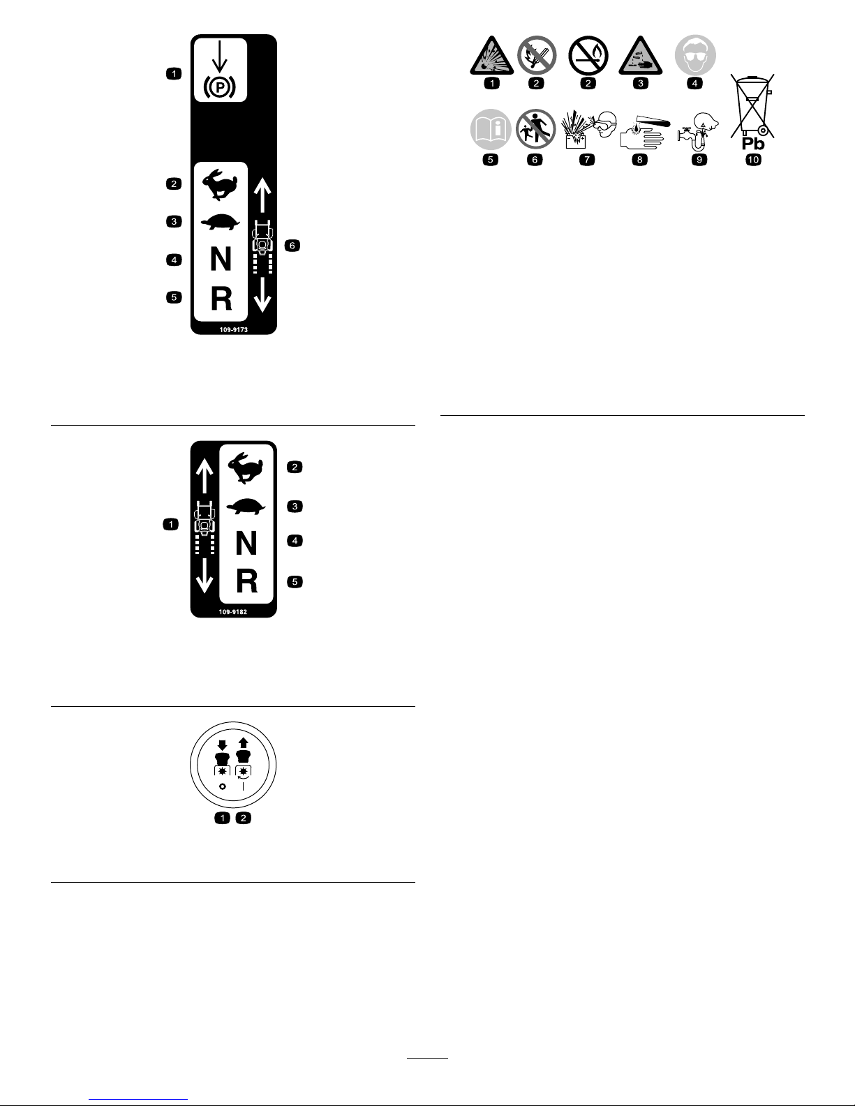
109-9173
1.Parkingbrake4.Neutral
2.Fast5.Reverse
3.Slow6.MachineSpeed
109-9182
1.Machinespeed4.Neutral
2.Fast5.Reverse
3.Slow
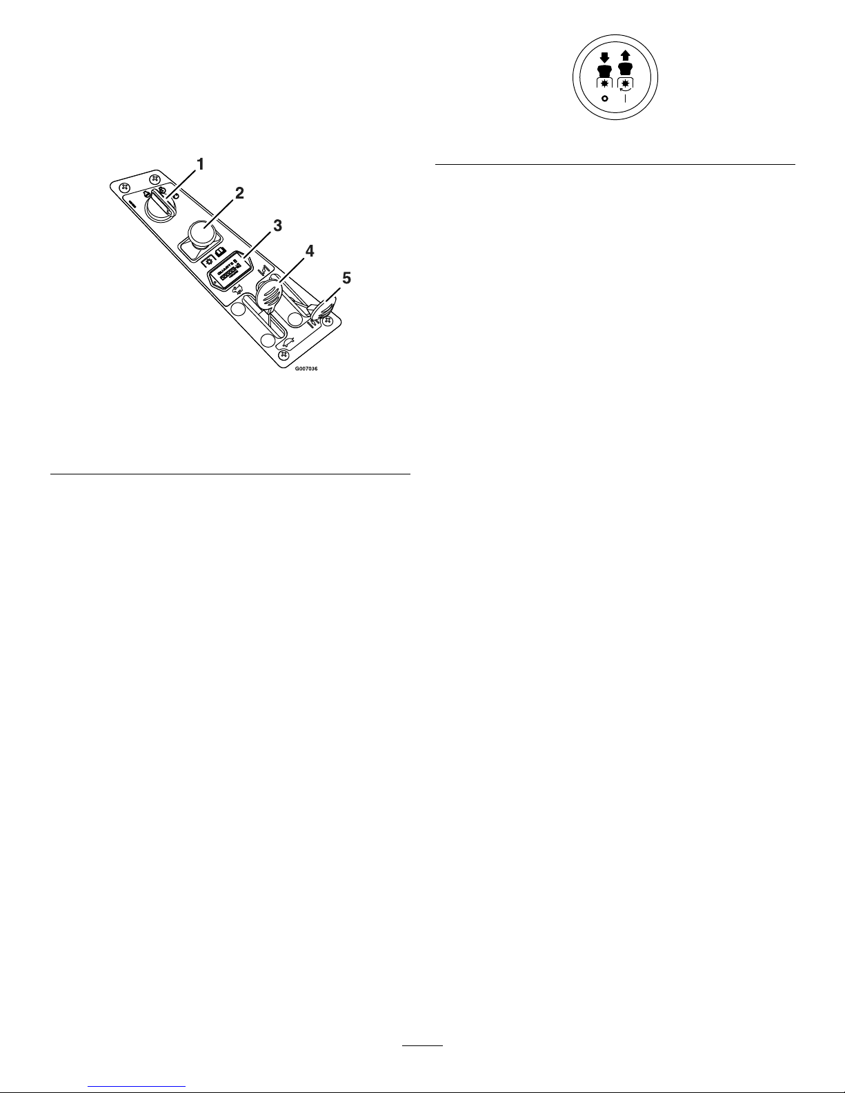
PTOSymbols
1.PTO—Off2.PTO—On
BatterySymbols
Someorallofthesesymbolsareonyourbattery.
1.Explosionhazard
6.Keepbystandersasafe
distancefromthebattery.
2.Nore,openames,or
smoking
7.Weareyeprotection;
explosivegasescan
causeblindnessandother
injuries.
3.Causticliquid/chemical
burnhazard
8.Batteryacidcancause
blindnessorsevereburns.
4.Weareyeprotection9.Flusheyesimmediately
withwaterandgetmedical
helpfast.
5.ReadtheOperator’s
Manual.
10.Containslead;donot
discard.
10
Page 11
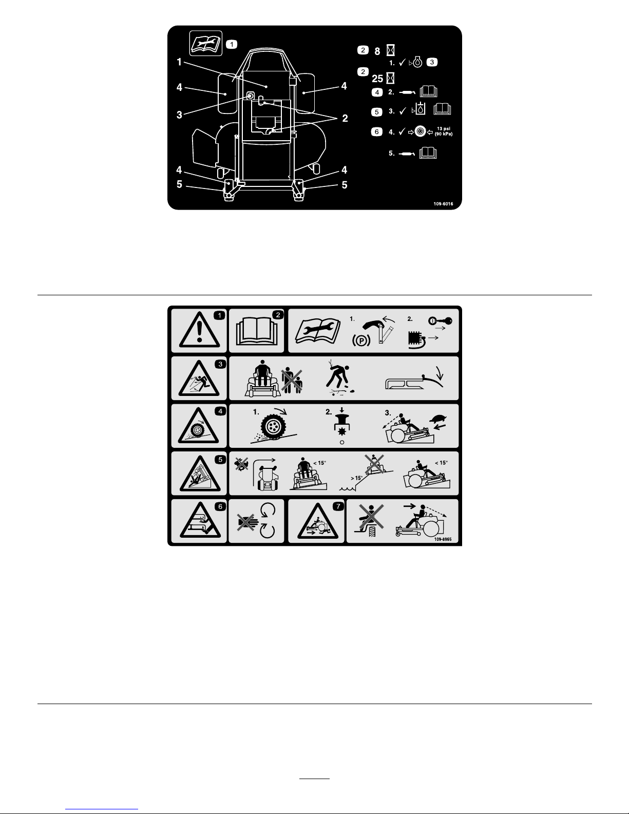
109-6016
1.Readtheinstructionsbeforeservicingorperforming
maintenance.
4.RefertotheOperator’smanualforgreaseinstructions.
2.Timeinterval
5.CheckhydraulicoillevelandrefertotheOperator’sManual
forfurtherinstructions.
3.Checkoillevel.6.Checktirepressure.
109-8965
1.Warning–readtheOperator’sManual.
2.Readtheinstructionsbeforeservicingorperformingmaintenance;applyparkingbrake,removetheignitionkeyanddisconnect
thesparkplugwire.
3.Thrownobjecthazard—keepbystandersasafedistancefromthemachine,pickupdebrisbeforeoperating,keepthedischarge
deectorinplace.
4.Lossoftraction/controlhazard,slopes–lossoftraction/controlonslope,disengagethebladecontrolswitch(PTO),proceed
offtheslopeslowly.
5.Tippinghazard–avoidsuddenandsharpturnswhileonslopes,onlymowacrossslopeslessthan15degrees,keepasafe
distancefromwater,andonlymowupanddownslopeslessthan15degrees.
6.Cutting/dismembermenthazardofhandorfoot,mowerblade–stayawayfrommovingparts.
7.Crushing/dismembermenthazardofbystanders,reversing–DoNotcarrypassengers,lookbehindanddownwhenreversing.
11
Page 12
ProductOverview
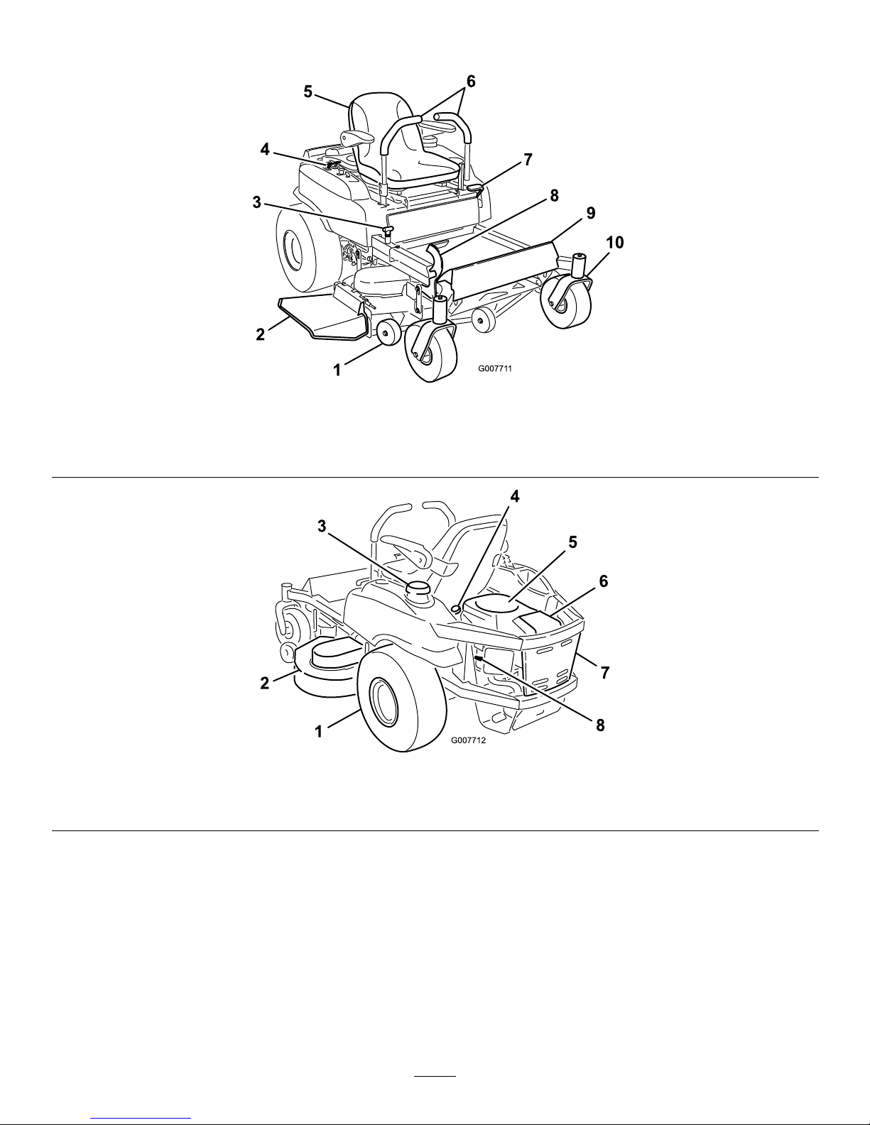
Figure3
1.Anti-scalproller
4.Controlpanel
7.Parkbrake10.Frontcasterwheel
2.Dischargedeector5.Operator’sseat8.Heightofcutfootlever
3.Heightofcutadjustment
6.Motioncontrollevers9.Footrest
Figure4
1.Reardrivewheel
3.Gastank
5.Engine7.Engineguard
2.Mowerdeck4.Engineoildipstick
6.Airlter8.Sparkplugwire(1of2)
12
Page 13
Controls
ControlPanel
Note:Becomefamiliarwithallofthecontrolsbefore
youstarttheengineandoperatethemachine.
Figure5
1.Ignitionswitch4.Throttle
2.Bladecontrolswitch
(powertake-off)
5.Choke
3.Hourmeter
IgnitionSwitch
Theignitionswitchisusedtostartandstoptheengine.
Theswitchhasthreepositions“OFF”,“RUN”and
“START”(Figure5).Insertkeyintoswitchandrotate
clockwisetothe“ON”position.Rotateclockwisetothe
nextpositiontoengagethestarter(keymustbeheld
againstspringpressureinthisposition).
Note:Brakemustbeengaged,motioncontrollevers
out(neutrallockposition)andPTOswitch“OFF”to
startengine.(Itisnotnecessaryfortheoperatortobein
theseattostarttheengine.)
TurningthekeytotheOffpositionwillstoptheengine;
however,alwaysremovethekeywhenleavingthe
machinetopreventsomeonefromaccidentallystarting
theengine
BladeControlSwitch(PowerTake-Off)
Thebladecontrolswitch,representedbyapower
take-off(PTO)symbol(Figure6),engagesand
disengagespowertothemowerblades.Pulloutonthe
bladecontrolswitchto“On”toengagetheblades
Pushthebladecontrolswitchto“Off”todisengage
theblades
Figure6
ChokeControl
Thechokeisusedtoaidinstartingacoldengine.Do
Notrunawarmenginewiththechokeinthe“ON”
position.Movingthechokeleverforwardwillputthe
chokeinthe“ON”positionandmovingthechokelever
totherearwillputthechokeinthe“OFF”position
(Figure5).
ThrottleControl
Thethrottleisusedtocontrolenginespeed.Moving
throttleleverforwardwillincreaseenginespeedand
movingthrottlelevertotherearwilldecreaseengine
speed.Movingthethrottleforwardintothedetentis
fullthrottle(Figure5).
MotionControlLevers
Themotioncontrolleverslocatedoneachsideofthe
seat(Figure3).
Themotioncontrolleversarespeedsensitivecontrols
ofindependentwheelmotors.Movingaleverforward
orbackwardturnsthewheelonthesamesideforward
orinreverse;wheelspeedisproportionaltotheamount
theleverismoved.Movingthecontrolleversoutward
fromthecenterpositionlocksthemintheneutral
position.Alwayspositionthemotioncontrollevers
intotheneutralpositionandengagetheparkbrake
leverwhenyoustopthemachineorleaveitunattended.
Theunitmustbetieddownandbrakeengagedwhen
transporting.
ParkingBrakeLever
Locatedonleftsideoftheconsole(Figure3).
Thebrakeleverengagesaparkingbrakeonthedrive
wheels.
Pulltheleverupandrearwardtoengagethebrake.
Pushtheleverforwardanddowntodisengagethebrake.
Height-of-CutFootLever
Theheightofcutleverallowstheoperatortolowerand
raisethedeckfromtheseatedposition(Figure3).When
theleverismovedforward,awayfromtheoperator
13
Page 14

thedeckisraisedfromthegroundandwhenmoved
back,towardstheoperatoritisloweredtowardthe
ground.Onlyadjusttheheightofcutwhilemachineis
notmoving.
HourMeter
Locatedonthecontrolpanel.
Thehourmeterisconnectedtoapressureswitch
installedintheengineblockanditrecordsthenumber
ofhoursthattheenginehasrun(Figure5).Ifthe
ignitionswitchisleftonwithoutenginerunning,hour
meterwillnotrun.
Note:Thisswitchisnotalowoilsensorandwillnot
alerttheoperatoriftheengineoilislow.
Specications
Systems
Engine
•EngineSpecications:SeeyourEngineOwner’s
Manual
•RPM:FullSpeed:3600±75(max)RPM(NoLoad)
Idle:1750(min)RPM
FuelSystem
•Capacity:4.0gal.(15.1L)
•TypeofFuel:Regularunleadedgasoline,87octane
orhigher.
•FuelFilter:KohlerP/N2405010
•FuelShut-OffValve:1/4turnincrements(“ON”,
“OFF”)
ElectricalSystem
•ChargingSystem:FlywheelAlternator
•ChargingCapacity:15amps
•BatteryType:BCIGroupU1
•BatteryVoltage:12Volt
•Polarity:NegativeGround
•Fuses:One25amp,one20amp;one15ampblade
type
•Diode:TVS
SafetyInterlockSystem
•PTOmustbedisengaged,brakeengaged,and
motioncontrolleversout(neutrallock)tostart
engine.(Itisnotnecessaryfortheoperatortobein
theseattostarttheengine.)
•OperatormustbeinseatwhenPTOisengaged,
brakeisdisengaged,ormotioncontrolleversare
movedinorenginewillstop.
•Enginewillstopifeithertheleft,theright,orboth
leversaremovedfromneutrallockpositionwhile
brakeisengaged.
OperatorControls
•SteeringandMotionControl:
Note:Motioncontrolleversareadjustabletotwo
heights.
–Separatelevers,oneachsideoftheconsole,
controlspeedanddirectionoftravelofthe
respectivedrivewheels.
–Steeringiscontrolledbyvaryingthepositionof
theleversrelativetoeachother.
–Movingmotioncontrolleversoutward(inslots)
locksthedrivesysteminneutral.
•PTOEngagementSwitch:Engageselectricclutch
(todrivebelt)whichengagesmowerblades.
•ParkingBrakeLever:Engagesparkingbrake.
•DeckHeightAdjustmentPin:Setscuttingheight
todesiredposition.
•DeckLiftAssistLever:Footpedalthatassistsin
raisingthedeck.
Seat
•Type:Standardseatwithhighback,foampadded
withspringsuspensionandarmrests.
•Mounting:Hingedtotiltupforaccesstohydraulic
pumps,batteryandothercomponents.Heldintilted
positionwithlanyard.Adjustableforeandaftseat
track.
•Armrests:Standard–foampaddedip-upadjustable
heightarmrests.
•SeatSafetySwitch:IncorporatedintotheSafety
InterlockSystem.
HydrostaticGroundDriveSystem
•HydrostaticPumps:TwoHydroGearZT2800
Integrateddrivesystems.
•HydraulicOilType:UseMobil115W -50Synthetic
motoroil.
•Speeds:
–0-7.0mph(11.3km/hr)forward.
–0-5.0mph(8.0km/hr)reverse.
•Drivewheelreleases,locatedonleftandrightsides
ofenginedeck,allowmachinetobemovedwhenthe
engineisnotrunningandbrakeisoff.
14
Page 15

Tires&Wheels
Drive
FrontCaster
Pneumatic(Air-Filled)
Pneumatic
(Air-Filled)
DeckSize
4852AllDecks
Quantity
222
TreadSizeTurfT ecTurfT ec
AllDecks
Size
20x8.00-820x10.00-810x4
PlyRating44
Pressure13psi
(90kPa)
13psi
(90kPa)
13psi
(90kPa)
CuttingDeck
•CuttingWidth:
–48inchDeck:48inches(122cm)
–52inchDeck:52inches(132cm)
•Discharge:Side
•BladeSize:(3ea.)
–48inchDeck:16.25inches(41.3cm)
–52inchDeck:18.00inches(45.7cm)
•BladeSpindles:Solidsteelspindleswithno
maintenancebearings.
•DeckDrive:Electricclutchmountedonvertical
engineshaft.Bladesaredrivenbyonebelt
(w/self-tensioningidler)directfromtheengine.
•Deck:Fulloatingdeckisattachedtoout-front
supportframe.Maximumturfprotectionisprovided
withthreeanti-scalprollers(bothdecksizes).
Deckdesignallowsforbagging,mulchingorside
discharge.
•DeckDepth:
–46inchDeck:5.0inches(12.7cm)
–52inchDeck:5.0inches(12.7cm)
•CuttingHeightAdjustment:Afootdeckliftleveris
usedtoadjustthecuttingheightfrom11/2inch
(3.8cm)to41/2inches(11.4cm)in1/2inch(1.3
cm)increments.
•MulchingKit:Optional.
Dimensions
OverallWidth:
48inchDeck52inchDeck
WithoutDeck45.5inches
(116cm)
47.0inches
(119cm)
48inchDeck52inchDeck
DeectorUp
48.3inches
(122cm)
53.0inches
(135cm)
DeectorDown
59.4inches
(151cm)
64.2inches
(163cm)
OverallLength:
48inchDeck52inchDeck
73.4inches(186cm)73.4inches(186cm)
OverallHeight:
48inchDeck52inchDeck
41.8inches(106cm)41.8inches(106cm)
TreadWidth:(CentertoCenterofTires,
Widthwise)
48inchDeck52inchDeck
DriveWheels36.0inches
(91cm)
36.8inches
(93cm)
CasterWheels
33.5inches
(85cm)
33.5inches
(85cm)
WheelBase:(CenterofCasterTireto
CenterofDriveTire)
48inchDeck52inchDeck
48.9inches(124cm)48.9inches(124cm)
CurbWeight:
48inchDeck52inchDeck
645lb(293kg)660lb(299kg)
TorqueRequirements
BoltLocationTorque
SpindlePulleyNut95-100ft-lb(1291-142N-m)
BladeMountingBolt
45-55ft-lb(61-75N-m)
EngineMountingBolts
27-33ft-lb(37-45N-m)
Anti-ScalpRollerNylocNut27-33ft-lb(37-45N-m)
WheelLugNuts
70-90ft-lb(95-122N-m)
ClutchMountingBolt(secured
withthreadlocker)
50-55ft-lb(68-75N-m)
SparkPlug15ft-lb(20N-m)
15
Page 16

Operation
Note:Determinetheleftandrightsidesofthe
machinefromthenormaloperatingposition.
ThinkSafetyFirst
Pleasecarefullyreadallofthesafetyinstructionsand
decalsinthesafetysection.Knowingthisinformation
couldhelpyou,yourfamily,petsorbystandersavoid
injury.
Mowingonwetgrassorsteepslopescancause
slidingandlossofcontrol.
Wheelsdroppingoveredgescancauserollovers,
whichmayresultinseriousinjury,deathor
drowning.
Alossoftractionisalossofsteeringcontrol.
Toavoidlossofcontrolandpossibilityof
rollover:
•Donotmowneardrop-offsornearwater.
•Donotmowslopesgreaterthan15degrees.
•Reducespeedanduseextremecautionon
slopes.
•Whenmowingslopes,graduallyworkfrom
lowertohigherareasontheincline.
•Avoidsuddenturnsorrapidspeedchanges.
•Turnup,intoaninclinewhenchanging
directionsonslopes.Turningdownthe
slopereducestraction.
•Attachmentschangethehandling
characteristicsofthemachine.Useextra
cautionwhenusingattachmentswiththe
machine.
Figure7
1.SafeZone-usethemachinehere
2.Usewalkbehindmowerand/orhandtrimmerneardrop-offs
andwater.
3.Water
RecommendedGasoline
UseUNLEADEDRegularGasolinesuitablefor
automotiveuse(87pumpoctaneminimum).
Important:Neverusemethanol,gasoline
containingmethanol,orgasoholcontainingmore
than10%ethanolbecausethefuelsystemcouldbe
damaged.DoNotmixoilwithgasoline.
16
Page 17

Incertainconditionsgasolineisextremely
ammableandvaporsareexplosive.
Areorexplosionfromgasolinecanburnyou,
others,andcausepropertydamage.
•Fillthefueltankoutdoorsinanopenarea,
whentheengineiscold.Wipeupany
gasolinethatspills.
•Neverrellthefueltankordrainthe
machineindoorsorinsideanenclosed
trailer.
•DoNotllthefueltankcompletelyfull.
Addgasolinetothefueltankuntilthebody
ofthetankisfullbutfueldoesnotllthe
neckofthetank.Thisemptyspaceinthe
tankallowsgasolinetoexpand.
•Neversmokewhenhandlinggasoline,and
stayawayfromanopenameorwhere
gasolinefumesmaybeignitedbyspark.
•Storegasolineinanapprovedcontainerand
keepitoutofthereachofchildren.Never
buymorethana30-daysupplyofgasoline.
•DoNotoperatewithoutentireexhaust
systeminplaceandinproperworking
condition.
Incertainconditionsduringfueling,static
electricitycanbereleasedcausingaspark
whichcanignitegasolinevapors.Areor
explosionfromgasolinecanburnyouand
othersandcausepropertydamage.
•Alwaysplacegasolinecontainersonthe
groundawayfromyourvehiclebeforelling.
•DoNotllgasolinecontainersinsidea
vehicleoronatruckortrailerbedbecause
interiorcarpetsorplastictruckbedliners
mayinsulatethecontainerandslowtheloss
ofanystaticcharge.
•Whenpractical,removegas-powered
equipmentfromthetruckortrailerand
refueltheequipmentwithitswheelsonthe
ground.
•Ifthisisnotpossible,thenrefuelsuch
equipmentonatruckortrailerfroma
portablecontainer,ratherthanfroma
gasolinedispensernozzle.
•Ifagasolinedispensernozzlemustbeused,
keepthenozzleincontactwiththerimof
thefueltankorcontaineropeningatall
timesuntilfuelingiscomplete.
Gasolineisharmfulorfatalifswallowed.
Long-termexposuretovaporshascaused
cancerinlaboratoryanimals.Failuretouse
cautionmaycauseseriousinjuryorillness.
•Avoidprolongedbreathingofvapors.
•Keepfaceawayfromnozzleandgas
tank/containeropening.
•Keepawayfromeyesandskin.
•Neversiphonbymouth.
UsingStabilizer/Conditioner
Useafuelstabilizer/conditionerinthemachineto
providethefollowingbenets:
•Keepsgasolinefreshduringstorageof30daysor
less.Forlongerstorageitisrecommendedthatthe
fueltankbedrained.
17
Page 18

•Cleanstheenginewhileitruns.
•Eliminatesgum-likevarnishbuildupinthefuel
system,whichcauseshardstartingAddthecorrect
amountofgasstabilizer/conditionertothegas.
Note:Afuelstabilizer/conditionerismosteffective
whenmixedwithfreshgasoline.Tominimizethe
chanceofvarnishdepositsinthefuelsystem,usefuel
stabilizeratalltimes.
Gasoline/Alcoholblends
Gasohol(upto10percentethylalcohol,90percent
unleadedgasolinebyvolume)isapprovedforfueluse
bytheenginemanufacturer.Othergasoline/alcohol
blendsarenotapproved.
FillingtheFuelTank
1.Shuttheengineoffandsetthemotioncontrolsto
theneutralpositionandengageparkingbrake.
2.Cleanaroundthefueltankcapandremovethecap.
3.Addunleadedregulargasolineuntilthebodyofthe
tankisfullbutfueldoesnotlltheneckofthe
tank(Figure8).Thisspaceintheneckofthetank
allowsgasolinetoexpand.Donotllthefueltank
completelyfull.
Figure8
1.Gastankopening3.Gastankbody
2.Filltohere,approximately
4.Installthefueltankcapsecurely.Wipeupany
gasolinethatmayhavespilled.
CheckingtheEngineOilLevel
Beforeyoustarttheengineandusethemachine,
checktheoillevelintheenginecrankcase;refertothe
CheckingtheOilLevelsectioninEngineMaintenance.
StartingtheEngine
1.Sitdownontheseatandmovethemotioncontrols
outwardtotheneutralpositionandengagethe
parkingbrake.
2.Disengagethebladesbymovingthebladecontrol
switchtoOff(Figure9).
Figure9
1.Controlpanel2.Bladecontrolswitch—Off
position
3.Movethethrottlelevertomidwayandthe
chokeleverforwardbeforestartingacoldengine
(Figure10).
Note:Awarmorhotenginemaynotrequire
choking.
Figure10
1.Controlpanel
4.Throttle—slow
2.Choke—on5.Throttle—fast
3.Choke–off
4.TurntheignitionkeytoStarttoenergizethestarter.
Whentheenginestarts,releasethekey(Figure11).
Important:Donotengagethestarterformore
than5secondsatatime.Iftheenginefails
tostart,allowa60secondcool-downperiod
betweenattempts.Failuretofollowthese
instructionscanburnoutthestartermotor.
18
Page 19

Figure11
1.Ignitionkey—startposition
4.Start
2.Controlpanel
5.Run
3.Choke6.Off
5.Iftheenginestallsorhesitates,movethechoke
leverpartiallyforwardforafewseconds(Figure11).
OperatingtheBlades
Thebladecontrolswitch,representedbyapower
take-off(PTO)symbol,engagesanddisengagespower
tothemowerblades.Thisswitchcontrolspowertoany
attachmentsthatdrawpowerfromtheengine,including
themowerdeckandcuttingblades.
EngagingtheBlades
1.Releasepressureonthemotioncontrolleversand
placethemachineinneutral.
2.MovethethrottlemidwaytotheFastposition.
Note:Alwaysengagethebladeswiththethrottle
inthemidwayposition.
3.PulloutonthebladecontrolswitchtoOnto
engagetheblades(Figure12).
Figure12
1.Controlpanel2.Bladecontrolswitch—On
position
4.Movethrottletofullforwardpositionbefore
mowing.
DisengagingtheBlades
Setthrottletomidwayposition.Pushthebladecontrol
switchtoOfftodisengagetheblades(Figure13).
Figure13
1.Controlpanel2.Bladecontrolswitch—Off
position
StoppingtheEngine
1.MovethethrottlelevertobetweenFastandhalf
throttle(Figure11).
2.Disengagethebladesbymovingthebladecontrol
switchtoOff(Figure13).
3.TurntheignitionkeytoOff(Figure11).
4.Pullthewireoffofthesparkplug(s)toprevent
thepossibilityofsomeoneaccidentallystartingthe
machinebeforetransportingorstoringthemachine.
19
Page 20

TheSafetyInterlockSystem
Ifsafetyinterlockswitchesaredisconnected
ordamagedthemachinecouldoperate
unexpectedlycausingpersonalinjury.
•DoNottamperwiththeinterlockswitches.
•Checktheoperationoftheinterlock
switchesdailyandreplaceanydamaged
switchesbeforeoperatingthemachine.
UnderstandingtheSafetyInterlock
System
Thesafetyinterlocksystemisdesignedtopreventthe
enginefromstartingunless:
•Thebladesaredisengaged.
•Themotioncontrolleversareintheneutral
position.
•Theparkingbrakeisengaged.
Thesafetyinterlocksystemisdesignedtoinitiateengine
shutdownwhen:
•Theparkingbrakeisdisengagedandtheoperator
getsoffmachine.
•ThePTOisengagedandtheoperatorgetsoff
machine.
•Theparkingbrakeisdisengagedandleversarein
andtheoperatorgetsoffmachine.
•Theparkingbrakeisengagedandmotioncontrol
leversarein.
TestingtheSafetyInterlockSystem
Testthesafetyinterlocksystembeforeyouusethe
machineeachtime
1.Checkstartingcircuit.Startershouldcrankwith
parkingbrakeengaged,PTOdisengagedand
motioncontrolleversmovedoutintheneutral
lockposition.Theoperatordoesnotneedtobein
theseattostarttheengine.
Trytostartwithoperatorinseat,parkingbrake
disengaged,PTOdisengagedandmotioncontrol
leversintheneutrallockposition-startermust
notcrank.
Trytostartwithoperatorinseat,parkingbrake
engaged,PTOengagedandmotioncontrollevers
intheneutrallockposition-startermustnot
crank.
Trytostartwithoperatorinseat,parkingbrake
engaged,PTOdisengaged,andtheleftmotion
controlleverin,startermustnotcrank,repeat
againwiththerightleverin,thenwithbothlevers
in-startermustnotcrank.
2.Checkkillcircuits.Runengineatone-thirdthrottle,
disengageparkingbrakeandraiseoffofseat(but
donotgetoffofmachine)enginemustinitiate
shutdown.
Runengineatone-thirdthrottle,engagePTOand
raiseoffofseat(butdonotgetoffofmachine)
enginemustinitiateshutdown.
Runengineatone-thirdthrottle,withbrake
disengaged,moveleversinandraiseoffseat(but
donotgetoffofmachine)enginemustinitiate
shutdown.
Again,runengineatone-thirdthrottle,brake
engaged,andmoveleftmotioncontrolleverin-
enginemustinitiateshutdown.
Repeatagainmovingtherightleverin,then
movingbothleversin-enginemustinitiate
shutdownwhetheroperatorisonseatornot.
Note:Ifmachinedoesnotpassanyofthesetests,
donotoperate.ContactyourauthorizedToroService
Dealer.
Important:Itisessentialthatoperatorsafety
mechanismsbeconnectedandinproperoperating
conditionpriortouseformowing.
DrivingForwardorBackward
Thethrottlecontrolregulatestheenginespeedas
measuredinrpm(revolutionsperminute).Place
thethrottlecontrolintheFastpositionforbest
performance.AlwaysoperateintheFast(fullthrottle)
position.
Machinecanspinveryrapidlybypositioning
onelevertoomuchaheadoftheother.Operator
maylosecontrolofthemachine,whichmay
causedamagetothemachineorinjury.
•Usecautionwhenmakingturns.
•Slowthemachinedownbeforemaking
sharpturns.
20
Page 21

Forward
1.Movetheleverstothecenter,unlockedposition.
2.Togoforward,slowlypushthemotioncontrol
leversforward(Figure14).
Figure14
1.Neutralposition3.Backward
2.Centerunlockposition
4.Forward
Togostraight,applyequalpressuretobothmotion
controllevers(Figure14).
Toturn,pullbackonthemotioncontrollever
towardthedirectionyouwanttoturn(Figure14).
Thefartheryoumovethemotioncontrolleversin
eitherdirection,thefasterthemachinewillmovein
thatdirection.
Tostop,pullthemotioncontrolleverstoneutral.
Backward
1.Movetheleverstothecenter,unlockedposition.
2.Togobackward,slowlypullthemotioncontrol
leversrearward(Figure14).
Togostraight,applyequalpressuretobothmotion
controllevers(Figure14).
Toturn,releasethepressureonthemotion
controllevertowardthedirectionyouwanttoturn
(Figure14).
Tostop,pushthemotioncontrolleverstoneutral.
StoppingtheMachine
Tostopthemachine,movethemotioncontrolleversto
neutralandoutwardtotheneutralposition,disengage
thebladecontrolswitch,movethethrottleleverto
betweenFastandhalfthrottle,andturntheignitionkey
tooff.Remembertoremovethekeyfromtheignition
switch.
TrackingAdjustment
Ifthemachineturnsrightorleftwhenhandlesare
pushedforwardtogether,adjustthestopontheside
oppositethedirectionofturn(Figure15).Loosenthe
screwsthatholdthemotioncontrollimiterstop.Move
thestopbackuntiltheunitdrivesstraight.Tighten
thescrewstolockthestopinplace.Readjusthandles
ifnecessary.
Figure15
1.Controlarmshaft
3.Adjuststop
2.Limiterstopscrews
Childrenorbystandersmaybeinjuredifthey
moveorattempttooperatethemowerwhileit
isunattended.
Alwaysremovetheignitionkeyandmovethe
motioncontrolleversoutwardtotheneutral
positionandapplytheparkingbrakewhen
leavingthemachineunattended,evenifjustfor
afewminutes.
21
Page 22

AdjustingtheHeightofCut
1.Raisethedecktothetransportposition(4.5inch
(114mm)cutheight)bypushingthefootactuated
leverforward(Figure16).Thespringloaded
transportpinwillautomaticallyengageandwillclick
intoplace.
Figure16
1.Pushforward
4.Heightadjusterpin
2.Footactuated
height-of-cutlever
5.Transportreleasehandle
3.Height-of-cutpositions
2.Movethedeckheightadjusterpintothedesired
cutheight.
3.Pushthefootleverforward,pullthetransport
releasehandleupandletthedecklowerdowntothe
predeterminedcutheightbyslowlydecreasingfoot
pressureallowingthefootlevertotravelrearward.
PositioningtheSeat
Theseatcanmoveforwardandbackward.Positionthe
seatwhereyouhavethebestcontrolofthemachine
andaremostcomfortable.
1.Pushtheadjustmentlevertowardsthecenter
ofthemachinetoreleasetheseatadjustertrack
(Figure17).
Figure17
1.Adjustmentlever
2.Movetheseattothedesiredpositionandrelease
thelevertolockinthatposition.
ChangingtheSeatRide
Suspension
Thenumberofseatspringscanbechangedto
maximizeridercomfort.Morespringsshouldbeused
withheavieroperatorsandonroughterrain.Fewer
springsshouldbeusedwithlighteroperatorsandwhen
mowingsmooth,wellestablishedlawns.Alwayskeep
thenumberofspringsontheleftandrightsidethe
samewhenaddingandremovingsprings.
Figure18
1.Bolt3.Nut
2.Spring
4.Additionalmountingholes
Uptovespringscanbesecuredtotheseatboxwitha
nutandbolt,seeFigure18.
RefertoyourPartsManualforspringandhardware
partnumbers.
22
Page 23

AdjustingtheMotionControl
Levers
AdjustingtheHeight
Themotioncontrolleverscanbeadjustedhigheror
lowerformaximumoperatorcomfort.
1.Removethetwoboltsholdingthecontrolleverto
thecontrolarmshaft(Figure19).
Figure19
1.Controlarmshaft
4.Bolt
2.Controllever5.Slottedholes
3.Washer
2.Movethecontrollevertothenextsetofholes.
Securetheleverwiththetwobolts.
3.Repeattheadjustmentfortheoppositecontrol
lever.
AdjustingtheTilt
Themotioncontrolleverscanbetiltedforeoraftfor
maximumoperatorcomfort.
1.Loosentheupperboltholdingthecontrolleverto
thecontrolarmshaft.
2.Loosenthelowerboltjustenoughtopivotthe
controlleverforeoraft(Figure19).Tightenboth
boltstosecurethecontrolinthenewposition.
3.Repeattheadjustmentfortheoppositecontrol
lever.
PushingtheMachinebyHand
Important:Alwayspushthemachinebyhand.
Nevertowthemachinebecausedamagemay
occur.
ToPushtheMachine
1.Parkthemachineonalevelsurfaceanddisengage
thebladecontrolswitch.
2.Movethemotioncontrolleversoutwardtoneutral
position,engageparkingbrake,stoptheengine,
removethekey,andwaitforallmovingpartsto
stopbeforeleavingtheoperatingposition.
3.Locatethebypassreleaseknobsoneithersideof
theenginedeck(Figure20).
Figure20
1.Frontofthemachine.5.Leverpositionforpushing
themachine
2.Rotatebypassrelease
knobcounterclockwise
6.Rotatebypassrelease
knobclockwise
3.Leverpositionfor
operatingthemachine.
7.Releaselever
4.Pullleverinthisdirection
4.Loosentheknobbyturningcounterclockwise.
Thenpullthereleaseleverontheundersideof
machine(Figure20)towardsthebackofthe
machineandretightentheknobtoholdtherelease
leverbackinthereleasedstate.Repeatthisoneach
sideofthemachine.
5.Releasetheparkingbrake.Themachineisnowable
tobepushedbyhand.
ToOperatetheMachine
Loosenthebypassknob,pushthereleaselevers
forward,andretightentheknobtoengagethedrive
system(Figure20).
23
Page 24

SideDischarge
Themowerhasahingeddischargedeectorthat
dispersesclippingstothesideanddowntowardtheturf.
Withoutthedischargedeector,mulchkit,or
entiregrasscollectionsystemmountedinplace,
youandothersareexposedtobladecontactand
throwndebris.Contactwithrotatingmower
blade(s)andthrowndebriswillcauseinjuryor
death.
•Neverremovethedischargedeectorfrom
themowerbecausethedischargedeector
routesmaterialdowntowardtheturf.Ifthe
dischargedeectoriseverdamaged,replace
itimmediately .
•Neverputyourhandsorfeetunderthe
mower.
•Nevertrytocleardischargeareaormower
bladesunlessyoumovethemovetheblade
controlswitchtoOffandrotatetheignition
keytoOff.Alsoremovethekeyandpullthe
wireoffthesparkplug(s).
Transporting
TransportingaUnit
Useaheavy-dutytrailerortrucktotransportthe
machine.Lockbrakeandblockwheels.Securelyfasten
themachinetothetrailerortruckwithstraps,chains,
cable,orropes.Besurethatthetrailerortruckhas
allnecessarylightingandmarkingasrequiredbylaw.
Secureatrailerwithasafetychain.
Thisunitdoesnothaveproperturnsignals,
lights,reectivemarkings,oraslowmoving
vehicleemblem.Drivingonastreetorroadway
withoutsuchequipmentisdangerousand
canleadtoaccidentscausingpersonalinjury.
Drivingonastreetorroadwaywithoutsuch
equipmentmayalsobeaviolationofStatelaws
andtheoperatormaybesubjecttotrafctickets
and/ornes.
DoNotdriveaunitonapublicstreetor
roadway.
Loadingaunitonatrailerortruckincreases
thepossibilityofbackwardtip-over.Backward
tip-overcouldcauseseriousinjuryordeath.
•Useextremecautionwhenoperatingaunit
onaramp.
•Useonlyasingle,fullwidthramp;DoNot
useindividualrampsforeachsideofthe
unit.
•Ifindividualrampsmustbeused,use
enoughrampstocreateanunbrokenramp
surfacewiderthantheunit.
•DoNotexceeda15degreesanglebetween
rampandgroundorbetweenrampand
trailerortruck.
•Avoidsuddenaccelerationwhiledrivingunit
uparamptoavoidtippingbackward.
•Avoidsuddendecelerationwhilebacking
unitdownaramptoavoidtippingbackward.
LoadingaUnit
Useextremecautionwhenloadingunitsontrailersor
trucks.Onefullwidthrampthatiswideenoughto
extendbeyondthereartiresisrecommendedinstead
ofindividualrampsforeachsideoftheunit.The
lowerrearsectionofthetractorframeextendsback
betweentherearwheelsandservesasastopfortipping
backward.Havingafullwidthrampprovidesasurface
fortheframememberstocontactiftheunitstartsto
tipbackward.Ifitisnotpossibletouseonefullwidth
ramp,useenoughindividualrampstosimulateafull
widthcontinuousramp.
Rampshouldbelongenoughsothattheanglesbetween
therampandthegroundandtherampandthetrailer
ortruckdonotexceed15degrees.Asteeperanglemay
causemowerdeckcomponentstogetcaughtastheunit
movesfromramptotrailerortruck.Steeperangles
mayalsocausetheunittotipbackward.Ifloadingon
ornearaslope,positionthetrailerortrucksoitison
thedownsideoftheslopeandtherampextendsupthe
slope.Thiswillminimizetherampangle.Thetraileror
truckshouldbeaslevelaspossible.
Important:DoNotattempttoturntheunitwhile
ontheramp,youmaylosecontrolanddriveoff
theside.
24
Page 25

Avoidsuddenaccelerationwhendrivinguparampand
suddendecelerationwhenbackingdownaramp.Both
maneuverscancausetheunittotipbackward.
OperatingTips
FastThrottleSetting
Forbestmowingandmaximumaircirculation,operate
theengineattheFastposition.Airisrequiredto
thoroughlycutgrassclippings,sodonotsetthe
height-of-cutsolowastototallysurroundthemower
byuncutgrass.Alwaystrytohaveonesideofthe
mowerfreefromuncutgrass,whichallowsairtobe
drawnintothemower.
CuttingaLawnfortheFirstTime
Cutgrassslightlylongerthannormaltoensurethatthe
cuttingheightofthemowerdoesnotscalpanyuneven
ground.However,thecuttingheightusedinthepastis
generallythebestonetouse.Whencuttinggrasslonger
thansixinchestall,youmaywanttocutthelawntwice
toensureanacceptablequalityofcut.
Cut1/3oftheGrassBlade
Itisbesttocutonlyabout1/3ofthegrassblade.
Cuttingmorethanthatisnotrecommendedunless
grassissparse,oritislatefallwhengrassgrowsmore
slowly.
MowingDirection
Alternatemowingdirectiontokeepthegrassstanding
straight.Thisalsohelpsdisperseclippingswhich
enhancesdecompositionandfertilization.
MowatCorrectIntervals
Normally,moweveryfourdays.Butremember,
grassgrowsatdifferentratesatdifferenttimes.So
tomaintainthesamecuttingheight,whichisagood
practice,mowmoreofteninearlyspring.Asthegrass
growthrateslowsinmidsummer,mowlessfrequently.
Ifyoucannotmowforanextendedperiod,rstmow
atahighcuttingheight;thenmowagaintwodayslater
atalowerheightsetting.
CuttingSpeed
Toimprovecutquality,useaslowergroundspeed.
AvoidCuttingTooLow
Ifthecuttingwidthofthemoweriswiderthanthe
moweryoupreviouslyused,raisethecuttingheightto
ensurethatuneventurfisnotcuttooshort.
LongGrass
Ifthegrassiseverallowedtogrowslightlylongerthan
normal,orifitcontainsahighdegreeofmoisture,raise
thecuttingheighthigherthanusualandcutthegrassat
thissetting.Thencutthegrassagainusingthelower,
normalsetting.
WhenStopping
Ifthemachine’sforwardmotionmustbestoppedwhile
mowing,aclumpofgrassclippingsmaydropontoyour
lawn.T oavoidthis,moveontoapreviouslycutarea
withthebladesengaged.
KeeptheUndersideoftheMower
Clean
Cleanclippingsanddirtfromtheundersideofthe
moweraftereachuse.Ifgrassanddirtbuildupinside
themower,cuttingqualitywilleventuallybecome
unsatisfactory.
BladeMaintenance
Maintainasharpbladethroughoutthecuttingseason
becauseasharpbladecutscleanlywithouttearingor
shreddingthegrassblades.Tearingandshreddingturns
grassbrownattheedges,whichslowsgrowthand
increasesthechanceofdisease.Checkthecutterblades
dailyforsharpness,andforanywearordamage.File
downanynicksandsharpenthebladesasnecessary.Ifa
bladeisdamagedorworn,replaceitimmediatelywitha
genuineTororeplacementblade.OnlyT orobladesare
tobeusedwiththisunit.Nootherbladesareapproved.
25
Page 26

Maintenance
RecommendedMaintenanceSchedule(s)
MaintenanceService
Interval
MaintenanceProcedure
Aftertherst5hours
•Changetheengineoil.
Aftertherst200hours
•Changethehydraulicsystemlter.
Beforeeachuseordaily
•Checkthesafetyinterlocksystem.
•Checktheaircleanerfordirty,looseordamagedparts.
•Checktheoillevelbeforestartingorafterevery8hours.
•Checkthehydraulicoillevelintheexpansiontank.
•Checkthemowerblades.
•Cleantheundersideofthemowerhousing.
Every25hours
•Greasealllubricationpoints.
•Servicetheprecleanerelement.(moreoftenunderextremelydusty ,dirtyconditions)
•Changetheengineoilandlterwhenoperatingtheengineunderheavyloadorin
hightemperatures.
•Checkthetirepressure.
•Checkthebelts.
Every50hours
•Servicethepaperelement.(moreoftenunderextremelydusty,dirtyconditions)
•Changetheengineoilandlter.
Every100hours
•Replacetheprecleanerelement.(moreoftenunderextremelydusty ,dirtyconditions)
•Replacethepaperelement.(moreoftenunderextremelydusty,dirtyconditions)
•Cleantheblowerhousing.Moreoftenunderdirtyconditions.
•Replacethefuellter.
Every200hours
•Servicethesparkplug.
Every500hours
•Replacethesparkplug.
Beforestorage
•Chargethebatteryanddisconnectthebatterycables.
•Performallmaintenanceproceduresbeforestorage.
•Paintanychippedsurfaces.
26
Page 27

Premaintenance
Procedures
RaisingtheSeat
Makesurethemotioncontrolleversarelockedinthe
neutralposition.Lifttheseatforwarduntilthelanyard
istight.Thefollowingcomponentscanbeaccessedby
raisingtheseat:
•Auxiliary12VPlug(12Vaccessoryupto15amp)
•Fuses
•Batterycables
AccessingtheBattery
Thebatteryislocatedundertheseat.Toaccess,raise
theseat(Figure21).
Figure21
1.Auxiliary12VPlug
3.Seat
2.Battery
Lubrication
GreasingtheBearings
GreaseType:NGLIgrade#2multi-purposegungrease.
Greasethefrontcasterpivotsandwheels(Figure22).
1
G007184
Figure22
1.Frontcastertire
1.Parkthemachineonalevelsurfaceanddisengage
thebladecontrolswitch.
2.Movethemotioncontrolleversoutwardtothe
neutralposition,engageparkingbrake,stopthe
engine,removethekey,andwaitforallmovingparts
tostopbeforeleavingtheoperatingposition.
3.Cleanthegreasettings(Figure22andFigure23)
witharag.Makesuretoscrapeanypaintoffofthe
frontofthetting(s).
27
Page 28

Figure23
Locatedonthebackoftheseat.
1.Readtheinstructions
beforeservicingor
performingmaintenance
4.Checkoillevel.
2.Greaseidlerpivots.5.Checkhydraulicoillevel
andrefertoOperator’s
manualforfurther
instructions.
3.Timeinterval.
6.Checktirepressure.
4.Connectagreaseguntoeachtting(Figure22and
Figure23).Pumpgreaseintothettingsuntilgrease
beginstooozeoutofthebearings.
5.Wipeupanyexcessgrease.
EngineMaintenance
ServicingtheAirCleaner
ServiceInterval:Beforeeachuseordaily—Checkthe
aircleanerfordirty,looseordamaged
parts.
Thisengineisequippedwithareplaceable,highdensity
paperaircleanerwithafoamprecleanersurrounding
it.Checktheaircleanerdailyorbeforestartingthe
engine.Checkforabuildupofdirtanddebrisaround
theaircleanersystem.Keepthisareaclean.Alsocheck
forlooseordamagedcomponents.Replaceallbentor
damagedaircleanercomponents.
Note:Operatingtheenginewithlooseordamagedair
cleanercomponentscouldallowunlteredairintothe
enginecausingprematurewearandfailure.
Note:Servicetheaircleanermoreoftenunder
extremelydusty,dirtyconditions.
Figure24
1.Aircleanercover3.Paperelement
2.Aircleanerlatch4.Aircleanerbase
ServicingPrecleanerElement
ServiceInterval:Every25hours—Servicethe
precleanerelement.(moreoften
underextremelydusty ,dirty
conditions)
Every100hours—Replacethe
precleanerelement.(moreoften
28
Page 29

underextremelydusty ,dirty
conditions)
1.Opentheaircleanercoverdoorontheblower
housingtoaccesstheaircleanerelement(Figure24).
2.Unhookthelatchandremovetheaircleanerelement
(Figure24).
3.Cleantheaircleanerbaseasrequiredandcheck
condition.
4.Carefullyremovetheprecleanerfromthepaper
element.Inspecttheprecleanerforanydamageor
tears.Replaceasnecessary.
5.Washtheprecleanerinwarmwaterwithdetergent.
Rinsetheprecleanerthoroughlyuntilalltracesof
detergentareeliminated.Squeezeoutexcesswater
(donotwring)andallowtheprecleanertoairdry.
6.Saturatetheprecleanerwithnewengineoil.Squeeze
outallexcessoil.
7.Installtheprecleaneroverthepaperelement.
8.Installtheaircleanerontotheaircleanerbase.
Securewiththelatch.
9.Closetheaircleanercoverdoor.
ServicingPaperElement
ServiceInterval:Every50hours—Servicethepaper
element.(moreoftenunderextremely
dusty,dirtyconditions)
Every100hours—Replacethepaper
element.(moreoftenunderextremely
dusty,dirtyconditions)
1.Opentheaircleanercoverdoorontheblower
housingtoaccesstheaircleanerelement(Figure24).
2.Unhookthelatchandremovetheaircleanerelement
(Figure24).
3.Carefullyremovetheprecleanerfromthepaper
element.Inspecttheprecleanerforanydamageor
tears.Replaceasnecessary.
4.Gentlytapthepaperelementtodislodgedirt.Do
notwashthepaperelementorusepressurized
air,asthiswilldamagetheelement.Replaceadirty,
bent,ordamagedelement.Handlethenewelement
carefully;donotuseifthesealingsurfacesarebent
ordamaged.
5.Cleantheaircleanerbaseasrequiredandcheck
condition.
6.Installtheairelementontotheaircleanerbase.
Securewiththelatch.
7.Closetheaircleanercoverdoor.
ServicingtheEngineOil
CheckingtheOilLevel
ServiceInterval:Beforeeachuseordaily
1.Parkthemachineonalevelsurface,disengagethe
bladecontrolswitch,stoptheengine,engageparking
brake,andremovethekey .
2.Makesuretheengineisstopped,level,andiscoolso
theoilhashadtimetodrainintothesump.
3.Tokeepdirt,grassclippings,etc.,outoftheengine,
cleantheareaaroundtheoilllcap/dipstickbefore
removingit.
4.Pullandremovetheoilllcap/dipstick;wipeoil
off.Reinsertthedipstickandpushrmlyintoplace
(Figure25).
Figure25
1.Oildipstick3.Oillevel
2.Fillertube
5.Removethedipstickandchecktheoillevel.
Theoillevelshouldbeupto,butnotover,the“F”
markonthedipstick.
6.Ifthelevelislow ,addoilofthepropertype,upto
the“F”markonthedipstick.Alwayscheckthelevel
withthedipstickbeforeaddingmoreoil.
Note:Topreventextensiveenginewearordamage,
alwaysmaintaintheproperoillevelinthecrankcase.
Neveroperatetheenginewiththeoillevelbelowthe
“L”markoroverthe“F”markonthedipstick.
ChangingtheOilandFilter
ServiceInterval:Aftertherst5hours
Every50hoursthereafter.
29
Page 30

Every25hours
OilType:Detergentoil(APIserviceSF ,SG,SH,SJ,or
higher).
CrankcaseCapacity:2.0qt(1.9l)whenthelteris
changed.
RellwithserviceclassSF,SG,SH,SJorhigheroilas
speciedinthe“ViscosityGrades”table(Figure26).
Figure26
ViscosityGrades
SAE30:40degreesFandhigher(5degreesCand
higher)isgoodforallpurposeuseabove40degreesF.
Usebelow40degreesFwillcausehardstarting.
10W-30:0to100degreesF(-18to38degreesC)is
betterforvaryingtemperatureconditions.Thisviscosity
improvescoldweatherstarting,butmayincreaseoil
consumptionabove80degreesF(27degreesC).
*Checkoillevelfrequentlyathighertemperatures.
Synthetic5W-30:-20to120degreesF(-30to
40degreesC)providesthebestprotectioninall
temperatures,aswellasimprovedstartingwithlessoil
consumption.
5W-30:40degreesFandbelow(5degreesCandbelow)
isrecommendedforwinteruseandworksbestincold
conditions.
Changetheoilandlterwhiletheengineisstillwarm.
Theoilwillowmorefreelyandcarryawaymore
impurities.Makesuretheengineislevelwhenlling,
checking,orchangingtheoil.
1.Starttheengineandletitrununtilwarm.This
warmstheoilsoitdrainsbetter.
2.Parkthemachinesothatthedrainsideisslightly
lowerthantheoppositesidetoassuretheoildrains
completely.
3.Disengagethebladecontrolswitchandmovethe
motioncontrolsoutwardtotheneutralpositionand
engageparkingbrake.
4.Stoptheengine,removethekey,andwaitforall
movingpartstostopbeforeleavingtheoperating
position.
5.Cleantheareaaroundthedrainplugandonthe
machineframe.Placeapanunderneathmachine
directlybelowthedrainholeintheframeasshown
inFigure27
Figure27
1.Oildrainhose
3.Pan
2.Oildrainplug
6.Removetheoildrainplug(Figure27).Removethe
oilllcap/dipstick(Figure25).
Figure28
1.Oillter2.Gasket
7.Besuretoallowampletimeforcompletedrainage.
8.Removetheoldlterandwipeoffthemountingpad
(Figure28).
9.Whentheoilhasdrainedcompletely,installthe
oildrainplug.Tightentheplugto14N-m(125
in-lb)torque.Wipeupanyexcessoilontheframe
(Figure27).
Note:Disposeoftheusedoilatarecyclingcenter.
30
Page 31

10.Applyathinlmofcleanoiltotherubbergasketon
thenewlter.
11.Installthereplacementoilltertothemountingpad.
Turntheoillterclockwiseuntiltherubbergasket
contactsthepad,thentightenthelteranadditional
1/2to3/4turn(Figure27).
12.Slowlypourapproximately80%ofthespeciedoil
intothellertube.
13.Installtheoilllcap/dipstickandpushrmlyinto
place.
14.Checktheoillevel(Figure25);refertotheChecking
theOilLevelsection.
15.Slowlyaddadditionaloiltobringittothefullmark.
16.Installtheoilllcap/dipstickandpushrmlyinto
place.
ServicingtheSparkPlug
ServiceInterval:Every200hours/Every2years
(whichevercomesrst)
Every500hours
Asstatedinthemaintenanceintervals,removethespark
plug,checkcondition,andresetthegaporreplacewith
anewplugasnecessary.
ThesparkplugisRFIcompliant.Equivalentalternate
brandplugscanalsobeused.
Type:ChampionXC12YC
AirGap:0.030inch(0.76mm)
RemovingtheSparkPlug
1.Disengagethebladecontrolswitch,movethe
motioncontrolsoutwardtotheparkposition,stop
theengine,andremovethekey.
2.Pullthewireoffofthesparkplug(Figure29).Clean
aroundthesparkplugtopreventdirtfromfalling
intotheengineandpotentiallycausingdamage.
Note:Duetothedeeprecessaroundthespark
plug,blowingoutthecavitywithcompressedair
isusuallythemosteffectivemethodforcleaning.
Thesparkplugismostaccessiblewhentheblower
housingisremovedforcleaning.
3.Removethesparkplugandmetalwasher.
Figure29
1.Sparkplugandwirelocation
CheckingtheSparkPlug
1.Lookatthecenterofthesparkplug(Figure30).
Ifyouseelightbrownorgrayontheinsulator,the
engineisoperatingproperly .Ablackcoatingonthe
insulatorusuallymeanstheaircleanerisdirty.
Important:Nevercleanthesparkplug.Always
replacethesparkplugwhenithasablack
coating,wornelectrodes,anoilylm,orcracks.
2.Checkthegapbetweenthecenterandsideelectrodes
(Figure30).Bendthesideelectrodeifthegapisnot
correct.
Figure30
1.Sideelectrode3.Airgap(nottoscale)
2.Centerelectrodeinsulator
InstallingtheSparkPlug
1.Installthesparkplug.Makesurethattheairgapis
setcorrectly.
2.Tightenthesparkplugto15ft-lb(20N-m).
3.Pushthewireontothesparkplug(Figure29).
CleaningtheBlowerHousing
ServiceInterval:Every100hours/Yearly(whichever
comesrst)Moreoftenunderdirty
conditions.
31
Page 32

Toensurepropercooling,makesurethegrassscreen,
coolingns,andotherexternalsurfacesoftheengine
arekeptcleanatalltimes.
1.Removetheblowerhousingandanyothercooling
shrouds.
2.Cleanthecoolingnsandexternalsurfacesas
necessary.
3.Makesurethecoolingshroudsarereinstalled
Important:Operatingtheenginewithablocked
grassscreen,dirtyorpluggedcoolingns,and/or
coolingshroudsremoved,willcauseenginedamage
duetooverheating.
FuelSystem
Maintenance
Incertainconditions,gasolineisextremely
ammableandhighlyexplosive.Areor
explosionfromgasolinecanburnyouand
othersandcandamageproperty.
•Performanyfuelrelatedmaintenancewhen
theengineiscold.Dothisoutdoorsinan
openarea.Wipeupanygasolinethatspills.
•Neversmokewhendraininggasoline,and
stayawayfromanopenameorwherea
sparkmayignitethegasolinefumes.
ReplacingtheFuelFilter
ServiceInterval:Every100hours/Yearly(whichever
comesrst)
Neverinstalladirtylterifitisremovedfromthefuel
line.
1.Parkthemachineonalevelsurfaceanddisengage
thebladecontrolswitch.
2.Movethemotioncontrolleversoutwardtothe
neutralposition,engageparkingbrake,stopthe
engine,removethekey,andwaitforallmovingparts
tostopbeforeleavingtheoperatingposition.
3.Thefuellterisinthefuellinebetweenthetank
andengine.
4.Turnfuelshutoffvalve90degreesto“off”position.
5.Squeezetheendsofthehoseclampstogetherand
slidethemawayfromthelter(Figure31).
6.Removethelterfromthefuellines.
7.Installanewlterwiththeowdirectionarrow
comingfromthefueltankandpointingtothe
engine.Movethehoseclampsclosetothelter
(Figure31)tosecureitinplace.
32
Page 33

Figure31
1.Fueltank6.Hoseclamps
2.Fuelshutoffvalve—off
7.Fuellinetoengine
3.Fuelshutoffvalve
8.Filter
4.Fuelshutoffvalve—on
9.Flowdirectionarrow
5.Fuellinefromtank
8.Turnfuelshutoffvalvebackto“on”position.
ElectricalSystem
Maintenance
Warning
CALIFORNIA
Proposition65Warning
Batteryposts,terminals,andrelated
accessoriescontainleadandleadcompounds,
chemicalsknowntotheStateofCalifornia
tocausecancerandreproductiveharm.
Washhandsafterhandling.
ChargingtheBattery
RemovingtheBattery
Batteryterminalsormetaltoolscouldshort
againstmetalmachinecomponentscausing
sparks.Sparkscancausethebatterygassesto
explode,resultinginpersonalinjury.
•Whenremovingorinstallingthebattery,do
notallowthebatteryterminalstotouchany
metalpartsofthemachine.
•Donotallowmetaltoolstoshortbetween
thebatteryterminalsandmetalpartsofthe
machine.
1.Parkthemachineonalevelsurfaceanddisengage
thebladecontrolswitch.
2.Movethemotioncontrolleversoutwardtothe
neutralposition,engageparkingbrakestopthe
engine,removethekey,andwaitforallmovingparts
tostopbeforeleavingtheoperatingposition.
3.Raisetheseat.
4.Disconnectthenegative(black)groundcablefrom
thebatterypost(Figure32).Retainallfasteners.
33
Page 34

Figure32
1.Batteryhold-down5.T erminalboot
2.Wingnut6.Positivebatterypost
3.Negativebatterypost7.Battery
4.Bolt,washer ,andnut
Incorrectbatterycableroutingcoulddamage
themachineandcablescausingsparks.Sparks
cancausethebatterygassestoexplode,
resultinginpersonalinjury.
•Alwaysdisconnectthenegative(black)
batterycablebeforedisconnectingthe
positive(red)cable.
•Alwaysconnectthepositive(red)battery
cablebeforeconnectingthenegative(black)
cable.
5.Slidetherubbercoverupthepositive(red)cable.
Disconnectthepositive(red)cablefromthebattery
post.Retainallfasteners.
6.Removethebatteryhold-down(Figure32)andlift
thebatteryfromthebatterytray.
ChargingtheBattery
1.Removethebatteryfromthechassis;refertothe
RemovingtheBatterysection.
2.Allowingbatteriestostandforanextendedperiod
withoutrechargingthemwillresultinreduced
performanceandservicelife.Topreserveoptimum
batteryperformanceandlife,rechargebatteriesin
storagewhentheopencircuitvoltagedropsto12.4
volts.
Note:Topreventdamageduetofreezing,battery
shouldbefullychargedbeforeputtingawayfor
winterstorage.
3.Checkthevoltageofthebatterywithadigital
voltmeter.Locatethevoltagereadingofthebattery
inthetablebelowandchargethebatteryforthe
recommendedtimeintervaltobringthechargeup
toafullchargeof12.6voltsorgreater.
Important:Makesurethenegativebattery
cablesaredisconnectedandthebatterycharger
usedforchargingthebatteryhasanoutputof
16voltsand7ampsorlesstoavoiddamaging
thebattery(seechartbelowforrecommended
chargersettings).
Voltage
Reading
Percent
Charge
Maximum
Charger
Settings
Charging
Interval
12.6or
greater
100%16volts/7
amps
NoCharging
Required
12.4–12.6
75–100%16volts/7
amps
30Minutes
12.2–12.4
50–75%16volts/7
amps
1Hour
12.0–12.2
25–50%14.4volts/4
amps
2Hours
11.7–12.0
0–25%14.4volts/4
amps
3Hours
11.7orless
0%14.4volts/2
amps
6Hoursor
More
4.Whenthebatteryisfullycharged,unplugthecharger
fromtheelectricaloutlet,thendisconnectthe
chargerleadsfromthebatteryposts(Figure33).
Figure33
1.Negativebatterypost
3.Red(+)chargerlead
2.Black(-)chargerlead
4.Positivebatterypost
Note:DoNotrunthemachinewiththebattery
disconnected,electricaldamagemayoccur.
InstallingtheBattery
1.Positionthebatteryinthetraywiththeterminal
poststowardtheoperatingposition(Figure32).
34
Page 35

2.Installthepositive(red)batterycabletothepositive
(+)batteryterminalusingthefastenersremoved
previously
3.Installthenegativebatterycabletothenegative
(-)batteryterminalusingthefastenersremoved
previously.
4.Slidetheredterminalbootontothepositive(red)
batterypost.
5.Securethebatterywiththehold-down(Figure32).
ServicingtheFusesandRelay
Theelectricalsystemisprotectedbyfuses.Itrequires
nomaintenance;however,ifafuseblows,checkthe
component/circuitforamalfunctionorshort.Thereis
alsoareplaceablerelay/snexttothefuse.Refertoyour
Partsmanualforcorrectreplacementcomponents.
Fuse:Block:
•Main:25ampfuse,blade-type
•ChargeCircuit:20ampfuse,blade-type
•Auxiliarycircuit:15ampfuse,blade-type
•Diode:TVS
1.Raisetheseattogainaccesstothefuseholder
(Figure34).
Figure34
1.Cover4.Charge–20amp
2.Relay5.Main–25amp
3.Auxilliary–15amp6.Diode
2.RemovecoverasshowninFigure34.
3.Toreplaceafuse,pulloutonthefusetoremoveit
DriveSystem
Maintenance
CheckingtheTirePressure
ServiceInterval:Every25hours/Monthly(whichever
comesrst)
Maintaintheairpressureinthefrontandreartiresas
specied.Uneventirepressurecancauseunevencut.
Checkthepressureatthevalvestem(Figure35).
Checkthetireswhentheyarecoldtogetthemost
accuratepressurereading.
RearTires:13psi(90kPa)
FrontTires(casterwheels):13psi(90kPa)
Figure35
1.Valvestem
35
Page 36

HydraulicSystem
Maintenance
CheckingtheHydraulicOil
Level
ServiceInterval:Beforeeachuseordaily
CheckexpansiontankandifnecessaryaddMOBIL1
15W-50syntheticmotoroiltotheFULLCOLDline
Figure36
1.Engine2.Expansiontank
ChangetheHydraulicSystem
Filter
ServiceInterval:Aftertherst200hours
Note:UseonlyMOBIL115W-50Syntheticmotoroil.
1.Stopengine,waitforallmovingpartstostop,and
allowenginetocool.Removekeyandengage
parkingbrake.
2.Locatethetwoltersunderthetransmissions.
Removelterguards.
3.Carefullycleanareaaroundlters.Itisimportant
thatnodirtorcontaminationenterhydraulicsystem.
4.Unscrewlterstoremoveandallowoiltodrain
fromdrivesystem.
Important:Beforereinstallingnewlters,
applyathincoatofoilonthesurfaceofthe
ltersrubberseal.
Turntheltersclockwiseuntilrubbersealcontacts
thelteradapterthentightenthelteranadditional
3/4to1fullturn.
5.Removetheventplugoneachtransmissionandll
throughexpansionreservoir,whenoilcomesoutof
ventreinstallplug.Torqueplugsto180in-lb(244
N-m).ContinuetoaddoiluntilitreachestheFULL
COLDlineontheexpansionreservoir.
Figure37
1.Oillter3.Leftreartire
2.Ventplug
6.Raisetherearofmachineupandsupportwithjack
stands(orequivalentsupport)justhighenoughto
allowdrivewheelstoturnfreely .
7.Startengineandmovethrottlecontrolaheadto1/2
throttleposition.Disengageparkingbrake.
A.Withthebypassvalveopenandtheengine
running,slowlymovethedirectionalcontrolin
bothforwardandreverse(5or6times).
B.Withthebypassvalveclosedandtheengine
running,slowlymovethedirectionalcontrol
inbothforwardandreversedirections(5to6
times).Checktheoillevel,andaddoilasrequired
afterstoppingtheengine.
C.Itmaybenecessarytorepeatstepsanduntilall
theairiscompletelypurgedfromthesystem.
Whenthetransaxleoperatesatnormalnoise
levelsandmovessmoothlyforwardandreverse
atnormalspeeds,thenthetransaxleisconsidered
purged.
DoNotchangehydraulicsystemoil(exceptforwhat
canbedrainedwhenchanginglter),unlessitisfeltthe
oilhasbeencontaminatedorbeenextremelyhot.
Changingoilunnecessarilycoulddamagehydraulic
systembyintroducingcontaminatesintothesystem.
36
Page 37

MowerMaintenance
ServicingtheCuttingBlades
ServiceInterval:Beforeeachuseordaily
Maintainsharpbladesthroughoutthecuttingseason
becausesharpbladescutcleanlywithouttearingor
shreddingthegrassblades.Tearingandshreddingturns
grassbrownattheedges,whichslowsgrowthand
increasesthechanceofdisease.
Checkthecutterbladesdailyforsharpness,andforany
wearordamage.Filedownanynicksandsharpenthe
bladesasnecessary.Ifabladeisdamagedorworn,
replaceitimmediatelywithagenuineTororeplacement
blade.Forconvenientsharpeningandreplacement,you
maywanttokeepextrabladesonhand.
Awornordamagedbladecanbreak,anda
pieceofthebladecouldbethrownintothe
operator’sorbystander’sarea,resultingin
seriouspersonalinjuryordeath.
•Inspectthebladeperiodicallyforwearor
damage.
•Replaceawornordamagedblade.
BeforeInspectingorServicingthe
Blades
Parkthemachineonalevelsurface,disengagetheblade
controlswitch,andmovethemotioncontrollevers
outwardtotheneutralpositionandengageparking
brake.Stoptheengine,removethekey ,anddisconnect
thesparkplugwire(s)fromthesparkplug(s).
InspectingtheBlades
1.Inspectthecuttingedges(Figure38).Iftheedges
arenotsharporhavenicks,removeandsharpenthe
blades;refertotheSharpeningtheBladessection.
2.Inspecttheblades,especiallythecurvedarea.Ifyou
noticeanydamage,wear,oraslotforminginthis
area(item3inFigure38),immediatelyinstallanew
blade.
Figure38
1.Cuttingedge3.Wear/slotforming
2.Curvedarea
CheckingforBentBlades
1.Rotatethebladesuntiltheendsfaceforward
andbackward(Figure39).Measurefromalevel
surfacetothecuttingedge,oftheblades.Notethis
dimension.
Figure39
1.Bladesfronttorear
3.Measurehere
2.Outsidecuttingedges
2.Rotatetheoppositeendsofthebladesforward.
3.Measurefromalevelsurfacetothecuttingedgeof
thebladesatthesamepositionasinstep1.The
differencebetweenthedimensionsobtainedin
stepsandmustnotexceed1/8inch(3mm).Ifthis
dimensionexceeds1/8inch(3mm),thebladeis
bentandmustbereplaced.RefertotheRemoving
theBladesandInstallingtheBladessection.
Abladethatisbentordamagedcouldbreak
apartandcouldseriouslyinjureorkillyouor
bystanders.
•Alwaysreplacebentordamagedbladewith
anewblade.
•Neverleorcreatesharpnotchesinthe
edgesorsurfacesofblade.
37
Page 38

CheckingforLooseBladesorDamaged
SpringDiscWashers
1.Placeawrenchonthebladeboltandtorqueto45-55
ftlb(61-75N-m).
2.Withthewrenchstillonthebladebolt,holdthe
bladespindlestationaryandusingaragorthickly
paddedglove,trytorotatetheblade.Iftheblade
rotatesrelativetothespindleguardwithoutfurther
tighteningthebladebolt,thespringdiscwasherhas
beenattenedordamagedandtheboltandwasher
assemblymustbereplaced(Figure40).Referto
theRemovingtheBladesandInstallingtheBlades
section.
3.Oncethebladehasbeenremoved,inspectthespring
discwasher.Ifthewasherappearstobedamaged
(thewashersurfacehasbeenmarred)orattened,
theboltandwasherassemblymustbereplaced.
RemovingtheBlades
Thebladesmustbereplacedifasolidobjectishit,
ifthebladeisoutofbalance,orthebladeisbent.
Toensureoptimumperformanceandcontinued
safetyconformanceofthemachine,usegenuineToro
replacementblades.Replacementbladesmadebyother
manufacturersmayresultinanunsafemachine.
Holdthebladeendusingaragorthickly-paddedglove
(orplaceawrenchonthetopsheavenut).Removethe
bladeboltandwasherassembly,washer,andbladefrom
thespindleshaft(Figure40).
Figure40
1.Blade3.Boltandwasherassembly
2.Washer
SharpeningtheBlades
1.Usealetosharpenthecuttingedgeatbothends
oftheblade(Figure41).Maintaintheoriginalangle.
Thebladeretainsitsbalanceifthesameamountof
materialisremovedfrombothcuttingedges.
Figure41
1.Sharpenatoriginalangle
2.Checkthebalanceofthebladebyputtingitona
bladebalancer(Figure42).Ifthebladestaysina
horizontalposition,thebladeisbalancedandcanbe
used.Ifthebladeisnotbalanced,lesomemetaloff
theendofthesailareaonly(Figure42).Repeatthis
procedureuntilthebladeisbalanced.
Figure42
1.Blade2.Balancer
InstallingtheBlades
1.Installthebladeontothespindleshaft(Figure40).
Important:Thecurvedpartoftheblademust
bepointingupwardtowardtheinsideofthe
mowertoensurepropercutting.
2.Holdthebladeendusingaragorthickly-padded
glove(orplaceawrenchonthetopsheavenut).
Installthewasherandbladeboltandwasher
assembly.
3.Torquethebladeboltto45-55ft-lb(61-75N-m).
Incorrectinstallationofthebladeor
componentsusedtoretainthebladecausethe
bladetocomelooseandcouldseriouslyinjure
orkillyouorbystanders.
AlwaysinstalltheoriginalT oroblades,washers
andbladeboltsasshown.
LevelingtheMowerDeck
Themowerbladesmustbelevelfromsidetoside.
Checktheside-to-sidelevelanytimeyouinstallthe
mowerorwhenyouseeanunevencutonyourlawn.
1.Parkthemachineonalevelsurfaceanddisengage
thebladecontrolswitch.
38
Page 39

2.Movethemotioncontrolleversoutwardtothe
neutralposition,engageparkingbrake,stopthe
engine,removethekey,andwaitforallmovingparts
tostopbeforeleavingtheoperatingposition.
3.Checktheairpressureofallfourtires.Ifneeded,
adjusttotherecommendedination;refertothe
CheckingtheTirePressuresectioninDriveSystem
Maintenance.Ifeitheroneisoutofrangethen
followadjustmentprocedure.
4.Carefullyrotatethebladessidetoside.
5.Measurebetweentheoutsidecuttingedgesand
theatsurface(Figure43).Ifbothmeasurements
arenotwithin3/16inch(5mm),anadjustmentis
required;continuewiththisprocedure.
Figure43
1.Bladessidetoside3.Measurehere
2.Outsidecuttingedges
6.Checkthefront-to-rearbladelevelanytimeyou
installthemower.Ifthefrontbladetipisnot
1/16-5/16inch(1.6-7.9mm)lowerthantherear
bladetip,adjustthebladelevel.Ifmeasurements
fromstepsorareoutofrange,thenfollowthe
AdjustingtheBladeSlopesection.
7.Setanti-scalprollerstotopholesorremove
completelyforthisadjustment.
8.Settheheight-of-cutlevertothe3inch(76mm)
position.Placetwo21/2inch(6.35cm)thickblocks
undertherearedgeofthecuttingdeckskirt;oneon
eachsideofthecuttingdeck.Placetwo25/16inch
(5.89cm)blocksundereachsideofthefrontedgeof
thedeck,butnotundertheanti-scalprollerbrackets.
9.Carefullyrotatethebladessidetoside(Figure43).
10.Loosenthelevelingadjustlockingnuts(item4)on
allfourcornerssothatthedeckissittingsecurelyon
allfourblocks.Makesurethatthedeckhangersare
allthewaydown(atthetopoftheslot)andthedeck
liftfootleverispushedbackagainstthestop,then
tightenthefourlevelingadjustlockingnuts
11.Recheckthatblockstjustsnuglyunderthedeck
skirt.Makesureallattachmentboltsaretight
12.Continuelevelingthedeckbycheckingthe
front-to-rearbladeslope;refertotheAdjustingthe
Front-to-RearBladeSlopesection.
13.Recheckbladesforlevelnessandrepeatdeckleveling
procedureifnecessary.
Figure44
1.Deckliftarm
3.Deckhanger
2.Floatretainingnut4.Levelingadjustlockingnut
AdjustingtheBladeSlope
1.Checkthefront-to-rearbladelevelanytimeyou
installthemower.Ifthefrontbladetipisnot
1/16-5/16inch(1.6-7.9mm)lowerthantherear
bladetip,adjustthebladelevelusingthefollowing
instructions:
2.Parkthemachineonalevelsurfaceanddisengage
thebladecontrolswitch.
3.Movethemotioncontrolleversoutwardtothe
neutralposition,engagetheparkingbrake,stopthe
engine,removethekey,andwaitforallmovingparts
tostopbeforeleavingtheoperatingposition.
4.Checktheairpressureofallfourtires.Ifneeded,
adjusttotherecommendedination;refertothe
CheckingtheTirePressuresectioninDriveSystem
Maintenance.
5.Checkandadjusttheside-to-sidebladelevelifyou
havenotcheckedthesetting;refertotheLeveling
theMowersection.
6.Settheheight-of-cutlevertothe3inch(76mm)
position.Placetwo21/2inch(6.35cm)thickblocks
undertherearedgeofthecuttingdeckskirt;oneon
eachsideofthecuttingdeck.Placetwo25/16inch
39
Page 40

(5.89cm)blocksundereachsideofthefrontedgeof
thedeck,butnotundertheanti-scalprollerbrackets.
7.Loosenthelevelingadjustlockingnuts(item4)on
allfourcornerssothatthedeckissittingsecurely
onallfourblocks.Makesurethatthedeckhangers
areallthewaydown(atthetopoftheslot)andthe
deckliftfootleverispushedbackagainstthestop,
thentightenthefourlevelingadjustlockingnuts
(Figure45).
Figure45
1.Deckliftarm
3.Deckhanger
2.Floatretainingnut4.Levelingadjustlockingnut
8.Carefullyrotatethebladessotheyarefacingfront
torear(Figure46).
9.Measurefromthetipofthefrontbladetotheat
surfaceandthetipoftherearbladetotheatsurface
(Figure46).Ifthefrontbladetipisnot1/16-5/16
inch(1.6-7.9mm)lowerthantherearbladetip,
adjustthefrontdeckhanger.
Figure46
1.Bladesfronttorear
3.Measurehere
2.Outsidecuttingedges
10.Whenthefront-to-rearbladeslopeiscorrectcheck
theside-to-sidelevelofthemoweragain;refertothe
LevelingtheMowersection.
RemovingtheMowerDeck
1.Parkthemachineonalevelsurfaceanddisengage
thebladecontrolswitch
2.Movethemotioncontrolleversoutwardtothe
neutralposition,engageparkingbrake,stopthe
engine,removethekey,andwaitforallmovingparts
tostopbeforeleavingtheoperatingposition.
3.Placeblocksunderdeckforsupport.Lowerthe
height-of-cutlevertothelowestposition.
4.Removethehardwarefromthedeckhangerand
deckliftarmonbothsidesofthedeck(Figure47).
Figure47
1.Deckliftarm
2.Deckhanger
40
Page 41

5.Removethenut,bolt,andpivotbushingfromthe
deckstrut(Figure47).Carefullylowerthefrontof
themowerdecktotheground(Figure48).
Figure48
1.Deckliftarm
2.Deckstrut
6.Slidethemowerrearwardtoremovethemowerbelt
fromtheenginepulley .
7.Slidethemoweroutfromunderneaththemachine.
Note:Retainallpartsforfutureinstallation.
MowerBeltMaintenance
InspectingtheBelts
ServiceInterval:Every25hours
Checkthebeltsforcracks,frayededges,burnmarks,or
anyotherdamage.Replacedamagedbelts.
ReplacingtheMowerBelt
Squealingwhenthebeltisrotating,bladesslippingwhen
cuttinggrass,frayedbeltedges,burnmarks,andcracks
aresignsofawornmowerbelt.Replacethemowerbelt
ifanyoftheseconditionsareevident.
1.Parkthemachineonalevelsurfaceanddisengage
thebladecontrolswitch.
2.Movethemotioncontrolleversoutwardtothe
neutralposition,engageparkingbrake,stopthe
engine,removethekey,andwaitforallmovingparts
tostopbeforeleavingtheoperatingposition.
3.Settheheight-of-cutat1-1/2inch(38mm).
4.Removethebeltcoversovertheoutsidespindles.
5.Pulltheidlerpulleyinthedirectionshowninand
rollthebeltoffofthepulleys.
Thespringisundertensionwheninstalledand
cancausepersonalinjury.
Becarefulwhenremovingthebelt.
Figure49
1.Outsidepuley
4.Mowerbelt
2.Spring
5.Enginepulley
3.Idlerpulley6.Pullidlerinthisdirection.
6.Routethenewbeltaroundtheenginepulleyand
mowerpulleys.
7.Pulltheidlerpulleyinthedirectionshowninand
routethebeltontotheidlerpulley.
8.Installthebeltcoversovertheoutsidespindles.
InstallingtheMowerDeck
1.Parkthemachineonalevelsurfaceanddisengage
thebladecontrolswitch.
2.Movethemotioncontrolleversoutwardtothe
neutralposition,engageparkingbrake,stopthe
engine,removethekey,andwaitforallmovingparts
tostopbeforeleavingtheoperatingposition.
3.Slidethemowerunderthemachine.
4.Lowertheheight-of-cutlevertothelowestposition.
5.Usetheexistinghardwaretoattachthereardeck
strutofthemowertothedeckliftarm(Figure48).
6.Attachthehardwarefromthedeckhangeranddeck
liftarmonbothsidesofthedeck(Figure47).
7.Installthemowerbeltontotheenginepulley;refer
totheReplacingtheMowerBeltsection.
41
Page 42

ReplacingtheDischarge
Deector
Anuncovereddischargeopeningcouldallow
thelawnmowertothrowobjectsinthe
operator’sorbystander’sdirectionandresult
inseriousinjury.Also,contactwiththeblade
couldoccur.
Neveroperatethelawnmowerunlessyou
installamulchplate,dischargedeector,or
grasscollectionsystem.
1.Disengagethespringfromthenotchinthedeector
bracketandslidetherodoutoftheweldeddeck
brackets,spring,anddischargedeector(Figure50).
Removethedamagedorworndischargedeector.
G006036
1
2
3
4
5
Figure50
1.Deectorassembly4.Spring
2.Deckbrackets
5.Springinstalledoverthe
rod
3.Rod
2.Positionthenewdischargedeectorassemblywith
thebracketendsbetweentheweldedbracketsonthe
deckasshowninFigure50.
3.Installthespringontothestraightendoftherod.
Positionthespringontherodasshowninsothe
shorterspringendiscomingfromundertherod
beforethebendandgoingovertherodasitreturns
fromthebend.
4.Liftthelongendofthespringandplaceitintothe
notchonthedeectorassemblybracket(Figure51).
G006049
1
2
3
4
Figure51
1.Rodandspringassembly
partiallyinstalled
3.Rod,shortend,moved
behindmowerbracket
2.Longendofthespring
installedintothenotchin
thedeectorbracket
4.Shortend,retainedby
mowerbracket.
5.Securetherodandspringassemblybytwistingitso
theshortendoftherodcanbeplacedbehindthe
frontbracketweldedtothedeck(Figure51).
Important:Thedischargedeectormustbe
springloadedinthedownposition.Liftthe
deectoruptotestthatitsnapstothefulldown
position.
42
Page 43

Cleaning
WashingtheUndersideofthe
Mower
ServiceInterval:Beforeeachuseordaily
Aftereachuse,washtheundersideofthemowerto
preventgrassbuildupforimprovedmulchactionand
clippingdispersal.
1.Parkthemachineonalevelsurfaceanddisengage
thebladecontrolswitch.
2.Movethemotioncontrolleversoutwardtothe
neutralposition,engageparkingbrake,stopthe
engine,removethekey,andwaitforallmovingparts
tostopbeforeleavingtheoperatingposition.
3.Attachthehosecouplingtotheendofthemower
washouttting,andturnthewateronhigh
(Figure52).
Note:Spreadpetroleumjellyonthewashouttting
O-ringtomakethecouplingslideoneasierand
protecttheO-ring.
Figure52
4.Lowerthemowertothelowestheight-of-cut.
5.Sitontheseatandstarttheengine.Engagetheblade
controlswitchandletthemowerrunforoneto
threeminutes.
6.Disengagethebladecontrolswitch,stoptheengine,
andremovetheignitionkey.Waitforallmoving
partstostop.
7.Turnthewateroffandremovethecouplingfrom
thewashouttting.
Note:Ifthemowerisnotcleanafteronewashing,
soakitandletitstandfor30minutes.Thenrepeat
theprocess.
8.Runthemoweragainforonetothreeminutesto
removeexcesswater.
Abrokenormissingwashoutttingcould
exposeyouandotherstothrownobjectsor
bladecontact.Contactwithbladeorthrown
debriscancauseinjuryordeath.
•Replacebrokenormissingwashouttting
immediately,beforeusingmoweragain.
•Pluganyhole(s)inmowerwithboltsand
locknuts.
•Neverputyourhandsorfeetunderthe
mowerorthroughopeningsinthemower.
43
Page 44

Storage
CleaningandStorage
1.Disengagethebladecontrolswitch,movethe
motioncontrolsoutwardtotheneutralposition,
engageparkingbrake,stoptheengine,andremove
thekey .
2.Removegrassclippings,dirt,andgrimefromthe
externalpartsoftheentiremachine,especiallythe
engine.Cleandirtandchafffromtheoutsideofthe
enginecylinderheadnsandblowerhousing.
Important:Youcanwashthemachinewith
milddetergentandwater.DoNotpressure
washthemachine.Avoidexcessiveuseof
water,especiallynearthecontrolpanel,engine,
hydraulicpumps,andmotors.
3.Servicetheaircleaner;refertotheServicingtheAir
CleanersectioninEngineMaintenance.
4.Greaseandoilthemachine;refertotheLubrication
section.
5.Changethecrankcaseoilandlter;referto
theServicingtheEngineOilsectioninEngine
Maintenance.
6.Checkthetirepressure;refertotheCheckingthe
TirePressuresectioninDriveSystemMaintenance.
7.Chargethebattery;refertotheServicingtheBattery
sectioninElectricalSystemMaintenance.
8.Checktheconditionoftheblades;refertoServicing
theCuttingBladesinMowerMaintenance.
9.Preparethemachineforstoragewhennon-use
occursover30days.Preparethemachineforstorage
asfollows.
A.Addapetroleumbasedstabilizer/conditioner
tothefuelinthetank.Followthemixing
instructionsfromthestabilizermanufacturer.
DoNotuseanalcoholbasedstabilizer(ethanol
ormethanol).
Note:Afuelstabilizer/conditionerismost
effectivewhenmixedwithfreshgasolineand
usedatalltimes.
B.Runtheenginetodistributetheconditionedfuel
throughthefuelsystem(5minutes).
C.Stoptheengine,allowittocool,anddrainthe
fueltank;refertotheDrainingtheFuelTankin
FuelSystemMaintenance.
D.Restarttheengineandrunituntilitstops.
E.Choketheengine.Startandruntheengineuntil
itwillnotstart.
F.Disposeoffuelproperly.Recycleasperlocal
codes.
Important:Donotstore
stabilizer/conditionedgasolineover30
days.
10.Removethesparkplug(s)andcheckitscondition;
refertotheServicingtheSparkPlugsectionin
EngineMaintenance.Withthesparkplug(s)
removedfromtheengine,pourtwotablespoonsof
engineoilintothesparkplughole.Usethestarter
tocranktheengineanddistributetheoilinsidethe
cylinder.Installthesparkplug(s).DoNotinstallthe
wireonthesparkplug(s).
11.Cleananydirtandchafffromthetopofthemower.
12.Scrapeanyheavybuildupofgrassanddirtfromthe
undersideofthemower,thenwashthemowerwith
agardenhose.
13.Checktheconditionofthedriveandmowerbelts.
14.Checkandtightenallbolts,nuts,andscrews.Repair
orreplaceanypartthatiswornordamaged.
15.Paintallscratchedorbaremetalsurfaces.Paintis
availablefromyourAuthorizedServiceDealer.
16.Storethemachineinaclean,drygarageorstorage
area.Removethekeyfromtheignitionswitchand
keepitinamemorableplace.Coverthemachineto
protectitandkeepitclean.
44
Page 45

Troubleshooting
Important:Itisessentialthatalloperatorsafetymechanismsbeconnectedandinproperoperating
conditionpriortomoweruse.
Whenaproblemoccurs,donotoverlookthesimplecauses.Forexample:startingproblemscouldbe
causedbyanemptyfueltank.
Thefollowingtablelistssomeofthecommoncausesoftrouble.DoNotattempttoserviceorreplace
majoritemsoranyitemsthatcallforspecialtimingofadjustmentsprocedures(suchasvalves,
governor,etc.).HavethisworkdonebyyourEngineServiceDealer.
Note:WhendisconnectingelectricalconnectorsDONOTpullonthewirestoseparatetheconnectors.
Problem
PossibleCauseCorrectiveAction
1.Theengineloadisexcessive.1.Reducegroundspeed.
2.Theoillevelinthecrankcaseislow.2.Addoiltothecrankcase.
3.Thecoolingnsandairpassages
undertheengineblowerhousingare
plugged.
3.Removetheobstructionfromthe
coolingnsandairpassages.
4.Theaircleanerisdirty.
4.Cleanorreplacetheaircleaner
element.
Theengineoverheats.
5.Dirt,water,orstalefuelisinfuel
system.
5.ContactanAuthorizedServiceDealer.
1.Thebladecontrolswitchisengaged.1.Movethebladecontrolswitchto
Disengaged.
2.Themotioncontrolleversarenotinthe
parkposition.
2.Movethemotioncontrolleversoutward
totheparkposition.
3.Theoperatorisnotseated.
3.Sitontheseat.
4.Thebatteryisdead.
4.Chargethebattery .
5.Theelectricalconnectionsarecorroded
orloose.
5.Checktheelectricalconnectionsfor
goodcontact.
6.Afuseisblown.6.Replacethefuse.
Thestarterdoesnotcrank
7.Arelayorswitchisdamaged.
7.ContactanAuthorizedServiceDealer.
1.Fueltankisempty.
1.Fillthefueltank.
2.Thechokeisnoton.
2.MovethechokelevertoOn.
3.Theaircleanerisdirty.
3.Cleanorreplacetheaircleaner
element.
4.Thesparkplugwire(s)islooseor
disconnected.
4.Installthewire(s)onthesparkplug.
5.Thesparkplug(s)ispitted,fouled,or
thegapisincorrect.
5.Installanew,correctlygappedspark
plug(s).
6.Thereisdirtinfuellter.6.Replacethefuellter.
7.Dirt,water,orstalefuelisinthefuel
system.
7.ContactanAuthorizedServiceDealer.
8.Thereisincorrectfuelinthefueltank.8.Drainthetankandreplacethefuelwith
thepropertype.
Enginewillnotstart,startshard,orfails
tokeeprunning
9.Theoillevelinthecrankcaseislow.9.Addoiltothecrankcase.
45
Page 46

Problem
PossibleCauseCorrectiveAction
1.Engineloadisexcessive.1.Reducethegroundspeed.
2.Aircleanerisdirty.
2.Cleanorreplacetheaircleaner
element.
3.Oillevelinthecrankcaseislow .
3.Addoiltothecrankcase.
4.Coolingnsandairpassagesforthe
engineareplugged.
4.Removetheobstructionsfromthe
coolingnsandairpassages.
5.Thesparkplug(s)ispitted,fouled,or
thegapisincorrect.
5.Installanew,correctlygappedspark
plug(s).
6.Ventholeinthefuelcapisclosed.6.Opentheventinthefuelcap.
7.Dirtinfuellter.7.Replacethefuellter.
8.Dirt,water,orstalefuelisinthefuel
system.
8.ContactanAuthorizedServiceDealer.
Enginelosespower
9.Thereisincorrectfuelinthefueltank.9.Drainthetankandreplacethefuelwith
thepropertype.
1.Thedrivebeltsareworn,loose,or
broken.
1.ContactanAuthorizedServiceDealer.
2.Thedrivebeltsareoffofthepulleys.2.ContactanAuthorizedServiceDealer.
Themachinedoesnotdrive.
3.Thedriveisinbypassmode.
3.T akemachineoutofbypassmode.
RefertothePushingtheMachineby
Handsection.
1.Enginemountingboltsareloose.1.Tightentheenginemountingbolts.
2.Looseenginepulley,idlerpulley ,or
bladepulley .
2.Tightentheappropriatepulley.
3.Enginepulleyisdamaged.
3.ContactanAuthorizedServiceDealer.
4.Cuttingblade(s)is/arebentor
unbalanced.
4.Installnewcuttingblade(s).
5.Bladeisloose.5.Tightentheblademountingboltand
inspectthebladespringdiscwashers
fordamage(refertotheServicingthe
CuttingBladessection).
Abnormalvibration
6.Bladespindleisbent.
6.ContactanAuthorizedServiceDealer.
1.Blade(s)notsharp.1.Sharpentheblade(s).
2.Cuttingblade(s)is/arebent.2.Installnewcuttingblade(s).
3.Abladeisloose.3.Tightentheblademountingboltand
inspectthebladespringdiscwashers
fordamage(refertotheServicingthe
CuttingBladessection).
4.Mowerdeckisnotlevel.
4.Levelmowerdeckfromside-to-side
andfront-to-rear.
5.Ananti-scalpwheelisnotsetcorrectly5.Adjusttheanti-scalpwheelheight.
6.Undersideofmowerisdirty .6.Cleantheundersideofthemower.
7.Tirepressureindrivetiresnotcorrect.7.Adjusttirepressure.
Unevencuttingheight.
8.Bladespindlebent.
8.ContactanAuthorizedServiceDealer.
1.Drivebeltisworn,looseorbroken.1.Installnewdrivebelt.
2.Drivebeltisoffpulley.
2.Installdrivebeltandcheckadjusting
shaftsandbeltguidesforcorrect
position.
3.Deckbeltisworn,looseorbroken.3.Installnewdeckbelt.
4.Deckbeltisoffpulley.
4.Installdeckpulleyandchecktheidler
pulley,idlerarmandspringforcorrect
positionandfunction.
Bladesdonotrotate.
5.Themowerbeltisworn,loose,or
broken.
5.Installanewmowerbelt.
46
Page 47

Schematics
TERMINAL I
TERMINAL S
TERMINAL X
TERMINAL Y
TERMINAL B
TERMINAL A
3. START
POSITION
1. OFF
2. RUN
B + I + S
CIRCUIT "MAKE"
X + Y
NONE
B + I + A
IGNITION SWITCH
TERMINAL CONNECTIONS
TERMINAL A VOLTAGE REGULATOR
TERMINAL B BATTERY
TERMINAL I HOUR METER, PTO SWITCH
TERMINAL S SOLENOID
TERMINAL X SEAT SWITCH, ACCESSORIES
TERMINAL Y HOUR METER, PTO SWITCH
CONNECTORS VIEWED FROM WIRE END
NOTE:
FUEL SOLENOID
BRAKE
SWITCH
RH
MOTION
CONTROL
LH
MOTION
CONTROL
STARTER LOCKOUT
& KILL RELAY
START
SOLENOID
GROUND
START
SOLENOID
SIGNAL
START
SOLENOID
B+
PTO
CLUTCH
GROUND
ALTERNATOR
OIL SWITCH
HOUR METER
ACCESSORIES
FUSE BLOCK
IGNITION SWITCH
SEAT SWITCH
PTO SWITCH
ORANGE
ORANGE
ORANGE
ORANGE
ORANGE
DARK GREEN
DARK GREEN
BROWN
BROWN
VIOLET
VIOLET
VIOLET
RED
RED
RED
Y S X A B
I
ORANGE
BLACK
PINK
LIGHT BLUE
LIGHT BLUE
PINK
PINK
PINK
PINK
PINK
PINK
DARK BLUE
RED
VIOLET
YELLOW
WHITE
BLACK
BLACK
DARK GREEN
DARK GREEN
DARK GREEN
BROWN
GRAY
BROWN
YELLOW
YELLOW
YELLOW
GREEN
GREEN
VIOLET
VIOLET
VIOLET
VIOLET
GRAY
VILOET
MAGNETO
ENGINE
BROWN
DARK GREEN
23541
2
1
2
1
42135
1 1 1
AB
1
123
3 5 7 4 6 8 1 2
2 5 1 3 4
1
2 1
9 8 7 6 5 4 3 2 1
B
A
51463
2
1
2
3
4
5
2
1
2 1
4
9 8 7
3
1
2
2
1
1
2
3
4
5
B
A
4
5
6
1
2
3
1
2
3
A
B
1
2
3
4
5
6
7
8
1
2
3
4
5
BLACK
BLACK
YELLOW
WHITE
YELLOW
DARK BLUE
G007525
ElectricalDiagram(Rev.A)
47
Page 48

TITAN Z and
TimeCutter
Z Mowers
The Toro Total Coverage Guarantee
A Three-Year Limited Warranty (Limited Warranty for
Commercial Use)
Conditions and Products Covered
The Toro Company and its afliate, Toro Warranty Company,
pursuant to an agreement between them, jointly promise to
repair any Toro Product used for normal residential purposes*
if defective in materials or workmanship. The following time
periods apply from the date of purchase:
Products Warranty Period
TITAN Z
Mowers and Attachments
TimeCutter Z
Mowers and Attachments
All Batteries
3 year limited warranty
3 year limited warranty
1 year limited warranty
This warranty includes the cost of parts and labor, but you must
pay the cost of transportation to and from the servicing dealer.
This warranty applies to consumer TITAN Z and TimeCutter Z
mowers and attachments.
* Normal residential purposes means use of the product on
the same lot as your home. Use at more than one location is
considered commercial use, and the commercial use warranty
would apply.
Limited Warranty for Commercial Use
Toro Consumer Products and attachments used for commercial,
institutional, or rental use are warranted against defects in
materials or workmanship for the following time periods from the
date of purchase:
Products Warranty Period
Air Cooled Gas Engines 90 day limited warranty
All other items 30 day limited warranty
Instructions for Obtaining Warranty Service
If you think that your Toro Product contains a defect in materials
or workmanship, follow this procedure:
1. Contact any Toro Authorized or Master Service Dealer
to arrange service at their dealership. To locate a dealer
convenient to you, refer to the Yellow Pages of your
telephone directory (look under “Lawn Mowers") or access
our web site at www.Toro.com. U.S. Customers may also
call toll free: 866-854–9035 to use our 24-hour Toro dealer
locator system.
2. Bring the product and your proof of purchase (sales receipt)
to the Service Dealer.
If for any reason you are dissatised with the Service Dealer’s
analysis or with the assistance provided, contact us at:
Customer Care Department, Consumer Division
Toro Warranty Company
8111 Lyndale Avenue South
Bloomington, MN 55420-1196
Toll Free: 866-216-6029 (U.S. customers)
Toll Free: 866-216-6030 (Canada customers)
Owner Responsibilities
You must maintain your Toro Product by following the
maintenance procedures described in the Operator’s Manual .
Such routine maintenance, whether performed by a dealer or by
you, is at your expense.
Items and Conditions Not Covered
There is no other express warranty except for special emission
system coverage on some products. This express warranty does
not cover:
• Cost of regular maintenance service or parts, such as lters,
fuel, lubricants, tune-up parts, blade sharpening, brake and
clutch adjustments.
• Any product or part which has been altered or misused
or required replacement or repair due to normal wear,
accidents, or lack of proper maintenance.
• Repairs necessary due to improper fuel, contaminants in the
fuel system, or failure to properly prepare the fuel system
prior to any period of non-use over three months.
• Pickup and delivery charges to and from an Authorized Toro
Service Dealer.
General Conditions
All repairs covered by this warranty must be performed by an
Authorized Toro Service Dealer using Toro approved replacement
parts.
Repair by an Authorized Toro Service Dealer is your sole
remedy under this warranty.
Neither The Toro Company nor Toro Warranty Company
is liable for indirect, incidental or consequential
damages in connection with the use of the Toro Products
covered by this warranty, including any cost or expense
of providing substitute equipment or service during
reasonable periods of malfunction or non-use pending
completion of repairs under this warranty.
Some states do not allow exclusion of incidental or
consequential damages, so the above exclusion and
limitations may not apply to you.
This warranty gives you specic legal rights, and you
may also have other rights which vary from state to
state.
Countries Other than the United States or Canada
Customers who have purchased Toro products exported from the United States or Canada should contact their Toro Distributor
(Dealer) to obtain guarantee policies for your country, province, or state. If for any reason you are dissatised with your Distributor’s
service or have difculty obtaining guarantee information, contact the Toro importer. If all other remedies fail, you may contact us
at Toro Warranty Company.
374-0124 Rev B
 Loading...