

Page 1
FormNo.3394-246RevA
TITAN
®
MX4800,MX5400,or
MX6000Zero-Turn-RadiusRiding
Mower
ModelNo.74891—SerialNo.315000001andUp
ModelNo.74892—SerialNo.315000001andUp
ModelNo.74893—SerialNo.315000001andUp
Registeratwww.T oro.com.
OriginalInstructions(EN)
*3394-246*A
Page 2

WARNING
CALIFORNIA
Proposition65Warning
Thisproductcontainsachemicalorchemicals
knowntotheStateofCaliforniatocausecancer,
birthdefects,orreproductiveharm.
Theengineexhaustfromthisproduct
containschemicalsknowntotheStateof
Californiatocausecancer,birthdefects,
orotherreproductiveharm.
Important:Thisengineisnotequippedwithaspark
arrestermufer.ItisaviolationofCaliforniaPublic
ResourceCodeSection4442touseoroperatetheengine
onanyforest-covered,brush-coverd,orgrasss-covered
land.Otherstatesorfederalareasmayhavesimilarlaws.
ThissparkignitionsystemcomplieswithCanadianICES-002
Theenclosed
Engine Owner's Man ual
issuppliedfor
informationregardingtheUSEnvironmentalProtection
Agency(EPA)andtheCaliforniaEmissionControl
Regulationofemissionsystems,maintenance,and
warranty.Replacementsmaybeorderedthroughthe
enginemanufacturer.
Formodelswithstatedenginehorsepower,thegross
horsepoweroftheenginewaslaboratorytestedbytheengine
manufacturerinaccordancewithSAEJ1995andratedto
J2723.
Introduction
Thismachineisaride-on,rotary-bladelawnmowerintended
tobeusedbyhomeownersinresidentialapplications.Itis
primarilydesignedforcuttinggrassonwell-maintainedlawns.
Itisnotdesignedforcuttingbrush,mowinggrassandother
growthalongsidehighways,orforagriculturaluses.
Readthisinformationcarefullytolearnhowtooperateand
maintainyourproductproperlyandtoavoidinjuryand
productdamage.Youareresponsibleforoperatingthe
productproperlyandsafely.
YoumaycontactTorodirectlyatwww .Toro.comforproduct
andaccessoryinformation,helpndingadealer,ortoregister
yourproduct.
Wheneveryouneedservice,genuineT oroparts,oradditional
information,contactanAuthorizedServiceDealerorToro
CustomerServiceandhavethemodelandserialnumbersof
yourproductready.Figure1identiesthelocationofthe
modelandserialnumbersontheproduct.Writethenumbers
inthespaceprovided.
1
g0281 11
Figure1
1.Modelandserialnumberlocation
ModelNo.
SerialNo.
©2014—TheToro®Company
8111LyndaleAvenueSouth
Bloomington,MN55420
2
Contactusatwww.Toro.com.
PrintedintheUSA.
AllRightsReserved
Page 3

Thismanualidentiespotentialhazardsandhassafety
messagesidentiedbythesafetyalertsymbol(Figure2),
whichsignalsahazardthatmaycauseseriousinjuryordeath
ifyoudonotfollowtherecommendedprecautions.
Figure2
1.Safetyalertsymbol
Thismanualuses2wordstohighlightinformation.
Importantcallsattentiontospecialmechanicalinformation
andNoteemphasizesgeneralinformationworthyofspecial
attention.
Contents
Safety...........................................................................4
SafeOperatingPractices...........................................4
ToroRidingMowerSafety........................................6
SlopeIndicator.......................................................7
SafetyandInstructionalDecals.................................8
ProductOverview.........................................................13
Controls...............................................................14
Operation....................................................................15
AddingFuel...........................................................15
CheckingtheEngine-OilLevel.................................16
ThinkSafetyFirst...................................................17
UsingtheRolloverProtectionSystem(ROPS)............17
OperatingtheParkingBrake....................................17
OperatingtheThrottle............................................18
OperatingtheChoke...............................................18
OperatingtheIgnitionSwitch..................................18
StartingandStoppingtheEngine..............................18
OperatingtheMowerBlade-ControlSwitch
(PTO)...............................................................19
TheSafety-InterlockSystem....................................20
DrivingForwardorBackward..................................20
StoppingtheMachine.............................................22
AdjustingtheHeight-of-Cut....................................22
AdjustingtheAnti-ScalpRollers...............................23
PositioningtheSeat................................................23
ChangingtheSeatSuspension..................................23
AdjustingtheMotion-ControlLevers........................24
PushingtheMachinebyHand..................................24
UsingtheSideDischarge.........................................25
TransportingtheMachine........................................25
LoadingtheMachine..............................................25
OperatingTips......................................................27
Maintenance.................................................................28
RecommendedMaintenanceSchedule(s)......................28
PremaintenanceProcedures........................................29
RaisingtheSeat......................................................29
Lubrication...............................................................29
GreasingtheBearings.............................................29
EngineMaintenance..................................................30
ServicingtheAirCleaner.........................................30
ServicingtheEngineOil..........................................31
ServicingtheSparkPlug..........................................33
CleaningtheBlowerHousing...................................34
FuelSystemMaintenance...........................................34
ReplacingtheFuelFilter..........................................34
ElectricalSystemMaintenance....................................35
ServicingtheBattery...............................................35
ServicingtheFuses.................................................36
DriveSystemMaintenance.........................................37
CheckingtheTirePressure......................................37
HydraulicSystemMaintenance....................................38
CheckingtheHydraulicOilLevel..............................38
ChangingtheHydraulicSystemFilterand
Oil....................................................................38
MowerDeckMaintenance...........................................40
ServicingtheCuttingBlades.....................................40
3
Page 4

LevelingtheMowerDeck........................................43
InspectingtheBelts................................................44
ReplacingtheMowerBelt.......................................45
RemovingtheMower..............................................46
InstallingtheMowerDeck.......................................47
ReplacingtheGrassDeector..................................47
Cleaning...................................................................48
WashingtheUndersideoftheMower........................48
DisposingofWaste.................................................49
Storage........................................................................49
CleaningandStorage..............................................49
Troubleshooting...........................................................51
Schematics...................................................................53
Safety
Improperuseormaintenancebytheoperatororownercan
resultininjury.Toreducethepotentialforinjury,complywith
thesesafetyinstructionsandalwayspayattentiontothesafety
alertsymbol,whichmeansCAUTION,WARNING,or
DANGER-"personalsafetyinstruction."Failuretocomply
withtheinstructionmayresultinpersonalinjuryordeath.
Thisproductiscapableofamputatinghandsandfeetand
throwingobjects.Alwaysfollowallsafetyinstructionsto
avoidseriousinjuryordeath.
Thisproductisdesignedforcuttingandrecyclinggrassor,
whenequippedwithagrassbagger,forcatchingcutgrass.
Anyuseforpurposesotherthanthesecouldprovedangerous
touserandbystanders.
SafeOperatingPractices
ThefollowinginstructionsareadaptedfromANSIstandard
B71.4-2012.
Training
•ReadtheOperator'sManualandothertrainingmaterial.If
theoperator(s)ormechanic(s)cannotreadthematerial
language,itistheowner'sresponsibilitytoexplainthis
materialtothem.
•Becomefamiliarwiththesafeoperationoftheequipment,
operatorcontrols,andsafetysigns.
•Alloperatorsandmechanicsshouldbetrained.The
ownerisresponsiblefortrainingtheusers.
•Neverletchildrenoruntrainedpeopleoperateorservice
theequipment.Localregulationsmayrestricttheageof
theoperator.
•Theowner/usercanpreventandisresponsiblefor
accidentsorinjuriesoccurringtopeopleordamageto
property.
Preparation
•Evaluatetheterraintodeterminewhataccessoriesand
attachmentsareneededtoproperlyandsafelyperform
thejob.Onlyuseaccessoriesandattachmentsapproved
bythemanufacturer.
•Wearappropriateclothingincludinghardhat,safety
glassesandhearingprotection.Longhair,looseclothing
orjewelrymaygettangledinmovingparts.
•Inspecttheareawheretheequipmentistobeusedand
removeallobjectssuchasrocks,toysandwirewhichcan
bethrownbythemachine.
•Checkthatoperator'spresencecontrols,safetyswitches
andshieldsareattachedandfunctioningproperly.Donot
operateunlesstheyarefunctioningproperly.
4
Page 5

Operation
•Lightningcancausesevereinjuryordeath.Iflightning
isseenorthunderisheardinthearea,donotoperate
themachine;seekshelter.
•Neverrunanengineinanenclosedarea.
•Onlyoperateingoodlight,keepingawayfromholesand
hiddenhazards.
•Besurealldrivesareinneutralandparkingbrakeis
engagedbeforestartingengine.Onlystartenginefrom
theoperator'sposition.
•Slowdownanduseextracareonhillsides.Besureto
travelsidetosideonhillsides.Turfconditionscanaffect
themachine'sstability.Usecautionwhileoperatingnear
drop-offs.
•Slowdownandusecautionwhenmakingturnsandwhen
changingdirectionsonslopes.
•Neverraisedeckwiththebladesrunning.
•NeveroperatewiththePTOshield,orotherguardsnot
securelyinplace.Besureallinterlocksareattached,
adjustedproperly ,andfunctioningproperly .
•Neveroperatewiththedischargedeectorraised,
removedoraltered,unlessusingagrasscatcher.
•Donotchangetheenginegovernorsettingoroverspeed
theengine.
•Stoponlevelground,disengagedrives,engageparking
brake(ifprovided),shutoffenginebeforeleavingthe
operator'spositionforanyreasonincludingemptyingthe
catchersoruncloggingthechute.
•Stopequipmentandinspectbladesafterstrikingobjects
orifanabnormalvibrationoccurs.Makenecessary
repairsbeforeresumingoperations.
•Keephandsandfeetawayfromthecuttingunit.
•Lookbehindanddownbeforebackinguptobesureof
aclearpath.
•Keeppetsandbystandersaway .
•Slowdownandusecautionwhenmakingturnsand
crossingroadsandsidewalks.Stopbladesifnotmowing.
•Beawareofthemowerdischargedirectionanddonot
pointitatanyone.
•Donotoperatethemowerundertheinuenceofalcohol
ordrugs.
•Usecarewhenloadingorunloadingthemachineinto
orfromatrailerortruck.
•Usecarewhenapproachingblindcorners,shrubs,trees,
orotherobjectsthatmayobscurevision.
RolloverProtectionSystem(ROPS)UseandMaintenance
•DonotremovetheROPS.
•TheROPSisanintegralandeffectivesafetydevice.Keep
theROPSonthemachineandusetheseatbeltwhen
operatingthemachine.
•Becertainthattheseatbeltcanbereleasedquicklyin
theeventofanemergency.
•Checktheareatobemowedwherethereareslopes,drop
offsorwater.
•Checkcarefullyforoverheadclearances(i.e.branches,
doorways,electricalwires)beforedrivingunderany
objectsanddonotcontactthem.
•KeeptheROPSinsafeoperatingconditionby
periodicallythoroughlyinspectingfordamageand
keepingallmountingfastenerstight.
•ReplaceadamagedROPS.Donotrepairorrevise.
•AnyalterationstoaROPSmustbeapprovedbythe
manufacturer.
SafeHandlingofFuels
•Toavoidpersonalinjuryorpropertydamage,use
extremecareinhandlinggasoline.Gasolineisextremely
ammableandthevaporsareexplosive.
•Extinguishallcigarettes,cigars,pipes,andothersources
ofignition.
•Useonlyanapprovedfuelcontainer.
•Neverremovefuelcaporaddfuelwiththeengine
running.
•Allowenginetocoolbeforerefueling.
•Neverrefuelthemachineindoors.
•Neverstorethemachineorfuelcontainerwherethereis
anopename,spark,orpilotlightsuchasonawater
heateroronotherappliances.
•Neverllcontainersinsideavehicleoronatruckor
trailerbedwithaplasticliner.Alwaysplacecontainerson
thegroundawayfromyourvehiclebeforelling.
•Removeequipmentfromthetruckortrailerandrefuelit
ontheground.Ifthisisnotpossible,thenrefuelsuch
equipmentwithaportablecontainer,ratherthanfroma
fueldispensernozzle.
•Keepthenozzleincontactwiththerimofthefueltank
orcontaineropeningatalltimesuntilfuelingiscomplete.
Donotuseanozzlelockopendevice.
•Iffuelisspilledonclothing,changeclothingimmediately.
•Neveroverllfueltank.Replacefuelcapandtighten
securely.
MaintenanceandStorage
•Disengagedrives,setparkingbrake,stopengineand
removekeyordisconnectspark-plugwire.Waitforall
movementtostopbeforeadjusting,cleaningorrepairing.
•Cleangrassanddebrisfromcuttingunit,drives,mufers,
andenginetohelppreventres.Cleanupoilorfuel
spillage.
•Letenginecoolbeforestoringanddonotstorenear
ame.
5
Page 6

•Shutofffuelwhilestoringortransporting.Donotstore
fuelnearamesordrainindoors.
•Parkthemachineonlevelground.Settheparkingbrake.
Neverallowuntrainedpersonneltoservicethemachine.
•Usejackstandstosupportcomponentswhenrequired.
•Carefullyreleasepressurefromcomponentswithstored
energy.
•Disconnectthebatteryorremovespark-plugwirebefore
makinganyrepairs.Disconnectthenegativeterminalrst
andthepositivelast.Reconnectthepositiverstand
negativelast.
•Usecarewhencheckingblades.Wraptheblade(s)orwear
thickly-paddedgloves,andusecautionwhenservicing
them.Onlyreplaceblades.Neverstraightenorweld
them.
•Keephandsandfeetawayfrommovingparts.Ifpossible,
donotmakeadjustmentswiththeenginerunning.
•Keepallpartsingoodworkingconditionandallhardware
tightened.Replaceallwornordamageddecals.
Hauling
•Usecarewhenloadingorunloadingthemachineintoa
trailerortruck.
•Usefullwidthrampsforloadingmachineintotraileror
truck.
•Tiethemachinedownsecurelyusingstraps,chains,cable,
orropes.Bothfrontandrearstrapsshouldbedirected
downandoutwardfromthemachine.
ToroRidingMowerSafety
ThefollowinglistcontainssafetyinformationspecictoToro
productsorothersafetyinformationthatyoumustknowthat
maynotbeincludedintheANSIstandards.
•UseonlyToroapprovedattachments.Warrantymaybe
voidedifusedwithunapprovedattachments.
•Ifloadingthemachineontoatrailerortruck,useasingle,
full-widthramponly.Therampangleshouldnotexceed
15degrees.
TowingSafety
•Donotattachtowedequipmentexceptatthehitchpoint.
•Followtheattachmentmanufacturer'srecommendation
forweightlimitsfortowedequipmentandtowingon
slopes.Towedweightmustnotexceedtheweightofthe
machine,operator,andballast.Usecounterweightsor
wheelweightsasdescribedintheattachment,orinthe
pullingmachineOperator’ sManual.
•Neverallowchildrenorothersinorontowedequipment.
•Onslopes,theweightofthetowedequipmentmaycause
lossoftraction,increasedriskofrollover,andlossof
control.Reducethetowedweightandslowdown.
•Stoppingdistanceincreaseswiththeweightofthetowed
load.Travelslowlyandallowextradistancetostop.
•Makewideturnstokeeptheattachmentclearofthe
machine.
Service
•Donotstorethemachineorafuelcontainerinsidewhere
thereisanopename,suchasnearawaterheateror
furnace.
•Keepthenutsandboltstight,especiallythe
blade-attachmentbolts.
•Keepthenutsandboltstight,especiallythe
blade-attachmentbolts.
•Removingstandardoriginalequipmentpartsand
accessoriesmayalterthewarranty,traction,andsafety
ofthemachine.FailuretouseoriginalToropartscould
causeseriousinjuryordeath.Makingunauthorized
changestotheengine,fuelorventingsystem,mayviolate
EPAandCARBregulations.
•Replaceallpartsincluding,butnotlimitedto,tires,belts,
blades,andfuelsystemcomponentswithoriginalToro
parts.
•Checkthebrakeoperationfrequently.Adjustandservice
thebrakeasrequired.
6
Page 7
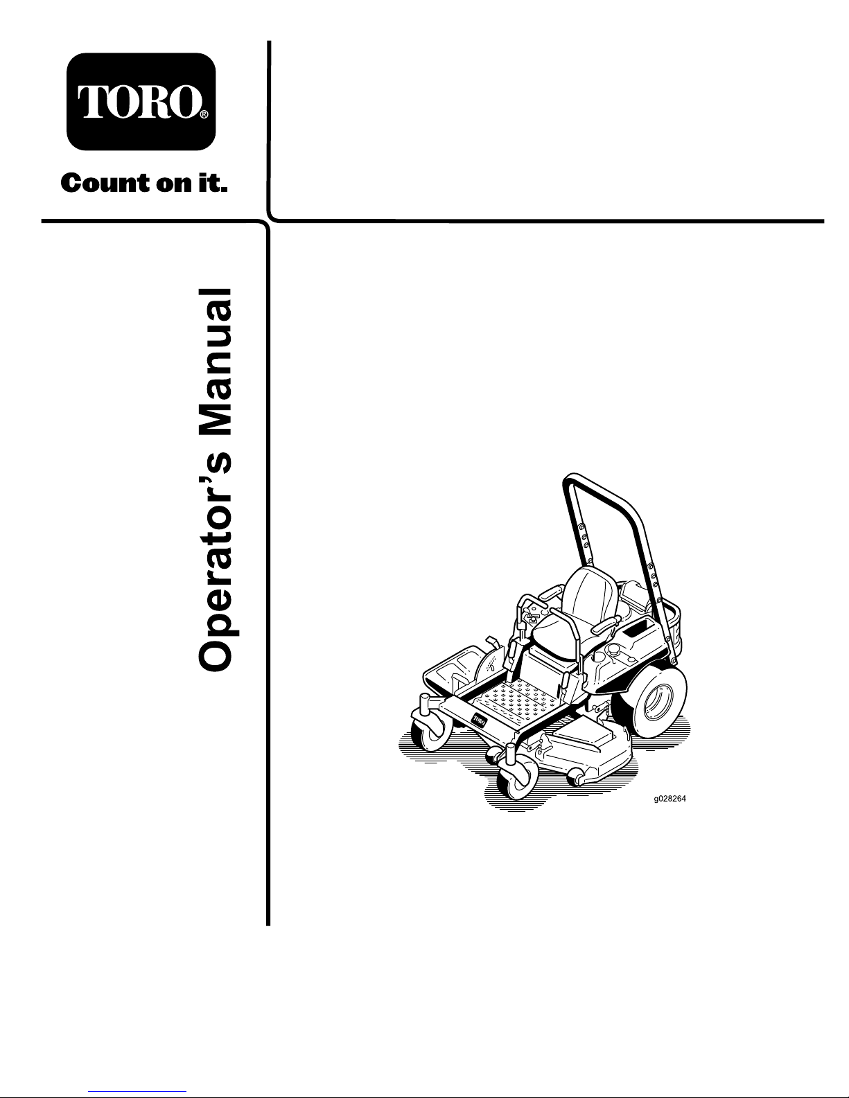
SlopeIndicator
G011841
Figure3
Thispagemaybecopiedforpersonaluse.
1.Themaximumslopeyoucansafelyoperatethemachineonis15degrees.Usetheslopecharttodeterminethedegreeofslope
ofhillsbeforeoperating.Donotoperatethismachineonaslopegreaterthan15degrees.Foldalongtheappropriateline
tomatchtherecommendedslope.
2.Alignthisedgewithaverticalsurface,atree,building,fencepole,etc.
3.Exampleofhowtocompareslopewithfoldededge.
7
Page 8
SafetyandInstructionalDecals
Safetydecalsandinstructionsareeasilyvisibletotheoperatorandarelocatednearanyareaofpotential
danger.Replaceanydecalthatisdamagedorlost.
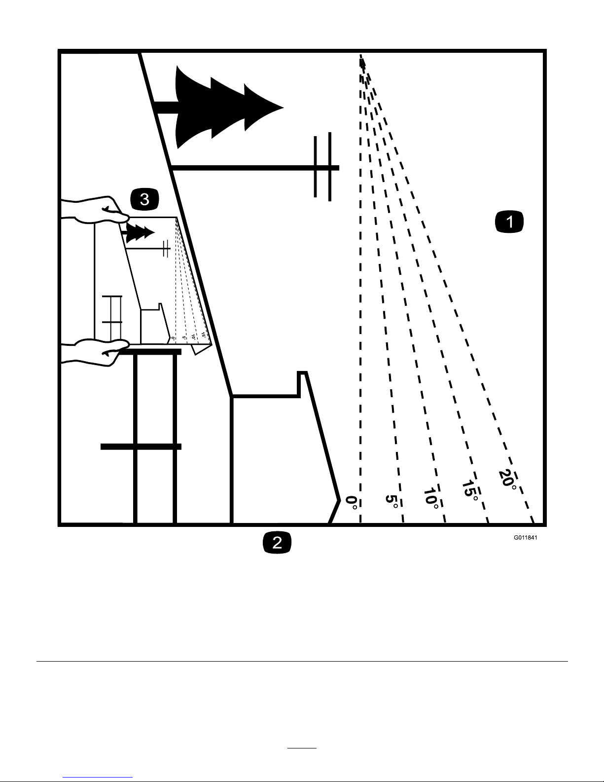
1-653558
99-8936
1.Machinespeed4.Neutral
2.Fast5.Reverse
3.Slow
Manufacturer'sMark
1.Indicatesthebladeisidentiedasapartfromtheoriginal
machinemanufacturer.
110-6691
1.Thrownobjecthazard—keepbystandersasafedistance
fromthemachine.
2.Thrownobjecthazard,mower—donotoperatewithoutthe
deector,dischargecover,orgrasscollectionsystemin
place.
3.Cutting/dismembermentofhandorfoot—stayawayfrom
movingparts.
114-1606
1.Entanglementhazard,belt—keepallguardsinplace.
115-9625
1.Parking
brake—disengaged
2.Parkingbrake—engaged
8
Page 9
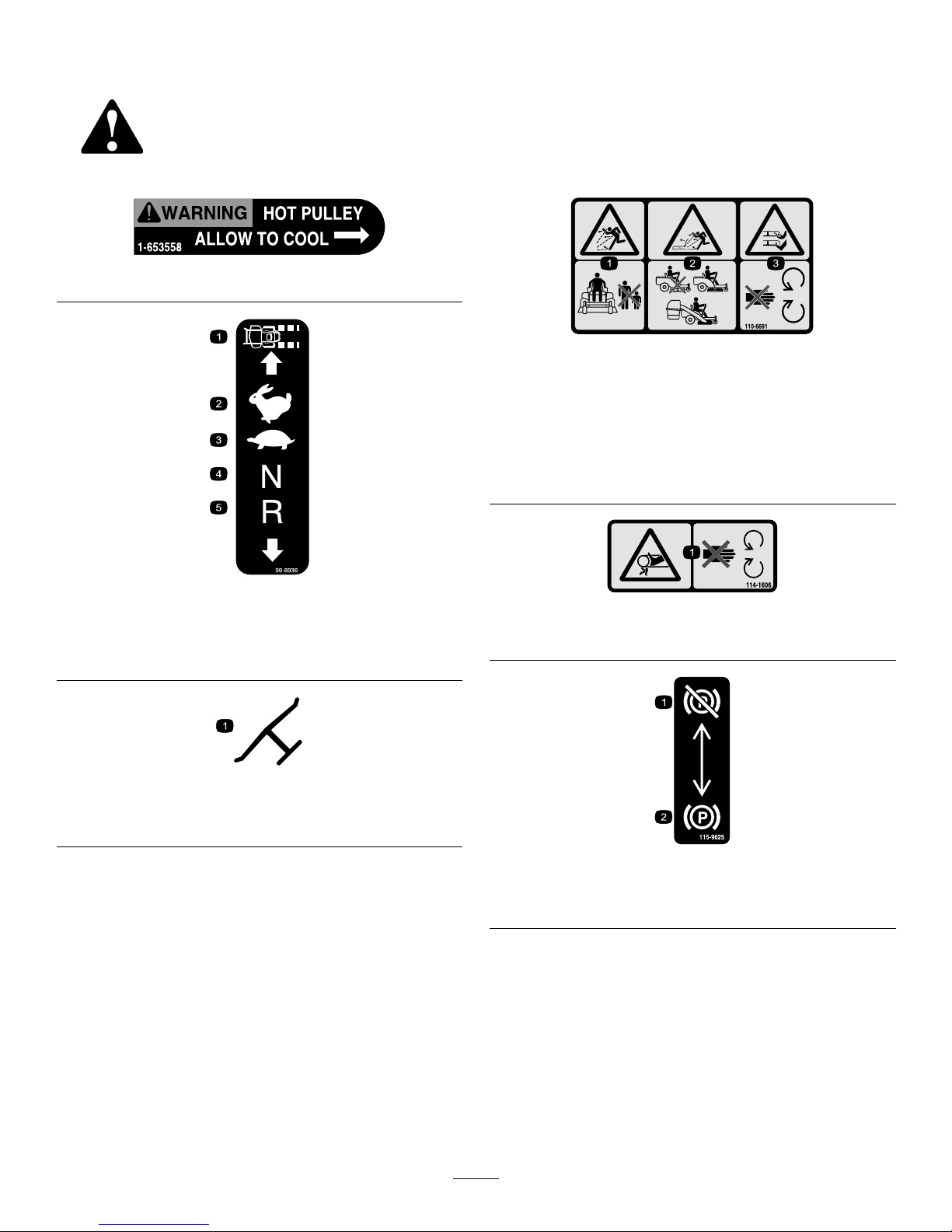
115-9632
1.Powertake-off(PTO),
Bladecontrolswitchon
somemodels
5.Fast
2.Bladecontrolswitch—On6.Continuousvariable
setting
3.Bladecontrolswitch—Off7.Slow
4.Choke
BatterySymbols
Someorallofthesesymbolsareonyourbattery
1.Explosionhazard
6.Keepbystandersasafe
distancefromthebattery.
2.Nore,opename,or
smoking.
7.Weareyeprotection;
explosivegasescan
causeblindnessandother
injuries
3.Causticliquid/chemical
burnhazard
8.Batteryacidcancause
blindnessorsevereburns.
4.Weareyeprotection9.Flusheyesimmediately
withwaterandgetmedical
helpfast.
5.ReadtheOperator's
Manual.
10.Containslead;donot
discard.
117-1194
1.Engine
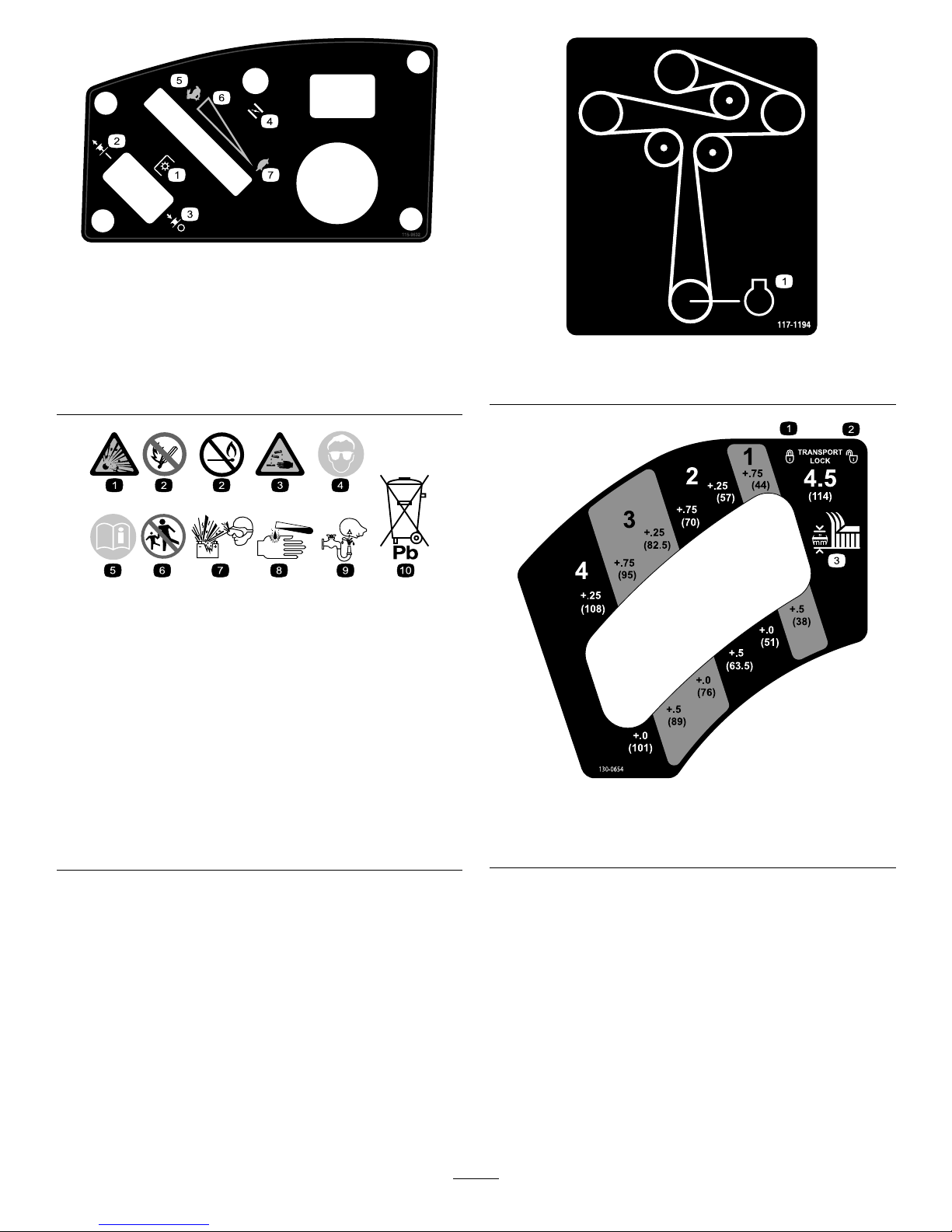
130-0654
1.Transport—lock
3.Height-of-cut
2.Transport—unlock
9
Page 10
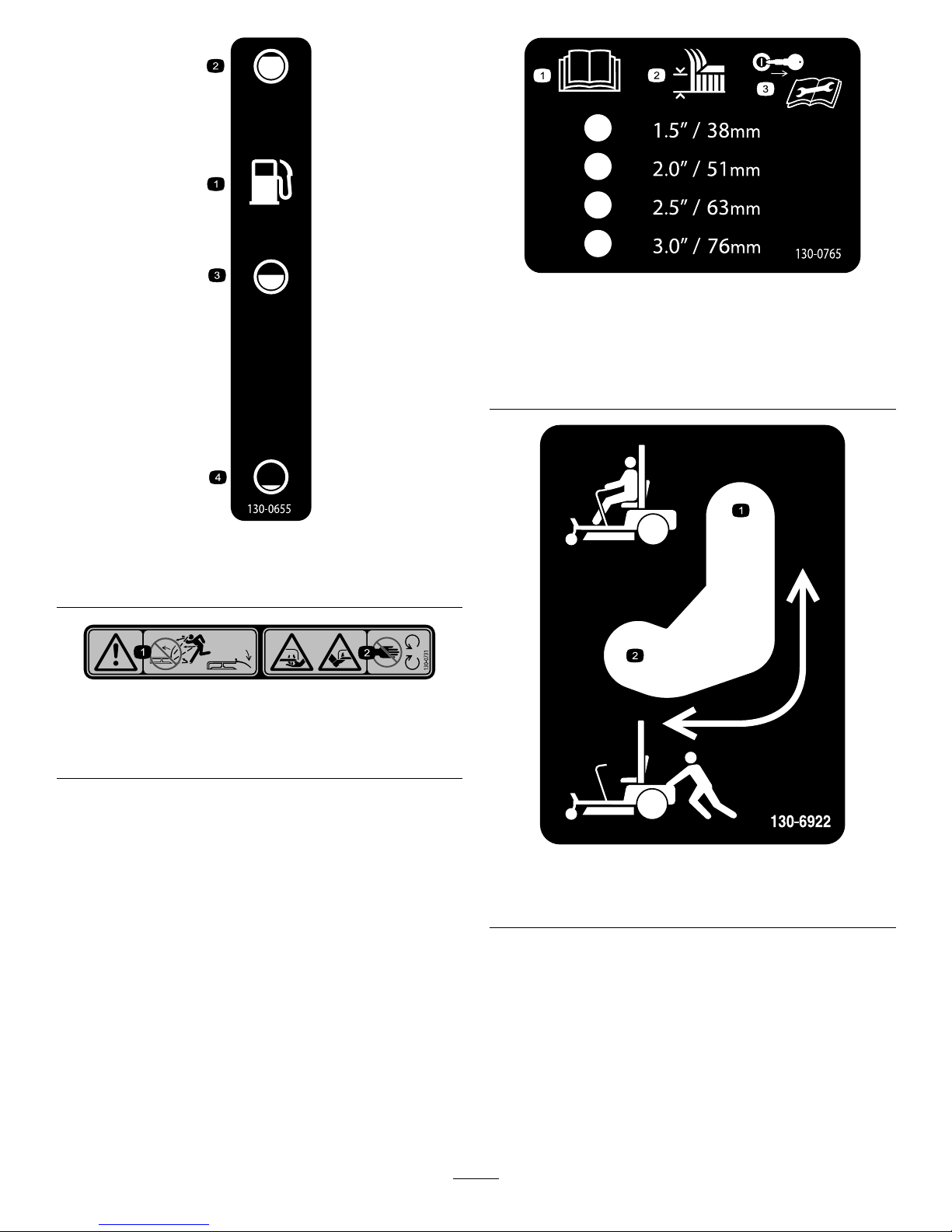
130-0655
1.Fueltank
3.Half
2.Full4.Empty
130-0731
1.Warning—thrownobject
hazard;keepthedeector
shieldinplace.
2.Cuttinghazardofhandor
foot,mowerblade—keep
awayfrommovingparts.
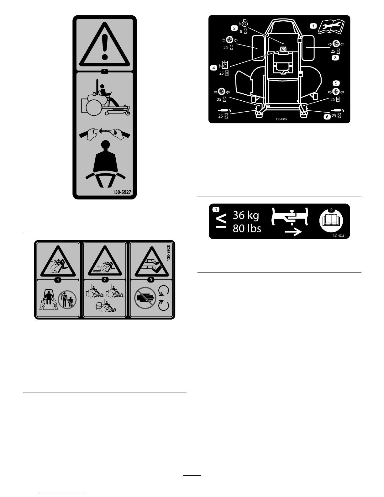
130-0765
1.ReadtheOperator's
Manual.
3.Removethekeyfrom
theignitionandreadthe
Operator'sManualbefore
performingmaintenance.
2.Height-of-cutselection
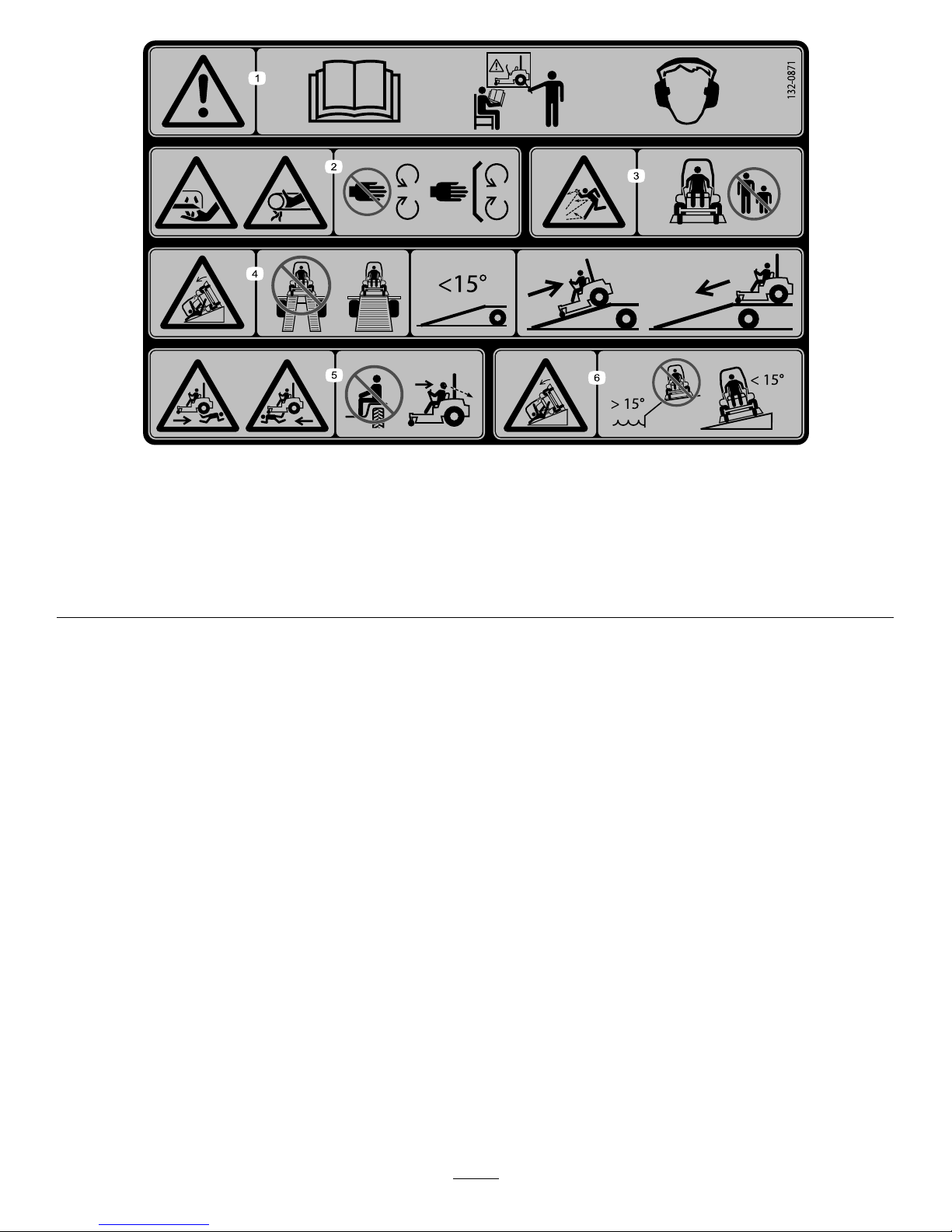
130-6922
1.Bypassleverpositionfor
operatingthemachine.
2.Bypassleverpositionfor
pushingthemachine.
10
Page 11
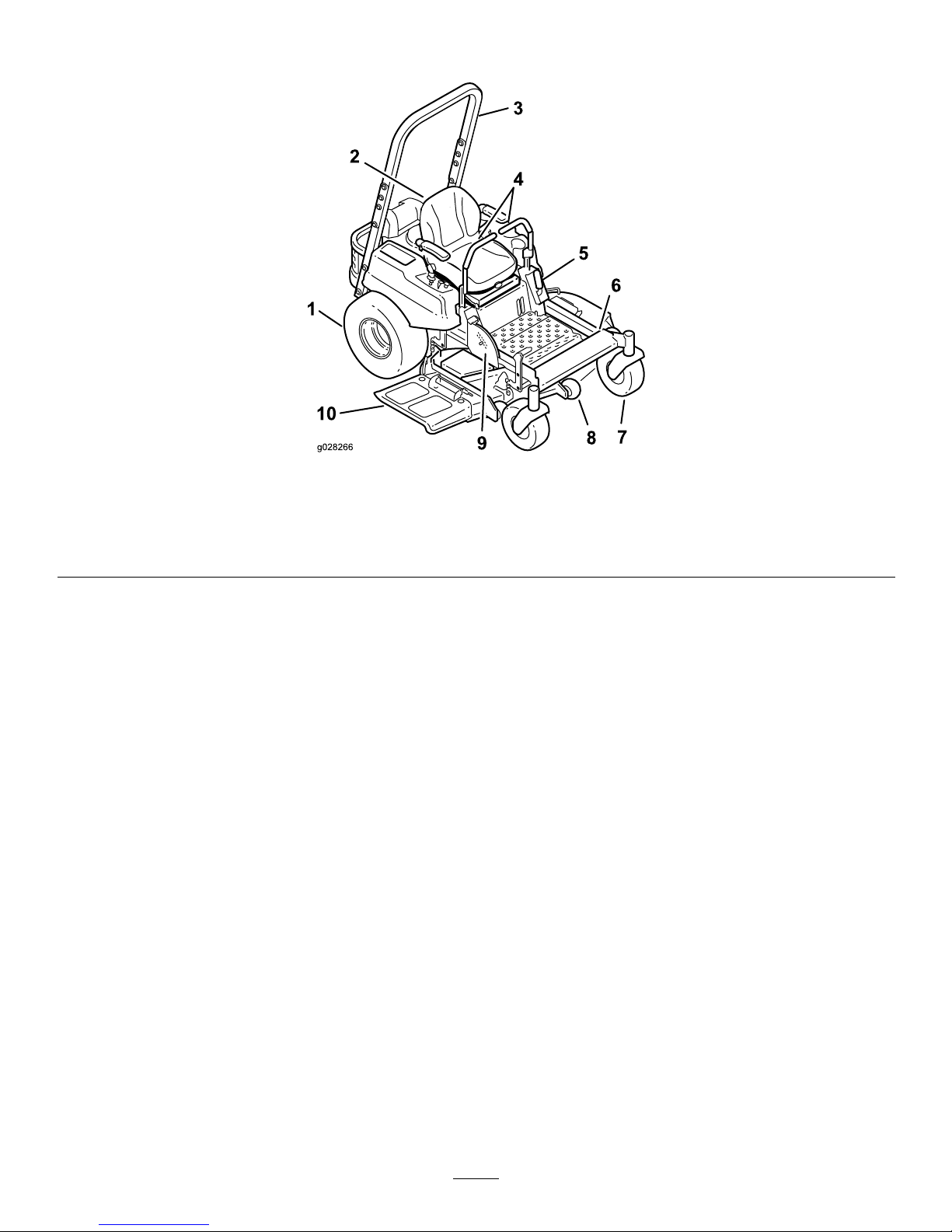
130-6927
1.Warning—alwaysusetheROPSandweartheseatbelt
whenseatedintheoperator'sposition.
130-6928
1.Thrownobject
hazard—keepbystanders
awayfromthemachine.
3.Cutting/dismembermentof
handorfoot—stayaway
frommovingparts.
2.Thrownobjecthazard,
machine—donotoperate
thewithoutdeector,
dischargecover,orgrass
collectionsysteminplace.
130-6996
1.ReadtheOperator's
Manualforinformationon
maintenance.
4.Checkthehydraulicoil
every25hours
2.Checktheengineoilevery
8hours
5.Checkthecasterwheel
tirepressureevery25
hours
3.Checkthedrivewheeltire
pressureevery25hours
6.Lubricatethecasterwheel
every25hours
131-4036
1.Maximumdrawbarpull80
lbs(36kg)
2.ReadtheOperator's
Manual.
11
Page 12
132–0871
1.Warning—readtheOperator’sManual;donotoperatethis
vehicleunlessyouaretrained;wearhearingprotection.
4.Ramphazard—whenloadingontoatrailer,donotusedual
ramps;onlyuseasingularrampwideenoughforthemachine;
backuptheramp(inreverse)anddriveforwardofftheramp.
2.Cuttingandpinchinghazard—keephandsandfeetawayfrom
movingparts;keepallguardsandshieldsinplace.
5.Bodilyharmhazard—lookbehindyouwhenmowingin
reverse.
3.Thrownobjecthazard—keepbystandersaway .6.Tippinghazardonslopes—donotuseonslopesnearopen
water;donotuseonslopesgreaterthan15degrees.
12
Page 13
ProductOverview
Figure4
1.Drivewheel4.Motion-controllevers7.Frontcasterwheel
10.Deector
2.Operatorseat
5.Parkingbrake8.Anti-scalproller
3.Rolloverprotectionsystem
(ROPS)
6.Footrest
9.Footpedaldeckliftand
height-of-cut
13
Page 14
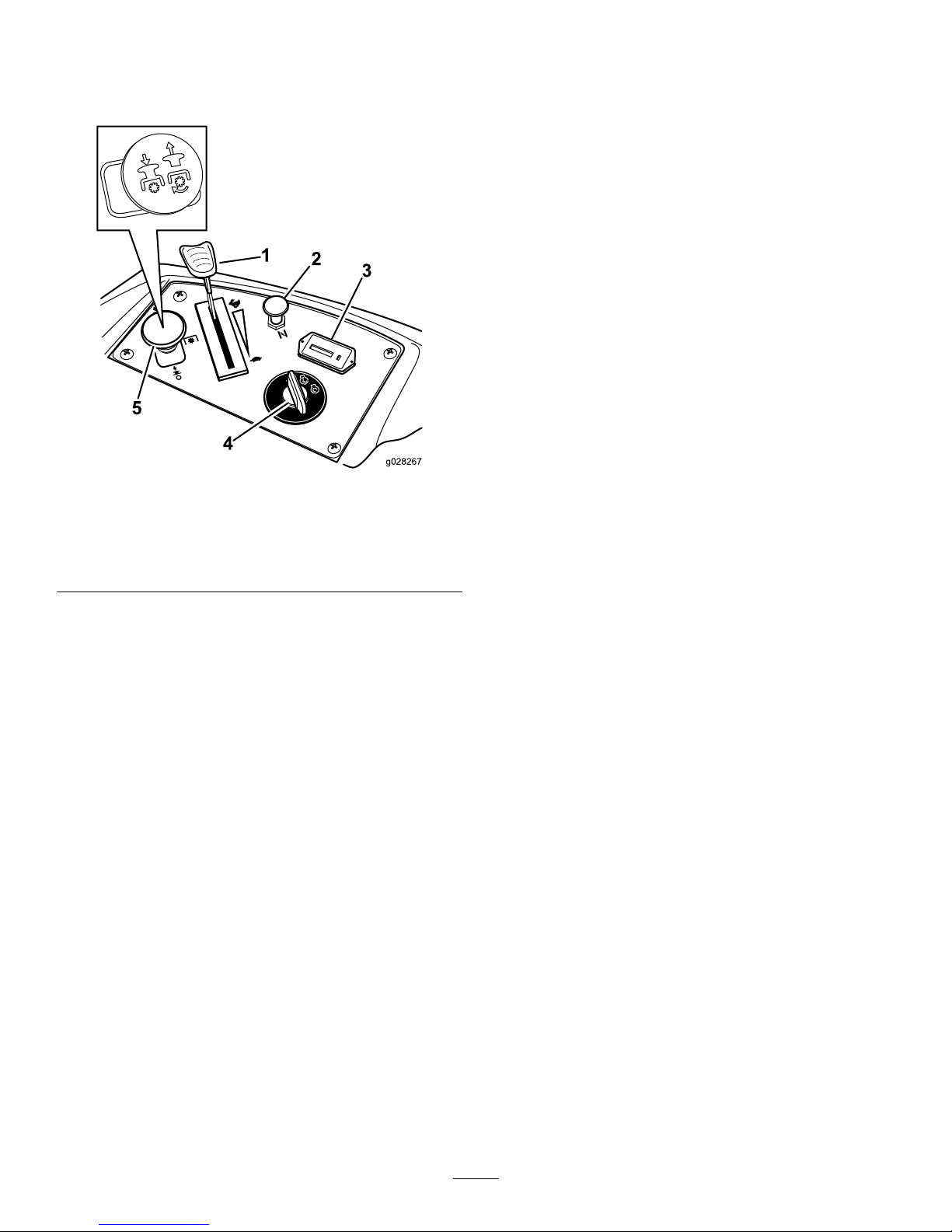
Controls
Becomefamiliarwithallthecontrolsbeforeyoustartthe
engineandoperatethemachine(Figure5).
Figure5
1.Throttlecontrol4.Ignitionswitch
2.Choke
5.Blade-controlswitch
(PTO)
3.Hourmeter
IgnitionSwitch
Theignitionswitchhasthreepositions:Start,RunandOff.
ThekeywillturntoStartandmovebacktoRunuponrelease.
TurningthekeytotheOffpositionwillstoptheengine;
however,alwaysremovethekeywhenleavingthemachineto
preventtheenginefromaccidentallystarting(Figure5).
ThrottleControl
ThethrottlecontrolisvariablebetweenFastandSlow.
Movingthrottleleverforwardwillincreaseenginespeedand
movingthrottlelevertotherearwilldecreaseenginespeed.
Movingthethrottleforwardintothedetentisfullthrottle
(Figure5).
Choke
Usethechoketostartacoldengine.Pullthechokeknobup
toengageit.Pushdownonthechokeknobtodisengageit.
Blade-ControlSwitch(PowerTake-Off)
Theblade-controlswitch,representedbyapowertake-off
(PTO)symbol,engagesanddisengagespowertothemower
blades(Figure5).
HourMeter
Thehourmeterrecordsthenumberofhoursthebladeshave
operated.Itoperateswhentheblade-controlswitch(PTO)is
engaged.Usethesetimesforschedulingregularmaintenance
(Figure5).
FuelGauge
Thefuelwindowlocatedbelowtheoperatorpositioncanbe
usedtoverifythelevelofgasolineinthetank(Figure6).
Motion-ControlLevers
Themotion-controlleversarespeedsensitivecontrolsof
independentwheelmotors.Movingaleverforwardor
backwardturnsthewheelonthesamesideforwardorin
reverse;wheelspeedisproportionaltotheamountthelever
ismoved.Movethecontrolleversoutwardfromthecenter
totheneutral-lockpositionandbeforeexitingthemachine
(Figure4).Alwayspositionthemotion-controlleversintothe
neutral-lockpositionwhenyoustopthemachineorleave
itunattended.
Parking-BrakeLever
Theparkingbrakeleverislocatedonleftsideoftheconsole
(Figure4).Thebrakeleverengagesaparkingbrakeonthe
drivewheels.Pulltheleverupandrearwardtoengagethe
brake.Pushtheleverforwardanddowntodisengagethe
brake.
FootPedalDeckLiftSystem
Thefootpedaldeckliftsystemallowstheoperatortolower
andraisethedeckfromtheseatedposition.Theoperatorcan
usethefootpedaltoliftthedeckbrieytoavoidobstacles
orlockthedeckinthehighestheight-of-cutortransport
position(Figure4).
Height-of-CutLever
Theheight-of-cutleverworkswiththefootpedaltolockthe
deckinaspeciccuttingheight.Onlyadjusttheheightofcut
whilemachineisnotmoving(Figure4).
Attachments/Accessories
AselectionofToroapprovedattachmentsandaccessoriesis
availableforusewiththemachinetoenhanceandexpand
itscapabilities.ContactyourAuthorizedServiceDealeror
Distributororgotowww .Toro.comforalistofallapproved
attachmentsandaccessories.
14
Page 15

Operation
Note:Determinetheleftandrightsidesofthemachine
fromthenormaloperatingposition.
AddingFuel
•Forbestresults,useonlyclean,fresh(lessthan30days
old),unleadedgasolinewithanoctaneratingof87or
higher((R+M)/2ratingmethod).
•Ethanol:Gasolinewithupto10%ethanol(gasohol)
or15%MTBE(methyltertiarybutylether)byvolume
isacceptable.EthanolandMTBEarenotthesame.
Gasolinewith15%ethanol(E15)byvolumeisnot
approvedforuse.Neverusegasolinethatcontains
morethan10%ethanolbyvolume,suchasE15
(contains15%ethanol),E20(contains20%ethanol),or
E85(containsupto85%ethanol).Usingunapproved
gasolinemaycauseperformanceproblemsand/orengine
damagewhichmaynotbecoveredunderwarranty.
•Donotusegasolinecontainingmethanol.
•Donotstorefueleitherinthefueltankorfuelcontainers
overthewinterunlessafuelstabilizerisused.
•Donotaddoiltogasoline.
DANGER
Incertainconditions,gasolineisextremely
ammableandhighlyexplosive.Areorexplosion
fromgasolinecanburnyouandothersandcan
damageproperty.
•Fillthefueltankoutdoors,inanopenarea,
whentheengineiscold.Wipeupanygasoline
thatspills.
•Neverllthefueltankinsideanenclosedtrailer.
•Donotllthefueltankcompletelyfull.Add
gasolinetothefueltankuntilthelevelis6to13
mm(1/4to1/2inch)belowthebottomofthe
llerneck.Thisemptyspaceinthetankallows
gasolinetoexpand.
•Neversmokewhenhandlinggasoline,andstay
awayfromanopenameorwheregasoline
fumesmaybeignitedbyaspark.
•Storegasolineinanapprovedcontainerand
keepitoutofthereachofchildren.Neverbuy
morethana30-daysupplyofgasoline.
•Donotoperatewithoutentireexhaustsystemin
placeandinproperworkingcondition.
DANGER
Incertainconditionsduringfueling,static
electricitycanbereleasedcausingasparkwhich
canignitethegasolinevapors.Areorexplosion
fromgasolinecanburnyouandothersandcan
damageproperty.
•Alwaysplacegasolinecontainersontheground
awayfromyourvehiclebeforelling .
•Donotllgasolinecontainersinsideavehicleor
onatruckortrailerbedbecauseinteriorcarpets
orplastictruckbedlinersmayinsulatethe
containerandslowthelossofanystaticcharge.
•Whenpractical,removegas-poweredequipment
fromthetruckortrailerandrefueltheequipment
withitswheelsontheground.
•Ifthisisnotpossible,thenrefuelsuch
equipmentonatruckortrailerfromaportable
container,ratherthanfromagasolinedispenser
nozzle.
•Ifagasolinedispensernozzlemustbeused,
keepthenozzleincontactwiththerimofthe
fueltankorcontaineropeningatalltimesuntil
fuelingiscomplete.
WARNING
Gasolineisharmfulorfatalifswallowed.Long-term
exposuretovaporscancauseseriousinjuryand
illness.
•Avoidprolongedbreathingofvapors.
•Keepfaceawayfromnozzleandgastankor
conditioneropening.
•Keepgasawayfromeyesandskin.
UsingStabilizer/Conditioner
Useafuelstabilizer/conditionerinthemachinetoprovide
thefollowingbenets:
•Fuelstabilizer/conditionerkeepsgasolinefreshduring
storageof90daysorless.Whenstoringthemachinefor
longerperiods,drainthefuelsystem.
•Itcleanstheenginewhileitruns
•Iteliminatesgum-likevarnishbuildupinthefuelsystem,
whichcauseshardstarting
Important:Donotusefueladditivescontaining
methanolorethanol.
Addthecorrectamountofgasstabilizer/conditionertothe
gas.
Note:Afuelstabilizer/conditionerismosteffectivewhen
mixedwithfreshgasoline.Tominimizethechanceofvarnish
depositsinthefuelsystem,usefuelstabilizeratalltimes.
15
Page 16
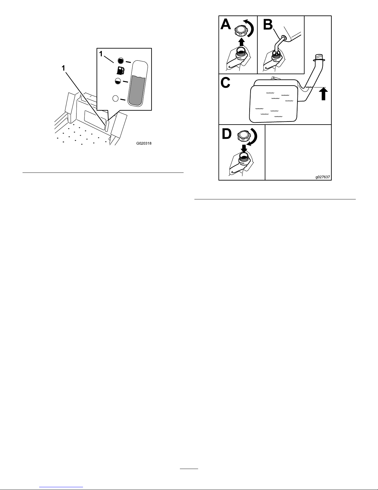
UsingtheFuelGauge
Usethefuelwindowbelowtheoperatortoverifythelevelof
gasolinebeforellingthetank(Figure6).
G020318
1
1
Figure6
1.Fuelgaugewindow
FillingtheFuelTank
Makesuretheengineisshutoffandthemotioncontrolsare
intheparkposition.
Important:Donotoverllfueltank.Fillthefueltank
tothebottomofthellerneck.Theemptyspaceinthe
tankallowsthefueltoexpand.Overllingmayresultin
fuelleakageordamagetotheengineoremissionsystem.
1.Cleanaroundthefueltankcapandremovethecap.
Note:Youcanusethefuelwindowbelowthe
operatingpositionverifythepresenceofgasoline
beforellingthetank(Figure6).
2.Slowlyaddregular,unleadedgasolineuntilthefuel
reachesthebaseofthellerneckFigure7.
B
A
C
D
g027637
Figure7
3.Installthefueltankcapsecurelyandtightenuntilit
“clicks.”Wipeupanygasolinethatmayhavespilled.
CheckingtheEngine-OilLevel
Beforeyoustarttheengineandusethemachine,check
theoillevelintheenginecrankcase;refertoCheckingthe
Engine-OilLevel(page31).
16
Page 17
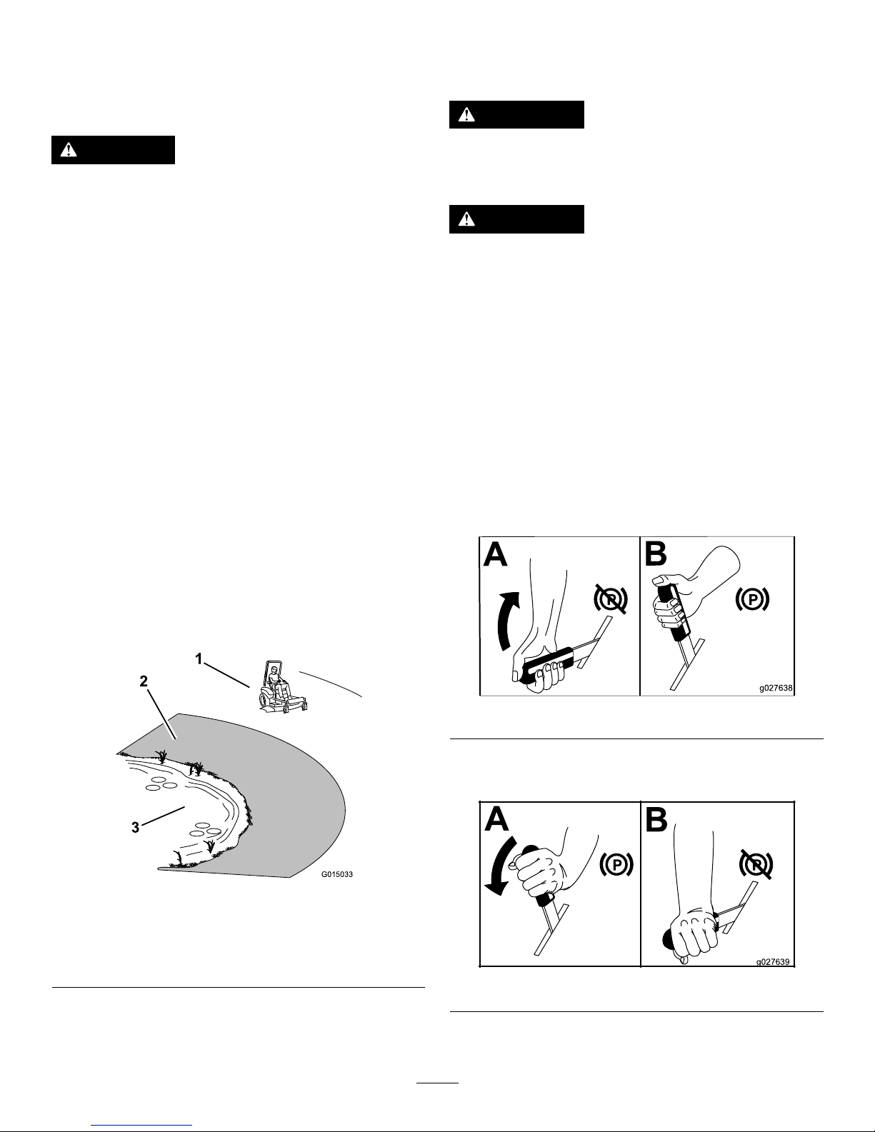
ThinkSafetyFirst
Pleasecarefullyreadallofthesafetyinstructionsanddecals
inthesafetysection.Knowingthisinformationcouldhelp
you,yourfamily ,petsorbystandersavoidinjury.
DANGER
Mowingonwetgrassorsteepslopescancause
slidingandlossofcontrol.
Wheelsdroppingoveredgescancauserollovers,
whichmayresultinseriousinjury,deathor
drowning.
Alossoftractionisalossofsteeringcontrol.
Toavoidlossofcontrolandpossibilityofrollover:
•Donotmowneardrop-offsornearwater.
•Donotmowslopesgreaterthan15degrees.
•Reducespeedanduseextremecautionon
slopes.
•Whenmowingslopes,graduallyworkfrom
lowertohigherareasontheincline.
•Avoidsuddenturnsorrapidspeedchanges.
•Turnup,intoaninclinewhenchanging
directionsonslopes.Turningdowntheslope
reducestraction.
•Attachmentschangethehandlingcharacteristics
ofthemachine.Useextracautionwhenusing
attachmentswiththemachine.
G015033
1
2
3
Figure8
1.SafeZone-usethemachinehere
2.Usewalkbehindmowerand/orhandtrimmerneardrop-offs
andwater .
3.Water
UsingtheRolloverProtection
System(ROPS)
WARNING
Toavoidinjuryordeathfromrollover:keeptheroll
barinstalledandusetheseatbelt.
WARNING
Thereisnorolloverprotectionwhentherollbaris
removed.
•Driveslowlyandcarefully.
•Checkcarefullyforoverheadclearances(i.e.
branches,doorways,electricalwires)before
drivingunderanyobjectsanddonotcontact
them.
OperatingtheParkingBrake
Alwayssettheparkingbrakewhenyoustopthemachineor
leaveitunattended.
SettingtheParkingBrake
B
A
g027638
Figure9
ReleasingtheParkingBrake
B
A
g027639
Figure10
17
Page 18

OperatingtheThrottle
ThethrottlecontrolcanbemovedbetweenFastandSlow
positions(Figure11).
Alwaysusethefastpositionwhenturningonthemowerdeck
withtheblade-controlswitch(PTO).
g028222
Figure11
OperatingtheChoke
Usethechoketostartacoldengine.
1.Pulluponthechokeknobtoengagethechokebefore
usingtheignitionswitch(Figure12).
2.Pushdownonthechoketodisengagethechokeafter
theenginehasstarted(Figure12).
G008959
1
2
Figure12
1.On2.Off
OperatingtheIgnitionSwitch
1.TurntheignitionkeytotheStartposition(Figure13).
Whentheenginesstarts,releasethekey .
Important:Donotengagestarterformorethan5
secondsatatime.Iftheenginefailstostartallow
a15secondcool-downperiodbetweenattempts.
Failuretofollowtheseinstructionscanburnout
thestartermotor.
Note:Additionalstartingcyclesmayberequired
whenstartingtheengineforthersttimeafterthefuel
systemhasbeenwithoutfuelcompletely.
START
RUN
STOP
G008947
Figure13
2.Tostoptheengine,turntheignitionkeytothestop
position.
StartingandStoppingthe
Engine
StartingtheEngine
Note:Awarmorhotenginemaynotrequirechoking
(Figure14).
Important:Donotengagestarterformorethan5
secondsatatime.Iftheenginefailstostartallowa15
secondcool-downperiodbetweenattempts.Failureto
followtheseinstructionscanburnoutthestartermotor.
Note:Ifthefuelsystemwasdepletedoffuel—addfuelto
themachineanduseadditionalstartingcycleswhenstarting
theengine.
18
Page 19

g028223
B
A
D
C
F
E
S
T
A
R
T
R
U
N
S
T
O
P
H
G
Figure14
StoppingtheEngine
CAUTION
Childrenorbystanderscanbeinjuredifthey
moveorattempttooperatethemachinewhileitis
unattended.
Alwaysremovetheignitionkeyandsettheparking
brakewhenleavingthemachineunattended,even
ifjustforafewminutes.
BA
DC
E
S
T
A
R
T
R
U
N
S
T
O
P
g028224
Figure15
OperatingtheMower
Blade-ControlSwitch(PTO)
Theblade-controlswitch(PTO)startsandstopsthemower
bladesandanypoweredattachments.
EngagingtheBlade-ControlSwitch
(PTO)
Engagetheblade-controlswitch(PTO)withthethrottle
positionatFast.
Note:Engagingtheblade-controlswitch(PTO)withthe
throttlepositionathalforlesswillcauseexcessivewearto
thedrivebelts.
G008945
Figure16
19
Page 20

DisengagingtheBlade-ControlSwitch
(PTO)
G009174
Figure17
TheSafety-InterlockSystem
WARNING
Ifsafety-interlockswitchesaredisconnectedor
damagedthemachinecouldoperateunexpectedly
causingpersonalinjury.
•Donottamperwiththeinterlockswitches.
•Checktheoperationoftheinterlockswitches
dailyandreplaceanydamagedswitchesbefore
operatingthemachine.
UnderstandingtheSafety-Interlock
System
Thesafety-interlocksystemisdesignedtopreventtheengine
fromstartingunless:
•Theparkingbrakeisengaged.
•Thebladesaredisengaged.
•Themotion-controlleversareintheneutral-lockposition.
Thesafety-interlocksystemalsoisdesignedtostoptheengine
whenthecontrolleversareoutoftheneutral-lockposition
withtheparkingbrakeonorifyourisefromtheseatwhen
thebladesareengaged.
TestingtheSafety-InterlockSystem
Testthesafety-interlocksystembeforeyouusethemachine
eachtime.Ifthesafetysystemdoesnotoperateasdescribed
below,haveanAuthorizedServiceDealerrepairthesafety
systemimmediately.
1.Whilesittingontheseat,engagetheparkingbrakeand
movetheblade-controlswitchtoOn.Trystartingthe
engine;theengineshouldnotcrank.
2.Whilesittingontheseat,engagetheparkingbrakeand
movetheblade-controlswitchtoOff.Moveeither
motion-controllever(forwardorreverse).Trystarting
theengine;theengineshouldnotcrank.Repeatwith
theothermotion-controllever.
3.Whilesittingontheseat,engagetheparkingbrake,
movetheblade-controlswitchtoOff,andlockthe
motion-controlleversinneutral.Starttheengine.
Whiletheengineisrunning,releasetheparkingbrake,
engagetheblade-controlswitch,andriseslightlyfrom
theseat;theengineshouldstop.
4.Whilesittingontheseat,engagetheparkingbrake,
movetheblade-controlswitchtoOff,andlockthe
motion-controlleversinneutral.Starttheengine.
Whiletheengineisrunning,centerthemotion
controls;theengineshouldstop.
DrivingForwardorBackward
Thethrottlecontrolregulatestheenginespeedasmeasured
inrpm(revolutionsperminute).Placethethrottlecontrolin
thefastpositionforbestperformance.Alwaysoperateinthe
fullthrottlepositionwhenmowing.
CAUTION
Machinecanspinveryrapidly.Operatormaylose
controlofmachineandcausepersonalinjuryor
damagetomachine.
•Usecautionwhenmakingturns.
•Slowthemachinedownbeforemakingsharp
turns.
20
Page 21

UsingtheMotion-ControlLevers
Figure18
1.Motion-control
lever—neutral-lock
position
4.Backward
2.Center,unlockedposition5.Frontofmachine
3.Forward
DrivingForward
Note:Theenginewillkillifthetractioncontrolleversare
movedwiththeparkingbrakeengaged.
1.Releasetheparkingbrake;refertoReleasingthe
ParkingBrake(page17).
2.Movetheleverstothecenter,unlockedposition.
3.Togoforward,slowlypushthemotion-controllevers
forward(Figure19).
G008952
Figure19
DrivingBackward
1.Movetheleverstothecenter,unlockedposition.
2.Togobackward,slowlypullthemotion-controllevers
rearward(Figure20).
G008953
Figure20
21
Page 22

StoppingtheMachine
Tostopthemachine,movethetractioncontrollevers
toneutralandmovetolockedposition,disengagethe
blade-controlswitch(PTO),andturntheignitionkeytooff.
Settheparkingbrakewhenyouleavethemachine;referto
OperatingtheParkingBrake(page17).Remembertoremove
thekeyfromtheignitionswitch(Figure15).
CAUTION
Childrenorbystandersmaybeinjuredifthey
moveorattempttooperatethemachinewhileitis
unattended.
Alwaysremovetheignitionkeyandsettheparking
brakewhenleavingthemachineunattended,even
ifjustforafewminutes.
AdjustingtheHeight-of-Cut
Themachineisequippedwithafootpedaldeckliftsystem.
Theoperatorcanusethefootpedaltoliftthedeckbrieyto
avoidobstaclesorlockthedeckinthehighestheight-of-cut
ortransportposition.Theoperatorcanusetheheightof
cutleverwiththefootpedaltolockthedeckinaspecic
cuttingheight.
UsingtheFootPedalDeckLiftSystem
•Pressthepedaldowntoraisethedeck;continuetopress
thepedaluntilthedeckislockedinthetransportposition
(Figure21).
•Pushonthedeckliftpedalwithyourfootandpullthe
transportlockhandlerearwardtodisengagethetransport
lock(Figure21).
g024409
Figure21
TransportLockPosition
AdjustingtheHeight-of-Cut
Theheight-of-cutcanbeadjustedfrom38to114mm(1-1/2
to4-1/2inch)in6mm(1/4inch)incrementsbyrelocating
theheight-of-cutpinintodifferentholelocations.
1.Pushonthedeckliftpedalwithyourfootandraisethe
mowerdecktothetransportlockposition(alsothe
114mm(4-1/2inch)cuttingheightposition)(Figure
22).
2.Toadjust,removethepinfromtheheight-of-cut
bracket(Figure22).
3.Selectaholeintheheight-of-cutsystemcorresponding
totheheight-of-cutdesiredandinsertthepin(Figure
22).
4.Pushonthedeckliftpedalwithyourfootandpull
thehandlerearwardtodisengagethetransportlock
(Figure21).
5.Lowerthedeckslowlyuntilthelevermakescontact
withthepin.
22
Page 23

g024410
1
2
3
4
Figure22
1.Deckliftpedal3.Height-of-cutpositions
2.Handle4.Pin
AdjustingtheAnti-Scalp
Rollers
Wheneveryouchangetheheight-of-cut,itisrecommended
toadjusttheheightoftheanti-scalprollers.
1.Disengagetheblade-controlswitch(PTO),movethe
motion-controlleverstotheneutral-lockpositionand
settheparkingbrake.
2.Stoptheengine,removethekey,andwaitforallmoving
partstostopbeforeleavingtheoperatingposition.
3.Removetheangenut,anti-scalprollerandboltfrom
thebracket(Figure23).
g024312
1
2 3 4
5
Figure23
1.FlangeNut4.Bushing
2.Spacer
5.Bolt
3.Anti-scalproller
4.Aligntheboltandanti-scalprollerintheholeofthe
bracketthatmatchestheclosestheightofcutposition
(Figure23).
5.Inserttheboltintothebracketholeandsecurethebolt
andanti-scalprollerwiththeangenut(Figure23).
PositioningtheSeat
Theseatcanmoveforwardandbackward.Positiontheseat
whereyouhavethebestcontrolofthemachineandaremost
comfortable.
Figure24
ChangingtheSeatSuspension
Theseatisadjustabletoprovideasmoothandcomfortable
ride.Positiontheseatwhereyouaremostcomfortable.
Toadjustit,turntheknobinfronteitherdirectiontoprovide
thebestcomfort(Figure32).
Figure25
1.Seatsuspensionknob
23
Page 24

AdjustingtheMotion-Control
Levers
AdjustingtheHeight
Note:Repeattheadjustmentfortheoppositecontrollever.
Themotion-controlleverscanbeadjustedhigherorlowerfor
maximumoperatorcomfort(Figure26).
g027252
B
A
Figure26
AdjustingtheTilt
Themotion-controlleverscanbetiltedforeoraftfor
maximumoperatorcomfort.
1.Loosentheupperboltholdingthecontrollevertothe
controlarmshaft.
2.Loosenthelowerboltjustenoughtopivotthecontrol
leverforeoraft.Tightenbothboltstosecurethe
controlinthenewposition.
3.Repeattheadjustmentfortheoppositecontrollever.
PushingtheMachinebyHand
Important:Alwayspushthemachinebyhand.Machine
damagecanoccurwhenthemachineistowed.
ToPushtheMachine
1.Parkthemachineonalevelsurfaceanddisengagethe
blade-controlswitch.
2.Engagetheparkingbrake.
3.Movethemotion-controlleversoutwardtoneutral-lock
position,stoptheengine,removethekey ,andwaitfor
allmovingpartstostopbeforeleavingtheoperating
position.
4.Locatethebypassleversattherearofthemachine,on
theleftandrightsideoftheframe.
5.Movethebypassleversrearwardandthendownto
locktheminplaceasshowninFigure27todisengage
thewheelmotors.
Note:Ensurethattheleftandrightbypassleversare
rearwardandlockedbeforemovingthemachine.
6.Disengagetheparkingbrake.
Themachineisnowabletobepushedbyhand.
BA
DC
g027642
Figure27
ToOperatetheMachine
Movethebypasstothepositionforoperatingthemachine
(Figure27)toengagethewheelmotors.
24
Page 25

UsingtheSideDischarge
Themowerhasahingedgrassdeectorthatdisperses
clippingstothesideanddowntowardtheturf.
DANGER
Withoutagrassdeector,dischargecover,or
completegrasscatcherassemblymountedin
place,youandothersareexposedtobladecontact
andthrowndebris.Contactwithrotatingmower
blade(s)andthrowndebriswillcauseinjuryor
death.
•Neverremovethegrassdeectorfromthemower
becausethegrassdeectorroutesmaterialdown
towardtheturf.Ifthegrassdeectorisever
damaged,replaceitimmediately .
•Neverputyourhandsorfeetunderthemower.
•Nevertrytoclearthedischargeareaormower
bladesunlessyoumovetheblade-controlswitch
(PTO)totheoffposition,rotatetheignitionkey
tooffandremovethekey .
•Makesurethegrassdeectorisinthedown
position.
TransportingtheMachine
Useaheavy-dutytrailerortrucktotransportthemachine.
Ensurethatthetrailerortruckhasallnecessarybrakes,
lighting,andmarkingasrequiredbylaw .Pleasecarefullyread
allthesafetyinstructions.Knowingthisinformationcould
helpyou,yourfamily,pets,orbystandersavoidinjury.
WARNING
Drivingonthestreetorroadwaywithoutturn
signals,lights,reectivemarkings,oraslow
movingvehicleemblemisdangerousandcanlead
toaccidentscausingpersonalinjury.
Donotdrivemachineonapublicstreetorroadway.
Totransportthemachine:
1.Ifusingatrailer,connectittothetowingvehicleand
connectthesafetychains.
2.Ifapplicable,connectthetrailerbrakes.
3.Loadthemachineontothetrailerortruck.
4.Stoptheengine,removethekey,setthebrake,and
closethefuelvalve.
5.Tiedownthemachinenearthefrontcasterwheelsand
therearbumper(Figure28).
Figure28
LoadingtheMachine
Useextremecautionwhenloadingorunloadingmachines
ontoatraileroratruck.Useafull-widthrampthatiswider
thanthemachineforthisprocedure.Backuprampsand
driveforwarddownramps(Figure29).
g028043
Figure29
1.Backupramps
2.Driveforwarddownramps
Important:Donotusenarrowindividualrampsfor
eachsideofthemachine.
Ensuretherampislongenoughsothattheanglewiththe
grounddoesnotexceed15degrees(Figure30).Onat
ground,thisrequiresaramptobeatleast4timesaslongas
theheightofthetrailerortruckbedtotheground.Asteeper
anglemaycausemowercomponentstogetcaughtastheunit
movesfromtheramptothetrailerortruck.Steeperangles
mayalsocausethemachinetotiporlosecontrol.Ifloading
onornearaslope,positionthetrailerortrucksothatitis
onthedownsideoftheslopeandtherampextendsupthe
slope.Thiswillminimizetherampangle.
25
Page 26

WARNING
Loadingamachineontoatrailerortruckincreases
thepossibilityoftip-overandcouldcauseserious
injuryordeath.
•Useextremecautionwhenoperatingamachine
onaramp.
•EnsurethattheROPSisintheuppositionand
usetheseatbeltwhenloadingorunloadingthe
machine.EnsurethattheROPSwillclearthe
topofanenclosedtrailer.
•Useonlyafull-widthramp;donotuseindividual
rampsforeachsideofthemachine.
•Donotexceeda15-degreeanglebetweenthe
rampandthegroundorbetweentherampand
thetrailerortruck.
•Ensurethelengthoframpisatleastfourtimes
(4X)aslongastheheightofthetrailerortruck
bedtotheground.Thiswillensurethatramp
angledoesnotexceed15degreesonatground.
•Backuprampsanddriveforwarddownramps.
•Avoidsuddenaccelerationordecelerationwhile
drivingthemachineonarampasthiscould
causealossofcontroloratip-oversituation.
g027996
5
1
2
6
Figure30
1.Full-widthrampinstowed
position
4.Rampisatleast4times
aslongastheheightof
thetrailerortruckbedto
theground
2.Sideviewoffull-width
rampinloadingposition
5.H=heightofthetraileror
truckbedtotheground
3.Notgreaterthan
15degrees
6.Trailer
26
Page 27

OperatingTips
FastThrottleSetting
Forbestmowingandmaximumaircirculation,operate
theengineatthefastthrottleposition.Airisrequiredto
thoroughlycutgrassclippings,sodonotsettheheight-of-cut
solowastototallysurroundthemowerbyuncutgrass.
Alwaystrytohaveonesideofthemowerfreefromuncut
grass,whichallowsairtobedrawnintothemower.
CuttingaLawnfortheFirstTime
Cutgrassslightlylongerthannormaltoensurethecutting
heightofthemowerdoesnotscalpanyunevenground.
However,thecuttingheightusedinthepastisgenerallythe
bestonetouse.Whencuttinggrasslongerthan15.24cm(6
inches)tall,youmaywanttocutthelawntwicetoensure
anacceptablequalityofcut.
Cut1/3oftheGrassBlade
Itisbesttocutonlyabout1/3ofthegrassblade.Cutting
morethanthatisnotrecommendedunlessgrassissparse,or
itislatefallwhengrassgrowsmoreslowly.
AlternatingtheMowingDirection
Alternatemowingdirectiontokeepthegrassstanding
straight.Thisalsohelpsdisperseclippingswhichenhances
decompositionandfertilization.
MowingatCorrectIntervals
Normally,moweveryfourdays.Butremember,grassgrows
atdifferentratesatdifferenttimes.Sotomaintainthesame
cuttingheight,whichisagoodpractice,mowmoreoftenin
earlyspring.Asthegrassgrowthrateslowsinmidsummer,
mowlessfrequently.Ifyoucannotmowforanextended
period,rstmowatahighcuttingheight;thenmowagain
twodayslateratalowerheightsetting.
CuttingSpeed
Toimprovecutquality,useaslowergroundspeedincertain
conditions.
AvoidCuttingTooLow
Ifthecuttingwidthofthemoweriswiderthanthemower
youpreviouslyused,raisethecuttingheighttoensurethat
uneventurfisnotcuttooshort.
CuttingLongGrass
Ifthegrassiseverallowedtogrowslightlylongerthan
normal,orifitcontainsahighdegreeofmoisture,raisethe
cuttingheighthigherthanusualandcutthegrassatthis
setting.Thencutthegrassagainusingthelower,normal
setting.
StoppingtheMachine
Ifyoumuststopthemachine'sforwardmotionwhilemowing,
aclumpofgrassclippingsmaydropontoyourlawn.Toavoid
this,moveontoapreviouslycutareawiththebladesengaged.
KeeptheUndersideoftheMowerClean
Cleanclippingsanddirtfromtheundersideofthemower
aftereachuse.Ifgrassanddirtbuildupinsidethemower,
cuttingqualitywilleventuallybecomeunsatisfactory.
MaintainingtheBlade
Maintainasharpbladethroughoutthecuttingseasonbecause
asharpbladecutscleanlywithouttearingorshreddingthe
grassblades.Tearingandshreddingturnsgrassbrownat
theedges,whichslowsgrowthandincreasesthechanceof
disease.Checkthecutterbladesdailyforsharpness,andfor
anywearordamage.Filedownanynicksandsharpenthe
bladesasnecessary.Ifabladeisdamagedorworn,replaceit
immediatelywithagenuineT ororeplacementblade.
27
Page 28

Maintenance
RecommendedMaintenanceSchedule(s)
MaintenanceService
Interval
MaintenanceProcedure
Aftertherst50hours
•Changethehydraulicsystemlterandoil.
Beforeeachuseordaily
•Checkthesafety-interlocksystem.
•Checktheaircleanerfordirty,looseordamagedparts.
•Checktheengine-oillevel.
•Cleantheblowerhousing(moreoftenunderextremelydusty ,dirtyconditions).
•Checkthemowerblades.
•Inspectthegrassdeectorfordamage.
Aftereachuse
•Cleanthemowerhousing.
Every25hours
•Greasealllubricationpoints.
•Serviceorreplacethefoamelement(moreoftenunderextremelydusty ,dirty
conditions).
•Checktirepressure.
•Checkthehydraulicoillevelintheexpansiontank.
Every50hours
•Inspectthebeltsforcracksandwear .
Every100hours
•Replacethepaperelement(moreoftenunderextremelydusty,dirtyconditions).
•Changetheengineoilandtheengine-oillter.
•Cleanthecoolingns(moreoftenunderextremelydusty,dirtyconditions).
•Replacethefuellter(moreoftenunderdusty,dirtyconditions).
Every400hours
•Changethehydraulicsystemlterandoil.
Every500hours
•Replacethesparkplug(s).
Monthly
•Checkthebatterycharge.
Yearlyorbeforestorage
•Paintchippedsurfaces.
•Checkallmaintenanceprocedureslistedabovebeforestorage.
Important:Refertoyourengineoperator'smanualforadditionalmaintenanceprocedures.
CAUTION
Ifyouleavethekeyintheignitionswitch,someonecouldaccidentlystarttheengineandseriouslyinjure
youorotherbystanders.
Removethekeyfromtheignitionanddisconnectthewirefromthesparkplugbeforeyoudoany
maintenance.Setthewireasidesothatitdoesnotaccidentallycontactthesparkplug.
28
Page 29

Figure31
1.ReadtheOperator'sManualforinformationonmaintenance.4.Checkthehydraulicoilevery25hours.
2.Checktheengineoilevery8hours.5.Checkthecasterwheeltirepressureevery25hours.
3.Checkthedrivewheeltirepressureevery25hours.
6.Lubricatethecasterwheelevery25hours.
Premaintenance
Procedures
RaisingtheSeat
Makesurethatthemotion-controlleversaretheneutral-lock
positionandparkingbrakeisset.Liftandholdthelever
behindtheseatforwardtodisengagetheseatlatchandthen
lifttheseatforward.
Thefollowingcomponentscanbeaccessedbyraisingtheseat:
•Servicedecal
•Fuses
•Batteryandcables
Lubrication
GreasingtheBearings
ServiceInterval:Every25hours—Greasealllubrication
points.
GreaseType:No.2general-purpose,lithium-basedgrease
1.Parkthemachineonalevelsurfaceanddisengagethe
blade-controlswitch.
2.Movethemotion-controlleversoutwardtotheneutral
position,settheparkingbrake,stoptheengine,remove
thekey ,andwaitforallmovingpartstostopbefore
leavingtheoperatingposition.
3.Cleanthegreasettings(Figure31andFigure32)with
arag.Makesuretoscrapeanypaintoffofthefront
ofthetting(s).
29
Page 30

G009949
1
Figure32
1.Frontcastertire
4.Connectagreaseguntoeachtting(Figure32and
Figure31).Pumpgreaseintothettingsuntilgrease
beginstooozeoutofthebearings.
5.Wipeupanyexcessgrease.
EngineMaintenance
WARNING
Contactwithhotsurfacesmaycausepersonal
injury.
Keephands,feet,face,clothingandotherbody
partsawaythemuferandotherhotsurfaces.
ServicingtheAirCleaner
ServiceInterval:Beforeeachuseordaily—Checktheair
cleanerfordirty,looseordamagedparts.
Every25hours—Serviceorreplacethefoamelement
(moreoftenunderextremelydusty,dirtyconditions).
Every100hours—Replacethepaperelement(more
oftenunderextremelydusty,dirtyconditions).
Thisengineisequippedwithareplaceable,highdensitypaper
andfoamair-cleanerelement.Checktheaircleanerdailyor
beforestartingtheengine.Checkforabuildupofdirtand
debrisaroundtheair-cleanersystem.Keepthisareaclean.
Also,checkforlooseordamagedcomponents.Replaceall
bentordamagedair-cleanercomponents.
Note:Operatingtheenginewithlooseordamaged
air-cleanercomponentscouldallowunlteredairintothe
engine,causingprematurewearandfailure.
Note:Servicetheaircleanermoreoftenunderextremely
dusty,dirtyconditions.
RemovingtheElements
1.Rotatethelatchesoutward.
2.Removethecovertoaccesstheair-cleanerelements
(Figure33).
Figure33
1.Air-cleanercover2.Air-cleanerlatch
3.Removethefoamandpaperelements(Figure34).
30
Page 31

4.Removethefoamelementfromthepaperelement
(Figure34).
Figure34
1.Air-cleanercover3.Paperelement
2.Foamelement
ServicingtheFoamElement
1.Washthefoamelementinwarmwateranddetergent.
2.Rinseandallowittoairdry.
3.Lightlyoilthefoamelementwithnewoilandsqueeze
outexcessoil.
ServicingthePaperElement
1.Gentlytapthepaperelementtodislodgedirt.
Note:Donotwashthepaperelementoruse
pressurizedair,asthiswilldamagetheelement.
Note:Replaceadirty,bent,ordamagedelement.
Handlethenewelementcarefully;donotuseifthe
sealingsurfacesarebentordamaged.
2.Cleantheair-cleanerbaseasrequired,andcheckthe
condition.
InstallingtheElements
1.Installthefoamelementontothepaperelement.
2.Installtheelementsontotheair-cleanerbase(Figure
34).
3.Installthecover,andsecureitwiththelatches(Figure
33).
ServicingtheEngineOil
OilType:Detergentoil(APIserviceSJorhigher)
CrankcaseCapacity:1.9L(64oz)whenthelterischanged
Viscosity:Seethetablebelow.
g017552
0
0
50
SAE 30
Figure35
CheckingtheEngine-OilLevel
ServiceInterval:Beforeeachuseordaily—Checkthe
engine-oillevel.
1.Parkthemachineonalevelsurface,disengagethe
blade-controlswitch,stoptheengine,andremovethe
key.
2.Makesuretheengineisstopped,level,andiscool,so
theoilhastimetodrainintothesump.
3.Checktheengine-oillevel(Figure36).
B
A
C
D
E
g027515
F
G
H
Figure36
31
Page 32

ChangingtheEngineOilandthe
Engine-OilFilter
ServiceInterval:Every100hours—Changetheengineoil
andtheengine-oillter.
Note:Thedrainplugisattachedtothedrainhose.
Note:Disposeoftheusedoilatarecyclingcenter.
Fillwithoilasspeciedinthe“ViscosityGrades”table
(Figure35).
1.Parkthemachine,sothatthedrainsideisslightlylower
thantheoppositeside,toensurethattheoildrains
completely.
2.Disengagetheblade-controlswitchandmovethe
motioncontrolsoutwardtotheparkposition.
3.Stoptheengine,removethekey,andwaitforallmoving
partstostopbeforeleavingtheoperatingposition.
Figure37
4.Torquetheplugto14N-m(10ft-lb).
5.Changetheengineoillter(Figure38).
B
A
C D
E
F
3/4
g027477
Figure38
6.Slowlypourapproximately80%ofthespeciedoil
intothellertube(Figure39).
32
Page 33

B
A
C
D
E
g027517
Figure39
ServicingtheSparkPlug
ServiceInterval:Every500hours—Replacethespark
plug(s).
ThesparkplugisRFIcompliant.Equivalentalternatebrand
plugscanalsobeused.
Type:ChampionXC12YC(orequivalent)
AirGap:0.76mm(0.03inch)
RemovingtheSparkPlug
1.Disengagetheblade-controlswitch,movethemotion
controlsoutwardtotheparkposition,stoptheengine,
andremovethekey.
2.Beforeremovingthesparkplug(s),cleanthearea
aroundthebaseoftheplugtokeepdirtanddebrisout
oftheengine.
3.Removethesparkplug(Figure40).
B
A
g027478
Figure40
CheckingtheSparkPlug
Important:Donotcleanthesparkplug(s).Always
replacethesparkplug(s)whenithas:ablackcoating,
wornelectrodes,anoilylm,orcracks.
Note:Ifyouseelightbrownorgrayontheinsulator,the
engineisoperatingproperly.Ablackcoatingontheinsulator
usuallymeanstheaircleanerisdirty.
Setthegapto0.76mm(0.030inch).
B
A
g027479
Figure41
33
Page 34

InstallingtheSparkPlug
Tightenthesparkplugto27N-m(20ft-lb).
B
A
20 ft-lb
27 N-m
g028109
C
D
Figure42
CleaningtheBlowerHousing
Every100hours/Yearly(whichevercomesrst)
Toensurepropercooling,makesurethegrassscreen,cooling
ns,andotherexternalsurfacesoftheenginearekeptclean
atalltimes.
Annually,orevery100hoursofoperation(moreoften
underextremelydusty,dirtyconditions),removetheblower
housing,andanyothercoolingshrouds.Cleanthecooling
nsandexternalsurfacesasnecessary.Makesurethecooling
shroudsareinstalled.
Important:Operatingtheenginewithablockedgrass
screen,dirtyorpluggedcoolingns,and/orcooling
shroudsremoved,willcauseenginedamagedueto
overheating.
FuelSystem
Maintenance
DANGER
Incertainconditions,gasolineisextremely
ammableandhighlyexplosive.Areorexplosion
fromgasolinecanburnyouandothersandcan
damageproperty.
•Performanyfuelrelatedmaintenancewhenthe
engineiscold.Dothisoutdoorsinanopenarea.
Wipeupanygasolinethatspills.
•Neversmokewhendraininggasoline,andstay
awayfromanopenameorwhereasparkmay
ignitethegasolinefumes.
ReplacingtheFuelFilter
ServiceInterval:Every100hours/Yearly(whichevercomes
rst)(moreoftenunderdusty ,dirty
conditions).
1.Disengagetheblade-controlswitch(PTO),movethe
motion-controlleverstotheneutral-lockposition,and
settheparkingbrake.
2.Stoptheengine,removethekey,andwaitforallmoving
partstostopbeforeleavingtheoperatingposition.
34
Page 35

g0281 10
B
A
C
D
g027753
Figure43
ElectricalSystem
Maintenance
ServicingtheBattery
ServiceInterval:Monthly
WARNING
CALIFORNIA
Proposition65Warning
Batteryposts,terminals,andrelated
accessoriescontainleadandleadcompounds,
chemicalsknowntotheStateofCalifornia
tocausecancerandreproductiveharm.
Washhandsafterhandling.
DANGER
Batteryelectrolytecontainssulfuricacid,whichisa
deadlypoisonandcausessevereburns.
Donotdrinkelectrolyte,andavoidcontactwith
skin,eyesorclothing.Wearsafetyglassestoshield
youreyesandrubberglovestoprotectyourhands.
RemovingtheBattery
WARNING
Batteryterminalsormetaltoolscouldshortagainst
metalmachinecomponentscausingsparks.Sparks
cancausethebatterygassestoexplode,resulting
inpersonalinjury.
•Whenremovingorinstallingthebattery,donot
allowthebatteryterminalstotouchanymetal
partsofthemachine.
•Donotallowmetaltoolstoshortbetween
thebatteryterminalsandmetalpartsofthe
machine.
WARNING
Incorrectbatterycableroutingcoulddamagethe
machineandcablescausingsparks.Sparkscan
causethebatterygassestoexplode,resultingin
personalinjury.
•Alwaysdisconnectthenegative(black)battery
cablebeforedisconnectingthepositive(red)
cable.
•Alwaysconnectthepositive(red)batterycable
beforeconnectingthenegative(black)cable.
35
Page 36

1.Disengagetheblade-controlswitch(PTO),movethe
motion-controlleverstotheneutral-lockpositionand
settheparkingbrake.
2.Stoptheengine,removethekey,andwaitforallmoving
partstostopbeforeleavingtheoperatingposition.
3.Removethewingnutsecuringthebatteryclamp
(Figure44).
Figure44
4.Removetheclamp(Figure44).
5.Disconnectthenegativebatterycable(black)fromthe
negative(-)(black)batteryterminal(Figure44).
6.Slidetheredterminalbootoffthepositive(red)battery
terminalandremovethepositive(+)(red)batterycable
(Figure44).
7.Removethebattery.
InstallingtheBattery
1.Positionbatteryinthetraywiththeterminalposts
oppositefromthefueltank(Figure44).
2.Installthepositive(red)batterycabletopositive(+)
batteryterminal.
3.Installthenegative(black)batterycabletothenegative
(-)batteryterminal.
4.Securethecableswith2bolts,2washers,and2locknuts
(Figure44).
5.Slidetheredterminalbootontothepositive(red)
batterypost.
6.Installtheclampandsecureitwiththewingnut(Figure
44).
ChargingtheBattery
WARNING
Chargingthebatteryproducesgassesthatcan
explode.
Neversmokenearthebattery,andkeepsparksand
amesawayfrombattery.
Important:Alwayskeepthebatteryfullycharged.This
isespeciallyimportanttopreventbatterydamagewhen
thetemperatureisbelow0°C(32°F).
1.Chargethebatteryfor10to15minutesat25to30
ampsor30minutesat10amps.
2.Whenthebatteryisfullycharged,unplugthecharger
fromtheelectricaloutlet,thendisconnectthecharger
leadsfromthebatteryposts(Figure45).
3.Installthebatteryinthemachineandconnectthe
batterycables,refertoInstallingtheBattery.
Note:Donotrunthemachinewiththebattery
disconnected;electricaldamagemayoccur.
Figure45
1.Positivebatterypost
3.Red(+)chargerlead
2.Negativebatterypost
4.Black(-)chargerlead
ServicingtheFuses
Theelectricalsystemisprotectedbyfuses.Itrequires
nomaintenance;howeverifafuseblows,checkthe
component/circuitforamalfunctionorshort.
Note:Thefusesarelocatedonrighthandconsolenextto
theseat(Figure46).
Fuses:
•Main,30amp,blade-type
•Engine,20amp,blade-type
1.Toreplacethemainfuse,graspthefuseandpullit
straightandawayfromthefuseblock.
36
Page 37

g02441 1
1
2
Figure46
1.Fuseblock
2.30ampmainfuse
Important:Ensurethatthenewfusesarethe
sametypeandamperageasthefusesremoved.
2.Toreplacetheenginefuse,removetheconsolefrom
theplasticfender.
Figure47
1.Enginefuse
3.Grasptheenginefuseandpullitstraightandaway
fromthefuseblock(Figure47).
4.Alignanewfusewiththeslotinthefuseblock(Figure
46).
5.Pushthefuseintothefuseblockuntilthefuseisseated
(Figure46).
DriveSystem
Maintenance
CheckingtheTirePressure
ServiceInterval:Every25hours—Checktirepressure.
Maintaintheairpressureinthefrontandreartiresas
specied.Uneventirepressurecancauseunevencut.Check
thepressureatthevalvestem(Figure48).Checkthetires
whentheyarecoldtogetthemostaccuratepressurereading.
Refertothemaximumpressuresuggestedbythetire
manufactureronthesidewallofthecasterwheeltires.
Inatethereardrivewheeltiresto89.6kPa(13psi).
Figure48
1.Valvestem
37
Page 38

HydraulicSystem
Maintenance
OilType:20w-50engineoil.
SystemCapacity:approximately4.495liter(152oz)witha
lterchange.
Important:Useoilspeciedorequivalent.Otheruids
couldcausesystemdamage.
CheckingtheHydraulicOil
Level
ServiceInterval:Every25hours
Checkexpansionreservoirandifnecessaryadd20W -50
engineoiltotheFULLCOLDline
G010253
1
2
3
Figure49
1.Expansionreservoir3.Engine
2.FullColdline
ChangingtheHydraulic
SystemFilterandOil
Thelterandoilarechangedatthesametime.Donotreuse
oil.Oncethenewlterisinstalledandoilisaddedanyairin
thesystemmustbepurged.
Thebleedingprocessisrepeateduntiltheoilremainsat
theFullColdlineinthereservoirafterpurging.Failureto
properlyperformthisprocedurecanresultinirreparable
damagetothetransaxledrivesystem.
RemovingtheHydraulicSystemFilters
1.Stopengine,waitforallmovingpartstostop,and
allowenginetocool.
2.Removethekeyandengagetheparkingbrake.
3.Locatethelterandguardsoneachtransaxledrive
system(Figure50).
G010254
1
2
3
4
5
Figure50
Rightsideshown
1.Transaxledrive
4.Screws
2.Oillter
5.Ventplug
3.Filterguard
4.Removethreescrewssecuringthelterguardand
removetheguard(Figure50).
Note:Itisimportantthatnodirtorcontamination
enterhydraulicsystem.
5.Carefullycleanareaaroundlters.
6.Placeacontainerbelowtheltertocatchtheoilthat
drainswhenthelterandventplugsareremoved
(Figure51).
38
Page 39

B
A
C D
E
F
3/4
g027477
Figure51
7.Locateandremovetheventplugoneachtransmission
8.Rotatetheltercounterclockwisetoremovethelter;
allowoiltodrainfromdrivesystem.
Repeatthisprocedureforbothlters.
InstallingtheHydraulicSystemFilters
ServiceInterval:Aftertherst50hours
Every400hours
1.Applyathincoatofoilonthesurfaceoftherubber
sealofeachlter(Figure51).
2.Turnthelterclockwiseuntilrubbersealcontactsthe
lteradapterthentightenthelteranadditional3/4
to1fullturn(Figure51).
3.Repeatstep2fortheotherlter.
4.Alignthelterguardsovereachlter;refertostep4of
RemovingtheHydraulicSystemFilters(page38).
5.Securethelterguardswiththe3screwsremovedin
step4ofRemovingtheHydraulicSystemFilters(page
38).Usethe3screwstosecurethelterguards.
6.Addoiltothehydraulicsystemasfollows:
A.Ensurethattheventplugsandreservoircapare
removedbeforeaddingtheoil(Figure49and
Figure50).
B.Slowlypourthespeciedoilthroughexpansion
reservoiruntiloilcomesoutofoneofthevent
plugholesandstoplling(Figure50).
C.Installthatventplug(Figure50).
Note:Torquetheplugto20.3N-m(180in-lb).
D.Addoilthroughtheexpansionreservoiruntiloil
comesoutoftheremainingventplugholeonthe
secondtransmissionandstoplling(Figure50).
E.Installthatventplug(Figure50).
Note:Torquetheplugto20.3N-m(180in-lb).
7.Addoilthroughtheexpansionreservoiruntilitreaches
theFullColdlineontheexpansionreservoirandinstall
thecapforthereservoir(Figure49).
8.Bleedthehydraulicsystem;refertoBleedingthe
HydraulicSystem(page40).
Important:Failuretoperformthe
Bleeding
the Hy draulic System
procedureafterchanging
hydraulicltersandoilmayresultinirreparable
damagetothetransaxledrivesystem.
39
Page 40

BleedingtheHydraulicSystem
1.Raisetherearofmachineupandsupportwithjack
stands(orequivalentsupport)justhighenoughto
allowdrivewheelstoturnfreely.
G010333
1
Figure52
1.Jackingpoints
2.Gototheoperator'sposition.
3.Startengineandmovethrottlecontrolaheadto1/2
throttleposition.
4.Disengageparkingbrake.
5.Cyclethehydraulicsystembyperformingthefollowing:
A.Movethebypassleversrearwardandthendown
tolocktheminplace(valveopenposition);refer
toPushingtheMachinebyHand(page24).
B.Withthebypassvalvesopenandtheengine
running,slowlymovethemotion-controlleversin
bothforwardandreverse(5or6times).
C.Movethebypassleversuptounlockthemand
forward(valveclosedposition);refertoPushing
theMachinebyHand(page24).
D.Withthebypassvalveclosedandtheengine
running,slowlymovethedirectionalcontrolin
bothforwardandreversedirections(5to6times).
6.Stoptheengineandchecktheoillevelintheexpansion
reservoir.Addthespeciedoilasuntilitreachesthe
FULLCOLDlineontheexpansionreservoir(Figure
49).
7.Repeatstep5untilalltheairiscompletelypurgedfrom
thesystem.
Note:Whenthetransaxleoperatesatnormalnoise
levelsandmovessmoothlyforwardandreverseat
normalspeeds,thenthetransaxleisconsideredpurged.
8.Checktheoillevelintheexpansionreservoironelast
time.AddthespeciedoilasuntilitreachestheFULL
COLDlineontheexpansionreservoirifnecessary
(Figure49).
MowerDeck
Maintenance
ServicingtheCuttingBlades
Maintainsharpbladesthroughoutthecuttingseasonbecause
sharpbladescutcleanlywithouttearingorshreddingthegrass
blades.Tearingandshreddingturnsgrassbrownattheedges,
whichslowsgrowthandincreasesthechanceofdisease.
Checkthecutterbladesdailyforsharpness,andforany
wearordamage.Filedownanynicksandsharpenthe
bladesasnecessary.Ifabladeisdamagedorworn,replace
itimmediatelywithagenuineT ororeplacementblade.For
convenientsharpeningandreplacement,youmaywantto
keepextrabladesonhand.
WARNING
Awornordamagedbladecanbreak,andapiece
ofthebladecouldbethrownintotheoperator's
orbystander'sarea,resultinginseriouspersonal
injuryordeath.
•Inspectthebladeperiodicallyforwearor
damage.
•Replaceawornordamagedblade.
BeforeInspectingorServicingthe
Blades
1.Parkthemachineonalevelsurface,disengagethe
blade-controlswitch(PTO),andsettheparkingbrake.
2.TurntheignitionkeytoOff.Removethekey.
InspectingtheBlades
ServiceInterval:Beforeeachuseordaily
1.Inspectthecuttingedges(Figure53).
Note:Iftheedgesarenotsharporhavenicks,remove
andsharpentheblades.RefertoSharpeningtheBlades
(page42).
2.Inspecttheblades,especiallythecurvedarea(Figure
53).
Note:Ifyounoticeanydamage,wear,oraslot
forminginthisarea(Figure53),immediatelyinstalla
newblade.
40
Page 41

Figure53
1.CuttingEdge3.Wear/slotForming
2.CurvedArea4.Crack
CheckingforBentBlades
Note:Themachinemustbeonalevelsurfaceforthe
followingprocedure.
1.Raisethemowerdecktothehighestheight-of-cut
position;alsoconsideredthe'transport'position.
2.Whilewearingthicklypaddedglovesorotheradequate
handprotectionslowlyrotatebladetobemeasured
intoapositionthatallowseffectivemeasurementof
thedistancebetweenthecuttingedgeandthelevel
surfacethemachineison.
G014972
1
2
3
Figure54
1.Deck3.Blade
2.Spindlehousing
3.Measurefromthetipofthebladetotheatsurface
here.
G014973
1
2
3
Figure55
1.Blade,inpositionformeasuring
2.Levelsurface
3.Measureddistancebetweenbladeandsurface(A)
4.Rotatethesameblade180degreessothattheopposing
cuttingedgeisnowinthesameposition.
G014974
1
2
3
Figure56
1.Blade,sidepreviouslymeasured
2.Measurementpositionusedpreviously
3.Opposingsideofbladebeingmovedintomeasurement
position
5.Measurefromthetipofthebladetotheatsurface
here.Thevarianceshouldbenomorethan3mm(1/8
inch).
41
Page 42

G014973
1
2
3
Figure57
1.Opposingbladeedge,inpositionformeasuring
2.Levelsurface
3.Secondmeasureddistancebetweenbladeandsurface(B)
WARNING
Abladethatisbentordamagedcouldbreak
apartandcouldseriouslyinjureorkillyouor
bystanders.
•Alwaysreplaceabentordamagedblade
withanewblade.
•Neverleorcreatesharpnotchesinthe
edgesorsurfacesoftheblade.
A.IfthedifferencebetweenAandBisgreaterthan
3mm(1/8inch)replacethebladewithanew
blade.RefertoRemovingtheBlades(page42)
andInstallingtheBlades(page43).
Note:Ifabentbladeisreplacedwithanewone
andthedimensionobtainedcontinuestoexceed3
mm(1/8inch),thebladespindlecouldbebent.
ContactanAuthorizedToroDealerforservice.
B.Ifthevarianceiswithinconstraints,movetothe
nextblade..
6.Repeatthisprocedureoneachblade.
RemovingtheBlades
Bladesmustbereplacedifasolidobjectishit,ifthebladeis
outofbalanceorisbent.Toensureoptimumperformance
andcontinuedsafetyconformanceofthemachine,use
genuineT ororeplacementblades.Replacementbladesmade
byothermanufacturersmayresultinnon-conformancewith
safetystandards.
Holdthebladeendusingaragorthickly-paddedglove.
Removethebladebolt(rotatingitcounter-clockwise),curved
washer,andbladefromthespindleshaft(Figure58).
1
2
3
4
G010341
Figure58
1.SailAreaofBlade3.Curvedwasher
2.Blade4.BladeBolt
SharpeningtheBlades
WARNING
Whensharpeningblade,piecesofbladecouldbe
thrownandcauseseriousinjury.
Wearpropereyeprotectionwhensharpeningblade.
1.Usealetosharpenthecuttingedgeatbothendsof
theblade(Figure59).
Note:Maintaintheoriginalangle.Thebladeretains
itsbalanceifthesameamountofmaterialisremoved
frombothcuttingedges.
Figure59
1.Sharpenatoriginalangle
2.Checkthebalanceofthebladebyputtingitonablade
balancer(Figure60).
Note:Ifthebladestaysinahorizontalposition,the
bladeisbalancedandcanbeused.Ifthebladeisnot
balanced,lesomemetalofftheendofthesailarea
only(Figure58).Repeatthisprocedureuntiltheblade
isbalanced.
42
Page 43

Figure60
1.Blade2.Balancer
InstallingtheBlades
1.Installthebladeontothespindleshaft(Figure58).
Important:Thecurvedpartoftheblademustbe
pointingupwardtowardtheinsideofthemowerto
ensurepropercutting.
2.Installthespringdiskandbladebolt(rotatingit
clockwise).
Note:Thespringdiskconemustbeinstalledtoward
thebolthead(Figure58).
3.Torquethebladeboltto135-150N-m(100-110ft-lb).
LevelingtheMowerDeck
Ensurethemowerdeckislevelanytimeyouinstallthemower
orwhenyouseeanunevencutonyourlawn.
Themowerdeckmustbecheckedforbentbladespriorto
leveling;anybentbladesmustberemovedandreplaced.
Refertothe,CheckingforBentBlades(page41),procedure
beforecontinuing.
Themowerdeckmustbeleveledside-to-siderstthenthe
fronttorearslopecanbeadjusted.
Requirements:
•Themachinemustbeonalevelsurface.
•Allfourtiresmustbeproperlyinated.RefertoChecking
theTirePressure(page37).
CheckingSide-to-SideLevel
Themowerbladesmustbelevelfromsidetoside.Checkthe
side-to-sidelevelanytimeyouinstallthemowerorwhenyou
seeanunevencutonyourlawn.
1.Parkthemachineonalevelsurfaceanddisengagethe
blade-controlswitch.
2.Movethemotion-controlleversoutwardtothe
neutral-lockposition,stoptheengine,removethekey ,
settheparkingbrakeandwaitforallmovingpartsto
stopbeforeleavingtheoperatingposition.
3.Carefullyrotatethebladessidetoside.
4.Measurebetweentheoutsidecuttingedgesandtheat
surface(Figure61).
Note:Ifbothmeasurementsarenotwithin5mm
(3/16inch),anadjustmentisrequired;continuetothe
Levelingprocedure.
Figure61
1.Bladessidetoside
3.Measurefromthetipofthe
bladetotheatsurface
here
2.Outsidecuttingedges
CheckingtheFront-to-RearBladeSlope
Checkthefront-to-rearbladelevelanytimeyouinstallthe
mower.Ifthefrontofthemowerismorethan7.9mm
(5/16inch)lowerthantherearofthemower,adjusttheblade
levelusingthefollowinginstructions:
1.Parkthemachineonalevelsurfaceanddisengagethe
blade-controlswitch.
2.Movethemotion-controlleversoutwardtotheneutral
position,engagetheparkingbrake,stoptheengine,
removethekey ,andwaitforallmovingpartstostop
beforeleavingtheoperatingposition.
3.Carefullyrotatethebladessotheyarefacingfrontto
rear(Figure62).
4.Measurefromthetipofthefrontbladetotheat
surfaceandthetipoftherearbladetotheatsurface
(Figure62).
Note:Ifthefrontbladetipisnot1.6-7.9mm
(1/16-5/16inch)lowerthantherearbladetip,continue
totheLevelingtheMowerDeckprocedure.
43
Page 44

Figure62
1.Bladesfronttorear3.Measurefromthetipofthe
bladetotheatsurface
here
2.Outsidecuttingedges
LevelingtheMowerDeck
1.Setanti-scalprollerstotopholesorremovecompletely
forthisprocedure;refertoAdjustingtheAnti-Scalp
Rollers(page23).
2.Settheheight-of-cutlevertothe76mm(3inch)
position;refertoAdjustingtheHeight-of-Cut(page
22).
3.Placetwo6.66cm(2-5/8inch)blocksundereach
sideofthefrontedgeofthedeck,butnotunderthe
anti-scalprollerbrackets(Figure63).
4.Placetwo7.30cm(2-7/8inch)thickblocksunderthe
rearedgeofthecuttingdeckskirt;oneoneachsideof
thecuttingdeck(Figure63).
Figure63
1.Woodblock,6.66cm
(2-5/8inch)thick
3.Frontedge
2.Woodblock,7.30cm
(2-7/8inch)thick
5.Loosentheadjustmentboltsonallfourcornerssothat
thedeckissittingsecurelyonallfourblocks(Figure
64).
Figure64
1.Deckliftarm
3.Hook
2.Chain
4.Adjustmentbolt
6.Ensurethereistensiononallfourchains(Figure64).
7.Tightenthefouradjustmentbolts(Figure64).
8.Checkthatblockstjustsnuglyunderthedeckskirt.
Makesureallboltsaretight
9.Verifythatthedeckislevelbycheckingtheside-to-side
levelandfront-to-rearbladeslope;repeatthedeck
levelingprocedureifnecessary.
InspectingtheBelts
ServiceInterval:Every50hours
Checkthebeltsforsquealingwhenthebeltisrotating,blades
slippingwhencuttinggrass,frayedbeltedges,burnmarksand
cracksaresignsofawornmowerbelt.Replacethemower
beltifanyoftheseconditionsisevident.
Note:Lifttheoorpantogainaccesstothebeltandidler
pulley.
44
Page 45

ReplacingtheMowerBelt
Squealingwhenthebeltisrotating,bladesslippingwhen
cuttinggrass,frayedbeltedges,burnmarksandcracksare
signsofawornmowerbelt.Replacethemowerbeltifanyof
theseconditionsisevident.
WARNING
Thespringisundertensionwheninstalledandcan
causepersonalinjury.
Becarefulwhenremovingthebelt.
RemovingtheMowerBelt
Squealingwhenthebeltisrotating,bladesslippingwhen
cuttinggrass,frayedbeltedges,burnmarksandcracksare
signsofawornmowerbelt.Replacethemowerbeltifanyof
theseconditionsisevident.
1.Disengagetheblade-controlswitch(PTO),movethe
motion-controlleverstotheneutrallockedposition
andsettheparkingbrake.
2.Stoptheengine,removethekey,andwaitforallmoving
partstostopbeforeleavingtheoperatingposition.
3.Lowerthemowertothe76mm(3inch)height-of-cut
position.
4.Lifttheoorpantogainaccesstothebeltandidler
pulley.
5.Removethebeltcovers(Figure65).
Figure65
6.Usingaspringremovaltool(T oropartno.92-5771),
removetheidlerspringfromthedeckposttoremove
tensionontheidlerpulley(Figure66).
Figure66
1.Springremovaltool(T oro
partno.92-5771)
4.Idlerarm
2.Idlerspring5.Mowerbelt
3.Deckpost
7.Lowerthemowertothelowestheight-of-cut.
8.Placetheheight-of-cutpininthelockpositionfor
lowestheight-of-cut.
9.Removethebeltfromthemowerdeckpulleysand
removetheexistingbelt.
InstallingtheMowerBelt
1.Installthenewbeltaroundthemowerpulleysandthe
clutchpulleyundertheengine(Figure66).
2.Usingaspringremovaltool(T oropartno.92-5771),
installtheidlerspringoverthedeckpostandplace
tensionontheidlerpulleyandmowerbelt(Figure66).
3.Ensurethatthebeltisproperlyseatedinallpulleys.
4.Installthebeltcovers(Figure67).
45
Page 46

Figure67
1.Positionthebeltcoverand
ensurethetabsseat
3.Tightenthescrew
2.Pivotthebeltcoverdown
RemovingtheMower
Parkthemachineonalevelsurfaceanddisengagethe
blade-controlswitch.Movethemotion-controllevers
outwardtotheneutralposition,engageparkingbrake,stop
theengine,removethekey ,andwaitforallmovingpartsto
stopbeforeleavingtheoperatingposition.
Lowerthemowertothelowestheight-of-cut.Selectoneof
thefollowingproceduresdependingonthemowerdecksize
installedtocompletetheremoval.
PreparingtoRemovetheMowerDeck
1.Lowerthemowertothe76mm(3inch)height-of-cut
position.
2.Removethemowerbeltfromtheenginepulley;refer
toRemovingtheMowerBelt(page45).
RemovingtheMowerDeck
1.Removethehairpincotterandwashersecuringthe
long,linkpintotheframeanddeck;removethelink
bar(Figure68).
Figure68
1.Linkpin3.Hairpincotter
2.Washer
2.Liftuponthemowerdecktorelievetensionfromthe
mowerdeck.
3.Removethechainsfromthehooksonthedecklift
arms(Figure69).
Figure69
1.Deckliftarm
3.Hook
2.Chain
4.Adjustmentbolt
4.Raisetheheight-of-cuttothetransportposition.
5.Removethebeltfromclutchontheengine.
6.Slidethemoweroutfromunderneaththemachine.
Note:Retainallpartsforfutureinstallation.
46
Page 47

InstallingtheMowerDeck
1.Parkthemachineonalevelsurfaceanddisengagethe
blade-controlswitch.
2.Movethemotion-controlleversoutwardtothe
neutral-lockposition,stoptheengine,removethekey ,
settheparkingbrakeandwaitforallmovingpartsto
stopbeforeleavingtheoperatingposition.
3.Slidethemowerunderthemachine.
4.Lowertheheight-of-cutlevertothelowestposition.
5.Placetheheight-of-cutpininthelockpositionfor
lowestheight-of-cut.
6.Lifttherearofthemowerdeckandattachthechains
totherearliftarms(Figure69).
7.Attachthefrontchainstothefrontliftarms(Figure
69).
8.Installthelong,linkbarthroughtheframehangerand
deck.
9.Securethelinkbarwiththehairpincottersandwashers
removedpreviously(Figure68).
10.Installthemowerbeltontotheenginepulley;referto
InstallingtheMowerBelt(page45).
ReplacingtheGrassDeector
ServiceInterval:Beforeeachuseordaily—Inspectthegrass
deectorfordamage.
WARNING
Anuncovereddischargeopeningcouldallowthe
lawnmowertothrowobjectsintheoperator’sor
bystander’sdirectionandresultinseriousinjury.
Also,contactwiththebladecouldoccur.
Neveroperatethelawnmowerunlessyouinstalla
mulchplate,dischargedeector,orgrasscollection
system.
Inspectthegrassdeectorfordamagebeforeeachuse.
Replaceanydamagedpartsbeforeuse.
1.Disengagethespringfromthenotchinthedeector
bracketandslidetherodoutoftheweldeddeck
brackets,spring,anddischargedeector(Figure70).
2.Removethedamagedorworndischargedeector.
g024317
1
2
3
4
5
Figure70
1.Deectorassembly4.Spring
2.Deckbrackets
5.Springinstalledoverthe
rod
3.Rod
3.Positionthenewdischargedeectorassemblywiththe
bracketendsbetweentheweldedbracketsonthedeck
asshowninFigure70.
4.Installthespringontothestraightendoftherod.
Positionthespringontherodasshowninsothe
shorterspringendiscomingfromundertherodbefore
47
Page 48

thebendandgoingovertherodasitreturnsfromthe
bend.
5.Lifttheloopendofthespringandplaceitintothe
notchonthedeectorassemblybracket(Figure71).
G024316
1
2
3
4
Figure71
1.Rodandspringassembly
partiallyinstalled
3.Rod,shortend,moved
behindmowerbracket
2.Loopendofthespring
installedintothenotchin
thedeectorbracket
4.Shortend,retainedby
mowerbracket.
6.Securetherodandspringassemblybytwistingitsothe
shortendoftherodcanbeplacedbehindthefront
bracketweldedtothedeck(Figure71).
Important:Thegrassdeectormustbespring
loadedinthedownposition.Liftthedeectorup
totestthatitsnapstothefulldownposition.
Cleaning
WashingtheUndersideofthe
Mower
ServiceInterval:Aftereachuse—Cleanthemowerhousing.
Washtheundersideofthemoweraftereachusetoprevent
grassbuildupforimprovedmulchactionandclipping
dispersal.
Important:Y oucanwashthemachinewithamild
detergentandwater.Donotpressurewashthemachine.
Avoidexcessiveuseofwater,especiallynearthecontrol
panel,undertheseat,aroundtheengine,hydraulic
pumps,andmotors.
1.Parkthemachineonalevelsurfaceanddisengagethe
blade-controlswitch.
2.Movethemotion-controlleversoutwardtothe
neutral-lockposition,stoptheengine,removethekey ,
andwaitforallmovingpartstostopbeforeleavingthe
operatingposition.
3.Attachthehosecouplingtotheendofthemower
washouttting,andturnthewateronhigh(Figure72).
Note:Spreadpetroleumjellyonthewashouttting
O-ringtomakethecouplingslideoneasierandprotect
theO-ring.
G017966
2
3
4
5
1
Figure72
1.Coupling4.O-ring
2.Washoutttinglocations
5.Hose
3.Washouttting
4.Lowerthemowertothelowestheight-of-cut.
5.Sitontheseatandstarttheengine.Engagethe
blade-controlswitchandletthemowerrunforoneto
threeminutes.
48
Page 49

6.Disengagetheblade-controlswitch,stoptheengine,
andremovetheignitionkey.W aitforallmovingparts
tostop.
7.Turnthewateroffandremovethecouplingfromthe
washouttting.
Note:Ifthemowerisnotcleanafteronewashing,
soakitandletitstandfor30minutes.Thenrepeatthe
process.
8.Runthemoweragainfor1to3minutestoremove
excesswater.
WARNING
Abrokenormissingwashoutttingcould
exposeyouandotherstothrownobjectsor
bladecontact.Contactwithbladeorthrown
debriscancauseinjuryordeath.
•Replacebrokenormissingwashouttting
immediately,beforeusingmoweragain.
•Neverputyourhandsorfeetunderthe
mowerorthroughopeningsinthemower.
DisposingofWaste
Engineoil,batteries,hydraulicoil,andenginecoolantare
pollutantstotheenvironment.Disposeoftheseaccordingto
yourstateandlocalregulations.
Storage
CleaningandStorage
1.Disengagetheblade-controlswitch(PTO),setthe
parkingbrake,andturntheignitionkeytoOff.
Removethekey.
2.Removegrassclippings,dirt,andgrimefromthe
externalpartsoftheentiremachine,especiallythe
engineandhydraulicsystem.Cleandirtandchafffrom
theoutsideoftheenginecylinderheadnsandblower
housing.
Important:Youcanwashthemachinewithmild
detergentandwater.Donotpressurewashthe
machine.Avoidexcessiveuseofwater,especially
nearthecontrolpanel,undertheseat,aroundthe
engine,hydraulicpumps,andmotors.
3.Checkthebrake;refertoOperatingtheParkingBrake
(page17).
4.Servicetheaircleaner;refertoServicingtheAir
Cleaner(page30).
5.Greasethemachine;refertoLubrication(page29).
6.Changethecrankcaseoil;refertoServicingtheEngine
Oil(page31).
7.Checkthetirepressure;refertoCheckingtheTire
Pressure(page37).
8.Changethehydrauliclter;refertoHydraulicSystem
Maintenance(page38).
9.Chargethebattery;refertoChargingtheBattery(page
36).
10.Scrapeanyheavybuildupofgrassanddirtfromthe
undersideofthemower,thenwashthemowerwith
agardenhose.
Note:Runthemachinewiththeblade-controlswitch
(PTO)engagedandtheengineathighidlefor2to
5minutesafterwashing.
11.Checktheconditionoftheblades;refertoInspecting
theBlades(page40)
12.Preparethemachineforstoragewhennon-useoccurs
over30days.Preparethemachineforstorageas
follows:
A.Addapetroleumbasedstabilizer/conditionerto
fuelinthetank.Followmixinginstructionsfrom
thestabilizermanufacturer.Donotuseanalcohol
basedstabilizer(ethanolormethanol).
Note:Afuelstabilizer/conditionerismost
effectivewhenmixedwithfreshfuelandusedat
alltimes.
B.Runtheenginetodistributeconditionedfuel
throughthefuelsystem(5minutes).
C.Stoptheengine,allowittocool,anddrainthe
fueltank.
49
Page 50

D.Restarttheengineandrunituntilitstops.
E.Disposeoffuelproperly .Recycleasperlocal
codes.
Important:Donotstore
stabilizer/conditionedfuelover90days.
13.Checkandtightenallbolts,nuts,andscrews.Repairor
replaceanypartthatisdamaged.
14.Paintallscratchedorbaremetalsurfaces.Paintis
availablefromyourAuthorizedServiceDealer.
15.Storethemachineinaclean,drygarageorstoragearea.
Removethekeyfromtheignitionswitchandkeepit
outofreachofchildrenorotherunauthorizedusers.
Coverthemachinetoprotectitandkeepitclean.
50
Page 51

Troubleshooting
Problem
PossibleCauseCorrectiveAction
1.Theblade-controlswitch(PTO)is
engaged.
1.Moveblade-controlswitch(PTO)to
disengaged.
2.Theparkingbrakeisnoton.
2.Settheparkingbrake.
3.Thedriveleversarenotinneutral-lock
position.
3.Ensurethedriveleversareinthe
neutral-lockposition.
4.Theoperatorisnotseated.
4.Sitontheseat.
5.Thebatteryisdead.
5.Chargethebattery.
6.Theelectricalconnectionsare
corrodedorloose.
6.Checktheelectricalconnectionsfor
goodcontact.
7.Thefuseisblown.7.Replacethefuse.
Thestarterdoesnotcrank.
8.Therelayorswitchisdefective.8.ContactanAuthorizedServiceDealer.
1.Thefueltankisempty.1.Fillthefueltank.
2.Thefuelshutoffvalveisclosed.2.Openthefuelshutoffvalve.
3.Theoillevelinthecrankcaseislow.3.Addoiltothecrankcase.
4.Thethrottleandchokearenotinthe
correctposition.
4.Besurethethrottlecontrolismidway
betweenthe“SLOW”and“FAST”
positions,andthechokeisinthe“ON”
positionforacoldengineorthe“OFF”
positionforawarmengine.
5.Thereisdirtinfuellter .5.Replacethefuellter.
6.Thereisdirt,water,orstalefuelisin
thefuelsystem.
6.ContactanAuthorizedServiceDealer.
7.Theaircleanerisdirty.
7.Cleanorreplacetheaircleaner
element.
8.Theseatswitchisnotfunctioning
properly.
8.Checktheseatswitchindicator.
Replaceseatifneeded.
9.Theelectricalconnectionsare
corroded,looseorfaulty.
9.Checktheelectricalconnections
forgoodcontact.Cleanconnector
terminalsthoroughlywithelectrical
contactcleaner,applydielectricgrease
andreconnect.
10.Therelayorswitchisdefective.10.ContactanAuthorizedServiceDealer.
11.Thesparkplugisfaulty .11.Clean,adjustorreplacesparkplug.
Theenginedoesnotstart,startshard,or
failstokeeprunning.
12.Thesparkplugwireisnotconnected.
12.Checkthesparkplugwireconnection.
1.Theengineloadisexcessive.1.Reducethegroundspeed.
2.Theaircleanerisdirty.
2.Cleantheaircleanerelement.
3.Theoillevelinthecrankcaseislow.3.Addoiltothecrankcase.
4.Thecoolingnsandairpassages
abovetheengineareplugged.
4.Removetheobstructionfromthe
coolingnsandairpassages.
5.Theventholeinthefuelcapisplugged.5.Cleanorreplacethefuelcap.
6.Thereisdirtinthefuellter.6.Replacethefuellter.
Theenginelosespower.
7.Thereisdirt,water,orstalefuelisin
thefuelsystem.
7.ContactanAuthorizedServiceDealer.
1.Theengineloadisexcessive.1.Reducethegroundspeed.
2.Theoillevelinthecrankcaseislow.2.Addoiltothecrankcase.
Theengineoverheats.
3.Thecoolingnsandairpassages
abovetheengineareplugged.
3.Removetheobstructionfromthe
coolingnsandairpassages.
1.Thetrackingneedsadjustment1.Adjustthetracking.
Themowerpullsleftorright(withlevers
fullyforward).
2.Thetirepressureindrivetiresnot
correct.
2.Adjustthetirepressureinthedrive
tires.
51
Page 52

Problem
PossibleCauseCorrectiveAction
1.Thebypassvalvesarenotclosed
tight.
1.Tightenthebypassvalves.
2.Thepumpbeltisworn,looseorbroken.
2.Changethebelt.
3.Thepumpbeltisoffapulley.3.Changethebelt.
4.Theidlerspringisbrokenormissing.4.Replacethespring.
Themachinedoesnotdrive.
5.Thehydraulicoillevelislowortoohot.5.Addhydraulicoiltoreservoirsorletit
cooldown.
1.Thecuttingblade(s)is/arebentor
unbalanced.
1.Installnewcuttingblade(s).
2.Theblademountingboltisloose.2.Tightentheblademountingbolt.
3.Theenginemountingboltsareloose.3.Tightentheenginemountingbolts.
4.Thereisalooseenginepulley,idler
pulley,orbladepulley.
4.Tightentheappropriatepulley .
5.Theenginepulleyisdamaged.
5.ContactanAuthorizedServiceDealer.
6.Thebladespindleisbent.
6.ContactanAuthorizedServiceDealer.
Themachinevibratesabnormally .
7.Themotormountislooseorworn.
7.ContactanAuthorizedServiceDealer.
1.Theblade(s)is/arenotsharp.1.Sharpentheblade(s).
2.Thecuttingblade(s)is/arebent.2.Installnewcuttingblade(s).
3.Themowerdeckisnotlevel.
3.Levelmowerdeckfromside-to-side
andfront-to-rear.
4.Theundersideofmowerisdirty.4.Cleantheundersideofthemower.
5.Thetirepressureisnotcorrect.5.Adjustthetirepressure.
Themachinecuttingheightisuneven.
6.Thebladespindlebent.
6.ContactanAuthorizedServiceDealer.
1.Themowerdeckbeltisworn,loose
orbroken.
1.Installnewdeckbelt.
2.Themowerdeckbeltisoffpulley.
2.Installmowerdeckpulleyandcheck
theidlerpulley,idlerarmandspringfor
correctpositionandfunction.
3.Thepumpdrivebeltisworn,looseor
broken.
3.Checkthebelttensionorinstallnew
belt.
Thebladesdonotrotate.
4.Theidlerspringisbrokenormissing.4.Replacethespring.
52
Page 53

Schematics
WireDiagram(Rev .A)
53
Page 54

Notes:
54
Page 55

Notes:
55
Page 56

TimeCutter
TheToroTotalCoverageWarranty
and
TITAN
Mowers
LimitedWarranty(seewarrantyperiodsbelow)
ConditionsandProductsCovered
TheT oroCompanyanditsafliate,T oroWarrantyCompany,pursuanttoan
agreementbetweenthem,jointlypromisetotheoriginalpurchasertorepair
theT oroProductslistedbelowifdefectiveinmaterialsorworkmanship.
Thefollowingtimeperiodsapplyfromthedateofpurchasebytheoriginal
owner:
ProductsWarrantyPeriod
TimeCutterandMXMowers
Residentialuse
2
–3years
•Engines
1
—ResidentialuseKawasaki–3years
Kohler–3years
Toro–3years
TimeCutterandMXMowersCommercialuse30days
•Engines
1
—Commercialuse
Kawasaki–3years
Kohler–90days
Toro–90days
TITANMowers–Residentialor
Commercialuse
3yearsor300hours
3
•Engines
1
—Residentialor
Commercialuse
Kawasaki–3years
•Frame
Lifetime(originalowneronly)
4
TITANMX5400andMX600Mowers
–ResidentialorCommercialuse
4yearsor400hours
3
•Engines
1
—Residentialor
Commercialuse
Kawasaki–3years
•Frame
Lifetime(originalowneronly)
4
AllMowers
•Attachments1year
•Battery90daysPartsandLabor
1yearPartsonly
•BeltsandTires90days
1
SomeenginesusedonToroProductsarewarrantedbytheenginemanufacturer.
2
Residentialusemeansuseoftheproductonthesamelotasyourhome.Useatmorethanone
locationisconsideredcommercialuseandthecommercialusewarrantywouldapply .
3
Whicheveroccursrst.
4
LifetimeFrameWarranty-Ifthemainframe,consistingofthepartsweldedtogethertoformthe
tractorstructurethatothercomponentssuchastheenginearesecuredto,cracksorbreaksin
normaluse,itwillberepairedorreplaced,atT oro'soption,underwarrantyatnocostforpartsand
labor.Framefailureduetomisuseorabuseandfailureorrepairrequiredduetorustorcorrosion
arenotcovered.
Warrantymaybedeniedifthehourmeterisdisconnected,altered,or
showssignsofbeingtamperedwith.
OwnerResponsibilities
YoumustmaintainyourT oroProductbyfollowingthemaintenance
proceduresdescribedintheOperator'sManual.Suchroutinemaintenance,
whetherperformedbyadealerorbyyou,isatyourexpense.
InstructionsforObtainingWarrantyService
IfyouthinkthatyourT oroProductcontainsadefectinmaterialsor
workmanship,followthisprocedure:
1.ContactanyAuthorizedT oroServiceDealertoarrangeserviceattheir
dealership.T olocateadealerconvenienttoyou,refertotheY ellow
Pagesofyourtelephonedirectory(lookunder“LawnMowers”)or
accessourwebsiteatwww .T oro.com.Youmayalsocallthenumbers
listedinitem#3tousethe24-hourT oroDealerlocatorsystem.
2.Bringtheproductandyourproofofpurchase(salesreceipt)tothe
ServiceDealer.Thedealerwilldiagnosetheproblemanddetermineif
itiscoveredunderwarranty.
3.IfforanyreasonyouaredissatisedwiththeServiceDealer’s
analysisorwiththeassistanceprovided,contactusat:
CustomerCareDepartment,RLCDivision
ToroWarrantyCompany
811 1LyndaleAvenueSouth
Bloomington,MN55420-1196
Tollfreeat866-216-6029(U.S.customers)
Tollfreeat866-216-6030(Canadiancustomers)
ItemsandConditionsNotCovered
Thereisnootherexpresswarrantyexceptforspecialemissionsystem
coverageandenginewarrantycoverageonsomeproducts.Thisexpress
warrantydoesnotcoverthefollowing:
•Costofregularmaintenanceserviceorparts,suchaslters,fuel,
lubricants,oilchanges,sparkplugs,airltersbladesharpeningorworn
blades,cable/linkageadjustments,orbrakeandclutchadjustments
•Componentsfailingduetonormalwear
•Anyproductorpartwhichhasbeenalteredormisusedorneglected
andrequiresreplacementorrepairduetoaccidentsorlackofproper
maintenance
•Pickupanddeliverycharges
•RepairsorattemptedrepairsbyanyoneotherthananAuthorizedT oro
ServiceDealer
•Repairsnecessaryduetofailuretofollowrecommendedfuel
procedure(consultOperator'sManualformoredetails)
–Removingcontaminantsfromthefuelsystemisnotcovered
–Useofoldfuel(morethanonemonthold)orfuelwhichcontains
morethan10%ethanolormorethat15%MTBE
–Failuretodrainthefuelsystempriortoanyperiodofnon-use
overonemonth
GeneralConditions
AllrepairscoveredbythesewarrantiesmustbeperformedbyanAuthorized
ToroServiceDealerusingToroapprovedreplacementparts.
NeitherTheToroCompanynorToroWarrantyCompanyisliablefor
indirect,incidentalorconsequentialdamagesinconnectionwiththe
useoftheToroProductscoveredbythiswarranty,includingany
costorexpenseofprovidingsubstituteequipmentorserviceduring
reasonableperiodsofmalfunctionornon-usependingcompletionof
repairsunderthiswarranty.
Allimpliedwarrantiesofmerchantability(thattheproductistfor
ordinaryuse)andtnessforuse(thattheproductistforaparticular
purpose)arelimitedtothedurationoftheexpresswarranty .
Somestatesdonotallowexclusionsofincidentalorconsequential
damages,orlimitationsonhowlonganimpliedwarrantylasts,sothe
aboveexclusionsandlimitationsmaynotapplytoyou.
Thiswarrantygivesyouspeciclegalrights,andyoumayalsohaveother
rightswhichvaryfromstatetostate.
CountriesOtherthantheUnitedStatesorCanada
CustomerswhohavepurchasedT oroproductsoutsidetheUnitedStatesorCanadashouldcontacttheirT oroDistributor(Dealer)toobtainguarantee
policiesforyourcountry,province,orstate.IfforanyreasonyouaredissatisedwithyourDistributor'sserviceorhavedifcultyobtainingguarantee
information,contacttheT oroimporter .Ifallotherremediesfail,youmaycontactusatT oroW arrantyCompany.
AustralianConsumerLaw:AustraliancustomerswillnddetailsrelatingtotheAustralianConsumerLaweitherinsidetheboxoratyourlocalToro
Dealer.
374-0258RevE
 Loading...