

Page 1

Residential Products
2009 - 2013
TITAN® ZX/MX
Service Manual
Page 2

Page 3

ABOUT THIS MANUAL
This service manual was written expressly for authorized Toro dealer service technicians. The Toro Company has
made every effort to make the information in this manual complete and correct.
Basic shop safety knowledge and mechanical/electrical skills are assumed. The Table of Contents lists the systems
and the related topics covered in this manual.
For service information on drive systems, please refer to the Hydro-Gear ZT-2800/ZT-3100/ZT-3400 service manual
(BLN 52441). For information specic to the engines used on this unit, refer to the appropriate engine manufacturer’s
service and repair instructions.
TITAN® model years 2009 – 2013 are covered in this manual. The manual may also be specied for use on later
model products.
The hydrostatic transaxle is a sophisticated component. Maintain strict cleanliness control during all stages of service
and repair. Cover or cap all hose ends and ttings whenever they are exposed. Even a small amount of dirt or other
contamination can severely damage the system.
If you have any questions or comments regarding this manual, please contact us at the following address:
The Toro Company
Residential and Landscape Contractor Service Training Department
8111 Lyndale Avenue South
Bloomington, MN 55420
The Toro Company reserves the right to change product specications or this manual without notice.
Copyright© All Rights Reserved
©2013 The Toro Company
Page 4

ABOUT THIS MANUAL
THIS PAGE INTENTIONALLY LEFT BLANK.
Page 5

TABLE OF CONTENTS
1 - Safety Information
General Information ..................................................................................................................................... 1-1
Think Safety First......................................................................................................................................... 1-1
2 - Specications
2009 - 2010 TITAN ZX Specications ......................................................................................................... 2-1
2009 - 2010 TITAN ZX Specications cont. ................................................................................................. 2-2
2009 - 2010 TITAN ZX Specications cont. ................................................................................................. 2-3
2009 - 2010 TITAN ZX Specications cont. ................................................................................................. 2-4
2011 - 2013 TITAN ZX & MX Specications ................................................................................................ 2-5
2011 - 2013 TITAN ZX & MX Specications cont. ....................................................................................... 2-6
2011 - 2013 TITAN ZX & MX Specications cont. ....................................................................................... 2-7
2011 - 2013 TITAN ZX & MX Specications cont. ....................................................................................... 2-8
Engine Specications .................................................................................................................................. 2-9
Hydro-Gear ZT-2800 & ZT-3100 Hydrostatic Transaxles .......................................................................... 2-10
Checking the Hydraulic Oil Level............................................................................................................... 2-10
Torque Specications .................................................................................................................................2-11
Standard Torque for Dry, Zinc Plated & Steel Fasteners (Inch Series) ..................................................... 2-12
Standard Torque for Dry, Zinc & Steel Fasteners (Metric Fasteners) ........................................................ 2-13
Other Torque Specications ...................................................................................................................... 2-14
Equivalents & Conversions........................................................................................................................ 2-15
Decimal & Millimeter Equivalents ........................................................................................................ 2-15
U.S. to Metric Conversions ................................................................................................................. 2-16
3 - Chassis
Model and Serial Number Identication....................................................................................................... 3-1
Grease & Lubrication Point.......................................................................................................................... 3-1
Front Axle / Caster Fork / Bearing Service .................................................................................................. 3-2
Front Axle / Caster Fork / Bearing Disassembly ................................................................................... 3-2
Front Axle / Caster Fork / Bearing Assembly ........................................................................................ 3-2
Caster Wheel / Bushing Service – TITAN ZX Chassis................................................................................ 3-3
Caster Wheel / Bushing Disassembly ................................................................................................... 3-3
Caster Wheel / Bushing Assembly ........................................................................................................ 3-3
Caster Wheel, Bushing & Bearing Service – TITAN MX Chassis ............................................................... 3-4
Disassembly .......................................................................................................................................... 3-4
Assembly .............................................................................................................................................. 3-4
Pod / Fender Service ................................................................................................................................... 3-5
Pod / Fender Removal - RH .................................................................................................................. 3-5
Pod / Fender Installation - RH ............................................................................................................... 3-5
Pod / Fender Removal - LH .................................................................................................................. 3-6
Pod / Fender Installation - LH ............................................................................................................... 3-6
Fuel Tank Service ........................................................................................................................................ 3-7
Fuel Tank Removal ............................................................................................................................... 3-7
Fuel Tank Installation ............................................................................................................................ 3-8
Motion Control Damper Service .................................................................................................................. 3-9
Motion Control Damper Removal .......................................................................................................... 3-9
Motion Control Damper Installation ....................................................................................................... 3-9
Motion Control Box / Seat Pivot Service ................................................................................................... 3-10
Motion Control Box / Seat Pivot Removal .......................................................................................... 3-10
Motion Control Box / Seat Pivot Installation ........................................................................................ 3-12
Toro TITAN 2009-2013 Service Manual
TOC-1
Page 6

TABLE OF CONTENTS
3 - Chassis cont.
Motion Control / Actuator Arm Service...........................................................................................................3-14
Motion Control Disassembly (LH Side Shown) .......................................................................................3-14
Motion Control Assembly ........................................................................................................................3-15
Seat Support / Fender Support Service.........................................................................................................3-17
Seat Support Removal ............................................................................................................................3-17
Seat Support Installation .........................................................................................................................3-18
Deck Lift Service............................................................................................................................................3-19
Deck Lift Removal ...................................................................................................................................3-19
Deck Lift Installation ................................................................................................................................3-19
Parking Brake & Linkage Service ..................................................................................................................3-21
Parking Brake & Linkage Removal .........................................................................................................3-21
Parking Brake & Linkage Installation ......................................................................................................3-22
ROPS Exploded View & Torque Values.........................................................................................................3-23
4 - Engine
Engine Replacement .......................................................................................................................................4-1
PTO Clutch & Clutch Stop Mounting (All Models) .....................................................................................4-1
Engine Mounting Exploded Views ...................................................................................................................4-2
Engine Mounting – Kawasaki Engine .......................................................................................................4-2
Engine Mounting – Kohler Engine ............................................................................................................4-3
Engine Mounting – Briggs & Stratton Engine ...........................................................................................4-4
Engine Removal ........................................................................................................................................4-5
Engine Installation .....................................................................................................................................4-6
5 - Hydrostatic Drive System
Hydrostatic Drive Exploded Views ...................................................................................................................5-1
Hydrostatic Drive Belt Routing ..................................................................................................................5-2
Hydro-Gear ZT-2800 & ZT-3100 Hydrostatic Transaxles ................................................................................5-3
Checking the Hydraulic Oil Level ..............................................................................................................5-3
Neutral Adjustment ..........................................................................................................................................5-4
Tracking Adjustment ........................................................................................................................................5-6
Purging Procedure...........................................................................................................................................5-7
Hydrostatic Drive Belt Replacement ................................................................................................................5-8
Hydrostatic Drive Belt Removal ................................................................................................................5-8
Hydrostatic Drive Belt Installation .............................................................................................................5-9
Transaxle Replacement .................................................................................................................................5-10
Transaxle Removal – RH Side Shown ....................................................................................................5-10
Transaxle Installation ..............................................................................................................................5-12
6 - Mower Deck
Mower Deck Exploded Views ..........................................................................................................................6-1
48 Inch Deck .............................................................................................................................................6-1
50 Inch Deck .............................................................................................................................................6-2
54 Inch Deck .............................................................................................................................................6-3
60 Inch Deck .............................................................................................................................................6-4
PTO Belt Replacement and Belt Routing ........................................................................................................6-5
48, 54, 60 Inch Deck Idler / Tensioner Pulley ............................................................................................6-5
50 Inch Deck Idler / Tensioner Pulley ........................................................................................................6-5
Inspecting the Belts .........................................................................................................................................6-6
TOC-2
Toro TITAN 2009-2013 Service Manual
Page 7

TABLE OF CONTENTS
6 - Mower Deck cont.
PTO Belt Replacement - 48, 54 and 60 Inch Deck ..........................................................................................6-6
PTO Belt Replacement - 50 Inch Deck ............................................................................................................6-8
Mower Deck Replacement ..............................................................................................................................6-9
Mower Deck Removal - 48 and 54 Inch Deck ...........................................................................................6-9
Mower Deck Installation - 48 and 54 Inch Deck ......................................................................................6-10
Mower Deck Removal - 60 Inch Deck .....................................................................................................6-10
Mower Deck Installation - 60 Inch Deck ..................................................................................................6-11
Mower Deck Removal - 50 Inch Deck .....................................................................................................6-12
Mower Deck Installation - 50 Inch Deck ..................................................................................................6-13
Spindle Service..............................................................................................................................................6-14
Spindle Removal .....................................................................................................................................6-14
Spindle Installation ..................................................................................................................................6-14
Spindle Exploded Views ................................................................................................................................6-15
Spindle Assembly - 48, 54 and 60 Inch Deck .........................................................................................6-15
Spindle Assembly - 50 Inch Deck ...........................................................................................................6-15
Spindle Disassembly ...............................................................................................................................6-16
Spindle Assembly ....................................................................................................................................6-16
Idler Arm / Deck Belt Tensioner Service ........................................................................................................6-17
Idler Arm / Tensioner Exploded Views ...........................................................................................................6-17
Idler Arm / Tensioner - 48, 54, 60 Inch Deck ...........................................................................................6-17
Idler Arm / Tensioner - 50 Inch Deck .......................................................................................................6-18
Idler Arm Inspection .......................................................................................................................................6-19
Idler Arm Removal ..................................................................................................................................6-19
Idler Arm Installation ...............................................................................................................................6-19
Checking for Bent Blades ..............................................................................................................................6-20
Leveling Mower Deck - 48, 54, 60 Inch Deck ................................................................................................6-21
Checking Side-to-Side Level ...................................................................................................................6-21
Checking the Front-to-Rear Blade Slope ................................................................................................6-22
Leveling the Mower Deck ........................................................................................................................6-23
Leveling Mower Deck - 50 Inch Deck ............................................................................................................6-24
Checking Side-to-Side Level ...................................................................................................................6-24
Checking the Front-to-Rear Blade Slope ................................................................................................6-25
Leveling the Mower Deck ........................................................................................................................6-26
7 - Electrical
Chassis Switches ............................................................................................................................................7-1
Key/Ignition Switch ..........................................................................................................................................7-1
Purpose .....................................................................................................................................................7-1
Location ....................................................................................................................................................7-1
How It Works .............................................................................................................................................7-1
Testing .......................................................................................................................................................7-1
PTO Switch ......................................................................................................................................................7-2
Purpose .....................................................................................................................................................7-2
Location ....................................................................................................................................................7-2
How It Works .............................................................................................................................................7-2
Continuity Testing ......................................................................................................................................7-3
Seat Switch......................................................................................................................................................7-4
Purpose .....................................................................................................................................................7-4
Location ....................................................................................................................................................7-4
How It Works .............................................................................................................................................7-4
Testing .......................................................................................................................................................7-4
Toro TITAN 2009-2013 Service Manual
TOC-3
Page 8

TABLE OF CONTENTS
7 - Electrical cont.
RH and LH Neutral Switch...............................................................................................................................7-5
Purpose .....................................................................................................................................................7-5
Location ....................................................................................................................................................7-5
How it Works .............................................................................................................................................7-5
Testing .......................................................................................................................................................7-5
Parking Brake Switch ......................................................................................................................................7-6
Purpose .....................................................................................................................................................7-6
Location ....................................................................................................................................................7-6
How it Works .............................................................................................................................................7-6
Testing .......................................................................................................................................................7-7
Parking Brake Circuit ................................................................................................................................7-7
Starter Solenoid & Starting System .................................................................................................................7-8
Purpose .....................................................................................................................................................7-8
Location ....................................................................................................................................................7-8
How It Works (solenoid only) ....................................................................................................................7-8
Starter Solenoid Testing (solenoid only)....................................................................................................7-8
Starter Solenoid Circuit & Operation .........................................................................................................7-9
Starting System Schematic .............................................................................................................................7-9
Electric PTO Clutch .......................................................................................................................................7-10
Purpose ..................................................................................................................................................7-10
Location ..................................................................................................................................................7-10
How It works ...........................................................................................................................................7-10
Testing .....................................................................................................................................................7-10
Coil Resistance Measurement ................................................................................................................7-10
PTO Clutch Electrical Specications .......................................................................................................7-10
PTO Clutch Continuity to Ground Check ................................................................................................ 7-11
Measuring Clutch Current Draw ..............................................................................................................7-11
PTO Clutch Electrical Specications .......................................................................................................7-11
PTO Circuit & Operation ......................................................................................................................... 7-11
PTO Circuit Schematic ..................................................................................................................................7-12
PTO Clutch Replacement ..............................................................................................................................7-13
PTO Clutch Removal ..............................................................................................................................7-13
PTO Clutch Installation ...........................................................................................................................7-13
Hour Meter.....................................................................................................................................................7-14
Purpose ...................................................................................................................................................7-14
Location ..................................................................................................................................................7-14
How It Works ...........................................................................................................................................7-14
Testing .....................................................................................................................................................7-14
Fuse Block & Fuses.......................................................................................................................................7-15
Purpose ...................................................................................................................................................7-15
Location ..................................................................................................................................................7-15
How It Works ...........................................................................................................................................7-15
Testing .....................................................................................................................................................7-15
FlyBack Diode ...............................................................................................................................................7-16
Purpose ...................................................................................................................................................7-16
Location ..................................................................................................................................................7-16
Testing .....................................................................................................................................................7-17
Wire Harness 1 of 3 .......................................................................................................................................7-18
Wire Harness 2 of 3 .......................................................................................................................................7-19
Wire Harness 3 of 3 .......................................................................................................................................7-20
TOC-4
Toro TITAN 2009-2013 Service Manual
Page 9

General Information
SAFETY INFORMATION
This symbol means WARNING or PER SONAL SAFETY INSTRUCTION – read
the instruction because it has to do with
your safety. Failure to comply with the
instruction may result in personal injury
!
This manual is intended as a service and repair manual
only. The safety instructions provided herein are for
troubleshooting, service, and repair of the TITAN® zero
turn mowers.
or even death.
Think Safety First
Avoid unexpected starting of engine…
Always turn off the engine and disconnect the spark plug
wire(s) before cleaning, adjusting, or repair.
Avoid lacerations and amputations…
Stay clear of all moving parts whenever the engine is
running. Treat all normally moving parts as if they were
moving whenever the engine is running or has the
potential to start.
The TITAN operator’s manuals contain safety information and operating tips for safe operating practices.
Operator’s manuals are available online through your
Toro parts source or:
The Toro Company
Publications Department
8111 Lyndale Avenue South
Bloomington, MN 55420
Avoid injury from batteries…
Battery acid is poisonous and can cause burns. Avoid
contact with skin, eyes and clothing. Battery gases can
explode. Keep cigarettes, sparks and ames away from
the battery.
Avoid injury due to inferior parts…
Use only original equipment parts to ensure that
important safety criteria are met.
1
Avoid burns…
Do not touch the engine, mufer, or other components,
which may increase in temperature during operation,
while the unit is running or shortly after it has been
running.
Avoid res and explosions…
Avoid spilling fuel and never smoke while working with
any type of fuel or lubricant. Wipe up any spilled fuel
or oil immediately. Never remove the fuel cap or add
fuel when the engine is running. Always use approved,
labeled containers for storing or transporting fuel and
lubricants.
Avoid asphyxiation…
Never operate an engine in a conned area without
proper ventilation.
Avoid injury to bystanders…
Always clear the area of bystanders before starting or
testing powered equipment.
Avoid injury due to projectiles…
Always clear the area of sticks, rocks or any other debris
that could be picked up and thrown by the powered
equipment.
Avoid modications…
Never alter or modify any part unless it is a factory
approved procedure.
Avoid unsafe operation…
Always test the safety interlock system after making
adjustments or repairs on the machine. Refer to the
Electrical section in this manual for more information.
Toro TITAN 2009-2013 Service Manual
1-1
Page 10

1
SAFETY INFORMATION
THIS PAGE INTENTIONALLY LEFT BLANK.
1-2
Toro TITAN 2009-2013 Service Manual
Page 11
SPECIFICATIONS
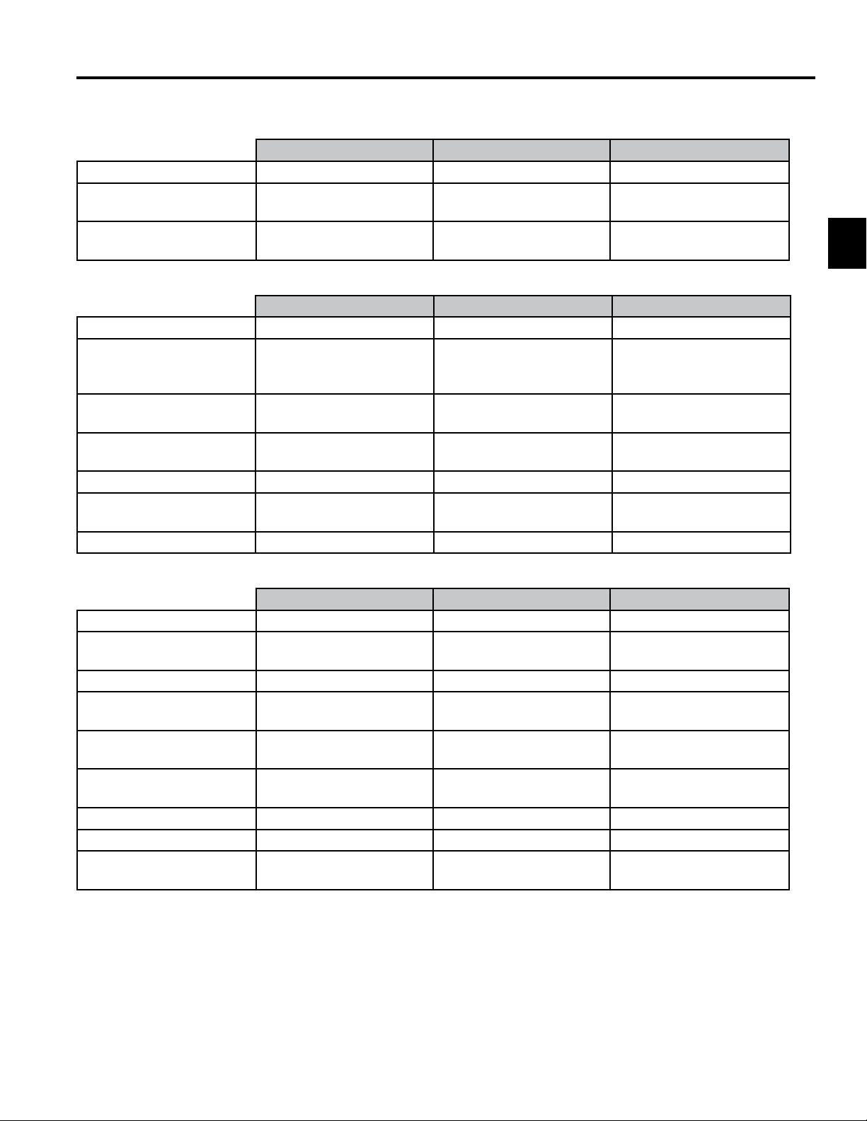
2009 - 2010 TITAN ZX Specications
Congurations TITAN ZX5000 TITAN ZX4800 TITAN ZX5450
22 HP Kawasaki V-Twin 50” SD, 3 Blades
23 HP Kohler Courage
‘Pro’ V-Twin
25 HP Kohler Courage
‘Pro’ V-Twin
Power Systems TITAN ZX5000 TITAN ZX4800 TITAN ZX5450
Clutch Electric Electric Electric
Transaxles Twin Hydro-Gear ZT2800
Hydrostatic Transaxle w/
charge pumps
Drive Belt Drive with self-
tensioning system
Maximum Ground Speed
(Fwd/Rev)
Rear Drive Tires 20” x 8.5”-8 4 ply rated 20” x 8.5”-8 4 ply rated 20” x 8.5”-8 4 ply rated
Front Caster Tires 410/350 x 5”
Fuel / Capacity 5 gallons (18.9 L) 5 gallons (18.9 L) 5 gallons (18.9 L)
7.5 mph/3.8 mph 7.5 mph/3.8 mph 7.5 mph/3.8 mph
Smooth Tread 4 ply rated
48” SD, 3 Blades
Twin Hydro-Gear ZT2800
Hydrostatic Transaxle w/
charge pumps
Belt Drive with self-
tensioning system
410/350 x 5”
Smooth Tread 4 ply rated
54” SD, 3 Blades
Twin Hydro-Gear ZT2800
Hydrostatic Transaxle w/
charge pumps
Belt Drive with self-
tensioning system
410/350 x 5”
Smooth Tread 4 ply rated
2
Mowing Deck: TITAN ZX5000 TITAN ZX4800 TITAN ZX5450
Type Side Discharge Side Discharge Side Discharge
Deck Construction/
Material
Spindle Housings Die cast aluminum Die cast aluminum Die cast aluminum
Spindle Shaft/Bearings Three 17mm permanently
Blades Three 17.5” x 2.25” x
Blade Tip Speed 18,889 ft/min @ 3650
Cutting Height 1.5” to 4.5” (13 Positions) 1.5” to 4.5” (13 Positions) 1.5” to 4.5” (13 Positions)
Anti-Scalp Rollers 3 adjustable 3 adjustable 3 adjustable
Frame Construction 1.5” x 3” (.109 wall)
12 gauge stamped steel 10 gauge fabricated steel 10 gauge fabricated steel
lubed ball bearings
.164” heat treated steel
RPM
Mechanical Steel Tubing
Three 25mm permanently
lubed ball bearings
Three 16.5” x 2.25” x
.164” heat treated steel
18,670 ft/min @ 3700
RPM
1.5” x 3” (.109 wall)
Mechanical Steel Tubing
Three 25mm permanently
lubed ball bearings
Three 18.75” x 2.25” x
.164” heat treated steel
18,644 ft/min @ 3700
RPM
1.5” x 3” (.109 wall)
Mechanical Steel Tubing
Toro TITAN 2009-2013 Service Manual
2-1
Page 12
2
SPECIFICATIONS
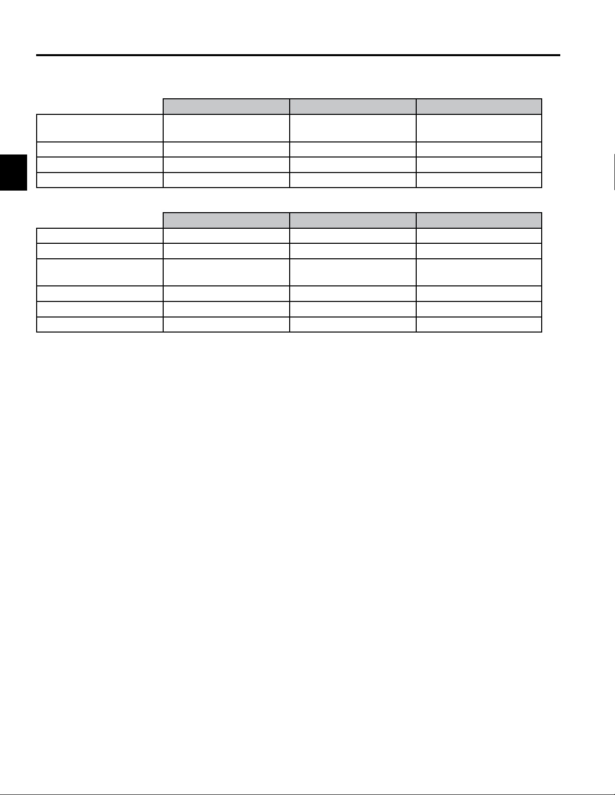
2009 - 2010 TITAN ZX Specications cont.
Operator Zone TITAN ZX5000 TITAN ZX4800 TITAN ZX5450
Steering Controls Dual Wrap-Around Levers
with cushion grips
Arm Rests Standard Standard Standard
Beverage Holder Standard Standard Standard
Hour Meter Standard Standard Standard
Dimensions TITAN ZX500 TITAN ZX4800 TITAN ZX5450
Weight 605 lbs. (estimated) 665 lbs. (estimated) 679 lbs. (estimated)
Width Outside Tires 45.3” (115.1cm) 45.3” (115.1cm) 46.3” (117.6cm)
Width Outside Deck 63.1” (160.3cm)
Deector down
Wheel Base 49.4” (125.5cm) 49.4” (125.5cm) 49.4” (125.5cm)
Overall Length 77.3” (196.3cm) 77.3” (196.3cm) 77.3” (196.3cm)
Height 43.4” (110.2cm) 43.4” (110.2cm) 43.4” (110.2cm)
Dual Wrap-Around Levers
with cushion grips
61.5” (156.2cm)
Deector down
Dual Wrap-Around Levers
with cushion grips
67.9” (172.5cm)
Deector down
2-2
Toro TITAN 2009-2013 Service Manual
Page 13
SPECIFICATIONS
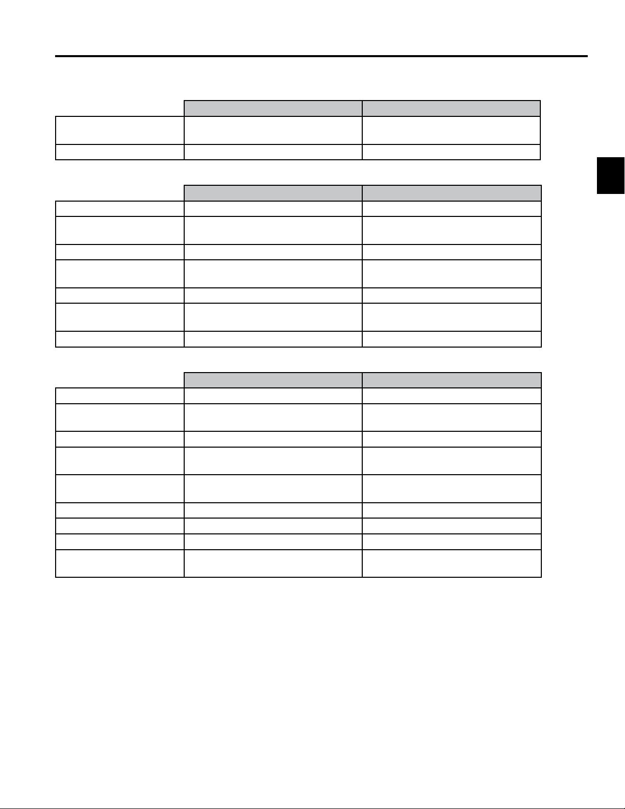
2009 - 2010 TITAN ZX Specications cont.
Congurations TITAN ZX6030 TITAN ZX6050
27 HP Kohler Courage
‘Pro’ V-Twin
26 HP Kawasaki V-Twin 60” SD, 3 Blades
Power Systems TITAN ZX6030 TITAN ZX6050
Clutch Electric Electric
Transaxles Twin Hydro-Gear ZT2800 Hydrostatic
Drive Belt Drive with self-tensioning system Belt Drive with self-tensioning system
Maximum Ground Speed
(Fwd/Rev)
Rear Drive Tires 20” x 10” – 8 4 ply rated 20” x 10” – 8 4 ply rated
Front Caster Tires 410/350 x 5”
Fuel/Capacity 5 gallons (18.9 L) 5 gallons (18.9 L)
60” SD, 3 Blades
Twin Hydro-Gear ZT2800 Hydrostatic
Transaxle w/charge pumps
7.5 mph/3.8mph 7.5 mph/3.8mph
Smooth tread 4 ply rated
Transaxle w/charge pumps
410/350 x 5”
Smooth tread 4 ply rated
2
Mowing Deck TITAN ZX6030 TITAN ZX6050
Type Side Discharge Side Discharge
Deck Construction/
Material
Spindle Housing Die cast aluminum Die cast aluminum
Spindle Shaft/Bearings Three 25mm dia. permanently lubed
Blades Three 20.5” x 2.25” x .164
Blade Tip Speed 18,908 ft/min @ 3700 RPM 18,908 ft/min @ 3700 RPM
Cutting Height 1.5” to 4.5” (13 Positions) 1.5” to 4.5” (13 Positions)
Anti-Scalp Rollers 3 adjustable 3 adjustable
Frame Construction 1.5” x 3” (.109 wall)
10 gauge fabricated steel 10 gauge fabricated steel
Three 25mm dia. permanently lubed
ball bearings
heat-treated steel blades
Mechanical steel tubing
ball bearings
Three 20.5” x 2.25” x .164
heat-treated steel blades
1.5” x 3” (.109 wall)
Mechanical steel tubing
Toro TITAN 2009-2013 Service Manual
2-3
Page 14
2
SPECIFICATIONS
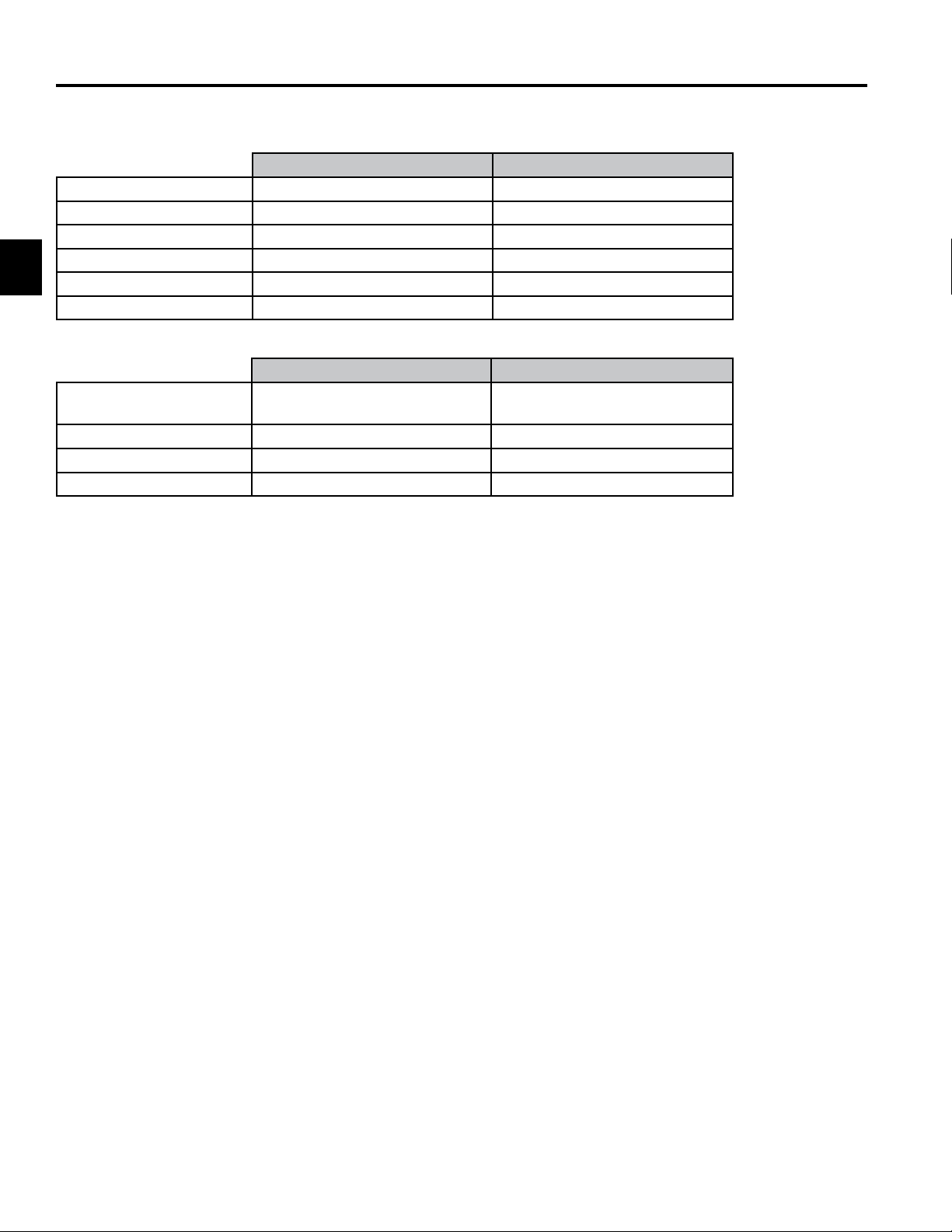
2009 - 2010 TITAN ZX Specications cont.
Dimensions TITAN ZX6030 TITAN ZX6050
Weight 724 lbs (estimated) 724 lbs. (estimated)
Width Outside Deck 75.1” (190.8cm) Deector Down 75.1” (190.8cm) Deector Down
Width Outside Tires 46.3” (117.6cm) 46.3” (117.6cm)
Wheel Base 49.4” (125.5cm) 49.4” (125.5cm)
Overall Length 78.6” (199.6cm) 78.6 (199.6cm)
Height 43.4” (110.2cm) 43.4” (110.2cm)
Operator Zone TITAN ZX6030 TITAN ZX6050
Steering Controls Dual Wrap-Around levers with
cushion grips
Arm Rests Standard Standard
Beverage Holder Standard Standard
Hour Meter Standard Standard
Dual Wrap-Around levers with
cushion grips
2-4
Toro TITAN 2009-2013 Service Manual
Page 15
SPECIFICATIONS
2011 - 2013 TITAN ZX & MX Specications
Congurations TITAN ZX4820 TITAN ZX5420 TITAN ZX6020
21.5 HP Kawasaki V-Twin 48” SD, 3 Blades
23 HP Kawasaki V-Twin 54” SD, 3 Blades
24 HP Kawasaki V-Twin 60” SD, 3 Blades
Power Systems TITAN ZX4820 TITAN ZX5420 TITAN ZX6020
Clutch Electric Electric Electric
Transaxles Twin Hydro-Gear ZT-2800
w/charge pumps
Drive Belt Drive with self-
tensioning system
Maximum Ground Speed 7.5 mph/3.8 mph 7.5 mph/3.8 mph 7.5 mph/3.5 mph
Rear Drive Tires 20” x 8”-8 4-ply rated 20” x 10”-8 4-ply rated 20” x 10”-8 4-ply rated
Front Caster Tires 410/350x5 smooth
4-ply rated
Fuel/Capacity 5 gallons (18.9 L) 5 gallons (18.9 L) 5 gallons (18.9 L)
Twin Hydro-Gear ZT-2800
w/charge pumps
Belt Drive with selftensioning system
410/350x5 smooth
4-ply rated
Twin Hydro-Gear ZT-2800
w/charge pumps
Belt Drive with selftensioning system
410/350x5 smooth
4-ply rated
2
Mowing Deck TITAN ZX4820 TITAN ZX5420 TITAN ZX6020
Type Side Discharge Side Discharge Side Discharge
Deck Construction 10 gauge fabricated steel 10 gauge fabricated steel 10 gauge fabricated steel
Spindle Housings Die cast aluminum Die cast aluminum Die cast aluminum
Spindle Shaft/Bearings Three 25mm diameter
spindles in permanently
lubed ball bearings
Blade Tip Speed 18,800 ft/min @
3700 RPM
Cutting Height 1.5” to 4.5” 13 positions 1.5” to 4.5” 13 positions 1.5” to 4.5” 13 positions
Anti-Scalp Rollers 3 Adjustable 3 Adjustable 3 Adjustable
Frame Construction 1.5” X 3” (.109” wall)
Mechanical Steel Tubing
Dimensions TITAN ZX4820 TITAN ZX5420 TITAN ZX6020
Weight 735 lbs. (estimated) 750 lbs. (estimated) 773 lbs. (estimated)
Width Outside Tires 44.3” (117.6cm) 46.4” (117.9cm) 46.4” (117.9cm)
Overall Width 61.5” Deector Down
52.4” Deector Up
Wheel Base 49.4” (125.5cm) 49.4” (125.5cm) 49.4” (125.5cm)
Overall Length 77.3” (196.3cm) 77.3” (196.3cm) 77.3” (196.3cm)
Height 72.4” ROPS Up
45.6” ROPS Down
Three 25mm diameter
spindles in permanently
lubed ball bearings
18,644 ft/min @
3700 RPM
1.5” X 3” (.109” wall)
Mechanical Steel Tubing
67.9” Deector Down
57.7” Deector Up
72.4” ROPS Up
45.6” ROPS Down
Three 25mm diameter
spindles in permanently
lubed ball bearings
18,908 ft/min @
3700 RPM
1.5” X 3” (.109” wall)
Mechanical Steel Tubing
75.0” Deector Down
63.0” Deector Up
72.4” ROPS Up
45.6” ROPS Down
Toro TITAN 2009-2013 Service Manual
2-5
Page 16

2
SPECIFICATIONS
2011 - 2013 TITAN ZX & MX Specications cont.
Congurations TITAN MX4880 TITAN MX5480 TITAN MX6080
21.5 HP Kawasaki V-Twin 48” SD, 3-Blades
23 HP Kawasaki V-Twin 54” SD, 3-Blades
24 HP Kawasaki V-Twin 60” SD, 3-Blades
Power Systems TITAN MX4880 TITAN MX5480 TITAN MX6080
Clutch Electric Electric Electric
Transaxles Twin Hydro-Gear ZT-3100
with Charge Pump,
Shock Valves and
Heavy Duty Gears
Drive Belt Drive self-tensioning
system
Maximum Ground Speed 7.5 mph/3.8 mph 7.5 mph/3.8 mph 7.5 mph/3.8 mph
Rear Drive Tires 22”X10”-10 4 ply rated 22”X10”-10 4 ply rated 22”X10”-10 4 ply rated
Front Caster Tires 12”X6”-6 Smooth Tread 12”X6”-6 Smooth Tread 12”X6”-6 Smooth Tread
Fuel / Capacity 5 gallons (18.9 L) 5 gallons (18.9L) 5 gallons (18.9L)
Twin Hydro-Gear ZT-3100
with Charge Pump,
Shock Valves and
Heavy Duty Gears
Belt Drive self-tensioning
system
Twin Hydro-Gear ZT-3100
with Charge Pump,
Shock Valves and
Heavy Duty Gears
Belt Drive self-tensioning
system
Mower Decks TITAN MX4880 TITAN MX5480 TITAN MX6080
Type Side Discharge Side Discharge Side Discharge
Deck Construction
Material
Spindle Housing Die cast aluminum Die cast aluminum Die cast aluminum
Spindle Shaft/Bearings Three 25mm diameter
Blade Tip Speed 18,800 ft/min @
Cutting Height 1.5” to 4.5” 13 Positions 1.5” to 4.5” 13 Positions 1.5” to 4.5” 13 Positions
Anti-Scalp Rollers 3 Adjustable 3 Adjustable 3 Adjustable
Frame Construction 1.5” X 3” (.109” wall)
Dimensions TITAN MX4880 TITAN MX5480 TITAN MX6080
Weight 797 lbs. (estimated) 813 lbs. (estimated)
Width Outside Tires 47.2” (119.9cm) 47.2” (119.9cm) 47.2” (119.9cm)
Width Outside Deck 61.5” Deector Down
Wheel Base 49.2” (125.0cm) 49.2” (125.0cm) 49.2” (125.0cm)
Overall Length 77.4” (196.6cm) 77.4” (196.6cm) 77.4” (196.6cm)
Overall Height 73.4” ROPS Up
10 gauge fabricated steel 10 gauge fabricated steel 10 gauge fabricated steel
spindles in permanently
lubed ball bearings
3700 RPM
Mechanical Steel Tubing
52.4” Deector Up
46.9” ROPS Down
Three 25mm diameter
spindles in permanently
lubed ball bearings
18,644 ft/min @
3700 RPM
1.5” X 3” (.109” wall)
Mechanical Steel Tubing
67.9” Deector Down
57.7” Deector Up
73.4” ROPS Up
46.9” ROPS Down
Three 25mm diameter
spindles in permanently
lubed ball bearings
18,908 ft/min @
3700 RPM
1.5” X 3” (.109” wall)
Mechanical Steel Tubing
75.0” Deector Down
63.0” Deector Up
73.4” ROPS Up
46.9” ROPS Down
2-6
Toro TITAN 2009-2013 Service Manual
Page 17
2011 - 2013 TITAN ZX & MX Specications cont.
Congurations TITAN ZX5020
22 HP Kawasaki V-Twin
23 HP Kohler Courage ‘Pro’ VTwin
24 HP Kawasaki V-Twin
Power Systems TITAN ZX5020
Clutch Electric
Transaxles Twin Hydro-Gear ZT2800
Drive Belt Drive with self-
Maximum Ground Speed (Fwd/
Rev)
Rear Drive Tires 20” x 10” 4 ply rated
Front Caster Tires 11 x 4
Fuel / Capacity 5 gallons (18.9 L)
50” SD, 3 Blades
Hydrostatic Transaxle w/
charge pumps
tensioning system
7.5 mph/3.8 mph
SPECIFICATIONS
2
Mowing Deck TITAN ZX5020
Type Side Discharge
Deck Construction/ Material 12 gauge stamped steel
Spindle Housings Die cast aluminum
Spindle Shaft/Bearings Three 17mm permanently
lubed ball bearings
Blades Three 17.5” x 2.25” x .164”
heat treated steel
Blade Tip Speed 18,889 ft/min @ 3650 RPM
Cutting Height 1.5” to 4.5” (13 Positions)
Anti-Scalp Rollers 3 adjustable
Frame Construction 1.5” x 3” (.109 wall)
Mechanical Steel Tubing
Toro TITAN 2009-2013 Service Manual
2-7
Page 18
2
SPECIFICATIONS
2011 - 2013 TITAN ZX & MX Specications cont.
Operator Zone TITAN ZX5020
Steering Controls Dual Wrap-Around Levers
with cushion grips
Arm Rests Standard
Beverage Holder Standard
Hour Meter Standard
Dimensions TITAN ZX5020
Weight 605 lbs. (estimated)
Width Outside Tires 45.3” (115.1cm)
Width Outside Deck 63.1” (160.3cm)
Deector down
Wheel Base 49.4” (125.5cm)
Overall Length 77.3” (196.3cm)
Height 43.4” (110.2cm)
2-8
Toro TITAN 2009-2013 Service Manual
Page 19

SPECIFICATIONS
Engine Specications
Model # Model Engine Information
74820 ZX5000 Briggs & Stratton, 22hp, High Idle: 3550 ± 100 RPM
74822 ZX5400 Kohler, 23hp, High Idle: 3600 ± 75 RPM
74823 ZX6000 Kohler, 25hp, High Idle: 3600 ± 75 RPM
74824 ZX6050 Kawasaki, 26hp, High Idle: 3600 ± 75 RPM
74830 ZX4800 Kohler, 23hp, High Idle: 3600 ± 75 RPM
74832 ZX5450 Kohler, 25hp, High Idle: 3600 ± 75 RPM
74833 ZX6030 Kohler, 27hp, High Idle: 3600 ± 75 RPM
74840 ZX5020 Kohler, 23hp, High Idle: 3600 ± 75 RPM
74841 ZX4820 Kawasaki, 21.5hp, High Idle: 3600 ± 100 RPM
74842 ZX5420 Kawasaki, 23hp, High Idle: 3600 ± 100 RPM
74843 ZX6020 Kawasaki, 24hp, High Idle: 3600 ± 100 RPM
74845 ZX4820 Kawasaki, 21.5hp, High Idle: 3600 ± 100 RPM
74929 ZX6020 Kawasaki, 24hp, High Idle: 3600 ± 100 RPM
74871 MX4880 Kawasaki, 21.5hp, High Idle: 3600 ± 100 RPM
74872 MX5480 Kawasaki, 23hp, High Idle: 3600 ± 100 RPM
74873 MX6080 Kawasaki, 24hp, High Idle: 3600 ± 100 RPM
2
74912 ZX4800 (INTL) Kohler, 23hp, High Idle: 3000 ± 75 RPM
74914 ZX5400 (INTL) Kawasaki, 24hp, High Idle: 3000 ± 100 RPM
74920 ZX4820 (INTL) Kawasaki, 24hp, High Idle: 3000 ± 100 RPM
74924 ZX5420 (INTL) Kawasaki, 24hp, High Idle: 3000 ± 100 RPM
Toro TITAN 2009-2013 Service Manual
2-9
Page 20
2
SPECIFICATIONS
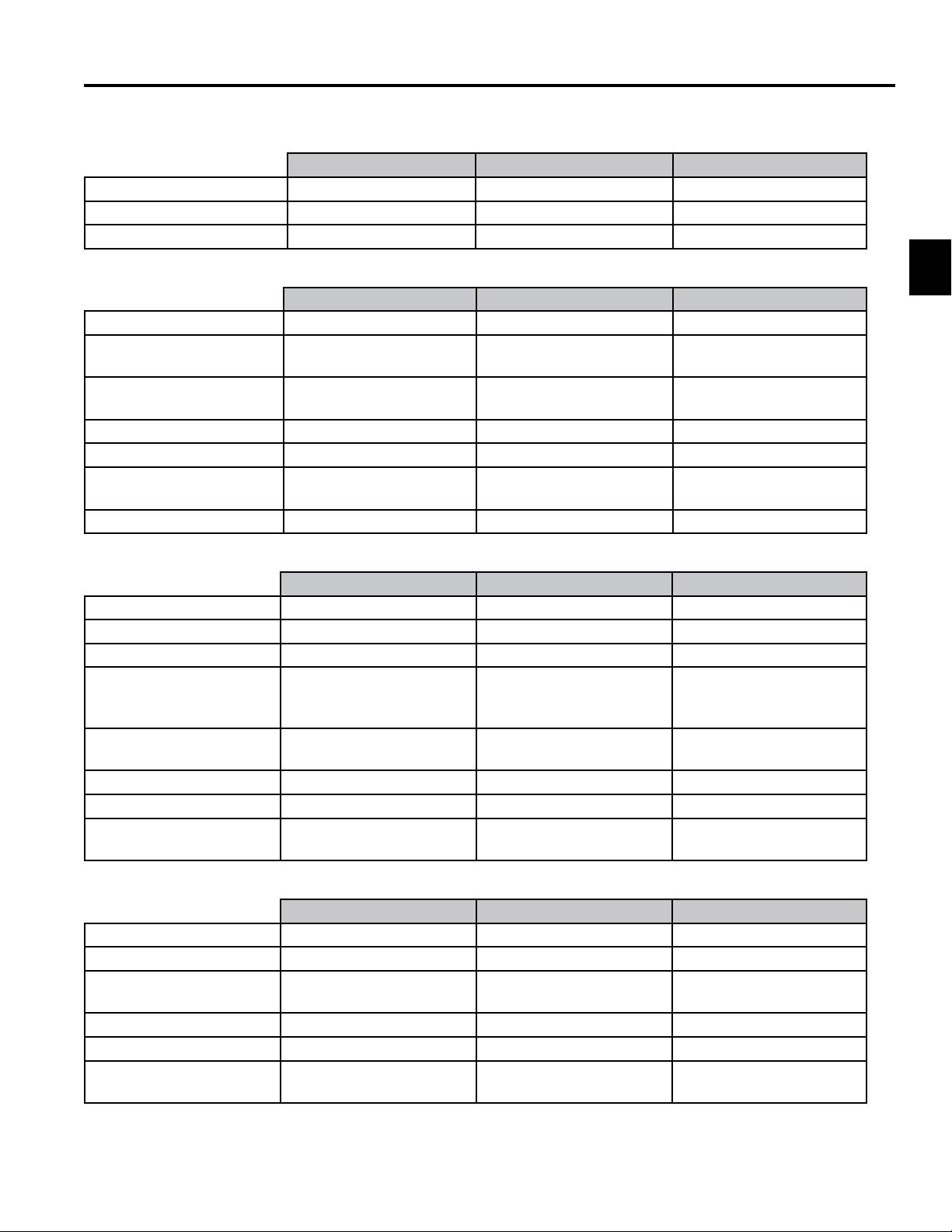
Hydro-Gear ZT-2800 & ZT-3100 Hydrostatic Transaxles
Fig. 001 PICT-1002
Lubrication Toro HYPR-OIL 500® or 20w50 Engine Oil
Oil Capacity ZT-2800 77.23 . oz. (2284ml) each
Oil Level Check Check expansion reservoir and if necessary add the specied oil to the FULL COLD
line. See illustration below. Also see the Hydro-Gear ZT-2800 / ZT-3100 service manual
(BLN-52441).
Fluid Change Interval After the First 50 hours - change the oil and lters for the hydraulic system and bleed
the system.
Every 400 Hours - change the oil and lters for the hydraulic system and bleed the
system.
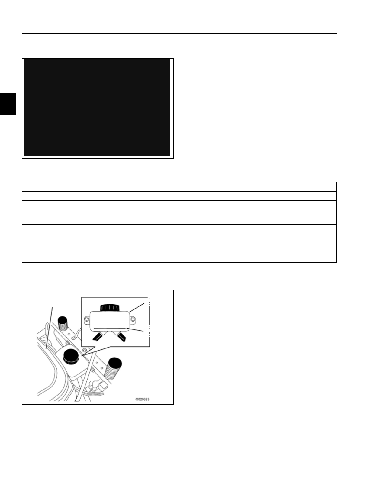
Checking the Hydraulic Oil Level
C
A
B
Fig. 002 g. 51 G020323
A. Expansion reservoir C. Engine
B. Full cold line
2-10
Toro TITAN 2009-2013 Service Manual
Page 21
SPECIFICATIONS
Torque Specications
Recommended fastener torque values are listed in the
following tables. For critical applications, as determined
by Toro, either the recommended torque or a torque
that is unique to the application is clearly identied and
specied in the service manual.
These torque specications for the installation and
tightening of fasteners shall apply to all fasteners
which do not have a specic requirement identied
in the service manual. The following factors shall be
consid ered when applying torque: cleanliness of the
fastener, use of a thread sealant (e.g. Loctite®), degree
of lubrication on the fastener, presence of a prevailing
torque feature, hardness of the surface underneath of
the fastener’s head, or similar condition which affects the
installation.
As noted in the following tables, torque values should
be reduced by 25% for lubricated fasteners to achieve
the similar stress as a dry fastener. Torque values may
also have to be reduced when the fastener is threaded
into aluminum or brass. The specic torque value should
be determined based on the aluminum or brass material
strength, fastener size, length of thread engagement,
etc.
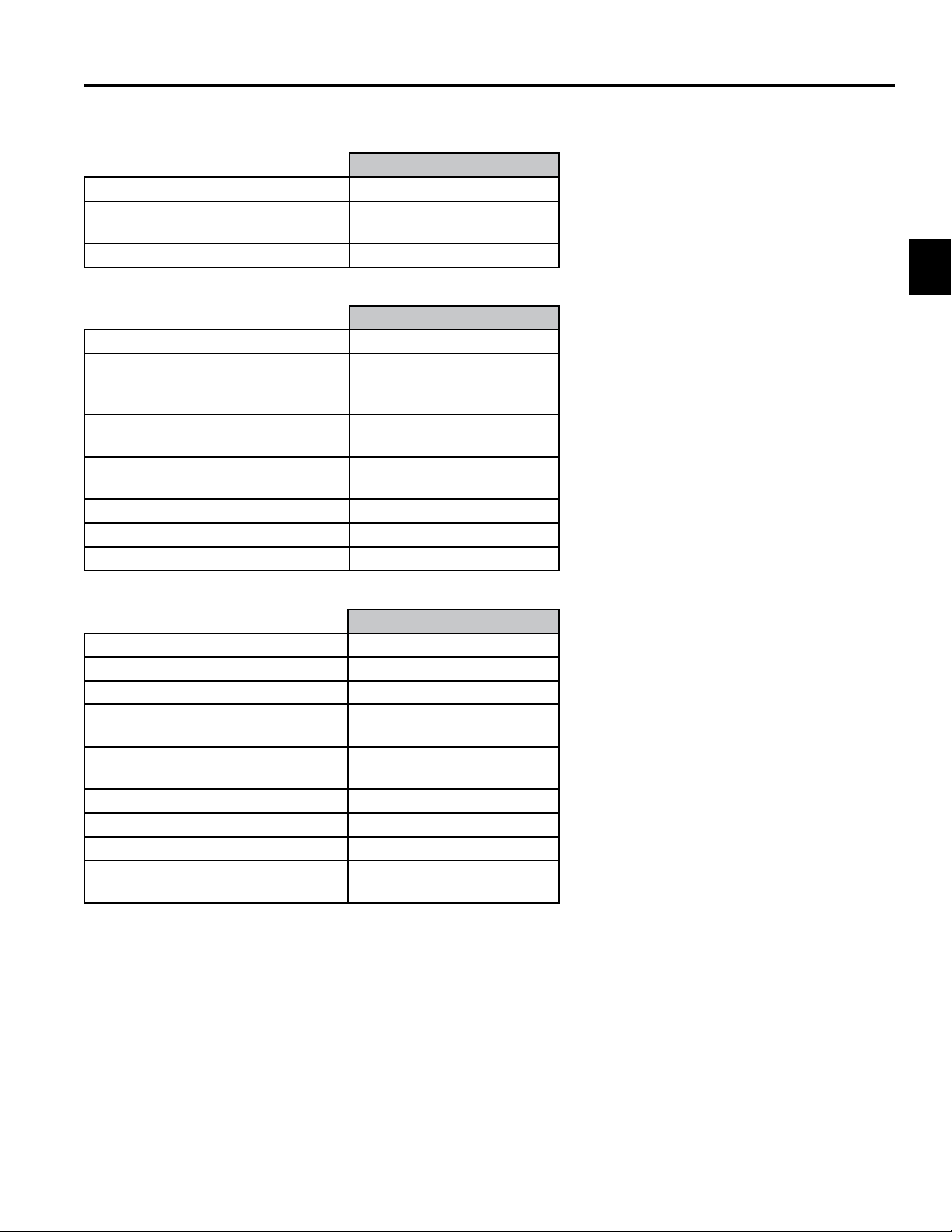
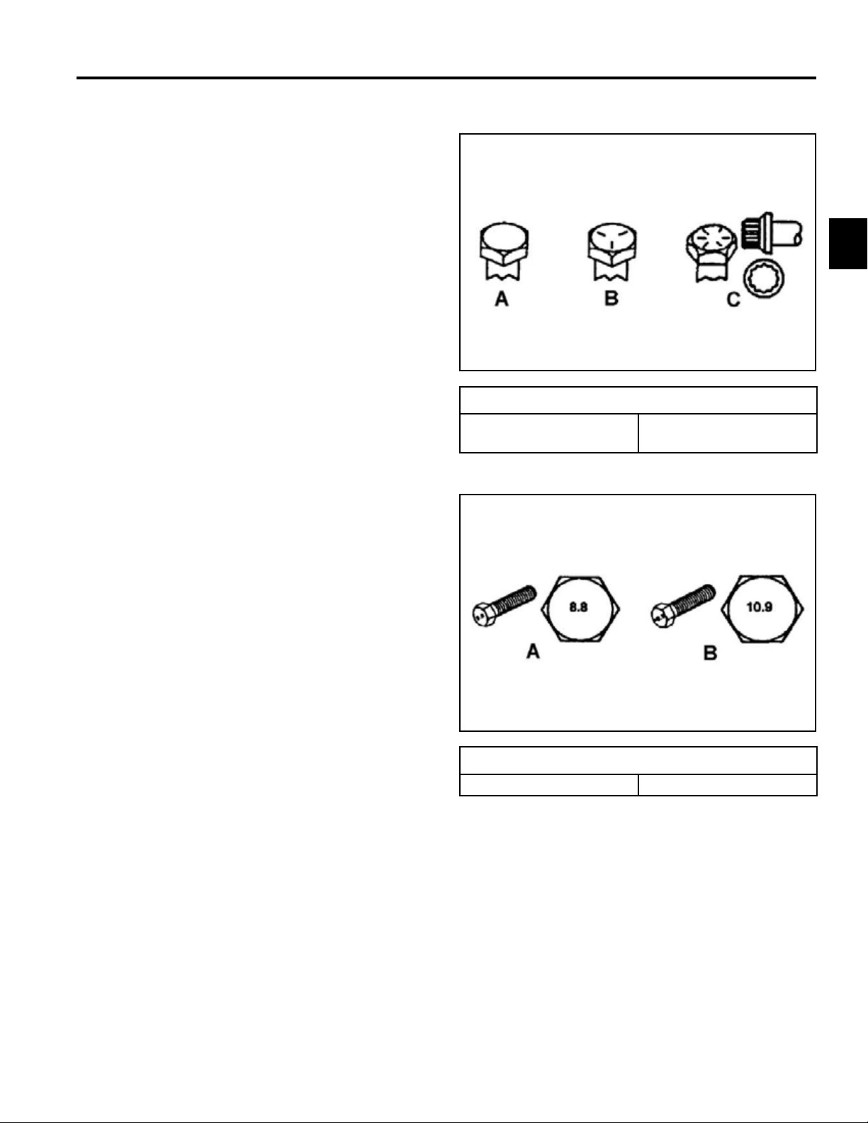
Fastener Identication
Inch Series bolts and Screws
(A) Grade 1 & 2
(B) Grade 5
2
(C) Grade 8
The standard method of verifying torque shall be performed by marking a line on the fastener (head or nut)
and mating part, then back off fastener 1/4 of a turn.
Measure the torque required to tighten the fastener until
the lines match up.
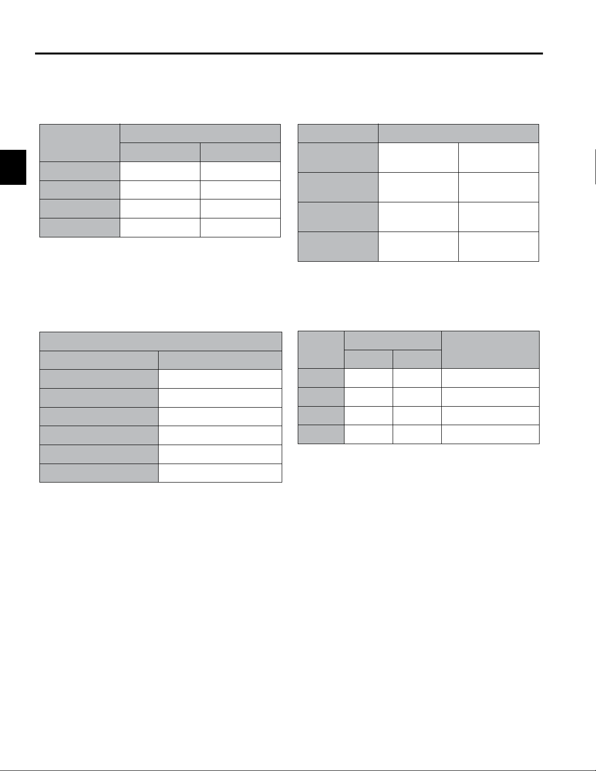
Metric Bolts and Screws
(A) Class 8.8 (B) Class 10.9
Toro TITAN 2009-2013 Service Manual
2-11
Page 22

SPECIFICATIONS
Standard Torque for Dry, Zinc Plated, and Steel Fasteners (Inch Series)
Standard Torque for Dry, Zinc Plated & Steel Fasteners (Inch Series)
Grade 1, 5, &
Thread Size
2
# 6 - 32 UNC
# 6 - 40 UNF 17 ± 2 190 ± 20 25 ± 2 280 ± 20
# 8 - 32 UNC
# 8 - 36 UNF 31 ± 3 350 ± 30 43 ± 4 31 ± 3
# 10 - 24 UNC
#10 - 32 UNF 48 ± 4 540 ± 45 68 ± 6 765 ± 70
1/4 - 20 UNC 48 ± 7 53 ± 7 599 ± 79 100 ± 10 1125 ± 100 140 ± 15 1580 ± 170
1/4 - 28 UNF 53 ± 7 65 ± 10 734 ± 113 115 ± 10 1300 ± 100 160 ± 15 1800 ± 170
5/16 - 18 UNC 115 ± 15 105 ± 15 1186 ± 169 200 ± 25 2250 ± 280 300 ± 30 3390 ± 340
5/16 - 24 UNF 138 ± 17 128 ± 17 1446 ± 192 225 ± 25 2540 ± 280 325 ± 30 3670 ± 340
3/8 - 16 UNC 16 ± 2 16 ± 2 22 ± 3 30 ± 3 41 ± 4 43 ± 4 58 ± 5
3/8 - 24 UNF 17 ± 2 18 ± 2 24 ± 3 35 ± 3 47 ± 4 50 ± 4 68 ± 5
7/16 - 14 UNC 27 ± 3 27 ± 3 37 ± 4 50 ± 5 68 ± 7 70 ± 7 68 ± 9
7/16 - 20 UNF 29 ± 3 29 ± 3 39 ± 4 55 ± 5 75 ± 7 77 ± 7 104 ± 9
1/2 - 13 UNC 30 ± 3 48 ± 7 65 ± 9 75 ± 8 102 ± 11 105 ± 10 142 ± 14
1/2 - 20 UNF 32 ± 3 53 ± 7 72 ± 9 85 ± 8 115 ± 11 120 ± 10 163 ± 14
5/8 - 11 UNC 65 ± 10 88 ± 12 119 ± 16 150 ± 15 203 ± 20 210 ± 20 285 ± 27
5/8 - 18 UNF 75 ± 10 95 ± 15 129 ± 20 170 ± 15 230 ± 20 240 ± 20 325 ± 27
3/4 - 10 UNC 93 ± 12 140 ± 20 190 ± 27 265 ± 25 359 ± 34 374 ± 35 508 ± 47
3/4 - 16 UNF 115 ± 15 165 ± 25 224 ± 34 300 ± 25 407 ± 34 420 ± 35 569 ± 47
7/8 - 9 UNC 140 ± 20 225 ± 25 305 ± 34 430 ± 45 583 ± 61 600 ± 60 813 ± 81
7/8 - 14 UNF 155 ± 25 260 ± 30 353 ± 41 475 ± 45 644 ± 61 660 ± 60 895 ± 81
8 with Thin
Height Nuts
In-lb In-lb N-cm In-lb N-cm In-lb N-cm
10 ± 2 13 ± 2 147 ± 23
13 ± 2 25 ± 5 282 ± 30
18 ± 2 30 ± 5 339 ± 56
ft-lb ft-lb N-m ft-lb N-m ft-lb N-m
SAE Grade 1 Bolts, Screws,
Studs, & Sems with Regular
Height Nuts (SAE J995
Grade 2 or Stronger Nuts)
SAE Grade 5 Bolts, Screws,
Studs, & Sems with Regular
Height Nuts (SAE J995
Grade 2 or Stronger Nuts)
15 ± 2 169 ± 23 23 ± 2 260 ± 34
29 ± 3 330 ± 30 41 ± 4 460 ± 45
42 ± 4 475 ± 45 60 ± 6 674 ± 70
SAE Grade 8 Bolts, Screws,
Studs, & Sems with Regular
Height Nuts (SAE J995
Grade 2 or Stronger Nuts)
Note: Reduce torque values listed in the table above
by 25% for lubricated fasteners. Lubricated fasteners
are defined as threads coated with a lubricant such as
oil, graphite, or thread sealant such as Loctite.
Note: Torque values may have to be reduced when
installing fasteners into threaded aluminum or brass.
The specific torque value should be determined based
on the fastener size, the aluminum or base material
strength, length of thread engagement, etc.
2-12
Toro TITAN 2009-2013 Service Manual
Note: The nominal torque values listed above for
Grade 5 and 8 fasteners are based on 75% of the
minimum proof load specified in SAE J429. The
tolerance is approximately ± 10% of the nominal torque
value. Thin height nuts include jam nuts.
Page 23

SPECIFICATIONS
Standard Torque for Dry, Zinc, and Steel Fasteners (Metric Fasteners)
Standard Torque for Dry, Zinc & Steel Fasteners (Metric Fasteners)
Class 8.8 Bolts, Screws, and Studs with
Thread Size
M5 X 0.8 57 ± 5 in-lb 644 ± 68 N-cm 78 ± 8 in-lb 881 ± 90 N-cm
M6 X 1.0 96 ± 10 in-lb 1085 ± 113 N-cm 133 ± 14 in-lb 1503 ± 158 N-cm
M8 X 1.25 19 ± 2 ft-lb 26 ± 3 N-m 28 ± 3 ft-lb 38 ± 4 N-m
M10 X 1.5 38 ± 4 ft-lb 52 ± 5 N-m 54 ± 6 ft-lb 73 ± 8 N-m
M12 X 1.75 66 ± 7 ft-lb 90 ± 10 N-m 93 ± 10 ft-lb 126 ± 14 N-m
M16 X 2.0 166 ± 15 ft-lb 225 ± 23 N-m 229 ± 23 ft-lb 310 ± 31 N-m
M20 X 2.5 325 ± 33 ft-lb 440 ± 45 N-m 450 ± 36 ft-lb 610 ± 62 N-m
Note: Reduce torque values listed in the table above
by 25% for lubricated fasteners. Lubricated fasteners
are defined as threads coated with a lubricant such as
oil, graphite, or thread sealant such as Loctite.
Note: Torque values may have to be reduced when
installing fasteners into threaded aluminum or brass.
The specific torque value should be determined based
on the fastener size, the aluminum or base material
strength, length of thread engagement, etc.
Regular Height Nuts
(Class 8 or Strong Nuts)
Note: The nominal torque values listed above are
based on 75% of the minimum proof load specified in
SAE J1199. The tolerance is approximately ± 10% of
the nominal torque value. Thin height nuts include jam
nuts.
Class 10.9 Bolts, Screws, and Studs with
Regular Height Nuts (
Class 10 or Strong Nuts)
2
Toro TITAN 2009-2013 Service Manual
2-13
Page 24
SPECIFICATIONS
Other Torque Specifications
Other Torque Specications
SAE Grade 8 Steel Set Screws
Recommended Torque
Square Head Hex Socket
2
Thread Size
1/4 - 20 UNC 140 ± 20 in-lb 73 ± 12 in-lb
5/16 - 18 UNC 215 ± 35 in-lb 145 ± 20 in-lb
3/8 - 16 UNC 35 ± 10 ft-lb 18 ± 3 ft-lb
1/2 - 13 UNC 75 ± 15 ft-lb 50 ± 10 ft-lb
Thread Cutting Screws
(Zinc Plated Steel)
Type 1, Type 23, or Type F
Thread Size Baseline Torque*
No. 6 - 32 UNC 20 ± 5 in-lb
Wheel Bolts and Lug Nuts
Thread Size Recommended Torque**
7/16 - 20 UNF
Grade 5
1/2 - 20 UNF
Grade 5
M12 X 1.25
Class 8.8
M12 X 1.5
Class 8.8
65 ± 10 ft-lb 88 ± 14 N-m
80 ± 10 ft-lb 108 ± 14 N-m
80 ± 10 ft-lb 108 ± 14 N-m
80 ± 10 ft-lb 108 ± 14 N-m
** For steel wheels and non-lubricated fasteners.
Thread Cutting Screws
(Zinc Plated Steel)
Thread
Size
No. 6 18 20 20 ± 5 in-lb
Threads per Inch
Baseline Torque*
Type A Type B
No. 8 - 32 UNC 30 ± 5 in-lb
No.10 - 24 UNC 38 ± 7 in-lb
1/4 - 20 UNC 85 ± 15 in-lb
5/16 - 18 UNC 110 ± 20 in-lb
3/8 - 16 UNC 200 ± 100 in-lb
Conversion Factors
in-lb X 11.2985 = N-cm
ft-lb X 1.3558 = N-m
No. 8 15 18 30 ± 5 in-lb
No. 10 12 16 38 ± 7 in-lb
No. 12 11 14 85 ± 15 in-lb
* Hole size, material strength, material thickness and
finish must be considered when determining specific
torque values. All torque values are based on nonlubricated fasteners.
N-cm X - 0.08851 = in-lb
N-cm X 0.73776 = ft-lb
2-14
Toro TITAN 2009-2013 Service Manual
Page 25

Equivalents & Conversions
Equivalents and Conversions
Decimal and Millimeter Equivalents
Decimal & Millimeter Equivalents
Fractions Decimals mm Fractions Decimals mm
1/64 0.015625 0.397 33/64 0.515625 13.097
1/32 0.03125 0.794 16/32 0.53125 13.484
3/64 0.046875 1.191 35/64 0.546875 13.891
1/16 0.0625 1.588 9/16 0.5625 14.288
5/64 0.078125 1.984 37/64 0.578125 14.684
3/32 0.9375 2.381 19/32 0.59375 15.081
1/8 0.1250 3.175 5/8 0.6250 15.875
9/64 0.140625 3.572 41/64 0.640625 16.272
3/16 0.1875 4.762 11/16 0.6875 17.462
1/4 0.2500 6.350 3/4 0.7500 19.050
5/16 0.3125 7.541 13/16 0.8125 20.638
3/8 0.3750 9.525 7/8 0.8750 22.225
7/16 0.4375 11.112 15/16 0.9375 23.812
1/2 0.5000 12.700 1 1.000 25.400
5/32 0.15625 3.969 21/32 0.65625 16.669
11/64 0.171875 4.366 43/64 0.671875 17.066
13/64 0.203125 5.159 45/64 0.703125 17.859
7/32 0.21875 5.556 23/32 0.71875 18.256
15/64 0.234375 5.953 47/64 0.734375 18.653
17/64 0.265625 6.747 49/64 0.765625 19.447
9/32 0.28125 7.144 25/32 0.78125 19.844
19/64 0.296875 7.541 51/64 0.796875 20.241
21/64 0.328125 8.334 53/64 0.828125 21.034
11/32 0.34375 8.731 27/32 0.84375 21.431
23/64 0.359375 9.128 55/64 0.859375 21.828
25/64 0.390625 9.922 57/64 0.890625 22.622
13/32 0.40625 10.319 29/32 0.90625 23.019
27/64 0.421875 10.716 59/64 0.921875 23.416
29/64 0.453125 11.509 61/64 0.953125 24.209
15/32 0.46875 11.906 31/32 0.96875 24.606
31/64 0.484375 12.303 63/64 0.984375 25.003
1 mm = 0.03937 in. 0.001 in. = 0.0254 mm
SPECIFICATIONS
2
Toro TITAN 2009-2013 Service Manual
2-15
Page 26

2
U.S. to Metric Conversions
SPECIFICATIONS
U.S. to Metric Conversions
To Convert Into Multiply By
Miles
Yards
Linear
Measurement
Area
Volume
Weight
Pressure
Work
Liquid Volume
Liquid Flows
Temperature
Feet
Feet
Inches
Inches
Inches
Square Miles
Square Feet
Square Inches
Acre
Cubic Yards
Cubic Feet
Cubic Inches
Tons (Short)
Pounds
Ounces
Pounds/Sq. In. Kilopascal
Foot-pounds
Foot-pounds
Inch-pounds
Quarts
Gallons
Gallons/Minute Liters/Minute
Fahrenheit Celsius
Kilometers
Meters
Meters
Centimeters
Meters
Centimeters
Millimeters
Square Kilometers
Square Meters
Square Centimeters
Hectare
Cubic Meters
Cubic Meters
Cubic Centimeters
Metric Tons
Kilograms
Grams
Newton-Meters
Kilogram-Meters
Kilogram-Centimeters
Liters
Liters
1.609
0.9144
0.3048
30.48
0.0254
2.54
25.4
2.59
0.0929
6.452
0.4047
0.7646
0.02832
16.39
0.9078
0.4536
28.3495
6.895
1.356
0.1383
1.152144
0.9463
3.785
3.785
1. Subtract 32°
2. Multiply by 5/9
2-16
Toro TITAN 2009-2013 Service Manual
Page 27
CHASSIS
Model and Serial Number
Identication
The model and serial number identication plate is
located on the frame, near the engine, on the RH side of
the unit (Fig. 003).
Fig. 003 PICT-2057
Grease & Lubrication Point
Grease Type – No. 2 general-purpose lithium base
grease
A grease tting is located on each of the front wheel
hubs.
The front wheel hubs should be greased every 25 hrs.
(Fig. 004)
3
Fig. 004 PICT-1035
Toro TITAN 2009-2013 Service Manual
3-1
Page 28

CHASSIS
3
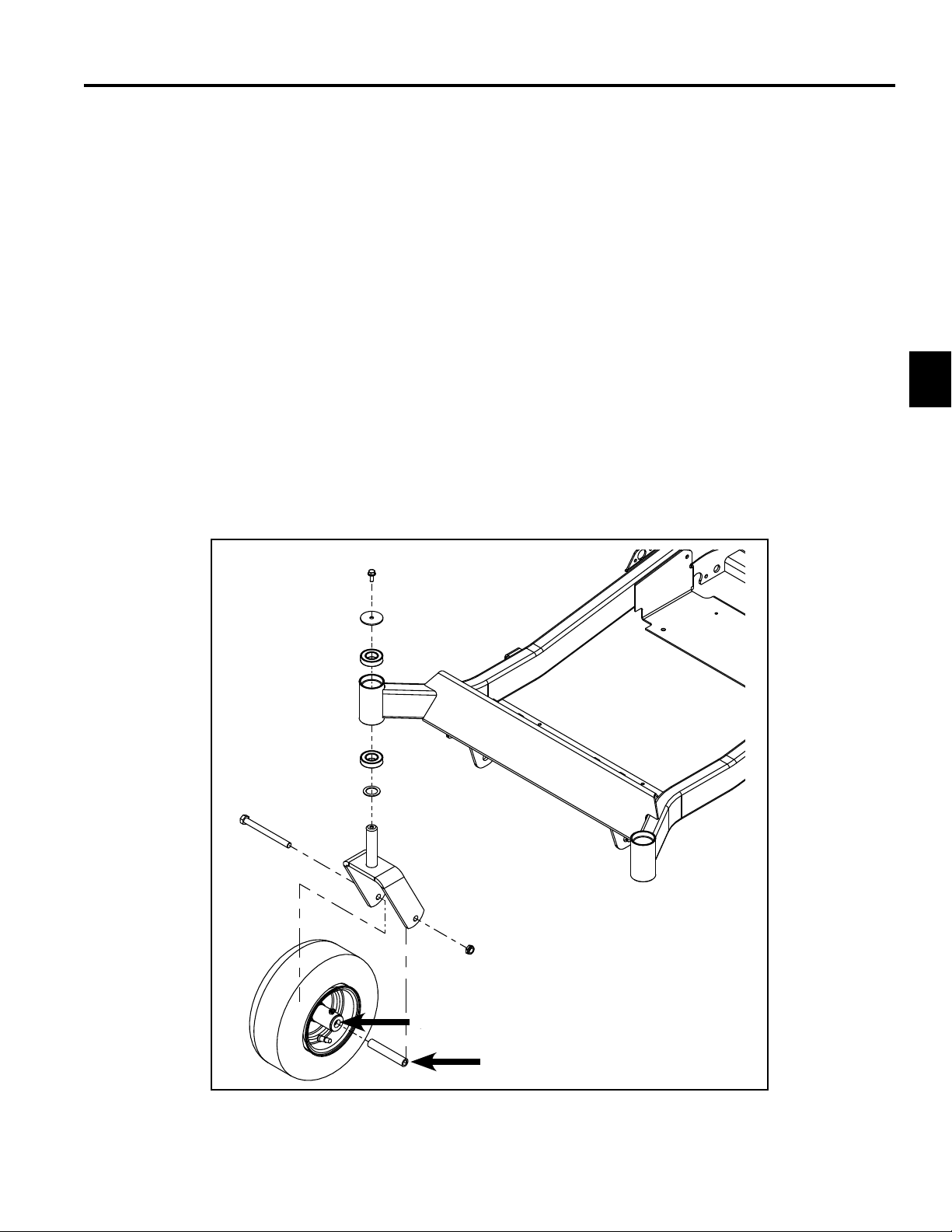
Front Axle / Caster Fork / Bearing Service
Front Axle / Caster Fork / Bearing Disassembly
1. Safely raise and support unit so front wheels are off
the ground.
2. Support under caster wheel and remove the fastener
(A).
3. Remove caster fork (B) from frame hub (C). Inspect
the caster fork shaft and thrust washer (D) for
excessive wear, replace if necessary.
4. Using an appropriate punch, tap out and remove the
LOWER bearings from the front axle (C).
5. Using an appropriate punch, tap out and remove the
UPPER bearings from the frame hub (C).
6. Properly clean and inspect the frame hub bearing
area.
Front Axle / Caster Fork / Bearing Assembly
1. Using a proper bearing installation tool, install new
upper and lower bearings into the frame hub making
sure they are fully seated.
2. Install thrust washer (D) onto the caster fork shaft.
3. Install the caster assembly up through the bearings
and hold in position.
4. Install washer (E).
5. Install fastener (A) and torque to specication -
17 ft-lbs. (23 Nm).
6. Safely lower unit and verify proper function.
(Fig. 005)
A
D
E
C
B
3-2
Fig. 005 PICT-2058
Toro TITAN 2009-2013 Service Manual
Page 29
CHASSIS
Caster Wheel / Bushing Service – TITAN ZX Chassis
Caster Wheel / Bushing Disassembly
1. Safely raise and support unit so front wheels are off
the ground.
2. Support under caster wheel and remove the nut /
bolt (A).
3. Remove and inspect wheel spanner (B). Replace if
excessively worn.
4. Using an appropriate punch, remove the (2)
bushings (C) from the wheel hub. Inspect bushings
and replace if excessively worn.
5. Properly clean and inspect the front wheel hub area.
Caster Wheel / Bushing Assembly
1. Lightly lubricate bushings (C) and wheel spanner (B)
with No. 2 general-purpose lithium base grease. Fill
center of wheel hub with grease.
2. Install the (2) bushings (C) into front wheel hub,
making sure they are fully seated.
3. Install wheel spanner (B) into the front wheel
assembly.
4. Install front wheel assembly into the front caster.
5. Install the nut / bolt (A) and torque nut to
specication - 35 ft-lbs. (47 Nm).
6. Lubricate bushings / spanner through grease tting
with No. 2 general-purpose lithium base grease.
7. Safely lower unit and verify proper function.
(Fig. 006)
3
A
Toro TITAN 2009-2013 Service Manual
C
B
Fig. 006 PICT-2058
3-3
Page 30
CHASSIS
3
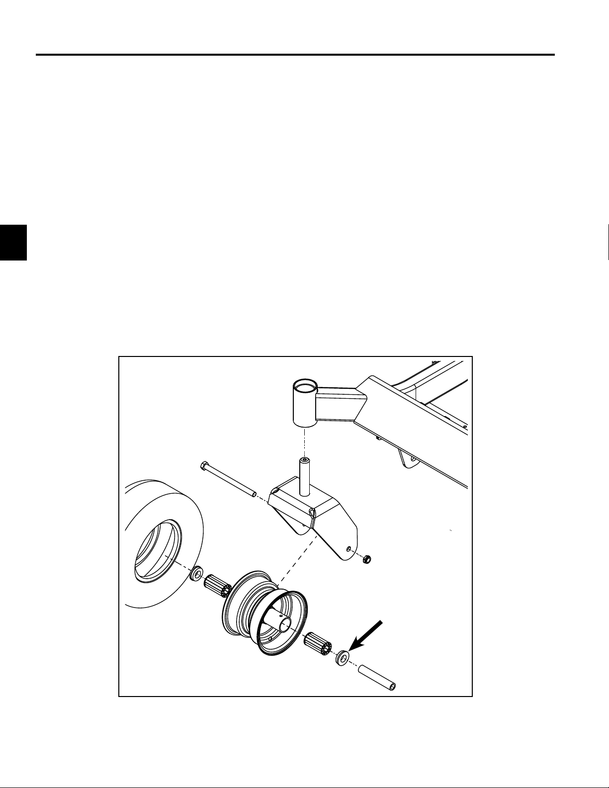
Caster Wheel, Bushing & Bearing Service – TITAN MX Chassis
Disassembly
1. Safely raise and support unit so front wheels are off
the ground.
2. Support under caster wheel and remove the nut /
bolt fastener (A).
3. Remove and inspect wheel spanner (B). Replace if
excessively worn.
4. Use an appropriate punch to remove the (2)
bushings (C) from the wheel hub. Inspect bushings
and replace if excessively worn.
5. Remove the (2) bearings (D) from the wheel hub.
Replace if excessively worn.
6. Properly clean and inspect the front wheel hub area.
Assembly
1. Lightly lubricate bearings (D), bushings (C) and
wheel spanner (B) with No. 2 general-purpose
lithium base grease. Fill center of wheel hub with
grease.
2. Install the (2) bearings (D) and (2) bushings (C) into
front wheel hub, making sure they are fully seated.
3. Install wheel spanner (B) into the front wheel
assembly.
4. Install front wheel assembly into the front caster.
5. Install the nut / bolt (A) and torque nut to
specication - 35 ft-lbs. (47 Nm).
6. Lubricate bushings / bearings through grease tting
with No. 2 general-purpose lithium base grease.
7. Safely lower unit and verify proper function.
(Fig. 007)
A
C
D
B
Fig. 007 PICT-2060
3-4
Toro TITAN 2009-2013 Service Manual
Page 31

CHASSIS
Pod / Fender Service
Pod / Fender Removal - RH
1. Raise seat and disconnect battery terminals.
2. Remove the (4) screws securing control panel (A) to
RH fender. Move control panel inward towards the
center of the unit.
3. Remove the (3) screws (B) securing the RH fender
to frame.
4. Maneuver RH fender up and off frame.
A
Pod / Fender Installation - RH
1. Maneuver RH fender into position.
2. Install the (3) screws (B) that secure the RH fender
to frame and torque to specication – 7 ft-lbs. (9
Nm).
3. Position control panel (A) back onto RH fender.
Install and sufciently tighten the (4) screws that
secure the control panel to the RH fender.
4. Verify choke cable, throttle cable and wiring are
properly routed.
3
5. Connect battery terminals and lower seat.
(Fig. 008).
B
B
B
Toro TITAN 2009-2013 Service Manual
Fig. 008 PICT-2061
3-5
Page 32

CHASSIS
3
Pod / Fender Removal - LH
1. Raise seat and disconnect battery terminals.
2. Remove the (3) screws (A) securing the LH fender to
the unit frame.
3. Lubricate rubber fuel tank neck grommet with soapy
water (Fig. 009).
Pod / Fender Installation - LH
1. Lubricate rubber fuel tank neck grommet with soapy
water.
2. Remove fuel cap from fuel tank.
3. Install LH fender assembly onto unit frame. Use care
while installing LH fender as the fuel tank neck slips
through the grommet.
4. Install fuel cap.
5. Install the (3) screws (A) that secure the fender to
the unit frame and torque to specications - 7 ft-lbs.
(9 Nm).
6. Connect battery terminals and lower seat.
(Fig. 010)
Fig. 009 PICT-2065
4. Remove fuel cap.
5. Lift LH fender assembly upward and off the frame.
Use care while lifting fender upward as the fuel tank
neck slips through the rubber grommet.
6. Reinstall fuel cap.
A
A
3-6
A
Fig. 010 PICT-2064
Toro TITAN 2009-2013 Service Manual
Page 33

CHASSIS
Fuel Tank Service
Fuel Tank Removal
1. Raise seat and disconnect battery terminals.
2. Remove LH pod / fender as shown in this chapter.
3. Remove the (2) bolts that secure the hydro
expansion tank (A) to the seat support. Move the
tank rearward for fuel tank removal clearance.
4. Remove the (1) fastener securing the fuel tank
retaining rod (B) and remove it from the chassis.
5. Remove the (2) thread-forming bolts that secure
the rear guard tube (C) to the seat support (E). OR
Remove the bolts / nuts securing the rear engine
guard to the ROPS frame (D).
(Fig. 011)
D
6. Remove the (2) bolts and nuts that secure the seat
support (E) to the frame brackets.
7. Note the location of and remove any cable ties /
loom clamps that secure wiring / cables to the seat
support bar (E).
8. Remove the seat support bar from the frame.
9. Disconnect and properly secure the fuel / vent line(s)
from the top of the fuel tank assembly.
10. The fuel tank is now loose and can be removed by
from the unit frame (Fig. 012).
3
A
C
B
C
E
Fig. 011 PICT-2070
E
Fig. 012 PICT-2066
Toro TITAN 2009-2013 Service Manual
3-7
Page 34

CHASSIS
3
Fuel Tank Installation
1. Position the fuel tank assembly into the unit frame.
2. Install the (2) bolts and nuts that secure the seat
support (E) to the frame brackets and torque to
specication – 17 ft-lbs. (23 Nm).
3. Install the fuel tank retaining rod (B) and torque
retaining bolt to specication – 8 ft-lbs. (11 Nm). Be
sure the front rod end is engaged into the control
box assembly (Fig. 013).
B
4. Install and sufciently tighten the (2) thread forming
bolts that secure the rear guard tube (C) to the seat
support (E). OR Install the bolts / nuts securing the
rear engine guard to the ROPS frame (D).
(Fig. 015)
D
C
Fig. 013 PICT-2069
A
C
B
E
Fig. 014 PICT-2066
Fig. 015 PICT-2070
5. Install the (2) bolts that secure the hydro expansion
tank (A) to the seat support and torque to
specication – 5 ft-lbs (7 Nm).
6. Properly route cables / wiring and reinstall cable ties
/ loom clams to secure them to the seat support.
7. Install LH pod / fender as outlined in this chapter.
8. Connect the battery cables and lower seat.
9. Verify proper function.
3-8
Toro TITAN 2009-2013 Service Manual
Page 35

CHASSIS
Motion Control Damper Service
Motion Control Damper Removal
1. Tilt seat forward and disconnect the battery.
2. Remove the appropriate fender / pod as shown in
this chapter.
3. Remove the (1) shoulder bolt (A) and washer that
secures the upper motion control damper eyelet to
the actuator arm.
4. Remove the nut and bolt (B) that secure the lower
motion control damper eyelet to the control box (Fig.
016).
A
B
Motion Control Damper Installation
1. Install the washer and upper damper eyelet to the
actuator arm and torque the shoulder bolt (A) to
specication – 7.5 ft-lbs. (10 Nm).
2. Install the lower damper eyelet to the Control Box
and torque the nut (B) to specication – 7.5 ft-lbs.
(10 Nm).
3. Install the fender / pod as shown in this chapter.
4. Check the motion control system for proper function.
(Fig. 017)
3
Fig. 016 PICT-2071
5. Remove the motion control damper from the unit.
A
B
Fig. 017 PICT-2072
Toro TITAN 2009-2013 Service Manual
3-9
Page 36

CHASSIS
3
Motion Control Box / Seat Pivot Service
Note: The entire Control Box / Motion Control
assembly does not need to be removed to
service the Actuator Arm assembly. The
Control Box is shown removed from the frame
for clarity and ease of service.
Motion Control Box / Seat Pivot Removal
1. Raise seat, disconnect battery terminals and remove
the battery from the unit.
2. Remove the (2) control handles.
3. Disconnect the seat switch harness connection and
remove seat switch harness from the routing clip on
the Motion Control Box.
4. Remove the operator’s seat:
Seat Style 1 - Remove the (2) retaining clips (A), seat
pivot rod (B), and seat from the unit (Fig. 018).
Seat Style 2 – Remove the (4) bolts and washers (C)
that attach the seat base to the rubber mounts (D)
(Fig. 019).
C
D
A
B
Fig. 018 PICT-2073
Fig. 019 PICT-2074
5. Remove the RH and LH fenders as shown in this
chapter.
6. Safely remove the fuel tank as shown in this chapter.
3-10
Toro TITAN 2009-2013 Service Manual
Page 37

CHASSIS
7. Remove the (2) control covers (E) (Fig. 020). 10. Remove the parking brake pin and washer (G).
Remove the parking brake link from the handle stud
(Fig. 022).
G
E
Fig. 020 PICT-2010
8. Make note of wire harness routing. Disconnect the
RH and LH neutral switches and the parking brake
switch. Open the loom routing clip and completely
remove harness from the Control Box.
9. Remove the motion control rod clips and pins (F)
(Fig. 021).
3
Fig. 022 PICT-2076
11. Remove the (4) fasteners (H) that secure the Control
Box to the frame (Fig. 023).
12. Remove the (2) nuts and (2) carriage bolts (I) that
secure the Control Box to the frame (Fig. 023).
H
F
Fig. 021 PICT-2075
Toro TITAN 2009-2013 Service Manual
I
Fig. 023 PICT-2084
3-11
Page 38

CHASSIS
3
13. Remove the (2) bolts/nuts (J) that secure the front
motion control box to the frame (Fig. 024).
J J
Fig. 024 PICT-2088
14. Remove the (2) fasteners that secure the oor pan
to the frame. Remove the oor pan.
15. The Motion Control Box is now loose and can be
removed from the frame.
Motion Control Box / Seat Pivot Installation
1. Install the control box / motion control assembly onto
the frame.
2. Install the (6) fasteners securing the control box
assembly to the frame and torque to specica tion:
• (H) (4) Bolts- 6 ft-lbs. (8 Nm)
• (I) (2) Carriage Bolt Fasteners - 17 ft-lbs. (23 Nm)
(Fig. 025)
H
I
Fig. 025 PICT-2084
3. Install the (2) bolts/nuts (J) that secure the front
motion control bolt to the frame and torque to
specication - 17 ft-lbs. (23 Nm) (Fig. 026).
J J
Fig. 026 PICT-2088
3-12
Toro TITAN 2009-2013 Service Manual
Page 39

CHASSIS
4. Install the oor pan and torque the (2) fasteners to
specication - 7 ft-lbs. (10 Nm).
5. Install the motion control rod and clips and pins (F)
(Fig. 027).
F
Fig. 027 PICT-2075
6. Install the parking brake linkage, washer and pin and
(G) (Fig. 028).
7. Properly route the wire harness and connect the RH
and LH neutral switches, and parking brake switch.
8. Install the control covers and torque the fasteners to
specication – 5 ft-lbs. (7 Nm).
9. Safely install the fuel tank as shown in this chapter.
10. Install the RH and LH fenders as shown in this
chapter.
11. Install the seat assembly.
12. Install the seat switch harness connection and verify
proper harness routing.
13. Install the (2) control handles and torque the (4)
fasteners to specication - 30 ft-lbs. (40 Nm).
14. Install the battery and battery cables.
15. Verify proper function.
3
G
Fig. 028 PICT-2076
Toro TITAN 2009-2013 Service Manual
3-13
Page 40

CHASSIS
3
Motion Control / Actuator Arm Service
Note: The entire Control Box / Motion control
assembly does not need to be removed
from the frame to service the Actuator Arm
assembly. The fenders and control box are
shown removed from the frame for clarity and
ease of service.
Motion Control Disassembly (LH Side Shown)
1. Remove the control lever.
2. Remove the upper damper shoulder bolt and washer
(A).
3. Note orientation, then remove the eccentric fastener
(B) and eccentric from the control box (Fig. 029).
A
4. Remove the actuator arm nut (C) and (2) washers
(Fig. 030).
5. Remove the shoulder bolt (D), actuator arm (E) and
the (2) washers from the activator arm (F) (Fig. 030).
C
E
D
Fig. 030 PICT-2082
6. Remove the activator arm pivot bolt and nut (G) and
the activator arm assembly (F) from the control box
(Fig. 031).
B
Fig. 029 PICT-2079
3-14
Toro TITAN 2009-2013 Service Manual
F
G
Fig. 031 PICT-2081
7. Inspect the pivot bolts, washers, nylon washers and
bushings for excessive wear, replace if necessary.
Page 41

CHASSIS
Motion Control Assembly
1. Install the activator arm assembly (F) into the control
box and torque the pivot bolt (G) to specication –
30 ft-lbs. (40 Nm). Do not apply lubrication to the
activator arm pivot bolt (G).
2. Apply anti-seize compound to the actuator arm
shoulder bolt (D) and the (4) washers. Install the
pivot bolt (D) through the activator arm (F).
3. Install the actuator arm pivot bolt (D) and (4)
washers to the activator arm assembly.
Be sure the (4) washers are positioned correctly:
• Washer 1: Standard Pivot Washer
• Washer 2: Standard Pivot Washer
• Washer 3: Standard Pivot Washer
• Washer 4: Teon Washer
(Fig. 032)
D
1
2
4. Apply Loctite
threads (D).
5. Tighten nut (C) until the control lever has an
acceptable and safe resistance feel when moved
from stop to stop.
- Over tightening nut (C) may damage the Teon
washer and cause excessive resistance.
- Under tightening nut (C) may cause the actuator
arm to feel loose.
(Fig. 033)
®
242 to the actuator arm pivot bolt
C
3
3
4
F
Fig. 032 PICT-2085
Fig. 033 PICT-2082
Toro TITAN 2009-2013 Service Manual
3-15
Page 42

CHASSIS
3
6. Install the upper motion control damper washer and
shoulder bolt (A) to the activator arm (F) and torque
to specication - 7.5 ft-lbs. (10 Nm).
7. Index and install the eccentric and fastener (B).
Torque nut to specication – 8ft-lbs. (11 Nm).
8. If needed, install the control box back onto the frame
as outlined in this chapter.
G
A
9. Install the control lever and torque the fasteners to
specication - 30 ft-lbs. (40 Nm).
10. Perform the “Neutral Adjustment” and “Tracking
Adjustment” procedures on pages 5-4 and 5-6.
(Fig. 034)
B
C
D
G
4
3
1
2
F
E
Fig. 034 PICT-2080
Washer 1 - Standard pivot washer
Washer 2 - Standard pivot washer
Washer 3 - Standard pivot washer
Washer 4 - Teon washer
3-16
Toro TITAN 2009-2013 Service Manual
Page 43

CHASSIS
Seat Support / Fender Support Service
Seat Support Removal
1. Raise seat and disconnect battery terminals.
2. Remove RH and LH pod / fender as shown in this
chapter.
3. Remove the (2) bolts that secure the hydro
expansion tank (A) to the seat support.
4. Remove the (1) fastener securing the fuel tank
retaining rod (B) to the seat support.
5. Remove the (2) thread-forming bolts that secure
the rear guard tube (C) to the seat support (E). OR
Remove the bolts / nuts securing the rear engine
guard to the ROPS frame (D) (Fig. 035).
D
6. Remove the (2) bolts and nuts that secure the seat
support (E) to the frame brackets.
7. Note the location of and remove any cable ties /
loom clamps securing wiring / cables to the seat
support bar (E).
8. Remove the seat support bar from the frame.
(Fig. 036)
A
C
3
B
E
Fig. 036 PICT-2066
C
E
Fig. 035 PICT-2070
Toro TITAN 2009-2013 Service Manual
3-17
Page 44

CHASSIS
3
Seat Support Installation
1. Position the Seat Support assembly into the unit
frame.
2. Install the (2) bolts and nuts that secure the seat
support (E) to the frame brackets and torque to
specication – 17 ft-lbs. (23 Nm).
3. Install the fuel tank retaining rod (B) and torque
retaining bolt to specication – 8 ft-lbs. (11 Nm). Be
sure the front rod end is engaged into the control
box assembly (Fig. 037).
9. Install and sufciently tighten the (2) thread forming
bolts that secure the rear guard tube (C) to the seat
support (E). OR Install the bolts / nuts securing the
rear engine guard to the ROPS frame (F) (Fig. 039).
C
B
Fig. 037 PICT-2069
A
C
B
E
Fig. 038 PICT-2066
Fig. 039 PICT-2070
4. Install the (2) bolts that secure the hydro expansion
tank (A) to the seat support and torque to
specication – 5 ft-lbs. (7 Nm).
5. Properly route cables / wiring and reinstall cable ties
/ loom clams to secure them to the seat support.
6. Install RH and LH pod / fender as outlined in this
chapter.
7. Connect the battery cables and lower seat.
8. Verify proper function.
3-18
Toro TITAN 2009-2013 Service Manual
Page 45

CHASSIS
Deck Lift Service
Deck Lift Removal
Note: Exploded view shown on next page, 3-20.
1. Remove the PTO belt tensioner spring, then remove
the PTO belt from the PTO clutch as shown in
chapter 6, page 6-5 - 6-8.
2. Remove the deck from the frame as shown in
Chapter 6, page 6-9 - 6-12.
3. Remove the deck lift foot petal center bolt, nut, and
spacer (A).
4. Remove the HOC lever pivot fastener and spacer
(B).
5. Remove the rear HOC arm fastener (C).
6. Remove the HOC plate and foot lift assembly from
the chassis.
Deck Lift Installation
1. Install the front and rear pivot rods (E and G) into the
frame slots and support in position.
2. Install the (4) pivot bushings, (4) gusset plates and
(8) fasteners that secure the pivot rods to the frame.
Torque the (8) fasteners to specication – 5 ft-lbs. (7
Nm) (Fig. 040).
3
7. 54 and 60 Inch Units Only - Remove the front lift pan
(D), spring, and mounting fasteners.
8. Support under the front foot lift pivot rod (E).Remove
the (4) fasteners (F) that retain the pivot bushings.
Remove the pivot rod from the frame. Inspect the (2)
bushings for wear and replace if necessary.
9. Support under the rear pivot rod (G). Remove the
(4) fasteners (H) that retain the pivot bushings.
Remove the pivot rod from the frame. Inspect the (2)
bushings for wear and replace if necessary.
10. Inspect the front lift pan (D), the front pivot rod
(E), the rear pivot rod (G) and all wear / pivot area
for excessive wear, bends and cracks. Replace if
necessary.
Fig. 040 PICT-2087
3. 54 and 60 Inch Units Only - Install the front lift pan
(D) and spring to the frame and torque fasteners to
specication - 50 ft-lbs. (69 Nm).
4. Install the rear HOC arm fastener (C). Do not tighten
at this time.
5. Install the HOC lever pivot fastener and spacer (B).
Do not tighten at this time.
6. Install the deck lift foot petal center bolt, nut, and
spacer (A).
7. Torque fasteners A, B and C to specication - 30 ftlbs. (40 Nm).
8. Install and level the deck as shown in Chapter 6.
9. Install and properly route the PTO belt, then install
the PTO belt tensioner spring.
(Fig. 041, next page)
Toro TITAN 2009-2013 Service Manual
3-19
Page 46

3
CHASSIS
C
C
A
B
A
H
E
D
G
F
Fig. 041 PICT-2068
3-20
Toro TITAN 2009-2013 Service Manual
Page 47

CHASSIS
Parking Brake & Linkage Service
Parking Brake & Linkage Removal
1. Tilt seat forward, disconnect and remove the battery.
2. Remove the LH control cover to access the parking
brake handle area.
3. Remove the parking brake pin and washer (A).
Remove the parking brake link from the handle stud
(Fig. 042).
4. Remove fastener (B) that secures the parking brake
handle to the control box assembly. Remove the
handle from the unit (Fig. 042).
A
B
5. Remove the brake return spring (C) and the clip and
washer (D) from the brake rod on the hydro (Fig.
043).
C
D
Fig. 043 PICT-2046
6. Remove all of the clips and washers (E), then
remove the (3) linkage rods from the chassis.
7. Remove the (2) cotter pins (F), (2) washers and
(2) bushings (G) from the brake bell crank (H) (Fig.
044).
3
Fig. 042 PICT-2076
F
Fig. 044 PICT-2083
8. Slide the brake bell crank (H) to one side and
remove the bell crank from the frame.
9. Inspect all linkage rods, pivot points and bushings
for excessive wear, replace if necessary.
Toro TITAN 2009-2013 Service Manual
3-21
Page 48

CHASSIS
3
Parking Brake & Linkage Installation
1. Position the brake bell crank (H) into the frame pivot
holes.
2. Install the pivot bushings (G), washers and cotter
pins to secure the bell crank into the frame.
3. Install the (3) linkage rods to the bell crank and
install retaining washers and clips (E), and (D).
4. Install the brake return spring (c) (Fig. 045).
C
D
5. Lubricate the brake handle pivot bolt (B) friction
surface with a light coating of engine assembly lube.
6. Install the parking brake handle into the motion
control box and torque the mounting fastener (B) to
specication – 17 ft-lbs. (23 Nm).
7. Install the parking brake linkage rod to the handle
stud using the washer and clip (A).
8. Install the LH control cover and torque the (1)
mounting fastener to specication - 5 ft-lbs. (7 Nm).
9. Install and connect the battery.
10. Inspect for proper brake function.
11. Verify proper parking brake function.
(Fig. 046)
Fig. 045 PICT-2046
E
B
Apply Thin Coating of Engine Assembly Lube
H
E
1”
Apply Thin Coating of Engine Assembly Lube
E
F
G
E
3-22
Fig. 046 PICT-2078
Toro TITAN 2009-2013 Service Manual
Page 49

ROPS Exploded View & Torque Values
(Fig. 047)
CHASSIS
3
D
D
ROPS mounting torque sequence:
1. Install, but do not tighten all ROPS mounting fasteners
2. Torque the (6) bolts (A) to specication – 35 ft-lbs. (47 Nm)
3. Torque the (4) bolts (B) to specication – 25 ft-lbs. (34 Nm)
4. Torque the (2) bolts (C) to specication – 75 ft-lbs. (101 Nm)
E
A
B
C
Fig. 047 PICT-2067
B
A
A
Torque values:
D. Seat Belt Mounting Fasteners – 75 ft-lbs. (101 Nm)
E. Rubber Bumper Mounting Fastener - 17 ft-lbs. (23 Nm)
Toro TITAN 2009-2013 Service Manual
3-23
Page 50

3
CHASSIS
THIS PAGE INTENTIONALLY LEFT BLANK.
3-24
Toro TITAN 2009-2013 Service Manual
Page 51

Engine Replacement
PTO Clutch & Clutch Stop Mounting (All Models)
(Fig. 048)
Kawasaki Clutch / Clutch Stop Location
ENGINE
4
Kohler / Briggs and Stratton Clutch / Clutch Stop Location
Fig. 048 PICT-2027
Toro TITAN 2009-2013 Service Manual
4-1
Page 52

4
ENGINE
Engine Mounting Exploded Views
Engine Mounting – Kawasaki Engine
(Fig. 049)
C
B
A
Fig. 049 PICT-2052
A. PTO clutch bolt - apply Loctite
B. Engine/clutch stop mounting bolts - Loctite 242 - 33 ft-lbs. (44 Nm)
C. Mufer to engine fastener - 13 ft-lbs. (17.5 Nm)
4-2
®
242 - 55 ft-lbs. (76 Nm)
Toro TITAN 2009-2013 Service Manual
Page 53

Engine Mounting – Kohler Engine
(Fig. 050)
ENGINE
C
4
B
A
Fig. 050 PICT-2053
A. PTO clutch bolt - apply Loctite® 242 - 55 ft-lbs. (76 Nm)
B. Engine/clutch stop mounting bolts - Loctite 242 - 33 ft-lbs. (44 Nm)
C. Mufer to engine fastener - 13 ft-lbs. (17.5 Nm)
Toro TITAN 2009-2013 Service Manual
4-3
Page 54

4
ENGINE
Engine Mounting – Briggs & Stratton Engine
(Fig. 051)
C
B
A
Fig. 051 PICT-2054
®
A. PTO clutch bolt - apply Loctite
B. Engine/clutch stop mounting bolts - Loctite 242 - 33 ft-lbs. (44 Nm)
C. Mufer to engine fastener - 13 ft-lbs. (17.5 Nm)
4-4
242 - 55 ft-lbs. (76 Nm)
Toro TITAN 2009-2013 Service Manual
Page 55

ENGINE
Engine Removal
1. Raise seat and disconnect battery terminals.
2. Safely raise and support rear of unit so rear wheels
are off the ground.
3. Remove PTO belt tensioner spring (A) from the deck
to relieve PTO belt tension as shown in chapter 6
(Fig. 052).
B
A
Fig. 052 PICT-2041
4. Remove PTO belt from PTO clutch.
11. Remove the (4) engine to frame mounting bolts.
Make note of clutch stop bracket (C) mounting and
orientation (Fig. 053).
C
Fig. 053 PICT-2055
12. Safely disconnect the fuel and vent lines from
engine.
13. Remove the throttle and choke cable from carburetor
linkage.
14. Disconnect the chassis-to-engine electrical
connection (D).
4
5. Disconnect the wire harness connection to the PTO
clutch.
6. Remove the PTO clutch bolt and then remove the
clutch from the engine crankshaft.
7. Remove the drive belt tensioner spring (B) (Fig.
052).
8. Remove the belt from around the crankshaft drive
pulley and remove the drive pulley from the engine
crankshaft. Make note of pulley orientation for
assembly.
9. If necessary, remove rear engine guard.
10. Remove the fasteners that secure the heat shield to
the mufer and frame and remove the heat shield. If
necessary, remove the mufer from the engine.
15. Disconnect the ground wires from the engine block
(E)
16. Disconnect the positive battery cable (F) from the
starter motor (Fig. 054).
F
D
E
Fig. 054 PICT-2056
17. The engine can now be lifted vertically from the
frame.
Toro TITAN 2009-2013 Service Manual
4-5
Page 56

ENGINE
4
Engine Installation
1. Position the engine onto the frame.
2. Connect the battery ground wires (E) to the engine
block, and connect the positive battery wire (F) to
the engine starter motor.
3. Connect the chassis to engine harness connector
(D) (Fig. 055).
F
D
E
11. Install the heat shield and mufer to frame mounting
screws and torque to specication - 17 ft-lbs. (23
Nm).
12. Apply anti-seize to the engine crankshaft and the
ends of the drive pulley shaft.
13. Install the drive pulley onto the crankshaft and hold
in position.
Note: The drive pulley is marked “CLUTCH SIDE”
for proper installation (Fig. 056).
Fig. 055 PICT-2056
4. Install the fuel and vent lines to the engine.
5. Install the throttle and choke cables to carburetor
linkage.
6. Apply Loctite® 242 to the (4) engine mounting bolts.
7. By hand, install the (4) engine mounting bolts.
Note: Some of the engine mounting bolts also
secure the clutch stop bracket and stiffener
tube to the frame. See the exploded views for
application and mounting location.
8. In a cross pattern, torque the (4) engine mounting
bolts to specication - 33 ft-lbs. (44 Nm).
9. Install mufer and new mufer gaskets, if necessary,
to the engine and torque mufer fasteners to
specication - 13 ft-lbs. (17.5 Nm).
Fig. 056 PICT-2044
14. Install the drive belt around the drive pulley.
15. Install the drive belt tensioner spring as oriented
below (Fig. 057).
10. Install heat shield to the mufer mounting screws
and torque to specication - 5 ft-lbs. (7 Nm).
4-6
Toro TITAN 2009-2013 Service Manual
Fig. 057 PICT-2041
Page 57

16. Apply Loctite® 242 to the PTO clutch bolt threads.
17. Install the PTO clutch onto crankshaft. Be sure PTO
clutch engages with the clutch stop bracket.
18. Install and torque the PTO clutch bolt to specication
– 55 ft-lbs. (76 Nm).
19. Install PTO belt onto PTO clutch. Verify proper PTO
belt routing; see PTO Belt Replacement and Belt
Routing” on page 6-5. Install the PTO belt tensioner
spring to the deck.
20. Connect battery cables and verify engine oil level.
21. Safely start engine and verify proper operation.
ENGINE
4
Toro TITAN 2009-2013 Service Manual
4-7
Page 58

4
ENGINE
THIS PAGE INTENTIONALLY LEFT BLANK.
4-8
Toro TITAN 2009-2013 Service Manual
Page 59

Hydrostatic Drive Exploded Views
(Fig. 058)
HYDROSTATIC DRIVE SYSTEM
5
Toro TITAN 2009-2013 Service Manual
Fig. 058 PICT-2038
5-1
Page 60

HYDROSTATIC DRIVE SYSTEM
Hydrostatic Drive Belt Routing
(Fig. 059)
5
Bottom View
Rear View
5-2
Fig. 059 PICT-2039
Toro TITAN 2009-2013 Service Manual
Page 61

HYDROSTATIC DRIVE SYSTEM
Hydro-Gear ZT-2800 & ZT-3100 Hydrostatic Transaxles
Fig. 060 PICT-1002
Lubrication Toro HYPR-OIL® 500 or 20w50 Engine Oil
Oil Capacity ZT-2800 77.23 . oz. (2284ml) each
Oil Level Check Check expansion reservoir and if necessary add the specied oil to the FULL COLD
line. See illustration below. Also see the Hydro-Gear ZT-2800 / ZT-3100 service manual
(BLN-52441).
Fluid Change Interval After the First 50 hours - change the oil and lters for the hydraulic system and bleed
the system.
Every 400 Hours - change the oil and lters for the hydraulic system and bleed the
system.
5
Checking the Hydraulic Oil Level
C
A
B
Fig. 061 g. 51 G020323
A. Expansion tank C. Engine
B. Full cold line
Toro TITAN 2009-2013 Service Manual
5-3
Page 62

HYDROSTATIC DRIVE SYSTEM
Neutral Adjustment
Note: Do not make neutral adjustments on cold
hydrostatic drive systems. Safely warm the
drive system before making adjustments.
1. Safely raise and support unit so rear wheels are off
the ground.
2. Unplug the seat switch and install a jumper wire
across the harness terminals.
Note: Jumping the seat switch is for testing /
adjustment procedures only.
(Fig. 062)
5. Release the parking brake and observe rear tire
movement. If the tire is creeping in either forward or
reverse, a neutral adjustment is required.
Note: A slight amount of reverse creep is
acceptable.
(Fig. 063)
Fig. 063 PICT-6486a
5
Fig. 062 PICT-6459a
3. Start the engine and run at full RPM.
4. Verify the motion control handles are in the outward
neutral position.
6. Turn engine off.
7. Remove the fender / pod assembly / control panel of
the side that needs neutral adjustment as shown in
chapter 3.
(Fig. 064)
Fig. 064 PICT-6483
5-4
Toro TITAN 2009-2013 Service Manual
Page 63

HYDROSTATIC DRIVE SYSTEM
8. Remove the hairpin and clevis from the adjustable
yoke (Fig. 065).
Fig. 065 PICT-6471a
9. Loosen the jam nut on the hydro linkage rod (Fig.
066).
10. Turn the yoke assembly to lengthen / shorten the
control rod as needed to achieve proper neutral
adjustment (Fig. 067).
Fig. 067 PICT-6478a
11. Install the clevis pin and hairpin back into the yoke
assembly.
Fig. 066 PICT-6474a
12. Start the engine and run it at full RPM.
13. Stroke the control handles in forward and reverse.
Move the control into the neutral position and verify
the rear wheels do not rotate forward or reverse.
Note: A slight amount of reverse creep is
acceptable.
14. Turn engine off.
15. Readjust neutral setting if required.
16. Install the fender / pod assembly / control panel
assembly as shown in chapter 3.
17. Remove the seat switch bypass jumper wire and
reconnect the seat switch harness connection.
18. Safely lower the unit and verify proper drive system
function.
5
Toro TITAN 2009-2013 Service Manual
5-5
Page 64

HYDROSTATIC DRIVE SYSTEM
Tracking Adjustment
Note: Do not make tracking adjustments on cold
hydrostatic drive systems. Safely warm the
drive system before making adjustments.
- Adjust the eccentric on the LEFT side if the unit
pulls to the RIGHT
- Adjust the eccentric on the RIGHT side in the unit
pulls to the LEFT.
1. Remove the (1) bolt that secures the control panel
cover to access the adjustment eccentric (Fig. 068).
(RH side shown)
2. Hold the pivot bolt in position with a 1/4” hex wrench,
and then slightly loosen the eccentric pivot nut (A)
(Fig. 069).
A
Fig. 069 PICT-6488
3. Use a 1/4” hex wrench to adjust the eccentric pivot
bolt until the unit tracks straight (Fig. 070).
5
Fig. 068 PICT-2040
Fig. 070 PICT-6495
4. After proper tracking has been achieved, hold
the pivot bolt in position with a 1/4” hex wrench,
and then torque the eccentric pivot nut (A) to
specication – 8 ft-lbs. (11 Nm).
5. Install the control panel cover, then torque the
retaining bolt to specication – 4.5 ft-lbs. (6 Nm).
6. Verify proper drive system function.
5-6
Toro TITAN 2009-2013 Service Manual
Page 65

HYDROSTATIC DRIVE SYSTEM
Purging Procedure
Due to the effects air has on efciency in hydrostatic
drive applications, it is critical that it is purged from the
system.
This purge procedure should be implemented any time
a hydrostatic system has been opened to facilitate
maintenance, any additional oil has been added to the
system, or a replacement transaxle has been installed.
Air creates inefciency because its compression and
expansion rate is higher than that of the oil in hydrostatic
drive systems.
The resulting symptoms of air in hydrostatic systems
may be:
• Noisy operation
• Lack of power or drive after short term operation.
• High operation temperature and excessive
expansion of “oil”; in the latter case, oil may
overow.
The following procedure should be performed with the
drive wheels off the ground and then repeated under
operating conditions.
1. With the bypass valve open (push position) and the
engine running, slowly move the control handles
(forward/reverse levers) in both forward and reverse
directions 5 to 6 times; as air is purged from the
transaxles, the oil level will drop.
2. With the bypass valves in the closed position (drive
position) and the engine running, slowly move
the control handles in both forward and reverse
directions 5 to 6 times.
3. It may be necessary to repeat steps 1 and 2 until
all air is completely purged from the transaxles.
When the transaxles move forward at normal speed,
purging is complete.
5
Toro TITAN 2009-2013 Service Manual
5-7
Page 66

HYDROSTATIC DRIVE SYSTEM
Hydrostatic Drive Belt Replacement
Hydrostatic Drive Belt Removal
1. Safely raise and support unit so rear wheels are off
the ground.
2. Remove PTO belt tensioner spring (A) from the deck
to relieve PTO belt tension as shown in chapter 6
(Fig. 071).
B
A
11. Inspect the idler arm / tensioner pivot and pulley
bearings for excessive wear and replace if
necessary (Fig. 072).
F
5
Fig. 071 PICT-2041
3. Remove PTO belt from PTO clutch.
4. Disconnect the wire harness connection to the PTO
clutch.
5. Remove the PTO clutch bolt and then remove the
clutch from the engine crankshaft.
6. Remove the drive belt tensioner spring (B) (Fig.
071).
7. Remove the belt from around the crankshaft drive
pulley then remove the drive pulley from the engine
crankshaft. Make note of pulley orientation for
assembly.
8. Disengage the drive belt from the tensioner pulley
and idler pulley.
9. Remove the belt from around both hydro input
pulleys. Do not bend or damage the hydro cooling
fans while walking the belt upward off the input
pulleys.
E
D
G
F
E
D
C
F
Fig. 072 PICT-2042
C. Washer E. Spacer
D. Friction washer - F. 30 ft-lbs. (40 Nm)
composite G. Arm
10. Remove the belt from the unit and inspect. Replace
if necessary.
5-8
Toro TITAN 2009-2013 Service Manual
Page 67

HYDROSTATIC DRIVE SYSTEM
Kawasaki Clutch / Clutch Stop Location
Hydrostatic Drive Belt Installation
1. Properly route the belt around the (2) hydro input
pulleys, and (2) tensioner / idler pulleys (Fig. 073).
Fig. 073 PICT-2043
2. Install the drive pulley onto the crankshaft and hold
in position.
Note: The drive pulley is marked “CLUTCH SIDE”
for proper installation (Fig. 074).
3. Install the drive belt around the drive pulley.
4. Install the drive belt tensioner spring as oriented
below (Fig. 075).
Fig. 075 PICT-2041
5. Apply Loctite® 242 to the PTO clutch bolt threads.
6. Install the PTO clutch. Be sure the PTO clutch stop
bracket is properly engaged into the clutch slot (Fig.
076).
5
Fig. 074 PICT-2044
Toro TITAN 2009-2013 Service Manual
Kohler / Briggs and Stratton Clutch / Clutch Stop Location
Fig. 076 PICT-2045
5-9
Page 68

HYDROSTATIC DRIVE SYSTEM
7. Torque the clutch bolt to specication - 55 ft-lbs. (75
Nm).
8. Install the PTO belt around the PTO clutch pulley.
9. Verify proper PTO belt routing and then install the
PTO belt tensioner spring to the deck. See PTO Belt
Replacement and Belt Routing on page 6-5.
10. Safely lower unit and verify proper drive system
function.
Transaxle Replacement
Transaxle Removal – RH Side Shown
1. Disconnect the battery terminals.
2. Safely raise and support rear of unit so rear wheels
are off the ground.
3. Remove the rear wheels.
4. Remove the parking brake return spring (A) from the
rod and spring plate.
5. Remove the retaining pin (B) from the brake linkage
then remove the brake rod from the hydro arm.
6. Remove the hydro bypass rod (C), retaining clip, and
washer then remove the rod from the unit.
7. Remove the hydro control rod nut and bolt (D) (Fig.
077).
5
D
C
A
B
Fig. 077 PICT-2046
5-10
Toro TITAN 2009-2013 Service Manual
Page 69

HYDROSTATIC DRIVE SYSTEM
8. Remove the drive belt tensioner spring (Fig. 078). 11. Remove the (2) bolts that secure hydro center
support. Remove support from the unit (Fig. 080).
Fig. 078 PICT-2041
Fig. 080 PICT-2048
9. Slip the drive belt off the idler / tensioner pulleys,
then off the appropriate hydro input pulley.
10. Disconnect and plug the hydro reservoir hoses at the
hydro tting. Be sure to capture and dispose of uid
and shop towels properly (Fig. 079).
12. Safely support hydro assembly in current position
using a hydraulic oor jack. Remove the (2) outer
hydro mounting fasteners (Fig. 081).
Fig. 079 PICT-2047
5
Fig. 081 PICT-2049
Toro TITAN 2009-2013 Service Manual
5-11
Page 70

HYDROSTATIC DRIVE SYSTEM
13. Remove the (1) front hydro mount fastener (Fig.
082).
Fig. 082 PICT-2050
14. Remove the (1) rear hydro mounting fastener (Fig.
083).
Transaxle Installation
1. Position the hydro assembly up into the unit frame
and align mounting points.
2. Apply Loctite® 242 to the (2) hydro center support
bolts.
3. Loosely install ALL hydro mounting spacers, fasteners and center support bolts. Do not fully tighten
at this time.
4. Torque hydro mounting fasteners in sequence to
specication and shown:
1st – Apply Loctite 242 to the hydro center support
bolts. Torque bolts to specication – 17 ft-lbs. (23
Nm) (Fig. 084).
5
Fig. 084 PICT-2048
Fig. 083 PICT-2051
15. Lower the hydro assembly then remove it from the
frame.
5-12
Toro TITAN 2009-2013 Service Manual
Page 71

HYDROSTATIC DRIVE SYSTEM
2nd - Torque the (1) front hydro mount fastener to
specication – 17 ft-lbs. (23 Nm) (Fig. 085).
Fig. 085 PICT-2050
3rd – Torque the (1) rear hydro mount fastener to
specication – 17 ft-lbs. (23 Nm) (Fig. 086).
4th – Torque the (2) outside hydro mount fasteners
to specication – 17 ft-lbs. (23 Nm) (Fig. 087).
Fig. 087 PICT-2049
5. Connect the hydro reservoir hoses at the hydro
tting (Fig. 088).
Fig. 086 PICT-2051
5
Fig. 088 PICT-2047
Toro TITAN 2009-2013 Service Manual
5-13
Page 72

HYDROSTATIC DRIVE SYSTEM
6. Install the hydro drive belt and verify proper routing
(Fig. 089).
Fig. 089 PICT-2043
7. Install and orient the drive belt tensioner spring as
shown (Fig. 090).
8. Install the parking brake return spring (A).
9. Install the brake rod into the hydro arm and insert
the retaining pin (B).
10. Install the hydro bypass rod, washer and retaining
clip (C).
11. Install the hydro control rod nut and bolt (D) and
torque to specication - 17 ft-lbs. (23 Nm) (Fig. 091).
D
C
A
B
5
Fig. 090 PICT-2041
Fig. 091 PICT-2046
12. Install the rear wheels and torque lug nuts to
specication – 80 ft-lbs. (108 Nm).
13. Connect battery terminals.
14. Safely lower unit.
15. Add 20w50 engine oil or Toro HYPR-OIL® 500 to the
hydro reservoir FULL COLD mark.
16. Perform the purging procedure as shown in this
chapter.
17. Perform the neutral and tracking adjustment
procedures as shown in this chapter.
18. Verify proper unit oil levels and function.
5-14
Toro TITAN 2009-2013 Service Manual
Page 73

Mower Deck Exploded Views
48 Inch Deck
(Fig. 092)
MOWER DECK
D
D
INTL. ONLY
C
E
6
B
A
A. Blade bolt - 105 ft-lbs. (143 Nm)
B. Washer - concave side towards blade
C. Pulley Nut - 105 ft-lbs. (143 Nm)
Toro TITAN 2009-2013 Service Manual
Fig. 092 PICT-2028 48
D. 30 ft-lbs. (40 Nm)
E. Spindle housing-to-deck bolts - 14 ft-lbs. (19 Nm)
6-1
Page 74

MOWER DECK
50 Inch Deck
(Fig. 093)
D
D
D
C
E
6
A. Blade bolt - 55 ft-lbs. (76 Nm)
B. Washer - concave side towards blade
C. Pulley Nut - 55 ft-lbs. (76 Nm)
INTL. ONLY
B
A
Fig. 093 PICT-2028 50
D. 30 ft-lbs. (40 Nm)
E. Spindle housing-to-deck bolts - 17 ft-lbs. (23 Nm)
6-2
Toro TITAN 2009-2013 Service Manual
Page 75

54 Inch Deck
(Fig. 094)
MOWER DECK
D
D
C
INTL. ONLY
E
6
B
A
Fig. 094 PICT-2028 54
A. Blade bolt - 105 ft-lbs. (143 Nm)
B. Washer - concave side towards blade
C. Pulley Nut - 105 ft-lbs. (143 Nm)
Toro TITAN 2009-2013 Service Manual
D. 30 ft-lbs. (40 Nm)
E. Spindle housing-to-deck bolts - 14 ft-lbs. (19 Nm)
6-3
Page 76

MOWER DECK
60 Inch Deck
(Fig. 095)
6
D
D
C
E
A. Blade bolt - 105 ft-lbs. (143 Nm)
B. Washer - concave side towards blade
C. Pulley Nut - 105 ft-lbs. (143 Nm)
6-4
B
A
Fig. 095 PICT-2028 60
D. 30 ft-lbs. (40 Nm)
E. Spindle housing-to-deck bolts - 14 ft-lbs. (19 Nm)
Toro TITAN 2009-2013 Service Manual
Page 77

MOWER DECK
PTO Belt Replacement and Belt Routing
48, 54, 60 Inch Deck Idler / Tensioner Pulley
(Fig. 096)
E
B
B
E
B
C
A
50 Inch Deck Idler / Tensioner Pulley
(Fig. 097)
E
B
B
C
E
A
B
D
Fig. 096 PICT-2030
A. PTO Belt D. PTO Clutch Pulley
B. Spindle Pulley E. Idler
C. PTO Belt Tensioner
D
Fig. 097 PICT-2031
A. PTO Belt D. PTO Clutch Pulley
B. Spindle Pulley E. Idler
C. PTO Belt Tensioner
6
Toro TITAN 2009-2013 Service Manual
6-5
Page 78

MOWER DECK
Inspecting the Belts
Service Interval: Every 25 hours – Check the belts for
wear.
Check the belts for cracks, frayed edges, burn marks or
any other damage. Replace damaged belts.
PTO Belt Replacement - 48, 54 and 60 Inch Deck
Squealing when the belt is rotating, blades slipping when
cutting grass, frayed belt edges, burn marks and cracks
are signs of a worn mower belt. Replace the mower belt
if any of these conditions are evident.
1. Disengage the PTO switch, move the motion control
levers to the neutral locked position and set the
parking brake.
2. Stop the engine, remove the key, and wait for all
moving parts to stop before leaving the operating
position.
3. Lower the mower to the 3 inch (76mm) height-of-cut
position.
4. Remove the belt covers (Fig. 098).
A
B
6
C
Fig. 098 g. 67 G015789
A. Loosen the screws C. Remove belt cover
B. Pivot the belt cover up
6-6
Toro TITAN 2009-2013 Service Manual
Page 79

MOWER DECK
5. Using a spring tool, (Toro part no. 92-5771), remove
the idler spring from the deck post to remove tension
on the idler pulley (Fig. 099).
B
A
C
D
E
9. Using a spring tool, (Toro part no. 92-5771), install
the idler spring over the deck post and placing tension on the idler pulley and mower belt (Fig. 099).
10. Ensure that the belt is properly seated in all pulleys.
11. Install the belt covers (Fig. 100).
A
B
C
Fig. 099 g. 68 G009806
A. Spring tool D. Idler/Tensioner arm
B. Idler/Tensioner spring E. PTO belt
C. Deck spring post
6. Lower the mower to the lowest height-of-cut. Place
the height-of-cut pin in the lock position for lowest
height-of-cut.
7. Remove the belt from the spindle pulleys and PTO
clutch.
8. Install the new belt around the spindle pulleys and
the PTO clutch pulley under the engine (Fig. 099).
WARNING
! !
The spring is under tension when installed and can
cause personal injury.
Be careful when removing the belt.
Fig. 100 g. 69 G015790
A. Position the belt cover, ensure the tabs seat
B. Pivot the belt cover down
C. Tighten the screws
6
Toro TITAN 2009-2013 Service Manual
6-7
Page 80

MOWER DECK
PTO Belt Replacement - 50 Inch Deck
Squealing when the belt is rotating, blades slipping when
cutting grass, frayed belt edges, burn marks and cracks
are signs of a worn mower belt. Replace the PTO belt if
any of these conditions are evident.
1. Park the machine on a level surface and disengage
the blade control switch.
2. Move the motion control levers outward to the
neutral lock position, set the parking brake, stop the
engine, remove the key, and wait for all moving parts
to stop before leaving the operating position.
3. Lower the mower to the 3 inch (76 mm) height-ofcut.
4. Remove the belt covers over the outside spindles.
5. If necessary, remove the oor pan to access the idler
pulley.
6. Using a spring tool, (Toro part no. 92-5771), remove
the idler spring from the deck hook to remove
tension on the idler pulley and roll the belt off of the
pulleys (Fig. 101).
WARNING
! !
B
E
B
C
E
B
A
D
Fig. 101 PICT-2031
A. PTO Belt D. PTO Clutch Pulley
B. Spindle Pulley E. Idler
C. PTO Belt Tensioner
6
The spring is under tension when installed and can
cause personal injury.
Be careful when removing the belt.
7. Route the new belt around the engine PTO pulley
and spindle pulleys (Fig. 101).
8. Using a spring tool, (Toro part no. 92-5771), install
the idler spring over the deck hook and placing
tension on the idler pulley and mower belt route the
belt onto the idler pulley (Fig. 101).
9. Ensure that the belt is properly seated in all pulleys.
10. Install the belt covers over the outside spindles.
6-8
Toro TITAN 2009-2013 Service Manual
Page 81

MOWER DECK
Mower Deck Replacement
Mower Deck Removal - 48 and 54 Inch Deck
1. Park the machine on a level surface and disengage
PTO switch.
2. Move the motion control levers outward to the
neutral position and engage parking brake.
3. Stop the engine, remove the key, and wait for all
moving parts to stop before leaving the operating
position.
4. Lower the mower to the 3 inch (76mm) height-of-cut
position.
5. Remove the PTO belt tensioner spring and remove
the PTO belt from the engine pulley.
6. Lower the mower to the lowest height-of-cut.
7. Move the spring loaded J-hooks out of the slot in the
rear hanger brackets on both sides of the deck (Fig.
102).
8. Remove the hardware from the front deck hangers
on both sides of the deck (Fig. 103).
A
B
E
F
C
G
D
Fig. 103 g. 71 G010304
A
B
C
Fig. 102 g. 70 G010311
A. Deck hanger E. Rear hanger bolts
B. Hairpin F. J-hook
C. Washer G. Rear deck hanger
D. Welded post on deck bracket
6
9. Carefully lift the deck off the rear hanger bolts and
lower the front of the mower deck to the ground.
10. Raise the height-of-cut to the transport position.
11. Slide the mower out from underneath the machine.
Toro TITAN 2009-2013 Service Manual
6-9
Page 82

MOWER DECK
Mower Deck Installation - 48 and 54 Inch Deck
1. Slide the deck under the machine.
2. Lower the height-of-cut lever to the lowest position.
Place the height-of-cut pin in the lock position for
lowest height-of-cut.
3. Lift the rear of the mower deck and guide the hanger
brackets over the rear hanger bolts.
4. Attach the front support on the mower deck to the
front deck hangers and secure them with a washer
and hairpin (Fig. 104).
A
B
E
F
C
G
Mower Deck Removal - 60 Inch Deck
1. Park the machine on a level surface and disengage
PTO switch.
2. Move the motion control levers outward to the
neutral position and engage parking brake.
3. Stop the engine, remove the key, and wait for all
moving parts to stop before leaving the operating
position.
4. Lower the mower to the 3 inch (76mm) height-of-cut
position.
5. Remove the PTO belt tensioner spring and remove
the PTO belt from the engine pulley.
6. Remove the hairpin and washer securing the long,
link bar to the frame and deck; remove the link bar
(Fig. 105).
B
6
D
Fig. 104 g. 71 G010304
A. Deck hanger E. Rear hanger bolts
B. Hairpin F. J-hook
C. Washer G. Rear deck hanger
D. Welded post on deck bracket
5. Properly route and install the PTO belt and tensioner
spring.
C
A
Fig. 105 g. 72 G010309
A. Hairpin C. Washer
B. Link bar
6-10
Toro TITAN 2009-2013 Service Manual
Page 83

MOWER DECK
7. Remove the hardware from the front and rear deck
hangers on both sides of the deck (Fig. 106).
A
B
A
B
C
D
C
D
Mower Deck Installation - 60 Inch Deck
1. Slide the mower under the machine.
2. Lower the height-of-cut lever to the lowest position.
Place the height-of-cut pin in the lock position for
lowest height-of-cut.
3. Lift the rear of the mower deck and attach the
rear support on the mower deck to the rear deck
hangers. Secure them with a washer and hairpin.
4. Attach the front support on the mower deck to the
front deck hangers and secure them with a washer
and hairpin (Fig. 106).
5. Install the long, link bar through the frame hanger
and deck. Secure the link bar with the hairpin and
washers removed previously (Fig. 107).
B
Fig. 106 g. 73 G010305
A. Deck hanger C. Washer
B. Hairpin D. Welded post on deck
8. Raise the height-of-cut to the transport position.
9. Slide the mower out from underneath the machine.
C
A
6
Fig. 107 g. 72 G010309
A. Hairpin C. Washer
B. Link bar
6. Properly route and install the PTO belt, then install
tensioner spring.
Toro TITAN 2009-2013 Service Manual
6-11
Page 84

MOWER DECK
Mower Deck Removal - 50 Inch Deck
1. Park the machine on a level surface and disengage
the blade control switch.
2. Move the motion control levers outward to the
neutral position, engage parking brake, stop the
engine, remove the key, and wait for all moving parts
to stop before leaving the operating position.
3. Lower the mower to the 3 inch (76mm) height-of-cut
position.
4. Remove the PTO belt tensioner spring, then remove
PTO belt from PTO clutch.
5. Lower the height-of-cut lever to the lowest position.
6. Move the spring loaded J-hooks out of the slot in the
rear hanger brackets on both sides of the deck (Fig.
108).
A B
7. Remove the hardware from the front deck hangers
on both sides of the deck (Fig. 109).
A
B
E
F
C
G
D
6
C
Fig. 108 g. 70 G010311
Fig. 109 g. 67 G010303
A. Deck hanger E. Rear hanger bolts
B. Hairpin F. J-hook
C. Washer G. Rear deck hanger
D. Welded post on deck bracket
8. Carefully lift the deck off the rear hanger bolts and
lower the front of the mower deck to the ground (Fig.
109).
9. Raise the height-of-cut to the transport position
10. Slide the mower out from underneath the machine.
6-12
Toro TITAN 2009-2013 Service Manual
Page 85

Mower Deck Installation - 50 Inch Deck
1. Slide the mower under the machine.
2. Lower the height-of-cut lever to the lowest position.
Place the height-of-cut pin in the lock position for
lowest height-of-cut.
3. Lift the rear of the mower deck and guide the hanger
brackets over the rear hanger bolts (Fig. 110).
4. Attach the front support on the mower deck to the
front deck hangers and secure them with a clevis pin
and hairpin (Fig. 110).
A
MOWER DECK
B
E
F
C
G
D
Fig. 110 g. 67 G010303
A. Deck hanger E. Rear hanger bolts
B. Hairpin F. J-hook
C. Washer G. Rear deck hanger
D. Welded post on deck bracket
6
5. Properly route PTO belt around deck pulleys and
PTO clutch, then install the idler/tensioner spring.
Toro TITAN 2009-2013 Service Manual
6-13
Page 86

MOWER DECK
Spindle Service
Spindle Removal
1. If necessary, remove deck from chassis as outlined
in this chapter.
2. Remove belt cover(s) from deck.
3. Remove the PTO belt tensioner spring and
disengage the PTO belt from the spindle pulley(s).
4. Safely hold the blade in position and remove the
spindle pulley nut (A). Inspect the pulley and spindle
shaft for excessive wear and replace if necessary.
5. Remove the fasteners that secure spindle housing to
deck shell.
- 48, 54 and 60 inch decks use (6) thread forming
bolts for spindle mounting
- 50 inch decks use (4) thread forming bolts for
spindle mounting
6. Remove spindle assembly from deck.
7. Remove blade bolt (B) and washer.
8. Remove blade.
Spindle Installation
1. Install blade and washer onto spindle shaft. Install
and torque blade bolt to specication:
Note: Install blade washer so concave surface is
towards blade.
- 48, 54 and 60 inch decks – 105 ft-lbs. (143 Nm)
- 50 inch decks - 55 ft-lbs (76 Nm)
2. Install spindle assembly onto the deck shell and
torque fasteners (C) to specication:
- 48, 54 and 60 inch decks - 14 ft-lbs. (19 Nm)
- 50 inch decks - 17 ft-lbs. (23 Nm)
3. Safely hold blade in position.
4. Install spindle pulley onto the spindle shaft and
torque pulley nut (A) to specication:
- 48, 54 and 60 inch decks – 105 ft-lbs. (143 Nm)
- 50 inch decks - 55 ft-lbs. (76 Nm)
5. If necessary, install deck onto the chassis.
6. Properly route PTO belt, then install the PTO belt
tensioner spring.
6
B
48, 54 and 60 Inch Decks
7. Install belt cover(s) onto deck and sufciently tighten
mounting bolts.
8. Safely verify proper function.
(Fig. 111)
A A
C
C
B
50 Inch Decks
Fig. 111 PICT-2034
6-14
Toro TITAN 2009-2013 Service Manual
Page 87

Spindle Exploded Views
Spindle Assembly - 48, 54 and 60 Inch Deck
(Fig. 112)
MOWER DECK
A
B
C
A
Spindle Assembly - 50 Inch Deck
(Fig. 113)
A
C
B
A
Fig. 112 PICT-2033
C
A
B
A
A
B
C
A
Fig. 113 PICT-2032a
A. Bearing C. Spindle housing
B. Bearing spacer
6
Toro TITAN 2009-2013 Service Manual
6-15
Page 88

MOWER DECK
Spindle Disassembly
1. If necessary, remove deck from the frame as shown
in this chapter.
2. Remove spindle assembly from deck as outlined in
this chapter.
3. Remove spindle shaft (D) from spindle assembly.
Inspect for excessive wear and replace if necessary
(Fig. 114).
4. Use an appropriate punch or bearing extractor
to remove the (2) bearings (A) from the spindle
housing.
5. Inspect bearing spacer (B) for wear and replace if
necessary.
6. Clean and inspect spindle housing (C) bearing bores
for excessive wear and replace if necessary.
C
Spindle Assembly
1. Fully seat a new UPPER bearing (pulley side) into
spindle housing until it contacts the bearing bore
shoulder. Be sure to press equally on inner and
outer race while installing bearing.
2. Turn spindle housing over.
3. Install the bearing spacer (B) into spindle housing
(C).
4. Install a new LOWER bearing (blade side) into
spindle housing until it contacts bearing spacer and/
or bore shoulder. Be sure to press equally on the
inner and outer race while installing bearing.
Note: While installing lower bearing, align center
bore of the bearing spacer(s) with center bore
of the bearings.
5. Install spindle shaft (D) into spindle housing.
6. Install spindle assembly to the deck as outlined in
this chapter.
6
D
Fig. 114 PICT-2035
7. If necessary, install the deck onto the frame.
(Fig. 115)
A
B
C
6-16
A
Fig. 115 PICT-2063
Toro TITAN 2009-2013 Service Manual
Page 89

Idler Arm / Deck Belt Tensioner Service
Idler Arm / Tensioner Exploded Views
Idler Arm / Tensioner - 48, 54, 60 Inch Deck
(Fig. 116)
MOWER DECK
D
A
B
D
C
B
A
6
A
Toro TITAN 2009-2013 Service Manual
Fig. 116 PICT-2037
A. Washer C. Spacer
B. Friction washer - D. 30 ft-lbs. (40 Nm)
(composite)
6-17
Page 90

MOWER DECK
Idler Arm / Tensioner - 50 Inch Deck
(Fig. 117)
D
A
B
D
C
B
A
6
Fig. 117 PICT-2036
A. Washer C. Spacer
B. Friction washer - D. 30 ft-lbs. (40 Nm)
(composite)
6-18
Toro TITAN 2009-2013 Service Manual
Page 91

MOWER DECK
Idler Arm Inspection
1. Remove deck belt as shown in this chapter.
2. Remove deck if necessary, as outlined in this
chapter.
3. Rotate idler arm by hand. The idler arm should not
pivot freely, it should take some force to rotate the
idler arm.
- If the idler arm rotates easily and / or rocks
excessively side-to-side, replace mounting
hardware, spacers and all washers.
4. Inspect idler arm pulley bearing and replace if
necessary.
Idler Arm Removal
1. Remove deck belt as shown in this chapter.
2. Remove deck if necessary.
3. Remove idler arm/tensioner spring from idler arm.
Inspect spring and replace if necessary.
Idler Arm Installation
1. Install idler pulley to the idler arm and torque
mounting bolt to specication - 30 ft-lbs. (40 Nm).
2. Assemble the idler arm pivot washers, spacers and
bolts. Verify proper component order according the
exploded views.
3. Install idler arm assembly and pivot bolt onto the
deck and torque to specication – 30 ft-lbs. (40 Nm).
4. Install deck to the frame if needed.
5. Fully install deck belt and tensioner spring to idler
arm.
6. Safely operate unit and check for proper function.
4. Remove the (1) fastener that secures idler arm
assembly to deck.
5. Inspect pivot bolt, friction washers, standard
washers, spacers and replace if necessary.
6. Remove the fastener that secures idler pulley to the
idler bracket. Inspect pulley bearing and replace if
necessary.
6
Toro TITAN 2009-2013 Service Manual
6-19
Page 92

MOWER DECK
Checking for Bent Blades
Note: The machine must be on a level surface for
the following procedure.
1. Raise deck to the highest height-of-cut position.
2. While wearing thickly padded gloves or other
adequate hand protection slowly rotate blade to
be measured into a position that allows effective
measurement of the distance between the cutting
edge and the level surface the unit is on (Fig. 118).
C
A
B
3. Measure from the tip of the blade to the level surface
(Fig. 119).
A
C
B
Fig. 119 g. 40 G009680
A. Blade, in position for measuring
B. Level surface
C. Measure from blade tip to level surface
6
4. Rotate the same blade 180 degrees so that the
opposing cutting edge is now in the same position
(Fig. 120).
Fig. 118 g. 39 G009679
A. Deck C. Blade
B. Spindle housing
C
B
A
Fig. 120 g. 41 G009681
A. Blade, side previously measured
B. Measurement position used previously
C. Opposing side of blade being moved into measure-
ment position
6-20
Toro TITAN 2009-2013 Service Manual
Page 93

MOWER DECK
5. Measure from the tip of the blade to the level
surface. The variance should be no more than 1/8”
(3mm) (Fig. 121).
A
C
B
Fig. 121 g. 40 G009680
A. Blade, in position for measuring
B. Level surface
C. Measured distance between blade & surface (A)
Leveling Mower Deck - 48, 54, 60 Inch Deck
Check to ensure the mower deck is level any time you
install the mower or when you see an uneven cut.
The mower deck must be checked for bent blades
prior to leveling; any bent blades must be removed
and replaced. Refer to the Checking for Bent Blades
procedure before continuing.
The mower deck must be leveled side-to-side rst then
the front to rear slope can be adjusted.
Requirements:
• The machine must be on a level surface.
• All four tires must be properly inated.
Checking Side-to-Side Level
The mower blades must be level from side to side.
Check the side-to-side level any time you install the
mower or when you see an uneven cut.
!
A blade that is bent or damaged could break apart
and could seriously injure or kill you or bystanders.
• Always replace bent or damaged blade with a
new blade
• Never le or create sharp notches in the edges
or surfaces of blade
a. If the difference between A and B is greater than
1/8” (3mm) replace the blade with a new blade as
outlined in this chapter.
• Recheck, starting at step 1.
Note: If a bent blade is replaced with a new one and
the dimension obtained continues to exceed
1/8” (3mm), the blade spindle shaft could be
bent.
b. If the variance is within constraints, move to the next
blade.
1. Park the machine on a level surface and disengage
the blade control switch.
2. Move the motion control levers outward to the
neutral lock position, stop the engine, remove the
key, set the parking brake and wait for all moving
parts to stop before leaving the operating position.
3. Carefully rotate the blades side to side.
6
Repeat this procedure on each blade.
Toro TITAN 2009-2013 Service Manual
6-21
Page 94

MOWER DECK
4. Measure between the outside cutting edges and the
at surface (Fig. 122). If both measurements are not
within 3/16 inch (5mm), an adjustment is required;
continue to the Leveling procedure.
C
B
A
B
C
Fig. 122 g. 62 G007202
A. Blades side-to-side C. Measure from the tip of
B. Outside cutting edges the blade to the at
surface here
B
C
C
Checking the Front-to-Rear Blade Slope
Check the front-to-rear blade level any time you install
the mower. If the front of the mower is more than 5/16
inch (7.9mm) lower than the rear of the mower, adjust
the blade level using the following instructions:
1. Park the machine on a level surface and disengage
the blade control switch.
2. Move the motion control levers outward to the
neutral position, engage the parking brake, stop the
engine, remove the key, and wait for all moving parts
to stop before leaving the operating position.
3. Carefully rotate the blades so they are facing front to
rear (Fig. 123).
4. Measure from the tip of the front blade to the at
surface and the tip of the rear blade to the at
surface (Fig. 123). If the front blade tip is not 1/165/16 inch (1.6-7.9mm) lower than the rear blade
tip, continue to the “Leveling the Mower Deck”
procedure.
6
B
A
B
C
A
A
CC
B
C C C
Fig. 123 g. 63 G007199
A. Blades front-to-rear C. Measure from the tip of
B. Outside cutting edges the blade to the at
surface here
6-22
Toro TITAN 2009-2013 Service Manual
Page 95

MOWER DECK
Leveling the Mower Deck
1. Set anti-scalp rollers to top holes or remove
completely for this procedure.
2. Set the height-of-cut lever to the 3 inch (76mm)
position.
3. Place two 2-5/8 inch (6.66cm) blocks under each
side of the front edge of the deck, but not under
the anti-scalp roller brackets. Place two 2-7/8 inch
(7.30cm) thick blocks under the rear edge of the
cutting deck skirt; one on each side of the cutting
deck (Fig. 124).
B
tighten the four leveling adjust locking nuts (C) (Fig.
125 and Fig. 126).
F
C
A
B
A
C
E
D
Fig. 125 g. 65 G010342
A
C
Fig. 124 g. 64 G010336
A. Wood block, 2-5/8” (6.66cm) thick
B. Wood block, 2-7/8” (7.30cm) thick
C. Front edge
4. Loosen the leveling adjust locking nuts (C) on all
four corners so that the deck is sitting securely on
all four blocks. Make sure that the deck hangers are
all the way down (at the top of the slot) and the deck
lift foot lever is pushed back against the stop, then
48 and 54 inch mower decks
A. Deck lift arm D. Slot in deck hanger
B. Deck hanger E. Slot in rear deck hanger
C. Leveling adjust bracket
locking nut F. Rear deck hanger bracket
A BC
A
D
B
C
D
6
Toro TITAN 2009-2013 Service Manual
Fig. 126 g. 66 G010321
60 inch mower decks
A. Deck lift arm C. Leveling adjust locking nut
B. Deck hanger D. Slot in deck hanger
6-23
Page 96

MOWER DECK
5. Recheck that blocks t just snugly under the deck
skirt. Make sure all attachment bolts are tight.
6. Verify the deck is level by checking the side-to-side
level and front-to-rear blade slope; repeat deck
leveling procedure if necessary.
Leveling Mower Deck - 50 Inch Deck
Check to ensure the mower deck is level any time you
install the mower or when you see an uneven cut.
The mower deck must be checked for bent blades
prior to leveling; any bent blades must be removed and
replaced. Refer to “Checking for Bent Blades” on page
6-20 before continuing.
The mower deck must be leveled side-to-side rst then
the front to rear slope can be adjusted.
Requirements:
• The machine must be on a level surface.
• All four tire must be properly inated.
Checking Side-to-Side Level
The mower blades must be level from side to side.
Check the side-to-side level any time you install the
mower or when you see an uneven cut on your lawn.
6
1. Park the machine on a level surface and disengage
the blade control switch.
2. Move the motion control levers outward to the
neutral lock position, stop the engine, remove the
key, set the parking brake and wait for all moving
parts to stop before leaving the operating position.
3. Carefully rotate the blades side to side.
6-24
Toro TITAN 2009-2013 Service Manual
Page 97

MOWER DECK
4. Measure between the outside cutting edges and the
at surface (Fig. 127). If both measurements are not
within 3/16 inch (5mm), an adjustment is required;
continue to the Leveling procedure.
B
C
A
C
B
DD
Fig. 127 g. 61 G005278
A. Blades side-to-side D. Measure from the tip of
B. Outside cutting edges the blade to the at
C. Sail area of blade surface here
Checking the Front-to-Rear Blade Slope
Check the front-to-rear blade level any time you install
the mower. If the front of the mower is more than 5/16
inch (7.9mm) lower than the rear of the mower, adjust
the blade level using the following instructions:
1. Park the machine on a level surface and disengage
the blade control switch.
2. Move the motion control levers outward to the
neutral position, engage the parking brake, stop the
engine, remove the key, and wait for all moving parts
to stop before leaving the operating position.
3. Carefully rotate the blades so they are facing front to
rear (Fig. 128).
4. Measure from the tip of the front blade to the at
surface, and the tip of the rear blade to the at
surface (Fig. 128). If the front blade tip is not 1/165/16 inch (1.6-7.9mm) lower than the rear blade tip,
continue to “Leveling the Mower Deck” on the next
page.
C
B
A
B
C
Fig. 128 g. 62 G009659
A. Blades front-to-rear C. Measure from the tip of
B. Outside cutting edges the blade to the at
surface here
6
Toro TITAN 2009-2013 Service Manual
6-25
Page 98

MOWER DECK
Leveling the Mower Deck
1. Set anti-scalp rollers to top holes or remove
completely for this procedure.
2. Set the height-of-cut lever to the 3 inch (76mm)
position.
3. Place two 2-5/8 inch (6.66 cm) blocks under each
side of the front edge of the deck, but not under
the anti-scalp roller brackets. Place two 2-7/8 inch
(7.30cm) thick blocks under the rear edge of the
cutting deck skirt; one on each side of the cutting
deck (Fig. 129).
B
4. Loosen the leveling adjust locking nuts (item 3) on
all four corners so that the deck is sitting securely
on all four blocks. Make sure that the deck hangers
are all the way down (at the top of the slot) and the
deck lift foot lever is pushed back against the stop,
then tighten the four leveling adjust locking nuts (Fig.
130).
E F
A
A BC
C
D
6
A
C
Fig. 129 g. 63 G010477
A. Wood block, 2-5/8” (6.66cm) thick
B. Wood block, 2-7/8” (7.30cm) thick
C. Front edge
Fig. 130 g. 64 G010312
A. Deck lift arm E. Slot in rear deck hanger
B. Deck hanger bracket
C. Leveling adjust F. Rear deck hanger
locking nut bracket
D. Slot in deck hanger
5. Recheck that blocks t just snugly under the deck
skirt. Make sure all attachment bolts are tight.
6. Verify the deck is level by checking the side-to-side
level and front-to-rear blade slope; repeat deck
leveling procedure if necessary.
6-26
Toro TITAN 2009-2013 Service Manual
Page 99

ELECTRICAL
Chassis Switches
Key/Ignition Switch
Purpose
The ignition switch makes the proper connections for the
starter, accessories, and safety circuits.
Location
The ignition switch is located on the control panel, on the
right fender (Fig. 131).
How It Works
Detents inside the switch give it 3 positions: OFF, RUN,
and START. The START position is spring loaded so the
key automatically returns to RUN when released (Fig.
132).
S
I
B
R
Fig. 132 DSCN-0173a
Ignition Switch Wiring Connections
B - Battery voltage IN
S - Starting Circuit
I - PTO Switch, Safety Interlock Switches, Fuel Solenoid
A - Seat Switch, Safety Interlock Switches
R - Regulator, Charging Circuit
A
Fig. 131 PICT-2001
Testing
1. Disconnect switch from wiring harness.
2. Verify that continuity exists between the terminals
listed for the switch position.
3. Verify there is NO continuity between terminals not
listed for the position.
Key Switch Continuity Table
OFF No continuity between any terminals
RUN Continuity – B R I A only
START Continuity – B R I S only
7
Toro TITAN 2009-2013 Service Manual
7-1
Page 100

ELECTRICAL
PTO Switch
Purpose
The PTO (Power Take Off) switch is used to turn on the
Electric PTO Clutch and to function as part of the safety
interlock system.
Location
The PTO switch is located on the control panel, on the
right fender (Fig. 133).
How It Works
• PTO Switch ON (Switch Pulled Up)
The PTO Switch provides battery voltage from the key
switch to the PTO clutch.
The PTO Switch provides battery voltage from the key
switch to the hour meter.
As a part of the safety interlock system, the PTO switch
will prevent the engine from cranking/starting when in
the ON position by preventing the starter solenoid from
grounding through the kill relay.
Note: The engine will not crank over to start when
the PTO switch is ON.
• PTO Switch OFF (Switch Pushed Down)
The PTO Switch will not supply battery voltage to the
PTO clutch.
The PTO Switch provides battery voltage from the key
switch to the parking brake switch and neutral switches
as a part of the Safety Interlock System to allow the unit
to crank / start (Fig. 134).
7
Fig. 133 PICT-2001
7-2
Fig. 134 PICT-2002
Toro TITAN 2009-2013 Service Manual
 Loading...