

Toro TITAN HD 1500, TITAN HD 2000 Series, 74452, TITAN HD 2500 Series, 74461 Operator's Manual
...Page 1

FormNo.3405-604RevD
48in,52in,or60inTITAN
1500,2000,or2500SeriesRiding
Mower
ModelNo.74450—SerialNo.400010798andUp
ModelNo.74451—SerialNo.400010798andUp
ModelNo.74452—SerialNo.400010798andUp
ModelNo.74460—SerialNo.400010798andUp
ModelNo.74461—SerialNo.400010798andUp
ModelNo.74462—SerialNo.400010798andUp
ModelNo.74463—SerialNo.400010798andUp
ModelNo.74470—SerialNo.400010798andUp
ModelNo.74471—SerialNo.400010798andUp
ModelNo.74472—SerialNo.400010798andUp
ModelNo.78450—SerialNo.400010798andUp
®
HD
Registeratwww.T oro.com.
OriginalInstructions(EN)
*3405-604*D
Page 2
WARNING
CALIFORNIA
Proposition65Warning
Thisproductcontainsachemical
orchemicalsknowntotheStateof
Californiatocausecancer,birthdefects,
orotherreproductiveharm.
Theengineexhaustfromthisproduct
containschemicalsknowntotheStateof
Californiatocausecancer,birthdefects,
orotherreproductiveharm.
ThissparkignitionsystemcomplieswithCanadian
ICES-002
ItisaviolationofCaliforniaPublicResourceCode
Section4442or4443touseoroperatetheengineon
anyforest-covered,brush-covered,orgrass-covered
landunlesstheengineisequippedwithaspark
arrester,asdenedinSection4442,maintainedin
effectiveworkingorderortheengineisconstructed,
equipped,andmaintainedforthepreventionofre.
period,ensurethattheHighAltitudeKithasbeen
installedsothattheenginemeetsCARB/EP A
emissionregulations.TheHighAltitudeKit
increasesengineperformancewhilepreventing
spark-plugfouling,hardstarting,andincreased
emissions.Onceyouhaveinstalledthekit,attach
thehigh-altitudelabelnexttotheserialdecalon
themachine.ContactanyAuthorizedToroService
DealertoobtaintheproperHighAltitudeKitand
high-altitudelabelforyourmachine.Tolocate
adealerconvenienttoyou,accessourwebsite
atwww.T oro.comorcontactourToroCustomer
CareDepartmentatthenumber(s)listedinyour
EmissionControlWarrantyStatement.
Removethekitfromtheengineandrestorethe
enginetoitsoriginalfactorycongurationwhen
runningtheengineunder1500m(5,000ft).Do
notoperateanenginethathasbeenconverted
forhigh-altitudeuseatloweraltitudes;otherwise,
youcouldoverheatanddamagetheengine.
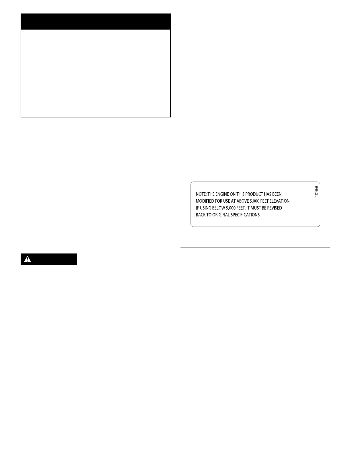
Ifyouareunsurewhetherornotyourmachinehas
beenconvertedforhigh-altitudeuse,lookforthe
followinglabel(Figure3).
Becauseinsomeareastherearelocal,state,or
federalregulationsrequiringthatasparkarresterbe
usedontheengineofthismachine,asparkarresteris
availableasanoption.Ifyourequireasparkarrester,
contactyourAuthorizedToroDealer.
GenuineT orosparkarrestersareapprovedbythe
USDAForestryService.
WARNING
Removingstandardoriginalequipmentparts
andaccessoriesmayalterthewarranty,
traction,andsafetyofthemachine.Failureto
useoriginalT oropartscouldcauseserious
injuryordeath.Makingunauthorizedchanges
totheengine,fuelorventingsystem,may
violateEPAandCARBregulations.
Replaceallpartsincluding,butnotlimited
to,tires,belts,blades,andfuelsystem
componentswithoriginalToroparts.
ForallmodelsthatdonothaveToroengines,
pleaserefertotheenginemanufacturer’s
informationincludedwiththemachine.
decal127-9363
Figure3
Labeledpowerratingsaresuppliedbytheengine
manufacturerinaccordancewithSAEtestingand
gross/netpowerratingstandards(J1940,J1995,
J1349).
Important:IfyouareusingamachinewithaToro
engineabove1500m(5,000ft)foracontinuous
©2017—TheToro®Company
8111LyndaleAvenueSouth
Bloomington,MN55420
Contactusatwww.Toro.com.
2
PrintedintheUSA
AllRightsReserved
Page 3
Introduction
Thisrotary-blade,ridinglawnmowerisintendedtobe
usedbyresidentialhomeownersorprofessional,hired
operators.Itisdesignedprimarilyforcuttinggrasson
well-maintainedlawnsonresidentialorcommercial
properties.Itisnotdesignedforcuttingbrushorfor
agriculturaluses.
Readthisinformationcarefullytolearnhowtooperate
andmaintainyourproductproperlyandtoavoid
injuryandproductdamage.Youareresponsiblefor
operatingtheproductproperlyandsafely .
YoumaycontactT orodirectlyatwww.T oro.com
forproductsafetyandoperationtrainingmaterials,
accessoryinformation,helpndingadealer,orto
registeryourproduct.
Wheneveryouneedservice,genuineToroparts,or
additionalinformation,contactanAuthorizedService
DealerorToroCustomerServiceandhavethemodel
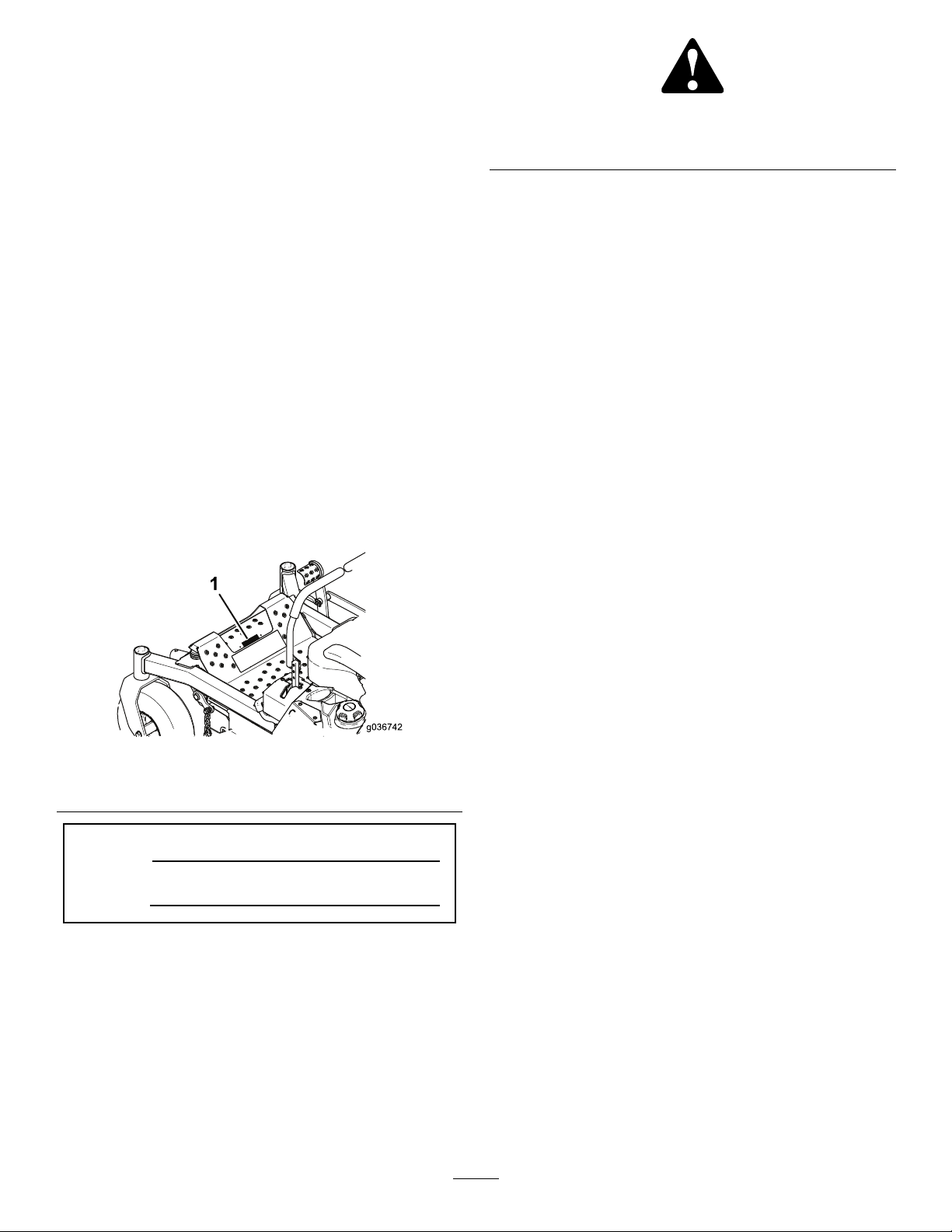
andserialnumbersofyourproductready.Figure1
identiesthelocationofthemodelandserialnumbers
ontheproduct.Writethenumbersinthespace
provided.
Figure1
1.Modelandserialnumberlocation
ModelNo.
SerialNo.
Thismanualidentiespotentialhazardsandhas
safetymessagesidentiedbythesafety-alertsymbol
(Figure2),whichsignalsahazardthatmaycause
seriousinjuryordeathifyoudonotfollowthe
recommendedprecautions.
g000502
Figure2
1.Safety-alertsymbol
Thismanualuses2wordstohighlightinformation.
Importantcallsattentiontospecialmechanical
informationandNoteemphasizesgeneralinformation
worthyofspecialattention.
Contents
Safety.......................................................................5
GeneralSafety...................................................5
SlopeIndicator...................................................6
SafetyandInstructionalDecals..........................7
ProductOverview...................................................14
Controls...........................................................14
Specications..................................................15
BeforeOperation.................................................16
BeforeOperationSafety...................................16
RecommendedFuel.........................................17
UsingStabilizer/Conditioner.............................17
FillingtheFuelTank..........................................17
CheckingtheEngine-OilLevel..........................17
UsingtheRollover-ProtectionSystem
(ROPS).........................................................18
ThinkSafetyFirst..............................................19
UsingtheSafety-InterlockSystem....................20
PositioningtheSeat..........................................20
ChangingtheSeatSuspension.........................20
BreakinginaNewMachine..............................21
g036742
UsingAttachmentsandAccessories.................21
DuringOperation.................................................21
DuringOperationSafety...................................21
OperatingtheParkingBrake.............................23
OperatingtheMowerBlade-ControlSwitch
(PTO)............................................................23
OperatingtheThrottle.......................................23
OperatingtheChoke.........................................24
OperatingtheIgnitionSwitch............................24
StartingtheEngine...........................................24
ShuttingOfftheEngine.....................................25
DrivingForwardorBackward............................26
AdjustingtheHeight-of-Cut...............................28
AdjustingtheAnti-ScalpRollers........................28
AdjustingtheSideBumpers..............................29
StoppingtheMachine.......................................29
UsingtheSideDischarge.................................30
OperatingTips.................................................30
AfterOperation....................................................31
AfterOperationSafety......................................31
UsingtheFuel-ShutoffValve.............................31
UsingtheDrive-Wheel-ReleaseValves............31
3
Page 4

TransportingtheMachine.................................32
LoadingtheMachine........................................33
Maintenance...........................................................35
RecommendedMaintenanceSchedule(s)...........35
Pre-MaintenanceProcedures..............................37
MaintenanceandStorage.................................37
Lubrication..........................................................38
GreasingtheMachine.......................................38
LubricatingtheCaster-WheelHubs..................39
EngineMaintenance...........................................40
EngineSafety...................................................40
ServicingaKawasaki
ServicingaKohler
®
Engine..........................41
®
Engine...............................46
ServicingaT oroEngine....................................50
CheckingtheSparkArrester.............................55
ReplacingtheEmissions-AirIntake
Filter..............................................................55
FuelSystemMaintenance...................................55
ReplacingtheFuelFilter...................................55
ServicingtheFuelT ank.....................................56
ElectricalSystemMaintenance...........................56
ElectricalSystemSafety...................................56
ServicingtheBattery.........................................56
ServicingtheFuses..........................................58
DriveSystemMaintenance..................................59
CheckingtheSeatBelt.....................................59
CheckingtheRollover-Protection-System
(ROPS)Knobs..............................................59
AdjustingtheTracking......................................60
CheckingtheTirePressure...............................60
CheckingtheWheelLugNuts...........................60
CoolingSystemMaintenance..............................61
CleaningtheEngineScreen.............................61
BrakeMaintenance.............................................61
AdjustingtheParkingBrake..............................61
BeltMaintenance................................................63
InspectingtheBelts..........................................63
ReplacingtheMowerBeltforSideDischarge
MowerDecks................................................63
ReplacingtheMowerBeltforRearDischarge
MowerDecks................................................64
ReplacingtheHydraulicPump-Drive
Belt................................................................66
ControlsSystemMaintenance.............................67
AdjustingtheControl-HandlePosition..............67
AdjustingtheMotion-ControlLinkage...............67
HydraulicSystemMaintenance...........................69
HydraulicSystemSafety...................................69
ServicingtheHydraulicSystem........................69
ChangingtheHydraulic-SystemFiltersand
Fluid..............................................................70
MowerDeckMaintenance....................................72
LevelingtheMowerDeck..................................72
ServicingtheCuttingBlades.............................74
RemovingtheMowerDeck...............................78
ReplacingtheGrassDeector..........................78
Cleaning..............................................................79
CleaningundertheMower................................79
DisposingofWaste...........................................79
Storage...................................................................80
CleaningandStorage.......................................80
Troubleshooting......................................................81
Schematics.............................................................83
4
Page 5

Safety
Thismachinehasbeendesignedinaccordancewith
ANSIB71.4-2012.
GeneralSafety
Thisproductiscapableofamputatinghandsand
feetandofthrowingobjects.Alwaysfollowallsafety
instructionstoavoidseriouspersonalinjury.
Usingthisproductforpurposesotherthanitsintended
usecouldprovedangeroustoyouandbystanders.
•Readandunderstandthecontentsofthis
Operator’sManualbeforeyoustarttheengine.
Ensurethateveryoneusingthisproductknows
howtouseitandunderstandsthewarnings.
•Donotputyourhandsorfeetnearmoving
componentsofthemachine.
•Donotoperatethemachinewithoutallguards
andothersafetyprotectivedevicesinplaceand
workingonthemachine.
•Keepclearofanydischargeopening.Keep
bystandersasafedistancefromthemachine.
•Keepchildrenoutoftheoperatingarea.Never
allowchildrentooperatethemachine.
•Stopthemachineandshutofftheenginebefore
servicing,fueling,oruncloggingthemachine.
Improperlyusingormaintainingthismachinecan
resultininjury.Toreducethepotentialforinjury,
complywiththesesafetyinstructionsandalwayspay
attentiontothesafety-alertsymbol,whichmeans
Caution,Warning,orDanger—personalsafety
instruction.Failuretocomplywiththeseinstructions
mayresultinpersonalinjuryordeath.
Youcanndadditionalitemsofsafetyinformationin
theirrespectivesectionsthroughoutthismanual.
5
Page 6
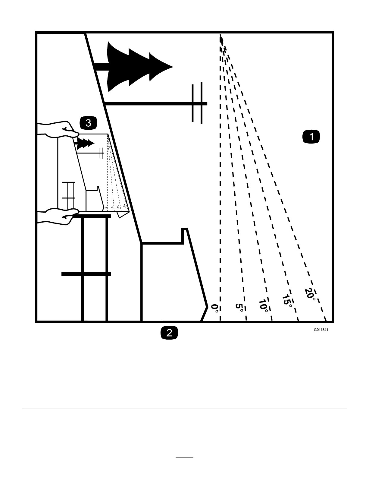
SlopeIndicator
Figure4
Thispagemaybecopiedforpersonaluse.
1.Themaximumslopeyoucansafelyoperatethemachineonis15degrees.Usetheslopecharttodeterminethedegreeofslope
ofhillsbeforeoperating.Donotoperatethismachineonaslopegreaterthan15degrees.Foldalongtheappropriateline
tomatchtherecommendedslope.
2.Alignthisedgewithaverticalsurface,atree,building,fencepole,etc.
3.Exampleofhowtocompareslopewithfoldededge
6
g011841
Page 7
SafetyandInstructionalDecals
Safetydecalsandinstructionsareeasilyvisibletotheoperatorandarelocatednearanyarea
ofpotentialdanger.Replaceanydecalthatisdamagedormissing.
Manufacturer'sMark
1.Indicatesthebladeisidentiedasapartfromtheoriginal
machinemanufacturer.
93-7818
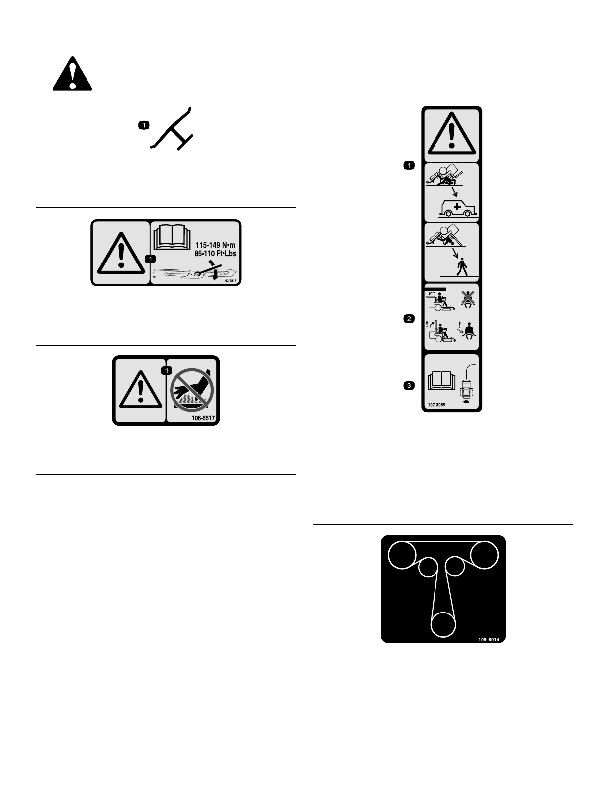
1.Warning—readtheOperator'sManualforinstructionson
torquingthebladebolt/nutto115-149N∙m(85-110ft-lb).
decaloemmarkt
decal93-7818
1.Warning—donottouchthehotsurface.
decal107-3069
decal106-5517
106-5517
1.Warning–thereisnorolloverprotectionwhentherollbaris
down.
2.Toavoidinjuryordeathfromarolloveraccident,keepthe
rollbarintheraisedandlockedpositionandweartheseat
belt.Lowertherollbaronlywhenabsolutelynecessary;do
notweartheseatbeltwhentherollbarisdown.
3.ReadtheOperator'sManual;driveslowlyandcarefully.
107-3069
decal109-6014
109-6014
7
Page 8
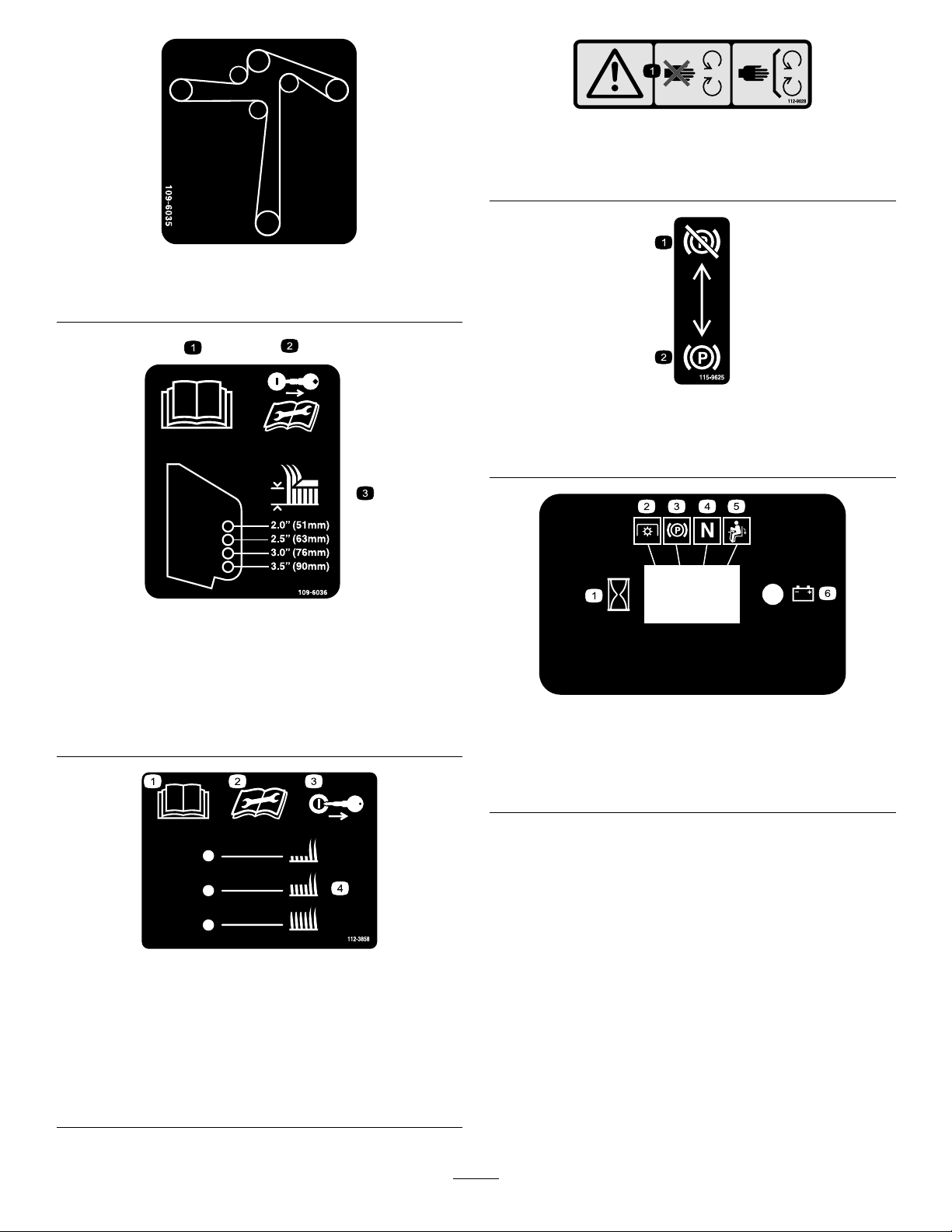
109-6035
2500SeriesSideDischargeMachinesOnly
decal112-9028
112-9028
1.Warning—stayawayfrommovingparts;keepallguardsin
place.
decal109-6035
decal115-9625
115-9625
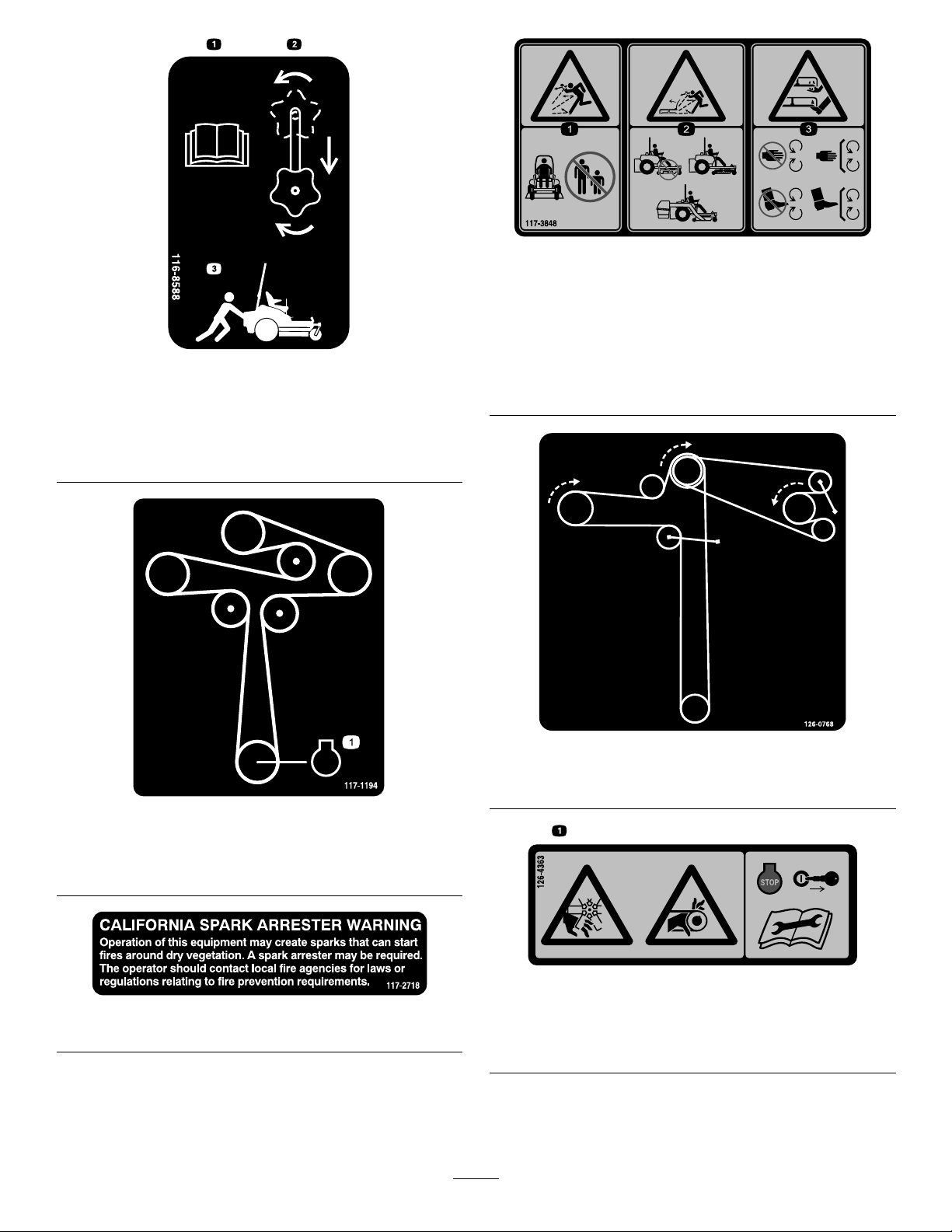
109-6036
RearDischargeMachinesOnly
1.ReadtheOperator’sManual.
2.Removetheignitionkeyandreadtheinstructionsbefore
servicingorperformingmaintenance.
3.Heightofcut
1.Parking
2.Parkingbrake—engaged
brake—disengaged
decal109-6036
decalhourmessagedisplay-116-5610
MessageDisplay
1.Hour4.Neutral
2.PTO5.Operator-presenceswitch
3.Parkingbrake6.Battery
112-3858
1500and2000SeriesSideDischargeMachinesOnly
1.ReadtheOperator's
Manual.
2.Readtheinstructions
beforeservicingor
performingmaintenance.
3.Removetheignitionkey
beforeadjustingtheheight
ofcut.
4.Height-of-cutsettings.
decal112-3858
8
Page 9
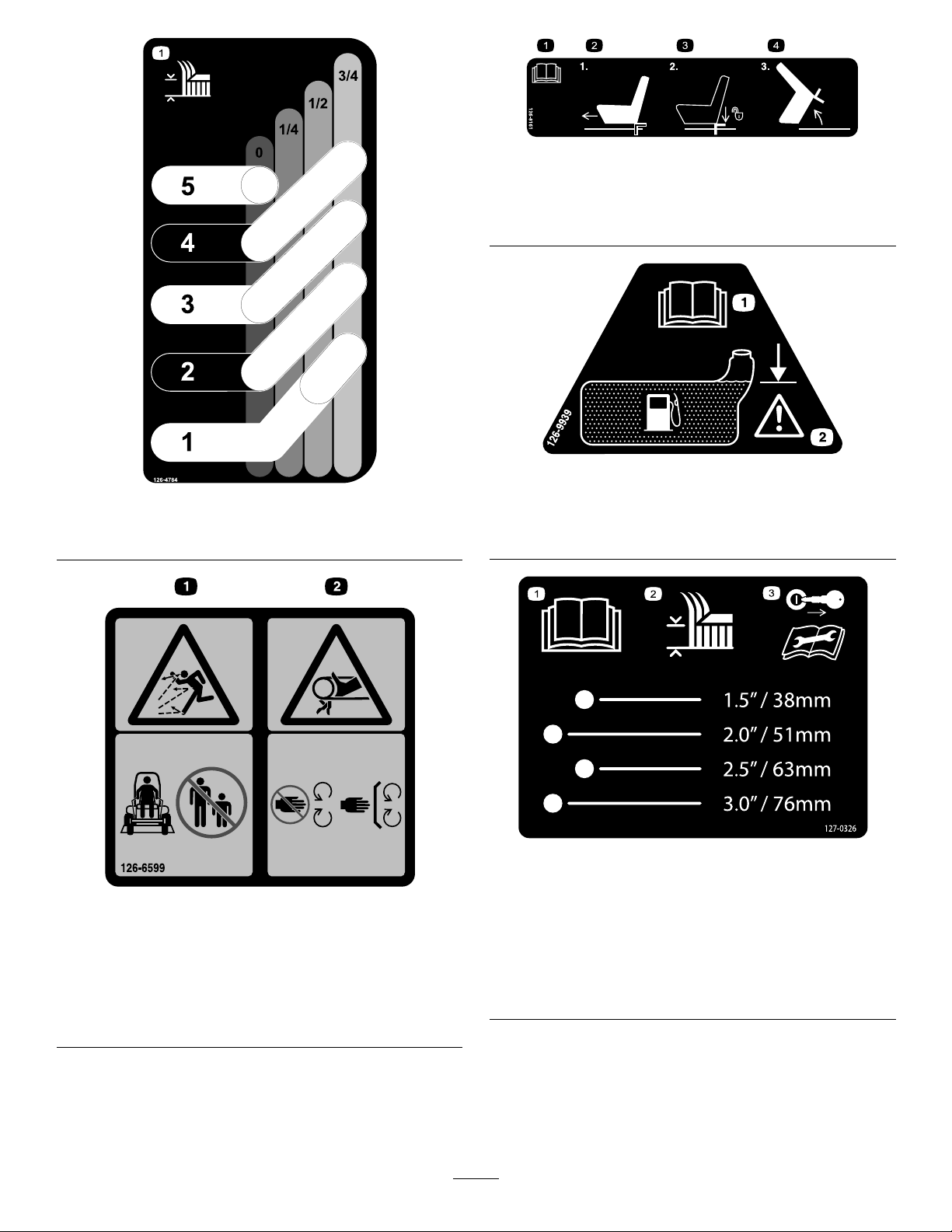
116-8588
1.ReadtheOperator’sManual.
2.Rotatethedrivereleaseknobtoloosen,slidetheknob,
andtighten.
3.Pushthemachine.
decal117-3848
117-3848
1.Thrownobjecthazard—keepbystandersasafedistance
fromthemachine.
2.Thrownobjecthazard,mower—donotoperatethemachine
withoutdeector,dischargecover,orgrasscollection
decal116-8588
systeminplace.
3.Cutting/dismembermentofhandorfoot—stayawayfrom
movingparts;keepallguardsandshieldsinplace.
117-1194
1500and2000SeriesSide-DischargeMachinesOnly
1.Engine
117-2718
decal126-0768
126-0768
RearDischargeUnitsOnly
decal117-1 194
decal126-4363
126-4363
decal117-2718
1.Cutting/dismembermenthazard,fanandentanglement
hazard,belt.Shutofftheengineandremovekeybefore
adjusting,servicingorcleaning.
9
Page 10
decal126-8161
126-8161
1.Heightofcut
1.ReadtheOperator’s
Manual.
2.Slideseatforward
decal126-4784
126-4784
1.ReadtheOperator’s
Manual
3.Pressdownonlatchto
unlockseat
4.Rotateseat
decal126-9939
126-9939
2.Filltobottomofllerneck;
warning–donotoverllthe
tank
1.Thrownobjectshazard
-keepbystandersa
safedistancefromthe
machine.
126-6599
RearDischargeUnits
2.Cutting/dismemberment
ofhand-stayawayfrom
movingparts;keepall
guardsandshieldsin
place.
decal127-0326
127-0326
decal126-6599
2500SeriesSideDischargeMachinesOnly
1.ReadtheOperator's
Manual.
2.Heightofcut
3.Removethekeyfrom
theignitionandreadthe
Operator'sManualbefore
performingmaintenance
orservicingthemachine.
10
Page 11
127-6662
RearDischargeMowersOnly
decal131-1097
131-1097
ToroEnginesOnly
decal127-6662
1.Oildrain
1.Attention—readthe
Operator'sManual.
2.Removethenutbyturning
itclockwise.
3.Removetheboltbyturning
itcounterclockwise.
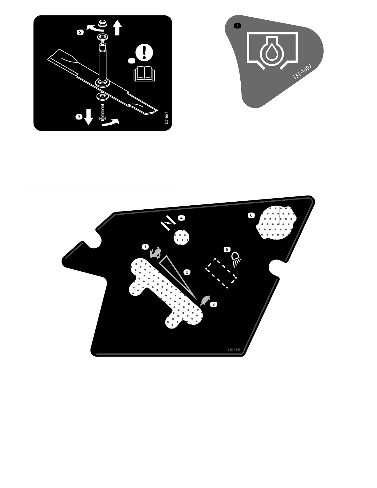
136-1305
1.Fast
2.Continuousvariablesetting5.Worklight(optional)
3.Slow
4.Choke
6.Powerpoint
11
decal136-1305
Page 12
PTOSwitchSymbols
1.PTO–disengage2.PTO–engage
decalptosymbols
decalmotioncntrlrh-126-6183
RightMotionControl
TransportLock
1.Heightofcut
LeftMotionControl
1.Machinespeed4.Neutral
2.Fast5.Reverse
3.Slow
2.Pulluptounlockthe
transportlock
decalmotioncntrllh-126-6194
decaltransportlock
1.Machinespeed4.Neutral
2.Fast5.Reverse
3.Slow
decalbatterysymbols
BatterySymbols
Someorallofthesesymbolsareonyourbattery .
1.Explosionhazard
2.Nore,opename,or
smoking
3.Causticliquid/chemical
burnhazard
4.Weareyeprotection.9.Flusheyesimmediately
5.ReadtheOperator's
Manual.
6.Keepbystandersasafe
distancefromthebattery.
7.Weareyeprotection;
explosivegasescan
causeblindnessandother
injuries.
8.Batteryacidcancause
blindnessorsevereburns.
withwaterandgetmedical
helpfast.
10.Containslead;donot
discard
12
Page 13
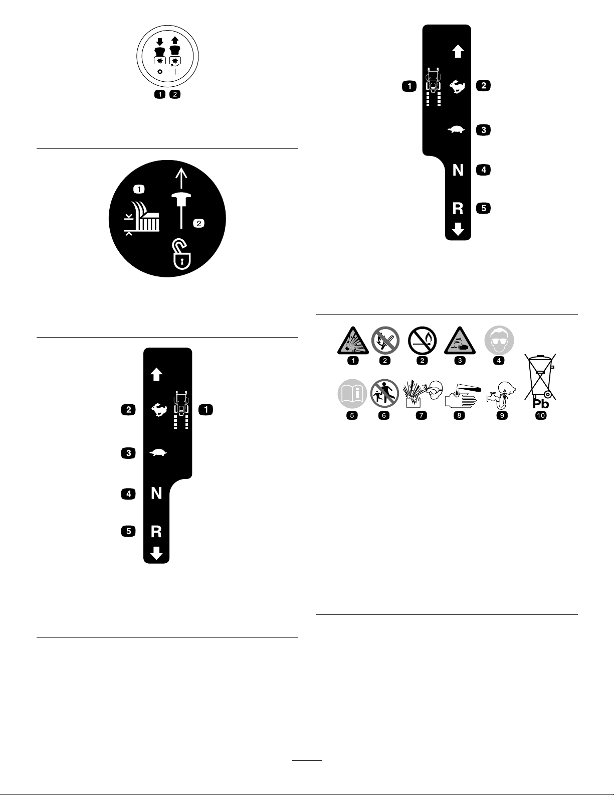
decal126-8151
126-8151
1.Readtheinstructionsbeforeservicingorperforming
4.RefertotheOperator'sManualforgreaseinstructions
maintenance
2.Timeinterval
5.Checkthehydraulic-uidlevelandrefertotheOperator's
Manualorfurtherinstructions
3.Checkoillevel6.Checktirepressure
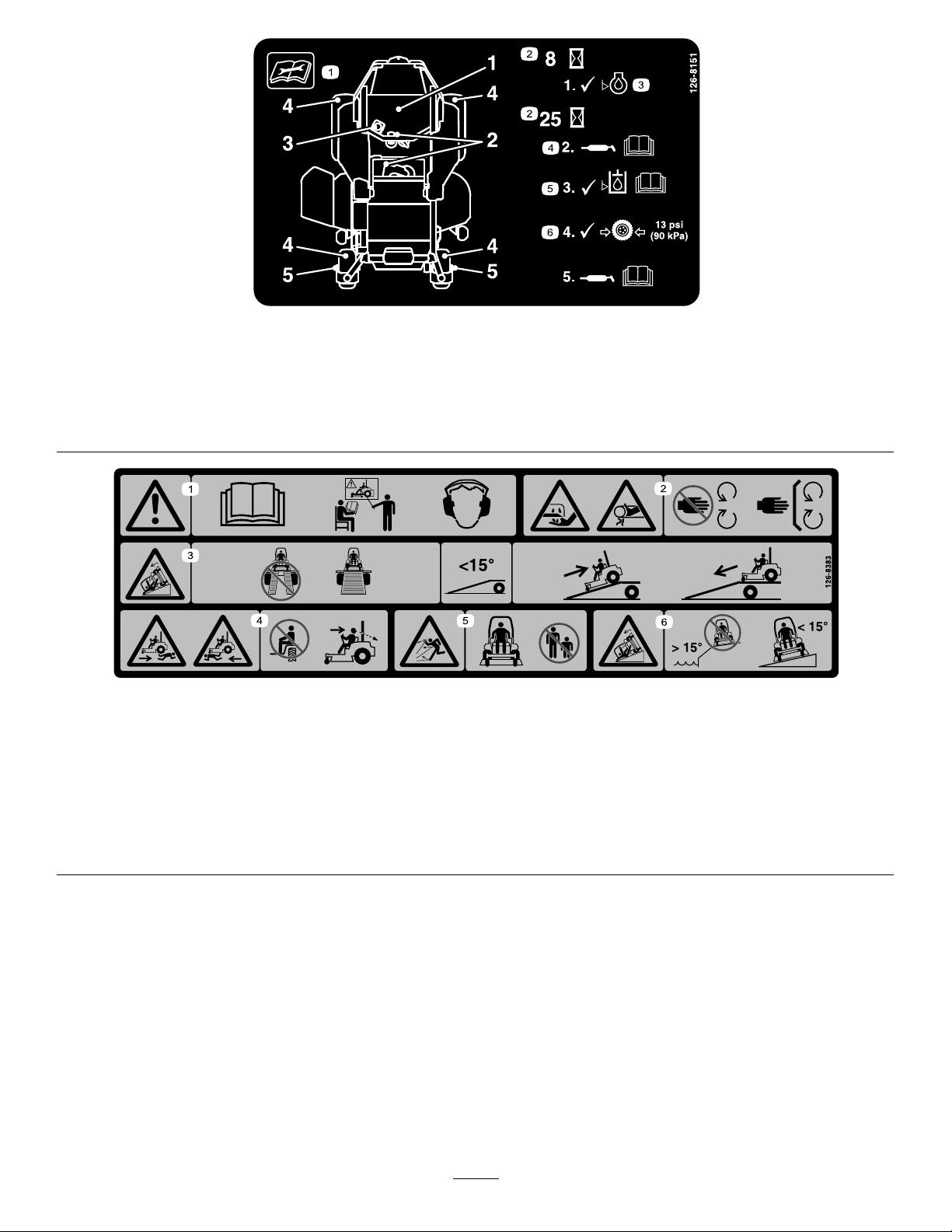
126-8383
1.Warning-ReadtheOperator'sManual.Donotoperatethis
machineunlessyouaretrained.Wearhearingprotection.
2.Cuttingandpinchinghazard-keephandsandfeetawayfrom
movingparts;keepallguardsandshieldsinplace.
3.Ramphazard-whenloadingontoatrailer,donotusedual
ramps;onlyuseasingularrampwideenoughforthemachine
andthathasaninclinelessthan15degrees;backupthe
ramp(inreverse)anddriveforwardofftheramp.
4.Bodilyharmhazard-lookbehindyouwhenmowingin
reverse.
5.Thrownobjecthazard-keepbystandersaway .
6.Tippinghazardonslopes-donotuseonslopesnearopen
water;donotuseonslopesgreaterthan15degrees.
decal126-8383
13
Page 14
ProductOverview
HourMeter
Thehourmeterrecordsthenumberofhoursthe
enginehasoperated.Itoperateswhentheengine
isrunning.Usethesetimesforschedulingregular
maintenance(Figure6).
ThrottleControl
ThethrottlecontrolisvariablebetweenFastand
Slow.
Choke
Usethechoketostartacoldengine.Pullthechoke
knobuptoengageit.
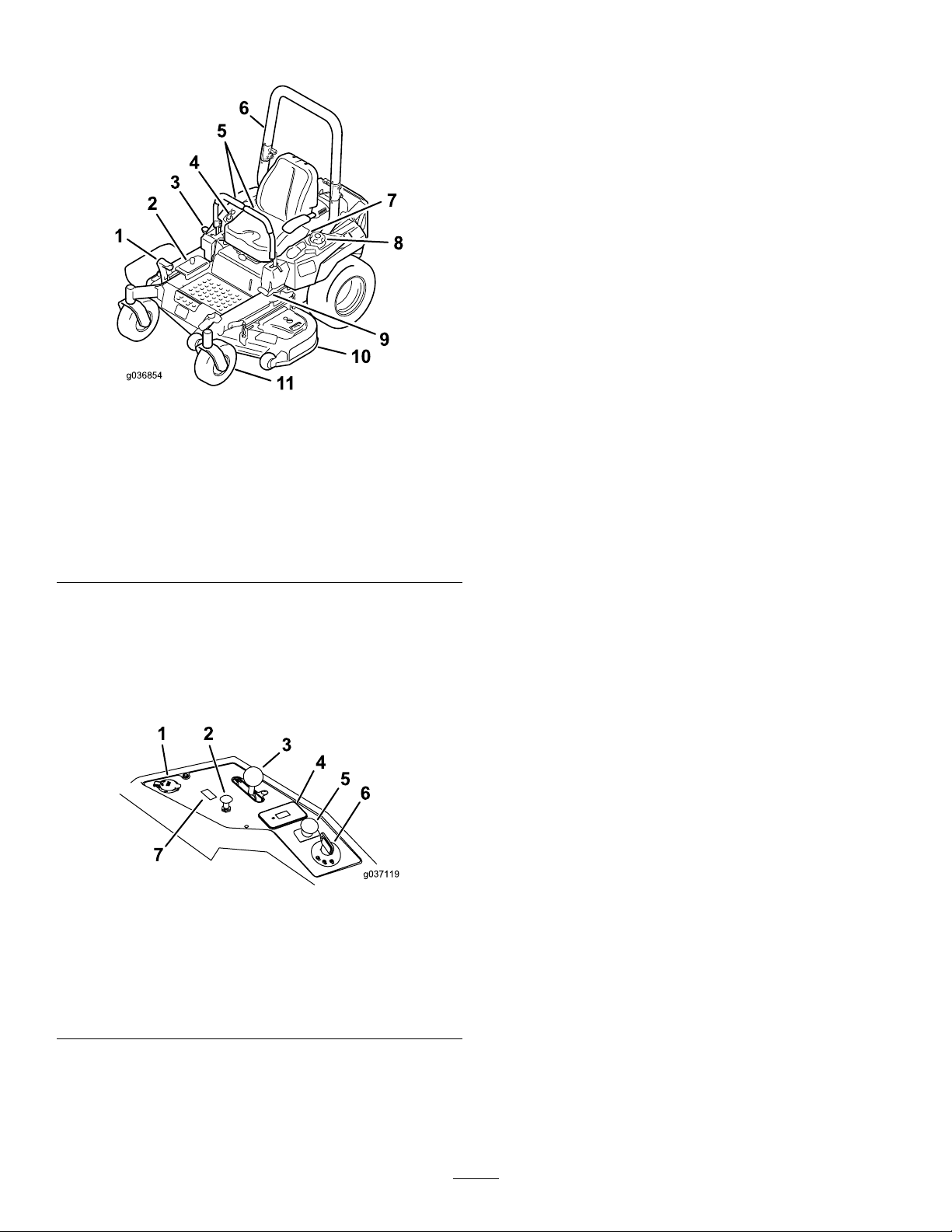
Figure5
1.Height-of-cutdeck-lift
pedal
2.Height-of-cutpositions
3.Transportlock9.Parking-brakelever
4.Controls
5.Motion-controllevers
6.Rollbar
7.Seatbelt
8.Fuelcap
10.Mowerdeck
11.Casterwheel
Controls
Becomefamiliarwithallthecontrolsbeforeyoustart
theengineandoperatethemachine(Figure5and
Figure6).
g036854
Blade-ControlSwitch(PTO)
Usetheblade-controlswitch(PTO)toengagethe
electricclutchanddrivethemowerblades.Pullthe
switchuptoengagethebladesandrelease.T o
disengagetheblades,pushtheblade-controlswitch
(PTO)downormoveamotion-controlleverintothe
NEUTRAL-LOCKposition.
IgnitionSwitch
Thisswitchisusedtostartthemowerengineandhas
3positions:START,RUN,andOFF.
Motion-ControlLevers
Themotion-controlleversareusedtodrivethe
machineforward,reverse,andturneitherdirection.
Neutral-LockPosition
UsetheNEUTRAL-LOCKpositionwiththe
safety-interlocksystemtoengageandtodetermine
theNEUTRALposition.
1.Powerpoint
2.Choke
3.Throttlecontrol
4.Hourmeter
Figure6
5.PTOSwitch
6.Ignitionswitch
7.Switchpositionforoptional
lightkit
g037119
Fuel-ShutoffValve
Closethefuel-shutoffvalve(undertheseat)when
transportingorstoringthemower.
Attachments/Accessories
AselectionofToroapprovedattachmentsand
accessoriesisavailableforusewiththemachineto
enhanceandexpanditscapabilities.Contactyour
AuthorizedServiceDealerorDistributororgoto
www.T oro.comforalistofallapprovedattachments
andaccessories.
14
Page 15

Specications
Note:Specicationsanddesignaresubjecttochangewithoutnotice.
Width—MachineswithSideDischargeMowerDecks
48-inchDeck52-inchDeck60-inchDeck
Withoutmowerdeck
Deectorup133cm(53inches)144cm(56-3/4inches)161cm(63-1/2inches)
Deectordown160cm(63-1/4inches)171cm(67-1/4inches)191cm(75-1/4inches)
Width—MachineswithRearDischargeMowerDecks
Withoutmowerdeck
Withmowerdeck
Length—MachineswithSideDischargeMowerDecks
Length
Length—MachineswithRearDischargeMowerDecks
121cm(47-1/2inches)124cm(49inches)133cm(52inches)
60-inchDeck
133cm(52inches)
168cm(66inches)
48-inchDeck52-inchDeck60-inchDeck
208cm(82inches)208cm(82inches)209cm(83inches)
60-inchDeck
Withmowerdeck
215cm(84-1/2inches)
Height
RollBar-UpRollBar-Down
179cm(70-1/2inches)49inches(125cm)
Weight
MachinesWeight
48-inchside-dischargemachines
52-inchside-dischargemachines
60-inchside-dischargemachines
60-inchrear-dischargemachines
385to425kg(849to937lb)
391to434kg(862to957lb)
409to456kg(901to1006lb)
459kg(1012lb)
15
Page 16

Operation
Note:Determinetheleftandrightsidesofthe
machinefromthenormaloperatingposition.
BeforeOperation
BeforeOperationSafety
•Donotllcontainersinsideavehicleoronatruck
ortrailerbedwithaplasticliner.Alwaysplace
containersontheground,awayfromyourvehicle
beforelling.
•Removetheequipmentfromthetruckortrailer
andrefuelitwhileitisontheground.Ifthisisnot
possible,thenrefuelfromaportablecontainer
ratherthanafuel-dispensernozzle.
•Donotoperatethemachinewithouttheentire
exhaustsysteminplaceandinproperworking
condition.
GeneralSafety
•Neverallowchildrenoruntrainedpeopleto
operateorservicethemachine.Localregulations
mayrestricttheageoftheoperator.Theowner
isresponsiblefortrainingalloperatorsand
mechanics.
•Becomefamiliarwiththesafeoperationofthe
equipment,operatorcontrols,andsafetysigns.
•Knowhowtostopthemachineandenginequickly.
•Checkthatoperator-presencecontrols,safety
switches,andshieldsareattachedandfunctioning
properly.Donotoperatethemachineunlessthey
arefunctioningproperly.
•Beforemowing,alwaysinspectthemachineto
ensurethattheblades,bladebolts,andcutting
assembliesareingoodworkingcondition.
Replacewornordamagedbladesandboltsinsets
topreservebalance.
•Inspecttheareawhereyouwillusethemachine
andremoveallobjectsthatthemachinecould
throw.
•Evaluatetheterraintodeterminetheappropriate
equipmentandanyattachmentsoraccessories
requiredtooperatethemachineproperlyand
safely.
•Keepthefuel-dispensernozzleincontactwith
therimofthefueltankorcontaineropeningat
alltimesuntilfuelingiscomplete.Donotusea
nozzlelock-opendevice.
•Ifyouspillfuelonyourclothing,changeyour
clothingimmediately.Wipeupanygasolinethat
spills.
•Neveroverllthefueltank.Replacethefuelcap
andtightenitsecurely.
•Storegasolineinanapprovedcontainerandkeep
itoutofthereachofchildren.Neverbuymore
thana30-daysupplyofgasoline.
•Donotllthefueltankcompletelyfull.Add
gasolinetothefueltankuntilthelevelis6to13
mm(1/4to1/2inch)belowthebottomoftheller
neck.Thisemptyspaceinthetankallowsgasoline
toexpand.
–Avoidprolongedbreathingofvapors.
–Keepyourfaceawayfromthenozzleandgas
tankopening.
–Avoidcontactwithskin;washoffspillswith
soapandwater.
FuelSafety
•Toavoidpersonalinjuryorpropertydamage,use
extremecareinhandlingfuel.Fuelvaporsare
ammableandexplosive.
•Extinguishallcigarettes,cigars,pipes,andother
sourcesofignition.
•Useonlyanapprovedfuelcontainer.
•Donotremovethefuelcaporaddfueltothefuel
tankwhiletheengineisrunningorwhilehot.
•Donotrefuelthemachineindoors.
•Donotstorethemachineorfuelcontainerwhere
thereisanopename,spark,orpilotlight,such
asonawaterheateroronotherappliances.
16
Page 17
RecommendedFuel
•Forbestresults,useonlyclean,fresh(lessthan
30daysold),unleadedgasolinewithanoctane
ratingof87orhigher((R+M)/2ratingmethod).
•Ethanol:Gasolinewithupto10%ethanol
(gasohol)or15%MTBE(methyltertiarybutyl
ether)byvolumeisacceptable.Ethanoland
MTBEarenotthesame.Gasolinewith15%
ethanol(E15)byvolumeisnotapprovedforuse.
Neverusegasolinethatcontainsmorethan
10%ethanolbyvolume,suchasE15(contains
15%ethanol),E20(contains20%ethanol),orE85
(containsupto85%ethanol).Usingunapproved
gasolinemaycauseperformanceproblemsand/or
enginedamagewhichmaynotbecoveredunder
warranty.
•Donotusegasolinecontainingmethanol.
•Donotstorefueleitherinthefueltankorfuel
containersoverthewinterunlessafuelstabilizer
isused.
•Donotaddoiltogasoline.
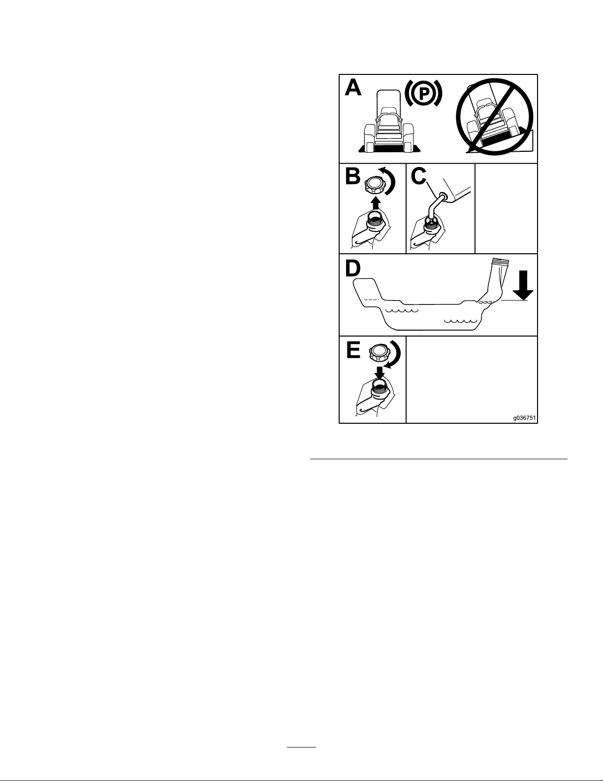
4.Fillthefueltanktothebottomofthellerneck.
5.Ensurethatthereisemptyspaceinthetankto
allowthegasolinetoexpand(Figure7).
Using Stabilizer/Conditioner
Useafuelstabilizer/conditionerinthemachineto
providethefollowingbenets:
•Keepsgasolinefreshduringstorageof90daysor
less.Forlongerstorageitisrecommendedthat
thefueltankbedrained.
•Cleanstheenginewhileitruns
•Eliminatesgum-likevarnishbuildupinthefuel
system,whichcauseshardstarting
Important:Donotusefueladditives
containingmethanolorethanol.
Addthecorrectamountofgasoline
stabilizer/conditionertothegasoline.
Note:Afuelstabilizer/conditionerismosteffective
whenmixedwithfreshgasoline.T ominimizethe
chanceofvarnishdepositsinthefuelsystem,use
fuelstabilizeratalltimes.
Figure7
CheckingtheEngine-Oil Level
Beforeyoustarttheengineandusethemachine,
checktheoillevelintheenginecrankcase.For
KawasakienginesrefertoServicingaKawasaki
Engine(page41),forKohlerenginesrefertoServicing
aKohler
refertoServicingaT oroEngine(page50).
®
Engine(page46),andforT oroengines
g036751
®
FillingtheFuelTank
Note:Donotllthefueltankcompletelyfull.Fillthe
fueltanktothebottomofthellerneck.Theempty
spaceinthetankallowsthegasolinetoexpand.
1.Parkthemachineonlevelground.
2.Shuttheengineoffandsettheparkingbrake.
3.Cleanaroundthefuel-tankcap.
17
Page 18
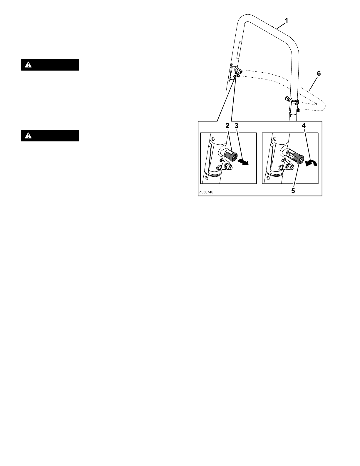
Usingthe Rollover-ProtectionSystem (ROPS)
WARNING
Toavoidinjuryordeathfromrollover:keep
therollbarinthefullyraised,lockedposition
andusetheseatbelt.
Ensurethattheseatissecuredtothe
machine.
WARNING
Thereisnorolloverprotectionwhentheroll
barisinthedownposition.
•Lowertherollbaronlywhenabsolutely
necessary.
•Donotweartheseatbeltwhentherollbar
isinthedownposition.
•Driveslowlyandcarefully.
g036746
Figure8
•Raisetherollbarassoonasclearance
permits.
•Checkcarefullyforoverheadclearances
(i.e.,branches,doorways,electricalwires)
beforedrivingunderanyobjects,anddo
notcontactthem.
Important:Ensurethattheseatissecuredto
themachine.
1.T olowertherollbar,applyforwardpressureto
theupperpartoftherollbar.
2.Pullbothknobsoutandrotatethem90degrees
sotheyarenotengaged(Figure8).
3.Lowertherollbartothedownposition(Figure
8).
1.Rollbarintheupright
position
2.ROPSknobinthelatched
position
3.PulltheROPSknobout.6.Rollbarinthefolded
4.T oraisetherollbar,raisetherollbartothe
operatingpositionandrotatetheknobsuntil
theymovepartiallyintothegrooves(Figure8).
5.Raisetherollbartothefulluprightpositionwhile
pushingontheupperrollbarsothatthepins
snapintopositionwhentheholesalignwiththe
pins(Figure8).
6.Pushontherollbarandensurethatbothpins
areengaged.
4.RotatetheROPSknob90
degrees.
5.ROPSknobinthe
unlatchedposition
position
Important:Alwaysusetheseatbeltwiththeroll
barintheraisedposition.
18
Page 19
ThinkSafetyFirst
Pleasereadallsafetyinstructionsandsymbolsinthe
safetysection.Knowingthisinformationcouldhelp
youorbystandersavoidinjury.
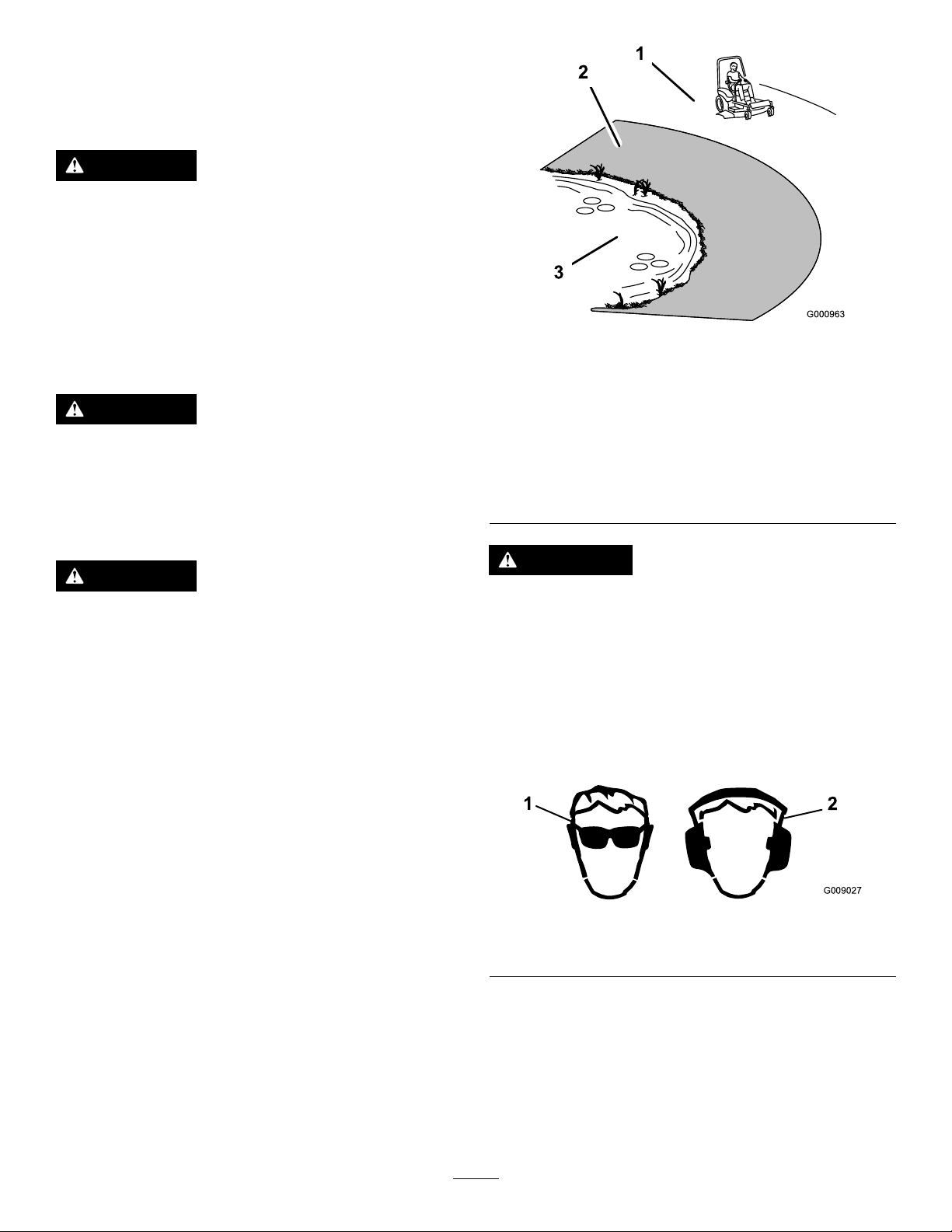
DANGER
Operatingthemachineonwetgrassorsteep
slopescancauseslidingandlossofcontrol.
•Donotoperateonslopesgreaterthan15
degrees.
•Reducespeedanduseextremecautionon
slopes.
•Donotoperatethemachinenearwater.
DANGER
Wheelsdroppingoveredgescancause
rollovers,whichmayresultinseriousinjury,
death,ordrowning.
Donotoperatethemachineneardrop-offs.
1.SafeZone—usethe
machinehereonslopes
lessthan15degreesor
atareas.
2.DangerZone—usea
walk-behindmowerand/or
ahandtrimmeronslopes
greaterthan15degrees,
neardrop-offsandwater.
g000963
Figure9
3.Water
DANGER
Operatingthemachinewhiletherollbaris
downmayleadtoseriousinjuryordeathin
theeventofarollover.
Alwayskeeptherollbarinthefullyraisedand
lockedpositionandusetheseatbelt.
CAUTION
Thismachineproducessoundlevelsin
excessof85dBAattheoperator’searand
cancausehearinglossthroughextended
periodsofexposure.
Wearhearingprotectionwhenoperatingthis
machine.
Theuseofprotectiveequipmentforeyes,ears,
hands,feet,andheadisrecommended.
g009027
Figure10
1.Weareyeprotection.2.Wearhearingprotection
19
Page 20
UsingtheSafety-Interlock System
Whiletheengineisrunning,releasetheparking
brake,engagetheblade-controlswitch(PTO),
andriseslightlyfromtheseat;theengineshould
shutoff.
CAUTION
Ifthesafety-interlockswitchesare
disconnectedordamaged,themachinecould
operateunexpectedly,causingpersonal
injury.
•Donottamperwiththeinterlockswitches.
•Checktheoperationoftheinterlock
switchesdailyandreplaceanydamaged
switchesbeforeoperatingthemachine.
Understandingthe
Safety-InterlockSystem
Thesafety-interlocksystemisdesignedtopreventthe
enginefromstartingunless:
•Theparkingbrakeisengaged.
•Theblade-controlswitch(PTO)isdisengaged.
•Themotion-controlleversareintheNEUTRAL-LOCK
position.
4.Sitontheseat,engagetheparkingbrake,
movetheblade-controlswitch(PTO)totheOFF
position,andmovethemotion-controllevers
toNEUTRAL-LOCKposition.Starttheengine.
Whiletheengineisrunning,centereither
motion-controlleverandmoveitforwardor
reverse;theengineshouldshutoff.Repeatfor
othermotion-controllever.
5.Sitontheseat,disengagetheparkingbrake,
movetheblade-controlswitch(PTO)totheOFF
position,andmovethemotion-controlleversto
NEUTRAL-LOCKposition.Trystartingtheengine;
theengineshouldnotcrank.
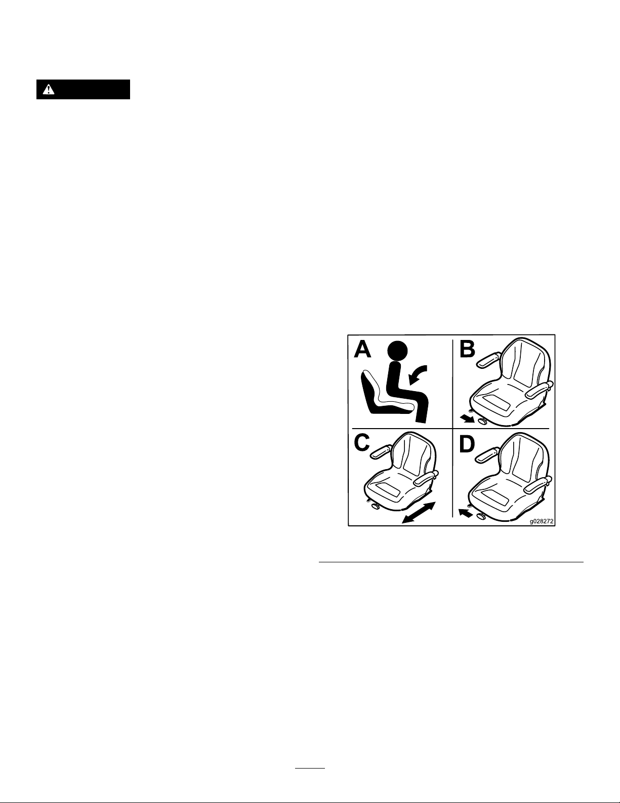
PositioningtheSeat
Theseatcanmoveforwardandbackward(Figure11).
Positiontheseatwhereyouhavethebestcontrolof
themachineandaremostcomfortable.
Thesafety-interlocksystemalsoisdesignedtoshutoff
theenginewhenyoumovethetractioncontrolsfrom
thelockedpositionwiththeparkingbrakeengagedor
ifyourisefromtheseatwhenthePTOisengaged.
TestingtheSafety-Interlock
System
ServiceInterval:Beforeeachuseordaily
Testthesafety-interlocksystembeforeyouusethe
machineeachtime.Ifthesafetysystemdoesnot
operateasdescribedbelow,haveanAuthorized
ServiceDealerrepairthesafetysystemimmediately .
1.Sitontheseat,engagetheparkingbrakeand
movetheblade-controlswitch(PTO)totheON
position.Trystartingtheengine;theengine
shouldnotcrank.
2.Sitontheseat,engagetheparkingbrakeand
movetheblade-controlswitch(PTO)totheOFF
position.Moveeithermotion-controllever(out
oftheNEUTRAL-LOCKposition).Trystartingthe
engine;theengineshouldnotcrank.Repeatfor
othercontrollever.
3.Sitontheseat,engagetheparkingbrake,
movetheblade-controlswitch(PTO)totheOFF
position,andmovethemotion-controlleversto
theNEUTRAL-LOCKposition.Starttheengine.
g028272
Figure11
ChangingtheSeat Suspension
Theseatisadjustabletoprovideasmoothand
comfortableride.Positiontheseatwhereyouare
mostcomfortable.
Toadjustit,turntheknobinfronteitherdirectionto
providethebestcomfort(Figure12).
20
Page 21
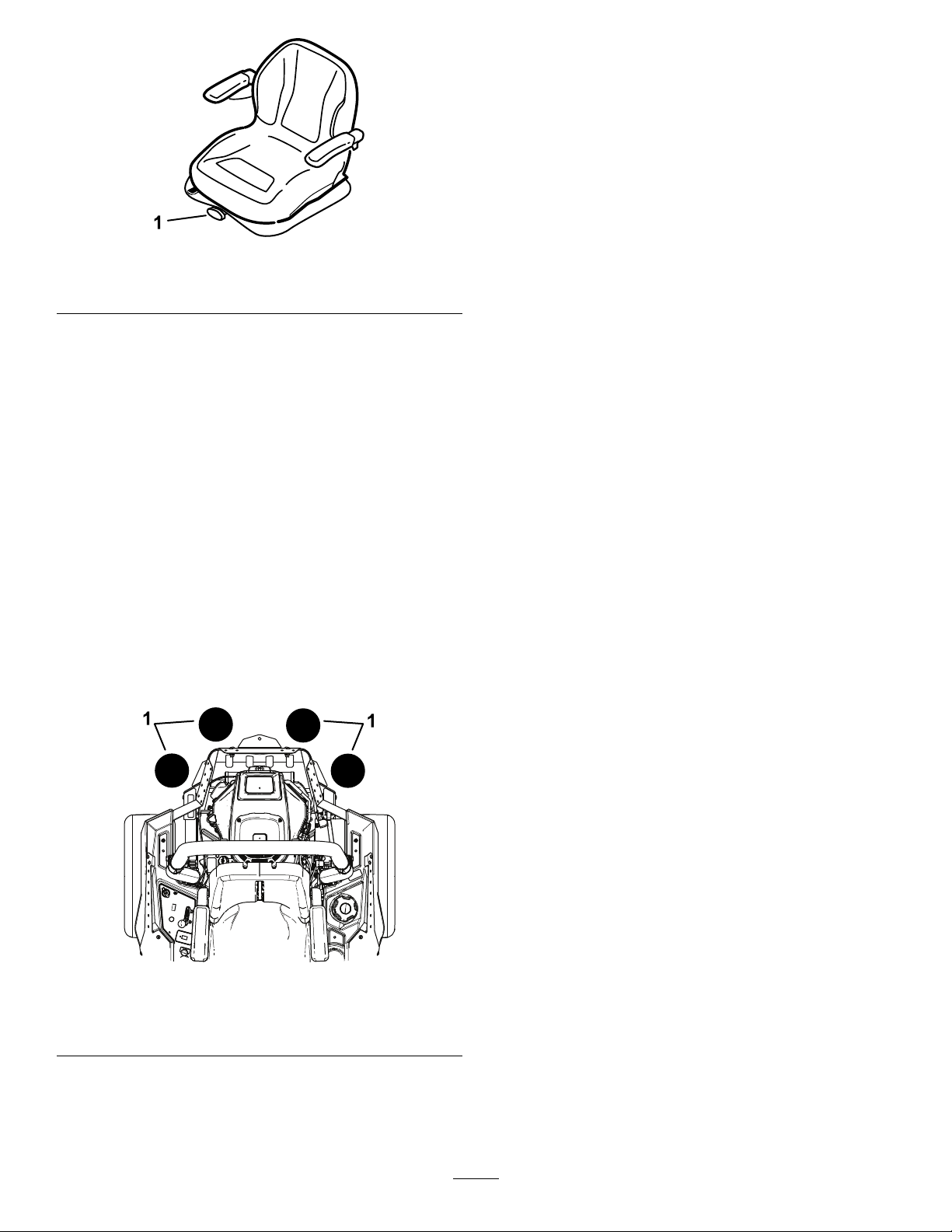
Figure12
1.Seat-suspensionknob
BreakinginaNewMachine
Newenginestaketimetodevelopfullpower.Mower
decksanddrivesystemshavehigherfrictionwhen
new,placingadditionalloadontheengine.Allow
40to50hoursofbreak-intimefornewmachinesto
developfullpowerandbestperformance.
UsingAttachmentsand Accessories
UseonlyToroapprovedattachmentsandaccessories.
Ifmorethanoneaccessory-mountkit(i.e.bucketkitor
universalmountkit)isaddedtoanyofthe4locations
showninFigure13,addafront-weightkit.Contact
yourauthorizedservicedealerforthefront-weightkit.
Figure13
1.Addafront-weightkitwhen2ormoreaccessory-mountkits
areinstalledatthesepositions.
DuringOperation
DuringOperationSafety
GeneralSafety
•Theowner/operatorcanpreventandisresponsible
foraccidentsthatmaycausepersonalinjuryor
propertydamage.
g024881
g037417
•Wearappropriateclothing,includingeye
protection;slip-resistant,substantialfootwear;and
hearingprotection.Tiebacklonghairanddonot
wearjewelry.
•Donotoperatethemachinewhileill,tired,or
undertheinuenceofalcoholordrugs.
•Nevercarrypassengersonthemachineandkeep
bystandersandpetsawayfromthemachine
duringoperation.
•Operatethemachineonlyingoodvisibilitytoavoid
holesorhiddenhazards.
•Avoidmowingonwetgrass.Reducedtraction
couldcausethemachinetoslide.
•Ensurethatalldrivesareinneutral,theparking
brakeisengaged,andyouareintheoperating
positionbeforeyoustarttheengine.
•Keepyourhandsandfeetawayfromthecutting
units.Keepclearofthedischargeopeningatall
times.
•Lookbehindanddownbeforebackinguptobe
sureofaclearpath.
•Usecarewhenapproachingblindcorners,shrubs,
trees,orotherobjectsthatmayobscureyour
vision.
•Donotmowneardrop-offs,ditches,or
embankments.Themachinecouldsuddenlyroll
overifawheelgoesovertheedgeoriftheedge
givesway.
•Stopthebladeswheneveryouarenotmowing.
•Stopthemachineandinspectthebladesafter
strikinganobjectorifthereisanabnormal
vibrationinthemachine.Makeallnecessary
repairsbeforeresumingoperation.
•Slowdownandusecautionwhenmakingturns
andcrossingroadsandsidewalkswiththe
machine.Alwaysyieldtheright-of-way.
•Disengagethedrivetothecuttingunitandshut
offtheenginebeforeadjustingtheheightof
cut(unlessyoucanadjustitfromtheoperating
position).
•Neverrunanengineinanareawhereexhaust
gasesareenclosed.
•Neverleavearunningmachineunattended.
21
Page 22

•Beforeleavingtheoperatingposition(including
toemptythecatchersortounclogthechute),do
thefollowing:
–Stopthemachineonlevelground.
–Disengagethepowertake-offandlowerthe
attachments.
–Settheparkingbrake.
–Shutofftheengineandremovethekey.
–Waitforallmovingpartstostop.
•Donotoperatethemachinewhenthereistherisk
oflightning.
•Donotusethemachineasatowingvehicle.
•Donotchangethegovernorspeedoroverspeed
theengine.
•Useaccessoriesandattachmentsapprovedby
Toroonly.
RolloverProtectionSystem
(ROPS)Safety
•DonotremovetheROPSfromthemachine.
•Ensurethattheseatbeltisattachedandthatyou
canreleaseitquicklyinanemergency.
•AlwayswearyourseatbeltwhentheROPSisup.
•Checkcarefullyforoverheadobstructionsanddo
notcontactthem.
•KeeptheROPSinsafeoperatingconditionby
thoroughlyinspectingitperiodicallyfordamage
andkeepingallthemountingfastenerstight.
•ReplaceadamagedROPS.Donotrepairoralter
it.
•Choosealowgroundspeedsoyouwillnothave
tostoporshiftwhileonaslope.
•Arollovercanoccurbeforethetireslosetraction.
•Avoidoperatingthemachineonwetgrass.Tires
maylosetraction;regardlessifthebrakesare
availableandfunctioning.
•Avoidstarting,stopping,orturningthemachine
onaslope.
•Keepallmovementonslopesslowandgradual.
Donotsuddenlychangethespeedordirectionof
themachine.
•Donotoperatethemachineneardrop-offs,
ditches,embankments,orbodiesofwater.The
machinecouldsuddenlyrolloverifawheelgoes
overtheedgeortheedgecavesin.Establisha
safetyareabetweenthemachineandanyhazard
(2machinewidths).
SlopeSafety
•Establishyourownproceduresandrulesfor
operatingonslopes.Theseproceduresmust
includesurveyingthesitetodeterminewhich
slopesaresafeformachineoperation.Always
usecommonsenseandgoodjudgmentwhen
performingthissurvey.
•Slopesareamajorfactorrelatedtoloss-of-control
andtip-overaccidents,whichcanresultinsevere
injuryordeath.Operatingthemachineonany
sloperequiresextracaution.
•Operatethemachineatalowerspeedwhenyou
areonaslope.
•Ifyoufeeluneasyoperatingthemachineona
slope,donotdoit.
•Watchforholes,ruts,bumps,rocks,orother
hiddenobjects.Uneventerraincouldoverturnthe
machine.T allgrasscanhideobstacles.
22
Page 23
OperatingtheParking Brake
Alwayssettheparkingbrakewhenyoustopthe
machineorleaveitunattended.
SettingtheParkingBrake
WARNING
Theparkingbrakemaynotholdamachine
parkedonaslopeandcouldcausepersonal
injuryorpropertydamage.
Donotparkthemachineonslopesunlessthe
wheelsarechockedorblocked.
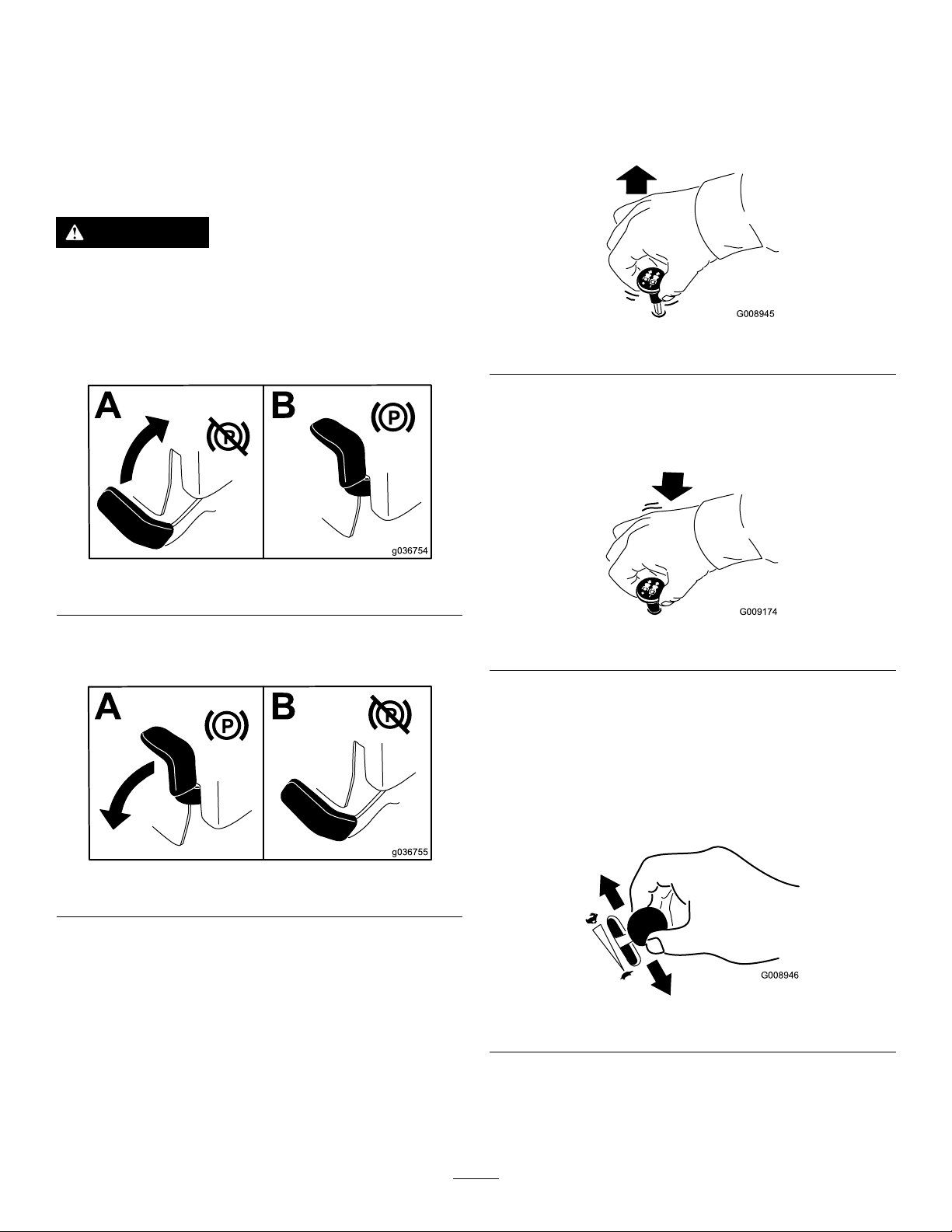
EngagingtheBlade-Control
Switch(PTO)
Note:Engagingtheblade-controlswitch(PTO)with
thethrottlepositionathalforlesscausesexcessive
weartothedrivebelts.
g008945
Figure16
DisengagingtheBlade-Control
Switch(PTO)
Figure14
ReleasingtheParkingBrake
Figure15
OperatingtheMower Blade-ControlSwitch(PTO)
Theblade-controlswitch(PTO)startsandstopsthe
mowerbladesandanypoweredattachments.
g036754
g009174
Figure17
OperatingtheThrottle
YoucanmovethethrottlecontrolbetweenFASTand
SLOWpositions(Figure18).
AlwaysusetheFASTpositionwhenturningonthe
mowerdeckwiththeblade-controlswitch(PTO).
g036755
g008946
Figure18
23
Page 24

OperatingtheChoke
Usethechoketostartacoldengine.
1.Iftheengineiscold,usethechoketostartthe
engine.
2.Pullupthechokeknobtoengagethechoke
beforeusingtheignitionswitch(Figure19).
3.Pushdownthechokeknobtodisengagethe
chokeafterstartingtheengine(Figure19).
g008947
Figure20
2.TurntheignitionkeytotheSTOPpositiontoshut
offtheengine.
StartingtheEngine
1.RaisetheROPSup,lockitintoplace,sitonthe
seat,andfastentheseatbelt.
2.MovethemotioncontrolstoNEUTRAL-LOCK
position.
3.Settheparkingbrake;refertoSettingthe
ParkingBrake(page23).
Figure19
1.ONposition2.OFFposition
OperatingtheIgnition Switch
1.TurntheignitionkeytotheST ARTposition
(Figure20).
Note:Whentheenginestarts,releasethekey.
Important:Donotengagethestarterfor
morethan5secondsatatime.Iftheengine
failstostart,wait15secondsbetween
attempts.Failuretofollowtheseinstructions
canburnoutthestartermotor.
4.Movetheblade-controlswitch(PTO)totheOFF
position(Figure17).
5.Movethethrottlelevermidwaybetweenthe
g008959
SLOWandFASTpositions.
Note:Y oumayneedmultipleattemptstostart
theenginewhenyoustartitthersttimeafter
thefuelsystemhasbeenwithoutfuelcompletely.
24
Page 25

ShuttingOfftheEngine
Note:RefertoFigure40todeterminewhichengine
youhave.
CAUTION
Childrenorbystandersmaybeinjuredifthey
moveorattempttooperatethemachinewhile
itisunattended.
Alwaysremovetheignitionkeyandsetthe
parkingbrakewhenleavingthemachine
unattended,evenifjustforafewminutes.
ShuttingOffKawasakiandKohler
Engines
Lettheengineidleatslowthrottlefor60seconds
beforeturningtheignitionswitchoff.
Figure21
6.TurntheignitionkeytotheST ARTposition
(Figure22).
Note:Whentheenginestarts,releasethekey.
Important:Donotengagestarterformore
than5secondsatatime.Iftheenginefails
tostart,allowa15secondcool-downperiod
betweenattempts.Failuretofollowthese
instructionscanburnoutthestartermotor.
Note:Youmayneedtoattempttostartthe
enginemultipletimeswhenyoustartitforthe
rsttimeafterthefuelsystemhasbeenwithout
fuelcompletely.
g036838
g036839
Figure23
Figure22
1.Off3.Start
2.Run
Important:Makesurethatthefuel-shutoff
g008947
valveisclosedbeforetransportingorstoring
themachine,asfuelleakagemayoccur.Setthe
parkingbrakebeforetransporting.Removethe
keyasthefuelpumpmayrunandcausethe
batterytolosecharge.
25
Page 26

ShuttingOffToroEngines
Note:EnsurethethrottleisintheFASTposition
beforeshuttingofftheengine.
CAUTION
Machinecanspinveryrapidly.Youmaylose
controlofthemachineandinjureyourselfor
damagethemachine.
•Usecautionwhenmakingturns.
•Slowthemachinedownbeforemaking
sharpturns.
UsingtheMotion-ControlLevers
Figure24
Important:Makesurethatthefuel-shutoff
valveisclosedbeforetransportingorstoring
themachine,asfuelleakagemayoccur.Setthe
parkingbrakebeforetransporting.Removethe
keyasthefuelpumpmayrunandcausethe
batterytolosecharge.
DrivingForwardor Backward
Thethrottlecontrolregulatestheenginespeedas
measuredinrpm(revolutionsperminute).Place
thethrottlecontrolintheFASTpositionforbest
performance.Alwaysoperateinthefullthrottle
positionwhenmowing.
g037049
c:\data\documentum\checkout\g004532
Figure25
1.Motion-control
lever—NEUTRAL-LOCK
position
2.Center,unlockedposition5.Frontofmachine
3.Forward
4.Backward
26
Page 27

DrivingForward
DrivingBackward
Note:Theengineshutsoffifyoumovethe
traction-controlleverswiththeparkingbrakeengaged.
Tostopthemachine,pullthemotion-controllevers
totheNEUTRALposition.
1.Releasetheparkingbrake;refertoReleasing
theParkingBrake(page23).
2.Movetheleverstothecenter,unlockedposition.
3.T ogoforward,slowlypushthemotion-control
leversforward(Figure26).
1.Movetheleverstothecenter,unlockedposition.
2.T ogobackward,slowlypullthemotion-control
leversrearward(Figure27).
g008953
Figure27
Figure26
g008952
27
Page 28

AdjustingtheHeight-of-Cut
UsingtheTransportLock
Thetransportlockhas2positions,andisusedwith
thedeck-liftpedal.ThereisaLOCKpositionand
anUNLOCKpositionforthetransportpositionofthe
mowerdeck(Figure28).
AdjustingtheHeight-of-CutPin
Adjusttheheight-of-cutfrom38to127mm(1-1/2to5
inches)in6mm(1/4inch)incrementsbymovingthe
height-of-cutpinintodifferentholelocations.
1.MovethetransportlocktotheLOCKposition.
2.Pushonthedeck-liftpedalwithyourfootand
raisethemowerdecktotheTRANSPORTposition
(alsothe127mmor5inchcutting-height
position)asshowninFigure29.
3.T oadjust,removethepinfromtheheight-of-cut
bracket(Figure29).
4.Selectaholeintheheight-of-cutbracket
correspondingtotheheight-of-cutdesired,and
insertthepin(Figure29).
5.Pushonthedecklift,pulluponthetransport
lockknob,andslowlylowerthemowerdeck.
Figure28
Transport-LockPositions
1.Transportlockknob3.UNLOCKposition—The
2.LOCKposition—The
mowerdecklocksintothe
transportposition.
mowerdeckdoesnotlock
intothetransportposition.
g036745
Figure29
1.Deck-liftpedal3.Height-of-cutpin
2.Height-of-cutholes
g037050
AdjustingtheAnti-Scalp
4.Transportlockknob
Rollers
Wheneveryouchangetheheight-of-cut,adjustthe
heightoftheanti-scalprollers.
1.Disengagetheblade-controlswitch(PTO),move
themotion-controlleverstotheNEUTRAL-LOCK
position,andsettheparkingbrake.
2.Shutofftheengine,removethekey ,andwait
forallmovingpartstostopbeforeleavingthe
operatingposition.
28
Page 29

Figure30
2500seriesmowerdeckshown
1.Anti-scalproller4.Flangenut
2.Spacer
3.Bushing
5.Bolt
NEUTRAL-LOCKposition,applytheparkingbrake,
andremovethekey.
2.Shutofftheengine,removethekey,andwaitfor
allmovingpartstostop.
3.Raisethemowertothetransportposition.
4.Removetheboltsandnutsfromeachbumper
(Figure32).
g038079
g037862
Figure32
Figure31
1500and2000seriesmowerdeckshown
1.Flangenut4.Anti-scalproller
2.Bolt
3.Bushing
5.Spacer
AdjustingtheSideBumpers
(RearDischargeMachinesOnly)
Installthesidebumpersinthetopholeswhen
operatinginaheightofcuthigherthan64mm(2-1/2
inches)andinthecenterholeswhenoperatingina
heightofcutlowerthan64mm(2-1/2inches).
Note:Whenthebumpersbecomeworn,switchthe
bumperstotheoppositesidesofthemowerandip
themover.Thisallowsthebumperstobeusedlonger
beforereplacingthem.
1.Disengagetheblade-controlswitch(PTO),turn
theignitionkeytooff,movetheleverstothe
1.Bolt3.Nut
2.Bumper
5.Moveeachbumpertothedesiredpositionand
securethemwiththeboltsandnuts.
Note:Useonlythetoporcentersetsofholesto
adjustthebumpers.Usethebottomholeswhen
g036848
switchingsides,atwhichtimetheybecomethe
topholesontheothersideofthemower.
StoppingtheMachine
Tostopthemachine,movethemotion-controllevers
toneutralandthentotheNEUTRAL-LOCKposition,
disengagetheblade-controlswitch(PTO),andturn
theignitionkeytotheOFFposition.
Settheparkingbrakewhenyouleavethemachine;
refertoSettingtheParkingBrake(page23).Remove
thekeyfromtheignitionswitch.
CAUTION
Childrenorbystandersmaybeinjuredifthey
moveorattempttooperatethemachinewhile
itisunattended.
Alwaysremovetheignitionkeyandsetthe
parkingbrakewhenleavingthemachine
unattended,evenifjustforafewminutes.
29
Page 30

UsingtheSideDischarge
Themowerhasahingedgrassdeectorthat
dispersesclippingstothesideanddowntowardthe
turf.
DANGER
Withoutagrassdeector,dischargecover,or
acompletegrass-catcherassemblymounted
inplace,youandothersareexposedtoblade
contactandthrowndebris.Contactwith
rotatingmowerblade(s)andthrowndebris
causeinjuryordeath.
•Neverremovethegrassdeectorfrom
themachinebecausethegrassdeector
routesmaterialdowntowardtheturf.Ifthe
grassdeectoriseverdamaged,replaceit
immediately.
•Neverputyourhandsorfeetunderthe
mower.
•Nevertrytoclearthedischargearea
ormowerbladesunlessyoumovethe
blade-controlswitch(PTO)totheOFF
position,rotatetheignitionkeytotheOFF
position,andremovethekey.
•Makesurethatthegrassdeectorisinthe
downposition.
grassissparse,oritislatefallwhengrassgrows
moreslowly.
AlternatingtheMowingDirection
Alternatethemowingdirectiontokeepthegrass
standingstraight.Thisalsohelpsdisperseclippings
whichenhancesdecompositionandfertilization.
MowingatCorrectIntervals
Grassgrowsatdifferentratesatdifferenttimesof
theyear.T omaintainthesamecuttingheight,mow
moreofteninearlyspring.Asthegrassgrowthrate
slowsinmidsummer,mowlessfrequently.Ifyou
cannotmowforanextendedperiod,rstmowata
highcuttingheight,thenmowagain2dayslaterata
lowerheightsetting.
UsingaSlowerCuttingSpeed
Toimprovecutquality ,useaslowergroundspeed
incertainconditions.
AvoidingCuttingTooLow
Whenmowinguneventurf,raisethecuttingheight
toavoidscalpingtheturf.
StoppingtheMachine
OperatingTips
UsingtheFastThrottleSetting
Forbestmowingandmaximumaircirculation,operate
theengineattheFASTposition.Airisrequiredto
thoroughlycutgrassclippings,sodonotsetthe
height-of-cutsolowastototallysurroundthemower
inuncutgrass.Alwaystrytohave1sideofthemower
freefromuncutgrass,whichallowsairtobedrawn
intothemower.
CuttingaLawnfortheFirstTime
Cutgrassslightlylongerthannormaltoensurethat
thecuttingheightofthemowerdoesnotscalpany
unevenground.However,thecuttingheightusedin
thepastisgenerallythebestonetouse.Whencutting
grasslongerthan15cm(6inches)tall,youmaywant
tocutthelawntwicetoensureanacceptablequality
ofcut.
CuttingaThirdoftheGrassBlade
Itisbesttocutonlyaboutathirdofthegrassblade.
Cuttingmorethanthatisnotrecommendedunless
Ifyoumuststoptheforwardmotionofthemachine
whilemowing,aclumpofgrassclippingsmay
dropontoyourlawn.Toavoidthis,moveontoa
previouslycutareawiththebladesengagedoryou
candisengagethemowerdeckwhilemovingforward.
KeepingtheUndersideofthe
MowerClean
Cleanclippingsanddirtfromtheundersideofthe
moweraftereachuse.Ifgrassanddirtbuildupinside
themower,cuttingqualitywilleventuallybecome
unsatisfactory.
MaintainingtheBlade(s)
Maintainasharpbladethroughoutthecuttingseason
becauseasharpbladecutscleanlywithouttearingor
shreddingthegrassblades.Tearingandshredding
turnsgrassbrownattheedges,whichslowsgrowth
andincreasesthechanceofdisease.Checkthe
mowerbladesaftereachuseforsharpness,and
foranywearordamage.Filedownanynicksand
sharpenthebladesasnecessary.Ifabladeis
damagedorworn,replaceitimmediatelywitha
genuineT ororeplacementblade.
30
Page 31

AfterOperation
AfterOperationSafety
GeneralSafety
•Cleangrassanddebrisfromthecuttingunits,
mufers,andenginecompartmenttohelpprevent
res.Cleanupoilorfuelspills.
•Shutoffthefuelbeforestoringortransportingthe
machine.
•Disengagethedrivetotheattachmentwhenever
youaretransportingornotusingthemachine.
•Usefull-widthrampsforloadingthemachineinto
atrailerortruck.
•Tiethemachinedownsecurelyusingstraps,
chains,cable,orropes.Bothfrontandrearstraps
shouldbedirecteddownandoutwardfromthe
machine.
•Allowtheenginetocoolbeforestoringthemachine
inanyenclosure.
•Shutoffthefuelbeforestoringortransportingthe
machine.
•Neverstorethemachineorfuelcontainerwhere
thereisanopename,spark,orpilotlight,such
asonawaterheateroronotherappliances.
g036849
g008948
Figure33
1.ONposition2.OFFposition
Usingthe
Drive-Wheel-Release
UsingtheFuel-Shutoff Valve
Thefuel-shutoffvalveislocatedbehindtheseat.
Closethefuel-shutoffvalvefortransport,maintenance,
andstorage.
Ensurethatthefuel-shutoffvalveisopenwhen
startingtheengine.
Valves
WARNING
Handsmaybecomeentangledintherotating
drivecomponentsbelowtheenginedeck,
whichcouldresultinseriousinjury.
Shutofftheengine,removethekey,andallow
allmovingpartstostopbeforeaccessingthe
drive-wheel-releasevalves.
WARNING
Theengineandhydraulic-driveunitscan
becomeveryhot.Touchingahotengineor
hydraulic-driveunitscancausesevereburns.
Allowtheengineandhydraulic-driveunits
tocoolcompletelybeforeaccessingthe
drive-wheel-releasevalves.
Thedrive-wheel-releasevalvesarelocatedontheleft
andrightsidesunderneaththeenginedeck.
1.Disengagetheblade-controlswitch(PTO),turn
theignitionkeytooff,movetheleverstothe
31
Page 32

NEUTRAL-LOCKposition,applytheparkingbrake,
andremovethekey.
2.Locatethebypassleversbehindtheseat,down
ontheleftandrightsideoftheframe.
3.T opushthemachine,movebothbypassknobs
rearwardandlockthemintoplace(Figure34).
4.Disengagetheparkingbrakebeforepushing
themachine.
WARNING
Drivingonthestreetorroadwaywithout
turnsignals,lights,reectivemarkings,ora
slow-moving-vehicleemblemisdangerous
andcanleadtoaccidents,causingpersonal
injury.
Donotdrivethemachineonapublicstreet
orroadway.
1.Ifyouareusingatrailer,connectittothetowing
vehicleandconnectthesafetychains.
2.Ifapplicable,connectthetrailerbrakes.
3.Loadthemachineontothetrailerortruck.
4.Shutofftheengine,removethekey ,setthe
brake,andclosethefuelvalve.
5.Usethemetaltie-downloopsonthemachineto
securelyfastentheittothetrailerortruckwith
straps,chains,cable,orropes(Figure35).
Figure34
1.Frontofthemachine
2.Rotatebypassreleaseknobcounterclockwisetoloosen.
3.Leverpositionforoperatingthemachine
4.Pulltheleverinthisdirectiontopushthemachine.
5.Leverpositionforpushingthemachine
6.Rotatethebypass-releaseknobclockwisetotighten.
7.Engine
8.Releaselever
5.T orunthemachine,movethebypassknobsto
theFORWARDpositionandlockthemintoplace
(Figure34).
TransportingtheMachine
Useaheavy-dutytrailerortrucktotransportthe
machine.Ensurethatthetrailerortruckhasall
necessarybrakes,lighting,andmarkingasrequired
bylaw.Pleasecarefullyreadallthesafetyinstructions.
Knowingthisinformationcouldhelpyou,yourfamily,
pets,orbystandersavoidinjury.
g035062
g036851
Figure35
1.Tie-downloops
32
Page 33

LoadingtheMachine
WARNING
Useextremecautionwhenloadingorunloadingthe
machineontoatraileroratruck.Useafull-widthramp
thatiswiderthanthemachineforthisprocedure.
Backthemachineuptherampsanddriveitforward
downtheramps(Figure36).
Figure36
1.Backthemachineupthe
ramps.
2.Drivethemachineforward
downtheramps.
Important:Donotusenarrowindividualramps
foreachsideofthemachine.
Ensurethattherampislongenoughsothattheangle
withthegrounddoesnotexceed15degrees(Figure
37).Onatground,thisrequiresaramptobeatleast
4timesaslongastheheightofthetrailerortruckbed
totheground.Asteeperanglemaycausemower
componentstogetcaughtasthemachinemovesfrom
theramptothetrailerortruck.Steeperanglesmay
alsocausethemachinetotiporlosecontrol.Ifyou
areloadingthemachineonornearaslope,position
thetrailerortrucksothatitisonthedownsideof
theslopeandtherampextendsuptheslope.This
minimizestherampangle.
Loadingamachineontoatrailerortruck
increasesthepossibilityofatip-overand
couldcauseseriousinjuryordeath.
•Useextremecautionwhenoperatinga
machineonaramp.
•EnsurethattheROPSisintheupposition
andusetheseatbeltwhenloadingor
unloadingthemachine.Ensurethatthe
ROPSclearsthetopofanenclosedtrailer.
•Useonlyafull-widthramp;donotuse
g028043
individualrampsforeachsideofthe
machine.
•Donotexceeda15-degreeanglebetween
therampandthegroundorbetweenthe
rampandthetrailerortruck.
•Ensurethatthelengthoframpisatleast4
timesaslongastheheightofthetraileror
truckbedtotheground.Thisensuresthat
rampangledoesnotexceed15degreeson
atground.
•Backthemachineuptherampsanddrive
itforwarddowntheramps.
•Avoidsuddenaccelerationordeceleration
whiledrivingthemachineonarampasthis
couldcausealossofcontroloratip-over.
33
Page 34

Figure37
g027996
1.Full-widthrampinstowed
position
2.Sideviewoffull-width
rampinloadingposition
3.Notgreaterthan
15degrees
4.Therampisatleast4
timesaslongastheheight
ofthetrailerortruckbed
totheground.
5.H=heightofthetraileror
truckbedtotheground
6.Trailer
34
Page 35

Maintenance
RecommendedMaintenanceSchedule(s)
MaintenanceService
Interval
Aftertherst5hours
Aftertherst75hours
Beforeeachuseordaily
Every25hours
Every50hours
MaintenanceProcedure
•ForToroengines—changetheengineoilandlter.
•Changethehydraulic-systemltersanduid.
•Checkthesafety-interlocksystem.
•ForKawasakiengines—checktheengine-oillevel.
•ForKohlerengines—checktheaircleanerfordirty,looseordamagedparts.
•ForKohlerengines—checktheengine-oillevel.
•Cleantheblowerhousing(moreoftenunderdusty,dirtyconditions).
•ForToroengines—checktheengine-oillevel.
•Checktheseatbelt.
•Checktherollover-protection-system(ROPS)knobs.
•Cleantheenginescreenandtheareaaroundtheengine.
•Cleanaroundtheengine-exhaustsystem.
•Checkthehydraulicuidlevelintheexpansiontank.
•Inspecttheblades.
•Cleanthemowerdeck.
•For1500and2000Seriesmachines—Greasethefrontcasteraxles.(moreoftenin
dirtyordustyconditions).
•ForKohlerengines—serviceorreplacetheair-cleanerfoamelement(moreoften
underdusty,dirtyconditions).
•ForToroengines—cleantheair-cleanerfoamelement(moreoftenindusty,dirty
conditions).
•For2500Seriesmachines—Greasethemowerdeck-idlerpivot.
•Greasethepump-idlerpivot.
•Checksparkarrester(ifequipped).
•Checkthetirepressure.
•Inspectthebeltsforcracksandwear.
Every100hours
Every200hours
•ForKawasakiengines—changetheengineoil(moreoftenindirtyordusty
conditions).
•ForKawasakiengines—replaceorcleanandgapthesparkplug.
•ForKohlerengines—replacetheair-cleanerpaperelement(moreoftenunderdusty ,
dirtyconditions).
•ForKohlerengines—changetheengineoilandtheengine-oillter.
•ForKohlerengines—cleanthecoolingns(moreoftenunderdusty,dirtyconditions).
•ForToroengines—replacetheair-cleanerfoamelement(moreoftenindusty,
dirtyconditions).
•ForToroengines—servicetheair-cleanerpaperelement(moreoftenindusty ,
dirtyconditions).
•ForToroengines—changetheengineoilandoillter(moreoftenindusty,dirty
conditions).
•ForToroengines—checkthesparkplug(s).
•ForKawasakiengines—changetheengine-oillter(moreoftenindirtyordusty
conditions).
•ForKohlerengines—checkthesparkplug(s).
•ForToroengines—replacetheair-cleanerpaperelement(moreoftenindusty,
dirtyconditions).
•ForToroengines—replacethesparkplug(s).
35
Page 36

MaintenanceService
Every250hours
Interval
MaintenanceProcedure
•ForKawasakiengines—replacetheprimaryairlter(moreoftenindustyorsandy
conditions).
•ForKawasakiengines—checkthesafetyairlter.
•Aftertheinitialchange—changethehydraulic-systemltersanduidwhenusing
Mobil115W50uid(changeitmoreoftenundersevereconditions).
Every300hours
Every500hours
Monthly
Yearly
Yearlyorbeforestorage
•ForKawasakiengines—Checkandadjustthevalveclearance.SeeanAuthorized
ServiceDealer.
•ForKawasakiengines—replacethesafetyairlter.
•ForKohlerengines—Checkandadjustthevalveclearance.SeeanAuthorized
ServiceDealer.
•ForKohlerengines—replacethesparkplug(s).
•Replacetheemissions-airintakelter.
•Replacethefuellter(moreoftenindusty,dirtyconditions).
•Checktheparkingbrakeadjustment.
•Aftertheinitialchange—changethehydraulic-systemltersanduidwhenusing
Toro®HYPR-OIL™500oil(changeitmoreoftenundersevereconditions).
•Checkthebatterycharge.
•For2500Seriesmachines—Lubricatethecaster-wheelhubs.
•Paintchippedsurfaces.
•Checkallmaintenanceprocedureslistedabovebeforestorage.
CAUTION
Ifyouleavethekeyintheignitionswitch,someonecouldaccidentlystarttheengineand
seriouslyinjureyouorotherbystanders.
Removethekeyfromtheignitionbeforeyoudoanymaintenance.
36
Page 37

Pre-Maintenance
Procedures
MaintenanceandStorage
•Beforerepairingthemachinedothefollowing:
–Disengagethedrives.
–Settheparkingbrake.
–Shutofftheengineandremovethekey.
–Disconnectthespark-plugwire.
•Parkthemachineonalevelsurface.
•Cleangrassanddebrisfromthecuttingunit,drives,mufers,andenginetohelppreventres.
•Cleanupoilorfuelspills.
•Lettheenginecoolbeforestoringthemachine.
•Donotstorethemachineorfuelnearamesordrainthefuelindoors.
•Donotallowuntrainedpersonneltoservicethemachine.
•Usejackstandstosupportthemachineand/orcomponentswhenrequired.
•Carefullyreleasepressurefromcomponentswithstoredenergy.
•Disconnectthebatteryorremovethespark-plugwirebeforemakinganyrepairs.Disconnectthenegative
terminalrstandthepositiveterminallast.Connectthepositiveterminalrstandnegativelast.
•Usecarewhencheckingtheblades.Wraptheblade(s)orwearthicklypaddedgloves,andusecaution
whenservicingthem.Onlyreplaceblades;donotstraightenorweldthem.
•Keephandsandfeetawayfrommovingparts.Ifpossible,donotmakeadjustmentswiththeenginerunning.
•Keepallpartsingoodworkingconditionandallhardwaretightened,especiallytheblade-attachmentbolts.
Replaceallwornordamageddecals.
•Neverinterferewiththeintendedfunctionofasafetydeviceorreducetheprotectionprovidedbyasafety
device.Checktheirproperoperationregularly.
•Toensureoptimumperformanceandcontinuedsafetycerticationofthemachine,useonlygenuineT oro
replacementpartsandaccessories.Replacementpartsandaccessoriesmadebyothermanufacturers
couldbedangerous,andsuchusecouldvoidtheproductwarranty.
•Checktheparkingbrakeoperationfrequently.Adjustandserviceasrequired.
37
Page 38

Lubrication
GreasingtheMachine
Greasemorefrequentlywhenoperatingconditions
areextremelydustyorsandy.
GreaseType:No.2lithiumormolybdenumgrease
1.Disengagetheblade-controlswitch(PTO),move
themotion-controlleverstotheNEUTRAL-LOCK
position,andsettheparkingbrake.
2.Shutofftheengine,removethekey ,andwait
forallmovingpartstostopbeforeleavingthe
operatingposition.
3.Cleanthegreasettingswitharag.
Note:Makesuretoscrapeanypaintoffthe
frontofthetting(s).
4.Connectagreaseguntothetting,andpump
greaseintothettings.
5.Wipeupanyexcessgrease.
ServiceInterval:Every25hours—For1500and
2000Seriesmachines—Greasethe
frontcasteraxles.(moreoftenin
dirtyordustyconditions).
Every50hours—For2500Series
machines—Greasethemowerdeck-idler
pivot.
Every50hours—Greasethepump-idlerpivot.
1.Disengagetheblade-controlswitch(PTO),move
themotion-controlleverstotheNEUTRAL-LOCK
position,andsettheparkingbrake.
2.Shutofftheengine,removethekey ,andwait
forallmovingpartstostopbeforeleavingthe
operatingposition.
3.Greasethemowerdeckandpumpidler-pulley
pivotwith1or2pumpsofgrease(Figure38).
4.For1500and2000Seriesmachines,greasethe
frontcasteraxles(Figure38).
Figure38
1.Pump-idlerpivot3.Mowerdeckidler-pulley
pivot(2500Series
machinesonly)
2.Casteraxle(1500and
2000Seriesmachines
only)
g037570
38
Page 39

Lubricatingthe Caster-WheelHubs
2500SeriesMachinesOnly
ServiceInterval:Yearly—For2500Series
machines—Lubricatethe
caster-wheelhubs.
1.Shutofftheengine,waitforallmovingpartsto
stop,removethekey ,andengagetheparking
brake.
Figure39
1.Sealguard2.Spacernutwithwrench
ats
11.Withtheopenendofthewheelfacingup,ll
theareainsidethewheelaroundtheaxlefullof
general-purposegrease.
12.Insertthesecondbearingandnewsealintothe
wheel.
13.Applyathread-lockingcompoundtothesecond
spacernutandthreaditontotheaxlewiththe
wrenchatsfacingoutward.
14.T orquethenutto8to9N∙m(75to80in-lb),
loosenthenut,thentorqueitto2to3N∙m(20
to25in-lb).
Note:Makesurethattheaxledoesnotextend
beyondeithernut.
15.Installthesealguardsoverthewheelhuband
insertwheelintothecasterfork.
16.Installthecasterboltandtightenthenutfully.
Important:Topreventsealandbearingdamage,
checkthebearingadjustmentoften.Spinthe
g006115
castertire.Thetireshouldnotspinfreely(more
than1or2revolutions)orhaveanysideplay.If
thewheelspinsfreely,adjustthetorqueonthe
spacernutuntilthereisaslightamountofdrag.
Applyanotherlayerofthread-lockingcompound.
2.Removethecasterwheelfromthecasterforks.
3.Removethesealguardsfromthewheelhub.
4.Removeaspacernutfromtheaxleassemblyin
thecasterwheel.
Note:Thread-lockingcompoundhasbeen
appliedtolockthespacernutstotheaxle.
5.Removetheaxle(withtheotherspacernutstill
assembledtoit)fromthewheelassembly.
6.Pryoutsealsandinspectbearingsforwearor
damageandreplaceifnecessary.
7.Packthebearingswithageneral-purpose
grease.
8.Insert1bearingand1newsealintothewheel.
Note:Replacetheseals.
9.Ifbothspacernutshavebeenremoved(or
brokenloose)fromtheaxleassembly,applya
thread-lockingcompoundto1spacernutand
threaditontotheaxlewiththewrenchats
facingoutward.
Note:Donotthreadthespacernutallof
thewayontotheendoftheaxle.Leave
approximately3mm(1/8inch)fromtheouter
surfaceofthespacernuttotheendoftheaxle
insidethenut.
10.Inserttheassemblednutandaxleintothewheel
onthesidewiththenewsealandbearing.
39
Page 40

EngineMaintenance
Usethefollowinggraphictoidentifytheengineyouhaveandproceedtothesectionlistedbelowforservice
(Figure40).
Figure40
1.Kawasakiengine2.Kohlerengine3.Toroengine
g036852
•ForKawasakienginemaintenance,referto
ServicingaKawasaki
®
Engine(page41).
•ForKohlerenginemaintenance,refertoServicing
aKohler
®
Engine(page46).
•ForToroenginemaintenance,refertoServicinga
ToroEngine(page50).
WARNING
Contactwithhotsurfacesmaycausepersonalinjury.
Keepyourhands,feet,face,clothingandotherbodypartsawaythemuferandotherhot
surfaces.
EngineSafety
Shutofftheenginebeforecheckingtheoiloradding
oiltothecrankcase.
40
Page 41

ServicingaKawasaki
®
Engine
ThissectionisonlyformachineswithKawasaki
engines.Ifyourenginelooksliketheoneshownin
Figure41,youhaveaKawasakiengine.
Important:Refertoyourenginemanufacturer’s
informationforadditionalmaintenance
procedures.
Figure41
g001883
Figure42
1.Air-cleanerbody4.Air-cleanercover
2.Primarylter5.Safetylter
3.Latch
4.Cleantheinsideoftheair-cleanercoverwith
compressedair.
5.Gentlyslidetheprimarylteroutofthe
air-cleanerbody(Figure42).
g036714
Note:Avoidknockingthelterintothesideof
thebody.
ServicingtheAirCleaner
ServiceInterval:Every250hours—ForKawasaki
engines—replacetheprimaryair
lter(moreoftenindustyorsandy
conditions).
Every250hours—ForKawasaki
engines—checkthesafetyairlter.
Every500hours—ForKawasaki
engines—replacethesafetyairlter.
Note:Checktheltersmorefrequentlyifthe
operatingconditionsareextremelydustyorsandy .
RemovingtheFilters
1.Disengagetheblade-controlswitch(PTO),move
themotion-controlleverstotheNEUTRAL-LOCK
position,andsettheparkingbrake.
2.Shutofftheengine,removethekey ,andwait
forallmovingpartstostopbeforeleavingthe
operatingposition.
3.Releasethelatchesontheaircleanerandpull
theair-cleanercoverofftheair-cleanerbody
(Figure42).
41
Page 42

6.Removethesafetylteronlyifyouintendto
replaceit.
Important:Donotattempttocleanthe
safetylter.Ifthesafetylterisdirty,then
theprimarylterisdamaged.Replaceboth
lters.
7.Inspecttheprimarylterfordamagebylooking
intothelterwhileshiningabrightlightonthe
outsideofthelter.
Note:Holesinthelterappearasbrightspots.
Ifthelterisdamaged,discardit.
ServicingthePrimaryFilter
•Iftheprimarylterisdirty,bent,ordamaged,
replaceit.
•Donotcleantheprimarylter.
Viscosity:Seethetablebelow.
g037096
Figure43
ServicingtheSafetyFilter
Replacethesafetylter,nevercleanit.
Important:Donotattempttocleanthesafety
lter.Ifthesafetylterisdirty,thentheprimary
lterisdamaged.Replacebothlters.
InstallingtheFilters
Important:Topreventenginedamage,always
operatetheenginewithbothairltersandthe
coverinstalled.
1.Ifinstallingnewlters,checkeachlterfor
shippingdamage.
Note:Donotuseadamagedlter.
2.Ifyouarereplacingthesafetylter,carefully
slideitintothelterbody(Figure42).
3.Carefullyslidetheprimarylteroverthesafety
lter(Figure42).
Note:Ensurethattheprimarylterisfully
seatedbypushingonitsouterrimwhileinstalling
it.
Important:Donotpressonthesoftinside
areaofthelter.
4.Installtheair-cleanercoverwiththeside
indicatedasupfacingupwardandsecurethe
latches(Figure42).
ServicingtheEngineOil
Note:Although10W-40engineoilisrecommended
formostconditions,youmayneedtochangeoil
viscositytoaccommodateatmosphericconditions.
Using20W-50engineoilinhigherambient
temperaturescanreduceoilconsumption.
CheckingtheEngine-OilLevel
ServiceInterval:Beforeeachuseordaily
Note:Checktheoilwhentheengineiscold.
WARNING
Contactwithhotsurfacesmaycausepersonal
injury.
Keephands,feet,face,clothing,andother
bodypartsawayfromthemuferandother
hotsurfaces.
Important:Donotoverllthecrankcasewithoil
becausethatcoulddamageengine.Donotrun
enginewithoilbelowtheLowmarkbecausethe
enginemaybedamaged.
1.Disengagetheblade-controlswitch(PTO),move
themotion-controlleverstotheNEUTRAL-LOCK
position,andsettheparkingbrake.
2.Shutofftheengine,removethekey ,andwait
forallmovingpartstostopbeforeleavingthe
operatingposition(Figure44).
OilType:Detergentoil(APIserviceSF,SG,SH,SJ,
orSL)
CrankcaseCapacity:withalterchange,2.1L(71
oz);withoutalterchange,1.8L(61oz)
42
Page 43

ChangingtheEngineOil
ServiceInterval:Every100hours(moreoftenindirty
ordustyconditions).
Note:Disposeoftheusedoilatarecyclingcenter.
1.Starttheengineandletitrunfor5minutes.
g036856
2.Parkthemachinesothattherearisslightly
lowerthanthefronttoensurethattheoildrains
completely.
3.Disengagetheblade-controlswitch(PTO),move
themotion-controlleverstotheNEUTRAL-LOCK
position,andsettheparkingbrake.
4.Shutofftheengine,removethekey ,andwait
forallmovingpartstostopbeforeleavingthe
operatingposition(Figure45).
g036856
Note:Thiswarmstheoilsothatitdrainsbetter.
Figure44
g225269
g225280
Figure45
43
Page 44

5.Slowlypourapproximately80%ofthespecied
oilintothellertubeandslowlyaddthe
additionaloiltobringittotheFullmark(Figure
46).
ChangingtheEngine-OilFilter
ServiceInterval:Every200hours—ForKawasaki
engines—changetheengine-oil
lter(moreoftenindirtyordusty
conditions).
1.Draintheoilfromtheengine;refertoChanging
theEngineOil(page43).
2.Changetheengine-oillter(Figure47).
g036856
Figure46
6.Starttheengineanddrivetoaatarea.
7.Checktheoillevelagain.
g027660
g027477
Figure47
Note:Ensurethattheoil-ltergaskettouches
theengine,andthenturntheoillteranextra
3/4turn.
3.Fillthecrankcasewiththepropertypeofnew
oil;refertoServicingtheEngineOil(page42).
44
Page 45

ServicingtheSparkPlug
CheckingtheSparkPlug
ServiceInterval:Every100hours
Makesurethattheairgapbetweenthecenterand
sideelectrodesiscorrectbeforeinstallingthespark
plug.Useasparkplugwrenchforremovingand
installingthesparkplug(s)andagappingtool/feeler
gaugetocheckandadjusttheairgap.Installanew
sparkplug(s)ifnecessary.
TypeofSparkPlug:NGK
®
BPR4ESorequivalent
AirGap:0.76mm(0.03inch)
RemovingtheSparkPlug
1.Shutofftheengine,removethekey ,andwait
forallmovingpartstostopbeforeleavingthe
operatingposition.
2.Disengagetheblade-controlswitch(PTO),move
themotion-controlleverstotheNEUTRAL-LOCK
position,andsettheparkingbrake.
3.Locateandremovethesparkplugs(Figure48).
Important:Donotcleanthesparkplug(s).
Alwaysreplacethesparkplug(s)whenithas:a
blackcoating,wornelectrodes,anoilylm,or
cracks.
Ifyouseelightbrownorgrayontheinsulator,the
engineisoperatingproperly.Ablackcoatingonthe
insulatorusuallymeanstheaircleanerisdirty .
Setthegapto0.76mm(0.03inch).
g027479
Figure49
InstallingtheSparkPlug
Figure48
Tightenthesparkplug(s)to22N∙m(16ft-lb).
g036857
g027478
g027735
Figure50
45
Page 46

ServicingaKohler
ThissectionisonlyformachineswithKohlerengines.
IfyourenginelooksliketheoneshowninFigure51,
youhaveaKohlerengine.
®
Engine
Important:Refertoyourenginemanufacturer’s
informationforadditionalmaintenance
procedures.
Figure51
2.Removethecovertoaccesstheair-cleaner
elements(Figure52).
g028105
Figure52
1.Air-cleanercover2.Air-cleanerlatch
3.Removethefoamandpaperelements(Figure
g036713
53).
4.Removethefoamelementfromthepaper
element(Figure53).
ServicingtheAirCleaner
ServiceInterval:Beforeeachuseordaily—For
Kohlerengines—checktheair
cleanerfordirty ,looseordamaged
parts.
Every25hours—ForKohlerengines—service
orreplacetheair-cleanerfoamelement(more
oftenunderdusty ,dirtyconditions).
Every100hours—ForKohlerengines—replace
theair-cleanerpaperelement(moreoftenunder
dusty,dirtyconditions).
Thisengineisequippedwithareplaceable,
high-densitypaperandfoamair-cleanerelement.
Checktheaircleanerdailyorbeforestartingthe
engine.Checkforabuildupofdirtanddebrisaround
theair-cleanersystem.Keepthisareaclean.Also,
checkforlooseordamagedcomponents.Replaceall
bentordamagedair-cleanercomponents.
Note:Operatingtheenginewithlooseordamaged
air-cleanercomponentscouldallowunlteredairinto
theengine,causingprematurewearandfailure.
g028106
Figure53
1.Air-cleanercover3.Paperelement
2.Foamelement
ServicingtheFoamElement
1.Washthefoamelementinwarmwaterand
detergent.
2.Rinseandallowittoairdry.
3.Lightlyoilthefoamelementwithnewoiland
squeezeoutexcessoil.
Note:Servicetheaircleanermoreoftenunderdusty,
dirtyconditions.
RemovingtheElements
1.Rotatethelatchesoutward.
ServicingthePaperElement
1.Gentlytapthepaperelementtodislodgedirt.
Note:Donotwashthepaperelementoruse
pressurizedair,asthiswilldamagetheelement.
46
Page 47

Note:Replaceadirty,bent,ordamaged
element.Handlethenewelementcarefully;
donotuseifthesealingsurfacesarebentor
damaged.
2.Cleantheair-cleanerbaseasrequired,and
checkthecondition.
InstallingtheElements
1.Installthefoamelementontothepaperelement.
2.Installtheelementsontotheair-cleanerbase
(Figure53).
3.Installthecover,andsecureitwiththelatches
(Figure52).
ServicingtheEngineOil
OilType:Detergentoil(APIserviceSJorhigher)
CrankcaseCapacity:1.9L(64oz)whenthelter
ischanged
Viscosity:Seethetablebelow.
Figure54
CheckingtheEngine-OilLevel
ServiceInterval:Beforeeachuseordaily
1.Parkthemachineonalevelsurface,disengage
theblade-controlswitch,shutofftheengine,
andremovethekey.
2.Makesurethattheengineisshutoff,level,and
iscool,sotheoilhastimetodrainintothesump.
3.Checktheengine-oillevel(Figure55).
g027515
Figure55
ChangingtheEngineOilandtheEngine-Oil
Filter
ServiceInterval:Every100hours—ForKohler
engines—changetheengineoiland
theengine-oillter.
g017552
Note:Thedrainplugisattachedtothedrainhose.
Note:Disposeoftheusedoilatarecyclingcenter.
Fillwithoilasspeciedinthe“ViscosityGrades”table
(Figure54).
1.Parkthemachine,sothatthedrainsideis
slightlylowerthantheoppositeside,toensure
thattheoildrainscompletely.
2.Disengagetheblade-controlswitchandmove
themotioncontrolsoutwardtothePARKposition.
3.Shutofftheengine,removethekey ,andwait
forallmovingpartstostopbeforeleavingthe
operatingposition.
47
Page 48

Figure56
g027934
4.T orquetheplugto14N∙m(10ft-lb).
5.Changetheengine-oillterasshowninFigure
57.
g038074
Figure57
6.Slowlypourapproximately80%ofthespecied
oilintothellertube(Figure58).
48
Page 49

Figure58
ServicingtheSparkPlug
ServiceInterval:Every200hours—ForKohler
engines—checkthesparkplug(s).
Every500hours—ForKohlerengines—replace
thesparkplug(s).
g027478
Figure59
CheckingtheSparkPlug
Important:Donotcleanthesparkplug(s).
Alwaysreplacethesparkplug(s)whenithas:a
blackcoating,wornelectrodes,anoilylm,or
cracks.
Note:Ifyouseelightbrownorgrayontheinsulator,
theengineisoperatingproperly.Ablackcoatingon
theinsulatorusuallymeanstheaircleanerisdirty.
Setthegapto0.76mm(0.03inch).
g027517
g027479
Figure60
ThesparkplugisRFIcompliant.Equivalentalternate
brandplugscanalsobeused.
Type:ChampionXC12YC
AirGap:0.76mm(0.03inch)
RemovingtheSparkPlug
1.Disengagetheblade-controlswitch,movethe
motioncontrolsoutwardtotheparkposition,
shutofftheengine,andremovethekey .
2.Beforeremovingthesparkplug(s),cleanthe
areaaroundthebaseoftheplugtokeepdirt
anddebrisoutoftheengine.
3.Removethesparkplug(Figure59).
49
Page 50

InstallingtheSparkPlug
Tightenthesparkplugto27N∙m(20ft-lb)asshown
inFigure61.
Figure61
ServicingaToroEngine
ThissectionisonlyformachineswithToroengines.
IfyourenginelookslikewhatisshowninFigure62,
youhaveaT oroengine.
g036715
Figure62
g028109
ServicingtheAirCleaner
CleaningtheBlowerHousing
Every100hours/Y early(whichevercomes
rst)—ForKohlerengines—cleanthecooling
ns(moreoftenunderdusty,dirtyconditions).
Toensurepropercooling,ensurethatthegrass
screen,coolingns,andotherexternalsurfacesofthe
enginearekeptcleanatalltimes.
ForKohlerengines,removetheblowerhousing,and
anyothercoolingshrouds.Cleanthecoolingnsand
externalsurfacesasnecessary.Makesurethatthe
coolingshroudsareinstalled.
Important:Operatingtheenginewithablocked
grassscreen,dirtyorpluggedcoolingns,and/or
coolingshroudsremoved,willcauseengine
damageduetooverheating.
ServiceInterval:Every25hours/Monthly
(whichevercomesrst)—For
Toroengines—cleantheair-cleaner
foamelement(moreoftenindusty,
dirtyconditions).
Every100hours/Y early(whichevercomes
rst)—ForToroengines—replacethe
air-cleanerfoamelement(moreoftenindusty,
dirtyconditions).
Every100hours/Y early(whichevercomes
rst)—ForToroengines—servicetheair-cleaner
paperelement(moreoftenindusty,dirty
conditions).
Every200hours/Every2years(whichever
comesrst)—ForT oroengines—replacethe
air-cleanerpaperelement(moreoftenindusty,
dirtyconditions).
RemovingtheElements
1.Parkthemachineonalevelsurfaceand
disengagetheblade-controlswitch(PTO).
2.Engagetheparkingbrake,shutofftheengine,
removethekey,andwaitforallmovingpartsto
stopbeforeleavingtheoperatingposition.
3.Cleanaroundtheair-cleanercovertoprevent
dirtfromgettingintotheengineandcausing
damage.
4.Liftthecoverandrotatetheair-cleanerassembly
outoftheengine(Figure63).
50
Page 51

Important:Donotcleanthepaperelement
withpressurizedairorliquids,suchas
solvent,gas,orkerosene.Replacethepaper
elementifitisdamagedorcannotbecleaned
thoroughly.
ServicingtheEngineOil
OilType:Detergentoil(APIserviceSF,SG,SH,SJ,
orSL)
Figure63
5.Removethefoamelementfromthepaper
element(Figure64).
g027800
CrankcaseCapacity:2.4L(80oz)withoillter
Viscosity:Seethetablebelow.
g029683
Figure65
g027801
CheckingtheEngine-OilLevel
ServiceInterval:Beforeeachuseordaily—ForT oro
engines—checktheengine-oillevel.
Note:Checktheoilwhentheengineiscold.
Figure64
ServicingtheFoamElement
Washthefoamelementwithwaterandreplaceitif
itisdamaged.
ServicingthePaperElement
1.Lightlytaptheelementonaatsurfaceto
removedustanddirt.
2.Inspecttheelementfortears,anoilylm,and
damagetotheseal.
WARNING
Contactwithhotsurfacesmaycausepersonal
injury.
Keephands,feet,face,clothing,andother
bodypartsawaythemuferandotherhot
g027802
surfaces.
Important:Donotoverllthecrankcasewithoil,
becausedamagetotheenginemayresult.Donot
runenginewithoilbelowtheLowmark,because
theenginemaybedamaged.
1.Parkthemachineonalevelsurface,disengage
theblade-controlswitch,shutofftheengine,
engagetheparkingbrake,andremovethekey.
2.Makesurethattheengineisshutoff,level,and
iscoolsothattheoilhashadtimetodraininto
thesump.
3.T okeepdirt,grassclippings,etc.,outofthe
engine,cleantheareaaroundtheoil-llcapand
dipstickbeforeremovingit(Figure66).
51
Page 52

Figure66
g027799
g029368
ChangingtheEngineOilandOilFilter
ServiceInterval:Aftertherst5hours/Aftertherst
month(whichevercomesrst)—For
Toroengines—changetheengine
oilandlter.
Every100hours/Y early(whichevercomes
rst)—ForT oroengines—changetheengine
oilandoillter(moreoftenindusty,dirty
conditions).
Note:Disposeoftheusedoilatarecyclingcenter.
1.Parkthemachineonalevelsurfacetoensure
theoildrainscompletely.
2.DisengagethePTOandengagetheparking
brake.
3.Shutofftheengine,removethekey ,andwait
forallmovingpartstostopbeforeleavingthe
operatingposition.
4.Draintheengineoil(Figure67).
g029570
Figure67
52
Page 53

5.Changetheengine-oillter(Figure68).
6.Slowlypourapproximately80%ofthespecied
oilintothellertubeandslowlyaddthe
additionaloiltobringittotheFullmark(Figure
69).
Figure68
Note:Ensurethattheoil-ltergaskettouches
theengineandthenturnthelteranextra3/4
turn.
g027484
Figure69
g027477
ServicingtheSparkPlug
ServiceInterval:Every100hours/Yearly
(whichevercomesrst)—For
Toroengines—checkthespark
plug(s).
Every200hours/Every2years(whichever
comesrst)—ForT oroengines—replacethe
sparkplug(s).
Makesurethattheairgapbetweenthecenterand
sideelectrodesiscorrectbeforeinstallingthespark
plug.Useaspark-plugwrenchtoremoveandinstall
thesparkplug(s)andagappingtool/feelergaugeto
checkandadjusttheairgap.Installanewspark
plug(s)ifnecessary.
Type:ChampionRN9YCorNGKBPR6ES
Airgap:0.76mm(0.03inch)
53
Page 54

RemovingtheSparkPlug
InstallingtheSparkPlug
1.DisengagethePTOandengagetheparking
brake.
2.Shutofftheengine,removethekey ,andwait
forallmovingpartstostopbeforeleavingthe
operatingposition.
Figure70
Note:Duetothedeeprecessaroundthespark
plug,blowingoutthecavitywithcompressedair
isusuallythemosteffectivemethodforcleaning.
Thesparkplugismostaccessiblewhenthe
blowerhousingisremovedforcleaning.
CheckingtheSparkPlug
Tightenthesparkplug(s)to25to30N∙m(19to22
ft-lb).
g027478
g027735
Figure72
Important:Donotcleanthesparkplug(s).
Alwaysreplacethesparkplug(s)whenithas:a
blackcoating,wornelectrodes,anoilylm,or
cracks.
Ifyouseelightbrownorgrayontheinsulator,the
engineisoperatingproperly.Ablackcoatingonthe
insulatorusuallymeanstheaircleanerisdirty .
Setthegapto0.76mm(0.030inch).
Figure71
CleaningtheCoolingSystem
Cleantheair-intakescreenfromgrassanddebris
beforeeachuse.
1.Disengagetheblade-controlswitchandengage
theparkingbrake.
2.Shutofftheengine,removethekey ,andwait
forallmovingpartstostopbeforeleavingthe
operatingposition.
3.Removetheairlterfromtheengine.
4.Removetheengineshroud.
5.T opreventdebrisenteringtheairintake,install
theairltertothelterbase.
6.Cleandebrisandgrassfromtheparts.
g027479
7.Removetheairlterandinstalltheengine
shroud.
8.Installtheairlter.
54
Page 55

CheckingtheSpark
FuelSystem
Arrester
ForMachineswithaSpark
Arrester
ServiceInterval:Every50hours
WARNING
Hotexhaustsystemcomponentsmayignite
gasolinevaporsevenafteryoushutoffthe
engine.Hotparticlesexhaustedduringengine
operationmayigniteammablematerials.
Firemayresultinpersonalinjuryorproperty
damage.
Donotrefuelorruntheengineunlessaspark
arresterisinstalled.
1.Shutofftheengine,waitforallmovingpartsto
stop,andremovekey.Engageparkingbrake.
2.Waitformufertocool.
3.Ifthereareanybreaksinthescreenorwelds,
replacethearrester.
4.Ifthescreenisplugged,removethearrester
andshakethelooseparticlesoutofthearrester
andcleanthescreenwithawirebrush(soakit
insolventifnecessary).Installthearresteron
theexhaustoutlet.
Maintenance
ReplacingtheFuelFilter
ServiceInterval:Every500hours/Yearly(whichever
comesrst)(moreoftenindusty,
dirtyconditions).
Important:Installthefuellinehosesandsecure
withplastictiesthesameastheywereoriginally
installedatthefactorytokeepthefuellineaway
fromcomponentsthatcancausefuellinedamage.
Thefuellterislocatedneartheengineontheleft
frontoftheengine.
1.Disengagetheblade-controlswitch(PTO),move
themotion-controlleverstotheNEUTRAL-LOCK
position,andsettheparkingbrake.
2.Shutofftheengine,removethekey ,andwait
forallmovingpartstostopbeforeleavingthe
operatingposition.
3.Allowthemachinetocooldown.
4.Closethefuel-shutoffvalveundertheseat
(Figure33).
Replacingthe Emissions-AirIntakeFilter
ServiceInterval:Every500hours
1.Shutofftheengine,waitforallmovingpartsto
stop,andremovekey.Engageparkingbrake.
2.Removethelterfromtheventhose.
3.Insertanewlterintotheendoftheventhose.
55
Page 56

Figure73
Kohlerengineltershown
ElectricalSystem
Maintenance
ElectricalSystemSafety
•Disconnectthebatterybeforerepairingthe
machine.Disconnectthenegativeterminalrst
andthepositivelast.Connectthepositiveterminal
rstandthenegativelast.
•Chargethebatteryinanopen,well-ventilated
area,awayfromsparksandames.Unplugthe
chargerbeforeconnectingordisconnectingthe
battery.Wearprotectiveclothinganduseinsulated
tools.
WARNING
CALIFORNIA
Proposition65Warning
Batteryposts,terminals,andrelated
accessoriescontainleadandlead
compounds,chemicalsknownto
theStateofCaliforniatocause
cancerandreproductiveharm.Wash
g029685
handsafterhandling.
5.Openthefuel-shutoffvalve.
ServicingtheFuelTank
Donotattempttodrainthefueltank.Ensurethatan
AuthorizedServiceDealerdrainsthefueltankand
servicesanycomponentsofthefuelsystem.
ServicingtheBattery
ServiceInterval:Monthly
DANGER
Batteryelectrolytecontainssulfuricacid,
whichisadeadlypoisonandcausessevere
burns.
Donotdrinkelectrolyteandavoidcontact
withskin,eyes,orclothing.Wearsafety
glassestoshieldyoureyesandwearrubber
glovestoprotectyourhands.
56
Page 57

RemovingtheBattery
WARNING
Batteryterminalsormetaltoolscouldshort
againstmetalmachinecomponents,causing
sparks.Sparkscancausethebatterygasses
toexplode,resultinginpersonalinjury.
•Whenremovingorinstallingthebattery,
donotallowthebatteryterminalstotouch
anymetalpartsofthemachine.
•Donotallowmetaltoolstoshortbetween
thebatteryterminalsandmetalpartsofthe
machine.
WARNING
Incorrectbatterycableroutingcoulddamage
themachineandcables,causingsparks.
Sparkscancausethebatterygassesto
explode,resultinginpersonalinjury.
g036853
•Alwaysdisconnectthenegative(black)
batterycablebeforedisconnectingthe
positive(red)cable.
•Alwaysconnectthepositive(red)battery
cablebeforeconnectingthenegative
(black)cable.
1.Disengagetheblade-controlswitch(PTO),move
themotion-controlleverstotheNEUTRAL-LOCK
position,andsettheparkingbrake.
2.Shutofftheengine,removethekey ,andwait
forallmovingpartstostopbeforeleavingthe
operatingposition.
3.Disconnectthenegativebatterycable(black)
fromthenegative(-)batteryterminal(Figure74).
4.Slidetheredterminalbootoffthepositive(red)
batteryterminal,andremovethepositive(+)
batterycable(Figure74).
5.Removetherubberstrap(Figure74).
6.Removethebattery.
g036855
Figure74
57
Page 58

InstallingtheBattery
1.Positionthebatteryinthetraywiththeterminal
postsoppositefromthehydraulictank(Figure
74).
2.Installthepositive(red)batterycabletothe
positive(+)batteryterminal.
3.Installthenegative(black)batterycableand
groundwiretothenegative(-)batteryterminal.
4.Securethecableswith2bolts,2washers,and
2locknuts(Figure74).
5.Slidetheredterminalbootontothepositive(+)
batteryterminal.
6.Securethebatterywiththerubberstrap(Figure
74).
ChargingtheBattery
1.Positivebatterypost
2.Negativebatterypost
g000960
Figure75
3.Red(+)chargerlead
4.Black(-)chargerlead
WARNING
Chargingthebatteryproducesgassesthat
canexplode.
Neversmokenearthebatteryandkeepsparks
andamesawayfromthebattery.
Important:Alwayskeepthebatteryfullycharged
(1.265specicgravity).Thisisespecially
importanttopreventbatterydamagewhenthe
temperatureisbelow0°C(32°F).
1.Chargebatteryfor10to15minutesat25to30
Aorfor30minutesat10A.
2.Whenthebatteryisfullycharged,unplug
thechargerfromtheelectricaloutlet,then
disconnectthechargerleadsfromthebattery
posts(Figure75).
3.Installthebatteryinthemachineandconnect
thebatterycables;refertoInstallingtheBattery
(page58).
Note:Donotrunthemachinewiththebattery
disconnected;electricaldamagemayoccur.
ServicingtheFuses
Theelectricalsystemisprotectedbyfuses.Itrequires
nomaintenance,however,ifafuseblowscheckthe
componentandcircuitforamalfunctionorshort.
Thefusesarelocatedontherightconsolenexttothe
seat(Figure76).
1.T oreplacethefuses,pulloutthefusetoremove
it.
2.Installanewfuse(Figure76).
g036858
Figure76
1.Fusecover
2.Fuseholder
58
3.Fuel-shutoffvalve
Page 59

DriveSystem
Maintenance
CheckingtheSeatBelt
ServiceInterval:Beforeeachuseordaily
Inspecttheseatbeltforwear,cuts,andproper
operationoftheretractorandbuckle.Replacethe
seatbeltifitisdamaged.
Checkingthe Rollover-Protection-System (ROPS)Knobs
ServiceInterval:Beforeeachuseordaily
WARNING
Toavoidinjuryordeathfromrollover,keep
therollbarinthefullyraised,lockedposition
andusetheseatbelt.
Ensurethattheseatissecuredtothe
machine.
•Checkthatboththemountinghardwareandthe
knobsareingoodworkingcondition.
•Makesurethattheknobsarefullyengagedwith
theROPSintheraisedposition.
1.Rollbarintheupright
position
2.ROPSknobinthelatched
position
3.PulltheROPSknobout
androtateit90degrees.
g036746
Figure77
4.RotatetheROPSknob90
degrees.
5.ROPSknobinthe
unlatchedposition
6.Rollbarinthefolded
position
Note:Theupperhoopoftherollbarmayneed
tobepushedforwardorpulledrearwardtofully
engagebothknobs(Figure77andFigure78).
g034593
Figure78
1.Engaged2.Partiallyengaged—donot
operatewiththeROPSin
thisposition.
59
Page 60

AdjustingtheTracking
CheckingtheTirePressure
1.Disengagetheblade-controlswitch(PTO).
2.Drivetoanopen,atareaandmovethe
motion-controlleverstotheNEUTRAL-LOCK
position.
3.MovethethrottlemidwaybetweentheFASTand
SLOWpositions.
4.Movebothmotion-controlleversforwarduntil
theybothhitthestopsintheT-slot.
5.Checkwhichwaythemachinetracks.
6.Ifthemachinetrackstotheright,inserta
3/16-inchhexwrenchthroughtheaccessholein
therightfrontcoverpanelandrotatethetracking
screwclockwiseorcounterclockwisetoadjust
thetravelofthelever(Figure79).
7.Ifthemachinetrackstotheleft,inserta
3/16-inchhexwrenchthroughtheaccessholein
therightfrontcoverpanelandrotatethetracking
screwclockwiseorcounterclockwisetoadjust
thetravelofthelever(Figure79).
8.Drivethemachineandcheckthefullforward
tracking.
9.Repeattheadjustmentuntilthedesiredtracking
isobtained.
ServiceInterval:Every50hours/Monthly(whichever
comesrst)
Maintaintheairpressureinthefrontandreartires
at90kPa(13psi).Uneventirepressurecancause
unevencut.Checkthetireswhentheyarecoldtoget
themostaccuratepressurereading.
g001055
Figure80
CheckingtheWheelLug Nuts
1.Accessholeonfrontcover
panel
Checkandtorquethewheellugnutsto122to136
N∙m(90to100ft-lb).
g035859
Figure79
Leftcontrollevershown
2.Trackingscrew
60
Page 61

CoolingSystem
Maintenance
BrakeMaintenance
AdjustingtheParking
CleaningtheEngineScreen
ServiceInterval:Beforeeachuseordaily
Beforeeachuseordaily
Beforeeachuseremoveanybuildupofgrass,dirt,or
otherdebrisfromtheenginescreen,engineexhaust,
andtheareaaroundtheengine.Thishelpsensure
adequatecoolingandcorrectenginespeedand
reducesthepossibilityofoverheatingandmechanical
damagetotheengine.
Brake
ServiceInterval:Every500hours
Note:Makesuretofollowthisprocedurewhena
brakecomponenthasbeenremovedorreplaced.
1.Drivethemachineontoalevelsurface.
2.Disengagetheblade-controlswitch(PTO),move
themotion-controlleverstotheNEUTRAL-LOCK
position,andsettheparkingbrake.
3.Shutofftheengine,removethekey ,andwait
forallmovingpartstostopbeforeleavingthe
operatingposition.
4.Setupthemachinetobepushedbyhand.Refer
toUsingtheDrive-Wheel-ReleaseValves(page
31).
5.Raisethebackofthemachineupandsupport
themachinewithjackstands.
CAUTION
Raisingthemachineforservice
ormaintenancerelyingsolelyon
mechanicalorhydraulicjackscouldbe
dangerous.Themechanicalorhydraulic
jacksmaynotbeenoughsupportormay
malfunctionallowingthemachinetofall,
whichcouldcauseinjury .
Donotrelysolelyonmechanical
orhydraulicjacksforsupport.Use
adequatejackstandsorequivalent
support.
6.Engageanddisengagetheparkingbrakeand
checkeachdrivetiretoensurethateachbrake
engagesanddisengages.
7.Ifanadjustmentisnecessary ,disengagethe
parkingbrake.Removethecotterpinfromthe
brakelinkageshaft(Figure81).
61
Page 62

Figure81
1.Cotterpin3.Brakelinkageshaft
2.Parkingbrake
8.CheckbothspringlengthsasshowninFigure
82.Ifanadjustmentisnecessary,turnthe
topnutclockwisetoshortenthespringand
counterclockwisetolengthenit.
10.Rotatethebrake-linkageshaftuntiltheend
alignswiththeholeinthelever.
•Shortenthelinkagebyturningitclockwise.
•Lengthenthelinkagebyturningit
counterclockwise.
11.Insertthebrake-linkageshaftintothe
parking-brakeholeandsecurewiththecotter
pin.Repeatstep6andadjustifnecessary.
12.Whenadjustmentiscomplete,removethejack
standsorequivalentsupportandlowerthe
machine.
13.PlacethemachineintotheOPERATINGposition.
g036752
RefertoUsingtheDrive-Wheel-ReleaseValves
(page31).
Figure82
1.Topnut
2.Spring
3.44mm(1-3/4inches)
9.Pushtheparkingbrakeleverallthewayforward
anddown.
g036100
62
Page 63

BeltMaintenance
InspectingtheBelts
ServiceInterval:Every50hours
Replacethebeltifitisworn.Thesignsofawornbelt
includesquealingwhilethebeltisrotating;theblades
slippingwhilecuttinggrass;andfrayededges,burn
marks,andcracksonthebelt.
ReplacingtheMowerBelt forSideDischargeMower Decks
1.Disengagetheblade-controlswitch(PTO),move
themotion-controlleverstotheNEUTRAL-LOCK
position,andsettheparkingbrake.
2.Shutofftheengine,removethekey ,andwait
forallmovingpartstostopbeforeleavingthe
operatingposition.
3.Lowerthemowertothe76mm(3inch)
height-of-cut.
4.Removethebeltcovers(Figure83).
Figure84
1500and2000SeriesMowerDecks
1.Clutchpulley3.Spring-loadedidlerpulley
2.Mowerbelt
4.Spring
g036861
Figure83
5.Removethespringtensionfromthe
spring-loadedidlerpulley.RefertoFigure84
orFigure86.
Note:For1500and2000Seriesmower
decks,usethespringremovaltool(T oroPart
No.92–5771)toremovethespringfromthe
mower-deckpost(Figure85).
Note:For2500Seriesmowerdecks,usea
ratchetinthesquareholeintheidlerarmto
removetensionontheidlerspring(Figure86).
6.Removethebeltfromthemower-deckpulleys
andtheclutchpulley.
7.Installthenewbeltaroundthemowerpulleys
andtheclutchpulleyundertheengine(Figure
84orFigure86).
g027729
g028279
Figure85
1500and2000SeriesMowerDecks
1.Spring-removaltool(T oro
PartNo.92–5771)
2.Idlerspring5.Mowerbelt
3.Mower-deckpost
63
4.Idlerarm
Page 64

ReplacingtheMowerBelt forRearDischargeMower Decks
ReplacingtheCounter-Rotating
Belt
1.Disengagetheblade-controlswitch(PTO),move
themotion-controlleverstotheNEUTRAL-LOCK
position,andsettheparkingbrake.
2.Shutofftheengine,removethekey ,andwait
forallmovingpartstostopbeforeleavingthe
operatingposition.
3.Lowerthemowertothe76mm(3inches)height
ofcut.
4.Lifttheoorpanuptogainaccesstothecenter
pulley.
Figure86
2500SeriesMowerDecks
1.Clutchpulley
2.Mowerbelt
3.Spring-loadedidlerpulley
4.Ratchet
5.Squareholeintheidler
armfortheratchet
8.Installtheidlerspring(Figure84orFigure86).
Note:Makesuretoseatthespringendsinthe
anchorgrooves.
9.Installthebeltcovers(Figure87).
g036865
5.Removetheplasticbeltcover(Figure89).
6.Removethe3boltsholdingthemetalbeltcover
inplaceandremovethemetalbeltcover.
g036862
Figure88
1.Idlerspring4.Idlerpulley
2.Counter-rotatingbelt5.Squareholeintheidler
3.Doublepulley
armfortheratchet
Figure87
7.Usearatchetinthesquareholeintheidlerarm
toremovetensionontheidlerspring(Figure88).
g027730
8.Removethebeltfromthemowerdeckpulley
(Figure88).
9.Removethebeltfromtheremainingpulleys
(Figure88).
10.Routethenewbeltaboundthemowerpulleys.
64
Page 65

11.Usingtheratchetinthesquarehole,removethe
tensiononthespring,andguidethenewbelt
aroundtheidlerpulley(Figure88).
ReplacingtheMowerBelt
1.Disengagetheblade-controlswitch(PTO),move
themotion-controlleverstotheNEUTRAL-LOCK
position,andsettheparkingbrake.
2.Shutofftheengine,removethekey ,andwait
forallmovingpartstostopbeforeleavingthe
operatingposition.
3.Lowerthemowertothe76mm(3inches)height
ofcut.
4.Removethebeltcovers(Figure89).
Figure89
5.Removethecounter-rotatingbelt;referto
ReplacingtheCounter-RotatingBelt(page64).
6.Usearatchetinthesquareholeintheidlerarm
toremovetensionontheidlerspring(Figure90).
7.Removethebeltfromthemower-deckpulleys
andtheclutchpulley.
8.Installthenewbeltaroundthemowerpulleys
andtheclutchpulleyundertheengine(Figure
90).
g036863
Figure90
Reardischargemowerdeckshown
1.Mowerbelt
2.Spring-loadedidlerpulley4.Counter-rotatingbelt
3.Squareholeintheidler
armfortheratchet
9.Usingtheratchetinthesquarehole,installthe
beltaroundthespring-loadedidlerpulley(Figure
90).
g009036
Makesurethatthespringendsareseatedin
theanchorgrooves.
10.Installthebeltcovers(Figure91).
g009037
Figure91
65
Page 66

ReplacingtheHydraulic Pump-DriveBelt
1.Disengagetheblade-controlswitch(PTO)and
settheparkingbrake.
2.Shutofftheengine,removethekey ,andwait
forallmovingpartstostopbeforeleavingthe
operatingposition.
3.Removethemowerbelt;refertoReplacingthe
MowerBeltforSideDischargeMowerDecks
(page63)orReplacingtheMowerBeltforRear
DischargeMowerDecks(page64).
4.Raisethemachineandsupportitwithjack
stands(Figure93).
5.Removetheclutchstop(Figure92).
Figure93
1.Idlerpulley4.Pump-drivebelt
2.Idler-springpost5.Righthydraulic-pump
3.Enginepulley
pulley
6.Lefthydraulic-pumppulley
9.Installtheclutchstop(Figure92).
g036859
Figure92
1.Clutchstop
6.Removetheidlerspringfromthepost(Figure
93).
7.Removetheexistingbeltfromthe
hydraulic-unit-drivepulleysandtheengine
pulley.
8.Installthenewbeltaroundtheenginepulleyand
the2hydraulic-pumppulleys(Figure93).
10.Installthemowerbelt;refertoBeltMaintenance
(page63).
g036860
66
Page 67

ControlsSystem
Maintenance
Adjustingthe Control-HandlePosition
1.Disengagetheblade-controlswitch(PTO),move
themotion-controlleverstotheNEUTRAL-LOCK
position,andsettheparkingbrake.
2.Shutofftheengine,removethekey ,andwait
forallmovingpartstostopbeforeleavingthe
operatingposition.
Adjustingtheheight:
Youcanadjustthemotioncontrollevershigher
orlowerformaximumcomfort.
A.Removethehardwareholdingthecontrol
levertothecontrol-armshaft.
C.Repeattheadjustmentfortheopposite
controllever.
g009195
Figure95
Figure94
1.Bolts
2.Slottedhole4.Control-armshaft
B.Movethecontrollevertothenextsetof
holes.Securetheleverwiththehardware.
C.Repeattheadjustmentfortheopposite
controllever.
AdjustingtheTilt
A.Loosentheupperboltholdingthecontrol
levertothecontrolarmshaft.
B.Loosenthelowerboltjustenoughtopivot
thecontrolleverforeoraft.Tightenboth
boltstosecurethecontrolinthenew
position.
3.Controllever
3.Iftheendsofthelevershitagainsteachother,
refertoAdjustingtheMotion-ControlLinkage
(page67).
Adjustingthe Motion-ControlLinkage
Locatedoneithersideofthemachine,belowtheseat
arethepumpcontrollinkages.Rotatingtheendnut
witha1/2inchdeepsocketwrenchallowsnetuning
adjustmentssothatthemachinedoesnotmovein
neutral.Anyadjustmentsshouldbemadeforneutral
positioningonly.
g035858
WARNING
Enginemustberunninganddrivewheels
mustbeturningsoadjustmentscanbe
performed.Contactwithmovingpartsorhot
surfacesmaycausepersonalinjury.
Keepyourngers,hands,andclothingclear
ofrotatingcomponentsandhotsurfaces.
1.Priortostartingtheengine,pushthedecklift
pedalandremovetheheightofcutpin.Lower
decktotheground.
2.Raisetherearofmachineupandsupportwith
jackstands(orequivalentsupport)justhigh
enoughtoallowdrivewheelstoturnfreely.
3.Removetheelectricalconnectionfromtheseat
safetyswitch,locatedunderthebottomcushion
oftheseat.
67
Page 68

Note:Theswitchisapartoftheseatassembly.
4.T emporarilyinstallajumperwireacrossthe
terminalsintheconnectorofthemainharness.
5.Starttheengine.Runtheengineatfullthrottle
andreleasetheparkingbrake.
Note:Ensurethattheparkingbrakeisengaged
andthatthemotion-controlleversareouttostart
theengine.Y oudonothavetobeintheseat.
6.Runthemachineatleast5minuteswiththe
driveleversinthefullforwardspeedtobring
hydraulicuiduptooperatingtemperature.
Note:Themotion-controllevermustbe
inneutralwhilemakinganynecessary
adjustments.
7.Bringthemotion-controlleversintotheNEUTRAL
position.
8.Checkandensurethatthecontrol-platetabs
touchthereturn-to-neutralplatesonthe
hydraulicunits.
g036753
Figure96
9.Adjustthepump-control-rodlengthsbyturning
thenutintheappropriatedirectionuntilthe
wheelsslightlycreepinreverse(seeFigure96).
10.Movethemotion-controlleverstotheREVERSE
positionandwhileapplyingslightpressureto
thelever,allowthereverseindicatorspringsto
bringtheleversbacktoneutral.
Note:Thewheelsmuststopturningorslightly
creepinreverse.
Note:Y oumayneedtoremovethe
motion-controlcovertogainaccess.
1.Nut4.Return-to-neutralplate
2.Stationaryplate
3.Controlplate
5.Tabstouchingreturnto
neutralplate
11.Shutoffthemachine.
12.Removethejumperwirefromthewireharness
andplugtheconnectorintotheseatswitch.
13.Removethejackstands.
14.Raisethemowerdeckandinstalltheheightof
cutpin.
15.Checkandensurethatthemachinedoesnot
creepinneutralwiththeparkbrakedisengaged.
68
Page 69

HydraulicSystem
Maintenance
HydraulicSystemSafety
•Ensurethatallhydraulic-uidhosesand
linesareingoodconditionandallhydraulic
connectionsandttingsaretightbefore
applyingpressuretothehydraulicsystem.
•Keepyourbodyandhandsawayfrompinhole
leaksornozzlesthatejecthigh-pressure
hydraulicuid.
•Usecardboardorpapertondhydraulicleaks.
•Safelyrelieveallpressureinthehydraulic
systembeforeperforminganyworkonthe
hydraulicsystem.
•Seekimmediatemedicalattentionifuid
isinjectedintoskin.Injecteduidmustbe
surgicallyremovedwithinafewhoursbya
doctor.
g037051
Figure97
1.Engine2.Expansiontank
ServicingtheHydraulic System
HydraulicFluidType:Toro
hydraulicuid(preferred)orMobil115W-50oil.
Important:Usetheuidspecied.Otheruids
couldcausesystemdamage.
HydraulicSystemCapacity(withltersremoved):
4.45L(150oz)
CheckingtheHydraulicFluidLevel
ServiceInterval:Beforeeachuseordaily
1.Allowthehydraulicuidtocooldown.Check
theoillevelwhentheoiliscold.
2.Checkexpansionreservoirandifnecessary
addT oro
FULLCOLDline.
®
HYPR-OIL
®
HYPR-OIL
™
500hydraulicuidtothe
™
500
69
Page 70

Changingthe Hydraulic-SystemFilters andFluid
ServiceInterval:Aftertherst75hours—Changethe
hydraulic-systemltersanduid.
Every500hours—Aftertheinitial
change—changethehydraulic-system
ltersanduidwhenusingT oro
500oil(changeitmoreoftenundersevere
conditions).
Every250hours—Aftertheinitial
change—changethehydraulic-system
ltersanduidwhenusingMobil115W50uid
(changeitmoreoftenundersevereconditions).
®
HYPR-OIL
™
g017444
Figure98
Rightsideshown
Changetheltersandoilatthesametime.Donot
usetheoilagain.Purgeanyairinthesystemafteryou
installthenewltersandaddoil.RefertoBleeding
theHydraulicSystem(page72).
Repeatthebleedingprocessuntiltheoilremains
attheFULLCOLDlineinthereservoirafterpurging.
Failuretoproperlyperformthisprocedurecan
resultinirreparabledamagetothetransaxledrive
system.
RemovingHydraulic-System
Filters
1.Shutofftheengine,waitforallmovingpartsto
stop,allowtheenginetocool,removethekey,
andengagetheparkingbrake.
2.Locatethelterandguardsoneach
transaxle-drivesystem(Figure98).
3.Removethe3screwssecuringthelterguard
andguard(Figure98).
1.Transaxledrive
2.Oillter
3.Filterguard
4.Carefullycleantheareaaroundthelters.
4.Screws
5.Ventplug
Important:Donotallowdirttoenterthe
hydraulicsystem,orcontaminationmay
occur.
5.Placeadrainpanbelowtheltertocatchthe
oilthatdrainswhenthelterandventplugsare
removed.
6.Locateandremovetheventplugoneach
transmission
7.Unscrewtheltertoremoveit,andallowtheoil
todrainfromthedrivesystem.
8.Repeatthisprocedureforbothlters.
70
Page 71

InstallingtheHydraulic-System
Filters
1.Applyathincoatofoilonthesurfaceofthe
rubbersealofeachlter.
2.Turnthelterclockwiseuntiltherubberseal
contactsthelteradapter,thentightenthelter
anadditional3/4to1fullturn.
3.Repeatfortheoppositelter.
4.Installthelterguardsovereachlterthatyou
previouslyremoved.
5.Usethe3screwstosecurethelterguards.
6.Verifythattheventplugsareremovedbefore
addingtheoil.
7.Slowlypourthespeciedoilthroughthe
expansionreservoiruntiloilcomesoutof1of
thevent-plugholes.
8.Installtheventplug.
9.T orquetheplugto20N∙m(15ft-lb).
10.Continuetoaddoilthroughtheexpansion
reservoiruntiloilcomesoutoftheremaining
vent-plugholeonthesecondtransmission.
11.Installtheoppositeventplug.
12.T orquetheplugto20N∙m(15ft-lb).
g027477
Figure99
13.Continuetoaddoilthroughtheexpansion
reservoiruntilitreachestheFULLCOLDlineon
theexpansionreservoir.
14.ProceedtoBleedingtheHydraulicSystem
(page72).
Important:FailuretoperformtheBleeding
theHydraulicSystemprocedureafter
changinghydraulicltersandoilcanresult
inirreparabledamagetothetransaxledrive
system.
71
Page 72

BleedingtheHydraulicSystem
1.Raisetherearofmachineandsupportitwith
jackstands(orequivalentsupport)justhigh
enoughtoallowthedrivewheelstoturnfreely.
Figure100
1.Jackingpoints
2.Starttheengine,movethethrottlecontrolahead
tothe1/2throttleposition,anddisengagethe
parkingbrake.
A.Movethebypassleversintothepushingthe
machineposition.Withthebypassvalves
openandtheenginerunning,slowlymove
themotion-controlleversinbothforward
andreverse5or6times.
MowerDeck Maintenance
LevelingtheMowerDeck
AdjustingtheSide-to-Side
LevelingandtheBladeSlope
1.Positionthemoweronaatsurface.
2.Disengagetheblade-controlswitch(PTO),move
themotion-controlleverstotheNEUTRAL-LOCK
position,andsettheparkingbrake.
3.Shutofftheengine,removethekey ,andwait
forallmovingpartstostopbeforeleavingthe
g017625
operatingposition.
4.Checkthetirepressureinthedrivetires.Refer
toCheckingtheTirePressure(page60).
5.Positionthemowerdeckinthetransport-lock
position.
6.Carefullyrotatethebladesfromsidetoside.
7.Measurebetweenthebladetipandtheat
surface(Figure101).Ifbothmeasurementsare
notwithin5mm(3/16inch),adjusttheleveling;
continuewiththisprocedure.
B.Movethebypassleversintotheoperating
themachineposition.
C.Withthebypassvalveclosedandthe
enginerunning,slowlymovethecontrol
leverinbothforwardandreversedirections
5to6times.
D.Shutofftheengineandchecktheoillevelin
theexpansionreservoir.Addthespecied
oiluntilitreachestheFULLCOLDlineonthe
expansionreservoir.
3.Repeatstep2untilalltheairiscompletely
purgedfromthesystem.
Note:Whenthetransaxleoperatesatnormal
noiselevels,movessmoothlyforward,and
reversesatnormalspeeds,itispurged.
4.Checktheoillevelintheexpansionreservoira
naltime.Addthespeciedoilasuntilitreaches
theFULLCOLDlineontheexpansionreservoir.
Figure101
1.Bladessidetoside
2.Bladetip
8.Checkthefront-to-rearbladelevel(Figure102).
Ensurethefrontbladetipislowerthantherear
bladetipasshownintheblockheightandrake
table.Ifadjustmentisneeded,continuewiththis
procedure.
3.Measurefromthetipofthe
bladetotheatsurface
here.
g037879
72
Page 73

Figure102
11.Place2blocks(seeBlockHeightandRake
Table)undertherearedgeofthecuttingdeck
skirt;1oneachsideofthecuttingdeck(Figure
104).
12.Settheheight-of-cutlevertothe3inch(76mm)
position.
13.Place2blocksundereachsideofthefrontedge
ofthedeck,butnotundertheanti-scalproller
bracketsorwelds.
g037880
1.Bladesfronttorear3.Measurefromthetipofthe
bladetotheatsurface
here.
2.Bladetip
9.Settheanti-scalprollerstotopholesorremove
themcompletelyforthisadjustment.
10.For60-inchmowerdecksonly:
A.Raisethedecktothetransportposition
(12.7cmor5inches).
B.Slowlyloosentheadjustingscrewonthe
lift-assistspringuntilyoucanremovethe
screw(seeFigure103).
Note:Savethescrewforinstallation.
Figure104
Bottomview
1.Block—7.3cm(2.87
inches)
2.Welds
BlockHeightandRakeT able
Deck
Size
Allmower
decks
14.Carefullyrotatethebladessidetoside(Figure
101).
FrontBlockHeightRake
7.3cm(2.87inches)4.8to6.4mm(3/16to1/4
inch)
g038090
1.Adjustingscrew
2.Bracket
15.Loosenthelocknuts(Figure105)onall4
cornersandensurethatthemowerdeckis
sittingsecurelyonall4blocks.
16.Removeanyslackfromthedeckhangersand
makesurethedeck-liftfootleverispushedback
againstthestop.
17.Tightenthe4locknuts.
g035850
Figure103
Reardischargemowerdeckshown
3.Setthegapto22to29
mm(7/8to1-1/8inch).
73
Page 74

Figure105
1.Locknuts3.Deckhanger
2.Deckliftarm4.Chain
18.Ensurethattheblockstsnuglyunderthedeck
skirtandthatallattachmentboltsaretight
ServicingtheCutting Blades
Toensureasuperiorqualityofcut,keeptheblades
sharp.Forconvenientsharpeningandreplacement,
keepextrabladesonhand.
BladeSafety
Awornordamagedbladecanbreak,andapiece
ofthebladecouldbethrownatyouorbystanders,
resultinginseriouspersonalinjuryordeath.Tryingto
repairadamagedblademayresultindiscontinued
safetycerticationoftheproduct.
•Inspectthebladeperiodicallyforwearordamage.
g035851
•Usecarewhencheckingtheblades.Wrapthe
bladesorweargloves,andusecautionwhen
servicingtheblades.Onlyreplaceorsharpenthe
blades;neverstraightenorweldthem.
•Onmulti-bladedmachines,takecareasrotating1
bladecancauseotherbladestorotate.
19.Continuelevelingthedeckbycheckingthe
front-to-rearbladeslope.
20.Checkthebladesforlevelnessandrepeatdeck
levelingprocedureifnecessary.
21.For60-inchmowerdecksonly:
A.Raisethedecktothetransportposition
(12.7cmor5inches).
B.Installthelift-assistspringadjustingscrew
previouslyremovedinstep10.
C.Setthegapbetweenthespringandthe
bracketto22to29mm(7/8to1-1/8inch).
BeforeInspectingorServicingthe
Blades
1.Parkthemachineonalevelsurface,Disengage
theblade-controlswitch(PTO),andsetthe
parkingbrake.
2.Turntheignitionkeytooff.Removethekey,and
disconnectthespark-plugwiresfromthespark
plugs.
74
Page 75

InspectingtheBlades
ServiceInterval:Beforeeachuseordaily
1.Inspectthecuttingedges(Figure106).
2.Iftheedgesarenotsharporhavenicks,remove
andsharpentheblade;refertoSharpeningthe
Blades(page77).
3.Inspecttheblades,especiallyinthecurvedarea.
4.Ifyounoticeanycracks,wear,oraslotforming
inthisarea,immediatelyinstallanewblade
(Figure106).
g000975
Figure107
Figure106
1.Cuttingedge3.Wear/slotforming
2.Curvedarea4.Crack
CheckingforBentBlades
1.Disengagetheblade-controlswitch(PTO),move
themotion-controlleverstotheNEUTRAL-LOCK
position,andsettheparkingbrake.
2.Shutofftheengine,removethekey ,andwait
forallmovingpartstostopbeforeleavingthe
operatingposition.
3.Rotatethebladesuntiltheendsfaceforward
andbackward(Figure107).
4.Measurefromalevelsurfacetothecutting
edge,positionA,oftheblades(Figure107).
1.Measureherefromblade
tohardsurface
2.PositionA
5.Rotatetheoppositeendsofthebladesforward.
g006530
6.Measurefromalevelsurfacetothecuttingedge
ofthebladesatthesamepositionasinstep4.
Note:Thedifferencebetweenthedimensions
obtainedinsteps4and5mustnotexceed3mm
(1/8inch).
Note:Ifthisdimensionexceeds3mm
(1/8inch),thebladeisbentandmustbe
replaced.
WARNING
Abladethatisbentordamagedcould
breakapartandcouldseriouslyinjureor
killyouorbystanders.
•Alwaysreplacebentordamaged
bladewithanewblade.
•Donotleorcreatesharpnotchesin
theedgesorsurfacesoftheblade.
75
Page 76

ChangingtheBladesforSide
ChangingtheBladesforRear
DischargeMowerDecks
RemovingtheBladesforSideDischarge
MowerDecks
Replaceabladeifithitsanobject,ifthebladeisout
ofbalance,orifthebladeisbent.T oensureoptimum
performanceandcontinuedsafetyconformanceof
themachine,usegenuineTororeplacementblades.
Replacementbladesmadebyothermanufacturers
mayresultinnonconformancewithsafetystandards.
1.Holdthespindleshaftwithawrench.
2.Removethebladebolt,curvedwasher,and
bladefromthespindleshaft(Figure108).
DischargeMowerDecks
RemovingtheBladesforRearDischarge
MowerDecks
Replaceabladeifithitsanobject,isoutofbalance,
orifitisbent.T oensureoptimumperformanceand
continuedsafetyconformanceofthemachine,use
genuineTororeplacementblades.Replacement
bladesmadebyothermanufacturersmayresultin
nonconformancewithsafetystandards.
1.Holdthebladeendusingaragorathickly
paddedglove.
2.Removetheleftandcenterbladebolt,curved
washer,andbladefromthespindleshaft(Figure
109).
3.Removetherightbladebolt(left-handthreaded
bolt),curvedwasher,andbladefromthespindle
shaft(Figure110).
Note:Notethetypebladeandwhereeach
bladeisinstalled.SeeFigure110forthecorrect
position.
Figure108
1.Sailareaoftheblade
2.Blade
3.Curvedwasher
4.Bladebolt
5.Spindleshaft
InstallingtheBladesforSideDischarge
MowerDecks
1.Installthebladeontothespindleshaft(Figure
108).
Important:Thecurvedpartoftheblade
mustpointupwardtowardtheinsideofthe
mowertoensurepropercutting.
2.Installthecurvedwasherandbladebolt(Figure
108).
Note:Installthecurved-washerconetoward
thebolthead.
3.T orquethebladeboltto115to150N∙m(85to
110ft-lb).
g017443
g017443
Figure109
LeftandCenterSpindleShown
1.Sailareaoftheblade
2.Blade
3.Curvedwasher
4.Bladebolt
5.Spindleshaft
InstallingtheBladesforRearDischarge
MowerDecks
Important:Therightbladeonthismower
deckiscounter-rotatingandusesaleft-hand
76
Page 77

threadedbladebolt.UseFigure110forthecorrect
placementofthemowerblades.
1.Installtheleftandcenterblades,curved
washers,andbladeboltstothespindleshafts
(Figure109andFigure110).
Note:Ensurethecurvedpartofthebladeis
pointingupwardtowardtheinsideofthemower
decktoensurepropercutting.
Note:Ensurethecurved-washerconeis
installedtowardthebolthead(Figure109).
2.Installtherightblade,curvedwasher,andblade
bolt(left-handthreadedbolt)tothespindleshaft
(Figure109andFigure110).
3.T orquethebladeboltsto115to150N∙m(85to
110ft-lb);refertoFigure110.
g000276
Figure111
1.Sharpenattheoriginalangle
2.Checkthebalanceofthebladebyputtingiton
abladebalancer(Figure112).
Note:Ifthebladestaysinahorizontalposition,
thebladeisbalancedandreadytouse.
g000277
Figure112
1.Blade2.Balancer
3.Ifthebladeisnotbalanced,lesomemetaloff
theendofthesailareaonly(Figure108).
4.Repeatthisprocedureuntilthebladeis
balanced.
Figure110
1.Frontofmowerdeck4.Counter-rotatingblade
2.Right-handthreadedblade
bolts
3.Regularblades
5.Left-handthreadedblade
bolt
SharpeningtheBlades
1.Usealetosharpenthecuttingedgeatboth
endsoftheblade(Figure111).
Note:Maintaintheoriginalangle.
Note:Thebladeretainsbalanceifyouremove
thesameamountofmaterialfrombothcutting
edges.
g024248
77
Page 78

RemovingtheMowerDeck
ReplacingtheGrass
Beforeservicingorremovingthemowerdeck,lock
outthespring-loadeddeckarms.
1.Shutofftheengine,waitforallmovingparts
tostop,andremovekey .Engagetheparking
brake.
2.Removetheheightadjustmentpinandlowerthe
decktotheground.
3.Placetheheight-adjustmentpininthe7.6cm(3
inch)cutting-heightlocation.
4.Removethebeltcovers.
5.Loosenthemowerdeckidlerandremovethe
mowerbelt;refertoBeltMaintenance(page63).
6.Removetheboltsandnutsfromthefrontofthe
plateunderthefootrest.
7.Removeandretaintheboltsandnutsonboth
sidesofthemachine(Figure113).
Deector
SideDischargeMowersOnly
WARNING
Anuncovereddischargeopeningcouldallow
thelawnmowertothrowobjectstowardyou
orbystanders,resultinginseriousinjury.
Also,contactwiththebladecouldoccur.
Donotoperatethelawnmowerunlessyou
installacoverplate,mulchplate,grass
deector,orbagger.
1.Removethelocknut,bolt,spring,andspacer
holdingthedeectortothepivotbrackets
(Figure114).
2.Removethedamagedorworngrassdeector
(Figure114).
Figure113
1.Removethenutsandboltshere.
2.Removethenutsandboltshere.
8.Slidethedeckouttotherightsideofthe
machine.
g036866
g015594
Figure114
1.Bolt
2.Spacer6.Grassdeector
3.Locknut
4.Spring
3.Placethespacerandthespringontograss
deector.
4.Place1J-hookendofthespringbehindthe
deckedge.
5.Springinstalled
7.J-hookendofspring
Note:Makesurethat1J-hookendofthe
springisinstalledbehindthedeckedgebefore
installingtheboltasshowninFigure1 14.
5.Installtheboltandthenut.
6.Place1J-hookendofthespringaroundthe
grassdeector(Figure1 14).
Important:Thegrassdeectormustbeable
torotate.Liftthedeectoruptothefullopen
78
Page 79

positionandensurethatitrotatesintothe
fulldownposition.
Cleaning
CleaningundertheMower
ServiceInterval:Beforeeachuseordaily
1.Disengagetheblade-controlswitch(PTO),move
themotion-controlleverstotheNEUTRAL-LOCK
position,andsettheparkingbrake.
2.Shutofftheengine,removethekey ,andwait
forallmovingpartstostopbeforeleavingthe
operatingposition.
3.RaisethemowertotheTRANSPORTposition.
DisposingofWaste
Engineoil,batteries,hydraulicuid,andengine
coolantarepollutantstotheenvironment.Disposeof
theseaccordingtoyourstateandlocalregulations.
79
Page 80

Storage
CleaningandStorage
1.Disengagetheblade-controlswitch(PTO),set
theparkingbrake,andturntheignitionkeyto
off.Removethekey.
2.Removegrassclippings,dirt,andgrimefrom
theexternalpartsoftheentiremachine,
especiallytheengineandhydraulicsystem.
Cleandirtandchafffromtheoutsideofthe
engine-cylinder-headnsandblowerhousing.
B.Runtheenginetodistributeconditionedfuel
throughthefuelsystem(5minutes).
C.Shutofftheengine,allowittocool,and
drainthefueltank;refertoServicingthe
FuelT ank(page56).
D.Starttheengineandrunituntilitshutsoff.
E.Disposeoffuelproperly.Recycleasper
localcodes.
Important:Donotstore
stabilizer/conditionedfuelover
90days.
Important:Youcanwashthemachine
withmilddetergentandwater.Donot
pressure-washthemachine.Avoid
excessiveuseofwater,especiallynearthe
controlpanel,engine,hydraulicpumps,and
motors.
3.Checkthebrake.
4.Servicetheaircleaner;refertoEngine
Maintenance(page40).
5.Greasethemachine;refertoLubrication(page
38).
6.Changethecrankcaseoil;refertoEngine
Maintenance(page40).
7.Checkthetirepressure;refertoCheckingthe
TirePressure(page60).
8.Changethehydrauliclters;refertoChanging
theHydraulic-SystemFiltersandFluid(page
70).
9.Chargethebattery;refertoChargingtheBattery
(page58).
10.Scrapeanyheavybuildupofgrassanddirt
fromtheundersideofthemower,thenwashthe
mowerwithagardenhose.
13.Checkandtightenallbolts,nuts,andscrews.
Repairorreplaceanypartthatisdamaged.
14.Paintallscratchedorbaremetalsurfaces.Paint
isavailablefromyourAuthorizedServiceDealer.
15.Storethemachineinaclean,drygarageor
storagearea.
16.Removethekeyfromtheignitionswitch
andkeepitoutofreachofchildrenorother
unauthorizedusers.
17.Coverthemachinetoprotectitandkeepitclean.
Note:Runthemachinewiththeblade-control
switch(PTO)engaged,andtheengineathigh
idlefor2to5minutesafterwashing.
11.Checktheconditionoftheblades;referto
ServicingtheCuttingBlades(page74).
12.Preparethemachineforstoragewhennon-use
occursover30days.Preparethemachinefor
storageasfollows:
A.Addapetroleum-based
stabilizer/conditionertofuelinthe
tank.Followmixinginstructionsfrom
thestabilizermanufacturer.Donotuse
analcohol-basedstabilizer(ethanolor
methanol).
Note:Afuelstabilizer/conditionerismost
effectivewhenmixedwithfreshfueland
usedatalltimes.
80
Page 81

Troubleshooting
Problem
Thestarterdoesnotcrank.
Theenginedoesnotstart,startshard,or
failstokeeprunning.
PossibleCauseCorrectiveAction
1.Theblade-controlswitch(PTO)is
engaged.
2.Theparkingbrakeisnotengaged.
3.Themotion-controlleversarenotin
theNEUTRAL-LOCKposition.
4.Theoperatorisnotseated.
5.Thebatteryisdead.
6.Theelectricalconnectionsare
corrodedorloose.
7.Thefuseisblown.7.Replacethefuse.
8.Therelayorswitchiswornor
damaged.
1.Thefueltankisempty.1.Fillthefueltank.
2.Thefuel-shutoffvalveisclosed.2.Openthefuel-shutoffvalve.
3.Theoillevelinthecrankcaseislow.3.Addoiltothecrankcase.
4.Thethrottleisnotinthecorrect
position.
5.Thereisdirtinthefuellter.5.Replacethefuellter.
6.Thereisdirt,water,orstalefuelinthe
fuelsystem.
7.Theaircleanerisdirty.
8.Theseatswitchisnotfunctioning
properly.
9.Theelectricalconnectionsare
corroded,loose,ordamaged.
10.Therelayorswitchiswornor
damaged.
11.Thesparkplugisfouledorimproperly
gapped.
12.Thespark-plugwireisnotconnected.
1.Movetheblade-controlswitch(PTO)
tothedisengagedposition.
2.Settheparkingbrake.
3.Ensurethatthemotion-controllevers
areintheNEUTRAL-LOCKposition.
4.Sitontheseat.
5.Chargethebattery.
6.Checktheelectricalconnectionsfor
goodcontact.
8.ContactanAuthorizedServiceDealer.
4.Besurethatthethrottlecontrolis
midwaybetweentheslowandfast
positions.
6.ContactanAuthorizedServiceDealer.
7.Cleanorreplacetheair-cleaner
element.
8.Checktheseat-switchindicator .
Replacetheseatifnecessary .
9.Checktheelectricalconnections
forgoodcontact.Cleanthe
connectorterminalsthoroughlywith
electrical-contactcleaner,apply
dielectricgrease,andmakethe
appropriateconnections.
10.ContactanAuthorizedServiceDealer.
11.Adjustorreplacethesparkplug.
12.Checkthespark-plugwireconnection.
Theenginelosespower.
Theengineoverheats.
Themowerpullstotheleftorright(with
leversfullyforward)
1.Theengineloadisexcessive.1.Reducethegroundspeed.
2.Theaircleanerisdirty.
3.Theoillevelinthecrankcaseislow.3.Addoiltothecrankcase.
4.Thecoolingnsandtheairpassages
abovetheengineareplugged.
5.Theventholeinthefuelcapisplugged.5.Cleanorreplacethefuelcap.
6.Thereisdirtinthefuellter.6.Replacethefuellter.
7.Thereisdirt,water,orstalefuelinthe
fuelsystem.
1.Theengineloadisexcessive.1.Reducethegroundspeed.
2.Theoillevelinthecrankcaseislow.2.Addoiltothecrankcase.
3.Thecoolingnsandtheairpassages
abovetheengineareplugged.
1.Thetrackingneedsadjustment1.Adjustthetracking.
2.Thetirepressureinthedrivetiresis
notcorrect.
2.Cleantheair-cleanerelement.
4.Removetheobstructionfromthe
coolingnsandtheairpassages.
7.ContactanAuthorizedServiceDealer.
3.Removetheobstructionfromthe
coolingnsandtheairpassages.
2.Adjustthetirepressureinthedrive
tires.
81
Page 82

Problem
PossibleCauseCorrectiveAction
Themachinedoesnotdrive.
Themachinevibratesabnormally .
Themachineproducesanunevencutting
height.
1.Thebypassvalvesarenotclosedtight.1.Tightenthebypassvalves.
2.Thepumpbeltisworn,loose,or
broken.
3.Thepumpbeltisoffapulley.3.Changethebelt.
4.Theidlerspringisbrokenormissing.4.Replacethespring.
5.Thehydraulicoillevelislowortoohot.5.Addhydraulicoiltothereservoirsor
1.Thecuttingblade(s)is/arebentor
unbalanced.
2.Theblademountingboltisloose.2.Tightentheblademountingbolt.
3.Theenginemountingboltsareloose.3.Tightentheenginemountingbolts.
4.Theenginepulley ,idlerpulley ,orblade
pulleyisloose.
5.Theenginepulleyisdamaged.
6.Thebladespindleisbent.
7.Themotormountislooseorworn.
1.Theblade(s)is/arenotsharp.1.Sharpentheblade(s).
2.Thecuttingblade(s)is/arebent.2.Installnewcuttingblade(s).
3.Themowerdeckisnotlevel.
4.Theundersideofmowerisdirty.4.Cleantheundersideofthemower.
5.Thetirepressureisnotcorrect.5.Adjustthetirepressure.
6.Thebladespindleisbent.
2.Changethebelt.
letitcooldown.
1.Installnewcuttingblade(s).
4.Tightentheappropriatepulley.
5.ContactanAuthorizedServiceDealer.
6.ContactanAuthorizedServiceDealer.
7.ContactanAuthorizedServiceDealer.
3.Levelthemowerdeckfromside-to-side
andfront-to-rear.
6.ContactanAuthorizedServiceDealer.
Thebladesdonotrotate.
Theclutchdoesnotengage.
1.Themowerdeckbeltisdamaged,
worn,loose,orbroken.
2.Themowerdeckbeltisoffthepulley.
3.Thepumpdrivebeltisworn,loose,or
broken.
4.Theidlerspringisbrokenormissing.4.Replacethespring.
1.Thefuseisblown.
2.Thereislowvoltagesupplyatthe
clutch.
3.Thecoilisdamaged.3.Replacetheclutch.
4.Thereisinadequatecurrentsupply.4.Repairorreplacetheclutchlead
5.Therotor/armatureairgapistoolarge.
1.Installanewdeckbelt.
2.Installthemowerbeltonthedeck
pulleyandchecktheidlerpulley,idler
arm,andspringforcorrectposition
andfunction.
3.Checkthebelttensionorinstallanew
belt.
1.Replacethefuse.Checkthecoil
resistance,batterycharge,charging
system,andwiringconnections,and
replacecomponentsifnecessary.
2.Checkthecoilresistance,battery
charge,chargingsystem,andwiring
connectionsandreplacepartsif
necessary.
wireorelectricalsystem.Cleanthe
connectorcontacts.
Removetheshimorreplacetheclutch.
5.
82
Page 83

Schematics
WireDiagram—ToroEngines(Rev.A)
83
g036150
Page 84

WireDiagram—KohlerEngines(Rev.A)
84
g036151
Page 85

WireDiagram—KawasakiEngines(Rev.A)
85
g037072
Page 86

Notes:
Page 87

Notes:
Page 88

TheToroWarranty
ALimitedWarranty(seewarrantyperiodsbelow)Contractor
Landscape
Equipment
(LCE)
ConditionsandProductsCovered
TheToroCompanyanditsafliate,ToroWarrantyCompany,pursuanttoanagreement
betweenthem,jointlypromisetorepairtheT oroProductslistedbelowifdefectivein
materialsorworkmanship.
Thefollowingtimeperiodsapplyfromtheoriginaldateofpurchase:
ProductsWarrantyPeriod
21in.Mowers2yearsResidentialUse
1
1yearCommercialUse
3
•Engines
Honda–2years
Kawasaki–3years
30in.Mowers2yearsResidentialUse
1
1yearCommercialUse
3
•Engines
Mid-SizeWalk-BehindMowers
3
•Engines
GrandStand
3
•Engines
®
ZMaster
•Engines
ZMaster
•Engines
ZMaster
•Engines
®
®
3
3
3
2000SeriesMowers
3000SeriesMowers
5000SeriesMowers
®
Mowers
Kawasaki–3years
2years
Kawasaki–3years
5yearsor1,200hours
3years
4yearsor500hours
3years
5yearsor1,200hours
3years
5yearsor1,200hours
KohlerCommand–2years
2
2
2
2
KohlerEFI–3years
ZMaster
•Engines
ZMaster
•Engines
ZMaster
•Engines
TITANHD1500Series
®
3
®
7000SeriesMowers
3
®
8000SeriesMowers
3
6000SeriesMowers
5yearsor1,200hours
Kawasaki–3years
5yearsor1,200hours
2years
2yearsor1,200hours
2years
4yearsor500Hours
2
2
2
2
•EnginesToro–4yearsor500hours
TITANHD2500Series
•Engines
TITANHD2000Series
•Engines
3
Kawasaki–3years
4yearsor750Hours
4yearsor1,000Hours
3
Kohler–3years
2
2
AllMowers
•Battery90daysPartsandLabor
1yearPartsonly
•BeltsandTires90days
•Attachments1year
1
Residentialusemeansuseoftheproductonthesamelotasyourhome.Useatmorethanone
locationisconsideredcommercialuseandthecommercialwarrantywouldapply.
2
Whicheveroccursrst.
3
SomeenginesusedonT oroProductsarewarrantedbytheenginemanufacturer.
OwnerResponsibilities
YoumustmaintainyourT oroProductbyfollowingthemaintenanceprocedures
describedintheOperator'sManual.Suchroutinemaintenance,whetherperformedby
adealerorbyyou,isatyourexpense.
InstructionsforObtainingWarrantyService
IfyouthinkthatyourToroProductcontainsadefectinmaterialsorworkmanship,
followthisprocedure:
1.ContactanyAuthorizedToroServiceDealertoarrangeserviceattheir
dealership.Tolocateadealerconvenienttoyou,accessourwebsiteat
www.T oro.com.Y oumayalsocallthenumberslistedinitem#3tousethe
24-hourT oroDealerlocatorsystem.
2.Bringtheproductandyourproofofpurchase(salesreceipt)totheService
Dealer.Thedealerwilldiagnosetheproblemanddetermineifitiscovered
underwarranty.
3.IfforanyreasonyouaredissatisedwiththeServiceDealer’sanalysisorwith
theassistanceprovided,contactusat:
ToroWarrantyCompany
CustomerCareDepartment,RLCDivision
811 1LyndaleAvenueSouth
Bloomington,MN55420-1 196
888-865-5676(U.S.Customers)
888-865-5691(Canadacustomers)
ItemsandConditionsNotCovered
Thereisnootherexpresswarrantyexceptforspecialemissionsystemcoverage
andenginewarrantycoverageonsomeproducts.Thisexpresswarrantydoesnot
coverthefollowing:
•Costofregularmaintenanceserviceorparts,suchaslters,fuel,lubricants,oil
changes,sparkplugs,airltersbladesharpeningorwornblades,cable/linkage
adjustments,orbrakeandclutchadjustments
•Componentsfailingduetonormalwear
•Anyproductorpartwhichhasbeenalteredormisusedorneglectedorrequires
replacementorrepairduetoaccidentsorlackofpropermaintenance
•Pickupanddeliverycharges
•RepairsorattemptedrepairsbyanyoneotherthananAuthorizedT oroService
Dealer
•Repairsnecessaryduetofailuretofollowrecommendedfuelprocedure(consult
Operator'sManualformoredetails)
–Removingcontaminantsfromthefuelsystemisnotcovered
–Useofoldfuel(morethanonemonthold)orfuelwhichcontainsmorethan
10%ethanolormorethat15%MTBE
–Failuretodrainthefuelsystempriortoanyperiodofnon-useoverone
month
GeneralConditions
AllrepairscoveredbythesewarrantiesmustbeperformedbyanAuthorizedT oro
ServiceDealerusingT oroapprovedreplacementparts.
NeitherTheToroCompanynorT oroW arrantyCompanyisliableforindirect,
incidentalorconsequentialdamagesinconnectionwiththeuseoftheToro
Productscoveredbythiswarranty,includinganycostorexpenseofproviding
substituteequipmentorserviceduringreasonableperiodsofmalfunctionor
non-usependingcompletionofrepairsunderthiswarranty.
Allimpliedwarrantiesofmerchantability(thattheproductistforordinaryuse)
andtnessforuse(thattheproductistforaparticularpurpose)arelimitedto
thedurationoftheexpresswarranty .
Somestatesdonotallowexclusionsofincidentalorconsequentialdamages,
orlimitationsonhowlonganimpliedwarrantylasts,sotheaboveexclusions
andlimitationsmaynotapplytoyou.
Thiswarrantygivesyouspeciclegalrights,andyoumayalsohaveotherrights
whichvaryfromstatetostate.
CountriesOtherthantheUnitedStatesorCanada
CustomerswhohavepurchasedT oroproductsoutsidetheUnitedStatesorCanadashouldcontacttheirT oroDistributor(Dealer)toobtainguaranteepoliciesforyourcountry ,
province,orstate.IfforanyreasonyouaredissatisedwithyourDistributor'sserviceorhavedifcultyobtainingguaranteeinformation,contacttheT oroimporter.Ifallother
remediesfail,youmaycontactusatToroWarrantyCompany .
AustralianConsumerLaw:AustraliancustomerswillnddetailsrelatingtotheAustralianConsumerLaweitherinsidetheboxoratyourlocalToroDealer.
374-0252RevI
 Loading...