

Page 1
FormNo.3400-855RevA
TITAN
®
MX4800,MX5400,or
MX6000Zero-Turn-RadiusRiding
Mower
ModelNo.74891—SerialNo.316000001andUp
ModelNo.74892—SerialNo.316000001andUp
ModelNo.74893—SerialNo.316000001andUp
Registeratwww.T oro.com.
OriginalInstructions(EN)
*3400-855*A
Page 2
WARNING
1
g0281 11
Introduction
CALIFORNIA
Proposition65Warning
Thisproductcontainsachemicalorchemicals
knowntotheStateofCaliforniatocausecancer,
birthdefects,orreproductiveharm.
Theengineexhaustfromthisproduct
containschemicalsknowntotheStateof
Californiatocausecancer,birthdefects,
orotherreproductiveharm.
ItisaviolationofCaliforniaPublicResourceCode
Section4442or4443touseoroperatetheengineonany
forest-covered,brush-covered,orgrass-coveredlandunless
theengineisequippedwithasparkarrester,asdenedin
Section4442,maintainedineffectiveworkingorderorthe
engineisconstructed,equipped,andmaintainedforthe
preventionofre.
ThissparkignitionsystemcomplieswithCanadianICES-002
Theenclosedengineowner'smanualissuppliedfor
informationregardingtheUSEnvironmentalProtection
Agency(EPA)andtheCaliforniaEmissionControl
Regulationofemissionsystems,maintenance,and
warranty.Replacementsmaybeorderedthroughtheengine
manufacturer.
Thismachineisaride-on,rotary-bladelawnmowerintended
tobeusedbyhomeownersinresidentialapplications.Itis
primarilydesignedforcuttinggrassonwell-maintainedlawns.
Itisnotdesignedforcuttingbrush,mowinggrassandother
growthalongsidehighways,orforagriculturaluses.
Readthisinformationcarefullytolearnhowtooperateand
maintainyourproductproperlyandtoavoidinjuryand
productdamage.Youareresponsibleforoperatingthe
productproperlyandsafely.
YoumaycontactTorodirectlyatwww .Toro.comforproduct
andaccessoryinformation,helpndingadealer,ortoregister
yourproduct.
Wheneveryouneedservice,genuineT oroparts,oradditional
information,contactanAuthorizedServiceDealerorToro
CustomerServiceandhavethemodelandserialnumbersof
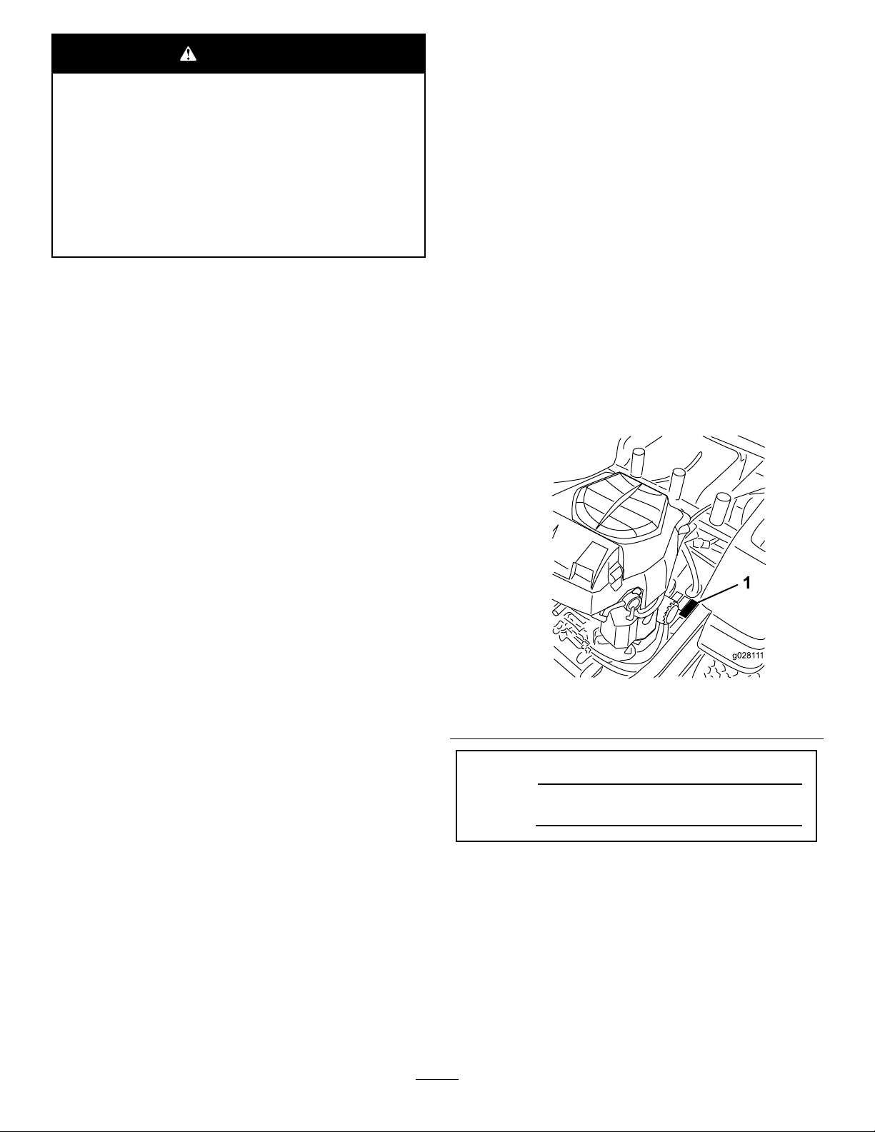
yourproductready.Figure1identiesthelocationofthe
modelandserialnumbersontheproduct.Writethenumbers
inthespaceprovided.
Formodelswithstatedenginehorsepower,thegross
horsepoweroftheenginewaslaboratorytestedbytheengine
manufacturerinaccordancewithSAEJ1995andratedto
J2723.
Figure1
1.Modelandserial-numberlocation
ModelNo.
SerialNo.
©2015—TheToro®Company
8111LyndaleAvenueSouth
Bloomington,MN55420
Contactusatwww.Toro.com.
2
PrintedintheUSA
AllRightsReserved
Page 3

Thismanualidentiespotentialhazardsandhassafety
messagesidentiedbythesafety-alertsymbol(Figure2),
whichsignalsahazardthatmaycauseseriousinjuryordeath
ifyoudonotfollowtherecommendedprecautions.
Figure2
1.Safety-alertsymbol
Thismanualuses2wordstohighlightinformation.
Importantcallsattentiontospecialmechanicalinformation
andNoteemphasizesgeneralinformationworthyofspecial
attention.
Contents
Safety...........................................................................4
SafeOperatingPractices...........................................4
SlopeIndicator.......................................................7
SafetyandInstructionalDecals.................................8
ProductOverview.........................................................13
Controls...............................................................13
Operation....................................................................15
AddingFuel...........................................................15
ThinkSafetyFirst...................................................16
UsingtheRolloverProtectionSystem(ROPS)............17
UnderstandingtheSafety-InterlockSystem................17
TestingtheSafety-InterlockSystem...........................17
CheckingtheEngine-OilLevel.................................18
BreakinginaNewMachine......................................18
OperatingtheParkingBrake....................................18
OperatingtheThrottle............................................18
OperatingtheChoke...............................................18
OperatingtheIgnitionSwitch..................................19
StartingandStoppingtheEngine..............................19
OperatingtheBlade-ControlSwitch(PTO)................20
DrivingtheMachine...............................................20
StoppingtheMachine.............................................22
AdjustingtheHeightofCut.....................................22
AdjustingtheAnti-ScalpRollers...............................23
PositioningtheSeat................................................23
ChangingtheSeatSuspension..................................23
AdjustingtheMotion-ControlLevers........................24
PushingtheMachinebyHand..................................24
UsingtheSideDischarge.........................................25
TransportingtheMachine........................................25
LoadingtheMachine..............................................25
OperatingTips......................................................27
Maintenance.................................................................28
RecommendedMaintenanceSchedule(s)......................28
PremaintenanceProcedures........................................29
Service-IntervalChart.............................................29
RaisingtheSeat......................................................29
Lubrication...............................................................29
GreasingtheBearings.............................................29
EngineMaintenance..................................................30
ServicingtheAirCleaner.........................................30
ServicingtheEngineOil..........................................31
ServicingtheSparkPlug..........................................33
CleaningtheBlowerHousing...................................34
FuelSystemMaintenance...........................................34
ReplacingtheFuelFilter..........................................34
ElectricalSystemMaintenance....................................35
ServicingtheBattery...............................................35
ServicingtheFuses.................................................36
DriveSystemMaintenance.........................................37
CheckingtheTirePressure......................................37
HydraulicSystemMaintenance....................................38
CheckingtheHydraulic-FluidLevel..........................38
ChangingtheHydraulicFilterandFluid.....................38
MowerDeckMaintenance...........................................40
ServicingtheCuttingBlades.....................................40
3
Page 4

LevelingtheMowerDeck........................................42
InspectingtheBelts................................................44
ReplacingtheMowerBelt........................................44
RemovingtheMower..............................................45
InstallingtheMowerDeck.......................................46
ReplacingtheGrassDeector..................................46
Cleaning...................................................................47
WashingtheUndersideoftheMower........................47
DisposingofWaste.................................................48
Storage........................................................................48
CleaningandStorage..............................................48
Troubleshooting...........................................................50
Schematics...................................................................52
Safety
Improperlyusingormaintainingthemachinecanresult
ininjury.Toreducethepotentialforinjury,complywith
thesesafetyinstructionsandalwayspayattentiontothe
safetyalertsymbol,whichmeansCaution,Warning,or
Danger—personalsafetyinstruction.Failuretocomply
withtheinstructionmayresultinpersonalinjuryor
death.
Thisproductiscapableofamputatinghandsandfeetand
throwingobjects.Alwaysfollowallsafetyinstructionsto
avoidseriousinjuryordeath.
Thisproductisdesignedforcuttingandrecyclinggrassor,
whenequippedwithagrassbagger,forcatchingcutgrass.
Anyuseforpurposesotherthanthesecouldprovedangerous
touserandbystanders.
SafeOperatingPractices
ThefollowinginstructionsareadaptedfromANSIstandard
B71.4-2012.
Training
•ReadtheOperator'sManualandothertrainingmaterial.If
theoperator(s)ormechanic(s)cannotreadEnglishitis
theowner'sresponsibilitytoexplainthismaterialtothem.
•Becomefamiliarwiththesafeoperationoftheequipment,
operatorcontrols,andsafetysigns.
•Alloperatorsandmechanicsshouldbetrained.The
ownerisresponsiblefortrainingtheusers.
•Neverletchildrenoruntrainedpeopleoperateorservice
theequipment.Localregulationsmayrestricttheageof
theoperator.
•Theowner/usercanpreventandisresponsiblefor
accidentsorinjuriesoccurringtopeopleordamageto
property.
Preparation
•Evaluatetheterraintodeterminewhataccessoriesand
attachmentsareneededtoproperlyandsafelyperform
thejob.Useonlyaccessoriesandattachmentsapproved
bythemanufacturer.
•Wearappropriateclothingincludingsubstantial
slip-resistantfootwear,ahardhat,eyeprotection,and
hearingprotection.Tiebacklonghair.Donotwear
jewelry.
•Inspecttheareawheretheequipmentistobeusedand
removeallobjectssuchasrocks,toysandwirewhichcan
bethrownbythemachine.
•Checkthatoperator-presencecontrols,safetyswitches
andshieldsareattachedandfunctioningproperly.Donot
operatethemachineunlesstheyarefunctioningproperly.
4
Page 5

Operation
Rollover-ProtectionSystem(ROPS)
•Lightningcancausesevereinjuryordeath.Iflightning
isseenorthunderisheardinthearea,donotoperate
themachine;seekshelter.
•Neverrunanengineinanenclosedarea.
•Onlyoperateingoodlight,keepingawayfromholesand
hiddenhazards.
•EnsurethatalldrivesareinNEUTRALandthatthe
parkingbrakeisengagedbeforestartingengine.Startthe
engineonlyfromtheoperator'sposition.
•Slowdownanduseextracareonhillsides.Besureto
travelsidetosideonhillsides.Turfconditionscanaffect
themachine'sstability.Usecautionwhileoperatingnear
drop-offs.
•Slowdownandusecautionwhenmakingturnsandwhen
changingdirectionsonslopes.
•Neverraisethedeckwiththebladesrunning.
•NeveroperatewiththePTOshield,orotherguardsnot
securelyinplace.Ensurethatallinterlocksareattached,
adjustedproperly ,andfunctioningproperly .
•Neveroperatewiththedischargedeectorraised,
removedoraltered,unlessusingagrasscatcher.
•Donotchangetheenginegovernorsettingoroverspeed
theengine.
•Stoponlevelground,disengagethedrives,engagethe
parkingbrake(ifprovided),shutofftheenginebefore
leavingtheoperator'spositionforanyreasonincluding
emptyingthecatchersoruncloggingthechute.
•Stopequipmentandinspectbladesafterstrikingobjects
orifanabnormalvibrationoccurs.Makenecessary
repairsbeforeresumingoperations.
•Keephandsandfeetawayfromthecuttingunit.
•Lookbehindanddownbeforebackinguptobesureof
aclearpath.
•Keeppetsandbystandersaway .
•Slowdownandusecautionwhenmakingturnsand
crossingroadsandsidewalks.Stopthebladesifyouare
notmowing.
•Beawareofthemowerdischargedirectionanddonot
pointitatanyone.
•Donotoperatethemowerwhileill,tired,orunderthe
inuenceofalcoholordrugs.
•Usecarewhenloadingorunloadingthemachineinto
orfromatrailerortruck.
•Usecarewhenapproachingblindcorners,shrubs,trees,
orotherobjectsthatmayobscurevision.
•DonotremovetheROPS.
•TheROPSisanintegralandeffectivesafetydevice.Keep
theROPSonthemachineandusetheseatbeltwhen
operatingthemachine.
•Becertainthattheseatbeltcanbereleasedquicklyin
theeventofanemergency.
•Checktheareatobemowedwherethereareslopes,
dropoffs,orwater.
•Carefullycheckforoverheadclearances(i.e.,branches,
doorways,electricalwires)beforedrivingunderany
objectsanddonotcontactthem.
•KeeptheROPSinsafeoperatingconditionby
periodicallythoroughlyinspectingfordamageand
keepingallmountingfastenerstight.
•ReplaceadamagedROPS.Donotrepairorrevise.
•AnyalterationstoaROPSmustbeapprovedbythe
manufacturer.
SafeHandlingofFuel
•Toavoidpersonalinjuryorpropertydamage,use
extremecareinhandlinggasoline.Gasolineisextremely
ammableandthevaporsareexplosive.
•Extinguishallcigarettes,cigars,pipes,andothersources
ofignition.
•Useonlyanapprovedfuelcontainer.
•Neverremovefuelcaporaddfuelwiththeengine
running.
•Allowenginetocoolbeforerefueling.
•Neverrefuelthemachineindoors.
•Neverstorethemachineorfuelcontainerwherethereis
anopename,spark,orpilotlightsuchasonawater
heateroronotherappliances.
•Neverllcontainersinsideavehicleoronatruckor
trailerbedwithaplasticliner.Alwaysplacecontainerson
thegroundawayfromyourvehiclebeforelling.
•Removeequipmentfromthetruckortrailerandfuelit
ontheground.Ifthisisnotpossible,thenrefuelsuch
equipmentwithaportablecontainerratherthanfroma
fueldispensernozzle.
•Keepthenozzleincontactwiththerimofthefueltank
orcontaineropeningatalltimesuntilfuelingiscomplete.
Donotuseanozzlelockopendevice.
•Iffuelisspilledonclothing,changeclothingimmediately.
•Neveroverllthefueltank.Replacethefuelcapand
tightenitsecurely.
5
Page 6

MaintenanceandStorage
•Disengagedrives,setparkingbrake,stopengineand
removekeyordisconnectspark-plugwire.Waitforall
movementtostopbeforeadjusting,cleaningorrepairing.
•Cleangrassanddebrisfromcuttingunit,drives,mufers,
andenginetohelppreventres.Cleanupoilorfuel
spillage.
•Lettheenginecoolbeforestoringanddonotstorenear
ame.
•Shutoffthefuelwhilestoringortransporting.Donot
storefuelnearamesordrainindoors.
•Parkthemachineonlevelground.Settheparkingbrake.
Neverallowuntrainedpersonneltoservicethemachine.
•Usejackstandstosupportcomponentswhenrequired.
•Carefullyreleasepressurefromcomponentswithstored
energy.
•Disconnectthebatteryorremovespark-plugwirebefore
makinganyrepairs.Disconnectthenegativeterminalrst
andthepositivelast.Reconnectthepositiverstand
negativelast.
•Usecarewhencheckingblades.Wraptheblade(s)orwear
thickly-paddedgloves,andusecautionwhenservicing
them.Onlyreplaceblades.Neverstraightenorweld
them.
•Keephandsandfeetawayfrommovingparts.Ifpossible,
donotmakeadjustmentswiththeenginerunning.
•Keepallpartsingoodworkingconditionandallhardware
tightened.Replaceallwornordamageddecals.
Hauling
•Usecarewhenloadingorunloadingthemachineintoa
trailerortruck.
•Usefullwidthrampsforloadingmachineintotraileror
truck.Therampangleshouldnotexceed15degrees.
•Tiethemachinedownsecurelyusingstraps,chains,cable,
orropes.Bothfrontandrearstrapsshouldbedirected
downandoutwardfromthemachine.
6
Page 7
SlopeIndicator
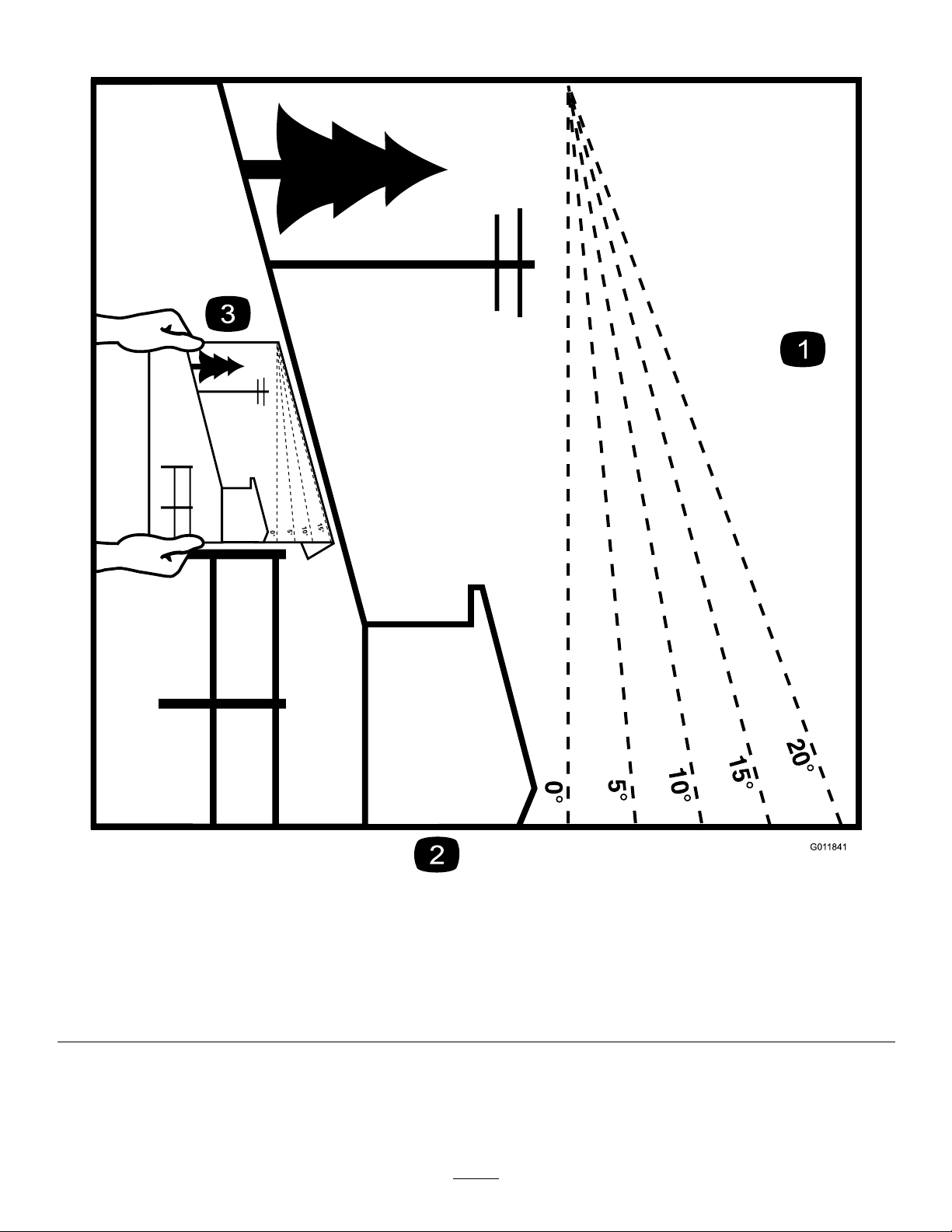
G011841
Figure3
Thispagemaybecopiedforpersonaluse.
1.Themaximumslopeyoucansafelyoperatethemachineonis15degrees.Usetheslopecharttodeterminethedegreeofslope
ofhillsbeforeoperating.Donotoperatethismachineonaslopegreaterthan15degrees.Foldalongtheappropriateline
tomatchtherecommendedslope.
2.Alignthisedgewithaverticalsurface,atree,building,fencepole,etc.
3.Exampleofhowtocompareslopewithfoldededge.
7
Page 8
SafetyandInstructionalDecals
Safetydecalsandinstructionsareeasilyvisibletotheoperatorandarelocatednearanyareaofpotential
danger.Replaceanydecalthatisdamagedorlost.
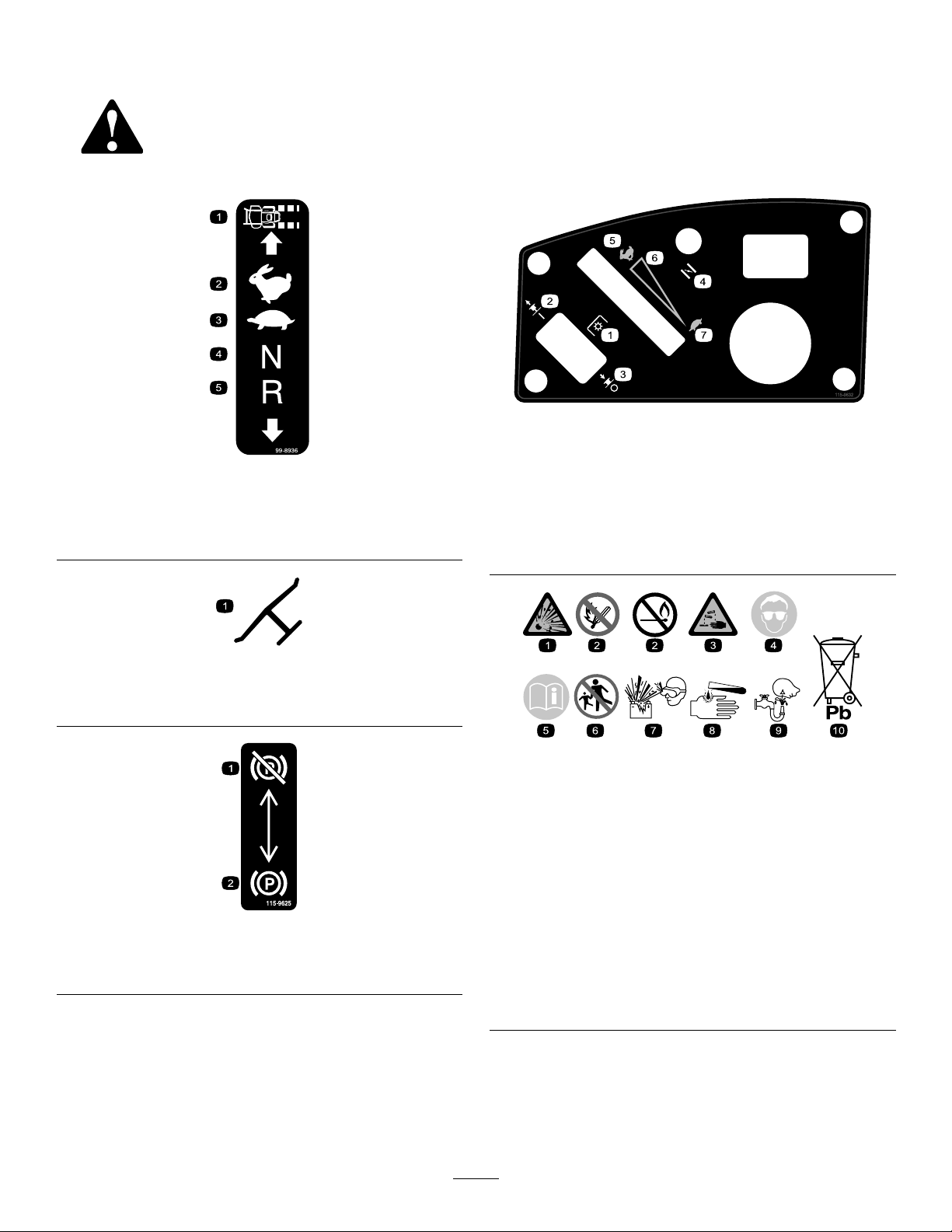
115-9632
99-8936
1.Machinespeed4.Neutral
2.Fast5.Reverse
3.Slow
Manufacturer'sMark
1.Indicatesthebladeisidentiedasapartfromtheoriginal
machinemanufacturer.
115-9625
1.Parking
brake—disengaged
2.Parkingbrake—engaged
1.Powertake-off(PTO),
Bladecontrolswitchon
somemodels
2.Bladecontrolswitch—On6.Continuousvariable
3.Bladecontrolswitch—Off7.Slow
4.Choke
5.Fast
setting
BatterySymbols
Someorallofthesesymbolsareonyourbattery
1.Explosionhazard
2.Nore,opename,or
smoking.
3.Causticliquid/chemical
burnhazard
4.Weareyeprotection9.Flusheyesimmediately
5.ReadtheOperator's
Manual.
6.Keepbystandersasafe
distancefromthebattery.
7.Weareyeprotection;
explosivegasescan
causeblindnessandother
injuries
8.Batteryacidcancause
blindnessorsevereburns.
withwaterandgetmedical
helpfast.
10.Containslead;donot
discard.
8
Page 9
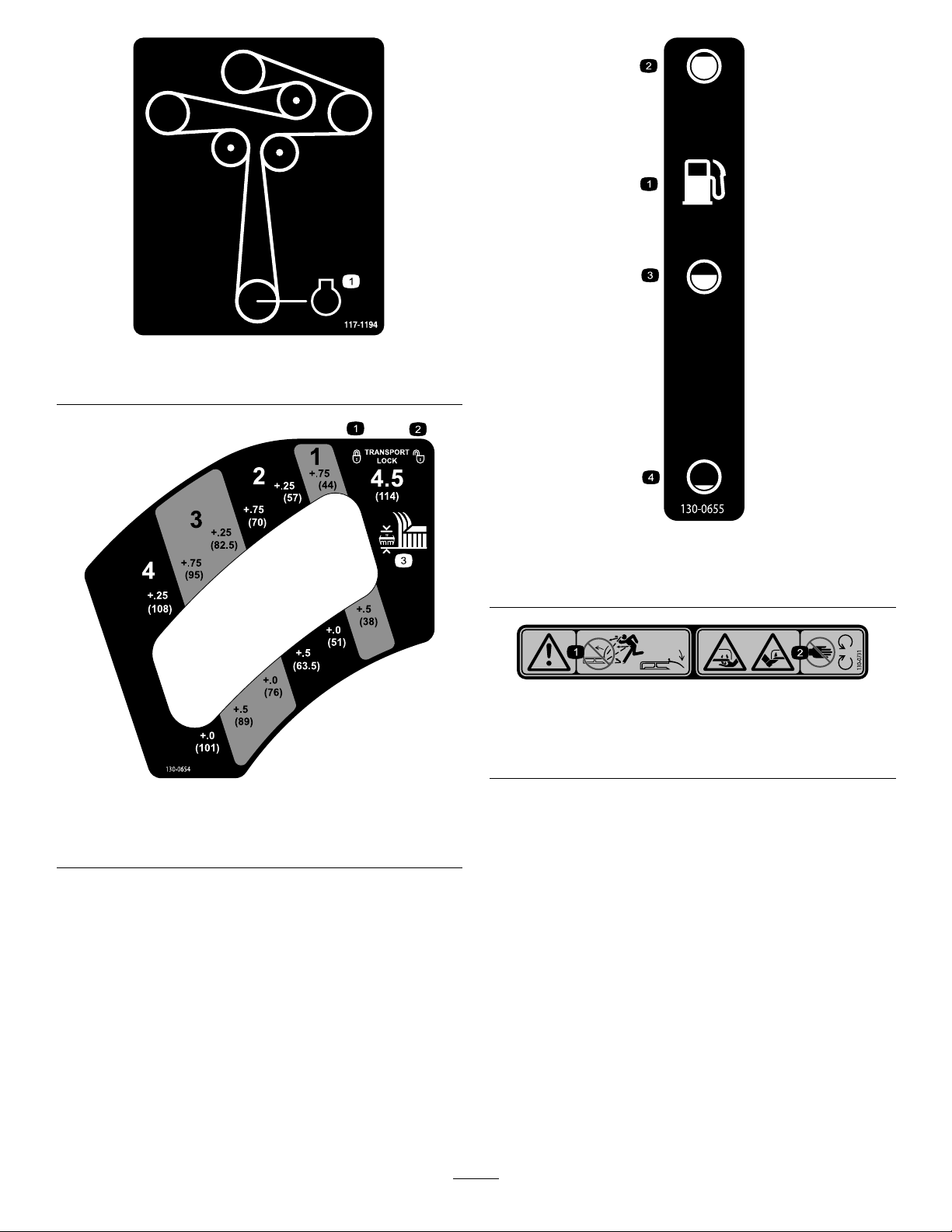
117-1194
1.Engine
130-0655
1.Fueltank
2.Full4.Empty
3.Half
130-0731
1.Warning—thrownobject
hazard;keepthedeector
shieldinplace.
2.Cuttinghazardofhandor
foot,mowerblade—keep
awayfrommovingparts.
130-0654
1.Transport—lock
2.Transport—unlock
3.Height-of-cut
9
Page 10
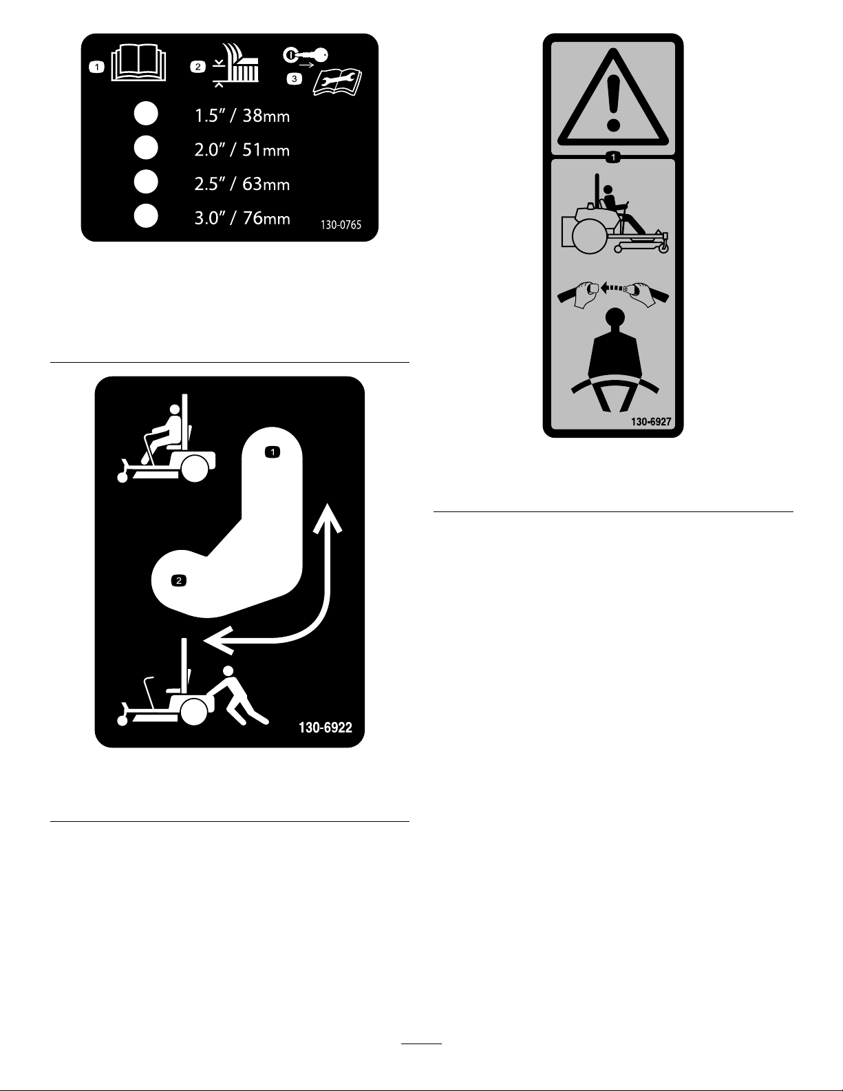
130-0765
1.ReadtheOperator's
Manual.
2.Height-of-cutselection
3.Removethekeyfrom
theignitionandreadthe
Operator'sManualbefore
performingmaintenance.
130-6927
1.Warning—alwaysusetheROPSandweartheseatbelt
whenseatedintheoperator'sposition.
1.Bypassleverpositionfor
operatingthemachine.
130-6922
2.Bypassleverpositionfor
pushingthemachine.
10
Page 11
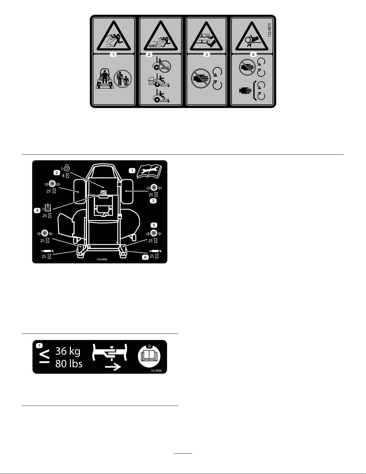
132-0873
1.Thrownobjecthazard—keepbystandersawayfromthe
machine.
2.Thrownobjecthazard,mower—donotoperatethewithout
deector,dischargecover,orgrasscollectionsysteminplace.
130-6996
1.ReadtheOperator's
Manualforinformationon
maintenance.
2.Checktheengineoilevery
8hours.
3.Checkthedrivewheeltire
pressureevery25hours.
4.Checkthehydraulicuid
every25hours.
5.Checkthecasterwheel
tirepressureevery25
hours.
6.Lubricatethecasterwheel
every25hours.
3.Cutting/dismembermentofhandorfoot—stayawayfrom
movingparts.
4.Entanglementhazard,belt—keepallguardsinplace.
1.Maximumdrawbarpull80
lbs(36kg)
131-4036
2.ReadtheOperator's
Manual.
11
Page 12

132–0871
1.Warning—readtheOperator’sManual;donotoperatethis
vehicleunlessyouaretrained;wearhearingprotection.
2.Cuttingandpinchinghazard—keephandsandfeetawayfrom
movingparts;keepallguardsandshieldsinplace.
3.Thrownobjecthazard—keepbystandersaway .6.Tippinghazardonslopes—donotuseonslopesnearopen
4.Ramphazard—whenloadingontoatrailer,donotusedual
ramps;onlyuseasingularrampwideenoughforthemachine;
backuptheramp(inreverse)anddriveforwardofftheramp.
5.Bodilyharmhazard—lookbehindyouwhenmowingin
reverse.
water;donotuseonslopesgreaterthan15degrees.
12
Page 13

ProductOverview
Figure4
1.Drivewheel4.Motion-controllevers7.Frontcasterwheel
2.Operatorseat
3.RolloverProtectionSystem
(ROPS)
5.Parkingbrake8.Anti-scalproller
6.Footrest
9.Footpedaldeckliftand
heightofcut
Controls
Becomefamiliarwithallthecontrolsbeforeyoustartthe
engineandoperatethemachine(Figure5).
10.Deector
Figure5
1.Throttlecontrol4.Ignitionswitch
2.Choke
3.Hourmeter
13
5.Blade-controlswitch
(PTO)
Page 14
IgnitionSwitch
g020264
1
Motion-ControlLevers
Theignitionswitchhas3positions:START,RUN,andOFF..
ThekeywillturntotheSTARTpositionandmovebackto
theRUNpositionuponrelease.TurningthekeytotheOFF
positionshutsofftheengine;however,alwaysremovethe
keywhenleavingthemachinetopreventtheenginefrom
accidentallystarting(Figure5).
ThrottleControl
ThethrottlecontrolisvariablebetweentheFASTandSLOW
position.Movingthrottleleverforwardincreasesengine
speedandmovingthrottlelevertothereardecreasesengine
speed.Movingthethrottleforwardintothedetentisfull
throttle(Figure5).
Choke
Usethechoketostartacoldengine.Pullthechokeknobup
toengageit.Pushdownonthechokeknobtodisengageit.
Blade-ControlSwitch(PowerTakeoff)
Theblade-controlswitchengagesanddisengagespowerto
themowerblades(Figure5).
Themotion-controlleversarespeed-sensitivecontrolsof
independent-wheelmotors.Movingaleverforwardor
backwardturnsthewheelonthesamesideforwardor
inreverse;wheelspeedisproportionaltotheamountthe
leverismoved.Movethecontrolleversoutwardfromthe
centertotheNEUTRAL-LOCKpositionandexitthemachine
(Figure4).Alwayspositionthemotion-controlleversinto
theNEUTRAL-LOCKpositionwhenyoustopthemachine
orleaveitunattended.
Parking-BrakeLever
Theparking-brakeleverislocatedonleftsideoftheconsole
(Figure4).Thebrakeleverengagesaparkingbrakeonthe
drivewheels.Pulltheleverupandrearwardtoengagethe
brake.Pushtheleverforwardanddowntodisengagethe
brake.
FootPedalDeck-LiftSystem
Thefootpedaldeck-liftsystemallowstheoperatortolower
andraisethedeckfromtheseatedposition.Youcanusethe
footpedaltoliftthedeckbrieytoavoidobstaclesorlock
thedeckinthehighestheightofcutortransportposition
(Figure4).
HourMeter
Thehourmeterrecordsthenumberofhourstheblades
operate.Itoperateswhentheblade-controlswitch(PTO)is
engaged.Usethesetimesforschedulingregularmaintenance
(Figure5).
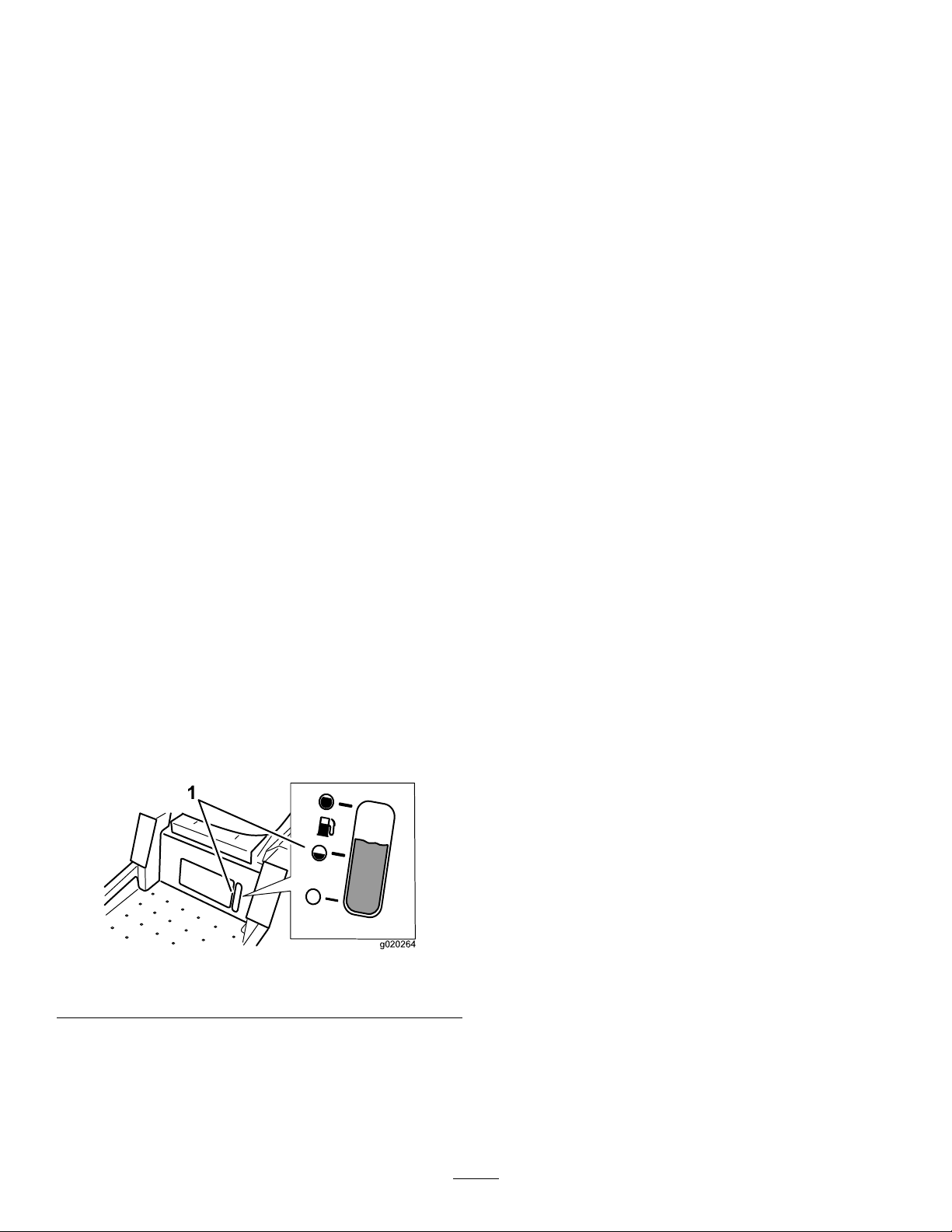
FuelGauge
Thefuelwindowlocatedbelowtheoperatorpositioncanbe
usedtoverifythelevelofgasolineinthetank(Figure6).
Figure6
1.Fuel-gaugewindow
Height-of-CutLever
Theheight-of-cutleverworkswiththefootpedaltolockthe
deckinaspeciccuttingheight.Onlyadjusttheheightofcut
whilemachineisnotmoving(Figure4).
Attachments/Accessories
AselectionofToroapprovedattachmentsandaccessoriesis
availableforusewiththemachinetoenhanceandexpand
itscapabilities.ContactyourAuthorizedServiceDealeror
Distributororgotowww .Toro.comforalistofallapproved
attachmentsandaccessories.
14
Page 15

Operation
Note:Determinetheleftandrightsidesofthemachine
fromthenormaloperatingposition.
AddingFuel
•Forbestresults,useonlyclean,fresh,unleadedgasoline
withanoctaneratingof87orhigher((R+M)/2rating
method).
•Oxygenatedfuelwithupto10%ethanolor15%MTBE
byvolumeisacceptable.
•Donotuseethanolblendsofgasoline(suchasE15
orE85)withmorethan10%ethanolbyvolume.
Performanceproblemsand/orenginedamagemayresult
whichmaynotbecoveredunderwarranty.
•Donotusegasolinecontainingmethanol.
•Donotstorefueleitherinthefueltankorfuelcontainers
overthewinterunlessafuelstabilizerisused.
•Donotaddoiltogasoline.
DANGER
Incertainconditionsduringfueling,static
electricitycanbereleasedcausingasparkwhich
canignitethegasolinevapors.Areorexplosion
fromgasolinecanburnyouandothersandcan
damageproperty.
•Alwaysplacegasolinecontainersontheground
awayfromyourvehiclebeforelling .
•Donotllgasolinecontainersinsideavehicleor
onatruckortrailerbedbecauseinteriorcarpets
orplastictruckbedlinersmayinsulatethe
containerandslowthelossofanystaticcharge.
WARNING
Gasolineisharmfulorfatalifswallowed.Long-term
exposuretovaporscancauseseriousinjuryand
illness.
•Avoidprolongedbreathingofvapors.
•Keepfaceawayfromnozzleandgastankor
conditioneropening.
•Keepgasawayfromeyesandskin.
DANGER
Incertainconditions,gasolineisextremely
ammableandhighlyexplosive.Areorexplosion
fromgasolinecanburnyouandothersandcan
damageproperty.
•Fillthefueltankoutdoors,inanopenarea,
whentheengineiscold.Wipeupanygasoline
thatspills.
•Neverllthefueltankinsideanenclosedtrailer.
•Donotllthefueltankcompletelyfull.Add
gasolinetothefueltankuntilthelevelis6to13
mm(1/4to1/2inch)belowthebottomofthe
llerneck.Thisemptyspaceinthetankallows
gasolinetoexpand.
•Neversmokewhenhandlinggasoline,andstay
awayfromanopenameorwheregasoline
fumesmaybeignitedbyaspark.
•Storegasolineinanapprovedcontainerand
keepitoutofthereachofchildren.Neverbuy
morethana30-daysupplyofgasoline.
•Donotoperatewithoutentireexhaustsystemin
placeandinproperworkingcondition.
•Whenpractical,removegas-poweredequipment
fromthetruckortrailerandrefueltheequipment
withitswheelsontheground.
•Ifthisisnotpossible,thenrefuelsuch
equipmentonatruckortrailerfromaportable
container,ratherthanfromagasolinedispenser
nozzle.
•Ifyoumustagasoline-dispensernozzle,keep
thenozzleincontactwiththerimofthefuel
tankorcontaineropeningatalltimesuntil
fuelingiscomplete.
UsingStabilizer/Conditioner
Useafuelstabilizer/conditionerinthemachinetoprovide
thefollowingbenets:
•Keepsgasolinefreshduringstorageof90daysorless.
Forlongerstorageitisrecommendedthatthefueltank
bedrained.
•Cleanstheenginewhileitruns
•Eliminatesgum-likevarnishbuildupinthefuelsystem,
whichcauseshardstarting
Important:Donotusefueladditivescontaining
methanolorethanol.
Addthecorrectamountofgasstabilizer/conditionertothe
gas.
Note:Afuelstabilizer/conditionerismosteffectivewhen
mixedwithfreshgasoline.Tominimizethechanceofvarnish
depositsinthefuelsystem,usefuelstabilizeratalltimes.
15
Page 16
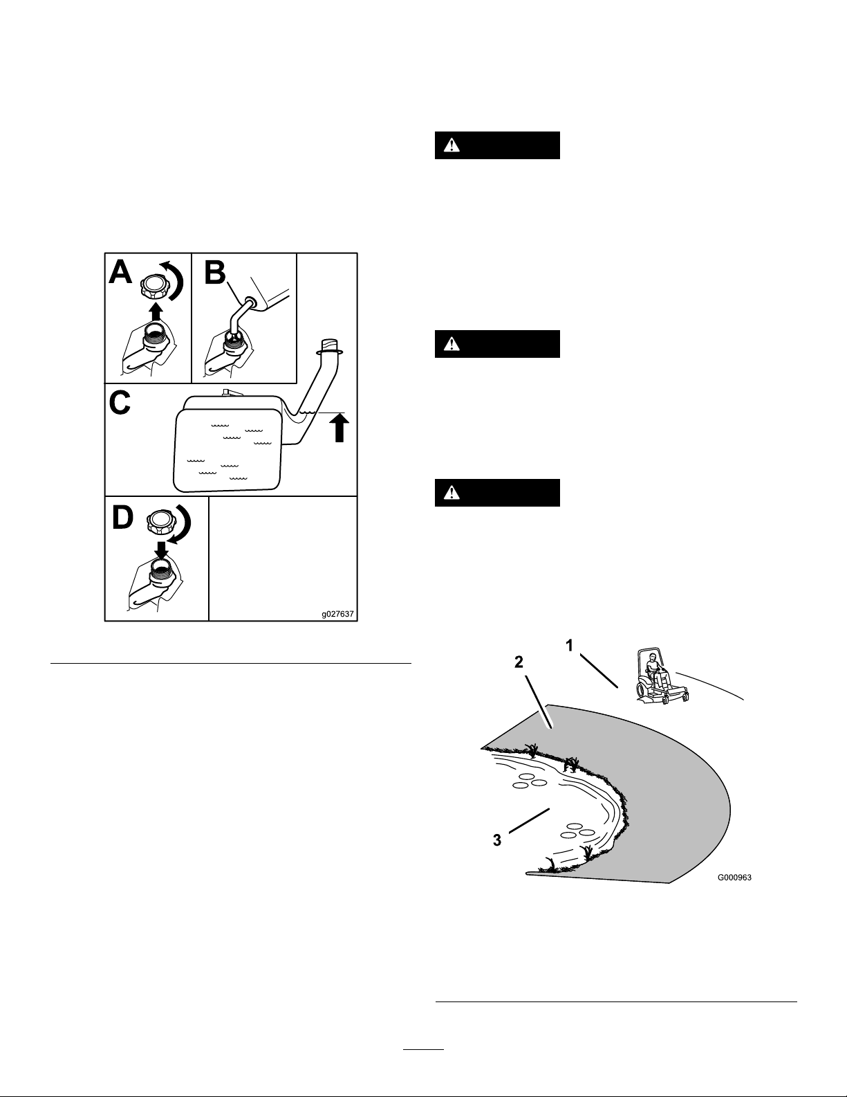
FillingtheFuelTank
B
A
C
D
g027637
Shutofftheengineandmovethemotioncontrolstothe
PARKposition.
Important:Donotoverllfueltank.Fillthefueltank
tothebottomofthellerneck.Theemptyspaceinthe
tankallowsthefueltoexpand.Overllingmayresultin
fuelleakageordamagetotheengineoremissionsystem.
1.Cleanaroundthefuel-tankcapandremovethecap.
ThinkSafetyFirst
Pleasereadallsafetyinstructionsandsymbolsinthesafety
section.Knowingthisinformationcouldhelpyouor
bystandersavoidinjury.
DANGER
Operatingthemachineonwetgrassorsteepslopes
cancauseslidingandlossofcontrol.
2.Slowlyaddregular,unleadedgasolineuntilthefuel
reachesthebaseofthellerneckFigure7.
•Donotoperateonslopesgreaterthan15degrees.
•Reducespeedanduseextremecautionon
slopes.
•Donotoperatethemachinenearwater.
DANGER
Wheelsdroppingoveredgescancauserollovers,
whichmayresultinseriousinjury,death,or
drowning.
Donotoperatethemachineneardrop-offs.
DANGER
Operatingthemachinewhiletherollbarisdown
mayleadtoseriousinjuryordeathintheeventofa
rollover.
Alwayskeeptherollbarinthefullyraisedand
lockedpositionandusetheseatbelt.
Figure7
3.Installthefuel-tankcapsecurelyandtightenuntilit
clicks.
Note:Wipeupanygasolinethatmayhavespilled.
1.Safezone—usethe
machinehere.
2.Useawalk-behindmower
and/orhandtrimmernear
drop-offsandwater.
Figure8
3.Water
16
Page 17
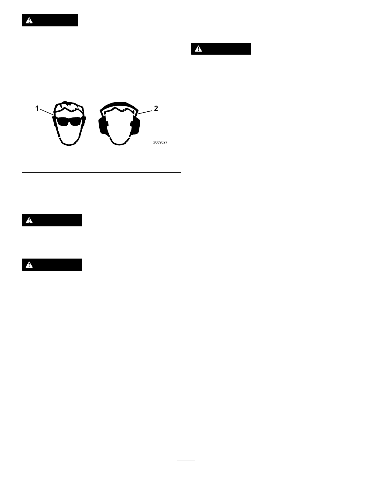
CAUTION
G009027
1
2
Understandingthe
Thismachineproducessoundlevelsinexcessof
85dBAattheoperatorsearandcancausehearing
lossthroughextendedperiodsofexposure.
Wearhearingprotectionwhenoperatingthis
machine.
Wearprotectiveequipmentforyoureyes,ears,hands,andfeet
whenusingthismachine(Figure9).
Figure9
1.Weareyeprotection.2.Wearhearingprotection.
UsingtheRolloverProtection System(ROPS)
Safety-InterlockSystem
WARNING
Ifthesafety-interlockswitchesaredisconnectedor
damaged,themachinecouldoperateunexpectedly,
causingpersonalinjury.
•Donottamperwiththeinterlockswitches.
•Checktheoperationoftheinterlockswitches
dailyandreplaceanydamagedswitchesbefore
operatingthemachine.
Thesafety-interlocksystemisdesignedtopreventtheengine
fromstartingunless:
•Thebladesaredisengaged.
•Themotion-controlleversareinthePARKposition.
Thesafety-interlocksystemalsoisdesignedtoshutoffthe
enginewheneverthecontrolleversareoutofthePARK
positionandyourisefromtheseat.
TestingtheSafety-Interlock
WARNING
Toavoidinjuryordeathfromrollover:keeptheroll
barinstalledandusetheseatbelt.
WARNING
Thereisnorolloverprotectionwhentherollbaris
removed.
•Driveslowlyandcarefully.
•Checkcarefullyforoverheadclearances(i.e.
branches,doorways,electricalwires)before
drivingunderanyobjectsanddonotcontact
them.
System
Testthesafety-interlocksystembeforeyouusethemachine
eachtime.Ifthesafetysystemdoesnotoperateasdescribed
below,haveanAuthorizedServiceDealerrepairthesafety
systemimmediately.
1.Whilesittingontheseat,withthecontrolleversinthe
PARKposition,andmovetheblade-controlswitchto
theONposition.Trystartingtheengine;theengine
shouldnotstart.
2.Whilesittingontheseat,movetheblade-controlswitch
totheOFFposition.Moveeithermotioncontrol
levertothecenter,unlockedposition.Trystartingthe
engine;theengineshouldnotstart.Repeatwiththe
othermotion-controllever.
3.Whilesittingontheseat,movethebladecontrolswitch
totheOFFposition,andlockthemotion-controllevers
inthePARKposition.Starttheengine.Whilethe
engineisrunning,engagetheblade-controlswitch,and
riseslightlyfromtheseat;theengineshouldshutoff.
4.Whilesittingontheseat,movetheblade-controlswitch
totheOFFposition,andlockthemotion-controllevers
inthePARKposition.Starttheengine.Whilethe
engineisrunning,movethemotion-controlleversto
thecenter,unlockedposition,engagetheblade-control
switch,andriseslightlyfromtheseat;theengine
shouldshutoff.
17
Page 18

CheckingtheEngine-OilLevel
B
A
g027638
B
A
g027639
g028222
G008959
1
2
OperatingtheThrottle
Beforeyoustarttheengineandusethemachine,check
theoillevelintheenginecrankcase;refertoCheckingthe
Engine-OilLevel(page31).
BreakinginaNewMachine
Newenginestaketimetodevelopfullpower.Mowerdecks
anddrivesystemshavehigherfrictionwhennew,placing
additionalloadontheengine.Allow40to50hoursof
break-intimefornewmachinestodevelopfullpowerand
bestperformance.
OperatingtheParkingBrake
Alwayssettheparkingbrakewhenyoustopthemachineor
leaveitunattended.
SettingtheParkingBrake
ThethrottlecontrolcanbemovedbetweentheSLOWand
FASTpositions(Figure12).
AlwaysusetheFASTpositionwhenturningonthemower
deckwiththeblade-controlswitch(PTO).
Figure12
OperatingtheChoke
Usethechoketostartacoldengine.
1.Iftheengineiscold,usethechoketostarttheengine.
2.Pulluponthechokeknobtoengagethechokebefore
usingtheignitionswitch(Figure13).
3.Pushdownonthechoketodisengagethechokeafter
theenginestarts(Figure13).
ReleasingtheParkingBrake
Figure10
Figure11
Figure13
1.ONposition2.OFFposition
18
Page 19

OperatingtheIgnitionSwitch
START
RUN
STOP
G008947
g028223
B
A
D
C
F
E
S
T
A
R
T
R
U
N
S
T
O
P
H
G
1.TurntheignitionkeytotheSTARTposition(Figure14).
Note:Whentheenginesstarts,releasethekey.
Note:Additionalstartingcyclesmayberequired
whenstartingtheengineforthersttimeafterthefuel
systemhasbeenwithoutfuelcompletely.
Figure14
2.TurntheignitionkeytotheSTOPposition.
StartingandStoppingthe Engine
StartingtheEngine
StarttheengineasshowninFigure15.
Note:Awarmorhotenginemaynotrequirechoking.
Important:Donotengagestarterformorethan5
secondsatatime.Iftheenginefailstostartallowa15
secondcool-downperiodbetweenattempts.Failureto
followtheseinstructionscanburnoutthestartermotor.
Note:Ifthefuelsystemwasdepletedoffuel—addfuelto
themachineanduseadditionalstartingcycleswhenstarting
theengine.
Figure15
StoppingtheEngine
CAUTION
Injurycanoccurifchildrenorbystandersmove
orattempttooperatethemachinewhileitis
unattended.
Alwaysremovetheignitionkeyandsettheparking
brakewhenleavingthemachineunattended,even
ifjustforafewminutes.
StoptheengineasshowninFigure16.
19
Page 20

BA
DC
E
S
T
A
R
T
R
U
N
S
T
O
P
g028224
Figure16
G008945
G009174
DisengagingtheBlade-ControlSwitch
(PTO)
Figure18
DrivingtheMachine
Thethrottlecontrolregulatestheenginespeedasmeasured
inrpm(revolutionsperminute).Placethethrottlecontrolin
theFASTpositionforbestperformance.Alwaysoperatein
thefull-throttlepositionwhenmowing.
CAUTION
Machinecanspinveryrapidly.Operatormaylose
controlofmachineandcausepersonalinjuryor
damagetomachine.
•Usecautionwhenmakingturns.
OperatingtheBlade-Control Switch(PTO)
Theblade-controlswitch(PTO)startsandstopsthemower
bladesandanypoweredattachments.
EngagingtheBlade-ControlSwitch
(PTO)
Engagetheblade-controlswitch(PTO)withthethrottle
positionatFAST.
Note:Engagingtheblade-controlswitch(PTO)withthe
throttlepositionathalforlesswillcauseexcessivewearto
thedrivebelts.
•Slowthemachinedownbeforemakingsharp
turns.
UsingtheMotion-ControlLevers
Usethemotion-controlleversasshowninFigure19.
Figure17
20
Page 21

Figure19
G008952
G008953
Figure20
1.Motion-control
lever—NEUTRAL-LOCK
position
2.Center,unlockedposition5.Frontofthemachine
3.Forward
4.Backward
DrivingForward
Note:Theenginekillsifthetraction-controlleversare
movedwiththeparkingbrakeengaged.
1.Releasetheparkingbrake.
2.Movetheleverstothecenter,unlockedposition.
3.Tomoveforward,slowlypushthemotion-control
leversforward(Figure20).
DrivingBackward
Note:Alwaysusecautionwhenbackingupandturning.
1.Movetheleverstothecenter,unlockedposition.
2.Togobackward,slowlypullthemotion-controllevers
rearward(Figure21).
Figure21
21
Page 22

StoppingtheMachine
g024409
WARNING
Childrenorbystandersmaybeinjuredifthey
moveorattempttooperatethemachinewhileitis
unattended.
Alwaysremovetheignitionkeyandmovethe
motion-controlleversoutwardtothePARKposition
whenleavingthemachineunattended,evenifjust
forafewminutes.
Tostopthemachine,movethetraction-controlleversto
theNEUTRALpositionandmovetothelockedposition,
disengagetheblade-controlswitch(PTO),andturnthe
ignitionkeytotheOFFposition.
Settheparkingbrakewhenyouleavethemachine.Remember
toremovethekeyfromtheignitionswitch.
AdjustingtheHeightofCut
Themachineisequippedwithafootpedaldeck-liftsystem.
Theoperatorcanusethefootpedaltoliftthedeckbrieyto
avoidobstaclesorlockthedeckinthehighestheightofcut
ortransportposition.Theoperatorcanusetheheight-of-cut
leverwiththefootpedaltolockthedeckinaspeciccutting
height.
Figure22
TransportLockPosition
AdjustingtheHeightofCut
Theheightofcutcanbeadjustedfrom38to114mm(1-1/2
to4-1/2inches)in6mm(1/4inch)incrementsbyrelocating
theheight-of-cutpinintodifferentholelocations.
UsingtheFootPedalDeck-LiftSystem
•Pressthepedaldowntoraisethedeck;continuetopress
thepedaluntilthedeckislockedinthetransportposition
(Figure22).
•Pushonthedeck-liftpedalwithyourfootandpullthe
transportlockhandlerearwardtodisengagethetransport
lock(Figure22).
1.Pushonthedeck-liftpedalwithyourfootandraise
themowerdecktothetransport-lockposition(also
the114mm(4-1/2inches)cuttingheightposition)as
showninFigure23.
2.Toadjust,removethepinfromtheheight-of-cut
bracket(Figure23).
3.Selectaholeintheheight-of-cutsystemcorresponding
tothedesiredheightofcutandinsertthepin(Figure
23).
4.Pushonthedeck-liftpedalwithyourfootandpull
thehandlerearwardtodisengagethetransportlock
(Figure22).
5.Lowerthedeckslowlyuntilthelevermakescontact
withthepin.
22
Page 23

g024410
1
2
3
4
Figure23
g024312
1
2 3 4
5
1.Deck-liftpedal3.Height-of-cutpositions
2.Handle4.Pin
AdjustingtheAnti-Scalp
4.Aligntheboltandanti-scalprollerintheholeofthe
bracketthatmatchedtheclosestheight-of-cutposition
(Figure24).
5.Inserttheboltintothebracketholeandsecurethebolt
andanti-scalprollerwiththeangenut(Figure24).
PositioningtheSeat
Theseatcanmoveforwardandbackward(Figure25).
Positiontheseatwhereyouhavethebestcontrolofthe
machineandaremostcomfortable.
Rollers
Wheneveryouchangetheheightofcut,itisrecommendedto
adjusttheheightoftheanti-scalprollers.
1.Disengagetheblade-controlswitch(PTO),movethe
motion-controlleverstotheNEUTRAL-LOCKposition,
andsettheparkingbrake.
2.Shutofftheengine,removethekey,andwaitforall
movingpartstostopbeforeleavingtheoperating
position.
3.Removetheangenut,anti-scalproller,andboltfrom
thebracket(Figure24).
Note:Keeptheboltandanti-scalprollertogether
whenremoving.
Figure25
ChangingtheSeatSuspension
Theseatisadjustabletoprovideasmoothandcomfortable
ride.Positiontheseatwhereyouaremostcomfortable.
Toadjustit,turntheknobinfronteitherdirectiontoprovide
thebestcomfort(Figure26).
1.Flangenut4.Bushing
2.Spacer
3.Anti-scalproller
Figure24
5.Bolt
1.Seat-suspensionknob
Figure26
23
Page 24

AdjustingtheMotion-Control
g027252
B
A
BA
DC
g027642
Levers
AdjustingtheHeight
Note:Repeattheadjustmentfortheoppositecontrollever.
Themotion-controlleverscanbeadjustedhigherorlowerfor
maximumoperatorcomfort(Figure27).
Figure27
Note:Ensurethattheleftandrightbypassleversare
rearwardandlockedbeforemovingthemachine.
Figure28
6.Disengagetheparkingbrake.
AdjustingtheTilt
Themotion-controlleverscanbetiltedforwardorrearward
formaximumoperatorcomfort.
1.Loosentheupperboltholdingthecontrollevertothe
control-armshaft.
2.Loosenthelowerboltjustenoughtopivotthecontrol
leverforwardorrearward.
3.Tightenbothboltstosecurethecontrolinthenew
position.
4.Repeattheadjustmentfortheoppositecontrollever.
PushingtheMachinebyHand
Important:Alwayspushthemachinebyhand.Never
towthemachinebecausedamagemayoccur.
1.Parkthemachineonalevelsurfaceanddisengagethe
blade-controlswitch.
2.Engagetheparkingbrake.
3.Movethemotion-controlleversoutwardtothe
NEUTRAL-LOCKposition,shutofftheengine,remove
thekey ,andwaitforallmovingpartstostopbefore
leavingtheoperatingposition.
OperatingtheMachine
Movethebypassleverstothepositionforoperatingthe
machine(Figure28)toengagethewheelmotors.
4.Locatethebypassleversattherearofthemachine,on
theleftandrightsideoftheframe.
5.Movethebypassleversrearwardandthendowntolock
theminplacetodisengagethewheelmotors(Figure
28).
24
Page 25

UsingtheSideDischarge
g028043
TransportingtheMachine
Themowerhasahingedgrassdeectorthatdisperses
clippingstothesideanddowntowardtheturf.
DANGER
Withoutagrassdeector,dischargecover,or
completegrasscatcherassemblymountedin
place,youandothersareexposedtobladecontact
andthrowndebris.Contactwithrotatingmower
blade(s)andthrowndebriswillcauseinjuryor
death.
•Neverremovethegrassdeectorfromthemower
becausethegrassdeectorroutesmaterialdown
towardtheturf.Ifthegrassdeectorisever
damaged,replaceitimmediately .
•Neverputyourhandsorfeetunderthemower.
•Nevertrytoclearthedischargeareaormower
bladesunlessyoumovetheblade-controlswitch
(PTO)totheOFFposition,rotatetheignition
keytotheOFFposition,andremovethekey.
•Makesurethatthegrassdeectorisinthedown
position.
Useaheavy-dutytrailerortrucktotransportthemachine.
Ensurethatthetrailerortruckhasallnecessarybrakes,
lighting,andmarkingasrequiredbylaw .Pleasecarefullyread
allthesafetyinstructions.Knowingthisinformationcould
helpyou,yourfamily,pets,orbystandersavoidinjury.
WARNING
Drivingonthestreetorroadwaywithout
turnsignals,lights,reectivemarkings,ora
slow-moving-vehicleemblemisdangerousandcan
leadtoaccidents,causingpersonalinjury.
Donotdrivethemachineonapublicstreetor
roadway.
1.Ifyouareusingatrailer,connectittothetowing
vehicleandconnectthesafetychains.
2.Ifapplicable,connectthetrailerbrakes.
3.Loadthemachineontothetrailerortruck.
4.Shutofftheengine,removethekey,setthebrake,and
closethefuelvalve.
5.Tiedownthemachinenearthefrontcasterwheelsand
therearbumper(Figure29).
Figure29
LoadingtheMachine
Useextremecautionwhenloadingorunloadingmachines
ontoatraileroratruck.Useafull-widthrampthatiswider
thanthemachineforthisprocedure.Backthemachineupthe
rampanddriveitforwarddowntheramp(Figure30).
Figure30
1.Backthemachineupthe
ramp.
2.Drivethemachineforward
downtheramp.
25
Page 26

Important:Donotusenarrowindividualrampsfor
g027996
5
1
2
6
eachsideofthemachine.
Ensuretherampislongenoughsothattheanglewiththe
grounddoesnotexceed15degrees(Figure31).Onat
ground,thisrequiresaramptobeatleast4timesaslongas
theheightofthetrailerortruckbedtotheground.Asteeper
anglemaycausemowercomponentstogetcaughtastheunit
movesfromtheramptothetrailerortruck.Steeperangles
mayalsocausethemachinetotiporlosecontrol.Ifloading
onornearaslope,positionthetrailerortrucksothatitis
onthedownsideoftheslopeandtherampextendsupthe
slope.Thiswillminimizetherampangle.
WARNING
Loadingamachineontoatrailerortruckincreases
thepossibilityoftip-overandcouldcauseserious
injuryordeath.
•Useextremecautionwhenoperatingamachine
onaramp.
•Useonlyafull-widthramp;donotuseindividual
rampsforeachsideofthemachine.
•Donotexceeda15-degreeanglebetweenthe
rampandthegroundorbetweentherampand
thetrailerortruck.
•Ensurethelengthoframpisatleast4timesas
longastheheightofthetrailerortruckbedto
theground.Thiswillensurethatrampangle
doesnotexceed15degreesonatground.
•Backuprampsanddriveforwarddownramps.
•Avoidsuddenaccelerationordecelerationwhile
drivingthemachineonarampasthiscould
causealossofcontroloratip-oversituation.
1.Full-widthrampinstowed
position
2.Sideviewoffull-width
rampinloadingposition
3.Notgreaterthan
15degrees
Figure31
4.Rampisatleast4times
aslongastheheightof
thetrailerortruckbedto
theground
5.H=heightofthetraileror
truckbedtotheground
6.Trailer
26
Page 27

OperatingTips
UsingtheFastThrottleSetting
Forbestmowingandmaximumaircirculation,operatethe
engineattheFASTposition.Airisrequiredtothoroughlycut
grassclippings,sodonotsettheheight-of-cutsolowasto
totallysurroundthemowerinuncutgrass.Alwaystrytohave
1sideofthemowerfreefromuncutgrass,whichallowsair
tobedrawnintothemower.
Stopping
Ifyoumuststoptheforwardmotionofthemachinewhile
mowing,aclumpofgrassclippingsmaydropontoyour
lawn.Toavoidthis,moveontoapreviouslycutareawiththe
bladesengagedoryoucandisengagethemowerdeckwhile
movingforward.
KeepingtheUndersideoftheMower
Clean
CuttingaLawnfortheFirstTime
Cutgrassslightlylongerthannormaltoensurethatthe
cuttingheightofthemowerdoesnotscalpanyuneven
ground.However,thecuttingheightusedinthepastis
generallythebestonetouse.Whencuttinggrasslongerthan
15cm(6inches)tall,youmaywanttocutthelawntwiceto
ensureanacceptablequalityofcut.
CuttingaThirdoftheGrassBlade
Itisbesttocutonlyaboutathirdofthegrassblade.Cutting
morethanthatisnotrecommendedunlessgrassissparse,or
itislatefallwhengrassgrowsmoreslowly.
AlternatingtheMowingDirection
Alternatethemowingdirectiontokeepthegrassstanding
straight.Thisalsohelpsdisperseclippingswhichenhances
decompositionandfertilization.
MowingatCorrectIntervals
Grassgrowsatdifferentratesatdifferenttimesoftheyear.
Tomaintainthesamecuttingheight,mowmoreofteninearly
spring.Asthegrassgrowthrateslowsinmidsummer,mow
lessfrequently .Ifyoucannotmowforanextendedperiod,
rstmowatahighcuttingheight,thenmowagain2days
lateratalowerheightsetting.
Cleanclippingsanddirtfromtheundersideofthemower
aftereachuse.Ifgrassanddirtbuildupinsidethemower,
cuttingqualitywilleventuallybecomeunsatisfactory.
MaintainingtheBlade(s)
Maintainasharpbladethroughoutthecuttingseasonbecause
asharpbladecutscleanlywithouttearingorshreddingthe
grassblades.Tearingandshreddingturnsgrassbrownat
theedges,whichslowsgrowthandincreasesthechanceof
disease.Checkthemowerbladesaftereachuseforsharpness,
andforanywearordamage.Filedownanynicksandsharpen
thebladesasnecessary.Ifabladeisdamagedorworn,replace
itimmediatelywithagenuineTororeplacementblade.
UsingaSlowerCuttingSpeed
Toimprovecutquality,useaslowergroundspeedincertain
conditions.
AvoidingCuttingTooLow
Whenmowinguneventurf,raisethecuttingheighttoavoid
scalpingtheturf.
CuttingLongGrass
Ifthegrassiseverallowedtogrowslightlylongerthan
normal,orifitcontainsahighdegreeofmoisture,raisethe
cuttingheighthigherthanusualandcutthegrassatthis
setting.Thencutthegrassagainusingthelower,normal
setting.
27
Page 28

Maintenance
RecommendedMaintenanceSchedule(s)
MaintenanceService
Interval
Aftertherst50hours
Beforeeachuseordaily
Aftereachuse
Every25hours
Every50hours
Every100hours
Every400hours
MaintenanceProcedure
•Changethehydrauliclteranduid.
•Checkthesafety-interlocksystem.
•Checktheaircleanerfordirty,looseordamagedparts.
•Checktheengine-oillevel.
•Cleantheblowerhousing(moreoftenunderextremelydusty ,dirtyconditions).
•Checkthemowerblades.
•Inspectthegrassdeectorfordamage.
•Cleanthemowerhousing.
•Greasealllubricationpoints.
•Serviceorreplacetheair-cleanerfoamelement(moreoftenunderextremelydusty ,
dirtyconditions).
•Checktirepressure.
•Checkthehydraulic-uidlevelintheexpansiontank.
•Inspectthebeltsforcracksandwear .
•Replacetheair-cleanerpaperelement(moreoftenunderextremelydusty,dirty
conditions).
•Changetheengineoilandtheengine-oillter.
•Cleanthecoolingns(moreoftenunderextremelydusty,dirtyconditions).
•Replacethefuellter(moreoftenunderdusty,dirtyconditions).
•Changethehydrauliclteranduid.
Every500hours
Monthly
Yearlyorbeforestorage
•Replacethesparkplug(s).
•Checkthebatterycharge.
•Paintchippedsurfaces.
•Checkallmaintenanceprocedureslistedabovebeforestorage.
Important:Refertoyourengineoperator'smanualforadditionalmaintenanceprocedures.
CAUTION
Ifyouleavethekeyintheignitionswitch,someonecouldaccidentlystarttheengineandseriouslyinjure
youorotherbystanders.
Removethekeyfromtheignitionanddisconnectthewirefromthesparkplugbeforeyoudoany
maintenance.Setthewireasidesothatitdoesnotaccidentallycontactthesparkplug.
28
Page 29

Premaintenance
Procedures
Service-IntervalChart
Figure32
Locatedontheseatpanunderside
1.ReadtheOperator'sManualbeforeperformingany
maintenance.
2.Checktheengineoilevery8hours.5.Checkthecasterwheeltirepressureevery25hours.
3.Checkthedrivewheeltirepressureevery25hours.
RaisingtheSeat
Ensurethatthemotion-controlleversarelockedinthe
NEUTRAL-LOCKpositionandlifttheseatforward.
Thefollowingcomponentscanbeaccessedbyraisingtheseat:
•Servicedecal
•Fuses
•Batteryandcables
4.Checkthehydraulicoilevery25hours.
6.Lubricatethecasterwheelevery25hours.
Lubrication
GreasingtheBearings
ServiceInterval:Every25hours—Greasealllubrication
points.
GreaseType:No.2lithiumgrease
1.Parkthemachineonalevelsurfaceanddisengagethe
blade-controlswitch.
2.Movethemotion-controlleversoutwardtothe
NEUTRAL-LOCKposition,shutofftheengine,remove
thekey ,andwaitforallmovingpartstostopbefore
leavingtheoperatingposition.
3.Cleanthegreasettings(Figure33andFigure32)with
arag.
Note:Makesuretoscrapeanypaintoffthefrontof
thetting(s).
29
Page 30

G009949
1
Figure33
1.Frontcastertire
4.Connectagreaseguntoeachttingandpumpgrease
intothettingsuntilgreasebeginstooozeoutofthe
bearings(Figure32andFigure33).
EngineMaintenance
WARNING
Contactwithhotsurfacesmaycausepersonal
injury.
Keephands,feet,face,clothingandotherbody
partsawaythemuferandotherhotsurfaces.
ServicingtheAirCleaner
ServiceInterval:Beforeeachuseordaily—Checktheair
cleanerfordirty,looseordamagedparts.
Every25hours—Serviceorreplacetheair-cleaner
foamelement(moreoftenunderextremelydusty,dirty
conditions).
Every100hours—Replacetheair-cleanerpaper
element(moreoftenunderextremelydusty,dirty
conditions).
Thisengineisequippedwithareplaceable,high-densitypaper
andfoamair-cleanerelement.Checktheaircleanerdailyor
beforestartingtheengine.Checkforabuildupofdirtand
debrisaroundtheair-cleanersystem.Keepthisareaclean.
Also,checkforlooseordamagedcomponents.Replaceall
bentordamagedair-cleanercomponents.
Note:Operatingtheenginewithlooseordamaged
air-cleanercomponentscouldallowunlteredairintothe
engine,causingprematurewearandfailure.
Note:Servicetheaircleanermoreoftenunderextremely
dusty,dirtyconditions.
RemovingtheElements
1.Rotatethelatchesoutward.
2.Removethecovertoaccesstheair-cleanerelements
(Figure34).
Figure34
1.Air-cleanercover2.Air-cleanerlatch
30
Page 31

3.Removethefoamandpaperelements(Figure35).
g017552
0
0
50
SAE 30
B
A
C
D
E
g027515
F
G
H
4.Removethefoamelementfromthepaperelement
(Figure35).
Figure35
Figure36
1.Air-cleanercover3.Paperelement
2.Foamelement
ServicingtheFoamElement
1.Washthefoamelementinwarmwateranddetergent.
2.Rinseandallowittoairdry.
3.Lightlyoilthefoamelementwithnewoilandsqueeze
outexcessoil.
ServicingthePaperElement
1.Gentlytapthepaperelementtodislodgedirt.
Note:Donotwashthepaperelementoruse
pressurizedair,asthiswilldamagetheelement.
Note:Replaceadirty,bent,ordamagedelement.
Handlethenewelementcarefully;donotuseifthe
sealingsurfacesarebentordamaged.
2.Cleantheair-cleanerbaseasrequired,andcheckthe
condition.
CheckingtheEngine-OilLevel
ServiceInterval:Beforeeachuseordaily—Checkthe
engine-oillevel.
1.Parkthemachineonalevelsurface,disengagethe
blade-controlswitch,shutofftheengine,andremove
thekey.
2.Makesurethattheengineisstopped,level,andiscool,
sotheoilhastimetodrainintothesump.
3.Checktheengine-oillevel(Figure37).
InstallingtheElements
1.Installthefoamelementontothepaperelement.
2.Installtheelementsontotheair-cleanerbase(Figure
35).
3.Installthecover,andsecureitwiththelatches(Figure
34).
ServicingtheEngineOil
OilType:Detergentoil(APIserviceSJorhigher)
CrankcaseCapacity:1.9L(64oz)whenthelterischanged
Viscosity:Seethetablebelow.
Figure37
31
Page 32

ChangingtheEngineOilandthe
B
A
C D
E
F
3/4
g027477
Engine-OilFilter
ServiceInterval:Every100hours—Changetheengineoil
andtheengine-oillter.
Note:Thedrainplugisattachedtothedrainhose.
Note:Disposeoftheusedoilatarecyclingcenter.
Fillwithoilasspeciedinthe“ViscosityGrades”table
(Figure36).
1.Parkthemachine,sothatthedrainsideisslightlylower
thantheoppositeside,toensurethattheoildrains
completely.
2.Disengagetheblade-controlswitchandmovethe
motioncontrolsoutwardtothePARKposition.
3.Shutofftheengine,removethekey,andwaitforall
movingpartstostopbeforeleavingtheoperating
position.
Figure39
6.Slowlypourapproximately80%ofthespeciedoil
intothellertube(Figure40).
Figure38
4.Torquetheplugto14N•m(10ft-lb).
5.Changetheengine-oillterasshowninFigure39.
32
Page 33

B
A
C
D
E
g027517
Figure40
B
A
g027478
B
A
g027479
ServicingtheSparkPlug
ServiceInterval:Every500hours—Replacethespark
plug(s).
Figure41
CheckingtheSparkPlug
Important:Donotcleanthesparkplug(s).Always
replacethesparkplug(s)whenithas:ablackcoating,
wornelectrodes,anoilylm,orcracks.
Note:Ifyouseelightbrownorgrayontheinsulator,the
engineisoperatingproperly.Ablackcoatingontheinsulator
usuallymeanstheaircleanerisdirty.
Setthegapto0.76mm(0.03inch).
Figure42
ThesparkplugisRFIcompliant.Equivalentalternatebrand
plugscanalsobeused.
Type:ChampionXC12YC
AirGap:0.76mm(0.03inch)
RemovingtheSparkPlug
1.Disengagetheblade-controlswitch,movethemotion
2.Beforeremovingthesparkplug(s),cleanthearea
3.Removethesparkplug(Figure41).
controlsoutwardtotheparkposition,shutoffthe
engine,andremovethekey.
aroundthebaseoftheplugtokeepdirtanddebrisout
oftheengine.
33
Page 34

InstallingtheSparkPlug
B
A
20 ft-lb
27 N-m
g028109
C
D
Tightenthesparkplugto27N•m(20ft-lb)asshownin
Figure43.
Figure43
FuelSystem
Maintenance
DANGER
Incertainconditions,gasolineisextremely
ammableandhighlyexplosive.Areorexplosion
fromgasolinecanburnyouandothersandcan
damageproperty.
•Performanyfuelrelatedmaintenancewhenthe
engineiscold.Dothisoutdoorsinanopenarea.
Wipeupanygasolinethatspills.
•Neversmokewhendraininggasoline,andstay
awayfromanopenameorwhereasparkmay
ignitethegasolinefumes.
ReplacingtheFuelFilter
ServiceInterval:Every100hours/Yearly(whichevercomes
rst)(moreoftenunderdusty ,dirty
conditions).
CleaningtheBlowerHousing
Every100hours/Yearly(whichevercomesrst)
Toensurepropercooling,ensurethatthegrassscreen,
coolingns,andotherexternalsurfacesoftheengineare
keptcleanatalltimes.
Annually,orevery100hoursofoperation(moreoften
underextremelydusty,dirtyconditions),removetheblower
housing,andanyothercoolingshrouds.Cleanthecooling
nsandexternalsurfacesasnecessary.Makesurethecooling
shroudsareinstalled.
Important:Operatingtheenginewithablockedgrass
screen,dirtyorpluggedcoolingns,and/orcooling
shroudsremoved,willcauseenginedamagedueto
overheating.
1.Disengagetheblade-controlswitch(PTO),movethe
motion-controlleverstotheNEUTRAL-LOCKposition,
andsettheparkingbrake.
2.Shutofftheengine,removethekey,andwaitforall
movingpartstostopbeforeleavingtheoperating
position.
3.ReplacethefuellterasshowninFigure44.
34
Page 35

g0281 10
B
A
C
D
g027753
ElectricalSystem
Maintenance
ServicingtheBattery
ServiceInterval:Monthly
DANGER
Batteryelectrolytecontainssulfuricacidwhichisa
deadlypoisonandcausessevereburns.
Donotdrinkelectrolyteandavoidcontactwith
skin,eyesorclothing.Wearsafetyglassestoshield
youreyesandrubberglovestoprotectyourhands.
RemovingtheBattery
WARNING
Batteryterminalsormetaltoolscouldshortagainst
metalmachinecomponentscausingsparks.Sparks
cancausethebatterygassestoexplode,resulting
inpersonalinjury.
•Whenremovingorinstallingthebattery,donot
allowthebatteryterminalstotouchanymetal
partsofthemachine.
•Donotallowmetaltoolstoshortbetween
thebatteryterminalsandmetalpartsofthe
machine.
Figure44
WARNING
Incorrectbatterycableroutingcoulddamagethe
machineandcablescausingsparks.Sparkscan
causethebatterygassestoexplode,resultingin
personalinjury.
•Alwaysdisconnectthenegative(black)battery
cablebeforedisconnectingthepositive(red)
cable.
•Alwaysreconnectthepositive(red)batterycable
beforereconnectingthenegative(black)cable.
1.Disengagetheblade-controlswitch(PTO),movethe
motion-controlleverstotheNEUTRAL-LOCKposition,
andsettheparkingbrake.
2.Shutofftheengine,removethekey,andwaitforall
movingpartstostopbeforeleavingtheoperating
position.
3.Removethewingnutsecuringthebatteryclamp
(Figure45).
35
Page 36

Figure45
4.Removetheclamp(Figure45).
5.Firstdisconnectthenegativebatterycable(black)from
thenegative(-)(black)batteryterminal(Figure45).
6.Slidetheredterminalbootoffthepositive(red)battery
terminalandremovethepositive(+)(red)batterycable
(Figure45).
7.Removethebattery.
1.Chargebatteryfor10to15minutesat25to30amps
or30minutesat10amps.
2.Whenthebatteryisfullycharged,unplugthecharger
fromtheelectricaloutlet,thendisconnectthecharger
leadsfromthebatteryposts(Figure46).
3.Installthebatteryinthemachineandconnectthe
batterycables.
Figure46
1.Positivebatterypost
2.Negativebatterypost
3.Red(+)chargerlead
4.Black(-)chargerlead
InstallingtheBattery
1.Positionthebatteryinthetraywiththeterminalposts
oppositefromthefueltank(Figure45).
2.Installthepositive(red)batterycabletopositive(+)
batteryterminal.
3.Installthenegativebatterycabletothenegative(-)
batteryterminal.
4.Securethecableswith2bolts,2washers,and2locknuts
(Figure45).
5.Slidetheredterminalbootontothepositive(red)
batterypost.
6.Installtheclampandsecureitwiththewingnut(Figure
45).
ChargingtheBattery
WARNING
Chargingthebatteryproducesgassesthatcan
explode.
Neversmokenearthebatteryandkeepsparksand
amesawayfrombattery.
ServicingtheFuses
Theelectricalsystemisprotectedbyfuses.Itrequires
nomaintenance;however,ifafuseblows,checkthe
component/circuitforamalfunctionorshort.
Note:Thefusesarelocatedonrighthandconsolenextto
theseat(Figure47).
Fusetype:
•Main—30A,blade-type
•Engine—20A,blade-type
1.Toreplacethemainfuse,graspthefuseandpullit
straightandawayfromthefuseblock(Figure47).
Important:Alwayskeepthebatteryfullycharged.This
isespeciallyimportanttopreventbatterydamagewhen
thetemperatureisbelow32°F(0°C).
36
Page 37

g02441 1
1
2
Figure47
1.Fuseblock2.Main—30A
DriveSystem
Maintenance
CheckingtheTirePressure
ServiceInterval:Every25hours—Checktirepressure.
Maintaintheairpressureinthefrontandreartiresas
specied.Uneventirepressurecancauseunevencut.Check
thepressureatthevalvestem(Figure49).Checkthetires
whentheyarecoldtogetthemostaccuratepressurereading.
Refertothemaximumpressuresuggestedbythetire
manufactureronthesidewallofthecasterwheeltires.
Inatethereardrivewheeltiresto90kPa(13psi).
Important:Ensurethatthenewfusesarethe
sametypeandamperageasthefusesremoved.
2.Toreplacetheenginefuse,removetheconsolefrom
theplasticfender.
Figure48
1.Enginefuse—25A
3.Grasptheenginefuseandpullitstraightandaway
fromthefuseblock(Figure48).
Figure49
1.Valvestem
4.Alignanewfusewiththeslotinthefuseblock(Figure
47).
5.Pushthefuseintothefuseblockuntilthefuseisseated
(Figure47).
37
Page 38

HydraulicSystem
G010253
1
2
3
G010254
1
2
3
4
5
Maintenance
OilType:ToroHYPR-OIL®500or20W -50motoroil.
SystemCapacity:4.495L(152oz)withalterchange.
Important:Useoilspeciedorequivalent.Otheruids
couldcausesystemdamage.
CheckingtheHydraulic-Fluid Level
ServiceInterval:Every25hours
Checktheexpansionreservoir,and,ifnecessary,adduid
totheFullColdline.
1.Shutofftheengine,waitforallmovingpartstostop,
allowtheenginetocool,removethekey,andengage
theparkingbrake.
2.Locatethelterandguardsoneachtransaxledrive
systemandremovethe3screwssecuringthelter
guard(Figure51).
Figure51
Rightsideshown
Figure50
1.Expansionreservoir3.Engine
2.FullColdline
ChangingtheHydraulicFilter andFluid
Thelteranduidarechangedatthesametime.Oncethe
newlterisinstalledanduidisadded,anyairinthesystem
mustbepurged.
Thebleedingprocessisrepeateduntiltheuidremainsat
theFullColdlineinthereservoirafterpurging.Failureto
properlyperformthisprocedurecanresultinirreparable
damagetothetransaxledrivesystem.
RemovingtheHydraulicFilters
1.Transaxledrive
2.Hydrauliclter
3.Filterguard
3.Carefullycleantheareaaroundthelters.
Important:Donotallowdirttoenterthe
hydraulicsystem,asitmaycausedamage.
4.Placeacontainerbelowthelteranddraintheuid.
5.Locateandremovetheventplugoneachtransmission.
6.Unscrewthelterandallowtheuidtodrainfrom
thedrivesystem.
7.Repeatthisprocedureforbothlters.
4.Screws
5.Ventplug
InstallingtheHydraulicFilter
ServiceInterval:Aftertherst50hours
Every400hours
1.Usingthe3screwstoinstallthelterguardsovereach
lterremovedpreviously .
2.Verifythattheventplugsareremovedbeforeadding
theuid.
3.Slowlypourthespecieduidthroughtheexpansion
reservoiruntiluidcomesoutofavent-plughole.
4.Installtheventplugandtorqueitto20N•m(180in-lb).
Important:Whenthehydrauliclterisremoved,allof
thehydraulicuidineachtransaxlewilldrainout.Usea
containerthatholds4.495L(152oz)orlarger.
5.Continuetoadduidthroughtheexpansionreservoir
untiluidcomesoutoftheremainingvent-plughole
onthesecondtransmission.
38
Page 39

6.Installthesecondventplugandtorqueitto20N•m
B
A
C D
E
F
3/4
g027477
G010333
1
(180in-lb).
7.Continuetoadduidthroughtheexpansionreservoir
untilitreachestheFullColdlineontheexpansion
reservoir.
BleedingtheHydraulicSystem
1.Raisetherearofmachineupandsupportitwithjack
stands(orequivalentsupport)justhighenoughto
allowthedrivewheelstoturnfreely .
Important:Failuretoperformthe
the Hy draulic System
hydraulicltersandoilcanresultinirreparable
damagetothetransaxledrivesystem.
procedureafterchanging
Bleeding
Figure53
1.Jackingpoints
2.Entertheoperator'sposition,starttheengine,move
thethrottlecontrolto1/2throttleposition,and
disengagetheparkingbrake.
A.Movethebypassleversintothepushingthe
machineposition;refertoPushingtheMachine
byHand(page24).Withthebypassvalves
openandtheenginerunning,slowlymovethe
motion-controlleversinbothforwardandreverse
directions(5or6times).
Figure52
B.Movethebypassleversintotheoperating
themachineposition.Withthebypassvalve
closedandtheenginerunning,slowlymovethe
directionalcontrolinbothforwardandreverse
directions(5to6times).
C.Shutofftheengineandchecktheuidlevelinthe
expansionreservoir.Addthespecieduidas
untilitreachestheFullColdlineontheexpansion
reservoir.
3.Repeatstep2untilalloftheairiscompletelypurged
fromthesystem.
Note:Whenthetransaxleoperatesatnormalnoise
levelsandmovessmoothlyforwardandreverseat
normalspeeds,thenthetransaxleisconsideredpurged.
39
Page 40

MowerDeck
G009679
1
2
3
Maintenance
ServicingtheCuttingBlades
Maintainsharpbladesthroughoutthecuttingseason,because
sharpbladescutcleanlywithouttearingorshreddingthegrass
blades.Tearingandshreddingturnsgrassbrownattheedges,
whichslowsgrowth,andincreasesthechanceofdisease.
Checkthecutterbladesdailyforsharpness,andforany
wearordamage.Filedownanynicksandsharpenthe
bladesasnecessary.Ifabladeisdamagedorworn,replace
itimmediatelywithagenuineT ororeplacementblade.For
convenientsharpeningandreplacement,youmaywantto
keepextrabladesonhand.
WARNING
Awornordamagedbladecanbreak,andapiece
ofthebladecouldbethrownatyouorbystanders,
resultinginseriouspersonalinjuryordeath.
•Inspectthebladeperiodicallyforwearor
damage.
•Replaceawornordamagedblade.
Figure54
1.Cuttingedge3.Wear/slotforming
2.Curvedarea
4.Damage
CheckingforBentBlades
Note:Themachinemustbeonalevelsurfaceforthe
followingprocedure.
1.Raisethemowerdecktothehighestheight-of-cut
position.
2.Whilewearingthickly-paddedgloves,orotheradequate
handprotection,slowlyrotatethebladetobemeasure
intoapositionthatallowseffectivemeasurementofthe
distancebetweenthecuttingedgeandthelevelsurface
themachineison(Figure55).
BeforeInspectingorServicingthe
Blades
Parkthemachineonalevelsurface,disengagethe
blade-controlswitch,movethemotion-controlleversoutward
tothePARKposition,shutofftheengine,andremovethekey.
InspectingtheBlades
ServiceInterval:Beforeeachuseordaily
1.Inspectthecuttingedges(Figure54).
Note:Iftheedgesarenotsharporhavenicks,remove
andsharpentheblades;refertoSharpeningtheBlades
(page42).
2.Inspecttheblades,especiallythecurvedarea(Figure
54).
Note:Ifyounoticeanydamage,wear,oraslot
forminginthisarea(items3and4inFigure54),
immediatelyinstallanewblade.
Figure55
1.Deck3.Blade
2.Spindlehousing
40
Page 41

3.Measurefromthetipofthebladetotheatsurface
G009680
1
2
3
G009681
1
2
3
G009680
1
2
3
(Figure56).
Figure56
1.Blade(inpositionformeasuring)
2.Levelsurface
3.Measureddistancebetweenbladeandthesurface(A)
4.Rotatethesameblade180degreessothattheopposing
cuttingedgeisnowinthesameposition(Figure57).
Figure58
1.Oppositebladeedge(inpositionformeasuring)
2.Levelsurface
3.Secondmeasureddistancebetweenbladeandsurface(B)
A.IfthedifferencebetweenAandBisgreaterthan
3mm(1/8inch),replacethebladewithanew
blade;refertoRemovingtheBlades(page41)and
InstallingtheBlades(page42).
Note:Ifabentbladeisreplacedwithanew
blade,andthedimensionobtainedcontinuesto
exceed3mm(1/8inch),thebladespindlecould
bebent.ContactanAuthorizedToroDealerfor
service.
Figure57
1.Blade(sidepreviouslymeasured)
2.Measurement(positionusedpreviously)
3.Opposingsideofbladebeingmovedintomeasurement
position
5.Measurefromthetipofthebladetotheatsurface
(Figure58).
Note:Thevarianceshouldbenomorethan3mm
(1/8inch).
B.Ifthevarianceiswithinconstraints,movetothe
nextblade.
Repeatthisprocedureoneachblade.
RemovingtheBlades
Thebladesmustbereplacedifasolidobjectishit,ifthe
bladeisoutofbalance,orifthebladeisbent.Toensure
optimumperformanceandcontinuedsafetyconformance
ofthemachine,usegenuineTororeplacementblades.
Replacementbladesmadebyothermanufacturersmayresult
innon-conformancewithsafetystandards.
1.Holdthebladeendusingaragorthickly-paddedglove.
2.Removethebladebolt,curvedwasher,andbladefrom
thespindleshaft(Figure59).
41
Page 42

1
2
3
4
G010341
Figure59
1.SailAreaofBlade3.Curvedwasher
2.Blade4.Bladebolt
InstallingtheBlades
1.Installthebladeontothespindleshaft(Figure59).
Important:Thecurvedpartoftheblademustbe
pointingupwardtowardtheinsideofthemowerto
ensurepropercutting.
2.Installthespringdiskandbladeboltwiththespring
diskconeinstalledtowardthebolthead(Figure59).
3.Torquethebladeboltto135to150N•m(100to
110ft-lb).
LevelingtheMowerDeck
Ensurethatthemowerdeckislevelanytimeyouinstallthe
mowerdeckorwhenyouseeanunevencutonyourlawn.
Checkthemowerdeckforbentbladespriortoleveling;
removeandreplaceanybentblades;refertoCheckingfor
BentBlades(page40)beforecontinuing.
Levelthemowerdeckside-to-sidebeforeadjustingthe
front-to-rearslope.
SharpeningtheBlades
1.Usealetosharpenthecuttingedgeatbothendsof
theblade(Figure60).
Note:Maintaintheoriginalangle.
Note:Thebladeretainsitsbalanceifthesameamount
ofmaterialisremovedfrombothcuttingedges.
Figure60
1.Sharpenatoriginalangle.
2.Checkthebalanceofthebladebyputtingitonablade
balancer(Figure61).
Note:Ifthebladestaysinahorizontalposition,the
bladeisbalanced,andcanbeused.
Note:Ifthebladeisnotbalanced,lesomemetaloff
theendofthesailareaonly(Figure60).
Requirements:
•Themachinemustbeonalevelsurface.
•All4tiresmustbeproperlyinated;refertoChecking
theTirePressure(page37).
CheckingtheSide-to-SideLevel
Themowerbladesmustbelevelfromsidetoside.Checkthe
side-to-sidelevelanytimeyouinstallthemowerorwhenyou
seeanunevencutonyourlawn.
1.Parkthemachineonalevelsurfaceanddisengagethe
blade-controlswitch.
2.Movethemotion-controlleversoutwardtothe
NEUTRAL-LOCKposition,shutofftheengine,remove
thekey,settheparkingbrake,andwaitforallmoving
partstostopbeforeleavingtheoperatingposition.
3.Carefullyrotatethebladessidetoside.
4.Measurebetweentheoutsidecuttingedgesandtheat
surface(Figure62).
Note:Ifbothmeasurementsarenotwithin5mm
(3/16inch),anadjustmentisrequired;refertoLeveling
theMowerDeck(page43).
Figure61
1.Blade2.Balancer
3.Repeatthisprocedureuntilthebladeisbalanced.
42
Page 43

1.Bladessidetoside
2.Outsidecuttingedges
Figure62
3.Measurefromthetipofthe
bladetotheatsurface
here.
Figure63
1.Bladesfronttorear3.Measurefromthetipofthe
bladetotheatsurface
here.
2.Outsidecuttingedges
CheckingtheFront-to-RearBladeSlope
Checkthefront-to-rearbladelevelanytimeyouinstallthe
mower.Ifthefrontofthemowerismorethan7.9mm
(5/16inch)lowerthantherearofthemower,adjusttheblade
levelusingthefollowinginstructions:
1.Parkthemachineonalevelsurfaceanddisengagethe
blade-controlswitch.
2.Movethemotion-controlleversoutwardtothe
NEUTRAL-LOCKposition,engagetheparkingbrake,
shutofftheengine,removethekey,andwaitforall
movingpartstostopbeforeleavingtheoperating
position.
3.Carefullyrotatethebladessotheyarefacingfrontto
rear(Figure63).
4.Measurefromthetipofthefrontbladetotheat
surfaceandthetipoftherearbladetotheatsurface
(Figure63).
Note:Ifthefrontbladetipisnot1.6to7.9mm(1/16
to5/16inch)lowerthantherearbladetip,continueto
theLevelingtheMowerDeck(page43)procedure.
LevelingtheMowerDeck
1.Setanti-scalprollerstotopholesorremovethem
completelyforthisprocedure;refertoAdjustingthe
Anti-ScalpRollers(page23).
2.Settheheight-of-cutlevertothe76mm(3inch)
position;refertoAdjustingtheHeightofCut(page22).
3.Place26.6cm(2-5/8inches)blocksundereachsideof
thefrontedgeofthedeck,butnotundertheanti-scalp
rollerbrackets(Figure64).
4.Place27.3cm(2-7/8inches)thickblocksunderthe
rearedgeofthecuttingdeckskirt;oneoneachsideof
thecuttingdeck(Figure64).
Figure64
1.Woodblock—6.6cm
(2-5/8inches)thick
2.Woodblock—7.3cm
(2-7/8inches)thick
3.Frontedge
5.Loosentheadjustmentboltsonall4cornerssothat
thedeckissittingsecurelyonall4blocks(Figure65).
43
Page 44

ReplacingtheMowerBelt
Squealingwhenthebeltisrotating,bladesslippingwhen
cuttinggrass,frayedbeltedges,burnmarks,andcracksare
signsofawornmowerbelt.Replacethemowerbeltifanyof
theseconditionsareevident.
1.Disengagetheblade-controlswitch(PTO),movethe
motion-controlleverstotheNEUTRAL-LOCKposition,
andsettheparkingbrake.
2.Shutofftheengine,removethekey,andwaitforall
movingpartstostopbeforeleavingtheoperating
position.
3.Lowerthemowertothe76mm(3inch)height-of-cut
position.
4.Foreachofthebeltcovers,loosenthe2bolts,butdo
notremovethem.
Figure65
1.Deck-liftarm
2.Chain
3.Hook
4.Adjustmentbolt
6.Ensurethatthereistensiononall4chains(Figure65).
7.Tightenthe4adjustmentbolts(Figure65).
8.Ensurethattheblockstsnuglyunderthedeckskirt
andthatallboltsaretight.
9.Verifythatthedeckislevelbycheckingtheside-to-side
levelandfront-to-rearbladeslope;repeatthedeck
levelingprocedureifnecessary.
InspectingtheBelts
ServiceInterval:Every50hours
Checkthebeltsforsquealingwhenthebeltisrotating,blades
slippingwhencuttinggrass,frayedbeltedges,burnmarksand
cracksaresignsofawornmowerbelt.Replacethemower
beltifanyoftheseconditionsareevident.
5.Slidethecoveruntilitisclearoftheboltsandliftit
upandouttoremoveit.
6.Removetheoorpantoaccesstheidlerpulley.
7.Usingaspringremovaltool,(ToroPartNo.92-5771),
removetheidlerspringfromthedeckposttoremove
tensionontheidlerpulley(Figure66).
Figure66
1.Spring-removaltool(Toro
PartNo.92-5771)
2.Idlerspring5.Mowerbelt
3.Deckpost
4.Idlerarm
8.Lowerthemowertothelowestheightofcutandplace
theheight-of-cutpininthelockpositionforthelowest
height-of-cut.
9.Removethebeltfromthemower-deckpulleysand
removetheexistingbelt.
10.Installthenewbeltaroundthemowerpulleysandthe
clutchpulleyundertheengine(Figure66).
44
Page 45

WARNING
Thespringisundertensionwheninstalled
andcancausepersonalinjury.
Becarefulwhenremovingthebelt.
11.Usingaspring-removaltool,(ToroPartNo.92-5771),
installtheidlerspringoverthedeckpostandplacing
tensionontheidlerpulleyandmowerbelt(Figure66).
12.Ensurethatthebeltisproperlyseatedinallpulleys.
13.Toinstallthebeltcovers,insertthetabsontheeach
coverintothecorrespondingslotsonthedeckbracket,
ensuringthattheyseat.
RemovingtheMowerDeck
1.Removethehairpincotterandwashersecuringthe
linkpintotheframeanddeck,andremovethelink
bar(Figure67).
14.Rotatethecovertothedeckandslidethenotches
undertheloosenedboltsuntiltheyareseated.
15.Tightentheboltstosecurethecovertothedeck.
RemovingtheMower
Parkthemachineonalevelsurfaceanddisengagethe
blade-controlswitch.Movethemotion-controllevers
outwardtotheNEUTRAL-LOCKposition,engagetheparking
brake,shutofftheengine,removethekey,andwaitforall
movingpartstostopbeforeleavingtheoperatingposition.
Lowerthemowertothelowestheightofcut.Selectoneof
thefollowingproceduresdependingonthemowerdecksize
installedtocompletetheremoval.
PreparingtoRemovetheMowerDeck
1.Lowerthemowertothe76mm(3inch)height-of-cut
position.
2.Removethemowerbeltfromtheenginepulley;refer
toReplacingtheMowerBelt(page44).
Figure67
1.Linkpin3.Hairpincotter
2.Washer
2.Liftupthemowerdecktorelievetensionfromthe
mowerdeck.
3.Removethechainsfromthehooksonthedeck-lift
arms(Figure68).
Figure68
1.Deck-liftarm
2.Chain
4.Raisetheheightofcuttothetransportposition.
5.Removethebeltfromtheclutchpulleyontheengine.
6.Slidethemoweroutfromunderneaththemachine.
Note:Retainallpartsforfutureinstallation.
45
3.Hook
4.Adjustmentbolt
Page 46

InstallingtheMowerDeck
g024317
1
2
3
4
5
1.Parkthemachineonalevelsurfaceanddisengagethe
blade-controlswitch.
2.Movethemotion-controlleversoutwardtothe
NEUTRAL-LOCKposition,shutofftheengine,remove
thekey,settheparkingbrake,andwaitforallmoving
partstostopbeforeleavingtheoperatingposition.
3.Slidethemowerunderthemachine.
4.Lowertheheight-of-cutlevertothelowestposition.
5.Placetheheight-of-cutpininthelockpositionfor
lowestheightofcut.
6.Lifttherearofthemowerdeckandattachthechains
totherearliftarms(Figure68).
7.Attachthefrontchainstothefrontliftarms(Figure
68).
8.Installthelonglinkbarthroughtheframehangerand
deck.
9.Securethelinkpinwiththehairpincottersandwashers
removedpreviously(Figure67).
10.Installthemowerbeltontotheenginepulley;referto
ReplacingtheMowerBelt(page44).
ReplacingtheGrassDeector
Figure69
1.Deector4.Spring
2.Deckbrackets
3.Rod
5.Springinstalledoverthe
rod
6.Cotterpin
ServiceInterval:Beforeeachuseordaily—Inspectthegrass
deectorfordamage.
WARNING
Anuncovereddischargeopeningcouldallowthe
lawnmowertothrowobjectsintheoperator’sor
bystander’sdirectionandresultinseriousinjury.
Also,contactwiththebladecouldoccur.
Neveroperatethelawnmowerunlessyouinstalla
mulchplate,dischargedeector,orgrasscollection
system.
Inspectthegrassdeectorfordamagebeforeeachuse.
Replaceanydamagedpartsbeforeuse.
1.Removethecotterpinfromtheendoftherod(Figure
69).
2.Disengagethespringfromthenotchinthedeector
bracketandslidetherodoutoftheweldeddeck
brackets,spring,anddischargedeector(Figure69).
Note:Removethedamagedorworndischarge
deector.
3.Positionthenewdischargedeectorwiththebracket
endsbetweentheweldedbracketsonthedeck(Figure
69).
4.Installthespringontothestraightendoftherod.
Note:Positionthespringontherodasshowninso
theshorterspringendiscomingfromundertherod
beforethebendandgoingovertherodasitreturns
fromthebend.
5.Lifttheloopendofthespringandplaceitintothe
notchonthedeectorbracket(Figure70).
46
Page 47

G024316
1
2
3
4
1.Rodandspringassembly
G017966
2
3
4
5
1
partiallyinstalled
2.Loopendofthespring
installedintothenotchin
thedeectorbracket
Figure70
3.Rod,shortend,moved
behindthemowerbracket
4.Shortend,retainedbythe
mowerbracket
Cleaning
WashingtheUndersideofthe Mower
ServiceInterval:Aftereachuse—Cleanthemowerhousing.
Washtheundersideofthemoweraftereachusetoprevent
grassbuildupforimprovedmulchactionandclipping
dispersal.
1.Parkthemachineonalevelsurfaceanddisengagethe
blade-controlswitch.
2.Movethemotion-controlleversoutwardtothe
NEUTRAL-LOCKposition,shutofftheengine,remove
thekey ,andwaitforallmovingpartstostopbefore
leavingtheoperatingposition.
3.Attachthehosecouplingtotheendofthemower
washouttting,andturnthewateronhigh(Figure71).
Note:Spreadpetroleumjellyonthewashouttting
O-ringtomakethecouplingslideoneasierandprotect
theO-ring.
6.Securetherodandspringassemblybytwistingitsothe
shortendoftherodcanbeplacedbehindthefront
bracketweldedtothedeck(Figure70).
Important:Thegrassdeectormustbespring
loadedinthedownposition.Liftthedeectorup
totestthatitsnapstothefulldownposition.
7.Installthecotterpinintotheendoftherod(Figure69).
Figure71
1.Washoutttinglocations
on54-inchdecks
2.Washoutttinglocations
on48-inchdecks
3.Washouttting6.Coupling
4.Lowerthemowertothelowestheightofcut.
5.Sitontheseat,starttheengine,engagethe
blade-controlswitch,andletthemowerrunfor1to3
minutes.
4.O-ring
5.Hose
6.Disengagetheblade-controlswitch,shutoffthe
engine,removetheignitionkey,andwaitforallmoving
partstostop.
47
Page 48

7.Turnthewateroffandremovethecouplingfromthe
washouttting.
Storage
Note:Ifthemowerisnotcleanafteronewashing,
soakitandletitstandfor30minutes.Thenrepeatthe
process.
8.Runthemoweragainfor1to3minutestoremove
excesswater.
WARNING
Abrokenormissingwashoutttingcould
exposeyouandotherstothrownobjectsor
bladecontact.Contactwithbladeorthrown
debriscancauseinjuryordeath.
•Replacebrokenormissingwashouttting
immediately,beforeusingmoweragain.
•Neverputyourhandsorfeetunderthe
mowerorthroughopeningsinthemower.
DisposingofWaste
Engineoil,batteries,hydraulicuid,andenginecoolantare
pollutantstotheenvironment.Disposeoftheseaccordingto
yourstateandlocalregulations.
CleaningandStorage
1.Disengagetheblade-controlswitch(PTO),setthe
parkingbrake,turntheignitionkeytotheOFFposition,
andremovethekey.
2.Removegrassclippings,dirt,andgrimefromthe
externalpartsoftheentiremachine,especiallythe
engineandhydraulicsystem.Cleandirtandchafffrom
theoutsideoftheenginecylinderheadnsandblower
housing.
Important:Youcanwashthemachinewithmild
detergentandwater.Donotpressurewashthe
machine.Avoidexcessiveuseofwater,especially
nearthecontrolpanel,engine,hydraulicpumps,
andmotors.
3.Checktheparkingbrakeoperation;refertoOperating
theParkingBrake(page18).
4.Servicetheaircleaner;refertoServicingtheAir
Cleaner(page30).
5.Greasethemachine;refertoGreasingtheBearings
(page29).
6.Changethecrankcaseoil;refertoChangingtheEngine
OilandtheEngine-OilFilter(page32).
7.Checkthetirepressure;refertoCheckingtheTire
Pressure(page37).
8.Changethehydraulicuidandlter;refertoChanging
theHydraulicFilterandFluid(page38).
9.Chargethebattery;refertoChargingtheBattery(page
36).
10.Scrapeanyheavybuildupofgrassanddirtfromthe
undersideofthemower,thenwashthemowerwith
agardenhose.
Note:Runthemachinewiththeblade-controlswitch
(PTO)engagedandtheengineathighidlefor2to
5minutesafterwashing.
11.Checktheconditionoftheblades;refertoServicing
theCuttingBlades(page40).
12.Preparethemachineforstoragewhennon-useoccurs
over30days.Preparethemachineforstorageas
follows:
A.Addapetroleumbasedstabilizer/conditionerto
fuelinthetank.Followmixinginstructionsfrom
thestabilizermanufacturer.Donotuseanalcohol
basedstabilizer(ethanolormethanol).
Note:Afuelstabilizer/conditionerismost
effectivewhenmixedwithfreshfuelandusedat
alltimes.
B.Runtheenginetodistributeconditionedfuel
throughthefuelsystem(5minutes).
48
Page 49

C.Shutofftheengine,allowittocool,anddrain
thefueltank.
D.Restarttheengineandrunituntilitstops.
E.Disposeoffuelproperly .Recyclethefuel
accordingtolocalcodes.
Important:Donotstore
stabilizer/conditionedfuelover90days.
13.Checkandtightenallbolts,nuts,andscrews.Repairor
replaceanypartthatisdamaged.
14.Paintallscratchedorbaremetalsurfaces.Paintis
availablefromyourAuthorizedServiceDealer.
15.Storethemachineinaclean,drygarageorstoragearea.
Removethekeyfromtheignitionswitchandkeepit
outofreachofchildrenorotherunauthorizedusers.
Coverthemachinetoprotectitandkeepitclean.
49
Page 50

Troubleshooting
Problem
Thestarterdoesnotcrank.
Enginedoesnotstart,startshard,orfails
tokeeprunning
PossibleCauseCorrectiveAction
1.Theblade-controlswitch(PTO)is
engaged.
2.Theparkingbrakeisnoton.
3.Thedriveleversarenotin
NEUTRAL-LOCKposition.
4.Theoperatorisnotseated.
5.Thebatteryisdead.
6.Theelectricalconnectionsare
corrodedorloose.
7.Thefuseisblown.7.Replacethefuse.
8.Therelayorswitchisdefective.8.ContactanAuthorizedServiceDealer.
1.Fueltankisempty.
2.Fuelshutoffvalveisclosed.2.Openthefuelshutoffvalve.
3.Oillevelinthecrankcaseislow.
4.Thethrottleandchokearenotinthe
correctposition.
5.Dirtinfuellter.5.Replacethefuellter.
6.Dirt,water,orstalefuelisinthefuel
system.
7.Aircleanerisdirty.
8.Seatswitchisnotfunctioningproperly .8.Checktheseatswitchindicator.
9.Electricalconnectionsarecorroded,
looseorfaulty.
10.Relayorswitchisdefective.10.ContactanAuthorizedServiceDealer.
11.Faultysparkplug.
12.Sparkplugwireisnotconnected.12.Checkthesparkplugwireconnection.
1.Movetheblade-controlswitch(PTO)
todisengaged.
2.Settheparkingbrake.
3.Ensurethatthedriveleversareinthe
NEUTRAL-LOCKposition.
4.Sitontheseat.
5.Chargethebattery.
6.Checktheelectricalconnectionsfor
goodcontact.
1.Fillthefueltank.
3.Addoiltothecrankcase.
4.Besurethethrottlecontrolismidway
betweentheSLOWandFASTpositions,
andthechokeisintheONpositionfor
acoldengineortheOFFpositionfora
warmengine.
6.ContactanAuthorizedServiceDealer.
7.Cleanorreplacetheaircleaner
element.
Replaceseatifneeded.
9.Checktheelectricalconnections
forgoodcontact.Cleanconnector
terminalsthoroughlywithelectrical
contactcleaner,applydielectricgrease
andreconnect.
11.Clean,adjustorreplacesparkplug.
Theenginelosespower.
Theengineoverheats.
Themowerpullsleftorright(withlevers
fullyforward).
1.Theengineloadisexcessive.1.Reducethegroundspeed.
2.Theaircleanerisdirty.
3.Theoillevelinthecrankcaseislow.3.Addoiltothecrankcase.
4.Thecoolingnsandairpassages
abovetheengineareplugged.
5.Theventholeinthefuelcapisplugged.5.Cleanorreplacethefuelcap.
6.Thereisdirtinthefuellter.6.Replacethefuellter.
7.Thereisdirt,water,orstalefuelisin
thefuelsystem.
1.Theengineloadisexcessive.1.Reducethegroundspeed.
2.Theoillevelinthecrankcaseislow.2.Addoiltothecrankcase.
3.Thecoolingnsandairpassages
abovetheengineareplugged.
1.Thetrackingneedsadjustment1.Adjustthetracking.
2.Thetirepressureindrivetiresnot
correct.
2.Cleantheaircleanerelement.
4.Removetheobstructionfromthe
coolingnsandairpassages.
7.ContactanAuthorizedServiceDealer.
3.Removetheobstructionfromthe
coolingnsandairpassages.
2.Adjustthetirepressureinthedrive
tires.
50
Page 51

Problem
PossibleCauseCorrectiveAction
Themachinedoesnotdrive.
Themachinevibratesabnormally .
Themachinecuttingheightisuneven.
1.Thebypassvalvesarenotclosed
tight.
2.Thepumpbeltisworn,looseorbroken.
3.Thepumpbeltisoffapulley.3.Changethebelt.
4.Theidlerspringisbrokenormissing.4.Replacethespring.
5.Thehydraulicoillevelislowortoohot.5.Addhydraulicoiltoreservoirsorletit
1.Thecuttingblade(s)is/arebentor
unbalanced.
2.Theblademountingboltisloose.2.Tightentheblademountingbolt.
3.Theenginemountingboltsareloose.3.Tightentheenginemountingbolts.
4.Thereisalooseenginepulley,idler
pulley,orbladepulley.
5.Theenginepulleyisdamaged.
6.Thebladespindleisbent.
7.Themotormountislooseorworn.
1.Theblade(s)is/arenotsharp.1.Sharpentheblade(s).
2.Thecuttingblade(s)is/arebent.2.Installnewcuttingblade(s).
3.Themowerdeckisnotlevel.
4.Theundersideofmowerisdirty.4.Cleantheundersideofthemower.
5.Thetirepressureisnotcorrect.5.Adjustthetirepressure.
6.Thebladespindlebent.
1.Tightenthebypassvalves.
2.Changethebelt.
cooldown.
1.Installnewcuttingblade(s).
4.Tightentheappropriatepulley .
5.ContactanAuthorizedServiceDealer.
6.ContactanAuthorizedServiceDealer.
7.ContactanAuthorizedServiceDealer.
3.Levelmowerdeckfromside-to-side
andfront-to-rear.
6.ContactanAuthorizedServiceDealer.
Thebladesdonotrotate.
1.Themowerdeckbeltisworn,loose
orbroken.
2.Themowerdeckbeltisoffpulley.
3.Thepumpdrivebeltisworn,looseor
broken.
4.Theidlerspringisbrokenormissing.4.Replacethespring.
1.Installnewdeckbelt.
2.Installmowerdeckpulleyandcheck
theidlerpulley,idlerarmandspringfor
correctpositionandfunction.
3.Checkthebelttensionorinstallnew
belt.
51
Page 52

Schematics
WireDiagram(Rev .A)
52
Page 53

Notes:
53
Page 54

Notes:
54
Page 55

Notes:
55
Page 56

LimitedWarranty(seewarrantyperiodsbelow)
TheToroWarranty
TimeCutter
and
TITAN
Mowers
ConditionsandProductsCovered
TheT oroCompanyanditsafliate,T oroWarrantyCompany ,pursuanttoan
agreementbetweenthem,jointlypromisetorepairtheT oroProductslisted
belowifdefectiveinmaterialsorworkmanship.
Thefollowingtimeperiodsapplyfromthedateofpurchasebytheoriginal
owner:
ProductsWarrantyPeriod
TimeCutterandMXMowers
•Engines
1
Residentialuse
—ResidentialuseKawasaki–3years
2
–3years
Kohler–3years
Toro–3years
TimeCutterandMXMowersCommercialuse30days
•Engines
1
—Commercialuse
Kawasaki–3years
Kohler–90days
Toro–90days
TITANSWandZSSeriesMowers–
ResidentialorCommercialuse
•Engines
1
—Residentialor
Commercialuse
•Frame
TITANMXSeriesMowers–
ResidentialorCommercialuse
•Engines
1
—Residentialor
Commercialuse
•Frame
3yearsor300hours
Kawasaki–3years
Lifetime(originalowneronly)
4yearsor400hours
Kawasaki–3years
Lifetime(originalowneronly)
3
4
3
4
AllMowers
•Attachments1year
•Battery90daysPartsandLabor
1yearPartsonly
•BeltsandTires90days
1
SomeenginesusedonToroProductsarewarrantedbytheenginemanufacturer .
2
Residentialusemeansuseoftheproductonthesamelotasyourhome.Useatmorethanone
locationisconsideredcommercialuseandthecommercialusewarrantywouldapply.
3
Whicheveroccursrst.
4
LifetimeFrameW arranty-Ifthemainframe,consistingofthepartsweldedtogethertoformthe
tractorstructurethatothercomponentssuchastheenginearesecuredto,cracksorbreaksin
normaluse,itwillberepairedorreplaced,atToro'soption,underwarrantyatnocostforpartsand
labor.Framefailureduetomisuseorabuseandfailureorrepairrequiredduetorustorcorrosion
arenotcovered.
Warrantymaybedeniedifthehourmeterisdisconnected,altered,or
showssignsofbeingtamperedwith.
OwnerResponsibilities
YoumustmaintainyourT oroProductbyfollowingthemaintenance
proceduresdescribedintheOperator'sManual.Suchroutinemaintenance,
whetherperformedbyadealerorbyyou,isatyourexpense.
InstructionsforObtainingWarrantyService
IfyouthinkthatyourT oroProductcontainsadefectinmaterialsor
workmanship,followthisprocedure:
1.ContactanyAuthorizedToroServiceDealertoarrangeserviceat
theirdealership.Tolocateadealerconvenienttoyou,accessourweb
siteatwww .T oro.com.Youmayalsocallthenumberslistedinitem#3
tousethe24-hourT oroDealerlocatorsystem.
2.Bringtheproductandyourproofofpurchase(salesreceipt)tothe
ServiceDealer.Thedealerwilldiagnosetheproblemanddetermineif
itiscoveredunderwarranty.
3.IfforanyreasonyouaredissatisedwiththeServiceDealer’s
analysisorwiththeassistanceprovided,contactusat:
ToroWarrantyCompany
CustomerCareDepartment,RLCDivision
811 1LyndaleAvenueSouth
Bloomington,MN55420-1196
Tollfreeat866-216-6029(U.S.customers)
Tollfreeat866-216-6030(Canadiancustomers)
ItemsandConditionsNotCovered
Thereisnootherexpresswarrantyexceptforspecialemissionsystem
coverageandenginewarrantycoverageonsomeproducts.Thisexpress
warrantydoesnotcoverthefollowing:
•Costofregularmaintenanceserviceorparts,suchaslters,fuel,
lubricants,oilchanges,sparkplugs,airltersbladesharpeningorworn
blades,cable/linkageadjustments,orbrakeandclutchadjustments
•Componentsfailingduetonormalwear
•Anyproductorpartwhichhasbeenalteredormisusedorneglected
orrequiresreplacementorrepairduetoaccidentsorlackofproper
maintenance
•Pickupanddeliverycharges
•RepairsorattemptedrepairsbyanyoneotherthananAuthorizedToro
ServiceDealer
•Repairsnecessaryduetofailuretofollowrecommendedfuel
procedure(consultOperator'sManualformoredetails)
–Removingcontaminantsfromthefuelsystemisnotcovered
–Useofoldfuel(morethanonemonthold)orfuelwhichcontains
morethan10%ethanolormorethat15%MTBE
–Failuretodrainthefuelsystempriortoanyperiodofnon-use
overonemonth
GeneralConditions
AllrepairscoveredbythesewarrantiesmustbeperformedbyanAuthorized
ToroServiceDealerusingToroapprovedreplacementparts.
NeitherTheToroCompanynorToroWarrantyCompanyisliablefor
indirect,incidentalorconsequentialdamagesinconnectionwiththe
useoftheToroProductscoveredbythiswarranty,includingany
costorexpenseofprovidingsubstituteequipmentorserviceduring
reasonableperiodsofmalfunctionornon-usependingcompletionof
repairsunderthiswarranty.
Allimpliedwarrantiesofmerchantability(thattheproductistfor
ordinaryuse)andtnessforuse(thattheproductistforaparticular
purpose)arelimitedtothedurationoftheexpresswarranty.
Somestatesdonotallowexclusionsofincidentalorconsequential
damages,orlimitationsonhowlonganimpliedwarrantylasts,sothe
aboveexclusionsandlimitationsmaynotapplytoyou.
Thiswarrantygivesyouspeciclegalrights,andyoumayalsohaveother
rightswhichvaryfromstatetostate.
CountriesOtherthantheUnitedStatesorCanada
ThiswarrantyisnotvalidinMexico.CustomerswhohavepurchasedT oroproductsoutsidetheUnitedStatesorCanadashouldcontacttheirT oro
Distributor(Dealer)toobtainguaranteepoliciesforyourcountry,province,orstate.IfforanyreasonyouaredissatisedwithyourDistributor'sserviceor
havedifcultyobtainingguaranteeinformation,contacttheT oroimporter .Ifallotherremediesfail,youmaycontactusatT oroWarrantyCompany .
AustralianConsumerLaw:AustraliancustomerswillnddetailsrelatingtotheAustralianConsumerLaweitherinsidetheboxoratyourlocalT oro
Dealer.
374-0258RevF
 Loading...