

Toro TITAN ZX 4800, TITAN ZX6000, TITAN ZX 5400, TITAN 74863, TITAN 74861 Operator's Manual
...Page 1
FormNo.3381-550RevC
TITAN
®
ZX4800,ZX5400,orZX
6000Zero-Turn-RadiusRiding
Mower
ModelNo.74851—SerialNo.314000001andUp
ModelNo.74852—SerialNo.314000001andUp
ModelNo.74853—SerialNo.314000001andUp
ModelNo.74855—SerialNo.314000001andUp
g024406
Registeratwww.T oro.com.
OriginalInstructions(EN)
*3381-550*C
Page 2
Thismachineisaride-on,rotary-bladelawnmowerintended
tobeusedbyhomeownersinresidentialapplications.Itis
primarilydesignedforcuttinggrassonwell-maintainedlawns.
Itisnotdesignedforcuttingbrush,mowinggrassandother
growthalongsidehighways,orforagriculturaluses.
WARNING
CALIFORNIA
Proposition65Warning
Thisproductcontainsachemicalorchemicals
knowntotheStateofCaliforniatocausecancer,
birthdefects,orreproductiveharm.
Theengineexhaustfromthisproduct
containschemicalsknowntotheStateof
Californiatocausecancer,birthdefects,
orotherreproductiveharm.
Important:Thisengineisnotequippedwithaspark
arrestermufer.ItisaviolationofCaliforniaPublic
ResourceCodeSection4442touseoroperatetheengine
onanyforest-covered,brush-coverd,orgrasss-covered
land.Otherstatesorfederalareasmayhavesimilarlaws.
ThissparkignitionsystemcomplieswithCanadianICES-002
WARNING
Removingstandardoriginalequipmentpartsand
accessoriesmayalterthewarranty,traction,and
safetyofthemachine.FailuretouseoriginalToro
partscouldcauseseriousinjuryordeath.Making
unauthorizedchangestotheengine,fuelorventing
system,mayviolateEPAandCARBregulations.
Replaceallpartsincluding,butnotlimitedto,tires,
belts,blades,andfuelsystemcomponentswith
originalToroparts.
Theenclosed
Engine Owner's Man ual
issuppliedfor
informationregardingtheUSEnvironmentalProtection
Agency(EPA)andtheCaliforniaEmissionControl
Regulationofemissionsystems,maintenance,and
warranty.Replacementsmaybeorderedthroughthe
enginemanufacturer.
Formodelswithstatedenginehorsepower,thegross
horsepoweroftheenginewaslaboratorytestedbytheengine
manufacturerinaccordancewithSAEJ1995andratedto
J2723.
Introduction
Readthisinformationcarefullytolearnhowtooperateand
maintainyourproductproperlyandtoavoidinjuryand
productdamage.Youareresponsibleforoperatingthe
productproperlyandsafely.
YoumaycontactTorodirectlyatwww .Toro.comforproduct
andaccessoryinformation,helpndingadealer,ortoregister
yourproduct.
Wheneveryouneedservice,genuineT oroparts,oradditional
information,contactanAuthorizedServiceDealerorToro
CustomerServiceandhavethemodelandserialnumbersof
yourproductready.Figure1identiesthelocationofthe
modelandserialnumbersontheproduct.Writethenumbers
inthespaceprovided.
1
G015032
Figure1
1.Modelandserialnumberlocation
ModelNo.
SerialNo.
©2014—TheToro®Company
8111LyndaleAvenueSouth
Bloomington,MN55420
2
Contactusatwww.Toro.com.
PrintedintheUSA.
AllRightsReserved
Page 3

Thismanualidentiespotentialhazardsandhassafety
messagesidentiedbythesafetyalertsymbol(Figure2),
whichsignalsahazardthatmaycauseseriousinjuryordeath
ifyoudonotfollowtherecommendedprecautions.
Figure2
1.Safetyalertsymbol
Thismanualuses2otherwordstohighlightinformation.
Importantcallsattentiontospecialmechanicalinformation
andNoteemphasizesgeneralinformationworthyofspecial
attention.
Contents
Introduction..................................................................2
Safety...........................................................................4
SafeOperatingPractices...........................................4
ToroRidingMowerSafety........................................6
SlopeIndicator.......................................................7
SafetyandInstructionalDecals.................................8
ProductOverview.........................................................12
Controls...............................................................13
Operation....................................................................14
ThinkSafetyFirst...................................................14
UsingtheRolloverProtectionSystem(ROPS)............14
AddingFuel...........................................................15
CheckingtheEngineOilLevel.................................16
OperatingtheParkingBrake....................................17
OperatingtheThrottle............................................17
OperatingtheChoke...............................................17
OperatingtheIgnitionSwitch..................................17
StartingandStoppingtheEngine..............................18
OperatingtheMowerBladeControlSwitch
(PTO)...............................................................18
TheSafetyInterlockSystem.....................................19
DrivingForwardorBackward..................................20
StoppingtheMachine.............................................21
AdjustingtheHeight-of-Cut....................................21
AdjustingtheAnti-ScalpRollers...............................22
PositioningtheSeat................................................23
AdjustingtheMotionControlLevers........................23
PushingtheMachinebyHand..................................24
UsingtheSideDischarge.........................................24
OperatingTips......................................................25
Maintenance.................................................................26
RecommendedMaintenanceSchedule(s)......................26
PremaintenanceProcedures........................................27
RaisingtheSeat......................................................27
Lubrication...............................................................27
GreasingtheBearings.............................................27
EngineMaintenance..................................................28
ServicingtheAirCleaner.........................................28
ServicingtheEngineOil..........................................29
ServicingtheSparkPlug..........................................31
CleaningtheCoolingSystem....................................32
FuelSystemMaintenance...........................................32
ReplacingtheFuelFilter..........................................32
ServicingtheEmissionsFilter..................................33
ElectricalSystemMaintenance....................................34
ServicingtheBattery...............................................34
ServicingtheFuses.................................................35
DriveSystemMaintenance.........................................36
CheckingtheTirePressure......................................36
HydraulicSystemMaintenance....................................36
CheckingtheHydraulicOilLevel..............................36
ChangingtheHydraulicSystemFilterand
Oil....................................................................36
MowerDeckMaintenance...........................................39
ServicingtheCuttingBlades.....................................39
MowerDeckLeveling.............................................41
3
Page 4

InspectingtheBelts................................................43
ReplacingtheMowerBelt........................................43
RemovingtheMower..............................................44
InstallingtheMowerDeck.......................................45
ReplacingtheGrassDeector..................................46
Cleaning...................................................................47
WashingtheUndersideoftheMower........................47
WasteDisposal.......................................................47
Storage........................................................................48
CleaningandStorage..............................................48
Troubleshooting...........................................................49
Schematics...................................................................51
Safety
Improperuseormaintenancebytheoperatororownercan
resultininjury.Toreducethepotentialforinjury,complywith
thesesafetyinstructionsandalwayspayattentiontothesafety
alertsymbol,whichmeansCAUTION,WARNING,or
DANGER-"personalsafetyinstruction."Failuretocomply
withtheinstructionmayresultinpersonalinjuryordeath.
Thisproductiscapableofamputatinghandsandfeetand
throwingobjects.Alwaysfollowallsafetyinstructionsto
avoidseriousinjuryordeath.
Thisproductisdesignedforcuttingandrecyclinggrassor,
whenequippedwithagrassbagger,forcatchingcutgrass.
Anyuseforpurposesotherthanthesecouldprovedangerous
touserandbystanders.
SafeOperatingPractices
ThefollowinginstructionsareadaptedfromANSIstandard
B71.4-2012.
Training
•ReadtheOperator'sManualandothertrainingmaterial.
Iftheoperator(s)ormechanic(s)cannotreadEnglishitis
theowner'sresponsibilitytoexplainthismaterialtothem.
•Becomefamiliarwiththesafeoperationoftheequipment,
operatorcontrols,andsafetysigns.
•Alloperatorsandmechanicsshouldbetrained.The
ownerisresponsiblefortrainingtheusers.
•Neverletchildrenoruntrainedpeopleoperateorservice
theequipment.Localregulationsmayrestricttheageof
theoperator.
•Theowner/usercanpreventandisresponsiblefor
accidentsorinjuriesoccurringtopeopleordamageto
property.
Preparation
•Evaluatetheterraintodeterminewhataccessoriesand
attachmentsareneededtoproperlyandsafelyperform
thejob.Onlyuseaccessoriesandattachmentsapproved
bythemanufacturer.
•Wearappropriateclothingincludinghardhat,safety
glassesandhearingprotection.Longhair,looseclothing
orjewelrymaygettangledinmovingparts.
•Inspecttheareawheretheequipmentistobeusedand
removeallobjectssuchasrocks,toysandwirewhichcan
bethrownbythemachine.
•Checkthatoperator'spresencecontrols,safetyswitches
andshieldsareattachedandfunctioningproperly .Donot
operateunlesstheyarefunctioningproperly.
4
Page 5

Operation
•Lightningcancausesevereinjuryordeath.Iflightning
isseenorthunderisheardinthearea,donotoperate
themachine;seekshelter.
•Neverrunanengineinanenclosedarea.
•Onlyoperateingoodlight,keepingawayfromholesand
hiddenhazards.
•Besurealldrivesareinneutralandparkingbrakeis
engagedbeforestartingengine.Onlystartenginefrom
theoperator'sposition.
•Slowdownanduseextracareonhillsides.Besureto
travelsidetosideonhillsides.Turfconditionscanaffect
themachine'sstability.Usecautionwhileoperatingnear
drop-offs.
•Slowdownandusecautionwhenmakingturnsandwhen
changingdirectionsonslopes.
•Neverraisedeckwiththebladesrunning.
•NeveroperatewiththePTOshield,orotherguardsnot
securelyinplace.Besureallinterlocksareattached,
adjustedproperly ,andfunctioningproperly .
•Neveroperatewiththedischargedeectorraised,
removedoraltered,unlessusingagrasscatcher.
•Donotchangetheenginegovernorsettingoroverspeed
theengine.
•Stoponlevelground,disengagedrives,engageparking
brake(ifprovided),shutoffenginebeforeleavingthe
operator'spositionforanyreasonincludingemptyingthe
catchersoruncloggingthechute.
•Stopequipmentandinspectbladesafterstrikingobjects
orifanabnormalvibrationoccurs.Makenecessary
repairsbeforeresumingoperations.
•Keephandsandfeetawayfromthecuttingunit.
•Lookbehindanddownbeforebackinguptobesureof
aclearpath.
•Keeppetsandbystandersaway .
•Slowdownandusecautionwhenmakingturnsand
crossingroadsandsidewalks.Stopbladesifnotmowing.
•Beawareofthemowerdischargedirectionanddonot
pointitatanyone.
•Donotoperatethemowerundertheinuenceofalcohol
ordrugs.
•Usecarewhenloadingorunloadingthemachineinto
orfromatrailerortruck.
•Usecarewhenapproachingblindcorners,shrubs,trees,
orotherobjectsthatmayobscurevision.
RolloverProtectionSystem(ROPS)UseandMaintenance
•DonotremovetheROPS.
•TheROPSisanintegralandeffectivesafetydevice.Keep
theROPSonthemachineandusetheseatbeltwhen
operatingthemachine.
•Becertainthattheseatbeltcanbereleasedquicklyin
theeventofanemergency.
•Checktheareatobemowedwherethereareslopes,drop
offsorwater.
•Checkcarefullyforoverheadclearances(i.e.branches,
doorways,electricalwires)beforedrivingunderany
objectsanddonotcontactthem.
•KeeptheROPSinsafeoperatingconditionby
periodicallythoroughlyinspectingfordamageand
keepingallmountingfastenerstight.
•ReplaceadamagedROPS.Donotrepairorrevise.
•AnyalterationstoaROPSmustbeapprovedbythe
manufacturer.
Safehandlingoffuels
•Toavoidpersonalinjuryorpropertydamage,use
extremecareinhandlinggasoline.Gasolineisextremely
ammableandthevaporsareexplosive.
•Extinguishallcigarettes,cigars,pipes,andothersources
ofignition.
•Useonlyanapprovedfuelcontainer.
•Neverremovefuelcaporaddfuelwiththeengine
running.
•Allowenginetocoolbeforerefueling.
•Neverrefuelthemachineindoors.
•Neverstorethemachineorfuelcontainerwherethereis
anopename,spark,orpilotlightsuchasonawater
heateroronotherappliances.
•Neverllcontainersinsideavehicleoronatruckor
trailerbedwithaplasticliner.Alwaysplacecontainerson
thegroundawayfromyourvehiclebeforelling.
•Removeequipmentfromthetruckortrailerandrefuelit
ontheground.Ifthisisnotpossible,thenrefuelsuch
equipmentwithaportablecontainer,ratherthanfroma
fueldispensernozzle.
•Keepthenozzleincontactwiththerimofthefueltank
orcontaineropeningatalltimesuntilfuelingiscomplete.
Donotuseanozzlelockopendevice.
•Iffuelisspilledonclothing,changeclothingimmediately.
•Neveroverllfueltank.Replacefuelcapandtighten
securely.
Maintenanceandstorage
•Disengagedrives,setparkingbrake,stopengineand
removekeyordisconnectspark-plugwire.Waitforall
movementtostopbeforeadjusting,cleaningorrepairing.
•Cleangrassanddebrisfromcuttingunit,drives,mufers,
andenginetohelppreventres.Cleanupoilorfuel
spillage.
•Letenginecoolbeforestoringanddonotstorenear
ame.
5
Page 6

•Shutofffuelwhilestoringortransporting.Donotstore
fuelnearamesordrainindoors.
•Parkthemachineonlevelground.Settheparkingbrake.
Neverallowuntrainedpersonneltoservicethemachine.
•Usejackstandstosupportcomponentswhenrequired.
•Carefullyreleasepressurefromcomponentswithstored
energy.
•Disconnectthebatteryorremovespark-plugwirebefore
makinganyrepairs.Disconnectthenegativeterminalrst
andthepositivelast.Reconnectthepositiverstand
negativelast.
•Usecarewhencheckingblades.Wraptheblade(s)or
weargloves,andusecautionwhenservicingthem.Only
replaceblades.Neverstraightenorweldthem.
•Keephandsandfeetawayfrommovingparts.Ifpossible,
donotmakeadjustmentswiththeenginerunning.
•Keepallpartsingoodworkingconditionandallhardware
tightened.Replaceallwornordamageddecals.
Hauling
•Usecarewhenloadingorunloadingthemachineintoa
trailerortruck.
•Usefullwidthrampsforloadingmachineintotraileror
truck.
•Tiethemachinedownsecurelyusingstraps,chains,cable,
orropes.Bothfrontandrearstrapsshouldbedirected
downandoutwardfromthemachine.
ToroRidingMowerSafety
ThefollowinglistcontainssafetyinformationspecictoToro
productsorothersafetyinformationthatyoumustknowthat
maynotbeincludedintheANSIstandards.
•UseonlyToroapprovedattachments.Warrantymaybe
voidedifusedwithunapprovedattachments.
•Ifloadingthemachineontoatrailerortruck,useasingle,
full-widthramponly.Therampangleshouldnotexceed
15degrees.
TowingSafety
•Donotattachtowedequipmentexceptatthehitchpoint.
•Followtheattachmentmanufacturer'srecommendation
forweightlimitsfortowedequipmentandtowingon
slopes.Towedweightmustnotexceedtheweightofthe
machine,operator,andballast.Usecounterweightsor
wheelweightsasdescribedintheattachment,orinthe
pullingmachineOperator’ sManual.
•Neverallowchildrenorothersinorontowedequipment.
•Onslopes,theweightofthetowedequipmentmaycause
lossoftraction,increasedriskofrollover,andlossof
control.Reducethetowedweightandslowdown.
•Stoppingdistanceincreaseswiththeweightofthetowed
load.Travelslowlyandallowextradistancetostop.
•Makewideturnstokeeptheattachmentclearofthe
machine.
6
Page 7
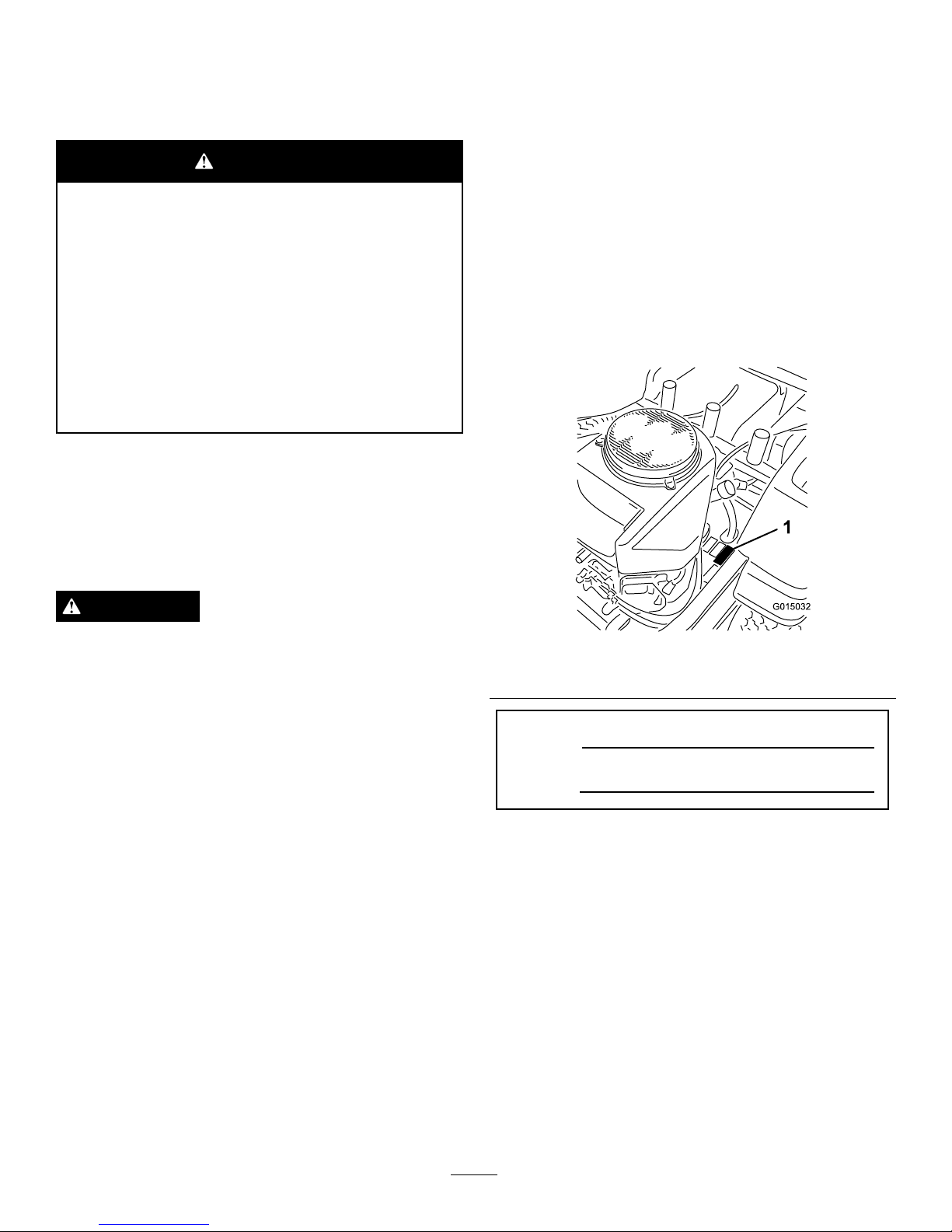
SlopeIndicator
G011841
Figure3
Thispagemaybecopiedforpersonaluse.
1.Themaximumslopeyoucansafelyoperatethemachineonis15degrees.Usetheslopecharttodeterminethedegreeofslope
ofhillsbeforeoperating.Donotoperatethismachineonaslopegreaterthan15degrees.Foldalongtheappropriateline
tomatchtherecommendedslope.
2.Alignthisedgewithaverticalsurface,atree,building,fencepole,etc.
3.Exampleofhowtocompareslopewithfoldededge.
7
Page 8
SafetyandInstructionalDecals
Safetydecalsandinstructionsareeasilyvisibletotheoperatorandarelocatednearanyareaofpotential
danger.Replaceanydecalthatisdamagedorlost.
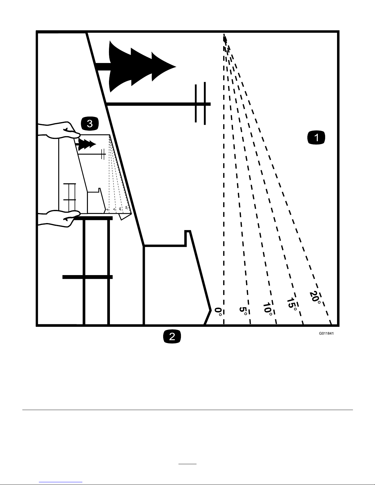
99-8936
1.Machinespeed4.Neutral
2.Fast5.Reverse
3.Slow
109-7076
Manufacturer'sMark
1.Indicatesthebladeisidentiedasapartfromtheoriginal
machinemanufacturer.
114-1606
1.Entanglementhazard,belt—keepallguardsinplace.
115-9625
1.Parking
brake—disengaged
2.Parkingbrake—engaged
115-9632
1.Powertake-off(PTO),
Bladecontrolswitchon
somemodels
5.Fast
2.Bladecontrolswitch—On6.Continuousvariable
setting
3.Bladecontrolswitch—Off7.Slow
4.Choke
8
Page 9
BatterySymbols
Someorallofthesesymbolsareonyourbattery
1.Explosionhazard
6.Keepbystandersasafe
distancefromthebattery.
2.Nore,opename,or
smoking.
7.Weareyeprotection;
explosivegasescan
causeblindnessandother
injuries
3.Causticliquid/chemical
burnhazard
8.Batteryacidcancause
blindnessorsevereburns.
4.Weareyeprotection9.Flusheyesimmediately
withwaterandgetmedical
helpfast.
5.ReadtheOperator's
Manual.
10.Containslead;donot
discard.
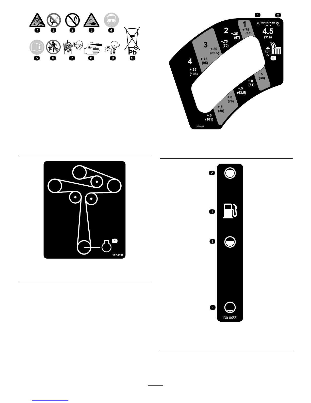
117-1194
1.Engine
130-0654
1.Transport—lock
3.Height-of-cut
2.Transport—unlock
130-0655
1.Fueltank
3.Half
2.Full4.Empty
9
Page 10
130-0731
1.Warning—thrownobject
hazard;keepthedeector
shieldinplace.
2.Cuttinghazardofhandor
foot,mowerblade—keep
awayfrommovingparts.
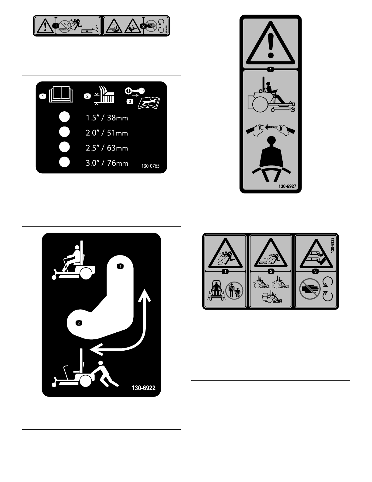
130-0765
1.ReadtheOperator's
Manual.
3.Removethekeyfrom
theignitionandreadthe
Operator'sManualbefore
permorningmaintenance.
2.Height-of-cutselection
130-6922
1.Bypassleverpositionfor
operatingthemachine.
2.Bypassleverpositionfor
pushingthemachine.
130-6927
1.Warning—alwaysusetheROPSandweartheseatbelt
whenseatedintheoperator'sposition.
130-6928
1.Thrownobject
hazard—keepbystanders
awayfromthemachine.
3.Cutting/dismembermentof
handorfoot—stayaway
frommovingparts.
2.Thrownobjecthazard,
mower—donotoperate
thewithoutdeector,
dischargecover,orgrass
collectionsysteminplace.
10
Page 11
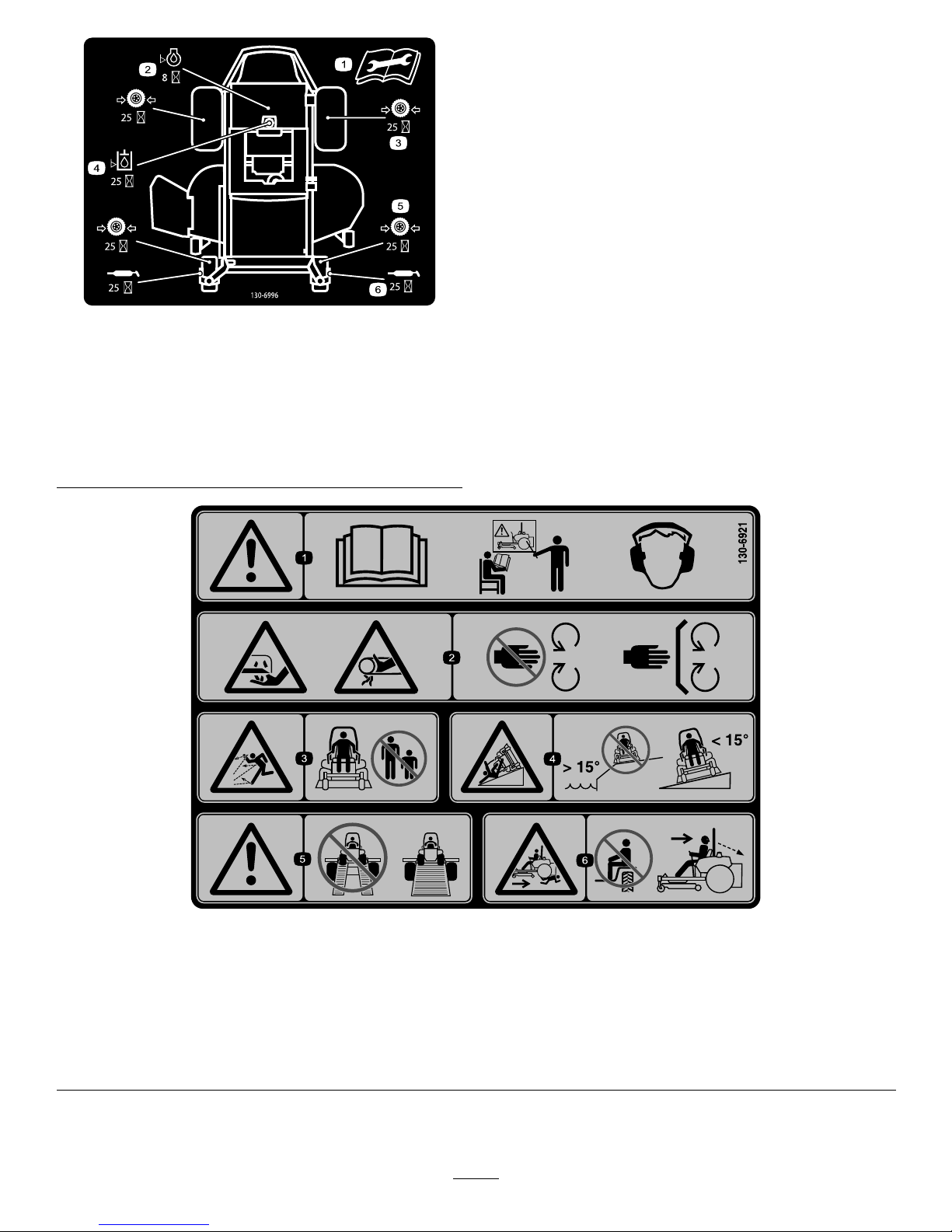
130-6996
1.ReadtheOperator's
Manualforinformationon
maintenance.
4.Checkthehydraulicoil
every25hours
2.Checktheengineoilevery
8hours
5.Checkthecasterwheel
tirepressureevery25
hours
3.Checkthedrivewheeltire
pressureevery25hours
6.Lubricatethecasterwheel
every25hours
130-6921
1.Warning—readtheOperator'sManual;
donotoperatethemachineunlessyou
aretrained;wearhearingprotection.
3.Thrownobjecthazard—keep
bystandersawayfromthemachine.
5.Warning—donotusesplitramps,use
afullrampwhentransportingmachine.
2.Cutting/dismembermenthazard,
mowerblade;entanglementhazard,
belt—stayawayfrommoving
parts,keepallguardsandshieldsin
place.
4.Tippinghazard—donotoperateon
slopesgreaterthan15degreesnear
water;driveacrossslopesgreaterthan
15degrees.
6.Crushing/dismembermenthazardof
bystanders,reversing—donotcarry
passengers,lookbehindanddown
whenreversing.
11
Page 12
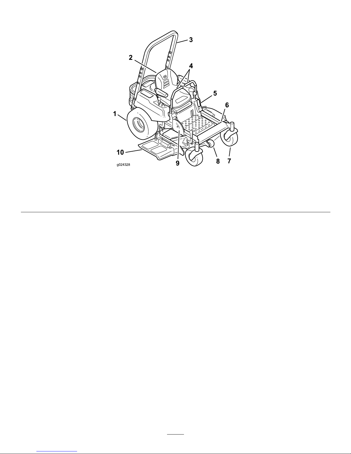
ProductOverview
g024328
2
5
6
8
9
10
3
4
7
1
Figure4
1.Drivewheel4.Motioncontrollevers7.Frontcasterwheel
10.Deector
2.Operatorseat
5.Parkingbrake8.Anti-scalproller
3.Rolloverprotectionsystem
(ROPS)
6.Footrest
9.Footpedaldeckliftand
height-of-cut
12
Page 13
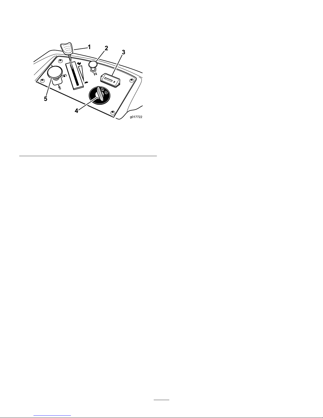
Controls
Becomefamiliarwithallthecontrolsbeforeyoustartthe
engineandoperatethemachine(Figure5).
g017722
1
2
3
4
5
Figure5
1.Throttlecontrol4.Ignitionswitch
2.Choke5.Bladecontrolswitch(PTO)
3.Hourmeter
IgnitionSwitch
Theignitionswitchhasthreepositions:Start,RunandOff.
ThekeywillturntoStartandmovebacktoRunuponrelease.
TurningthekeytotheOffpositionwillstoptheengine;
however,alwaysremovethekeywhenleavingthemachineto
preventtheenginefromaccidentallystarting(Figure5).
ThrottleControl
ThethrottlecontrolisvariablebetweenFastandSlow.
Movingthrottleleverforwardwillincreaseenginespeedand
movingthrottlelevertotherearwilldecreaseenginespeed.
Movingthethrottleforwardintothedetentisfullthrottle
(Figure5).
Choke
Usethechoketostartacoldengine.Pullthechokeknobup
toengageit.Pushdownonthechokeknobtodisengageit.
BladeControlSwitch(PowerTake-Off)
Thebladecontrolswitch,representedbyapowertake-off
(PTO)symbol,engagesanddisengagespowertothemower
blades(
Figure5).
HourMeter
Thehourmeterrecordsthenumberofhoursthebladeshave
operated.Itoperateswhenthebladecontrolswitch(PTO)is
engaged.Usethesetimesforschedulingregularmaintenance
(Figure5).
FuelGauge
Thefuelwindowlocatedbelowtheoperatorpositioncanbe
usedtoverifythelevelofgasolineinthetank(Figure7).
MotionControlLevers
Themotioncontrolleversarespeedsensitivecontrolsof
independentwheelmotors.Movingaleverforwardor
backwardturnsthewheelonthesamesideforwardorin
reverse;wheelspeedisproportionaltotheamountthelever
ismoved.Movethecontrolleversoutwardfromthecenter
totheneutrallockpositionandexitthemachine(Figure4).
Alwayspositionthemotioncontrolleversintotheneutrallock
positionwhenyoustopthemachineorleaveitunattended.
ParkingBrakeLever
Theparkingbrakeleverislocatedonleftsideoftheconsole
(Figure4).Thebrakeleverengagesaparkingbrakeonthe
drivewheels.Pulltheleverupandrearwardtoengagethe
brake.Pushtheleverforwardanddowntodisengagethe
brake.
FootPedalDeckLiftSystem
Thefootpedaldeckliftsystemallowstheoperatortolower
andraisethedeckfromtheseatedposition.Theoperatorcan
usethefootpedaltoliftthedeckbrieytoavoidobstacles
orlockthedeckinthehighestheight-of-cutortransport
position(
Figure4).
Height-of-CutLever
Theheight-of-cutleverworkswiththefootpedaltolockthe
deckinaspeciccuttingheight.Onlyadjusttheheightofcut
whilemachineisnotmoving(Figure4).
Attachments/Accessories
AselectionofToroapprovedattachmentsandaccessoriesis
availableforusewiththemachinetoenhanceandexpand
itscapabilities.ContactyourAuthorizedServiceDealeror
Distributororgotowww .Toro.comforalistofallapproved
attachmentsandaccessories.
13
Page 14
Operation
Note:Determinetheleftandrightsidesofthemachine
fromthenormaloperatingposition.
ThinkSafetyFirst
Pleasecarefullyreadallofthesafetyinstructionsanddecals
inthesafetysection.Knowingthisinformationcouldhelp
you,yourfamily ,pets,orbystandersavoidinjury.
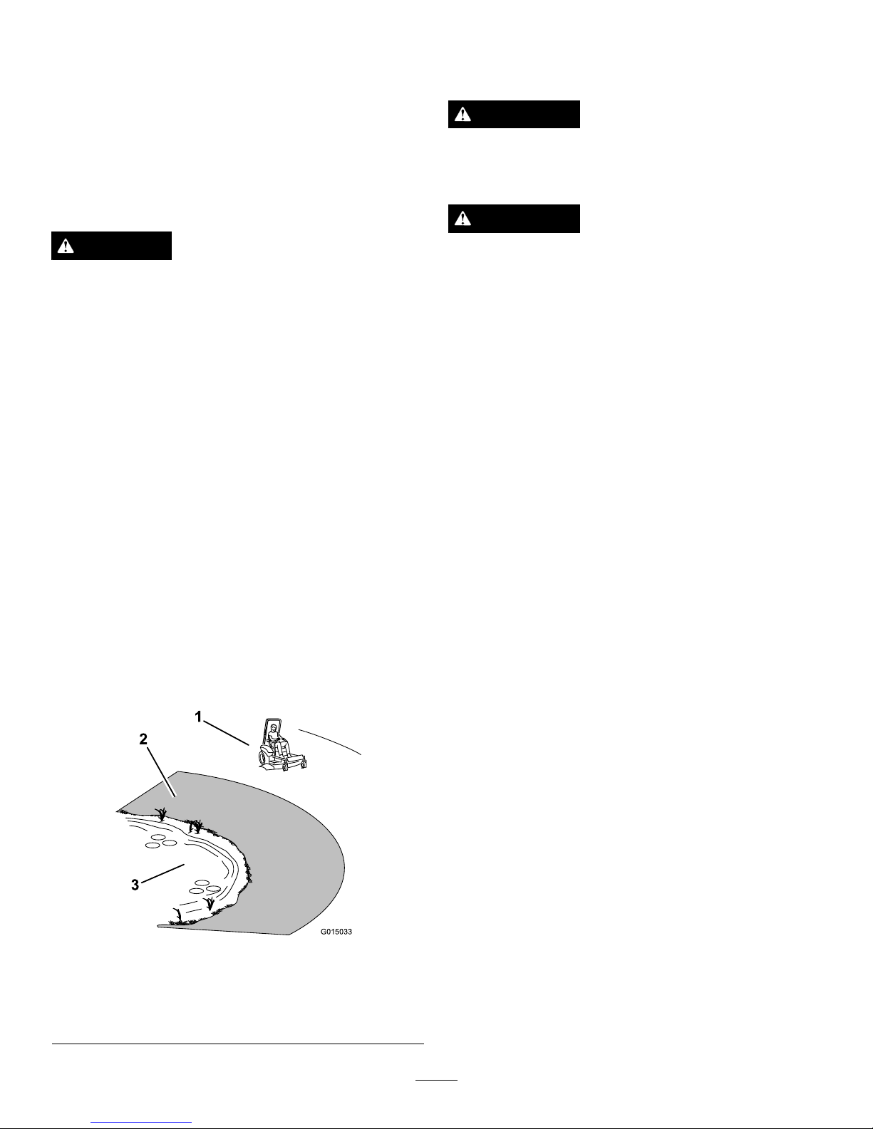
DANGER
Mowingonwetgrassorsteepslopescancause
slidingandlossofcontrol.
Wheelsdroppingoveredgescancauserollovers,
whichmayresultinseriousinjury,deathor
drowning.
Alossoftractionisalossofsteeringcontrol.
Toavoidlossofcontrolandpossibilityofrollover:
•Donotmowneardrop-offsornearwater.
•Donotmowslopesgreaterthan15degrees.
•Reducespeedanduseextremecautionon
slopes.
•Whenmowingslopes,graduallyworkfrom
lowertohigherareasontheincline.
•Avoidsuddenturnsorrapidspeedchanges.
•Turnup,intoaninclinewhenchanging
directionsonslopes.Turningdowntheslope
reducestraction.
•Attachmentschangethehandlingcharacteristics
ofthemachine.Useextracautionwhenusing
attachmentswiththemachine.
G015033
1
2
3
Figure6
1.SafeZone-usethemachinehere
2.Usewalkbehindmowerand/orhandtrimmerneardrop-offs
andwater .
3.Water
UsingtheRolloverProtection
System(ROPS)
WARNING
Toavoidinjuryordeathfromrollover:keeptheroll
barinstalledandusetheseatbelt.
WARNING
Thereisnorolloverprotectionwhentherollbaris
removed.
•Driveslowlyandcarefully.
•Checkcarefullyforoverheadclearances(i.e.
branches,doorways,electricalwires)before
drivingunderanyobjectsanddonotcontact
them.
14
Page 15

AddingFuel
•Forbestresults,useonlyclean,fresh(lessthan30days
old),unleadedgasolinewithanoctaneratingof87or
higher((R+M)/2ratingmethod).
•Ethanol:Gasolinewithupto10%ethanol(gasohol)
or15%MTBE(methyltertiarybutylether)byvolume
isacceptable.EthanolandMTBEarenotthesame.
Gasolinewith15%ethanol(E15)byvolumeisnot
approvedforuse.Neverusegasolinethatcontains
morethan10%ethanolbyvolume,suchasE15
(contains15%ethanol),E20(contains20%ethanol),or
E85(containsupto85%ethanol).Usingunapproved
gasolinemaycauseperformanceproblemsand/orengine
damagewhichmaynotbecoveredunderwarranty.
•Donotusegasolinecontainingmethanol.
•Donotstorefueleitherinthefueltankorfuelcontainers
overthewinterunlessafuelstabilizerisused.
•Donotaddoiltogasoline.
DANGER
Incertainconditions,gasolineisextremely
ammableandhighlyexplosive.Areorexplosion
fromgasolinecanburnyouandothersandcan
damageproperty.
•Fillthefueltankoutdoors,inanopenarea,
whentheengineiscold.Wipeupanygasoline
thatspills.
•Neverllthefueltankinsideanenclosedtrailer.
•Donotllthefueltankcompletelyfull.Add
gasolinetothefueltankuntilthelevelis6to13
mm(1/4to1/2inch)belowthebottomofthe
llerneck.Thisemptyspaceinthetankallows
gasolinetoexpand.
•Neversmokewhenhandlinggasoline,andstay
awayfromanopenameorwheregasoline
fumesmaybeignitedbyaspark.
•Storegasolineinanapprovedcontainerand
keepitoutofthereachofchildren.Neverbuy
morethana30-daysupplyofgasoline.
•Donotoperatewithoutentireexhaustsystemin
placeandinproperworkingcondition.
DANGER
Incertainconditionsduringfueling,static
electricitycanbereleasedcausingasparkwhich
canignitethegasolinevapors.Areorexplosion
fromgasolinecanburnyouandothersandcan
damageproperty.
•Alwaysplacegasolinecontainersontheground
awayfromyourvehiclebeforelling.
•Donotllgasolinecontainersinsideavehicleor
onatruckortrailerbedbecauseinteriorcarpets
orplastictruckbedlinersmayinsulatethe
containerandslowthelossofanystaticcharge.
•Whenpractical,removegas-poweredequipment
fromthetruckortrailerandrefueltheequipment
withitswheelsontheground.
•Ifthisisnotpossible,thenrefuelsuch
equipmentonatruckortrailerfromaportable
container,ratherthanfromagasolinedispenser
nozzle.
•Ifagasolinedispensernozzlemustbeused,
keepthenozzleincontactwiththerimofthe
fueltankorcontaineropeningatalltimesuntil
fuelingiscomplete.
WARNING
Gasolineisharmfulorfatalifswallowed.Long-term
exposuretovaporscancauseseriousinjuryand
illness.
•Avoidprolongedbreathingofvapors.
•Keepfaceawayfromnozzleandgastankor
conditioneropening.
•Keepgasawayfromeyesandskin.
UsingStabilizer/Conditioner
Useafuelstabilizer/conditionerinthemachinetoprovide
thefollowingbenets:
•Fuelstabilizer/conditionerkeepsgasolinefreshduring
storageof90daysorless.Whenstoringthemachinefor
longerperiods,drainthefuelsystem.
•Itcleanstheenginewhileitruns
•Iteliminatesgum-likevarnishbuildupinthefuelsystem,
whichcauseshardstarting
Important:Donotusefueladditivescontaining
methanolorethanol.
Addthecorrectamountofgasstabilizer/conditionertothe
gas.
Note:Afuelstabilizer/conditionerismosteffectivewhen
mixedwithfreshgasoline.Tominimizethechanceofvarnish
depositsinthefuelsystem,usefuelstabilizeratalltimes.
15
Page 16
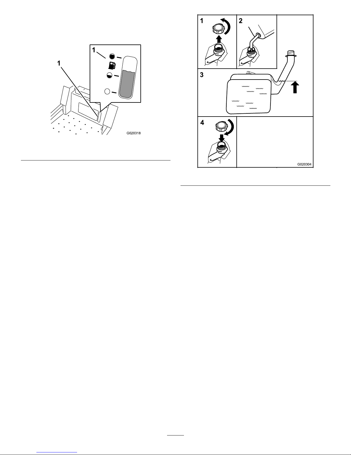
FuelGauge
Usethefuelwindowbelowtheoperatortoverifythelevelof
gasolinebeforellingthetank(Figure7).
G020318
1
1
Figure7
1.Fuelgaugewindow
FillingtheFuelTank
Makesuretheengineisshutoffandthemotioncontrolsare
intheparkposition.
Important:Donotoverllfueltank.Fillthefueltank
tothebottomofthellerneck.Theemptyspaceinthe
tankallowsthefueltoexpand.Overllingmayresultin
fuelleakageordamagetotheengineoremissionsystem.
1.Cleanaroundthefueltankcapandremovethecap.
Note:Youcanusethefuelwindowbelowthe
operatingpositionverifythepresenceofgasoline
beforellingthetank(Figure7).
2.Slowlyaddregular,unleadedgasolineuntilthefuel
reachesthebaseofthellerneckFigure8.
G020304
1
2
3
4
Figure8
3.Installthefueltankcapsecurelyandtightenuntilit
“clicks.”Wipeupanygasolinethatmayhavespilled.
CheckingtheEngineOilLevel
Beforeyoustarttheengineandusethemachine,checktheoil
levelintheenginecrankcase;refertoCheckingtheEngine
OilLevel(page29).
16
Page 17

OperatingtheParkingBrake
Alwayssettheparkingbrakewhenyoustopthemachineor
leaveitunattended.
SettingtheParkingBrake
1
2
G020305
Figure9
ReleasingtheParkingBrake
1
2
G020306
Figure10
OperatingtheThrottle
ThethrottlecontrolcanbemovedbetweenFastandSlow
positions(Figure11).
Alwaysusethefastpositionwhenturningonthemowerdeck
withthebladecontrolswitch(PTO).
G008946
Figure11
OperatingtheChoke
Usethechoketostartacoldengineasfollows:
1.Pulluponthechokeknobtoengagethechokebefore
usingtheignitionswitch(Figure12).
2.Pushdownonthechoketodisengagethechokeafter
theenginehasstarted(Figure12).
G008959
1
2
Figure12
1.On2.Off
OperatingtheIgnitionSwitch
1.TurntheignitionkeytotheStartposition(Figure13).
Whentheenginesstarts,releasethekey .
Important:Donotengagestarterformorethan5
secondsatatime.Iftheenginefailstostartallow
a15secondcool-downperiodbetweenattempts.
Failuretofollowtheseinstructionscanburnout
thestartermotor.
Note:Additionalstartingcyclesmayberequired
whenstartingtheengineforthersttimeafterthefuel
systemhasbeenwithoutfuelcompletely.
START
RUN
STOP
G008947
Figure13
2.Tostoptheengine,turntheignitionkeytothestop
position.
17
Page 18

StartingandStoppingthe
Engine
StartingtheEngine
1.Sitdownontheseat(Figure14).
2.Movethemotioncontrolsoutwardtotheneutrallock
position(Figure14).
3.Settheparkingbrake(Figure10);refertoSettingthe
ParkingBrake.
4.Movethebladecontrolswitch(PTO)totheOff
position(
Figure14).
5.PullupontheChokecontrolbeforestartingacold
engine.
Note:Awarmorhotenginemaynotrequirechoking.
6.Movethethrottlehalfwaybetweenthefastandslow
positions(Figure14).
g017965
2
3
4
5
1
6
Figure14
7.TurntheignitionkeytotheStartposition(Figure13).
Whentheenginesstarts,releasethekey .
Important:Donotengagestarterformorethan5
secondsatatime.Iftheenginefailstostartallow
a15secondcool-downperiodbetweenattempts.
Failuretofollowtheseinstructionscanburnout
thestartermotor.
8.Aftertheenginestarts,pushdownontheChoke
control.Iftheenginestallsorhesitates,pullupon
theChokecontrolandlettheenginerunforafew
seconds.ThenpushdowntheChokecontrol.Repeat
asrequired.
Note:Ifthefuelsystemwasdepletedoffuel—add
fueltothemachineanduseadditionalstartingcycles
whenstartingtheengine.
StoppingtheEngine
CAUTION
Injurycanoccurifchildrenorbystandersmove
orattempttooperatethemachinewhileitis
unattended.
Alwaysremovetheignitionkeyandsettheparking
brakewhenleavingthemachineunattended,even
ifjustforafewminutes.
S
T
A
R
T
R
U
N
S
T
O
P
2
3
4
5
1
00:60 Sec
g017981
Figure15
OperatingtheMowerBlade
ControlSwitch(PTO)
Thebladecontrolswitch(PTO)startsandstopsthemower
bladesandanypoweredattachments.
18
Page 19

EngagingtheBladeControlSwitch
(PTO)
Toengagethemowerbladesperformthefollowing:
1.SetthethrottletothepositionatFastposition;referto
OperatingtheThrottle(page17).
2.Pullupontheblade-control(PTO)switch.
Note:Engagingthebladecontrolswitch(PTO)withthe
throttlepositionathalforlesswillcauseexcessivewearto
thedrivebelts.
G008945
Figure16
DisengagingtheBladeControlSwitch
(PTO)
Todisengagethemowerblades,pushdownonthe
blade-control(PTO)switch.
G009174
Figure17
TheSafetyInterlockSystem
WARNING
Ifsafetyinterlockswitchesaredisconnectedor
damagedthemachinecouldoperateunexpectedly
causingpersonalinjury.
•Donottamperwiththeinterlockswitches.
•Checktheoperationoftheinterlockswitches
dailyandreplaceanydamagedswitchesbefore
operatingthemachine.
UnderstandingtheSafetyInterlock
System
Thesafetyinterlocksystemisdesignedtopreventtheengine
fromstartingunless:
•Theparkingbrakeisengaged.
•Thebladesaredisengaged.
•Themotioncontrolleversareintheneutrallockposition.
Thesafetyinterlocksystemalsoisdesignedtostoptheengine
whenthecontrolleversareoutoftheneutrallockposition
withtheparkingbrakeonorifyourisefromtheseatwhen
thebladesareengaged.
TestingtheSafetyInterlockSystem
Testthesafetyinterlocksystembeforeyouusethemachine
eachtime.Ifthesafetysystemdoesnotoperateasdescribed
below,haveanAuthorizedServiceDealerrepairthesafety
systemimmediately.
1.Whilesittingontheseat,engagetheparkingbrakeand
movethebladecontrolswitchtoOn.Trystartingthe
engine;theengineshouldnotcrank.
2.Whilesittingontheseat,engagetheparkingbrakeand
movethebladecontrolswitchtoOff.Moveeither
motioncontrollever(forwardorreverse).Trystarting
theengine;theengineshouldnotcrank.Repeatwith
theothermotioncontrollever.
3.Whilesittingontheseat,engagetheparkingbrake,
movethebladecontrolswitchtoOff,andlockthe
motioncontrolleversinneutral.Starttheengine.
Whiletheengineisrunning,releasetheparkingbrake,
engagethebladecontrolswitch,andriseslightlyfrom
theseat;theengineshouldstop.
4.Whilesittingontheseat,engagetheparkingbrake,
movethebladecontrolswitchtoOff,andlockthe
motioncontrolleversinneutral.Starttheengine.
Whiletheengineisrunning,centerthemotion
controls;theengineshouldstop.
19
Page 20

DrivingForwardorBackward
Thethrottlecontrolregulatestheenginespeedasmeasured
inrpm(revolutionsperminute).Placethethrottlecontrolin
thefastpositionforbestperformance.Alwaysoperateinthe
fullthrottlepositionwhenmowing.
CAUTION
Machinecanspinveryrapidly.Operatormaylose
controlofmachineandcausepersonalinjuryor
damagetomachine.
•Usecautionwhenmakingturns.
•Slowthemachinedownbeforemakingsharp
turns.
UsingtheMotionControlLevers
Figure18
1.Motioncontrol
lever-neutrallockposition
4.Backward
2.Center,unlockedposition5.Frontofmachine
3.Forward
DrivingForward
Note:Theenginewillkillifthetractioncontrolleversare
movedwiththeparkingbrakeengaged.
1.Releasetheparkingbrake;refertoReleasingthe
ParkingBrake(page17).
2.Movetheleverstothecenter,unlockedposition.
3.Togoforward,slowlypushthemotioncontrollevers
forward(
Figure19).
G008952
Figure19
DrivingBackward
1.Movetheleverstothecenter,unlockedposition.
2.Togobackward,slowlypullthemotioncontrollevers
rearward(Figure20).
G008953
Figure20
20
Page 21

StoppingtheMachine
Tostopthemachine,movethetractioncontrolleversto
neutralandmovetolockedposition,disengagetheblade
controlswitch(PTO),andturntheignitionkeytooff.
Settheparkingbrakewhenyouleavethemachine;referto
SettingtheParkingBrake(page17).Remembertoremove
thekeyfromtheignitionswitch.
CAUTION
Childrenorbystandersmaybeinjuredifthey
moveorattempttooperatethemachinewhileitis
unattended.
Alwaysremovetheignitionkeyandsettheparking
brakewhenleavingthemachineunattended,even
ifjustforafewminutes.
AdjustingtheHeight-of-Cut
Themachineisequippedwithafootpedaldeckliftsystem.
Theoperatorcanusethefootpedaltoliftthedeckbrieyto
avoidobstaclesorlockthedeckinthehighestheight-of-cut
ortransportposition.Theoperatorcanusetheheightof
cutleverwiththefootpedaltolockthedeckinaspecic
cuttingheight.
UsingtheFootPedalDeckLiftSystem
•Pressthepedaldowntoraisethedeck;continuetopress
thepedaluntilthedeckislockedinthetransportposition
(Figure21).
•Pushonthedeckliftpedalwithyourfootandpullthe
transportlockhandlerearwardtodisengagethetransport
lock(Figure21).
g024409
Figure21
TransportLockPosition
AdjustingtheHeight-of-Cut
Theheight-of-cutcanbeadjustedfrom38to114mm(1-1/2
to4-1/2inch)in6mm(1/4inch)incrementsbyrelocating
theheight-of-cutpinintodifferentholelocations.
1.Pushonthedeckliftpedalwithyourfootandraisethe
mowerdecktothetransportlockposition(alsothe
114mm(4-1/2inch)cuttingheightposition)(Figure
22).
2.Toadjust,removethepinfromtheheight-of-cut
bracket(
Figure22).
3.Selectaholeintheheight-of-cutsystemcorresponding
totheheight-of-cutdesiredandinsertthepin(Figure
22).
21
Page 22

4.Pushonthedeckliftpedalwithyourfootandpull
thehandlerearwardtodisengagethetransportlock
(Figure21).
5.Lowerthedeckslowlyuntilthelevermakescontact
withthepin.
g024410
1
2
3
4
Figure22
1.Deckliftpedal3.Height-of-cutpositions
2.Handle4.Pin
AdjustingtheAnti-Scalp
Rollers
Wheneveryouchangetheheight-of-cut,itisrecommended
toadjusttheheightoftheanti-scalprollers.
1.Disengagethebladecontrolswitch(PTO),movethe
motioncontrolleverstotheneutrallockpositionand
settheparkingbrake.
2.Stoptheengine,removethekey,andwaitforallmoving
partstostopbeforeleavingtheoperatingposition.
3.Removetheangenut,anti-scalprollerandboltfrom
thebracket(
Figure23).
Note:Keeptheboltandanti-scalprollertogether
whenremoving.
g024312
1
2 3 4
5
Figure23
1.FlangeNut4.Bushing
2.Spacer
5.Bolt
3.Anti-scalproller
4.Aligntheboltandanti-scalprollerintheholeofthe
bracketthatmatchedtheclosestheightofcutposition
(Figure23).
5.Inserttheboltintothebracketholeandsecurethebolt
andanti-scalprollerwiththeangenut(Figure23).
22
Page 23

PositioningtheSeat
Theseatcanmoveforwardandbackward.Positiontheseat
whereyouhavethebestcontrolofthemachineandaremost
comfortable.
Whilesittingintheoperator'sposition,raisetheseat
adjustmentleverslightlyandmovetheseatforwardor
backwardtothedesiredposition(Figure24).
G010232
1
Figure24
1.Adjustmentlever
AdjustingtheMotionControl
Levers
AdjustingtheHeight
Themotioncontrolleverscanbeadjustedhigherorlowerfor
maximumoperatorcomfort.
1.Removethe2boltsand2washersholdingthecontrol
levertothecontrolarmshaft(Figure25).
2.Movethecontrollevertothenextsetofholes.Secure
theleverwiththe2boltsand2washers(Figure25).
4
1
2
G014970
3
Figure25
1.Controlarmshaft
4.Washer
2.Controllever
5.Bolt
3.Slotted,upperhole
3.Repeattheadjustmentfortheoppositecontrollever.
AdjustingtheTilt
Themotioncontrolleverscanbetiltedforwardorbackward
formaximumoperatorcomfort.
1.Loosentheupperboltholdingthecontrollevertothe
controlarmshaft.
2.Loosenthelowerboltjustenoughtoallowthecontrol
levertopivotforwardorbackward.
3.Alignthecontrolleverstothenewposition.
4.Tightenbothboltstosecurethecontrolleverposition.
5.Repeatsteps1,2,3and4toadjustmentfortheother
controllever.
23
Page 24

PushingtheMachinebyHand
Important:T owingthemachinewilldamagethe
drivetrainofthemachine.
Alwayspushthemachinebyhand.
ToPushtheMachine
1.Parkthemachineonalevelsurfaceanddisengagethe
bladecontrolswitch.
2.Engagetheparkingbrake
3.Movethemotioncontrolleversoutwardtoneutrallock
position,stoptheengine,removethekey ,andwaitfor
allmovingpartstostopbeforeleavingtheoperating
position.
4.Locatethebypassleversattherearofthemachine,on
theleftandrightsideoftheframe.
5.Movethebypassleversrearwardandthendownto
locktheminplaceasshownin
Figure26todisengage
thewheelmotors.
Note:Ensurethattheleftandrightbypassleversare
rearwardandlockedbeforemovingthemachine.
6.Disengagetheparkingbrake
Themachineisnowabletobepushedbyhand.
1 2
3 4
G024554
Figure26
ToOperatetheMachine
Movethebypasstothepositionforoperatingthemachine
(
Figure26)toengagethewheelmotors.
UsingtheSideDischarge
Themowerhasahingedgrassdeectorthatdisperses
clippingstothesideanddowntowardtheturf.
DANGER
Withoutagrassdeector,dischargecover,or
completegrasscatcherassemblymountedin
place,youandothersareexposedtobladecontact
andthrowndebris.Contactwithrotatingmower
blade(s)andthrowndebriswillcauseinjuryor
death.
•Neverremovethegrassdeectorfromthemower
becausethegrassdeectorroutesmaterialdown
towardtheturf.Ifthegrassdeectorisever
damaged,replaceitimmediately .
•Neverputyourhandsorfeetunderthemower.
•Nevertrytoclearthedischargeareaormower
bladesunlessyoumovethebladecontrolswitch
(PTO)totheoffposition,rotatetheignitionkey
tooffandremovethekey .
•Makesurethegrassdeectorisinthedown
position.
24
Page 25

OperatingTips
FastThrottleSetting
Forbestmowingandmaximumaircirculation,operate
theengineatthefastthrottleposition.Airisrequiredto
thoroughlycutgrassclippings,sodonotsettheheight-of-cut
solowastototallysurroundthemowerbyuncutgrass.
Alwaystrytohaveonesideofthemowerfreefromuncut
grass,whichallowsairtobedrawnintothemower.
CuttingaLawnfortheFirstTime
Cutgrassslightlylongerthannormaltoensurethecutting
heightofthemowerdoesnotscalpanyunevenground.
However,thecuttingheightusedinthepastisgenerallythe
bestonetouse.Whencuttinggrasslongerthansixinchestall,
youmaywanttocutthelawntwicetoensureanacceptable
qualityofcut.
Cut1/3oftheGrassBlade
Itisbesttocutonlyabout1/3ofthegrassblade.Cutting
morethanthatisnotrecommendedunlessgrassissparse,or
itislatefallwhengrassgrowsmoreslowly.
MowingDirection
Alternatemowingdirectiontokeepthegrassstanding
straight.Thisalsohelpsdisperseclippingswhichenhances
decompositionandfertilization.
MowatCorrectIntervals
Normally,moweveryfourdays.Butremember,grassgrows
atdifferentratesatdifferenttimes.Sotomaintainthesame
cuttingheight,whichisagoodpractice,mowmoreoftenin
earlyspring.Asthegrassgrowthrateslowsinmidsummer,
mowlessfrequently.Ifyoucannotmowforanextended
period,rstmowatahighcuttingheight;thenmowagain
twodayslateratalowerheightsetting.
CuttingSpeed
Toimprovecutquality,useaslowergroundspeedincertain
conditions.
AvoidCuttingTooLow
Ifthecuttingwidthofthemoweriswiderthanthemower
youpreviouslyused,raisethecuttingheighttoensurethat
uneventurfisnotcuttooshort.
LongGrass
Ifthegrassiseverallowedtogrowslightlylongerthan
normal,orifitcontainsahighdegreeofmoisture,raisethe
cuttingheighthigherthanusualandcutthegrassatthis
setting.Thencutthegrassagainusingthelower,normal
setting.
WhenStopping
Ifthemachine'sforwardmotionmustbestoppedwhile
mowing,aclumpofgrassclippingsmaydropontoyourlawn.
Toavoidthis,moveontoapreviouslycutareawiththeblades
engaged.
KeeptheUndersideoftheMowerClean
Cleanclippingsanddirtfromtheundersideofthemower
aftereachuse.Ifgrassanddirtbuildupinsidethemower,
cuttingqualitywilleventuallybecomeunsatisfactory.
BladeMaintenance
Maintainasharpbladethroughoutthecuttingseasonbecause
asharpbladecutscleanlywithouttearingorshreddingthe
grassblades.Tearingandshreddingturnsgrassbrownat
theedges,whichslowsgrowthandincreasesthechanceof
disease.Checkthecutterbladesdailyforsharpness,andfor
anywearordamage.Filedownanynicksandsharpenthe
bladesasnecessary.Ifabladeisdamagedorworn,replaceit
immediatelywithagenuineT ororeplacementblade.
25
Page 26

Maintenance
RecommendedMaintenanceSchedule(s)
MaintenanceService
Interval
MaintenanceProcedure
Aftertherst8hours
•Changetheengineoil.
Aftertherst50hours
•Changethehydraulicsystemlterandoil.
Beforeeachuseordaily
•Checkthesafetyinterlocksystem.
•Checktheengineoillevel.
•Cleantheairintakescreen.
•Checkthemowerblades.
•Inspectthegrassdeectorfordamage
Aftereachuse
•Cleanthemowerhousing.
Every25hours
•Greasealllubricationpoints.
•Checktirepressure.
•Checkthehydraulicoillevelintheexpansiontank.
Every50hours
•Inspectthebeltsforcracksandwear.
Every100hours
•Servicethepaperelement.(moreoftenindusty,dirtyconditions)
•Changetheengineoil.(moreoftenindusty ,dirtyconditions)
•Checkthesparkplug(s).
•Replacethefuellter(moreoftenunderdusty,dirtyconditions).
•Replacetheemissionslter(model74855only).
Every200hours
•Replacethepaperelement.(moreoftenindusty,dirtyconditions)
•Changetheoillter.(moreoftenindusty,dirtyconditions)
Every400hours
•Changethehydraulicsystemlterandoil.
Monthly
•Checkthebatterycharge.
Yearlyorbeforestorage
•Paintchippedsurfaces.
•Checkallmaintenanceprocedureslistedabovebeforestorage.
Important:Refertoyourengineoperator'smanualforadditionalmaintenanceprocedures.
CAUTION
Ifyouleavethekeyintheignitionswitch,someonecouldaccidentlystarttheengineandseriouslyinjure
youorotherbystanders.
Removethekeyfromtheignitionanddisconnectthewirefromthesparkplugbeforeyoudoany
maintenance.Setthewireasidesothatitdoesnotaccidentallycontactthesparkplug.
26
Page 27

Figure27
Locatedontheseatpanunderside
1.ReadtheOperator'sManualforinformationonmaintenance.4.Checkthehydraulicoilevery25hours
2.Checktheengineoilevery8hours5.Checkthecasterwheeltirepressureevery25hours
3.Checkthedrivewheeltirepressureevery25hours
6.Lubricatethecasterwheelevery25hours
Premaintenance
Procedures
RaisingtheSeat
Makesurethemotioncontrolleversarelockedintheneutral
lockposition.Lifttheseatforward.
Thefollowingcomponentscanbeaccessedbyraisingtheseat:
•Servicedecal
•Fuses
•Batteryandcables
Lubrication
GreasingtheBearings
ServiceInterval:Every25hours—Greasealllubrication
points.
GreaseType:No.2GeneralPurposeLithiumBaseGrease
1.Parkthemachineonalevelsurfaceanddisengagethe
bladecontrolswitch.
2.Movethemotioncontrolleversoutwardtotheneutral
lockposition,stoptheengine,removethekey ,and
waitforallmovingpartstostopbeforeleavingthe
operatingposition.
3.Cleanthegreasettingswitharag(
Figure27and
Figure28).Makesuretoscrapeanypaintoffofthe
frontofthetting(s).
27
Page 28

G009949
1
Figure28
1.Frontcastertire
4.Connectagreaseguntoeachtting(Figure28and
Figure27).Pumpgreaseintothettingsuntilgrease
beginstooozeoutofthebearings.
5.Wipeupanyexcessgrease.
EngineMaintenance
WARNING
Contactwithhotsurfacesmaycausepersonal
injury.
Keephands,feet,face,clothingandotherbody
partsawaythemuferandotherhotsurfaces.
ServicingtheAirCleaner
Note:Servicetheaircleanermorefrequently(everyfew
hours)ifoperatingconditionsareextremelydustyorsandy.
RemovingtheElement
1.Parkthemachineonalevelsurfaceanddisengagethe
bladecontrol(PTO).
2.Movethemotioncontrolleverstothebrakeposition,
stoptheengine,removethekey,andwaitforallmoving
partstostopbeforeleavingtheoperatingposition.
3.Cleanaroundtheaircleanercovertopreventdirtfrom
gettingintotheengineandcausingdamage.
4.Liftthecoverandremovethehoseclampsecuringthe
aircleanerassemblytotheengine(
Figure29).
5.Loosenthehoseclampandremovethepaperelement
(Figure29).
G015155
1
2
3
Figure29
1.Cover
3.Hoseclamp
2.Paperelement
28
Page 29

CleaningtheElement
ServiceInterval:Every100hours—Servicethepaper
element.(moreoftenindusty ,dirty
conditions)
Every200hours/Yearly(whichevercomes
rst)—Replacethepaperelement.(moreoftenin
dusty,dirtyconditions)
1.Lightlytaptheelementonaatsurfacetoremovedust
anddirt.
2.Inspecttheelementfortears,anoilylm,anddamage
totheseal.
Important:Nevercleanthepaperelementwith
pressurizedairorliquids,suchassolvent,gas,
orkerosene.Replacethepaperelementifitis
damagedorcannotbecleanedthoroughly.
ServicingtheEngineOil
EngineOilSpecication
OilType:Detergentoil(APIserviceSF,SG,SH,SJ,orSL)
CrankcaseCapacity:1.8liter(61ounce);whenoillteris
removed:2.1liter(70ounce)
Viscosity:Seethetablebelow:
g017470
SAE V iscosity Grades
SAE 40
SAE 30
SAE 10W– 30/ SAE 10W– 40
-20 0 20 32 40 60 80 100
-30 -20 -10 0 10 20 30 40
°F
°C
STARTING TEMPERA TURE RANGE ANTICIPATED BEFORE NEXT OIL CHANGE
SAE 5W– 20
Figure30
Note:Usingmulti-gradeoils(5W-20,10W-30,and10W -40)
willincreaseoilconsumption.Checkoillevelmorefrequently
whenusingthem.
CheckingtheEngineOilLevel
ServiceInterval:Beforeeachuseordaily
Note:Checktheoilwhentheengineiscold.
WARNING
Contactwithhotsurfacesmaycausepersonal
injury.
Keephands,feet,face,clothingandotherbody
partsawaythemuferandotherhotsurfaces.
Important:Donotoverllthecrankcasewithoil
becausedamagetotheenginemayresult.Donotrun
enginewithoilbelowthelowmarkbecausetheengine
maybedamaged.
1.Parkthemachineonalevelsurface,disengagethe
bladecontrolswitch,stoptheengine,engageparking
brake,andremovethekey.
2.Makesuretheengineisstopped,level,andiscoolso
theoilhashadtimetodrainintothesump.
3.Tokeepdirt,grassclippings,etc.,outoftheengine,
cleantheareaaroundtheoilllcap/dipstickbefore
removingit(
Figure31).
1
2
4
5
7
9
10
G0201 15
Figure31
29
Page 30

ChangingtheEngineOil
ServiceInterval:Aftertherst8hours—Changetheengine
oil.
Every100hours—Changetheengineoil.(moreoften
industy ,dirtyconditions)
Note:Disposeoftheusedoilatarecyclingcenter.
1.Parkthemachinesothatthedrainsideisslightly
lowerthantheoppositesidetoassuretheoildrains
completely.
2.DisengagethePTO ,movethemotioncontrolleversto
theneutrallockedpositionandsettheparkingbrake.
3.Stoptheengine,removethekey,andwaitforall
movingpartstostopbeforeleavingtheoperating
position(
Figure32).
1
2
4
6
G0201 16
Figure32
4.Slowlypourapproximately80%ofthespeciedoil
intothellertubeandslowlyaddtheadditionaloilto
bringittotheFullmark(Figure33).
1
2
4
6
G0201 17
Figure33
30
Page 31

ChangingtheEngineOilFilter
ServiceInterval:Every200hours—Changetheoillter.
(moreoftenindusty,dirtyconditions)
Note:Changetheengineoilltermorefrequentlywhen
operatingconditionsareextremelydustyorsandy.
1.Draintheoilfromtheengine;refertoChangingthe
EngineOil(page30).
2.Changetheengineoillter(
Figure34).
1
2
4
6
3/4
G0201 18
Figure34
Note:Ensuretheoilltergaskettouchestheengine
andthenanextra3/4turniscompleted.
3.Fillthecrankcasewiththepropertypeofnewoil;refer
toChangingtheEngineOil(page30).
ServicingtheSparkPlug
ServiceInterval:Every100hours—Checkthesparkplug(s).
Makesuretheairgapbetweenthecenterandsideelectrodes
iscorrectbeforeinstallingthesparkplug.Useaspark-plug
wrenchforremovingandinstallingthesparkplug(s)anda
gappingtool/feelergaugetocheckandadjusttheairgap.
Installanewsparkplug(s)ifnecessary.
Type:NGKBPR4ES(orequivalent)
AirGap:0.76mm(0.030inch)
RemovingtheSparkPlug
1.DisengagethePTO ,movethemotioncontrolleversto
theneutrallockedpositionandsettheparkingbrake.
2.Stoptheengine,removethekey,andwaitforallmoving
partstostopbeforeleavingtheoperatingposition.
1
2
G020130
Figure35
Note:Blowingoutthecavitywithcompressedairis
usuallythemosteffectivemethodforcleaning.The
sparkplugismostaccessiblewhentheblowerhousing
isremovedforcleaning.
CheckingtheSparkPlug
Important:Nevercleanthesparkplug(s).Always
replacethesparkplug(s)whenithasablackcoating,
wornelectrodes,anoilylm,orcracks.
Ifyouseelightbrownorgrayontheinsulator,theengineis
operatingproperly .Ablackcoatingontheinsulatorusually
meanstheaircleanerisdirty.
Setthegapto0.76mm(0.030inch).
1
2
G020131
Figure36
31
Page 32

InstallingtheSparkPlug
Tightenthesparkplug(s)to22N-m(16ft-lb).
1
2
4
16 ft-lb
22 N-m
G020315
Figure37
CleaningtheCoolingSystem
Cleantheairintakescreenfromgrassanddebrisbeforeeach
use.
1.Disengagethebladecontrolswitch,movethecontrol
leverstotheneutrallockedposition,andapplythe
parkingbrake.
2.Stoptheengine,removethekey,andwaitforallmoving
partstostopbeforeleavingtheoperatingposition.
3.Removetheairintakescreen,aircleanercover,and
fanhousing.
4.Cleandebrisandgrassfromtheparts.
5.Installtheairintakescreen,aircleanercover,andfan
housing.
FuelSystem
Maintenance
DANGER
Incertainconditions,gasolineisextremely
ammableandhighlyexplosive.Areorexplosion
fromgasolinecanburnyouandothersandcan
damageproperty.
•Performanyfuelrelatedmaintenancewhenthe
engineiscold.Dothisoutdoorsinanopenarea.
Wipeupanygasolinethatspills.
•Neversmokewhendraininggasoline,andstay
awayfromanopenameorwhereasparkmay
ignitethegasolinefumes.
ReplacingtheFuelFilter
ServiceInterval:Every100hours/Yearly(whichevercomes
rst)(moreoftenunderdusty ,dirty
conditions).
1.Disengagethebladecontrolswitch(PTO),movethe
motioncontrolleverstotheneutrallockposition,and
settheparkingbrake.
2.Stoptheengine,removethekey,andwaitforallmoving
partstostopbeforeleavingtheoperatingposition.
3.Allowthemachinetocooldown.
4.Raisetheseatandlocatethefuelltersasshownin
Figure38.
g017723
1
2
3
4
5
Figure38
1.Fuellinefromtank
4.Fuellinetoengine
2.In-lineFuellter
5.Hoseclamp
3.Flowdirectionarrow
5.Squeezetheendsofthehoseclampstogetherandslide
themawayfromthelter(Figure39).
32
Page 33

G008963
12
3
Figure39
1.Fuellter
3.Fuelline
2.Hoseclamp
6.Removethelterfromthefuellines.
7.Installanewlterwiththeowdirectionarrowcoming
fromthefueltankandpointingtotheengine.Move
thehoseclampsclosetothelter(
Figure38)tosecure
itinplace.
ServicingtheEmissionsFilter
ServiceInterval:Every100hours/Yearly(whichevercomes
rst)
Model74855only
Note:CARBcompliantmodel74845isequippedwitha
maintenancefreeemissionscanisterandhasanemissions
ltertobeserviced.
Thelterislocatedbehindtheoperatorsseat,nexttothe
engine.Pullthelteroffofthehoseandreplacewithanew
lter.
g020178
1
2
Figure40
1.Emissionslter
2.Emissionscanister
33
Page 34

ElectricalSystem
Maintenance
ServicingtheBattery
ServiceInterval:Monthly
WARNING
CALIFORNIA
Proposition65Warning
Batteryposts,terminals,andrelated
accessoriescontainleadandleadcompounds,
chemicalsknowntotheStateofCalifornia
tocausecancerandreproductiveharm.
Washhandsafterhandling.
DANGER
Batteryelectrolytecontainssulfuricacidwhichisa
deadlypoisonandcausessevereburns.
Donotdrinkelectrolyte,andavoidcontactwith
skin,eyes,orclothing.Wearsafetyglassestoshield
youreyesandrubberglovestoprotectyourhands.
RemovingtheBattery
WARNING
Batteryterminalsormetaltoolscouldshortagainst
metalmachinecomponentscausingsparks.Sparks
cancausethebatterygassestoexplode,resulting
inpersonalinjury.
•Whenremovingorinstallingthebattery,donot
allowthebatteryterminalstotouchanymetal
partsofthemachine.
•Donotallowmetaltoolstoshortbetween
thebatteryterminalsandmetalpartsofthe
machine.
WARNING
Incorrectbatterycableroutingcoulddamagethe
machineandcablescausingsparks.Sparkscan
causethebatterygassestoexplode,resultingin
personalinjury.
•Alwaysdisconnectthenegative(black)battery
cablebeforedisconnectingthepositive(red)
cable.
•Alwaysreconnectthepositive(red)batterycable
beforereconnectingthenegative(black)cable.
1.Disengagethebladecontrolswitch(PTO),movethe
motioncontrolleverstotheneutrallockposition,and
settheparkingbrake.
2.Stoptheengine,removethekey,andwaitforallmoving
partstostopbeforeleavingtheoperatingposition.
3.Removethewingnutsecuringthebatteryclamp
(Figure41).
1
2
4
G020310
Figure41
1.Removethewingnutand
clamp
3.Removethepositive
batterycable
2.Removethenegative
batterycablebeforethe
positive
4.Removethebattery
4.Removetheclamp(Figure41).
5.Firstdisconnectthenegativebatterycable(black)from
thenegative(-)(black)batteryterminal(Figure41).
6.Slidetheredterminalbootoffthepositive(red)battery
terminalandremovethepositive(+)(red)batterycable
(Figure41).
7.Removethebattery.
InstallingtheBattery
1.Positionthebatteryinthetraywiththeterminalposts
oppositefromthefueltank(Figure41).
2.Installthepositive(red)batterycabletothepositive
(+)batteryterminal.
3.Installthenegativebattery(black)cabletothenegative
(-)batteryterminal.
4.Securethecableswith2bolts,2washers,and2locknuts
(
Figure41).
5.Slidetheredterminalbootontothepositive(red)
batterypost.
6.Installtheclampandsecureitwiththewingnut(Figure
41
).
34
Page 35

ChargingtheBattery
WARNING
Chargingthebatteryproducesgassesthatcan
explode.
Neversmokenearthebattery,andkeepsparksand
amesawayfrombattery.
Important:Alwayskeepthebatteryfullycharged.This
isespeciallyimportanttopreventbatterydamagewhen
thetemperatureisbelow32°F(0°C).
1.Chargethebatteryfor10to15minutesat25to30
ampsor30minutesat10amps.
2.Whenthebatteryisfullycharged,unplugthecharger
fromtheelectricaloutlet,thendisconnectthecharger
leadsfromthebatteryposts(Figure42).
3.Installthebatteryinthemachineandconnectthe
batterycables,refertoInstallingtheBattery.
Note:Donotrunthemachinewiththebattery
disconnected;electricaldamagemayoccur.
Figure42
1.Positivebatterypost
3.Red(+)chargerlead
2.Negativebatterypost
4.Black(-)chargerlead
ServicingtheFuses
Theelectricalsystemisprotectedbyfuses.Itrequires
nomaintenance;howeverifafuseblows,checkthe
component/circuitforamalfunctionorshort.
Note:Thefusesarelocatedonrighthandconsolenextto
theseat(
Figure43).
Fuses:
•Main,30amp,blade-type
•Engine,20amp,blade-type
1.Toreplacethemainfuse,graspthefuseandpullit
straightandawayfromthefuseblock.
g02441 1
1
2
Figure43
1.Fuseblock
2.30ampmainfuse
Important:Ensurethatthenewfusesarethe
sametypeandamperageasthefusesremoved.
2.Toreplacetheenginefuse,removetheconsolefrom
theplasticfender.
Figure44
1.Enginefuse
3.Grasptheenginefuseandpullitstraightandaway
fromthefuseblock(Figure44).
4.Alignanewfusewiththeslotinthefuseblock(Figure
43).
5.Pushthefuseintothefuseblockuntilthefuseisseated
(Figure43).
35
Page 36

DriveSystem
Maintenance
CheckingtheTirePressure
ServiceInterval:Every25hours—Checktirepressure.
Maintaintheairpressureinthefrontandreartiresas
specied.Uneventirepressurecancauseunevencut.Check
thepressureatthevalvestem(Figure45).Checkthetires
whentheyarecoldtogetthemostaccuratepressurereading.
Refertothemaximumpressuresuggestedbythetire
manufactureronthesidewallofthecasterwheeltires.
Inatethereardrivewheeltiresto89.6kPa(13psi).
Figure45
1.V alvestem
HydraulicSystem
Maintenance
HydraulicSystemOilSpecication
OilType:20w-50engineoil.
SystemCapacity:approximately4.495liter(152oz)witha
lterchange.
Important:Useoilspeciedorequivalent.Otheruids
couldcausesystemdamage.
CheckingtheHydraulicOil
Level
ServiceInterval:Every25hours
Checkexpansionreservoirandifnecessaryadd20W -50
engineoiltotheFULLCOLDline
G020323
2
3
1
Figure46
1.Expansionreservoir3.Engine
2.FullColdline
ChangingtheHydraulic
SystemFilterandOil
Thelterandoilarechangedatthesametime.Donotreuse
oil.Oncethenewlterisinstalledandoilisaddedanyairin
thesystemmustbepurged.
Thebleedingprocessisrepeateduntiltheoilremainsatthe
FULLCOLDlineinthereservoirafterpurging.Failureto
properlyperformthisprocedurecanresultinirreparable
damagetothetransaxledrivesystem.
36
Page 37

RemovingHydraulicSystemFilters
1.Stopengine,waitforallmovingpartstostop,and
allowenginetocool.
2.Removethekeyandengagetheparkingbrake.
3.Locatethelterandguardsoneachtransaxledrive
system(Figure47).
G010254
1
2
3
4
5
Figure47
Rightsideshown
1.Transaxledrive
4.Screws
2.Oillter
5.Ventplug
3.Filterguard
4.Removethreescrewssecuringthelterguardand
removetheguard(Figure47).
Note:Itisimportantthatnodirtorcontamination
enterhydraulicsystem.
5.Carefullycleanareaaroundlters.
6.Placeacontainerbelowtheltertocatchtheoilthat
drainswhenthelterandventplugsareremoved
(Figure48).
1
2
4
6
3/4
G0201 18
Figure48
7.Locateandremovetheventplugoneachtransmission
8.Rotatetheltercounterclockwisetoremovethelter;
allowoiltodrainfromdrivesystem.
Repeatthisprocedureforbothlters.
37
Page 38

InstallingtheHydraulicSystemFilters
ServiceInterval:Aftertherst50hours
Every400hours
1.Applyathincoatofoilonthesurfaceoftherubber
sealofeachlter(
Figure48).
2.Turnthelterclockwiseuntilrubbersealcontactsthe
lteradapterthentightenthelteranadditional3/4
to1fullturn(Figure48).
3.Repeatstep2fortheotherlter.
4.Alignthelterguardsovereachlter;refertostep4of
RemovingHydraulicSystemFilters(page37).
5.Securethelterguardswiththe3screwsremovedin
step4ofRemovingHydraulicSystemFilters(page
37)Usethethreescrewstosecurethelterguards.
6.Addoiltothehydraulicsystemasfollows:
A.Ensurethattheventplugsandreservoircapare
removedbeforeaddingtheoil(Figure46and
Figure47).
B.Slowlypourthespeciedoilthroughexpansion
reservoiruntiloilcomesoutofoneofthevent
plugholesandstoplling(Figure47).
C.Installthatventplug(Figure47).
Note:Torquetheplugto20.3N-m(180in-lb).
D.Addoilthroughtheexpansionreservoiruntiloil
comesoutoftheremainingventplugholeonthe
secondtransmissionandstoplling(Figure47).
E.Installthatventplug(Figure47).
Note:Torquetheplugto20.3N-m(180in-lb).
7.Addoilthroughtheexpansionreservoiruntilitreaches
theFULLCOLDlineontheexpansionreservoirand
installthecapforthereservoir(Figure46).
8.Bleedthehydraulicsystem;refertoBleedingthe
HydraulicSystem(page38).
Important:Failuretoperformthe
Bleeding
the Hy draulic System
procedureafterchanging
hydraulicltersandoilmayresultinirreparable
damagetothetransaxledrivesystem.
BleedingtheHydraulicSystem
1.Raisetherearofmachineupandsupportwithjack
stands(orequivalentsupport)justhighenoughto
allowdrivewheelstoturnfreely.
G010333
1
Figure49
1.Jackingpoints
2.Gototheoperator'sposition.
3.Startengineandmovethrottlecontrolaheadto1/2
throttleposition.
4.Disengageparkingbrake.
5.Cyclethehydraulicsystembyperformingthefollowing:
A.Movethebypassleversrearwardandthendown
tolocktheminplace(valveopenposition);refer
toT oPushtheMachine(page24).
B.Withthebypassvalvesopenandtheengine
running,slowlymovethemotioncontrolleversin
bothforwardandreverse(5or6times).
C.Movethebypassleversuptounlockthemand
forward(valveclosedposition);refertoToPush
theMachine(page24).
D.Withthebypassvalveclosedandtheengine
running,slowlymovethedirectionalcontrolin
bothforwardandreversedirections(5to6times).
6.Stoptheengineandchecktheoillevelintheexpansion
reservoir.Addthespeciedoilasuntilitreachesthe
FULLCOLDlineontheexpansionreservoir(Figure
46).
7.Repeatstep5untilalltheairiscompletelypurgedfrom
thesystem.
Note:Whenthetransaxleoperatesatnormalnoise
levelsandmovessmoothlyforwardandreverseat
normalspeeds,thenthetransaxleisconsideredpurged.
8.Checktheoillevelintheexpansionreservoironelast
time.AddthespeciedoilasuntilitreachestheFULL
COLDlineontheexpansionreservoirifnecessary
(
Figure46).
38
Page 39

MowerDeck
Maintenance
ServicingtheCuttingBlades
Maintainsharpbladesthroughoutthecuttingseasonbecause
sharpbladescutcleanlywithouttearingorshreddingthegrass
blades.Tearingandshreddingturnsgrassbrownattheedges,
whichslowsgrowthandincreasesthechanceofdisease.
Checkthecutterbladesdailyforsharpness,andforany
wearordamage.Filedownanynicksandsharpenthe
bladesasnecessary.Ifabladeisdamagedorworn,replace
itimmediatelywithagenuineT ororeplacementblade.For
convenientsharpeningandreplacement,youmaywantto
keepextrabladesonhand.
WARNING
Awornordamagedbladecanbreak,andapiece
ofthebladecouldbethrownintotheoperator's
orbystander'sarea,resultinginseriouspersonal
injuryordeath.
•Inspectthebladeperiodicallyforwearor
damage.
•Replaceawornordamagedblade.
BeforeInspectingorServicingthe
Blades
1.Parkthemachineonalevelsurfaceandtheparking
brake.
2.Disengagethebladecontrolswitch(PTO).
3.TurntheignitionkeytoOffandremovethekey.
InspectingtheBlades
ServiceInterval:Beforeeachuseordaily
1.Inspectthecuttingedges(Figure50).
Note:Iftheedgesarenotsharporhavenicks,remove
andsharpentheblades;referto
SharpeningtheBlades
(page41)
.
2.Inspecttheblades,especiallythecurvedarea(Figure
50).
Note:Ifyounoticeanydamage,wear,oraslot
forminginthisarea(Figure50),immediatelyinstalla
newblade.
Figure50
1.CuttingEdge3.Wear/slotForming
2.CurvedArea4.Crack
CheckingforBentBlades
Note:Themachinemustbeonalevelsurfaceforthe
followingprocedure.
1.Raisethemowerdecktothehighestheight-of-cut
position;alsoconsideredthe'transport'position.
2.Whilewearingthicklypaddedglovesorotheradequate
handprotection,slowlyrotatebladetobemeasured
intoapositionthatallowseffectivemeasurementofthe
distancebetweenthecuttingedgeandalevelsurface.
G014972
1
2
3
Figure51
1.Deck3.Blade
2.Spindlehousing
39
Page 40

3.Measurefromthetipofthebladetothelevelsurface.
G014973
1
2
3
Figure52
1.Blade,inpositionformeasuring
2.Levelsurface
3.Measureddistancebetweenbladeandsurface(A)
4.Rotatethesameblade180degreessothattheopposing
cuttingedgeisnowinthesameposition.
G014974
1
2
3
Figure53
1.Blade,sidepreviouslymeasured
2.Measurementpositionusedpreviously
3.Opposingsideofbladebeingmovedintomeasurement
position
5.Measurefromthetipofthebladetotheatsurface
here.
Note:Themeasuredvarianceshouldbenomorethan
3mm(1/8inch).
G014973
1
2
3
Figure54
1.Opposingbladeedge,inpositionformeasuring
2.Levelsurface
3.Secondmeasureddistancebetweenbladeandsurface(B)
WARNING
Abladethatisbentordamagedcouldbreak
apartandcouldseriouslyinjureorkillyouor
bystanders.
•Alwaysreplaceabentordamagedblade
withanewblade.
•Neverleorcreatesharpnotchesinthe
edgesorsurfacesoftheblade.
A.IfthedifferencebetweenAandBisgreaterthan
3mm(1/8inch)replacethebladewithanew
blade;referto
RemovingtheBlades(page40)and
InstallingtheBlades(page41).
Note:Ifabentbladeisreplacedwithanewone
andthedimensionobtainedcontinuestoexceed3
mm(1/8inch),thebladespindlecouldbebent.
ContactanAuthorizedToroDealerforservice.
B.Ifthevarianceiswithinconstraints,movetostep
6.
6.Performsteps2,3,4,and5ontheotherblade.
RemovingtheBlades
Replaceabladewheneveritstrikesanobject,isoutof
balance,orisbent.Toensureoptimumperformanceand
continuedsafetyconformanceofthemachine,useonly
genuineT ororeplacementblades.Replacementbladesmade
byothermanufacturersmayresultinnon-conformancewith
safetystandards.
Holdthebladeendusingaragorthickly-paddedglove.
Removethebladebolt,curvedwasher,andbladefromthe
spindleshaft(
Figure55).
40
Page 41

1
2
3
4
G010341
Figure55
1.SailAreaofBlade3.Curvedwasher
2.Blade4.BladeBolt
SharpeningtheBlades
WARNING
Whensharpeningblade,piecesofbladecouldbe
thrownandcauseseriousinjury.
Wearpropereyeprotectionwhensharpeningblade.
1.Usealetosharpenthecuttingedgeatbothendsof
theblade(Figure56).
Note:Maintaintheoriginalangle.
Note:Thebladeretainsitsbalanceifthesameamount
ofmaterialisremovedfrombothcuttingedges.
Figure56
1.Sharpenatoriginalangle
2.Checkthebalanceofthebladebyputtingitonablade
balancer(Figure57).
•Ifthebladestaysinahorizontalposition,theblade
isbalancedandcanbeused.
•Ifthebladeisnotbalanced,performthefollowing
steps:
A.Filesomemetalofftheendofthesailarea
only(
Figure55).
B.Repeatthisprocedureuntilthebladeis
balanced.
Figure57
1.Blade2.Balancer
InstallingtheBlades
1.Installthebladeontothespindleshaft(Figure55).
Important:Thecurvedpartoftheblademust
pointupwardtowardtheinsideofthemowerto
ensurepropercutting.
2.Installthespringdiskandbladebolt(Figure55).
Note:Thespringdiskconemustbeinstalledtoward
thebolthead
3.Threadtheboltintotheshaftclockwiseandtorquethe
boltto135-150N-m(100-110ft-lb).
MowerDeckLeveling
Checktoensurethemowerdeckislevelanytimeyouinstall
themowerorwhenyouseeanunevencutonyourlawn.
Themowerdeckmustbecheckedforbentbladespriorto
leveling;anybentbladesmustberemovedandreplaced;refer
to
CheckingforBentBlades(page39)beforecontinuing.
Themowerdeckmustbeleveledside-to-siderstthenthe
fronttorearslopecanbeadjusted.
Requirements:
•Themachinemustbeonalevelsurface.
•Allfourtiresmustbeproperlyinated;referto
Checking
theTirePressure(page36).
CheckingSide-to-SideLevel
Themowerbladesmustbelevelfromsidetoside.Checkthe
side-to-sidelevelanytimeyouinstallthemowerorwhenyou
seeanunevencutonyourlawn.
1.Parkthemachineonalevelsurfaceanddisengagethe
bladecontrolswitch.
2.Movethemotioncontrolleversoutwardtotheneutral
lockposition,stoptheengine,removethekey ,setthe
parkingbrakeandwaitforallmovingpartstostop
beforeleavingtheoperatingposition.
3.Carefullyrotatethebladessidetoside.
4.Measurebetweentheoutsidecuttingedgesandtheat
surface(Figure58).
41
Page 42

Note:Ifbothmeasurementsarenotwithin5mm
(3/16inch),anadjustmentisrequired;continuetothe
Levelingprocedure.
Figure58
1.Bladessidetoside
3.Measurefromthetipofthe
bladetotheatsurface
here
2.Outsidecuttingedges
CheckingtheFront-to-RearBladeSlope
Checkthefront-to-rearbladelevelanytimeyouinstallthe
mower.Ifthefrontofthemowerismorethan7.9mm
(5/16inch)lowerthantherearofthemower,adjusttheblade
levelusingthefollowinginstructions:
1.Parkthemachineonalevelsurfaceanddisengagethe
bladecontrolswitch.
2.Movethemotioncontrolleversoutwardtotheneutral
position,engagetheparkingbrake,stoptheengine,
removethekey ,andwaitforallmovingpartstostop
beforeleavingtheoperatingposition.
3.Carefullyrotatethebladessotheyarefacingfrontto
rear(Figure59).
4.Measurefromthetipofthefrontbladetotheat
surfaceandthetipoftherearbladetotheatsurface
(Figure59).
Note:Ifthefrontbladetipisnot1.6-7.9mm
(1/16-5/16inch)lowerthantherearbladetip,continue
totheLevelingtheMowerDeckprocedure.
Figure59
1.Bladesfronttorear3.Measurefromthetipofthe
bladetotheatsurface
here
2.Outsidecuttingedges
LevelingtheMowerDeck
1.Setanti-scalprollerstotopholesorremovecompletely
forthisprocedure;refertoAdjustingtheAnti-Scalp
Rollers(page22).
2.Settheheight-of-cutlevertothe76mm(3inch)
position;referto
AdjustingtheHeight-of-Cut(page
21)
.
3.Placetwo6.66cm(2-5/8inch)blocksundereach
sideofthefrontedgeofthedeck,butnotunderthe
anti-scalprollerbrackets(
Figure60).
4.Placetwo7.30cm(2-7/8inch)thickblocksunderthe
rearedgeofthecuttingdeckskirt;oneoneachsideof
thecuttingdeck(Figure60).
Figure60
1.Woodblock,6.66cm
(2-5/8inch)thick
3.Frontedge
2.Woodblock,7.30cm
(2-7/8inch)thick
5.Loosentheadjustmentboltsonallfourcornerssothat
thedeckissittingsecurelyonallfourblocks(
Figure
61).
42
Page 43

Figure61
1.Deckliftarm
3.Hook
2.Chain
4.Adjustmentbolt
6.Ensurethereistensiononallfourchains(Figure61).
7.Tightenthefouradjustmentbolts(
Figure61).
8.Checkthatblockstjustsnuglyunderthedeckskirt.
Makesureallboltsaretight
9.Verifythatthedeckislevelbycheckingtheside-to-side
levelandfront-to-rearbladeslope;repeatthedeck
levelingprocedureifnecessary.
InspectingtheBelts
ServiceInterval:Every50hours
Checkthebeltsforsquealingwhenthebeltisrotating,blades
slippingwhencuttinggrass,frayedbeltedges,burnmarksand
cracksaresignsofawornmowerbelt.Replacethemower
beltifanyoftheseconditionsisevident.
Note:Lifttheoorpantogainaccesstothebeltandidler
pulley.
ReplacingtheMowerBelt
WARNING
Thespringisundertensionwheninstalledandcan
causepersonalinjury.
Becarefulwhenremovingthebelt.
RemovingtheBelt
Squealingwhenthebeltisrotating,bladesslippingwhen
cuttinggrass,frayedbeltedges,burnmarksandcracksare
signsofawornmowerbelt.Replacethemowerbeltifanyof
theseconditionsisevident.
1.Disengagethebladecontrolswitch(PTO),movethe
motioncontrolleverstotheneutrallockedposition,
andsettheparkingbrake.
2.Stoptheengine,removethekey,andwaitforallmoving
partstostopbeforeleavingtheoperatingposition.
3.Lowerthemowertothe76mm(3inch)height-of-cut
position.
4.Lifttheoorpantogainaccesstothebeltandidler
pulley.
5.Removethebeltcovers(
Figure62).
1
2
G02031 1
Figure62
1.Loosenthescrews3.Removebeltcover
2.Pivotthebeltcoverup
6.Usingaspringremovaltool(T oropartno.92-5771),
removetheidlerspringfromthedeckposttoremove
tensionontheidlerpulley(Figure63).
43
Page 44

A
B
D
1
2
3
4
5
G020312
Figure63
1.Springremovaltool(Toro
partno.92-5771)
4.Idlerarm
2.Idlerspring5.Mowerbelt
3.Deckpost
7.Lowerthemowertothelowestheight-of-cut.
8.Placetheheight-of-cutpininthelockpositionfor
lowestheight-of-cut.
9.Removethebeltfromthemowerdeckpulleysand
removetheexistingbelt.
InstallingtheBelt
1.Installthenewbeltaroundthemowerpulleysandthe
clutchpulleyundertheengine(Figure63).
2.Usingaspringremovaltool(T oropartno.92-5771),
installtheidlerspringoverthedeckpostandplace
tensionontheidlerpulleyandmowerbelt(Figure63).
3.Ensurethatthebeltisproperlyseatedinallpulleys.
4.Installthebeltcovers(
Figure64).
A
B
G020313
1
2
3
Figure64
1.Positionthebeltcoverand
ensurethatthetabsseat.
3.Tightenthescrews
2.Pivotthebeltcoverdown
RemovingtheMower
Parkthemachineonalevelsurfaceanddisengagetheblade
controlswitch.Movethemotioncontrolleversoutwardto
theneutralposition,engageparkingbrake,stoptheengine,
removethekey,andwaitforallmovingpartstostopbefore
leavingtheoperatingposition.
Lowerthemowertothelowestheight-of-cut.Selectoneof
thefollowingproceduresdependingonthemowerdecksize
installedtocompletetheremoval.
PreparingtoRemovetheMowerDeck
1.Lowerthemowertothe76mm(3inch)height-of-cut
position.
2.Removethemowerbeltfromtheenginepulley;refer
toRemovingtheBelt(page43).
44
Page 45

RemovingtheMowerDeck
1.Removethehairpincotterandwashersecuringthe
long,linkpintotheframeanddeck;removethelink
bar(Figure65).
Figure65
1.Linkpin3.Hairpincotter
2.Washer
2.Liftuponthemowerdecktorelievetensionfromthe
mowerdeck.
3.Removethechainsfromthehooksonthedecklift
arms(Figure66).
Figure66
1.Deckliftarm
3.Hook
2.Chain
4.Adjustmentbolt
4.Raisetheheight-of-cuttothetransportposition.
5.Removethebeltfromtheclutchpulleyontheengine.
6.Slidethemoweroutfromunderneaththemachine.
Note:Retainallpartsforfutureinstallation.
InstallingtheMowerDeck
1.Parkthemachineonalevelsurfaceanddisengagethe
bladecontrolswitch.
2.Movethemotioncontrolleversoutwardtotheneutral
lockposition,stoptheengine,removethekey ,setthe
parkingbrakeandwaitforallmovingpartstostop
beforeleavingtheoperatingposition.
3.Slidethemowerunderthemachine.
4.Lowertheheight-of-cutlevertothelowestposition.
5.Placetheheight-of-cutpininthelockpositionfor
lowestheight-of-cut.
6.Lifttherearofthemowerdeckandattachthechains
totherearliftarms(
Figure66).
7.Attachthefrontchainstothefrontliftarms(Figure
66).
8.Installthelong,linkbarthroughtheframehangerand
deck.
9.Securethelinkpinwiththehairpincottersandwashers
removedpreviously(Figure65).
10.Installthemowerbeltontotheenginepulley;referto
InstallingtheBelt(page44).
45
Page 46

ReplacingtheGrassDeector
ServiceInterval:Beforeeachuseordaily—Inspectthegrass
deectorfordamage
WARNING
Anuncovereddischargeopeningcouldallowthe
lawnmowertothrowobjectsintheoperator’sor
bystander’sdirectionandresultinseriousinjury.
Also,contactwiththebladecouldoccur.
Neveroperatethelawnmowerunlessyouinstalla
mulchplate,dischargedeector,orgrasscollection
system.
Inspectthegrassdeectorfordamagebeforeeachuse.
Replaceanydamagedpartsbeforeuse.
1.Disengagethespringfromthenotchinthedeector
bracketandslidetherodoutoftheweldeddeck
brackets,spring,anddischargedeector(Figure67).
g024317
1
2
3
4
5
Figure67
1.Deectorassembly4.Spring
2.Deckbrackets
5.Springinstalledoverthe
rod
3.Rod
2.Removethedamagedorworndischargedeector.
3.Positionthenewdischargedeectorassemblywiththe
bracketendsbetweentheweldedbracketsonthedeck
asshowninFigure67.
4.Installthespringontothestraightendoftherod.
PositionthespringontherodasshowninFigure67so
theshorterspringendiscomingfromundertherod
beforethebendandgoingovertherodasitreturns
fromthebend.
5.Lifttheloopendofthespringandplaceitintothe
notchonthedeectorassemblybracket(Figure68).
G024316
1
2
3
4
Figure68
1.Rodandspringassembly
partiallyinstalled
3.Rod,shortend,moved
behindmowerbracket
2.Loopendofthespring
installedintothenotchin
thedeectorbracket
4.Shortend,retainedby
mowerbracket.
6.Securetherodandspringassemblybytwistingitsothe
shortendoftherodcanbeplacedbehindthefront
bracketweldedtothedeck(Figure68).
Important:Thegrassdeectormustbespring
loadedinthedownposition.Liftthedeectorup
totestthatitsnapstothefulldownposition.
46
Page 47

Cleaning
WashingtheUndersideofthe
Mower
ServiceInterval:Aftereachuse—Cleanthemowerhousing.
Washtheundersideofthemoweraftereachusetoprevent
grassbuildupforimprovedmulchactionandclipping
dispersal.
1.Parkthemachineonalevelsurfaceanddisengagethe
bladecontrolswitch.
2.Movethemotioncontrolleversoutwardtotheneutral
lockposition,stoptheengine,removethekey ,and
waitforallmovingpartstostopbeforeleavingthe
operatingposition.
3.Attachthehosecouplingtotheendofthemower
washouttting,andturnthewateronhigh(Figure69).
Note:Spreadpetroleumjellyonthewashouttting
O-ringtomakethecouplingslideoneasierandprotect
theO-ring.
G010344
1
2
3
4
5
6
Figure69
1.Washoutttinglocations
on54inchdecks
4.O-ring
2.Washoutttinglocations
on48and60inchdecks
5.Hose
3.Washouttting6.Coupling
4.Lowerthemowertothelowestheight-of-cut.
5.Sitontheseatandstarttheengine.Engagetheblade
controlswitchandletthemowerrunfor1to3minutes.
6.Disengagethebladecontrolswitch,stoptheengine,
andremovetheignitionkey.W aitforallmovingparts
tostop.
7.Turnthewateroffandremovethecouplingfromthe
washouttting.
Note:Ifthemowerisnotcleanafteronewashing,
soakitandletitstandfor30minutes.Thenrepeatthe
process.
8.Runthemoweragainforonetothreeminutesto
removeexcesswater.
WARNING
Abrokenormissingwashoutttingcould
exposeyouandotherstothrownobjectsor
bladecontact.Contactwithbladeorthrown
debriscancauseinjuryordeath.
•Replacebrokenormissingwashouttting
immediately,beforeusingmoweragain.
•Neverputyourhandsorfeetunderthe
mowerorthroughopeningsinthemower.
WasteDisposal
Engineoil,batteries,hydraulicoil,andenginecoolantare
pollutantstotheenvironment.Disposeoftheseaccordingto
yourstateandlocalregulations.
47
Page 48

Storage
CleaningandStorage
1.Disengagethebladecontrolswitch(PTO),setthe
parkingbrake,andturntheignitionkeytoOff.
Removethekey.
2.Removegrassclippings,dirt,andgrimefromthe
externalpartsoftheentiremachine,especiallythe
engineandhydraulicsystem.Cleandirtandchafffrom
theoutsideoftheenginecylinderheadnsandblower
housing.
Important:Youcanwashthemachinewithmild
detergentandwater.Donotpressurewashthe
machine.Avoidexcessiveuseofwater,especially
nearthecontrolpanel,engine,hydraulicpumps,
andmotors.
3.Checktheparkingbrakeoperation;referto
Operating
theParkingBrake(page17).
4.Servicetheaircleaner;refertoServicingtheAir
Cleaner(page28).
5.Greasethemachine;refertoGreasingtheBearings
(page27).
6.Changethecrankcaseoil;refertoServicingtheEngine
Oil(page29).
7.Checkthetirepressure;referto
CheckingtheTire
Pressure(page36)
.
8.Changethehydrauliclter;refertoChangingthe
HydraulicSystemFilterandOil(page36)
.
9.Chargethebattery;referto
ChargingtheBattery(page
35).
10.Scrapeanyheavybuildupofgrassanddirtfromthe
undersideofthemower,thenwashthemowerwith
agardenhose.
Note:Runthemachinewiththebladecontrolswitch
(PTO)engagedandtheengineathighidlefor2to
5minutesafterwashing.
11.Checktheconditionoftheblades;refertoServicing
theCuttingBlades(page39).
12.Preparethemachineforstoragewhennon-useoccurs
over30days.Preparethemachineforstorageas
follows:
A.Addapetroleumbasedstabilizer/conditionerto
fuelinthetank.Followmixinginstructionsfrom
thestabilizermanufacturer.Donotuseanalcohol
basedstabilizer(ethanolormethanol).
Note:Afuelstabilizer/conditionerismost
effectivewhenmixedwithfreshfuelandusedat
alltimes.
B.Runtheenginetodistributeconditionedfuel
throughthefuelsystem(5minutes).
C.Stoptheengine,allowittocool,anddrainthe
fueltank.
D.Restarttheengineandrunituntilitstops.
E.Disposeoffuelproperly .Recyclethefuel
accordingtolocalcodes.
Important:Donotstore
stabilizer/conditionedfuelover90days.
13.Checkandtightenallbolts,nuts,andscrews.Repairor
replaceanypartthatisdamaged.
14.Paintallscratchedorbaremetalsurfaces.Paintis
availablefromyourAuthorizedServiceDealer.
15.Storethemachineinaclean,drygarageorstoragearea.
Removethekeyfromtheignitionswitchandkeepit
outofreachofchildrenorotherunauthorizedusers.
Coverthemachinetoprotectitandkeepitclean.
48
Page 49

Troubleshooting
Problem
PossibleCauseCorrectiveAction
1.Thebladecontrolswitch(PTO)is
engaged.
1.Movethebladecontrolswitch(PTO)
todisengaged.
2.Theparkingbrakeisnoton.
2.Settheparkingbrake.
3.Thedriveleversarenotinneutrallock
position.
3.Ensurethedriveleversareinthe
neutrallockposition.
4.Theoperatorisnotseated.
4.Sitontheseat.
5.Thebatteryisdead.
5.Chargethebattery.
6.Theelectricalconnectionsarecorroded
orloose.
6.Checktheelectricalconnectionsfor
goodcontact.
7.Thefuseisblown.7.Replacethefuse.
Thestarterdoesnotcrank.
8.Therelayorswitchisdefective.8.ContactanAuthorizedServiceDealer.
1.Thefueltankisempty .1.Fillthefueltank.
2.Thefuelshutoffvalveisclosed.2.Openthefuelshutoffvalve.
3.Theoillevelinthecrankcaseislow.3.Addoiltothecrankcase.
4.Thethrottleandchokearenotinthe
correctposition.
4.Ensurethethrottlecontrolismidway
betweenthe“SLOW”and“FAST”
positions,andthechokeisinthe“ON”
positionforacoldengineorthe“OFF”
positionforawarmengine.
5.Thereisdirtinfuellter.5.Replacethefuellter.
6.Dirt,water,orstalefuelisinthefuel
system.
6.ContactanAuthorizedServiceDealer.
7.Theaircleanerisdirty .
7.Cleanorreplacetheaircleaner
element.
8.Theseatswitchisnotfunctioning
properly.
8.Checktheseatswitchindicator.
Replacetheseatifneeded.
9.Theelectricalconnectionsare
corroded,looseorfaulty.
9.Checktheelectricalconnections
forgoodcontact.Cleanconnector
terminalsthoroughlywithelectrical
contactcleaner,applydielectricgrease
andreconnect.
10.Therelayorswitchisdefective.10.ContactanAuthorizedServiceDealer.
11.Thesparkplugwireisnotconnected.
11.Checkthesparkplugwireconnection.
Theenginewillnotstart,startshard,or
failstokeeprunning.
12.Thereisafaultysparkplug.12.Clean,adjustorreplacesparkplug.
1.Theengineloadisexcessive.1.Reducethegroundspeed.
2.Theaircleanerisdirty .
2.Cleantheaircleanerelement.
3.Theoillevelinthecrankcaseislow.3.Addoiltothecrankcase.
4.Thecoolingnsandairpassages
abovetheengineareplugged.
4.Removetheobstructionfromthe
coolingnsandairpassages.
5.Theventholeinthefuelcapisplugged.5.Cleanorreplacethefuelcap.
6.Thereisdirtinthefuellter.6.Replacethefuellter.
Theenginelosespower.
7.Thereisdirt,water,orstalefuelisin
thefuelsystem.
7.ContactanAuthorizedServiceDealer.
1.Theengineloadisexcessive.1.Reducethegroundspeed.
2.Theoillevelinthecrankcaseislow.2.Addoiltothecrankcase.
Theengineoverheats.
3.Thecoolingnsandairpassages
abovetheengineareplugged.
3.Removetheobstructionfromthe
coolingnsandairpassages.
1.Thetrackingneedsadjustment.1.Adjustthetracking.
Themowerpullsleftorright(withlevers
fullyforward).
2.Thetirepressureinthedrivetiresis
notcorrect.
2.Adjusttirepressureinthedrivetires.
49
Page 50

Problem
PossibleCauseCorrectiveAction
1.Thebypassvalvesarenotclosedtight.1.Tightenthebypassvalves.
2.Thepumpbeltisworn,looseorbroken.
2.Changethebelt.
3.Thepumpbeltisoffapulley .3.Changethebelt.
4.Thereisabrokenormissingidler
spring.
4.Replacethespring.
Themachinedoesnotdrive.
5.Thehydraulicoillevelislowortoohot.5.Addhydraulicoiltoreservoirsorletit
cooldown.
1.Thecuttingblade(s)is/arebentor
unbalanced.
1.Installnewcuttingblade(s).
2.Theblademountingboltisloose.2.Tightentheblademountingbolt.
3.Theenginemountingboltsareloose.3.Tightentheenginemountingbolts.
4.Thereisalooseenginepulley ,idler
pulley,orbladepulley.
4.Tightentheappropriatepulley .
5.Theenginepulleyisdamaged.
5.ContactanAuthorizedServiceDealer.
6.Thebladespindleisbent.
6.ContactanAuthorizedServiceDealer.
Themachinesvibratesabnormally.
7.Amotormountislooseorworn.
7.ContactanAuthorizedServiceDealer.
1.TheBlade(s)is/arenotsharp.1.Sharpentheblade(s).
2.Thecuttingblade(s)is/arebent.2.Installnewcuttingblade(s).
3.Themowerdeckisnotlevel.
3.Levelthemowerdeckfromside-to-side
andfront-to-rear.
4.Theundersideofmowerisdirty.4.Cleantheundersideofthemower.
5.Thetirepressureisnotcorrect.5.Adjustthetirepressure.
Themachinecutsgrassatanuneven
cuttingheight.
6.Thebladespindlebent.
6.ContactanAuthorizedServiceDealer.
1.Themower-deckbeltisworn,looseor
broken.
1.Installanewdeckbelt.
2.Themower-deckbeltisoffapulley.
2.Installmower-deckbeltandcheckthe
idlerpulley ,idlerarmandspringfor
correctpositionandfunction.
3.Thepumpdrivebeltisworn,looseor
broken.
3.Checkthebelttensionorinstallanew
belt.
Thebladesdonotrotate.
4.Theidlerspringisbrokenormissing.4.Replacethespring.
50
Page 51

Schematics
WireDiagram(Rev .A)
51
Page 52

TimeCutter
TheToroTotalCoverageWarranty
and
TITAN
Mowers
LimitedWarranty(seewarrantyperiodsbelow)
ConditionsandProductsCovered
TheT oroCompanyanditsafliate,T oroWarrantyCompany,pursuantto
anagreementbetweenthem,jointlypromisetotheoriginalpurchaser
torepairtheT oroProductslistedbelowifdefectiveinmaterialsor
workmanship.
Thefollowingtimeperiodsapplyfromthedateofpurchasebytheoriginal
owner:
ProductsWarrantyPeriod
TimeCutterandMXMowers
Residentialuse
2
–3years
•Engines
1
—ResidentialuseKawasaki–3years
Kohler–3years
Toro–3years
TimeCutterandMXMowersCommercialuse30days
•Engines
1
—Commercialuse
Kawasaki–3years
Kohler–90days
Toro–90days
TITANMowers–Residentialor
Commercialuse
3yearsor300hours
3
•Engines
1
—Residentialor
Commercialuse
Kawasaki–3years
•Frame
Lifetime(originalowneronly)
4
TITANMX5400andMX600Mowers
–ResidentialorCommercialuse
4yearsor400hours
3
•Engines
1
—Residentialor
Commercialuse
Kawasaki–3years
•Frame
Lifetime(originalowneronly)
4
AllMowers
•Attachments1year
•Battery90daysPartsandLabor
1yearPartsonly
•BeltsandTires90days
1
SomeenginesusedonT oroProductsarewarrantedbytheenginemanufacturer.
2
Residentialusemeansuseoftheproductonthesamelotasyourhome.Useatmorethanone
locationisconsideredcommercialuseandthecommercialusewarrantywouldapply .
3
Whicheveroccursrst.
4
LifetimeFrameWarranty-Ifthemainframe,consistingofthepartsweldedtogethertoformthe
tractorstructurethatothercomponentssuchastheenginearesecuredto,cracksorbreaksin
normaluse,itwillberepairedorreplaced,atT oro'soption,underwarrantyatnocostforparts
andlabor .Framefailureduetomisuseorabuseandfailureorrepairrequiredduetorustor
corrosionarenotcovered.
Warrantymaybedeniedifthehourmeterisdisconnected,altered,or
showssignsofbeingtamperedwith.
OwnerResponsibilities
YoumustmaintainyourT oroProductbyfollowingthemaintenance
proceduresdescribedintheOperator'sManual.Suchroutine
maintenance,whetherperformedbyadealerorbyyou,isatyourexpense.
InstructionsforObtainingWarrantyService
IfyouthinkthatyourT oroProductcontainsadefectinmaterialsor
workmanship,followthisprocedure:
1.ContactanyAuthorizedT oroServiceDealertoarrangeservice
attheirdealership.Tolocateadealerconvenienttoyou,referto
theYellowPagesofyourtelephonedirectory(lookunder“Lawn
Mowers”)oraccessourwebsiteatwww .T oro.com.Y oumayalso
callthenumberslistedinitem#3tousethe24-hourT oroDealer
locatorsystem.
2.Bringtheproductandyourproofofpurchase(salesreceipt)tothe
ServiceDealer.Thedealerwilldiagnosetheproblemanddetermine
ifitiscoveredunderwarranty.
3.IfforanyreasonyouaredissatisedwiththeServiceDealer’s
analysisorwiththeassistanceprovided,contactusat:
CustomerCareDepartment,RLCDivision
ToroWarrantyCompany
811 1LyndaleAvenueSouth
Bloomington,MN55420-1196
Tollfreeat866-216-6029(U.S.customers)
Tollfreeat866-216-6030(Canadiancustomers)
ItemsandConditionsNotCovered
Thereisnootherexpresswarrantyexceptforspecialemissionsystem
coverageandenginewarrantycoverageonsomeproducts.Thisexpress
warrantydoesnotcoverthefollowing:
•Costofregularmaintenanceserviceorparts,suchaslters,fuel,
lubricants,oilchanges,sparkplugs,airltersbladesharpening
orwornblades,cable/linkageadjustments,orbrakeandclutch
adjustments
•Componentsfailingduetonormalwear
•Anyproductorpartwhichhasbeenalteredormisusedorneglected
andrequiresreplacementorrepairduetoaccidentsorlackofproper
maintenance
•Pickupanddeliverycharges
•RepairsorattemptedrepairsbyanyoneotherthananAuthorized
ToroServiceDealer
•Repairsnecessaryduetofailuretofollowrecommendedfuel
procedure(consultOperator'sManualformoredetails)
–Removingcontaminantsfromthefuelsystemisnotcovered
–Useofoldfuel(morethanonemonthold)orfuelwhichcontains
morethan10%ethanolormorethat15%MTBE
–Failuretodrainthefuelsystempriortoanyperiodofnon-use
overonemonth
GeneralConditions
Allrepairscoveredbythesewarrantiesmustbeperformedbyan
AuthorizedT oroServiceDealerusingT oroapprovedreplacementparts.
NeitherTheToroCompanynorT oroWarrantyCompanyisliablefor
indirect,incidentalorconsequentialdamagesinconnectionwiththe
useoftheToroProductscoveredbythiswarranty ,includingany
costorexpenseofprovidingsubstituteequipmentorserviceduring
reasonableperiodsofmalfunctionornon-usependingcompletion
ofrepairsunderthiswarranty.
Allimpliedwarrantiesofmerchantability(thattheproductistfor
ordinaryuse)andtnessforuse(thattheproductistforaparticular
purpose)arelimitedtothedurationoftheexpresswarranty.
Somestatesdonotallowexclusionsofincidentalorconsequential
damages,orlimitationsonhowlonganimpliedwarrantylasts,so
theaboveexclusionsandlimitationsmaynotapplytoyou.
Thiswarrantygivesyouspeciclegalrights,andyoumayalsohaveother
rightswhichvaryfromstatetostate.
CountriesOtherthantheUnitedStatesorCanada
CustomerswhohavepurchasedT oroproductsoutsidetheUnitedStatesorCanadashouldcontacttheirT oroDistributor(Dealer)toobtainguarantee
policiesforyourcountry,province,orstate.IfforanyreasonyouaredissatisedwithyourDistributor'sserviceorhavedifcultyobtainingguarantee
information,contacttheT oroimporter .Ifallotherremediesfail,youmaycontactusatT oroWarrantyCompany.
AustralianConsumerLaw:AustraliancustomerswillnddetailsrelatingtotheAustralianConsumerLaweitherinsidetheboxoratyourlocalToro
Dealer.
374-0258RevE
 Loading...