

Page 1

Page 2

i
Introduction..................................................................................... 1
Control Panel Features ..................................................................... 4
Internal Controller Features ............................................................6
Setting the Clock ...............................................................................8
Setting the Time Zone.......................................................................9
About Controller Input.................................................................... 7
Selecting Auto Daylight Savings Option 9
Setting the Active Station Count................................................... 10
Selecting the Master Valve Control Option................................
.......................................
.10
Selecting the Stacking Option .......................................................11
Setting the Water District Number 12
Setting the ET Zone Number 12
Setting the Maximum Backup ET Value.....................................
................................................
.........................................................
.13
Setting the ZIP Code.......................................................................13
Chapter 3 - Setting Up Watering Schedules
Selecting the Schedule Mode to Define
........................................
15
Setting the Water Window
..............................................................
16
Setting the High ET Start Time......................................................17
Setting the Watering Day Schedule .............................................. 17
Setting an Odd/Even Day Schedule 18
Setting an Interval Day Schedule 19
Setting a Days-of- Week Schedule
........................................
..............................................
.............................................19
Chapter 4 - Setting Up Station Programs
Automatic Station Programming 21
Selecting the Station to Program 21
Selecting the Program Mode 22
Selecting the Progam Schedule 22
Selecting the Water Window Option 23
Selecting the Sprinkler Type 23
Setting the Precipitation Rate
...............................................
................................................
.....................................................
.................................................
24
Setting the Efficiency Rate .........................................................
................................................................
.............................................................
.......................................
......................................................
....................................................
24
Selecting the Plant Type 25
Selecting the Soil Type 25
Setting the Root Depth..............................................................
.........................................................
...........................................................
.............................
. 26
Chapter 1 - Getting Started
Chapter 2 - Controller Setup
Selecting the Microclimate 26
Selecting the Slope Factor 27
Selecting the Sprinkler Location (on slope) 27
Table of Contents
T
Page 3

Setting Up a User-defined Station Program................................
...............................................
......................................................
29
Selecting the Station to Program 29
Selecting the Program Mode 30
Selecting the Water Window Option 30
Setting the Cycle Time 30
Setting the Number of Watering Cycles..................................
...............................................................
.......................................
31
Setting the Soak Time................................................................. 31
Selecting Usable Rainfall............................................................32
Setting a Watering Day Schedule ............................................. 33
Setting an Odd/Even Day Schedule........................................ 33
Setting an Interval Schedule...................................................... 34
Setting a Days-of-Week Schedule............................................. 34
Setting a Reference ET Value ....................................................36
Adjusting the Watering Frequency .......................................... 46
Using the Copy Function.............................................................. 38
Chapter 5 - Control Functions
Copying Station Information ................................................... 38
Restoring System Default Values ............................................ 39
Using the Review Function ..........................................................
42
Using the Rain Pause Function ................................................... 47
Using the Off Function ................................................................. 48
Using the Display Adust Function............................................. 48
Using the Help Function ...............................................................49
ET Everywhere Service Status .................................................. 49
Serial and Version Numbers ..................................................... 50
Controller Status .........................................................................50
Radio Antenna Option ............................................................... 50
Microzone Number .................................................................... 51
Phase Integrity............................................................................. 51
Lock Phase ...................................................................................51
Beep on Message......................................................................... 52
Data Encription Mask................................................................. 52
Runtime Valve Test .................................................................... 52
Manual Valve Test ...................................................................... 53
Group Number............................................................................ 54
Rain Service Status...................................................................... 54
Using the Adjust Function ........................................................... 44
Chapter 4 - Setting Up Station Programs (continued)
ii
Selecting the Usable Rainfall 28
Completing Automatic Programming.....................................
.....................................................
29
Page 4

iii
Using the Alerts Function ............................................................... 55
Water Window Alert ..................................................................... 55
Day Pattern Alert ........................................................................... 56
Communication Alert.................................................................... 57
Valve Alert ...................................................................................... 57
Using the ET Function....................................................................... 58
Viewing Current Daily and Weekly Average ET Values 58
Adjusting Custom Plant Kc Factor
........
59
Using the Manual Watering Function...........................................
..............................................
60
The Run Function.............................................................................. 62
Manually Operate Specific Stations ............................................ 60
Installing the Controller Cabinet ................................................ 71
Connecting the Control Wires..................................................... 72
Connecting a Rain Sensor ............................................................ 73
Connecting the Power Source ..................................................... 74
Installing an External Antenna ................................................... 75
Fuse Replacement ......................................................................... 76
Specifications ................................................................................. 76
Manually Operate All Stations..................................................... 61
Appendix A - Troubleshooting................................................ 63
Appendix B - Gathering Site Data.......................................... 63
Appendix C - Installation Procedures
Appendix D - Glossary of Terms...............................................77
FCC Information............................................................................79
Product Warranty........................................................ Back Cover
Proof of Purchase ........................................................ Back Cover
Chapter 5 - Control Functions (continued)
Page 5

Introduction
I
1
Welcome to the World of Intelli-Sense Irrigation
A shallow root zone
is often promoted by
over-watering.
A deep root zone
results from properly
applied irrigation.
Research has proven that over-watering is not only costly, but it
poses a threat to the enviorment as well as your landscape investment.
Overwatering leads to poor plant health and disease, dramatically
increases water bills, depletes precious water supplies and promotes
run off that can pollute local watersheds and beaches.
In many cases, landscapes become conditioned to improper irrigation.
Plants are prone to develop shallow root systems, making them vulnerable
to drought, cold, heat stress and desease. The Toro Intelli-Sense TIS-240
is among the world’s most proven and reliable weather-based irrigation
control solution available. Numerous independent studies have proven
that Intelli-Sense coupled with WeatherTRAK technology optimizes
landscape health while saving time, money and resources.
Your Intell-Sense controller features an advanced scheduling-engine
that can automatically calculate an accurate irrigation schedule for each
watering area based on the specific irrigation needs of your landscape.
When linked to the optional WeatherTRAK ET Everywhere service,
the watering schedule is automatically adjusted each night so the
Intelli-Sense can calculate the exact amount of water needed for the next
watering cycle.
Over time, the Intell-Sense watering control solution reconditions your
landscape to a natural balance, leading to healthier plants and greater
efficiency in the way they use and absorb water.
What is ET?
ET (Evapotranspiration) is the term used to describe the rate at which
moisture is lost to the atmosphere through the surface of the soil
(evaporation) and from the exposed surfaces of the plants (transpiration).
By comparing the current ET rate to the irrigation needs of the plant
and the capacity of the soil to hold water (reservior), the Intelli-Sense
can calculate the exact amount of irrigation needed to replenish the soil
reservior.
Page 6
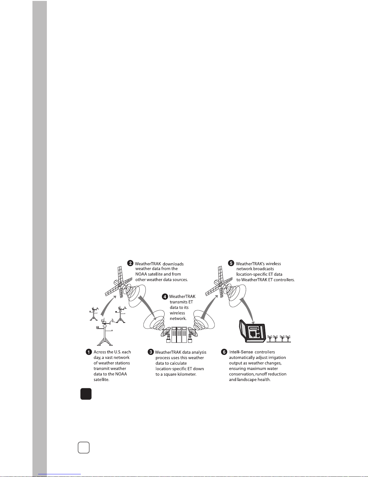
The Intelli-Sense Controller Solution
2
based ET updates via a two-way wireless communication network.
more than 14,000 weather stations, including the National Oceanic and
Atmospheric Administration (NOAA) network. Proven scientific modeling
validates local weather to less than one-half square mile before the data
is transmitted to the Intelli-Sense controller.
The WeatherTRAK ET Everywhere service delivers current weather-
The Intelli-Sense controller solution includes:
• WeatherTRAK‘s exclusive irrigation scheduling engine software
• WeatherTRAK ET Everywhere service*
• Toro and WeatherTRAK customer support
Irrigation Scheduling Engine
Intelli-Sense features WeatherTRAK’s fully-integrated scheduling engine
software that takes the guesswork out of irrigation system programming.
The scheduling engine automatically generates an accurate irrigation
program for each station based on specific landscape details such as plant
type, soil composition, slope and the type of sprinkler used. With the
Intelli-Sense controller solution, your entire landscape recieves pricisely
the water it needs to establish and maintain optimal plant health.
WeatherTRAK ET Everywhere Service*
WeatherTRAK‘s patented ET update service collects weather data from
!
Important:
The WeatherTRAK ET Everywhere subscription service is not included
with the purchase of the Intelli-Sense controller. For service setup and
subscription information, contact WeatherTRAK customer support at
1-800-362-8774.
Page 7

1
Thoroughly inspect the entire irrigation system to ensure
that all sprinklers and valves are working properly and that
the water supply is sufficient to operate each sprinkler zone
at optimum efficiency.
Install the controller per the installation instructions provided
on pages 71–75.
The following checklist provides the basic recommended steps
to guide you through the setup, programming and operation of
your Intellli-Sense TIS-240 controller:
Chapter 1
3
Take some time to read through this manual to become
familiar with the various controller components, programming steps, installation procedures, operating features and
controller capabilities.
Fill out the Irrigation System and Landscape Detail Worksheet.
provided. The information recorded on this worksheet will be
used for reference during the setup and programming process
as well as the (optional) WeatherTRAK ET Everywhere service
activation.
Set up and program your controller using the step-by-step
procedures beginning with “Controller Setup” on page 7..
(Optional) Activate the WeatherTRAK ET Everywhere
subscription service by calling 1-800-362-8774.
Controller Setup
Page 8
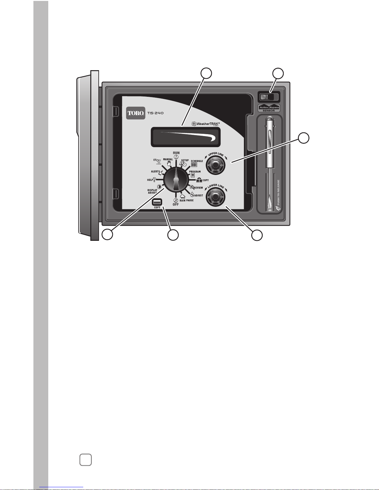
Control Panel Features
3 – Upper Line Knob
ct the various function menu items that appearelesotbonksihtnruT
on the upper line of the display.
4 – Lower Line Knob
Turn this knob left or right to change or set the value shown on the
lower line of the display.
5 – COPY Button
Use this button to copy the station settings from one station to another.
The COPY button is also used to clear various Alert conditions.
1 – LCD Display
Large easy-to-read digital display provides text information for
controller setup, programming, operation and messaging functions.
2 – Sensor Bypass Switch
Provides convenient bypass control of an (optional) Rain Sensor.
6 – Function Selector Knob
Turn this knob in either direction to select one of 14 main functions
as described on page 5.
4
1
2
3
4
5
6
Page 9
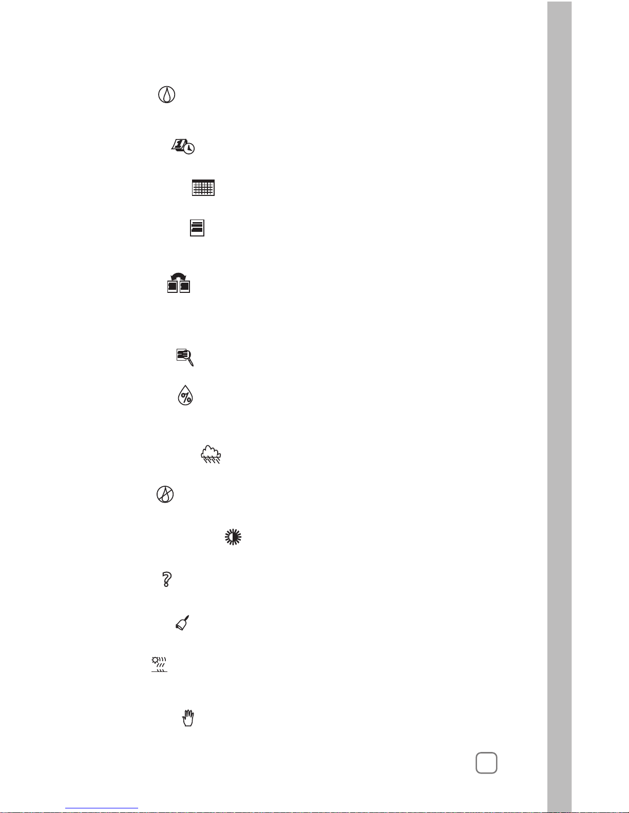
RUN
The normal dial position for automatic operation. Current time/date
and controller activity is displayed.
SETUP
To select and define specific controller setup parameters.
SCHEDULE
To set up and adjust the watering day schedules.
PROGRAM
To enter specific watering program information required for each
station.
COPY
To transfer programming data from one station to another. Also
used in combination with other functions to turn off alarm and reset
controller to default settings.
REVIEW
To review watering program information for each station.
ADJUST
To adjust station watering by 5% increase or decrease of run time
and/or watering days.
RAIN PAUSE
To suspend automatic watering for a period of 1 to 14 days.
OFF
To terminate and suspend all watering activity.
DISPLAY ADJUST
To increase or decrease display contrast.
HELP
To access Help Menu.
ALARM
To indicate system problems and operational conflicts.
ET
To display current daily and average weekly ET values and adjust
plant coefficient (Kc) value (if applicable).
MANUAL
To manually control station watering operations.
5
Page 10

6
1
2
3
4
6
5
1 – Safety Fuse
Replaceable 2.0A (slo-blo) fuse provides protection from short-circuit
condition on the 24 VAC circuitry.
2 – Sensor Connection Terminals
For connection of (optional) Rain Sensor control wires.
3 – Main Power Connection Terminals
For connection of 120 VAC hot, neutral and equipment ground wires.
4 – Common Wire Connection Terminals
For connection of 24 VAC irrigation control valve and auxiliary
common wires.
5 – Station Valve Wire Connection Terminals
For connection of 24 VAC irrigation control valve power wires.
6 – Master Valve/Pump Start Relay Wire Connection Terminal
For connection of 24 VAC auxiliary pump start relay or master
irrigation control valve power wire.
Note: The illustration below shows inside cover panel removed
for clarity.
Internal Controller Features
Page 11
Controller Setup
•
• Setting the Time Zone
• Selecting Auto Daylight Savings
• Setting the Active Station Count
• Selecting the Master Valve Control Option
• Selecting the Stacking Option
• Setting the Water District Number
• Setting the ET Zone Number
• Setting the Maximum Backup ET Value
• Setting the ZIP Code.
7
About Controller Input
As you begin the controller setup procedures, you will find that
virtually all controller input is accomplished in the same manner
using the Function Selector, Upper Line and Lower Line knobs.
For example, when you turn the Function Selector knob to the
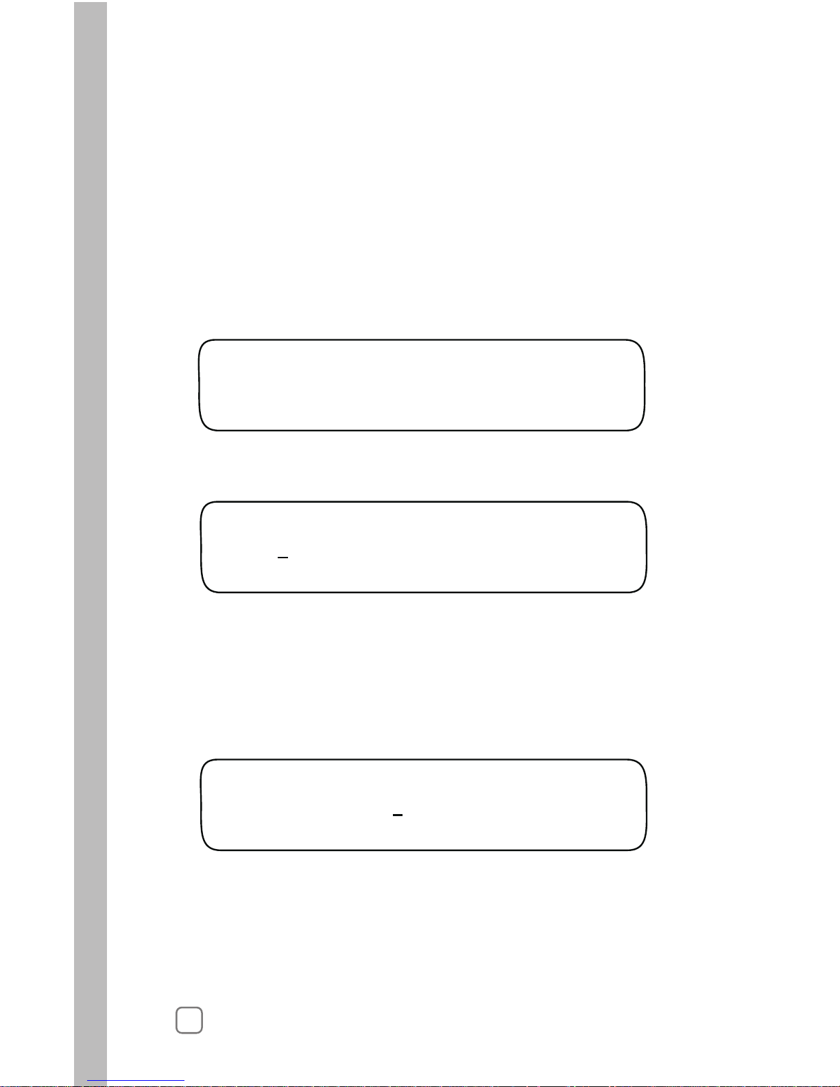
SETUP position, the first item in the Setup menu will appear
on the upper line of the display. In this case, Set Clock Year will
be displayed. The Year currently in memory will be displayed
on the lower Line as shown in the following example:
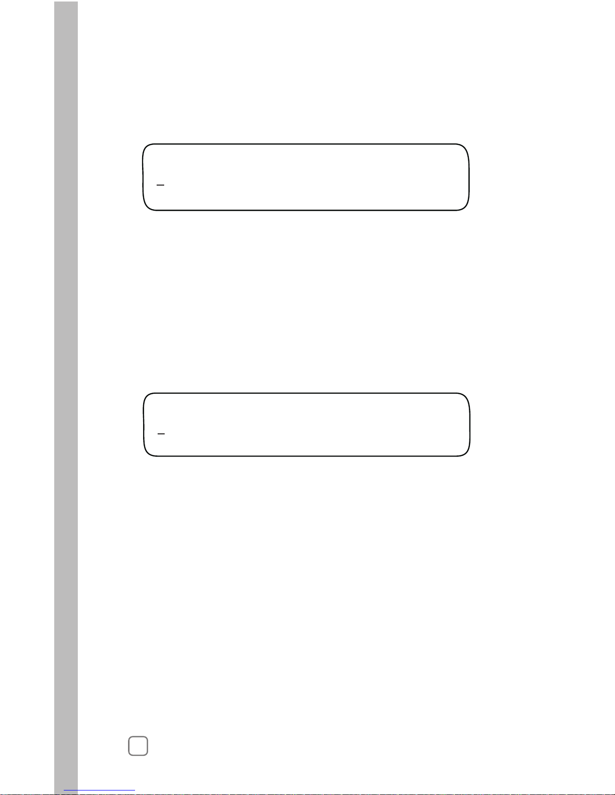
SET CLOCK (YEAR)
Sep 25 2006
MENU COMPLETE
Turning the Upper Line knob steps through the various Setup
menu items (Year, Month, Day, Hour, Minute, Time Zone, etc.).
Turning the Lower Line knob changes the value of the selected
menu item. Any value selection or change you make is entered
into the controller memory when the Upper Line or Function
Selector knob is turned.
A display prompt, similar the example below, lets you know
when you have reached the end of the selected function’s menu.
The information entered in the Setup function will adapt the
controller for operation in your location.
The Setup menu consists of the following items:
Setting the Clock
Page 12

Setting the Clock
1. Turn the Function Selector knob to SETUP. The first Setup menu
item is Set Clock (Year).
2. Turn the Lower Line knob to set the current year.
3. Turn the Upper Line knob one click to the right to select
4. Turn the Lower Line knob to set the current month.
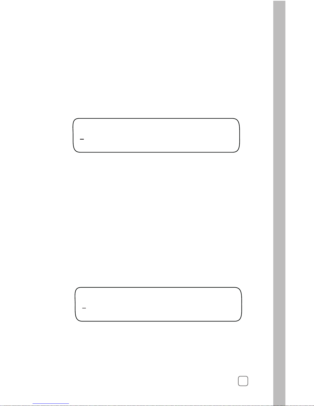
SET CLOCK (YEAR)
Feb 24 2006
8
the next Setup menu item, Set Clock (Month).
5. Turn the Upper Line knob one click to the right to select
6. Turn the Lower Line knob to set the current day.
Set Clock (Day).
7. Turn the Upper Line knob one click to the right to select
8. Turn the Lower Line knob to set the current hour (am or pm).
Set Clock (Hour).
9. Turn the Upper Line knob one click to the right to select
10. Turn the Lower Line knob to set the current minute.
Set Clock (Minute).
Note: Leave the Function Selector knob in the SETUP position
to continue selecting and setting the remaining Setup menu items.
Page 13

1. Within the Setup menu, turn the Upper Line knob to view the
following display:
2. Turn the Lower Line knob to select your time zone from the
following choices:
• Pacific (default setting)
• Alaska
• Hawaii
• Atlantic
• Eastern
• Central
• Mountain
Selecting Auto Daylight Savings
1. W
The default selection is Yes which enables the controller to
automatically compensate for Daylight Savings time. To disable
this option, turn the Lower Line knob to display No.
ithin the Setup menu , turn the Upper Line knob to view the
following display:
2.
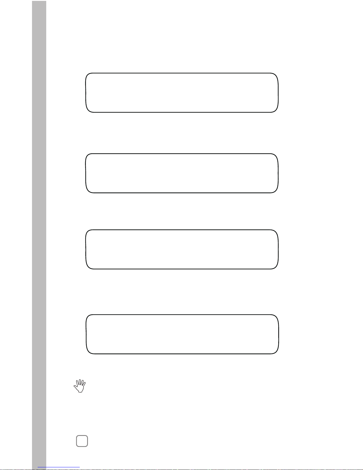
AUTO DAYLIGHT SAVINGS?
Yes
SET TIME ZONE
Pacific
9
Setting the Time Zone
Page 14
1.
2.
The default value is 24 stations. To change the number of active
Within the Setup menu, turn the Upper Line knob to view the
following display:
stations, turn the Lower Line knob.
Selecting the Master Valve Control Option
1. W
By default, the Master Valve circuit is Enabled. To disable the
circuit, turn the Lower Line knob to select Disabled.
itihin the Setup menu, turn the Upper Line knob to view the
following display:
2.
Note: The active station count entered in this step will also determine the
number of stations that can be accessed within the Programming, Review
and Copy function procedures.
Operation of the Master Valve (MV) control circuit can be enabled
or disabled as needed. By default the MV circuit is enabled.
SET MASTER VALVE
Enabled
10
SET ACTIVE STATIONS
24 (MAX AVAILABLE=24)
Setting the Active Station Count
The actual number of stations being used for irrigation must be entered
to enable accurate automatic scheduleing. By default, 24 stations are used
in the scheduling computations.
Important:
than actual will add unnecessary time to the Water Window causing an
alert condition to occur. Setting the station count lower than actual will
prevent some stations from operating.
!
If the actual number of active stations is not entered, errors and low
controller performace can result. Setting the active station count higher
MV
Page 15

1. Within the Setup menu, turn the Upper Line knob to view the
following display:
2.
STACKING
YES SCH A Same Times
11
Selecting the Stacking Option
YES is selected by default. To disable the Stacking option,
turn the Lower Line knob to select NO.
When the Stacking YES option is selected, the controller will be
constrained to operate one station at a time. The Water Window
start time and duration selected for Automatic Schedule A will
also be assigned to Automatic Schedule B and U (User-defined)
Before selecting Stacking NO, ensure that the irrigation system
hydraulic capacity and the controller’s maximum current draw
capacity (1.25A) will not be exceeded if four stations and master
valve circuit are operated concurrently.
Important:
!
STOP
When the Stacking NO option is selected, the constraint is removed,
allowing up to four stations to operate at the same time. A separate
Water Window start time and duration can be set for all schedules.
This completes the Setup procedures required for controller operation.
The additional procedures on pages 12 and 13 are used exlcusively for
operation with the ET Everywhere service. If you elect to use the
subscription service, you will be guided through these procedures by
a WeatherTRAK customer support representative at the time of service
activation.
Continue now to Chapter 3 - Setting Up Watering Schedules, begining
on page 15.
schedules.
Page 16
1. Within the Setup menu, turn the Upper Line knob to view the
following display:
3. T
2. The underlined digit is selected. To select a different digit, turn the
Upper Line knob.
urn the Lower Line knob to select a value from 0 – 9 for the selected
digit of the five-digit number.
4. Repeat steps 2 and 3 to display the Water District number.
SET WATER DIST.# Digit 1
12345
12
Setting the Water District Number
1. Within the Setup menu, turn the Upper Line knob to view the
following display:
SET ET ZONE# Digit 1
12345
Setting the ET Zone Number
3. T
2. The underlined digit is selected. To select a different digit, turn the
Upper Line knob.
urn the Lower Line knob to select a value from 0 – 9 for the selected
digit of the five-digit number.
4. Repeat steps 2 and 3 to display the ET Zone number.
Page 17
Setting the Maximum Backup ET Value
Setting the ZIP Code
1. Within the Setup menu, turn the Upper Line knob to view the
following display:
Turn the Lower Line knob to adjust the decimal number value.
3. Turn the Lower Line knob to adjust the digit from 0 – 9.
4. Repeat steps 2 and 3 to set the five-digit ZIP Code number.
MAX BACKUP ET Part 1
2.00
13
SET ZIP CODE Digit 1
12345
The Maximum Backup ET value is a failsafe measure used by the
controller to calculate daily watering requirments in the event that
current ET Everywhere data is not recieved for an extended period.
1. Within the Setup menu, turn the Upper Line knob to view the
following display:
2. The underlined digit is selected. To select a different digit, turn
the Upper Line knob.
2.
The Maximum Backup ET default value of 2.00 is automatically
calibrated to compensate for seasonal weather changes.
The whole number of the Maximum Backup ET value is selected
by default. To adjust the value from 1 – 3, turn the Lower Line
knob.
Note: The Maximum Backup ET is adjustable from 0.50 – 3.99.
The whole number is only adjustable to 0 when the decimal
number value is .50 or higher.
4.
Turn the Upper Line knob right one stop to select the decimal
number.
3.
Page 18

14
Notes
Page 19

3
Chapter 3
15
Setting Up Watering Schedules
A key component of a station operating program is its watering
schedule. Two optional scheduling modes are available: Automatic
and User-defined. Within the Automatic mode, two separate
schedules (A and B) can be defined. Within the User-defined (U)
schedule mode, operation with and without ET data input can be
defined. The defined watering schedules will then be assigned to
each station within the Program fucntion.
The Schedule function menu for Automatic and User-defined
schedules consists of the following items:
1. Turn the Function Selector knob to SCHEDULE to view the
following display:
2. Automatic Schedule A is selected by default. To select Schedule
B or U, turn the Lower Line knob.
SET SCHEDULE
Sch A
•
•
Set Schedule – to select the Schedule mode
Set Irrigation Start – to set the Water Window start time
Set Window Hour – to set the Water Window duration.
Automatic schedules A and B are defined with two additional
menu items:
•
Set High ET Start - to set start time for high ET conditions
•
Select Water Days - to set the active watering day schedule.
•
Selecting the Schedule Mode to Define
Setting the Water Window
Automatic and User-defined modes both require a Water Window
start time and duration to be defined.
When the STACKING YES option is selected within the Setup
menu, the Water Window defined for Schedule A will also apply
to Schedules B and U.
When the STACKING NO option is selected, a separate Water
Window can be defined for Schedules A, B and U.
Important:
!
The Water Window establishes the portion of an active watering
day in which all stations must complete their watering cycles.
Note: The watering day schedule for the User-defined mode is
defined in the Program function.
Page 20
1.
Within the Schedule menu, turn the Upper Line knob to view
the following display:
2. The default Water Window start time is 3:01 a.m. Turn the
Lower Line
knob to adjust the hour digit(s) and a.m./p.m.
SET IRR START HOUR SCH A
03:01am
16
3. Turn the Upper Line knob right one stop to view the following
display:
4. Turn the Lower Line knob to adjust the minutes digits.
SET IRR START MIN SCH A
03:01am
5. Turn the Upper Line knob right one stop to view the following
display:
6. Turn the Lower Line knob to adjust the Water Window duration
from 6 – 23 hours.
SET WINDOW HOUR SCH A
23:00 hrs (End 11:01pm)
7.8.Turn the Upper Line knob right one stop to view the following
display:
Turn the Lower Line knob to adjust the minutes of duration
from 01 – 59. End time is automatically calculated.
SET WINDOW MIN SCH A
23:00 hrs (End 11:01pm)
STOP: This completes the User-defined Schedule setup procedure.
Continue on page 29 to complete User-defined station programming.
For Automatic Schedule setup, continue on page 17.
Page 21

17
Setting the High ET Start Time
During periods of higher than normal ET rate, additional watering
may be needed to maintain the required soil moisture content,
as is typical for shallow-rooted turf during summer months. The start
time of this additional watering cycle is set by the High ET Start Time.
1.
2. The High ET Start default time is 1:00 p.m. To adjust the hour,
Within the Schedule menu, turn the Upper Line knob
to view the following display:
turn the Lower Line knob.
SET HiET START HR SCH A
01:00pm
Note: The High ET Start Time can only be set in p.m. hours.
3. Turn the Upper Line knob right one stop to view the following
display:
4. To adjust the minutes, turn the Lower Line knob to set 01 – 59
minutes.
SET HiET START MIN SCH A
01:00pm
Selecting a Watering Day Schedule
Active watering day schedule can be selected using one of the
following scheduling methods:
• Set By WeatherTRAK - Watering days selected per current
ET data supplied by the WeatherTRAK ET Everywhere service.
• Days-of-Week - Specified days of the week for each month.
• Odd/Even - All odd- or all even-numbered days.
• Interval - Active days based on a recurrent interval ranging from
01 (every day) to 31 (every 31st day).
1.
SELECT WATER DAYS SCH A
Set by WeatherTRAK(Dflt)
Within the Schedule menu, turn the Upper Line to view the
following display:
Page 22

18
NON-WATER DAY SCH A
None
3.
Turn the Upper Line knob right one stop to view the following
display:
4.
1.
The defalt setting for a Non-Watering Day is None. To prevent
watering on a specific day of the week, turn the Lower Line knob
to display the day abbreviation.
Note: This completes the setup procedure for an watering Automatic
schedule. To set up another watering schedule, repeat the setup procedure
starting on page 15.
Setting an Odd/Even Day Schedule
Within the Select Water Days menu, turn the Upper Line knob to view
the following display:
2.
An Odd numbered watering day schedule is selected by default.
To select Even, turn the Lower Line knob.
Note: When an Odd day schedule is used, two consecutive watering days
will occur at the end of all months with 31 days.
WATER DAY ODD/EVEN SCH A
Odd
This watering day schedule option enables all odd-or all even-numbered days
to be set as active watering days.
2.
The Set by WeatherTRAK option is selected by default. To use
this scheduling method, contunue at step 3 below. To select an
alternate scheduling method, turn the Lower Line knob to display
the desired option, then continue as noted:
• Odd/Even Days – below
• Interval – page 19
•
Days-of-Week – page 19
Page 23
19
Sun Mon Tue Wed Thu Fri Sat
Jan.
Feb.
March
April
May
June
July
Aug.
Sept.
Oct.
Nov.
Dec.
Y Y Y Y Y Y Y
Y Y Y Y Y Y Y
Y Y Y Y Y Y Y
Y Y Y Y Y Y Y
Y Y Y Y Y Y Y
Y Y Y Y Y Y Y
Y Y Y Y Y Y Y
Y Y Y Y Y Y Y
Y Y Y Y Y Y Y
Y Y Y Y Y Y Y
Y Y Y Y Y Y Y
Y Y Y Y Y Y Y
Watering Days for Automatic Schedule Date
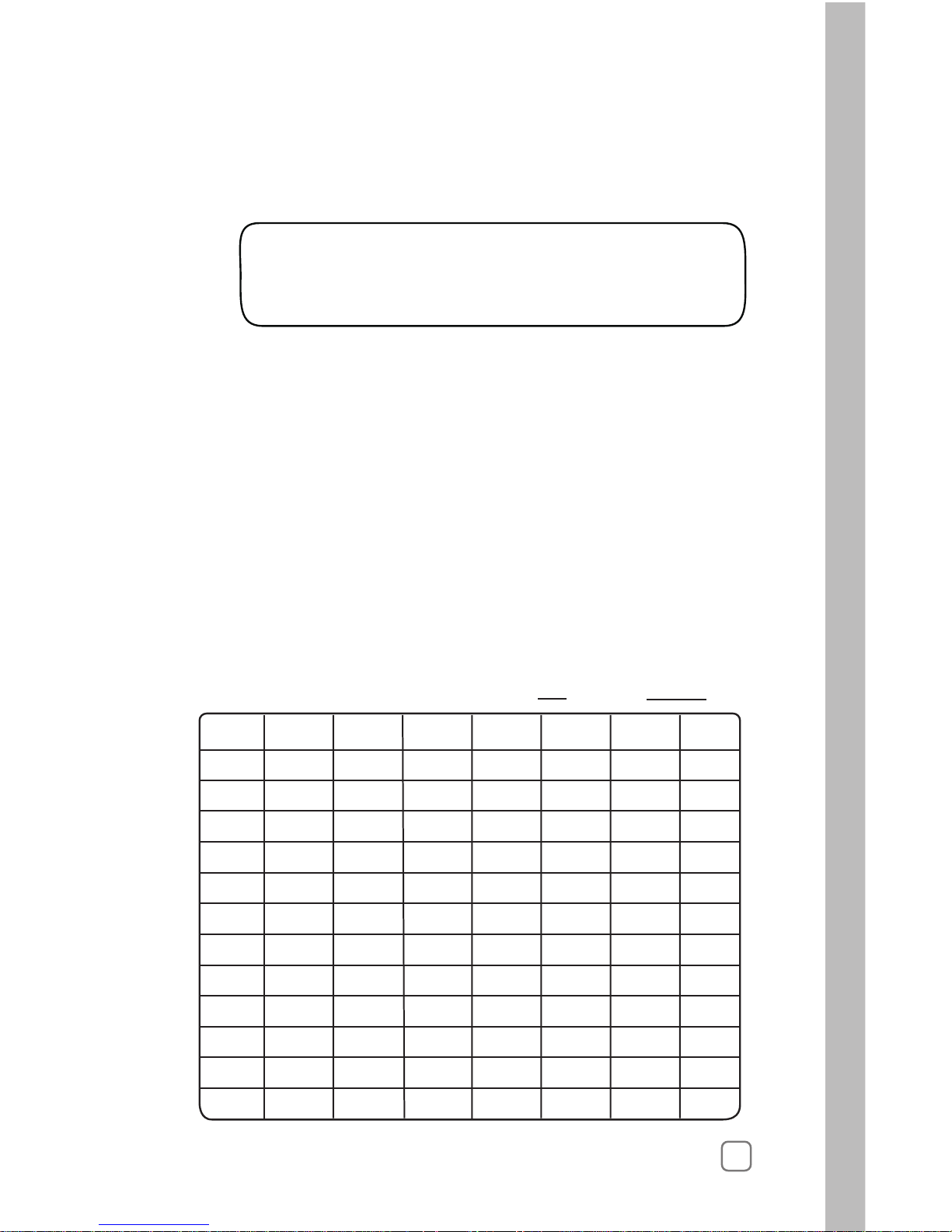
Setting a Days-of-Week Schedule
This scheduling option enables each day of the week (per month) to be
selected to water as needed.
The chart below is provided to help visualize this type of schedule and
to use for reference when entering the schedule.
All days are set as active by default, indicated by the Y (Yes) in each
square. To use this chart, place a dash in each square to indicate the
days to be excluded from the active day schedule.
WATER DAY INTERVAL SCH A
01 Day (water every day)
1.
Setting an Interval Day Schedule
Within the Set Water Days menu, turn the Upper Line knob to
view the following display:
2. The default Interval is 01 which schedules every day as active.
To select an Interval from 02 – 31, turn the Lower Line knob.
Note: The current day is the first active day of the interval
schedule. For example, if today is Saturday and a 02 interval
(water every-other-day) is set, today would be active. The next
active watering day is Monday.
Page 24
20
Note: Moving the underline past Saturday will advance the display
to the next month in sequence.
Turn the Upper Line knob to the right to display day schedule
2.
Jan S M T W T F S SCH A
Y Y Y Y Y – Y
3.
To remove a day from the schedule, turn the Upper Line knob
to select (underline) the day.
4.
5.
Turn the Lower Line knob to replace the Y with a dash (–). In the
Jan S M T W T F S SCH A
Y Y Y Y Y
YY
Repeat steps 2 – 4 for all remaining months.
example below all Fridays in January are excluded for Schedule A.
per month.
1.
SELECT WATER DAYS SCH A
Days of Week
Within the Select Water Days menu, turn the Lower Line knob
to view the following display:
Note: When the Intelli-Sense is operating in an ET-controlled mode,
it will attempt to run irrigation on all active days as needed. During
months of low ET rate, some active days may be skipped. While in
the summer months, with generally high ET rate, every active day
may be needed to provide the required amount of irrigation. If too
many days are excluded from the schedule to enable the required
irrigation to occur, a Day Pattern Alert condition will result.
See “Day Pattern Alert” on page 56 for additional information.
Page 25

4
Chapter 4
21
Setting Up Station Programs
Set Schedule
•
Use Water Window
•
Select Srinkler Type
•
Precipitation Rate*
•
Sprinkler Efficiency*
•
Select Soil Type
•
Select Plant Type
•
Set Root Depth*
•
Set Microclimate
•
Set Slope Factor
•
Set Sprinkler Location
•
Set Usable Rainfall
•
Within the Schedule function, watering schedules were set up
for Automatic and/or User-defined operation. Now, within the
Program function, the remaining setup requirements for controller
operation are completed.
Note: To complete the station programming procedures for
Automatic operation, continue on this page.
For User-defined station programming, continue on page 29.
Automatic Station Programming
When a station is programmed for automatic operation, the
controller calculates a baseline irrigation program suited to the
specific irrigation system and landscape parameters selected.
If the ET Everywhere service is activated, current ET data is
downloaded to the controller each night, providing the real-time
information needed by the controller to recalculate and optimize
baseline watering program for the next scheduled watering day.
The Program menu items required to complete an Automatic
watering program are as follows:
As you can see by this list, many factors are required by the
controller’scheduling engine to formulate an accurate baseline
watering schedule. To make the setup process as easy as possible,
the Intelli-Sense is ready to make some of the decisions for you.
The items listed with an asterisk (*) have default values entered
automatically based on selections made in preceding steps.
Page 26
Selecting the Station to Program
1.
Turn the Function Selector knob to PROGRAM to view the
following display:
2.
2.
Station 1 is automatically selected. To change the station number,
turn the Lower Line knob.
Note: The number of active stations defined in the Setup function,
determines the number of stations that can be selected.
SET STA TO PROGRAM
STA 01
Selecting the Program Mode
1. W
The Fully Automated mode is selected by default. If it is not
displayed, turn the Lower Line knob to select this mode.
ithin the Program menu, turn the Upper Line knob to view
the following display:
SET PROGRAM MODE STA 01
Fully Automated Sch A
Automatic Schedule A is selected by default. To select Automatic
Schedule B, turn the Lower Line knob.
Selecting the Program Schedule
1. Within the PROGRAM menu, turn the Upper Line knob to view
the following display:
SET SCHEDULE STA 01
Sch A
2.
22
Page 27

23
The Yes option (use Water Window) is selected by default.
The Water Window end time displayed corresponds to the
Water Window parameters set in the Schedule function.
To disable Water Window for the selected station, turn the
Lower Line knob to select the No option.
Selecting the Water Window Option
2.
USE WATER WINDOW STA 01
Yes (end time 03:00)
Selecting the Sprinkler Type
1. Within the Program menu, turn the Upper Line knob to view
the following display:
1. Within the Program menu, turn the Upper Line knob to view
the following display:
2. Turn the Lower Line knob to select one of the following
sprinkler types:
• Spray Head
• Full Circle Rotor
• Part Circle Rotor
• Mixed Rotors
• Full Circle Impact
• Part Circle Impact
• Mixed Impacts
• Stream Rotors
• Bubbler
• Drip Emitter
• Stream Spray
SET SPRINKLR TYPE STA 01
Spray Head
Page 28

2
4
Setting the Precipitation Rate
1. Within the Program menu, turn the Upper Line knob to view
the following display:
2. The default PR value will be displayed for the sprinkler type
selected. The whole number is selected by default. Turn the
Lower Line knob to adjust the value from 0 – 9.
PRECIP PART 1 STA 01
1.70 Inches/Hr (default)
!
Important:
Note: For additional information regarding PR value calulation
methods, see “Gathering Site Data” on page 79.
The sprinkler precipitation rate (PR) is a key factor in the calculation of an automatic watering program. If you know the actual
PR value, enter it at this time. If you do not have this information,
a default value, based on the sprinkler type entered in the
previous step, will be automatically entered by the controller.
Setting the Efficiency Value
• Increasing the Efficiency value (sprinkler efficiency is higher
than normal) decreases overall watering.
• Decreasing the Efficiency value (sprinkler efficiency is lower
than normal) increases overall watering.
Like the sprinkler’s PR, the Efficiency value is a key factor required
by the controller’s scheduling engine to calculate an efficient watering
program for each station. The controller will automatically enter an
Efficiency value based on the type of sprinkler selected for the station.
4.
Turn the Lower Line knob to adjust the decimal number value.
3. Turn the Upper Line knob right one stop to select the decimal
number.
Note: The PR value is adjustable from 0.10 – 9.90. The whole
number value is only adjustable to 0 when the decimal number
value is .10 or higher.
Changing the Efficiency value will alter overall station watering
operation as follows:
Page 29

25
1. Within the Progam menu, turn the Upper Line knob to view
the following display:
The default Efficiency value is displayed for the sprinkler type
selected. To change the value, turn the Lower Line knob to
adjust the value from 10 – 95%.
2.
SPKLR EFFICIENCY
STA 01
70 Percent (default)
The default Soil type is Sandy. To change the Soil type, turn the
Lower Line knob to select from the following choices:
2.
• Sandy Loam (more sand than clay)
• Loam (equal proportion of sand and clay)
• Clay Loam (more clay than sand)
• Clay
SET SOIL TYPE STA 01
Sandy
Selecting the Plant Type
2.
• Cool SeasonTurf
• Warm SeasonTurf
• CombinedTurf
• Flowers
• Trees
• Shrubs - High Water Use
• Shrubs - Medium Water Use
• Shrubs - Low Water Use
• Mixed - High Water Use
• Mixed - Medium Water Use
• Mixed - Low Water Use
• Native Shrubs/ Trees
• Native Grasses
• Custom Plant A
• Custom Plant B
• Custom Turf
SET PLANT TYPE STA 01
Cool Season Turf
Selecting the Soil Type
The default Plant type is Cool Season Turf. To change the Plant
type turn the Lower Line knob to select from the following choices:
1. Within the Progam menu, turn the Upper Line knob to view
the following display:
1. Within the Progam menu, turn the Upper Line knob to view
the following display:
Page 30

26
Setting the Root Depth
1. Within the Program menu, turn the Upper Line knob to view
the following display:
Note:
Increasing
the root depth increases overall watering.
Decreasing the root depth decreases overall watering.
SET ROOT DEPTH STA 01
06 Inches (default)
2. The default root depth will be displayed for the soil type and
plant type previously selected. To change the depth, turn the
Lower Line knob adjust from 2 – 36 inches.
•
2. Sunny All Day is selected by default. To select one of the alternate
Microclimate descriptions, turn the Lower Line knob.
SET MICROCLIMATE STA 01
Sunny All Day
Selecting the Microclimate
The Microclimate is basically the amount of sunlight and shade covering
ofthe station’s watering area. Select the Microclimate that best describes
the station from the following options:
1. Within the PROGRAM menu, turn the Upper Line knob to
view the following display:
Sunny All Day = Sun for 7 to 8 hours per day, no change to
calculated ET rate.
•
Sunny Most of the Day = Sun for 4 to 6 hours per day;
decreases watering by 10% of calculated ET rate.
•
Shady Most of the Day = Shady for 4 to 6 hours per day;
decreases watering by 20% of calculatd ET rate.
•
Shady Most of the Day = Shady for 4 to 6 hours per day;
decreases watering by 30% of calculated ET rate.
Page 31

Selecting the Slope Factor
1.
2.
2.
Within the PROGRAM menu, turn the Upper Line knob to view
the following display:
• 6 – 8% Grade
• Mild 9 – 12% Grade
Gentle
• Moderate 13 – 20% Grade
• Steep>20% Grade
SET SLOPE FACTOR STA 01
None/Slight 0-5% Grade
27
The Slope factor is used in the automatic program calculation to
determine the watering run time and number of repeat cycles per
watering day.
None/ Slight (0 –5%) grade is selected by default. To select
an alternate Slope factor, turn the Lower Line knob to display
one of the following options:
A Slope factor of 0 – 5% is not factored in the watering program
calculation.
Selecting the Sprinkler Location (on slope)
1. Within the Program menu, turn the Upper Line knob to view
the following display:
• All Parts of Slope (default if Slope is other than None)
• Top of Slope
• Middle of Slope
• Bottom of Slope
Note: If the Slope factor selected is None/Slight, sprinkler location is
not factored and cannot be changed from the default setting.
SPRINKLR LOCATION STA 01
None, No Slope Set
None, No Slope Set is selected by default. To choose an
alternate Sprinkler Location, turn the Lower Line knob
to select one of the following options:
Increasing the Slope factor beyond 5% will result in decreasing
the watering run time per cycle and increasing the number of
watering cycles per day.
Page 32

Selecting the Usable Rainfall
1. Within the Program menu, turn the Upper Line knob to view
the following display:
The amount of watered area not restricted from rainfall determines
the Usable Rainfall setting of 100% or None. For example, a planter
that is blocked from rainfall by a roof overhang would have a
Usable Rainfall value of None. An open lawn area with no obstructions
would be 100%.
Note: When None is selected, the station will continue to operate during
Note: The additional percentage factors (25%, 50% and 75%)
displayed between None and 100% apply to systems utilizing
the optional WeathTRAK Rain Service.
a watering hold condition initiated by Rain Pause or an active Rain Sensor.
USABLE RAINFALL STA 01
100%
28
Completing Automatic Programming
1. Within the Program menu, turn the Upper Line knob to view
the following display:
Important:
If there are other stations remaining to be programmed that will use
the same or similar program set up, the COPY function can be used to
transfer the complete program setup information from one station to
another or to all stations at the same time. Minor program changes to
individual stations can then be made quickly, greatly reducing the time
involved in programming 24 stations.
See “Using the Copy Function” on page 38 for detailed information.
2. T
Repeat the programming process for each station as needed.
The next station number in sequence will be selected. To select a
different station number, turn the Lower Line knob.
urn the Upper Line knob to continue programming the stations.
3.
PROGRAM COMPLETE STA 01
!
2. 100% is select by default. To adjust the value to None, turn
the Lower Line knob.
Page 33

29
Within the User-defined programming mode are two format options:
User-With ET and User-No ET. Both formats require the same basic
setup process, with the exception that User-With ET mode enables a
Reference ET value to be selected.
A baseline watering program is established for the station using the
following User-defined setup parameters:
• Water Window Option
• Cycle Time
• Number of Cycles per day
• Soak Time
• Watering Day Schedule
• Reference ET (User-With ET format only)
User-defined Station Programming
Select the Station to Program
1.
Turn the Function Selector knob to PROGRAM to view
the following display:
2.
Station 1 is automatically selected. To change the station number,
turn the Lower Line knob.
Note: The number of active stations defined in the Setup function,
determines the number of stations that can be selected.
SET STA TO PROGRAM
STA 01
When the User - With ET option is used, the station’s baseline watering
progam is updated daily by the ET Everywhere service and adjusted
automatically to suit current ET conditions.
When the User - No ET option is used, the station’s watering progam
remains constant, without regard to changes in ET rate.
Page 34

30
The Use Water Window- YES option is selected by default. To
select NO, turn the Lower Line knob.
1. Within the Program menu, turn the Upper Line knob to view
the following display:
USE WATER WINDOW STA 01
YES (end time 11:01pm)
2.
2.
Selecting the Program Mode
Selecting the Water Window Option
The station Cycle time is set to 05.0 minutes by default. To adjust the
cycle time minutes digit(s) from 00 – 99, turn the Lower Line knob.
Note: Adjusting the Cycle time to 00 will disable the station from
automatic operation.
SET CYCLE TIME STA 01
05.0 Minutes
2.
Setting the Cycle Time
1. W
Fully Automated mode is selected by default. Turn the Lower Line
knob to select the User - With ET or User - No ET option as shown
in the example below:
ithin
the following display:
the Program menu, turn the Upper Line knob to view
SET PROGRAM MODE STA 01
Fully Automated Sch A
SET PROGRAM MODE STA 01
User – With ET Sch U
1. Within
the following display:
the Program menu, turn the Upper Line knob to view
Page 35

31
The station Cycle time 10ths is set to 0 by default. To adjust the
cycle time 10ths digit from .0 – .9, turn the Lower Line knob
as shown in the example below.
3.
Turn the Upper Line knob right one stop to select the following
display:
SET CYCLE 10ths STA 01
12.0 Minutes
SET CYCLE 10ths STA 01
12.5 Minutes
4.
The number of watering cycles per active day is set to 1 by default.
To adjust the number from 0 – 20 cycles per day, turn the Lower
Line knob.
1. Within the Program menu, turn the Upper Line knob to view
the following display:
SET # OF CYCLES STA 1
01 Cycles/Operating Day
2.
Selecting the Number of Watering Cycles
Note: Adjusting the number of cycles per day to 00 will disable
the station from automatic operation.
Page 36

2.
Setting the Soak Time
1. Within the Progam menu, turn the Upper Line knob to view
the following display:
SET SOAK TIME STA 01
30 Minutes
32
The default Soak time is 30 minutes. To adjust the soak time from
00-480 minutes, turn the Lower Line knob.
Setting the Usable Rainfall
1. Within the Program menu, turn the Upper Line knob to view
the following display:
The amount of watered area not restricted from rainfall determines
the Usable Rainfall setting. For example, a planter next to the house
case, the None option should be selected. An exposed lawn area with
no obstructions would have the YES option selected.
Note: When the None option is selected, the station will continue to
operate as programmed during a watering delay period initiated by
the Rain Pause function or an active Rain Sensor.
USABLE RAINFALL STA 01
Yes
2. The Yes option is selected by default. To select None, turn the
Soak time is an adjustable delay period that is placed between station
watering cycles. The delay time enables irrigation water to soak into
the soil to avoid pooling, runoff and possible erosion.
Note: The Soak time entered is actually the minimum delay period.
The actual soak time may be longer due to programming variables
of other stations scheduled to operate on the same day.
Lower Line knob.
may be completely blocked from rain by the roof overhang. In this
Page 37

33
2.
1.
Within the PROGRAM menu, turn the Upper Line knob to view
the following display:
SELECT WATER DAYS STA 01
Everyday
Selecting a Watering Day Schedule
Active watering days can be selected for each station using one of
the following scheduling methods:
• Everyday - Every day of the year is active
• Set Days - Specific days of the week per month are active.
• Odd/Even - All odd- or even-numbered days are active
• Interval - Active days based on a recurrent interval from
01 (every day) to 31 (every 31st day).
The Everyday scheduling option is selected by default. To choose
an alternate scheduling method, turn the Lower Line knob.
Note: If the Everyday schedule is used, continue on page 36.
If the Odd/Even schedule is selected, continue below.
If the Interval schedule is selected, continue on page 34.
If a Set Days schedule is selected, continue on page 34.
1.
Setting an Odd/Even Day Schedule
Turn the Upper Line knob to view the following display:
2. An Odd day schedule is selected by default. To select an Even
day schedule, turn the Lower Line knob right one stop to view the
following display:
Continue on page 36.
WATER DAY ODD/EVEN STA01
Odd
3.
Even
WATER DAY ODD/EVEN STA01
Page 38

34
WATER DAY INTERVAL SCH A
01 Day (water every day)
1.
2.
Setting an Interval Day Schedule
Within the Set Water Days menu, turn the Upper Line knob to
view the following display:
Note: The current day is the first active day of the Interval schedule.
For example, if today is Saturday and a 02 (every-other-day) Interval
is set, today is active. The next active watering day is Monday.
Sun Mon Tue Wed Thu Fri Sat
Jan.
Feb.
March
April
May
June
July
Aug.
Sept.
Oct.
Nov.
Dec.
Y Y Y Y Y Y Y
Y Y Y Y Y Y Y
Y Y Y Y Y Y Y
Y Y Y Y Y Y Y
Y Y Y Y Y Y Y
Y Y Y Y Y Y Y
Y Y Y Y Y Y Y
Y Y Y Y Y Y Y
Y Y Y Y Y Y Y
Y Y Y Y Y Y Y
Y Y Y Y Y Y Y
Y Y Y Y Y Y Y
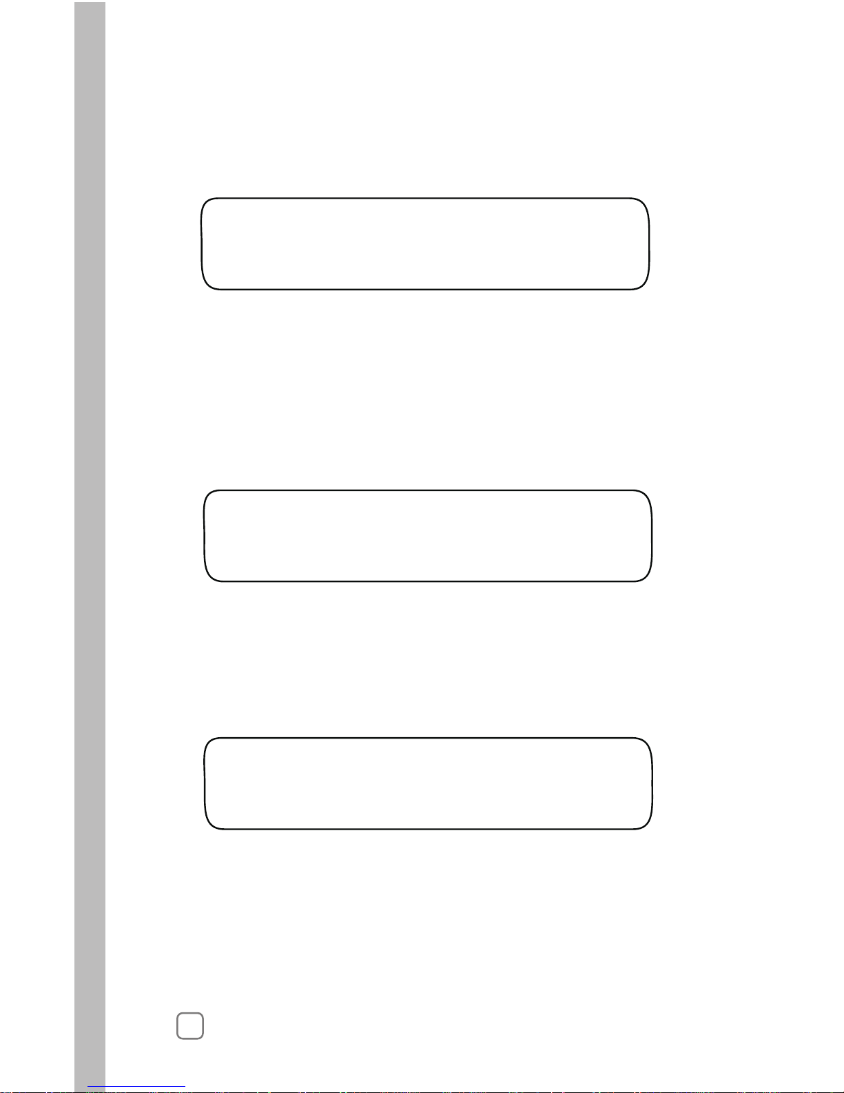
Setting a Days-of-Week Schedule
Station # Date
The chart below is provided to assist you in determining a weekly and
monthly watering day schedule prior to entering the information into
the station program. Make a copy of the table for each station that will
use a different Set Days schedule. All days are set as active by default,
to exclude from the schedule.
indicated by the Y in each box. Mark the box of each day that you want
The default Water Day Interval is 01 which schedules every day
as active. To change the Interval number from 02 – 31, turn the
Lower Line kob.
Page 39

35
2.
The Set Days scheduling option is selected by default. To select
an alternate scheduling method, turn the Lower Line knob.
Note: Moving the line past Saturday will advance the display
to the next month in sequence.
This completes the program setup process for the User-No ET
schedule format. To program additional stations, return to the
beginnning of Chapter 4 on page 21.
If a User-With ET schedule fomat is selected, continue on
.ssecorpputesehtetelpmocot63page
T
display:
Note: By default, all days of all months are active. The month of
January is displayed first. The letter Y below the day abbreviation
indicates the day is active.
urn the Upper Line knob to the right to select the following
3.
Jan S M T W T F S STA 01
Y Y Y Y Y Y Y
Jan S M T W T F S STA 01
Y Y Y Y Y – Y
4.
To remove a day from the schedule, place the line under the
appropriate day abbriviation by turning the Upper Line knob.
5.
6.
Turn the Lower Line knob to replace the Y with a dash (–).
Repeat steps 3, 4 and 5 for all remaining months.
In this example, Station 1 will water every day in January except
on Fridays.
1. Within the PROGRAM menu, turn the Upper Line knob to view
the following display:
SELECT WATER DAYS STA 01
Set Days
STOP:
Page 40

36
1.
Setting the Reference ET Value
Turn the Upper Line knob to view the following display:
By setting a Reference ET value based on the highest ET demand
period of the year, proper watering is ensured for the entire year.
REF. ET PART 1 STA 01
1.00 (Weekly ET 1.00)
5. Turn the Upper Line knob to view the following display:
REFERENCE MONTH STA 01
JUL (7 days/week)
6. Turn the Lower Line knob to change the month.
7. Turn the Upper Line knob to view the following display:
PROGRAM COMPLETE STA 01
This completes the program setup process for a User-With ET
schedule format. To program additional stations, return to the
beginnning of Chapter 4 on page 21.
STOP:
Note: If the selected station number uses the Set Days water
day schedule, Reference Month menu item will be accessable.
To adjust this setting, continue at step 5.
If the Set Days schedule is not used, continue at step 7.
1.
2. The whole number of the Reference ET value is selected by default.
To adjust the value from 1 – 3, turn the Lower Line knob.
4.
Turn the Lower Line knob to adjust the decimal number value.
3. Turn the Upper Line knob right one stop to select the decimal
number.
Note: The Reference ET value is adjustable from 0.50 – 3.99. The
whole number is only adjustable to 0 when the decimal number
value is .50 or higher.
Page 41

37
Control Functions
• COPY
• REVIEW
• ADJUST
• RAIN PAUSE
• OFF
• DISPLAY ADJUST
• HELP
• ALERTS
• ET
• MANUAL
• RUN
The Setup, Schedule and Program functions enable you to select
an automatic watering schedule designed specifically for your landscape.
The remaining Control Functions provide enhanced control capabilities
of your irrigation system, enabling you to perform various operations
such as information Copy, Review and watering program fine-tuning;
resolving actual and potential controller problems as well as Manual
watering operations.
Within this chapter you will find detailed instruction provided for
each of the Control Functions in the following order:
Page 42

Using the Copy Function
Copying Station Information
1. Turn the Function Selector knob to COPY to view the following
display:
2. Turn the Upper Line knob to select the source station number.
3. Turn the Lower Line knob to select the destination station number.
To select All Stations, turn the Lower Line knob one stop past the
highest station number, as shown in the following display:
COPY FROM STA 01
To STA 02 (Press COPY)
38
The Copy function provides a convenient method of transferring
all watering program information from one station to another or to
all active stations simultaniously. Minor changes can then be made to
each station individually as needed, greatly simplifing the process of
programming several stations with similar watering progam attributes.
The Copy function also serves as a means of quickly resetting all userdefined Setup, Schedule and Program settings back to the factory-default
values. The default values can be reapplied to selected stations or all
stations simultaniously as needed.
4. Press and hold the COPY button. Release the button when
COPYING DONE! is displayed.
COPY FROM STA 01
To ALL STA’s (Press COPY)
COPYING DONE!
Note: The number of active stations defined in the Setup function,
determines the number of stations that can be selected.
Page 43

39
Restoring Station PROGRAM Function Default Values
1. Turn the Function Selector knob to COPY to view the following
display:
2. Turn the Upper Line knob right one stop past the highest station
number to view the following display:
3. Turn the Lower Line knob to select the station number to be
restored.
To select All Stations, turn the Lower Line knob one stop past the
highest station number, to view the following display:
COPY FROM STA 01
To STA 02 (Press COPY)
Important:
Restoring the station Program default values erases all user-defined
values and settings for the selected station(s).
4.
5.
Press and hold the COPY button. Release the button when
COPYING DONE! is displayed.
COPY PROGRAM DEFAULTS
To STA 02 (Press COPY)
COPY PROGRAM DEFAULTS
To ALL STA’s (Press COPY)
COPYING DONE!
!
Note: The number of active stations defined in the Setup function,
determines the number of stations that can be selected.
Page 44

40
Restoring SCHEDULE Function Default Values
1. Turn the Function Selector knob to COPY to view the following
display:
2. Turn the Upper Line knob right one stop past Program Defaults
to view the following display:
COPY FROM STA 01
To STA 02 (Press COPY)
Important:
Restoring the controller Schedule default values erases all
user-defined values and settings within this function.
3. Press and hold the COPY button. Release the button when
COPYING DONE! is displayed.
COPY SCHEDULE DEFAULTS
(Press COPY)
COPYING DONE!
!
Note: The number of active stations defined in the Setup function,
determines the number of stations that can be selected.
Page 45

41
Restoring SETUP Function Default Values
1. Turn the Function Selector knob to COPY to view the following
display:
2. Turn the Upper Line knob right one stop past Schedule Defaults
to view the following display:
COPY FROM STA 01
To STA 02 (Press COPY)
Important:
Restoring the controller Setup default values erases all user-defined
values and settings within this function.
3. Press and hold the COPY button. Release the button when
COPYING DONE! is displayed.
COPY SETUP DEFAULTS
(Press COPY)
COPYING DONE!
!
Note: The number of active stations defined in the Setup function,
determines the number of stations that can be selected.
Page 46

42
Using the Review Function
The Review function provides a convenient, at-a -glance overview of
the watering progam values currently set for each active station. The
review information is displayed in an abbrevieated format that allows
virtually all current values and settings to viewed in one screen.
1.
The abbreviated data shown in the example above represents the
following watering program information currently set for Station 1:
(1) Station number 1 is assigned to watering Schedule A.
(2) The station will water for 11.9 minutes, one time per day.
(3) The station is assigned to the Automatic program mode.
(4) The active watering day schedule for Week 1 is Thursday.*
(5) The percentage Adjust factor is 0%.
(6) Soak time is set for 5 minutes.
*Note: The remainder of the 8-week watering day schedule can be
reviewed by turning the Lower Line knob.
ST01 A 11.9 MIN 01X AUTO
Wk1:-––T-– 0% Soak 5
Turn the Function Selector knob to REVIEW to view the following
display:
2.
Station 1 will be selected by default. To select a different station
to review, turn the Upper Line knob.
1 2 3
4 5 6
Additional review information can be acquired for each station by
pressing the COPY button while the Fucntion Selector knob is in the
PROGRAM position. To use this review option:
2.
Station 1 is selected by default. To select a different station
number to review, turn the Lower Line knob.
1.
Turn the Function Selector knob to PROGRAM to view the
following display:
SET STA TO PROGRAM
STA 01
Page 47

43
3.
Press and hold the COPY button. The station review information
wll be displayed similar to the following example:
STA 01-A AUTO Y sh 1.70
70 s cst 06 sua no a Y
1
3
52 4
6 7 1098
11 12
13
The abbreviated data shown in this example represents the following
watering program information currently set for Station 1 when set to
the Automatic program mode:
(1) Station number 1 is assigned to watering Schedule A.
(2) The station is assigned to the Automatic program mode.
(3) The Water Window option is selected (Yes).
(4) Sprinkler type selected is Spray Head (sh) .
(5) Precipitation rate value is set at 1.70.
(6) Sprinkler efficiency value is set at 70%.
(7) Soil type selected is Sandy.
(8) Plant material selected is Cool Season Turf.
(9) Root depth is set at 6 inches.
(10) Location is Sunny All Day.
(11) Slope factor is none.
(12) Sprinklers are located on All parts of the slope.
(13) Usable Rainfall option is Yes (% factor shown if less than 100%).
STA 01–U UwET Y Everyday
05.0 Min 01X Soak 30 Min
1 42 3
5 6
The review screen example below represents the watering program
information for Station 1 when set to a User program mode:
(1) Station number 1 is assigned to watering Schedule U.
(2) The station is assigned to the User with-ET program mode.
(3) The Water Window option is selected (Yes).
(4) The active watering day schedule is Everyday.
(5) The station will water for 5 minutes one time per day.
(6) Soak time is set for 30 minutes.
Page 48

Using the Adjust Function
44
1. Turn the Function Selector knob to ADJUST to view the
following default display:
2. Turn the Upper Line knob to select the desired station number.
3. Turn the Lower Line knob to change the percentage in
increments from +25 % to –50%.
For example, increase station 1 by 05%.
ADJ WATER AMOUNT STA 01
0% = NO CHANGE
ADJ WATER AMOUNT STA 01
+05% = More Water
ADJUST
Water Amount
The Adjust function provides a convenient method of fine-tuning
a station watering program to correct for over- or under-watering.
The sum watering program of any station can be easily adjusted
for a 25% increase or a 50% decrease in 5% increments. All
programnming factors that determine how long and how often
the station operates are instantly recalculated and adjusted.
Page 49

45
ST01 A 12.5 MIN 01X AUTO
Wk1:––––T–– +05% Soak 5
4.
The calculated program changes for the station will be displayed.
In this example, a +05% adjustment resulted in a Cycle time
increase from 11.9 minutes to 12.5 minutes.
Note: When an increase adjustment is made, the controller
automatically calculates a program solution that provides an
increase in watering without exceeding the soil’s capacity to
absorb and hold water (resulting in runoff). In the example
above, simply increasing the Cycle time provided the solution.
If an increase in Cycle time would exceed the runoff point,
a decrease in Cycle time accompanied by an increase in watering
frequency (either by increased active days or watering cycles
per day) could result.
Note: Using the Review function in conjunction with Adjust
function provides a convenient reference of actual station operating
values before and after the calculated adjustments.
Turn the Function Selector knob toREVIEW. The display will
show all current operating information for station 01.
Page 50

46
Adjust the Watering Frequeny (Automatic mode only)
Turn the Lower Line knob right one stop to view the following
display:
4. Turn the Lower Line knob to adjust the value from -30% to +30%.
The example below shows the display with station 1 increased 10%.
3. Turn the
Note: If the selected station number is assigned to a User program
mode, the following display will be shown:
Upper Line knob to select the desired station number.
ADJUST DAYS (MAD) STA 01
+10% = More Often (40%)
ADJUST DAYS (MAD) STA 01
0% = No Change (50%)
ADJUST DAYS (MAD) STA 06
Non-Adjustable Mode
Stations assigned to an Automatic program mode can be adjusted for
watering day frequency and depletion rate. For example, you may need
to water more often with new turf while the root depth is shallow. This
adjustment feature enables an increase or decrease in active watering days
using the Managed Allowable Depletion (MAD) value for reference.
The Day Frequency is adjustable from -30% – +30% in 5% increments.
The resulting MAD value ranges between 20% – 80% (50% = no change).
1. Turn the Function Selector knob to ADJUST to view the
following default display:
2.
Day Frequency/Depletion
ADJUST
ADJUST
Water Amount
Page 51

47
Using the Rain Pause Function
Use the RAIN PAUSE function to delay scheduled watering for
up to 14 days. When the delay period has ended, the controller
will resume normal scheduled operation.
Note: Stations with None selected for the Usable Rainfall value
are not affected by the Rain Pause delay and will continue to
operate as programmed.
Note: Manual watering operations can be used while the controller
is in the Rain Pause mode.
Note: The Intelli-Sense is designed to operate in conjunction with
an external Rain Sensor. Toro Rain Sensor models TWRS and
TWRFS (for rain and freeze detection) are specifically designed
for Toro controllers and are available from all authorized Toro
distributors. See “Connecting a Rain Sensor” on page 73 for
additional information.
Turn the Function Selector knob to RAIN PAUSE to view the
following display:
2.1.To initiate the Rain Pause mode, turn the Lower Line knob to
select 1 – 14 days.
Turning the Function Selector knob to the RUN position will
display Rain Pause while automatic controller operation is
on hold.
RAIN PAUSE ALL STATIONS
00 Days to Resume
RAIN PAUSE ALL STATIONS
03 Days to Resume
Nov 18 2006 12:14:27pm
Rain Pause M:
Note: The controller counts down one day each time the clock
time passes Midnight. If Rain Pause is set for 01 day, it will be
released at Midnight, enabeling watering to resume the next
day as scheduled. The remaining number of days until scheduled
watering resumes will be displayed while the Rain Pause
function is selected. The example below indicates three days
remaining until watering resumes.
3.
Page 52

Using the OFF Function
To turn off the controller, turn the Function
Selector knob to OFF.
Once
Note: For extended shutdown of the irrigation system, leave the
Function Selector knob in the OFF position. No automatic watering
can occur, but all other controller functions will be maintained.
the Function Selector knob is turned to OFF and remains in
this position for at least one second, all active watering operation
will stop. Turning the Function Selector knob to any other position
removes the controller from the Off mode.
Using Display Adjust Function
1. Turn the Function Selector knob to DISPLAY ADJUST to view
the following display:
2. Turn the Upper Line knob right to increase or left to decrease the
contrast as preferred.
ADJUST CONTRAST C=122
Use Upper Knob to Change
Dec 07 2006 09:17:37am
Irrigation is Turned OFF
48
Use the DISPLAY ADJUST function to inrease or decrease the display
contrast for optimum viewing.
Page 53

49
Using the Help Function
If a controller problem can not be resolved using the troubleshooting
steps provided in Appendix A, contact Toro Customer Support at
1-800-664-4740, Monday thru Friday, 7:30 a.m. to 4:00 p.m. (pacific time).
During the service call, you may be asked to review and adjust various
controller settings to help diagnose and resolve the problem.
1. Turn the Function Selector knob to HELP to view the following
display.
2. Within the HELP menu, turn the Upper Line knob to select
the remaining Help menu items in the following order:
• ET Everywhere Service Status
• Serial and Version Numbers
• Controller Status
• RadioAntenna Option
• Microzone Number Data
• Phase Integrity Data
• Lock Phase Selection
• Beep on Message Selection
• Data Encription Mask Report
• RuntimeValve Test Option
• Valve Output Test
• Group Number Data
• Rain Service Status
FOR CUSTOMER SERVICE
Dial 1-800-664-4740
ET Everywhere Service Status
W
The display will indicate Activated when the ET Everywhere
service is implemented.
ithin the Help menu, turn the Upper Line knob to view the
following display (example):
ET SERVICE STATUS
Not Activated
1.
Page 54

Controller Status
50
MZ=12345678 C=323D 1.00
P=C/L 09-21-06 14:23:13
Current
Microzone #
Phase C
is locked
Date last ET Time last ET
data received
Current
Cap Code
Curr
ET rate
ent
2. Internal antenna is selected by default. To select External antenna,
turn the Lower Line knob.
RADIO ANTENNA
Internal
1. Within the Help menu, turn the Upper Line knob to view the
following display:
1. Within the Help menu, turn the Upper Line knob to view the
following display:
Radio Antenna Option
Due to variations in installation and location, the controller’s built-in
antenna may not provide sufficient reception. An external antenna kit
(TIS-ANT) is available from authorized Toro distributors to help resolve
signal reception problems. For additional information, refer to
“Installing an External Antenna” on page 75.
Serial and Version Numbers
Within the Help menu, turn the Upper Line knob to view the
following display (example):
Serial #: 00990005
Version: WT.10.0us4
1.
data received
Page 55

Microzone Number
51
The Microzone number identifies the location of the controller
The default number will be initially displayed. During ET
Everywherer service activation, the actual microzone number
will be automatically downloaded.
and enables it to receive specific ET Everywhere data. This number
is downloaded automatically during the ET Everywhere service
activation.
Phase Integrity
PHASE INTEGRITY *
A=00 B=00 C=00 D=00
Lock Phase
Note: At the time of ET Everywhere Service activation, you will be
assisted by a WeatherTRAK customer support representative in the
Lock Phase selection procedure. Do not change the default setting
until that time.
1. Within the Help menu, turn the Upper Line knob to view the
following display:
1. Within the Help menu, turn the Upper Line knob to view the
following display:
1. Within the Help menu, turn the Upper Line knob to view the
following display:
2. Turn the Lower Line knob to select the appropriate Phase
identifier (A, B, C, D or None).
MICROZONE
12345678
The controller will begin acquiring signal strength data which
will be displayed next to each of the identifiers (A, B, C and D).
This information will be used during the initial ET Everywhere
setup process to identify the strongest signal.
LOCK PHASE
None
Page 56

52
2.
BEEP ON MESSAGE?
No
This feature automatically checks the condition of each valve during
operation. If a problem exists, the affected station number(s) and type
of problem will be indicated.
DATA ENCRYPTION MASK
02341234567877665244 (OK)
1. Within the HELP menu, turn the Upper Line knob to view the
following display:
2.
RUNTIME VALVE TEST
ON
By default, Beep On Message turned off. To turn Beep On Message
on, turn the Lower Line knob to select Yes.
1. Within the Help menu, turn the Upper Line knob to view the
following display (example):
Data Encryption Mask
Runtime Valve Test
Note: If Yes is selected, it will automatically revert to No at Midnight
if Phase Lock has not been set. Once Phase Lock has been set,
Beep on Message will be automatically turned on.
1. Within the Help menu, turn the Upper Line knob to view the
following display:
Beep on Message?
By default, the Runtime Valve Test feature is ON. To disable the
test, turn the Lower Line knob to select OFF.
Page 57

Manual Valve Test
1. Within the Help menu, turn the Upper Line knob to view the
following display:
VALVES Test:Press Copy
Note: The Valve Test feature cannot be used while any station is
operating, either automatically or manually.
This feature enables you to easily test the controller installation for
existing valve connections and valve condition status.
View:Lower Knob
2.
01 02 03 04 05 06 07 08
–– –– –– –– –– –– –– ––
3. To start the Valve Test, press the COPY button.
53
Turn the Lower Line knob right one stop to view the following
display:
4.5.Turn the Lower Line knob right one stop to move to the
next
set of valves, as in the following display (example):
Repeat step 4 as needed to for remaining stations.
09 10 11 12 13 14 15 16
sh ok ok ok ok ok NC NC
Note: If two consecutive stations are indicating a short-circuit
condition, the cause may by due to two exposed valve wires
making contact at the terminal block connection screws.
The lower line displays the current status of each station as
NC - Not connected - No valve connection detected.
ok - Valve connected and functioning properly.
sh - Short circuit - load exceeds maximum amperage allowed.
follows:
Page 58

1.
1.
Within the Help menu, turn the Upper Line knob to view the
following display:
Th
the Group number is activated, it will be displayed automatically.
e lower line of the display shows the default setting. When
GROUP NUMBER
00000
54
W
WeatherTRAK Rain Service is an optional feature (available in some
locations at additional cost) that factors current rainfall into the
ET Everywhere data update. For complete information regarding this
service, contact WeatherTRAK customer support at 1-800-362-8774.
ithin the Help menu, turn the Upper Line knob to view the
following display:
RAIN SERVIVE ACTIVE
NO
Group Number
Rain Service Status
NO is selected by default. The display will automatically indicate
YES when Rain Service has been activated.
Page 59

55
Using the Alerts Function
The ALERTS function provides the operating status information and
access to four essential components of the Intelli-Sense control system.
If a problem occurs with any of these components, an alert message is
immediately displayed to help determine and resolve the problem.
1. Turn the Function Selector knob to ALERTS to view the following
display:
The four monitored control components are abbreviated as follows:
• WND - Water Window
• DAY - Watering Day Schedule
• COM notacinummoCecivreSerehwyrevETE-
• VAL - Valve Operation
If an Alert condition occurs, the source of the problem is identified
below the related control component in the Alert display.
Once the problem condition has been resolved, the Alert message
will be turned off.
ALERTS WND DAY COM VAL
––U –-- –-- --ALERT: See Alert Menu
ALERTS WND DAY COM VAL
--- --- --- ---
The following Alert display example indicates a problem condition
has occured in the Water Window setup in Schedule U.
Water Window Alert
Page 60

56
WATER WINDOW SCH U
1379 Min (37 Min Over)
2. Turn the Lower Line dial to view the following display:
The alert is generated because the combined operating time
required for all stations assigned to Schedule U is 35 minutes
more than the time allotted by the Water Window (1379 minutes).
One or all of the following corrective measures could be used to resolve
this alert condition:
• Increase the Water Window duration
• Reduce the station run time
• Reduce the station soak time
• Reduce the number of cycles
• Use the ADJUST function to decrease watering.
ALERTS WND DAY COM VAL
––– A-- –-- --ALERT: See Alert Menu
DAY PATTERN STATUS
02 Stations in Alert
1. To resolve the problem, turn the Upper Line dial to view the
following display:
The following Alert display example indicates a problem condition
has occured for Automatic Schedule A related to the Day Pattern setting.
Day Pattern Alert
DAY PATTERN STATUS STA01
Sep:Need 02 Irr Days
2. Turn the Lower Line dial to view the following display:
This Alert display example indicates that Station 1 needs at least
two irrigation days for the amount of irrigation required.
Page 61

57
4. To resolve the Day Pattern Alert, simply increase the number
of watering days for the affected station numbers. When the
condition has been resolved, the Alert message will be turned off.
To resolve the Communication Alert, contact WeatherTRAK
Note: In addition to the Alert display, an audible beep tone will be
sounded every 30 seconds (if Beep on Message is turned on).
customer support at 1-800-362-8874 for assistance.
3. Turn the Lower Line knob to view other stations that affected by
the alert condition.
This alert appears if the ET Everwhere service has failed to
communicate with the controller for a period of four consecutive
days. During this time, the controller will use the last ET data
received from the ET Everywhere service to calculate operating
requirements. After four days, the Maximum Backup ET value
entered in the Setup function will be used for ET calulation and
an Alert message will be displayed as shown in the following
example:
COMMUNICATION STATUS
COMMUNICATION LOST
STATUS: WARNING SEE ALERT
ALERTS WND DAY COM VAL
––– –-- –-- 002
ALERT: See Alert Menu
VALVE FAILURE
# failed valves: 02
ALERT: See Alert Menu
1. To resolve the problem, turn the Upper Line dial to view the
following display:
The following Alert display example indicates a valve output problem
has occured on two stations.
Valve Alert
Communication Alert
Page 62

58
2. Turn the Lower Line knob as needed to display the affected station
numbers.
01 02 03 04 05 06 07 08
SH SH –– –– –– –– –– ––
ALERT: See Alert Menu
3. A short circuit condition is indicated on stations 01 and 02. To view
additional stations, continue to turn the Lower Line knob.
4. To resolve the problem, check the wiring connections and solenoid
condition of the affected valve and take the appropriate corrective
measures.
5. To turn off the Alert message, press the COPY button.
Using the ET Function
The display screens provided within the ET function enable the current
ET values for daily and weekly watering operations to be reviewed and
the Kc factor of Custom Turf and Plants to be adjusted.
Viewing the Current Daily and Average Weekly ET Values
1. Turn the Function Selector knob to the ET position to view the
following display (example):
In this example, the Current Daily ET value being used by the
controller to calculate watering is 0.57. The lower lines shows the
date and time the last ET data download.
Note: ET data that is currently pending download will be indicated
with the letter “P.”
3.
AVERAGE WEEKLY ET:
1.00
CURRENT DAILY ET: 0.57
06-21-07 01:09:24
Turn the Upper Line knob right one stop to view the Average Weekly
ET value as shown the following display (example):
Page 63

59
When Custom Turf or Plants are selected as the Plant Type in an
Automatic program mode setup, the Kc factor can be adjusted within
the ET function.
SET Kc CUSTOM PLANT A
1.00
1. Turn the Function Selector knob to the ET position to view the
following display (example):
CURRENT DAILY ET: 0.57
03-21-07 00:09:24
The Kc factor is a mathematical notation for “Crop Coefficient” based
on a specific type of plant. For example, most native plants use less
water than most non-native plants and will generally have a lower
Kc factor.
2. Turn the Upper Line knob right to view the average weekly
Kc factor for Custom Plant A, B or Custom Turf (select by month).
3. Turn the Lower Line knob to adjust the factor from 0.10 – 1.20.
Adjusting Custom Plant Kc Factor
Page 64

Usingthe ManualWatering Function
Manually Operate Specific Stations
1. T
2. Turn the Upper Line knob to select the station number as shown
in the following display (example):
urn the Function Selector knob to MANUAL to view the
following display:
MANUAL WATER SET STA 01
00.0 Minutes
MANUAL WATER SET STA 01
20.0 Minutes NOW ON
MANUAL WATER
Specific Stations
60
3. Turn the Lower Line knob to select manual operating time
from 1 – 99 minutes in one-minute increments.
4. Repeat steps 2 and 3 to select additional stations for manual
operation. Each station placed in queue will operate one at
a time in numerical sequence as the preceding station times out
and shuts off.
The station cycle time will count down in 10th’s of a minute. The
station will shut off when the cycle time counts down (or is adjusted
down) to 00.0 minutes.
Manual operation enables operation of all stations (in sequence) or
individual station(s) at any time. Manual operation lasts for a
specified number of minutes and starts immediately, whether or not
the current day is a scheduled watering day. Only one station can be
on at a time when operating manually.
Note: To terminate operation, either reduce the station runtime
to 00.0 or turn the Function Selector knob momentarily to the
OFF position.
Page 65

61
Manually Operate All Stations
1. T
2. Turn the Lower Line knob to view the following display:
urn the Function Selector knob to MANUAL to view the
following display:
MANUAL WATER
All Stations
MANUAL WATER ALL STATION
00.0 Minutes
MANUAL WATER
Specific Stations
3. Turn the Upper Line knob to select the following display:
MANUAL WATER ALL STATION
05.0 Minutes STA 01 ON
3. Turn the Lower Line knob to select manual operating time
from 01 – 99 minutes in one-minute increments.
Note: To terminate operation, either reduce the station runtime
to 00.0 or turn the Function Selector knob momentarily to the
OFF position.
The station runtime will count down in 10th’s of a minute. The
station will shut off when the runtime counts down (or is adjusted
down) to 00.0 minutes. Each station will operate in sequence for
the selected runtime.
Page 66

The Run Function
RUN is the Function Selector knob position for normal controller
operations. However, automatic controller operation will occur
when the Function Selector knob is in any position other than OFF.
Note: When operation of the Master Valve (MV) circuit is enabled
within the Setup function, it will be energized in conjunction with
any active watering station A separate indication for Master Valve
operation is not displayed.
Aug 08 2007 10:58:42am
ON A:02 B: U: M:
62
1. Turn
The current date and time will be displayed on the upper line.
The lower line will indicate any station number, i.e., station
Station 02 in Program A, currently operating either automatically
or manually.
the Function Selector knob to RUN
to view the following
display (example):
Page 67

Troubleshooting Guide
A
Appendix A
63
1. Turn the Function Selector knob to ADJUST.
2. Turn the Upper Line knob to select a station.
3. Turn Lower Line knob to adjust +5% and watch for 7 to 10 days.
4. If your landscape is still too dry, increase 5% each week until
stress is eliminated. This is the optimal level.
1. Turn the Function Selector knob to RUN.
4. Turn the Function Selector knob to HELP..
5. Turn the Upper Line knob select BEEP on MESSAGE?
from the Help menu.
6. Turn the Lower Line knob to select No.
7. Turn the Function Selector knob to RUN.
2. Make sure the date and time settings are correct.
3.
The landscape is too dry.
The landscape is too wet.
The controller continues to“Beep.”
1. Turn the Function Selector knob to ADJUST.
2. Turn the Upper Line knob to select a station.
3. Turn the Lower Line knob to adjust -10% and watch your
landscape for 7 to 10 days.
4. If your landscape is still too wet, decrease 5% to 10% each week
until you see minor stress in you landscape.
5. When you see minor stress in your landscape, increase 5%
to set program at optimal level.
Phase(X)(L) (where X = the Phase identifier and L = Locked) will be
displayed. The Beep on Message alert tone option is automatically
turned On during the ET Everywhere activaton process. The alert tone
will automatically turn off at midnight.
Page 68

64
1. Power to the controller has been disconnected, either by a blown fuse
or at the AC power source circuit breaker panel. Check fuse condition,
referring to the procedure on page 76. Check the circuit breaker at the
power source and reset as necessary.
2. If the display does not return, contact Toro Customer Support at
The controller programs correctly but does not operate automatically.
1.
Confirm the controller clock is synchronized with the current time
and date. If the controller clock is wrong, watering may not occur
as expected.
2.
If Rain Switch is displayed, the Rain Sensor circuit has placed
automatic operation on hold. If a Rain Sensor is not installed,
confirm the Sensor switch in the Bypass position. Check the Sensor
wiring terminals to verify installation of a jumper wire connecting
the terminals.
The display is blank.
1-800-664-4740.
1. Make sure the date and time settings are correct.
2. T
resulting in minor changes to the cycle time or number of cycles,
urn the Function Selector knob to REVIEW.
Changes made within the Adjust function may be very subtle,
or it may be more significant
depending on the percent adjustment.
You
should see the effect of Adjust in the Watering
The ADJUST Function appears to be ineffective.
If it is currntly Wednesday or later in the week when reviewing the
Week 1 display.
schedule, the affect of the adjustment may not be evident in the
Day schedules of Weeks 2 – 8.
Page 69

65
1. The days prior to installation will not be shown in the Week 1
schedule. The controller shows what days have irrigated or it
anticipates what days will irrigate if the weather remains as it is
today. If the controller is installed on a Friday, there will be no
irrigation days shown prior to Friday, which may result in no
irrigation days at all for Week 1.
2. Turn the Lower Line knob to see irrigation day schedules for
Week 2 – 8. The irrigation days will display a pattern as you step
through the subsequent displays.
The REVIEW display indicates 99+ minutes.
1. Since the displayed cycle time is limited to two digits, 99+
is shown when the total programmed cycle time is greater
than 99 minutes. This display does not indicate a controller
malfunction.
Week 1 of the watering day schedule appears incomplete.
Page 70

66
Notes
Page 71

B
Appendix B
Introduction
One of the parameters a user must enter to calculate an efficient
schedule is a precipitation rate (PR). The following outlined processes
enable a user to gather site information to determine a base precipitation rate for each station. Fine-tuning this precipitation rate may be
necessary if the irrigation system was not installed to exact
manufacturer’s standards.
As with any irrigation schedule, an initial calculation of the schedule is
performed and then adjustments are made to fine-tune the amount of
water used to properly maintain the landscape.
Fine-tuning is vital to obtaining anaccurate and efficient schedule for
the landscape. The schedule adjustment process requires a base
program calculated on as much information about the landscape as
possible. It is then adjusted up or down according to the landscape
response. The goal is to adjust the program to the point of slight stress
in the landscape and then adjust it back up slightly to keep the
landscape green. This allows a green landscape while using only
enough water to keep it that way.
Gathering Site Data
67
Page 72

68
Review System Installation
Make note of the following:
1. A descriptive name for each active station on the controller.
2. The manufacturer of the irrigation nozzles on each station.
3. The spacing of heads for each station, based on general
observation only.
4. The pressure at the heads (based on general observation).
5. For retrofit applications, the age of the irrigation system
components, especially the sprinkler nozzles and piping. The
performance of these components is likely to degrade over time.
6.
Enter the Station Precipitation Rate in the Controller
1. If the precipitation rate of the station is known from an irrigation
design or other calculation, enter it in the station’s properties.
This is most common with new irrigation installations.
2. If the precipitation rate is not known, such as in the case of a
retrofit installation, set the station's sprinkler type to the type of
heads that are installed on that station. The controller will set a
default precipitation rate for you.
Follow-up Site Visits
1. Closely check the conditions of the landscape. Look for stress in
the plant material or other signs of under-watering or overwatering, such as soggy areas or puddles immediately after
irrigation applications.
Site Data Gathering Process
All other station properties are gathered and indicated on the
Irrigation System Profile Worksheet.
Page 73

69
2. Use a soil probe to check the depth of moist soil as evidence of
the depth the irrigation program is producing. This is very
important in areas showing signs of stress and areas where there
may be too much water. This information will help in defining
which of the following steps should be taken to fine-tune the
irrigation program.
3. If the landscape is green with no signs of stress, the schedule is
adjusted down 10% and monitored. If it is still green with no
signs of stress after one week, it is adjusted down 10% again.
This process continues every week until the landscape shows
signs of stress and then the schedule is adjusted up 5% for a
final
adjustment.
4. If the landscape is visibly wet with extremely wet soil, puddles
and runoff, the initial adjustment may need to be adjusted 10%
or 15% down for the first one-week adjustment period and then
the process follows the downward 5% adjustment every week
until minor stress is visible. Once minor stress is noticed, adjust
the schedule back up 5% for a final adjustment.
5. If the landscape shows signs of stress and very dry soil with the
base schedule and continues to show stress following an initial
5% increase, then continue making 5% increases each week until
the landscape shows no signs of stress.
6. If the landscape is extremely dry or extremely wet, an
adjustment in the precipitation rate may be required. The
following steps will help you identify a proper precipitation rate
for your system.
1. Do the heads have head-to-head coverage? Does one head spray
coverage exactly reach the next head (no more, no less)?
If YES, go to next step. If NO, go to Step 3.
2. Do you have access to the manufacturer's sprinkler nozzle data?
If YES, go to Process 1 on page 70. If NO, go to Step 3.
3. Do the heads produce a lot of misting spray (a sign of too much
pressure)?
If YES, go to Process 3 on page 70. If NO, go to Step 4..
4. Is the system less than 10 years old?
If YES, go to Process 2 on page 70. If NO, go Process 3.
Compare Site Conditions to Product Specifications
Page 74

Process 1:
Process 2: Station Catch Can Audit
Process 3: Sprinkler Type Default
Manufacturer's Charts and PR Calculations
1. Determine if the head layout is in a square or triangular pattern.
2. Verify that you have head-to-head coverage and the nozzles are
installed for matched precipitation; a general rule of thumb is: as
the spray arc doubles, so should the flow.
3. You can use the manufacturer's PR rates if you have fixed spray
nozzles within the same radius family or if you have
rotors/impacts that are all 180° arcs with the same nozzles.
4. If you have matched PR nozzles, use this formula for square spacing:
If you have matched PR nozzles, use this formula for triangular
PR = [GPM (forany arc)
x
34,650]÷ [Degree of ArcxHead
Spacing (ft.)xRow Spacing(ft.)]
PR = [GPM of 360° arc
x
96.25]÷ [HeadSpacing(ft.)xHead
Spacing (ft.)
x
.866]
5. Enter PR data into the controller.
Perform a system audit per the Irrigation Association's Certified
Landscape IrrigationAuditor (CLIA) criteria. For information on the
CLIA program, contact the Irrigation Association at: www.irrigation.org.
1. If the first two processes are not possible, then set the controller
to the default precipitation rate for each zone's sprinkler type.
2. Process to use the defaults:
• In the programming process, select the sprinkler type for
the desired zone.
• Turn the Upper Line knob to set the precipitation rate.
do not change the default setting.
• Continue with programming the station.
70
spacing:
Page 75

Appendix C
Installation Procedures
Installing the Controller Cabinet
For safe, reliable operation, select an installation site for the Intelli-Sense
controller that provides the following conditions:
• Protected from direct exposure to irrigation spray, afternoon sun,
wind and snow
• Access to a grounded 120 VAC circuit that is not controlled by a
light switch or utilized by a major electric appliance
• Access to all field wiring.
1. Open the controller door. Push the control module latch to the right
and pull the module outward from right to left.
Note: If the controller is to be mounted on drywall or masonry,
screw anchors must be installed for a secure installation.
2. Using a1⁄4" bit, drill through
lower mounting pilot holes as
needed.
3. Install the top mounting screw
leaving approximately1⁄4" of
the screw shaft exposed.
4. Place the controller on the screw
using the keyhole slot. Slide the
controller down to capture the
screw head in the top of the slot.
5. Use a pen or scribe to mark the lower mounting hole locations.
Remove the controller and install the lower mounting screw anchors.
6. Reposition the controller and install the lower mounting screw(s).
Note: The control wiring access hole in the base of the cabinet
accepts 2” conduit. Install conduit at this time as required by
code.
Connecting the Control Wires
Note: Using 18-gauge, irrigation valve connection cable is recommended.
Select a cable that provides at least one wire for each valve and one extra
wire for the valve common connection.
1. To provide the valve common connection, splice one cable wire
(generally a white wire) to one solenoid lead from each valve.
2. Connect a separate wire to the remaining solenoid lead of each valve.
For reference, note the color used for each valve wire connection, it’s
associated watering area and the intended station number.
Lower Mounting Holes
C
71
local
Page 76

3. If a master valve or pump start relay is used, make this connection
in the same manner.
CAUTION: The pump start relay must be rated 24 Vac at
0.325A m a x . Never connect directly to the pump starter.
4. Route the wire cable into the controller through the large opening in
the base of the housing or through conduit if installed.
5. Leave about 8" of cable remaining in the cabinet. Remove the outer
jacket to expose about 6" of wire. Strip insulation back on each wire
to expose about3⁄8" of bare wire.
6. Secure the valve common wire to one of three terminals labeled
“VC/COM” and each valve wire to the applicable station number
terminal.
Valve Common Wire
Master Valve
Control Valves
Valve Common
Terminals
Master Valve/
Pump Relay
Terminal
Pump Start Relay
0.325 A (max.)
72
Page 77

73
I
ACTIVE
f the jumper wire is removed and the Sensor switch is in the
position, the controller will NOT operate automatically.
1. Re
3. Refer to the rain sensor user guide for set up and operating details.
Note: Manual watering operation is not affected by operation of
the Rain Sensor.
4. Place the Sensor Bypass switch in the Active position.
When the Rain Sensor is active, all current and scheduled automatic
controller operation will placed on hold and the following message
will be displayed (example):
When the Rain Sensor hold is released, the controller will resume
automatic operation. The Sensor switch can be placed in the Bypass
position at any time to ignore Rain Sensor operation.
move the wiring access hole plug from the bottom of the cabinet
and insert in the sensor connection cable.
2. R
Brown and White wires to the sensor terminals and the Red wires
to the 24 VAC terninals.
emove the jumper wire from the Sensor terminals. Connect the
Connecting a Rain Sensor
!
The sensor circuit is designed for a Normally Closed rain sensor.
If a rain sensor is NOT connected, the Sensor switch MUST be in
the “Bypass” position OR a jumper wire connected across the
sensor connection terminals.
Important:
Aug 08 2007 10:58:42am
RainSwitch M:
Jumper Wire
TWRS/TWRFS
Toro Rain Sensor
Red
Red
Brown
24V
AC
SENSOR
SENSOR
White
Page 78

Connecting the Power Source
WARNING: All electrical components and installation practices must
meet applicable national and local electrical codes including installation
by qualified personnel.These codes may require an external junction box
mounted on the cabinet and circuit breaker in the mains wiring having a
contact separation of at least 0.120" in the line and neutral poles.
The 120 VAC power source must be OFF prior to connecting power wires
to the controller.The wire used for connection to the controller must have
an insulation rating of 221°F minimum.
1. Remove two screws securing the hinged inner cabinet panel and
swing panel open to access the transformer compartment.
2. For input power connection,
install1⁄2" electrical conduit to
the base of the controller cabinet from the 120 VAC power
source.
3. Confirm that power has been
disconnected at the source by
using a volt meter or voltage
detector.
4. Route 14-AWG insulated,
solid copper wires for Power
(Black), Neutral (White) and
equipment ground (Green)
source through the conduit
into the controller.
5. Strip back insulation3⁄8” from each wire. Connect White to Neutral
(N),
Black to Line (L) and Green to Ground terminals.
6. Close and secure the inner cabinet panel and control module.
7. Apply power to the controller.
Note: To adjust the display contrast, see “Using Display Adjust”
Power (Black)
Neutral (White)
Ground (Green)
1
⁄2“ Conduit
(
74
)
on page 48.
Page 79

Installing an External Antenna
1. Open the controller door and control module.
2. Remove the plastic hole plug in the base of the cabinet.
3. Route the antenna cable through the base of the cabinet and
attach the cable connector to the receptical provided on the
back of the control module.
4.
For smooth surface walls, simply attach the antenna using the supplied
foam tape. When installing the antenna on a rough or uneven surface,
use the provided clamps and screws.
5. Close the control module. Change the antenna setting from Internal
to External as described in “Radio Antenna Option”
on page 50.
Antenna Kit
TIS-ANT
75
The external antenna kit (TIS-ANT) is designed to increase the
reception of the ET Everywhere data transmission.
For best results, install the antenna as high above the controller as
possible without straining the cable. The antenna must be oriented in
a vertical position away from any power source.
Note: In some cases, the controller may need to be relocated to obtain
acceptable reception.
Page 80

Fuse Replacement
WARNING: The fuse protects the transformer from overload due
to a short circuit condition. For continued protection against risk of
fire or controller damage, replace only with a fuse of the same type
and rating. pEnsure ower is OFF prior to removing/replacing the fuse.
1. Disconnect power to the controller.
2. Unlatch and swing open the control module.
3. Carefully remove the blown fuse from the PC board.
4. Clip in a new 2A Slow-Blow (P/N 102-3406).fuse
5. Close and latch the control module.
6. Restore power to the controller.
Specifications
Mechanical
Electrical
76
• Cabinet: 8.50" H x 11.5" W x 5.625" D
• Wiring conduit provisions: Power - 0.50” Field - 2.00” Aux. - 0.50”
• Operating Temperature Range – 32°F to 140°F (0°C to 60°C)
• StorageTemperature Range – -22°F to 149°F (-30°C to 65°C)
• Input: 120 VAC., 50/60 Hz, 0.5A
• Output: 24 VAC, 50/60 Hz, 50 VA (1.25A) max. total, 0.5A max. per station
• Master Valve/Pump Start Relay Output: 24 VAC, 0.325A max.
• Sensor Input: Normally-closed Rain Sensor (bypass switch provided)
• Fuse: 250V, 2.0A, Slow-Blow (102-3406)
!
Page 81

Glossary of Terms
ET Zone Number – A reference value used by the ET Everywhere service
to group ET Microzones that have matching ET values for a given day.
Group Number – This is a code number provided by the ET Everywhere
service to the Intelli-Sense TIS-240 at the time of activation. The link
enables the ET Everywhere service to communicate conditions relative
to controllers in locations where irrigation regulation programs are in
effect. This code will only be assigned if the user is a participant in the
program.
High ET Start Time – In the event of a very high ET rate, the controller
will try to irrigate enough to satisfy the plants’ needs. If the controller
cannot accomplish this within the allotted water window time frame,
an additional irrigation start time will be initiated to fulfill the watering
requirements. The High ET Start Time is when the additional watering
cycle start can occur.
Maximum Active Stations – This number represents the actual number
of functional stations. For example, if 10 stations have valves connected, but two stations are for future system use and are currently nonfunctional, the maximum active station number would be eight.
Selecting a higher number of stations than actually used can cause the
Water Window duration to be exceeded, resulting in false condition
alerts. Setting a lower number than actual will prevent some of the
stations from operating.
Maximum Backup ET Value – This value is the highest ET rate expected
for the year based on geographic and average weather conditions.
Backup ET is a fail-safe measure used only if the daily ET Everywhere
service data transmission is not been received for four consecutive days.
The Backup ET value will be automatically adjusted to compensate for
the current calendar month in which the interruption occurs.
Microzone Number – This value is transmitted by the ET Everywhere
service at the time of activation to establish specific latitude and longitude coordinates. This process enables the ET Everywhere service to
provide localized ET/weather data.
Phase Integrity Data – This reference value is used exclusively by the
ET Everywhere service to determine the broadcast integrity or signal
strength of three wireless network communication carriers used to
broadcast the ET Everywhere service data. The highest displayed
signal phase value is used for initial service activation.
D
Appendix D
77
Page 82

78
Phase Lock – The Intelli-Sense receives daily weather updates from
three different paging carriers. At the time of ET Everywhere service
activation, the carrier with the highest signal strength is selected to
ensure the best data reception and to expedite the activation process.
After initial activation, the Intelli-Sense receives all carriers each night
to provide redundancy for data reception.
Rain Service – This is an optional service available in a limited number
of areas that enables the controller to receive rainfall information to
Stacking – When Stacking option “Yes” is selected, the controller is
constrained to run one automatic watering schedule (A, B or U) at a
time. The stations within the schedule run one at a time in numerical
order until all programmed stations have completed their cycle and
soak times.
When Stacking option “No” is selected, the watering schedules operate
independently. Each schedule will have specific start times and a water
window assignment. With stacking disabled, up to 4 stations can
operate simultaneously, depending on how the schedules may overlap.
If a fifth station attempts to turn on, schedule “U” will be disabled.
The primary factor to consider before disabeling the Stacking feature,
is if the hydraulic capacity of the irrigation system is adequate for the
increased demand of concurrent multiple station operation.
Water District Number – If you are an active participant in a water
agency program, you will be given a water control district identification
number to enter during the ET Everywhere service activation.
This
five-digit code will enable the controller to be automatically
notified
of local agency requirements and/or restrictions.
Water Window The Water Window is a selectable time frame ranging
from 6 hours minimum to 23 hours and 59 minutes maximum per
scheduled watering day. The Water Window start time marks the beginning of irrigation for the day. All stations which need to operate on the
scheduled watering day must run to completion before the end of the
Water Window occurs.
–
adjust the program accordingly. Rain Service data accounts for local
reported rainfall and includes it in the soil moisture depletion calculations.
Page 83

FCC Compliance Information
This equipment generates and uses radio frequency en e rgy and if
not installed and used properly, that is, in strict accordance with
the manufacturer’s i tructions, may cause interference to radio
and television reception. It has been type tested and found to
comply with the limits for a FCC Class B computing device in
accordance with the specifications in Subpart J of Part 15 of FCC
Rules, which are designed to provide reasonable protection
against such interference in a residential installation. However,
there is no guarantee that interference will not occur in a particular installation. If this equipment does cause interference to radio
or television reception, which can be determined by turning the
equipment off and on, the user is encouraged to try to correct the
interference by on e or more of the following measures:
• Reorient the receiving antenna.
• Relocate the irrigation controller with respect to the receiver.
• Move the irrigation controller away f rom the receiver.
• Plug the irrigation controller into a different outlet so that the
irrigation controller and receiver are on different branc h circuits.
If necessary, the user should consult the dealer or an experienced
radio/television technician for additional su gge s t i o n s . The user
may find the following booklet prepared by the Federal
Communications Commission helpful:
“How to Identify and Resolve Radi o / TV Interference Problems.”
This booklet is available from the U.S . Government Printing
Office, Washington, DC 20402. Stock No. 004-000-00345-4.
79
Page 84

The Toro Promise — Limited Five-YearWarranty
The Toro Company and its affiliate, Toro Warranty Company, pursuant to an agreement between them, jointly warrants, to the owner, each new piece of equipment (featured in the current catalog at date of installation) against defects in material and workmanship for for a period described below, provided they are used for irrigation purposes under manufacturer's recommended specifications. Product failures due to acts
of God (i.e., lightning, flooding, etc.) are not covered by this warranty.
Neither Toro nor Toro Warranty Company is liable for failure of products not
manufactured by them even though such products may be sold or used in conjunction with Toro products.
During such warranty period, we will repair or replace, at our option, any part
found to be defective. Your remedy is limited solely to the replacement or repair of
defective parts.
Return the defective part to your local Toro distributor, who may be listed in your
telephone directory Yellow Pages under "Irrigation Supplies" or "Sprinkler Systems,"
or contact The Toro Warranty Company P.O. Box 489, Riverside, California, 92502.
Phone (800) 664-4740 for the location of your nearest Toro distributor or outside the
U.S., call (951) 688-9221.
This warranty does not apply where equipment is used, or installation is performed in any manner contrary to Toro’s specifications and instructions, nor where
equipment is altered or modified.
Neither Toro nor Toro Warranty Company is liable for indirect, incidental or consequential damages in connection with the use of equipment, including but not limited to: vegetation loss, the cost of substitute equipment or services required during
periods of malfunction or resulting non-use, property damage or personal injury
resulting from installer’s actions, whether negligent or otherwise.
Some states do not allow the exclusion or limitation of incidental or consequential
damages, so the above limitation or exclusion may not apply to you.
All implied warranties, including those of merchantability and fitness for use, are
limited to the duration of this express warranty.
Some states do not allow limitations of how long an implied warranty lasts, so the
above limitation may not apply to you.
This warranty gives you specific legal rights and you may have other rights which
vary from state to state.
The Toro Intelli-Sense TIS-240 series controllers are covered by this warranty for a
period of five years from the date of installation.
©2006 The Toro Company, Irrigation Division • www.toro.com 373-0386 Rev. A
✁
Proof of Purchase – Intelli-Sense TIS-240 Controller
Name: Date of Purchase:
Address: Activation Date:
State: ZIP: Installer’s Name:
Model #: Address:
Serial #: City:
(inside cabinet door) State: ZIP:
 Loading...