

Page 1

FormNo.3381-529RevB
TimeCutter
®
MX5060Riding
Mower
ModelNo.74641—SerialNo.314000001andUp
Registeratwww.T oro.com.
OriginalInstructions(EN)
*3381-529*B
Page 2
Thismachineisaride-on,rotary-bladelawnmowerintended
tobeusedbyhomeownersinresidentialapplications.Itis
primarilydesignedforcuttinggrassonwell-maintainedlawns.
Itisnotdesignedforcuttingbrush,mowinggrassandother
growthalongsidehighways,orforagriculturaluses.
WARNING
CALIFORNIA
Proposition65Warning
Thisproductcontainsachemicalorchemicals
knowntotheStateofCaliforniatocausecancer,
birthdefects,orreproductiveharm.
Theengineexhaustfromthisproduct
containschemicalsknowntotheStateof
Californiatocausecancer,birthdefects,
orotherreproductiveharm.
Important:Thisengineisnotequippedwithaspark
arrestermufer.ItisaviolationofCaliforniaPublic
ResourceCodeSection4442touseoroperatetheengine
onanyforest-covered,brush-covered,orgrass-covered
land.Otherstatesorfederalareasmayhavesimilarlaws.
ThissparkignitionsystemcomplieswithCanadianICES-002.
WARNING
Removingstandardoriginalequipmentpartsand
accessoriesmayalterthewarranty,traction,and
safetyofthemachine.FailuretouseoriginalToro
partscouldcauseseriousinjuryordeath.Making
unauthorizedchangestotheengine,fuelorventing
system,mayviolateEPAandCARBregulations.
Replaceallpartsincluding,butnotlimitedto,tires,
belts,blades,andfuelsystemcomponentswith
originalT oroparts.
Theenclosed
Engine Owner's Man ual
issuppliedfor
informationregardingtheUSEnvironmentalProtection
Agency(EPA)andtheCaliforniaEmissionControl
Regulationofemissionsystems,maintenance,and
warranty.Replacementsmaybeorderedthroughthe
enginemanufacturer.
Formodelswithstatedenginehorsepower,thegross
horsepoweroftheenginewaslaboratorytestedbytheengine
manufacturerinaccordancewithSAEJ1995andratedto
J2723.
Introduction
Readthisinformationcarefullytolearnhowtooperateand
maintainyourproductproperlyandtoavoidinjuryand
productdamage.Youareresponsibleforoperatingthe
productproperlyandsafely .
YoumaycontactTorodirectlyatwww .Toro.comforproduct
andaccessoryinformation,helpndingadealer,ortoregister
yourproduct.
Wheneveryouneedservice,genuineToroparts,oradditional
information,contactanAuthorizedServiceDealerorToro
CustomerServiceandhavethemodelandserialnumbersof
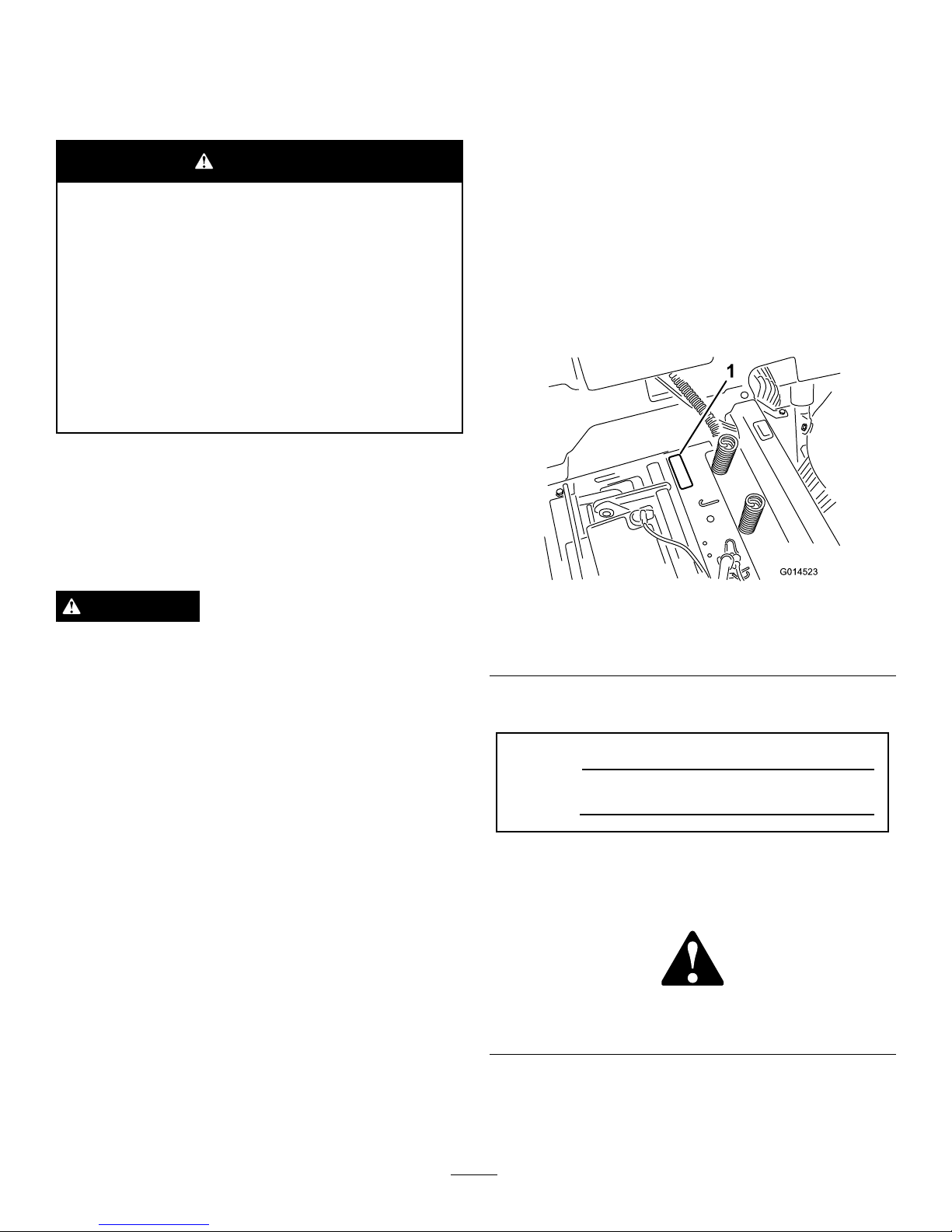
yourproductready .Figure1identiesthelocationofthe
modelandserialnumbersontheproduct.Writethenumbers
inthespaceprovided.
G014523
1
Figure1
Undertheseat
1.Modelandserialnumberplate
Writetheproductmodelandserialnumbersinthespace
below:
ModelNo.
SerialNo.
Thismanualidentiespotentialhazardsandhassafety
messagesidentiedbythesafetyalertsymbol(Figure2),
whichsignalsahazardthatmaycauseseriousinjuryordeath
ifyoudonotfollowtherecommendedprecautions.
Figure2
1.Safetyalertsymbol.
Thismanualusestwowordstohighlightinformation.
Importantcallsattentiontospecialmechanicalinformation
andNoteemphasizesgeneralinformationworthyofspecial
attention.
©2013—TheToro®Company
8111LyndaleAvenueSouth
Bloomington,MN55420
2
Contactusatwww.T oro.com.
PrintedintheUSA
AllRightsReserved
Page 3

Contents
Introduction..................................................................2
Safety...........................................................................4
SafeOperatingPractices...........................................4
ToroRidingMowerSafety........................................6
SlopeIndicator.......................................................7
SafetyandInstructionalDecals.................................8
ProductOverview.........................................................13
Controls...............................................................13
Operation....................................................................15
ThinkSafetyFirst...................................................15
BeforeStarting.......................................................16
StartingtheEngine.................................................17
OperatingtheBlades...............................................18
TestingtheSafetyInterlockSystem...........................19
StoppingtheEngine...............................................19
Driving.................................................................19
StoppingtheMachine.............................................20
AdjustingtheHeightofCut.....................................21
AdjustingtheAnti-ScalpRollers...............................21
PositioningtheSeat................................................21
AdjustingtheMotionControlLevers........................21
PushingtheMachinebyHand..................................22
GrassDeector......................................................23
OperatingTips......................................................23
Maintenance.................................................................24
RecommendedMaintenanceSchedule(s)......................24
PremaintenanceProcedures........................................25
RaisingtheSeat......................................................25
Lubrication...............................................................25
GreasingtheBearings.............................................25
EngineMaintenance..................................................26
ServicingtheAirCleaner.........................................26
ServicingtheEngineOil..........................................26
ServicingtheSparkPlug..........................................28
CleaningtheCoolingSystem....................................29
FuelSystemMaintenance...........................................30
ReplacingtheIn-lineFuelFilter................................30
ElectricalSystemMaintenance....................................31
ChargingtheBattery...............................................31
ServicingtheFuses.................................................32
DriveSystemMaintenance.........................................33
CheckingtheTirePressure......................................33
ReleasingtheElectricBrake.....................................33
HydraulicSystemMaintenance....................................34
CheckingtheHydraulicOilLevel..............................34
ChangingtheHydraulicSystemOiland
Filters................................................................34
MowerMaintenance...................................................36
ServicingtheCuttingBlades.....................................36
LevelingtheMowerDeck........................................39
RemovingtheMower..............................................40
MowerBeltMaintenance.........................................41
InstallingtheMower...............................................41
ReplacingtheGrassDeector..................................42
Cleaning...................................................................43
WashingtheUndersideoftheMower........................43
Storage........................................................................44
CleaningandStorage..............................................44
Troubleshooting...........................................................46
Schematics...................................................................48
3
Page 4

Safety
Toreducethepotentialforinjury,complywiththese
safetyinstructionsandalwayspayattentiontothesafety
alertsymbol,whichmeansCAUTION,WARNING,
orDANGER-"personalsafetyinstruction."Failure
tocomplywiththeinstructionmayresultinpersonal
injuryordeath.
SafeOperatingPractices
Thisproductiscapableofamputatinghandsandfeetand
throwingobjects.Alwaysfollowallsafetyinstructionsto
avoidseriousinjuryordeath.
ThefollowinginstructionsareadaptedfromANSIstandard
B71.1-2012.AllthelanguagewithinthisANSIstandard
appliestothismachine;however,duetotheapplicationof
thestandardacrossmanydifferenttypesofproductssome
statementscanseemgeneralormisleading.Intheseinstances,
Torohasrenedthestatementtoconveythemeaningofthe
standardwhilebettermatchingtheproductthisOperator's
Manualpertains.Safetyinformationinadditiontothe
instructionsfoundintheANSIstandardbelowcanbefound
inToroRidingMowerSafetyattheendofthissection.
GeneralOperation
•Read,understand,andfollowallinstructionsinthe
operator'smanualandonthemachinebeforestarting.
•Donotplacehandsorfeetnearrotatingpartsorunder
themachine.Keepclearofthedischargeopeningatall
times.
•Allowonlyresponsibleadultswhoarefamiliarwiththe
instructionstooperatethemachine.
•Cleartheareaofobjectssuchasrocks,toys,wire,etc.,
whichcouldbepickedupandthrownbytheblade.
•Besuretheareaisclearofotherpeoplebeforemowing.
Stopthemachineifanyoneentersthearea.
•Nevercarrypassengers.
•Donotmowinreverseunlessabsolutelynecessary.
Alwayslookdownandbehindbeforeandwhilebacking
up.
•Beawareofthemowerdischargedirectionanddonot
pointitatanyone.Avoiddischargingmaterialagainsta
wallorobstruction.Materialmayricochetbacktoward
theoperator.Stoptheblade(s)whencrossinggravel
surfaces.
•Donotoperatethemachinewithoutdeector,discharge
coverorentiregrasscollectionsysteminplaceand
working.
•Bealert,slowdownandusecautionwhenmakingturns.
Lookbehindandtothesidebeforechangingdirections.
•Neverleavearunningmachineunattended.Alwaysturn
offblades,setparkingbrake,stopengine,andremovekey
beforedismounting.
•Turnoffbladeswhennotmowing.Stoptheengine,wait
forallpartstocometoacompletestopandremovethe
keybeforecleaningthemachine,removingthegrass
catcheroruncloggingthedischargechute.
•Operatethemachineonlyindaylightorgoodarticial
light.
•Donotoperatethemachinewhileundertheinuence
ofalcoholordrugs.
•Watchfortrafcwhenoperatingnearorcrossing
roadways.
•Useextracarewhenloadingorunloadingthemachine
intoatrailerortruck.
•Alwaysweareyeprotectionwhenoperatingthemower.
•Dataindicatesthatoperators,age60yearsandabove,are
involvedinalargepercentageofridingmower-related
injuries.Operatorsshouldevaluatetheirabilitytooperate
theridingmowersafelyenoughtoprotectthemselvesand
othersfromseriousinjury.
•Alwaysfollowtherecommendationsforanyapplication
ofcounterweights.
•Lightningcancausesevereinjuryordeath.Iflightning
isseenorthunderisheardinthearea,donotoperate
themachine;seekshelter.
SlopeOperation
Slopesareamajorfactorrelatedtolossofcontroland
tip-overaccidents,whichcanresultinsevereinjuryordeath.
Operationonallslopesrequiresextracaution.Ifyoucannot
backuptheslopeorifyoufeeluneasyonit,donotmowit.
•Donotmowslopesgreaterthan15degrees.
•Watchforditches,holes,rocks,dips,andrisesthatchange
theoperatingangle,asroughterraincouldoverturnthe
machine.
•Choosealowgroundspeedsoyouwillnothavetostop
whileoperatingonaslope.
•Donotmowslopeswhengrassiswet.Slippery
conditionsreducetractionandcouldcauseslidingand
lossofcontrol.
•Alwayskeepthedrivewheelsengagedwhengoingdown
slopes.
•Reducespeedanduseextremecautiononslopes.
•Donotmakesuddenturnsorrapidspeedchanges.
•Removeormarkobstaclessuchasrocks,treelimbs,etc.
fromthemowingarea.Tallgrasscanhideobstacles.
•Avoidsuddenstartswhenmowinguphillbecausethe
mowermaytipbackwards.
•Beawarethatlossoftractionmayoccurgoingdownhill.
Weighttransfertothefrontwheelsmaycausedrive
wheelstoslipandcauselossofbrakingandsteering.
4
Page 5

•Alwaysavoidsuddenstartingorstoppingonaslope.If
tireslosetraction,stopthemachine,disengagetheblades
andproceedslowlyofftheslope.
•Useextremecarewithgrasscatchersorotherattachments.
Thesecanchangethestabilityofthemachineandcause
lossofcontrol.
•Donottrytostabilizethemachinebyputtingyourfoot
ontheground.
•Donotmowneardrop-offs,ditches,steepbanksor
water.Wheelsdroppingoveredgescancauserollovers,
whichmayresultinseriousinjury,deathordrowning.
•Useawalkbehindmowerand/orahandtrimmernear
drop-offs,ditches,steepbanksorwater.
Children
Tragicaccidentscanoccuriftheoperatorisnotalerttothe
presenceofchildren.Childrenareoftenattractedtothe
machineandthemowingactivity.Neverassumethatchildren
willremainwhereyoulastsawthem.
•Keepchildrenoutofthemowingareaandunderthe
watchfulcareofanotherresponsibleadult,notthe
operator.
•Bealertandturnthemachineoffifchildrenenterthe
area.
•Beforeandwhilebackingorchangingdirection,look
behind,down,andside-to-sideforsmallchildren.
•Nevercarrychildren,evenwiththebladesoff.Theymay
falloffandbeseriouslyinjuredorinterferewithsafe
machineoperation.
•Childrenwhohavebeengivenridesinthepastmay
suddenlyappearinthemowingareaforanotherrideand
berunoverorbackedoverbythemower.
•Neverallowchildrentooperatethemachine.
•Useextracarewhenapproachingblindcorners,shrubs,
trees,theendofafenceorotherobjectsthatmayobscure
vision.
TowingSafety
•Donotattachtowedequipmentexceptatthehitchpoint.
•Followtheattachmentmanufacturer'srecommendation
forweightlimitsfortowedequipmentandtowingon
slopes.Towedweightmustnotexceedtheweightofthe
machine,operator,andballast.Usecounterweightsor
wheelweightsasdescribedintheattachment,orinthe
pullingmachineOperator’sManual.
•Neverallowchildrenorothersinorontowedequipment.
•Onslopes,theweightofthetowedequipmentmaycause
lossoftraction,increasedriskofrollover,andlossof
control.Reducethetowedweightandslowdown.
•Stoppingdistanceincreaseswiththeweightofthetowed
load.Travelslowlyandallowextradistancetostop.
•Makewideturnstokeeptheattachmentclearofthe
machine.
Service
SafeHandlingofGasoline:
Toavoidpersonalinjuryorpropertydamage,useextracare
whenhandlinggasolineandotherfuels.Theyareammable
andthevaporsareexplosive.
•Extinguishallcigarettes,cigars,pipesandothersources
ofignition.
•Useonlyanapprovedcontainer.
•Neverremovethegascaporaddfuelwhentheengineis
running.Allowtheenginetocoolbeforerefueling.
•Neverrefuelthemachineindoors.
•Neverstorethemachineorfuelcontainerinsidewhere
thereisanopename,suchasnearawaterheateror
furnace.
•Neverllcontainersinsideavehicleoronatruckor
trailerwithaplasticliner.Alwaysplacecontainersonthe
groundawayfromyourvehiclebeforelling.
•Removegas-poweredequipmentfromthetruckortrailer
andrefuelitontheground.Ifthisisnotpossible,then
refuelsuchequipmentwithaportablecontainer,rather
thanfromagasolinedispensernozzle.
•Keepthenozzleincontactwiththerimofthefueltank
orcontaineropeningatalltimesuntilthefuelingis
complete.Donotuseanozzlelock-opendevice.
•Iffuelisspilledonclothing,changeclothingimmediately.
•Neveroverllthefueltank.Replacegascapandtighten
securely.
GeneralService:
•Neveroperateamachineinsideaclosedarea.Engine
exhaustcontainscarbonmonoxide,whichisanodorless,
deadlypoisonthatcankillyou.
•Keepnutsandboltstight,especiallythebladeattachment
bolts.Keepequipmentingoodcondition.
•Neverinterferewiththeintendedfunctionofasafety
deviceortoreducetheprotectionprovidedbyasafety
device.Checktheirproperoperationregularly.
•Keepthemachinefreeofgrass,leaves,orotherdebris
build-up.Cleanupoilorfuelspillagefuelsoakeddebris.
Allowthemachinetocoolbeforestoring.
•Stopandinspecttheequipmentifyoustrikeanobject.
Repair,ifnecessary,beforerestarting.
•Nevermakeanyadjustmentsorrepairswiththeengine
running.
•Grasscatchercomponentsaresubjecttowear,damage
anddeterioration,whichcouldexposemovingpartsor
allowobjectstobethrown.Frequentlycheckcomponents
andreplacewithmanufacturers'recommendedparts,
whennecessary.
•Mowerbladesaresharpandcancut.Wraptheblade(s)or
weargloves,anduseextracautionwhenservicingthem.
•Checkforproperbrakeoperationfrequently.Adjustand
serviceasrequired.
5
Page 6

•Maintainorreplacesafetyandinstructiondecalsas
necessary.
•UseonlygenuineTororeplacementpartstoensurethat
originalstandardsaremaintained.
ToroRidingMowerSafety
ThefollowinglistcontainssafetyinformationspecictoToro
productsorothersafetyinformationthatyoumustknowthat
maynotbeincludedintheANSIstandards.
•Stoptheengine,movethemotioncontrolleverstoneutral
andoutwardtotheparkposition,disengagetheblade
controlswitch,removekeybeforeanddisconnectspark
plugwire(s)performinganyservice,repairs,maintenance
oradjustments.
•Keephands,feet,hair,andlooseclothingawayfrom
attachmentdischargearea,undersideofmowerandany
movingpartswhileengineisrunning.
•Donottouchequipmentorattachmentpartswhichmay
behotfromoperation.Allowtocoolbeforeattempting
tomaintain,adjustorservice.
•Batteryacidispoisonousandcancauseburns.Avoid
contactwithskin,eyes,andclothing.Protectyourface,
eyes,andclothingwhenworkingwithabattery.
•Batterygasescanexplode.Keepcigarettes,sparksand
amesawayfrombattery.
•UseonlyToroapprovedattachments.Warrantymaybe
voidedifusedwithunapprovedattachments.
•Ifloadingthemachineontoatrailerortruck,useasingle,
full-widthramponly.Therampangleshouldnotexceed
15degrees.
6
Page 7
SlopeIndicator
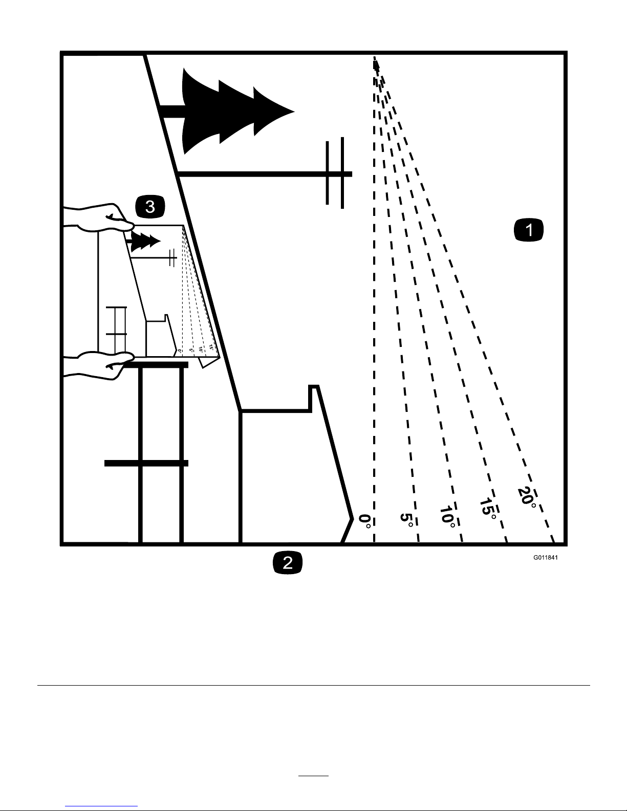
G011841
Figure3
Thispagemaybecopiedforpersonaluse.
1.Themaximumslopeyoucansafelyoperatethemachineonis15degrees.Usetheslopecharttodeterminethedegreeofslope
ofhillsbeforeoperating.Donotoperatethismachineonaslopegreaterthan15degrees.Foldalongtheappropriateline
tomatchtherecommendedslope.
2.Alignthisedgewithaverticalsurface,atree,building,fencepole,etc.
3.Exampleofhowtocompareslopewithfoldededge.
7
Page 8
SafetyandInstructional
Decals
Safetydecalsandinstructionsareeasilyvisibletotheoperatorandarelocatednearanyareaofpotential
danger.Replaceanydecalthatisdamagedorlost.
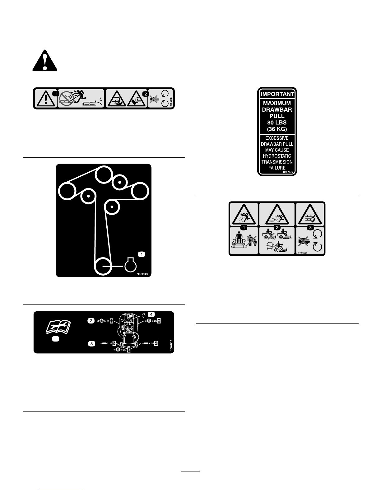
93-7009
1.Warning—don'toperatethemowerwiththedeectorupor
removed;keepthedeectorinplace.
2.Cutting/dismembermenthazardofhandorfoot,mower
blade—stayawayfrommovingparts.
99-3943
1.Engine
106-8717
1.Readtheinstructionsbeforeservicingorperforming
maintenance.
2.Checktirepressureevery25operatinghours.
3.Greaseevery25operatinghours.
4.Engine
109-7076
110-6691
1.Thrownobjecthazard—keepbystandersasafedistance
fromthemachine.
2.Thrownobjecthazard,mower—donotoperatewithoutthe
deector,dischargecover,orgrasscollectionsystemin
place.
3.Cutting/dismembermentofhandorfoot—stayawayfrom
movingparts.
8
Page 9
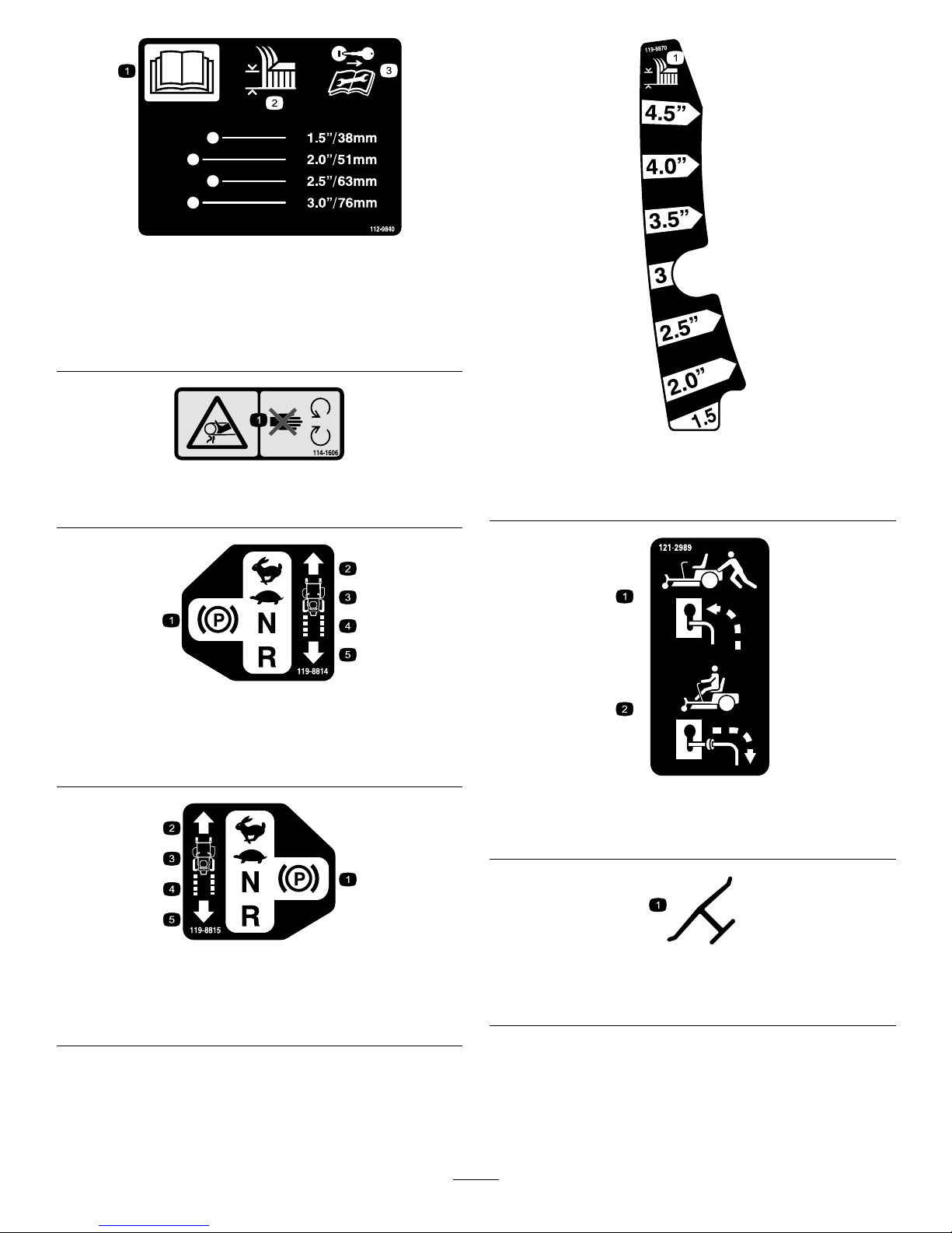
112-9840
1.ReadtheOperator's
Manual.
3.Removetheignitionkey
andreadtheinstructions
beforeservicingor
performingmaintenance.
2.Heightofcut
114-1606
1.Entanglementhazard,belt—keepallguardsinplace.
119-8814
1.Parkingposition4.Neutral
2.Fast5.Reverse
3.Slow
119-8815
1.Parkingposition4.Neutral
2.Fast5.Reverse
3.Slow
119-8870
50InchModel
1.Height-of-cut
121-2989
1.Bypassleverpositionfor
pushingthemachine
2.Bypassleverpositionfor
operatingthemachine
Manufacturer'sMark
1.Indicatesthebladeisidentiedasapartfromtheoriginal
machinemanufacturer.
9
Page 10

BatterySymbols
Someorallofthesesymbolsareonyourbattery
1.Explosionhazard
6.Keepbystandersasafe
distancefromthebattery .
2.Nore,opename,or
smoking.
7.Weareyeprotection;
explosivegasescan
causeblindnessandother
injuries
3.Causticliquid/chemical
burnhazard
8.Batteryacidcancause
blindnessorsevereburns.
4.Weareyeprotection9.Flusheyesimmediately
withwaterandgetmedical
helpfast.
5.ReadtheOperator's
Manual.
10.Containslead;donot
discard.
10
Page 11
130-0780
1.Lowspeed—trimmingand
towing
2.Highspeed—mowingand
transport
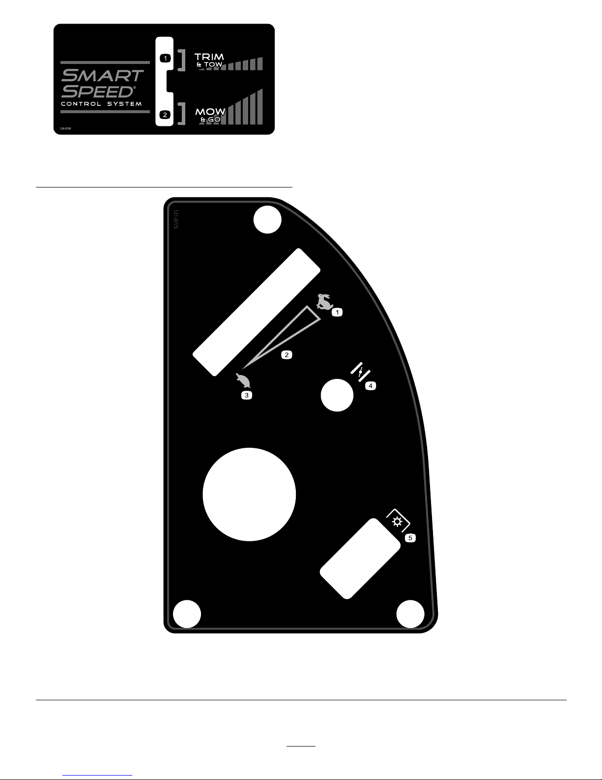
121-0773
1.Fast
4.Choke
2.Continuousvariablesetting5.Powertake-off(PTO),Bladecontrolswitch
3.Slow
11
Page 12
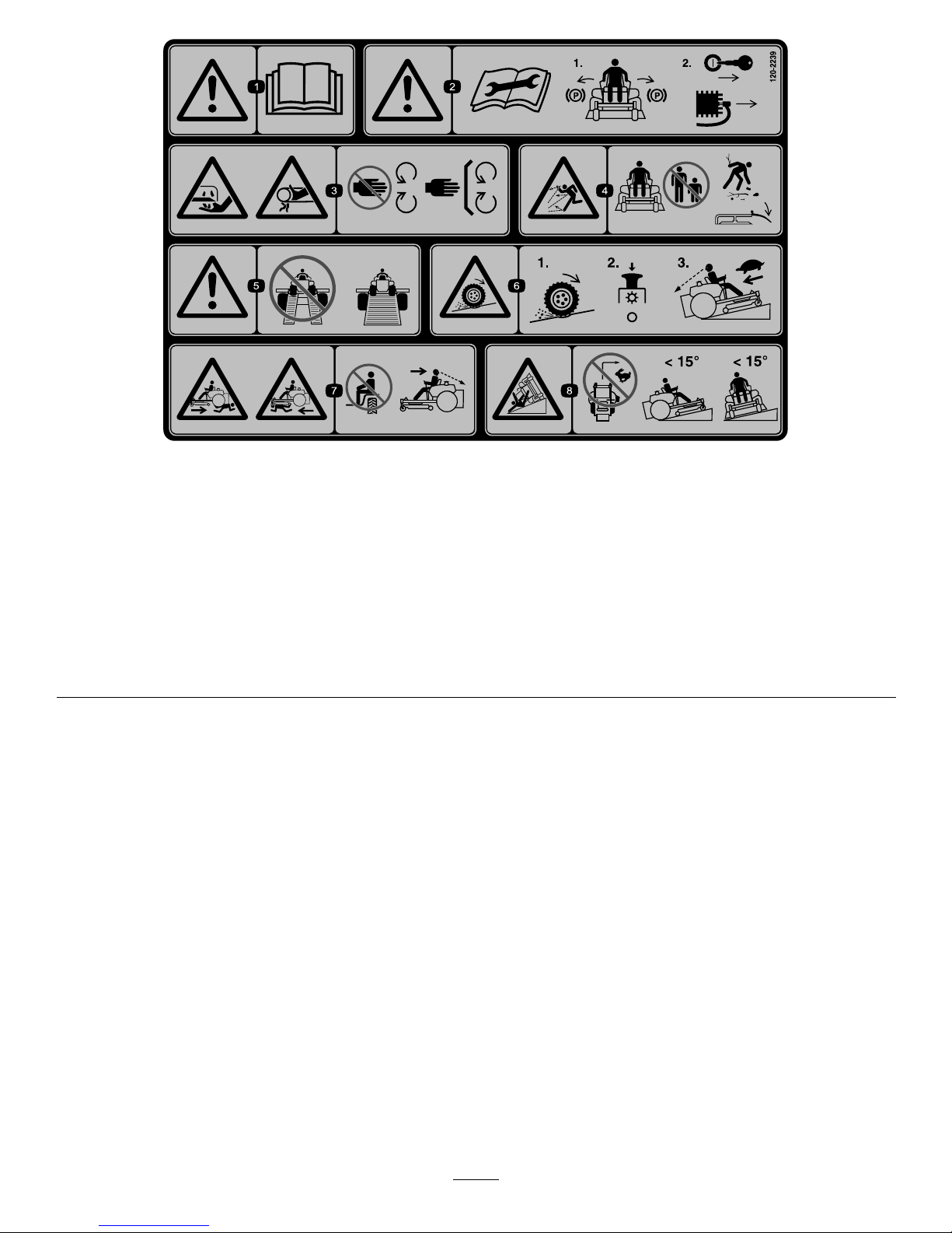
120-2239
1.Warning—readtheOperator'sManual.5.Warning—donotusesplitramps,useafullrampswhen
transportingmachine.
2.Warning—readtheinstructionsbeforeservicingorperforming
maintenance;movethemotioncontrolleverstothepark
(brake)position,removetheignitionkeyanddisconnectthe
sparkplugwire.
6.Lossoftraction/controlhazard,slopes—lossoftraction/control
onaslope,disengagethebladecontrolswitch(PTO),
proceedofftheslopeslowly .
3.Cutting/dismembermenthazard,mowerblade;entanglement
hazard,belt—stayawayfrommovingparts,keepallguards
andshieldsinplace.
7.Crushing/dismembermenthazardofbystanders,reversing;
crushing/dismembermenthazardofbystanders—donotcarry
passengers,lookbehindanddownwhenreversing.
4.Thrownobjecthazard—keepbystandersasafedistancefrom
themachine,pickupdebrisbeforeoperating,keepdeector
inplace.
8.Tippinghazard—donotmowslopesgreaterthan15degrees,
avoidsuddenandsharpturnswhileonslopes.
12
Page 13
ProductOverview
G020177
4
3
2
1
8 15
9
10
11
12
13
6
5
14
7
5
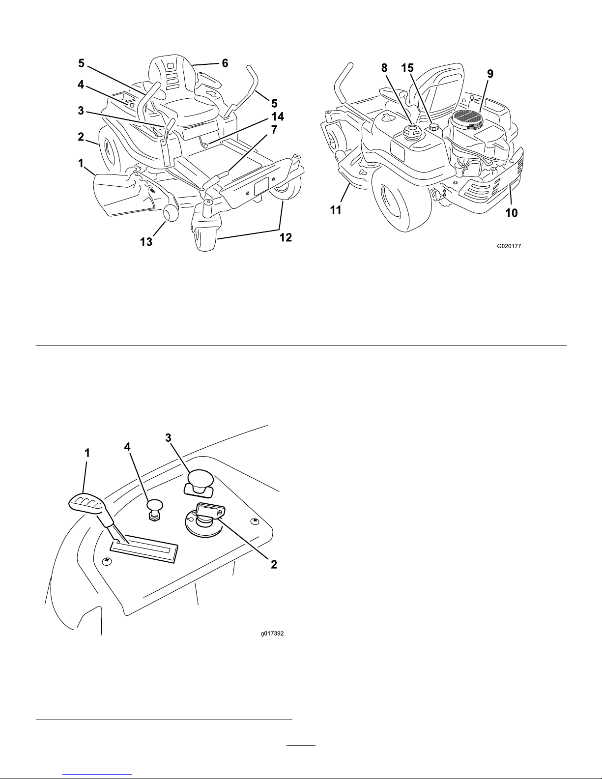
Figure4
1.Deector
5.Motioncontrollevers9.Engine13.Anti-scalproller
2.Reardrivewheel
6.Operatorseat
10.Engineguard
14.SmartSpeed™lever
3.Heightofcutlever7.Footassistlever(certain
modelsonly)
11.Mowerdeck15.Hydraulicreservoir
4.Controlpanel8.Gastankcap
12.Frontcasterwheel
Controls
BecomefamiliarwithallofthecontrolsinFigure4and
Figure5beforeyoustarttheengineandoperatethemachine.
Figure5
ControlPanel
1.Throttle3.Bladecontrolswitch
(powertake-off)
2.Ignitionswitch
4.Choke
IgnitionSwitch
Theignitionswitchhasthreepositions,Off,RunandStart.
ThekeywillturntoStartandmovebacktoRunuponrelease.
TurningthekeytotheOffpositionwillstoptheengine;
however,alwaysremovethekeywhenleavingthemachine
topreventsomeonefromaccidentallystartingtheengine
(Figure5).
ThrottleControl
Thethrottlecontrolstheenginespeedandithasacontinuous
variablesettingfromSlowtoFast(Figure5).
ChokeControl
PullupontheChokecontroluntilitstopstochokethe
engine(Figure5).PushdownontheChokecontrolfor
normalengineoperation
BladeControlSwitch(PowerTake-Off)
Thebladecontrolswitch,representedbyapowertake-off
(PTO)symbol,engagesanddisengagespowertothemower
blades(
Figure5).
13
Page 14
MotionControlLeversandParking
BrakePosition
Themotioncontrolleversarespeedsensitivecontrolsof
independentwheelmotors.Movingaleverforwardor
backwardturnsthewheelonthesamesideforwardorin
reverse;wheelspeedisproportionaltotheamountthelever
ismoved.Movethecontrolleversoutwardfromthecenter
totheparkpositionandexitthemachine(Figure17).Always
positionthemotioncontrolleversintotheparkposition
whenyoustopthemachineorleaveitunattended.
SmartSpeed™ControlSystemLever
TheSmartSpeed™ControlSystemlever,locatedbelowthe
operatingposition,givestheoperatorachoicetodrivethe
machineattwospeedranges,highandlow(Figure6).
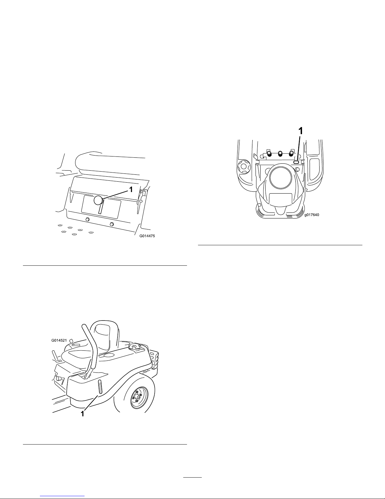
G014475
1
Figure6
1.Smartspeedlever
FuelWindow
Thefuelwindowlocatedonthelefthandsideofthemachine
canbeusedtoverifythepresenceofgasolineinthetank
(Figure7).
G014521
1
Figure7
1.Fuelpresencewindow
Height-of-CutLever
Theheightofcutleverallowstheoperatortolowerand
raisethedeckfromtheseatedposition.Whentheleveris
movedup,towardtheoperatorthedeckisraisedfromthe
groundandwhenmoveddown,awayfromtheoperatoritis
loweredtowardtheground.Onlyadjusttheheightofcut
whilemachineisnotmoving(Figure4).
HourMeter
Thehourmeterrecordsthenumberofhourswhenthe
operatorisintheseatandtheignitionswitchisintheON
position(Figure8).
g017640
1
Figure8
1.Hourmeterlocationbehindtheseat
14
Page 15
Operation
Note:Determinetheleftandrightsidesofthemachine
fromthenormaloperatingposition.
ThinkSafetyFirst
OperatingSafety
Pleasecarefullyreadallofthesafetyinstructionsanddecals
inthesafetysection.Knowingthisinformationcouldhelp
you,yourfamily,petsorbystandersavoidinjury.
DANGER
Mowingonwetgrassorsteepslopescancause
slidingandlossofcontrol.
Wheelsdroppingoveredgescancauserollovers,
whichmayresultinseriousinjury,deathor
drowning.
Alossoftractionisalossofsteeringcontrol.
Toavoidlossofcontrolandpossibilityofrollover:
•Donotmowneardrop-offsornearwater.
•Donotmowslopesgreaterthan15degrees.
•Reducespeedanduseextremecautionon
slopes.
•Whenmowingslopes,graduallyworkfrom
lowertohigherareasontheincline.
•Avoidsuddenturnsorrapidspeedchanges.
•Turnup,intoaninclinewhenchanging
directionsonslopes.Turningdowntheslope
reducestraction.
•Attachmentschangethehandlingcharacteristics
ofthemachine.Useextracautionwhenusing
attachmentswiththemachine.
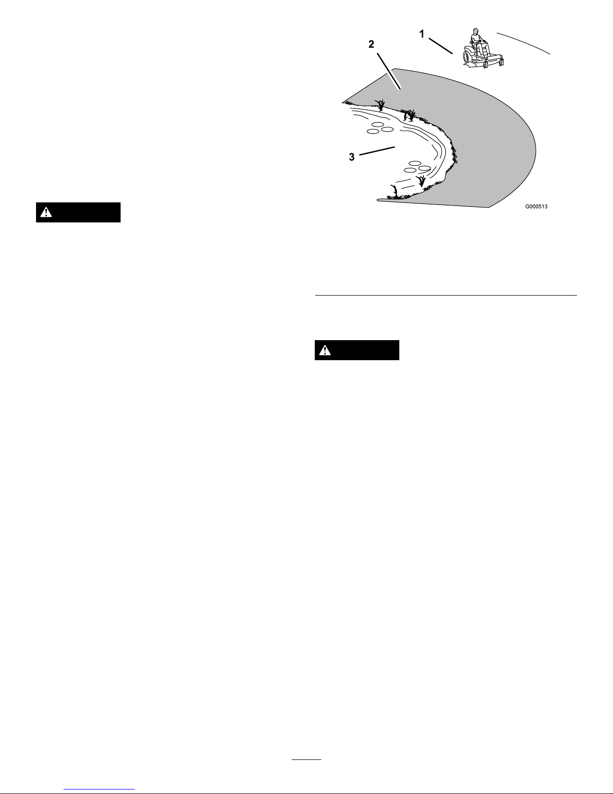
Figure9
1.SafeZone-usethe
TimeCutterhere
3.Water
2.Usewalkbehindmower
and/orhandtrimmernear
drop-offsandwater .
FuelSafety
DANGER
Incertainconditions,gasolineisextremely
ammableandhighlyexplosive.Areorexplosion
fromgasolinecanburnyouandothersandcan
damageproperty.
•Fillthefueltankoutdoors,inanopenarea,
whentheengineiscold.Wipeupanygasoline
thatspills.
•Neverllthefueltankinsideanenclosedtrailer.
•Donotllthefueltankcompletelyfull.Add
gasolinetothefueltankuntilthefuelreaches
thebaseofthellerneck.Thisemptyspacein
thetankallowsgasolinetoexpand.
•Neversmokewhenhandlinggasoline,andstay
awayfromanopenameorwheregasoline
fumesmaybeignitedbyaspark.
•Storegasolineinanapprovedcontainerand
keepitoutofthereachofchildren.Neverbuy
morethana30-daysupplyofgasoline.
•Donotoperatewithoutentireexhaustsystemin
placeandinproperworkingcondition.
15
Page 16

DANGER
Incertainconditionsduringfueling,static
electricitycanbereleasedcausingasparkwhich
canignitethegasolinevapors.Areorexplosion
fromgasolinecanburnyouandothersandcan
damageproperty.
•Alwaysplacegasolinecontainersontheground
awayfromyourvehiclebeforelling.
•Donotllgasolinecontainersinsideavehicleor
onatruckortrailerbedbecauseinteriorcarpets
orplastictruckbedlinersmayinsulatethe
containerandslowthelossofanystaticcharge.
•Whenpractical,removegas-poweredequipment
fromthetruckortrailerandrefueltheequipment
withitswheelsontheground.
•Ifthisisnotpossible,thenrefuelsuch
equipmentonatruckortrailerfromaportable
container,ratherthanfromagasolinedispenser
nozzle.
•Ifagasolinedispensernozzlemustbeused,
keepthenozzleincontactwiththerimofthe
fueltankorcontaineropeningatalltimesuntil
fuelingiscomplete.
WARNING
Gasolineisharmfulorfatalifswallowed.Long-term
exposuretovaporscancauseseriousinjuryand
illness.
•Avoidprolongedbreathingofvapors.
•Keepfaceawayfromnozzleandgastankor
conditioneropening .
•Keepgasawayfromeyesandskin.
UnderstandingtheSafetyInterlock
System
WARNING
Ifsafetyinterlockswitchesaredisconnectedor
damagedthemachinecouldoperateunexpectedly
causingpersonalinjury.
•Donottamperwiththeinterlockswitches.
•Checktheoperationoftheinterlockswitches
dailyandreplaceanydamagedswitchesbefore
operatingthemachine.
Thesafetyinterlocksystemisdesignedtopreventtheengine
fromstartingunless:
•Thebladesaredisengaged.
•Themotioncontrolleversareintheparkposition.
Thesafetyinterlocksystemalsoisdesignedtostoptheengine
wheneverthecontrolleversareoutoftheparkpositionand
yourisefromtheseat.
BeforeStarting
RecommendedFuel
•Forbestresults,useonlyclean,fresh(lessthan30days
old),unleadedgasolinewithanoctaneratingof87or
higher((R+M)/2ratingmethod).
•Ethanol:Gasolinewithupto10%ethanol(gasohol)
or15%MTBE(methyltertiarybutylether)byvolume
isacceptable.EthanolandMTBEarenotthesame.
Gasolinewith15%ethanol(E15)byvolumeisnot
approvedforuse.Neverusegasolinethatcontains
morethan10%ethanolbyvolume,suchasE15
(contains15%ethanol),E20(contains20%ethanol),or
E85(containsupto85%ethanol).Usingunapproved
gasolinemaycauseperformanceproblemsand/orengine
damagewhichmaynotbecoveredunderwarranty.
•Donotusegasolinecontainingmethanol.
•Donotstorefueleitherinthefueltankorfuelcontainers
overthewinterunlessafuelstabilizerisused.
•Donotaddoiltogasoline.
UsingStabilizer/Conditioner
Useafuelstabilizer/conditionerinthemachinetoprovide
thefollowingbenets:
•Keepsgasolinefreshduringstorageof90daysorless.
Forlongerstorageitisrecommendedthatthefueltank
bedrained.
•Cleanstheenginewhileitruns.
•Eliminatesgum-likevarnishbuildupinthefuelsystem,
whichcauseshardstarting.
Addthecorrectamountofgasstabilizer/conditionertothe
gas.
Note:Afuelstabilizer/conditionerismosteffectivewhen
mixedwithfreshgasoline.T ominimizethechanceofvarnish
depositsinthefuelsystem,usefuelstabilizeratalltimes.
CheckingtheEngineOilLevel
Beforeyoustarttheengineandusethemachine,checktheoil
levelintheenginecrankcase;refertoCheckingtheOilLevel
intheEngineMaintenancesection.
FillingtheFuelTank
Makesuretheengineisshutoffandthemotioncontrolsare
intheparkposition.Tankmaximumcapacityis2.9gallons.
Important:DoNotoverllfueltank.Fillthefueltank
tothebottomofthellerneck.Theemptyspaceinthe
16
Page 17

tankallowsthefueltoexpand.Overllingmayresultin
fuelleakageordamagetotheengineoremissionsystem.
1.Cleanaroundthefueltankcapandremovethecap.
Note:Youcanusethefuelwindowtoverifythe
presenceofgasolinebeforellingthetank(
Figure10).
2.Slowlyaddregular,unleadedgasolineuntilthefuel
reachesthebaseofthellerneck(Figure10).
G014474
1
2
3
4
5
6
Figure10
1.Fueltankcap
4.Baseofllerneck,DO
NOTFILLP ASTHERE
2.Fillopening5.Fuelwindow
3.Fillerneck6.Fueltank
G014895
1
2
3
4
Figure11
1.Fillopening3.Fuel
2.Baseofllerneck,DO
NOTFILLP ASTHERE
4.Emptyspaceforfuel
expansion.
3.Installthefueltankcapsecurelyandtightenuntilit
“clicks”.Wipeupanygasolinethatmayhavespilled.
StartingtheEngine
1.Sitdownontheseatandmovethemotioncontrols
outwardtotheparkposition.
2.Movethethrottletothefastposition(Figure12).
3.Disengagethebladesbymovingthebladecontrol
switchtoOff(Figure12).
Figure12
1.Throttle
2.Bladecontrolswitch—Off
position
4.PullupontheChokecontrolbeforestartingacold
engine(Figure13).
Note:Awarmorhotenginemaynotrequirechoking.
g017699
4
5
Figure13
1.Controlpanel4.Slow
2.Throttle
5.Chokecontrol
3.Fast
5.TurntheignitionkeytoStarttoenergizethestarter.
Whentheenginestarts,releasethekey(Figure14).
Important:Donotengagethestarterformore
than10secondsatatime.Iftheenginefailsto
start,allowa60secondcool-downperiodbetween
17
Page 18

attempts.Failuretofollowtheseinstructionscan
damagethestartermotor.
g017700
2
3
4
5
6
Figure14
1.Controlpanel4.Off
2.Chokecontrol
5.Run
3.Ignitionkey
6.Start
6.Aftertheenginestarts,pushdownontheChoke
control(Figure14).Iftheenginestallsorhesitates,pull
upontheChokecontrolandlettheenginerunfora
fewseconds.ThenpushdownontheChokecontrol.
Repeatthisasrequired.
OperatingtheBlades
Thebladecontrolswitch,representedbyapowertake-off
(PTO)symbol,engagesanddisengagespowertothemower
blades.Thisswitchcontrolspowertoanyattachmentsthat
drawpowerfromtheengine,includingthemowerdeckand
cuttingblades.
EngagingtheBlades
Important:Donotengagethebladeswhenparkedin
tallgrass.Beltorclutchdamagecanoccur.
1.Releasepressureonthemotioncontrolleversand
placethemachineinneutral.
2.MovethethrottletotheFastposition.
Note:Alwaysengagethebladeswiththethrottlein
theFastposition.
3.Pulluponthebladecontrolswitchtomoveittothe
Onpositionandengagetheblades(
Figure15).
Figure15
1.Controlpanel2.Bladecontrolswitch—On
position
DisengagingtheBlades
PushdownonthebladecontrolswitchtomoveittotheOff
positionanddisengagetheblades(Figure16).
Figure16
1.Controlpanel2.Bladecontrolswitch—Off
18
Page 19

TestingtheSafetyInterlock
System
Testthesafetyinterlocksystembeforeyouusethemachine
eachtime.Ifthesafetysystemdoesnotoperateasdescribed
below,haveanAuthorizedServiceDealerrepairthesafety
systemimmediately.
1.Whilesittingontheseat,withthecontrolleversinpark
position,andmovethebladecontrolswitchtoOn.Try
startingtheengine;theengineshouldnotcrank.
2.Whilesittingontheseat,movethebladecontrol
switchtoOff.Moveeithermotioncontrollevertothe
center,unlockedposition.Trystartingtheengine;the
engineshouldnotcrank.Repeatwiththeothermotion
controllever.
3.Whilesittingontheseat,movethebladecontrolswitch
toOff,andlockthemotioncontrolleversinthepark
position.Starttheengine.Whiletheengineisrunning,
engagethebladecontrolswitch,andriseslightlyfrom
theseat;theengineshouldstop.
4.Whilesittingontheseat,movethebladecontrolswitch
toOff,andlockthemotioncontrolleversinthepark
position.Starttheengine.Whiletheengineisrunning,
movethemotioncontrolleverstothecenter,unlocked
position,engagethebladecontrolswitch,andrise
slightlyfromtheseat;theengineshouldstop.
StoppingtheEngine
1.Disengagethebladesbymovingthebladecontrol
switchtoOff(Figure16).
2.MovethethrottlelevertobetweentheFastposition
(Figure13).
3.TurntheignitionkeytoOff(Figure14)andremove
thekey.
Driving
Drivingthemachinebenetsfromanunderstandingof
whatzeroturnradiusmowermeans.Thedrivewheelsturn
independently,poweredbyhydraulicmotorsoneachaxle;
henceonesidecanturninreversewhiletheotherturns
forwardcausingthemachinetospinratherthanturn.This
vastlyimprovesthemachinemaneuverabilitybutmayrequire
someadjustmentiftheoperatorisunfamiliar.
WARNING
Themachinecanspinveryrapidly .Theoperator
maylosecontrolofthemachineandcausepersonal
injuryordamagetothemachine.
•Usecautionwhenmakingturns.
•Slowthemachinedownbeforemakingsharp
turns.
Thethrottlecontrolregulatestheenginespeedasmeasured
inrpm(revolutionsperminute).Placingthethrottlecontrol
intheFastpositioncanbebestforperformance.Formost
applications,operatinginthefullthrottlepositionisdesirable.
Figure17
1.Park(brake)position
4.Backward
2.Centerunlockposition5.Frontofmachine
3.Forward
UsingtheSmartSpeed™Control
System
TheSmartSpeed™ControlSystemlever,locatedbelowthe
operatingposition(
Figure18),givestheoperatorachoiceto
drivethemachineattwogroundspeedranges,highandlow .
G014475
1
Figure18
1.Smartspeedlever
19
Page 20

Tochangespeeds:
1.Movethemotioncontrolleverstoneutralandoutward
totheparkposition;disengagethebladecontrolswitch.
WARNING
Removingyourhandsfromthemotioncontrol
leverswhilethemachineisinmotioncan
resultinalossofcontrolcausingharmtoyou
orbystanders.
Alwaysstopthemachineandmovethemotion
controlleverstotheparkpositionbefore
adjustingtheSmartSpeed™ControlSystem.
2.Adjustthelevertothedesiredposition.
Forward
1.Movetheleverstothecenter,unlockedposition.
2.Togoforward,slowlypushthemotioncontrollevers
forward(
Figure17).
G008952
Figure19
Togostraight,applyequalpressuretobothmotion
controllevers(
Figure19).
Toturn,releasepressureonthemotioncontrollever
towardthedirectionyouwanttoturn(Figure19).
Thefartheryoumovethemotioncontrolleversin
eitherdirection,thefasterthemachinewillmovein
thatdirection.
Tostop,pullthemotioncontrolleverstoneutral.
Backward
1.Movetheleverstothecenter,unlockedposition.
2.Togobackward,lookbehindyouanddownasyou
slowlypullthemotioncontrolleversrearward(Figure
20).
G008953
Figure20
Togostraight,applyequalpressuretobothmotion
controllevers(Figure20).
Toturn,releasethepressureonthemotioncontrol
levertowardthedirectionyouwanttoturn.
Tostop,pushthemotioncontrolleverstoneutral.
StoppingtheMachine
Tostopthemachine,movethemotioncontrolleversto
neutralandoutwardtotheparkposition,disengagetheblade
controlswitch,ensurethethrottleisinthefastposition,and
turntheignitionkeytoOff.Remembertoremovethekey
fromtheignitionswitch.
WARNING
Childrenorbystandersmaybeinjuredifthey
moveorattempttooperatethemowerwhileitis
unattended.
Alwaysremovetheignitionkeyandmovethe
motioncontrolleversoutwardtotheparkposition
whenleavingthemachineunattended,evenifjust
forafewminutes.
20
Page 21

AdjustingtheHeightofCut
Height-of-cutiscontrolledbytheleverlocatedtotherightof
theoperatingposition(Figure21).
G014476
1
2
3
Figure21
1.Height-of-cutlever3.4.5inch(115mm),
Transportposition
2.Height-of-cutpositions
1.Pullupandinwardonthelevertomoveittothe
desiredcuttingposition.
2.Onceatthedesiredcuttingposition,slowlylowerthe
leveruntilitengagestheposition.
Thetransportpositionisthehighestheight-of-cutpositionor
cuttingheight4.5inch[115mm](Figure21).
AdjustingtheAnti-Scalp
Rollers
Wheneveryouchangetheheight-of-cut,adjusttheheight
oftheanti-scalprollers.
Note:Adjusttheanti-scalprollerssotherollersdonottouch
thegroundinnormal,atmowingareas.
1.Disengagethebladecontrolswitch(PTO),movethe
motioncontrolleverstotheneutrallockpositionand
settheparkingbrake.
2.Stoptheengine,removethekey ,andwaitforallmoving
partstostopbeforeleavingtheoperatingposition.
3.Adjusttheanti-scalprollersasshownin
Figure22to
matchtheclosestheight-of-cutposition.
G010233
1
2
3
4
Figure22
1.Anti-scalproller3.FlangeNut
2.Bolt4.Holespacing
PositioningtheSeat
Whilesittingintheoperator’sposition,raisetheseat
adjustmentleverslightlyandmovetheseatforwardor
backwardtothedesiredposition(Figure23).
1
G014969
Figure23
AdjustingtheMotionControl
Levers
AdjustingtheHeight
Themotioncontrolleverscanbeadjustedhigherorlowerfor
maximumoperatorcomfort.
1.Removethe2boltsholdingthecontrollevertothe
controlarmshaft(
Figure24).
2.Movethecontrollevertothenextsetofholes.Secure
theleverwiththe2bolts(Figure24).
21
Page 22

4
1
2
G014970
3
Figure24
1.Controlarmshaft3.Slotted,upperhole
2.Controllever
4.Bolt
3.Repeattheadjustmentfortheoppositecontrollever.
AdjustingtheTilt
Themotioncontrolleverscanbetiltedforeoraftfor
maximumoperatorcomfort.
1.Loosentheupperboltholdingthecontrollevertothe
controlarmshaft.
2.Loosenthelowerboltjustenoughtopivotthecontrol
leverforeoraft(Figure24).Tightenbothboltsto
securethecontrolinthenewposition.
3.Repeattheadjustmentfortheoppositecontrollever.
PushingtheMachinebyHand
Important:Alwayspushthemachinebyhand.Never
towthemachinebecausedamagemayoccur.
Thismachinehasanelectricbrakemechanismandtopush
themachinetheignitionkeyneedstobeintheRunposition.
Thebatteryneedstobechargedandfunctioningforthe
electricbraketobedisengage.
ToPushtheMachine
1.Parkthemachineonalevelsurfaceanddisengagethe
bladecontrolswitch.
2.Movethemotioncontrolleversoutwardtopark
position,stoptheengine,andwaitforallmovingparts
tostopbeforeleavingtheoperatingposition.
3.Locatethebypassleversontheframeonbothsidesof
theengine.
4.Movethebypassleversforwardthroughthekeyhole
anddowntolocktheminplaceasshownin
Figure25.
Ensurethisisdoneforeachlever.
5.Movethemotioncontrolleversinwardtotheneutral
positionandturntheignitionkeytotherunposition.
Donotstartthemachine.
Themachineisnowabletobepushedbyhand.
g017303
1 2
3
Figure25
1.Bypassleverlocation
3.Leverpositionforpushing
themachine
2.Leverpositionfor
operatingthemachine
6.Whennished,ensurethekeyhasbeenreturnedtothe
Stoppositiontoavoiddrainingthebatterycharge.
Ifthemachinefailstomovetheelectricbrakemaystillbe
engaged.Ifnecessarytheelectricbrakecanbereleased
manually.RefertotheReleasingtheElectricBrake(page33)
procedureinDriveMaintenance.
ToOperatetheMachine
Movethebypassleversrearwardthroughthekeyholeand
downtolocktheminplaceasshowninFigure25.Ensure
thisisdoneforeachlever.
22
Page 23

GrassDeector
Themowerhasahingedgrassdeectorthatdisperses
clippingstothesideanddowntowardtheturf.
DANGER
Withoutthegrassdeector,dischargecover,or
completegrasscatcherassemblymountedin
place,youandothersareexposedtobladecontact
andthrowndebris.Contactwithrotatingmower
blade(s)andthrowndebriswillcauseinjuryor
death.
•Neverremovethegrassdeectorfromthemower
becausethegrassdeectorroutesmaterialdown
towardtheturf.Ifthegrassdeectorisever
damaged,replaceitimmediately .
•Neverputyourhandsorfeetunderthemower.
•Nevertrytocleardischargeareaormower
bladesunlessyoumovethebladecontrolswitch
toOffandrotatetheignitionkeytoOff.Also
removethekeyandpullthewireoffthespark
plug(s).
OperatingTips
FastThrottleSetting
Forbestmowingandmaximumaircirculation,operatethe
engineattheFastposition.Airisrequiredtothoroughlycut
grassclippings,sodonotsettheheight-of-cutsolowasto
totallysurroundthemowerbyuncutgrass.Alwaystrytohave
onesideofthemowerfreefromuncutgrass,whichallowsair
tobedrawnintothemower.
UsingtheSmartSpeed™Control
System
TheSmartSpeed™ControlSystemlever,locatedbelowthe
operatingposition,givestheoperatorachoicetodrivethe
machineattwospeedranges,highandlow.Anoperator
canbenetfromthelowerspeedsettingwhenmaneuvering
themachineintightspacesoroperatingarounddelicate
landscapes.Thelowsettingcanalsobeusedtooperatethe
machineatahighthrottlesettingandbladespeedwhilestill
beingabletoreducegroundspeedtoincreasequalityofcut.
CuttingaLawnfortheFirstTime
Cutgrassslightlylongerthannormaltoensurethatthe
cuttingheightofthemowerdoesnotscalpanyuneven
ground.However,thecuttingheightusedinthepastis
generallythebestonetouse.Whencuttinggrasslongerthan
sixinchestall,youmaywanttocutthelawntwicetoensure
anacceptablequalityofcut.
Cut1/3oftheGrassBlade
Itisbesttocutonlyabout1/3ofthegrassblade.Cutting
morethanthatisnotrecommendedunlessgrassissparse,or
itislatefallwhengrassgrowsmoreslowly.
MowingDirection
Alternatemowingdirectiontokeepthegrassstanding
straight.Thisalsohelpsdisperseclippingswhichenhances
decompositionandfertilization.
MowatCorrectIntervals
Normally,moweveryfourdays.Butremember,grassgrows
atdifferentratesatdifferenttimes.Sotomaintainthesame
cuttingheight,whichisagoodpractice,mowmoreoftenin
earlyspring.Asthegrassgrowthrateslowsinmidsummer,
mowlessfrequently .Ifyoucannotmowforanextended
period,rstmowatahighcuttingheight;thenmowagain
twodayslateratalowerheightsetting.
AvoidCuttingTooLow
Ifthecuttingwidthofthemoweriswiderthanthemower
youpreviouslyused,raisethecuttingheighttoensurethat
uneventurfisnotcuttooshort.
LongGrass
Ifthegrassiseverallowedtogrowslightlylongerthan
normal,orifitcontainsahighdegreeofmoisture,raisethe
cuttingheighthigherthanusualandcutthegrassatthis
setting.Thencutthegrassagainusingthelower,normal
setting.
WhenStopping
Ifthemachine'sforwardmotionmustbestoppedwhile
mowing,aclumpofgrassclippingsmaydropontoyourlawn.
Toavoidthis,moveontoapreviouslycutareawiththeblades
engaged.
KeeptheUndersideoftheMowerClean
Cleanclippingsanddirtfromtheundersideofthemower
aftereachuse.Ifgrassanddirtbuildupinsidethemower,
cuttingqualitywilleventuallybecomeunsatisfactory.
BladeMaintenance
Maintainasharpbladethroughoutthecuttingseasonbecause
asharpbladecutscleanlywithouttearingorshreddingthe
grassblades.Tearingandshreddingturnsgrassbrownat
theedges,whichslowsgrowthandincreasesthechanceof
disease.Checkthecutterbladesdailyforsharpness,andfor
anywearordamage.Filedownanynicksandsharpenthe
bladesasnecessary.Ifabladeisdamagedorworn,replaceit
immediatelywithagenuineTororeplacementblade.
23
Page 24

Maintenance
Note:Determinetheleftandrightsidesofthemachinefromthenormaloperatingposition.
RecommendedMaintenanceSchedule(s)
MaintenanceService
Interval
MaintenanceProcedure
Aftertherst8hours
•Changetheengineoil.
Aftertherst50hours
•Changetheoilandltersforthehydraulicsystem,andbleedthesystem.
Beforeeachuseordaily
•Checkthesafetyinterlocksystem.
•Checktheengineoillevel.
•Cleantheairintakescreen.
•Checkthecuttingblades.
•Inspectthegrassdeectorfordamage
Aftereachuse
•Cleanthemowerhousing.
Every25hours
•Greasealllubricationpoints.
•Checktirepressure.
•Checktheoillevelintheexpansiontank.
•Checkthebeltsforwear/cracks.
Every100hours
•Servicethepaperelement.(moreoftenindusty,dirtyconditions)
•Changetheengineoil.(moreoftenindusty,dirtyconditions)
•Checkthesparkplug(s).
•Replacethein-linefuellter
Every200hours
•Replacethepaperelement.(moreoftenindusty,dirtyconditions)
•Changetheoillter.(moreoftenindusty,dirtyconditions)
Every400hours
•Changetheoilandltersforthehydraulicsystem,andbleedthesystem.
Beforestorage
•Chargethebatteryanddisconnectbatterycables.
•Performallmaintenanceprocedureslistedabovebeforestorage.
•Paintanychippedsurfaces.
Important:Refertoyourengineoperator'smanualforadditionalmaintenanceprocedures.
CAUTION
Ifyouleavethekeyintheignitionswitch,someonecouldaccidentlystarttheengineandseriouslyinjure
youorotherbystanders.
Removethekeyfromtheignitionanddisconnectthewirefromthesparkplugbeforeyoudoany
maintenance.Setthewireasidesothatitdoesnotaccidentallycontactthesparkplug.
24
Page 25

Premaintenance
Procedures
RaisingtheSeat
Makesurethemotioncontrolleversarelockedinthepark
position.Lifttheseatforward.
Thefollowingcomponentscanbeaccessedbyraisingtheseat:
•Serialplate
•Servicedecal
•Seatadjustmentbolts
•Fuellter
•Batteryandbatterycables
Lubrication
GreasingtheBearings
ServiceInterval:Every25hours—Greasealllubrication
points.
GreaseType:No.2GeneralPurposeLithiumBaseGrease
1.Parkthemachineonalevelsurfaceanddisengagethe
bladecontrolswitch.
2.Movethemotioncontrolleversoutwardtothepark
position,stoptheengine,removethekey,andwaitfor
allmovingpartstostopbeforeleavingtheoperating
position.
3.Cleanthegreasettings(
Figure26andFigure27)with
arag.Makesuretoscrapeanypaintoffofthefront
ofthetting(s).
1
G014522
Figure26
1.Frontcastertire
Figure27
Locatedontheseatpanunderside
1.Readtheinstructions
beforeservicingor
performingmaintenance.
3.Greaseevery25operating
hours.
2.Checktirepressureevery
25operatinghours.
4.Engine
4.Connectagreaseguntoeachtting(Figure26and
Figure27).Pumpgreaseintothettingsuntilgrease
beginstooozeoutofthebearings.
5.Wipeupanyexcessgrease.
25
Page 26

EngineMaintenance
ServicingtheAirCleaner
Note:Servicetheaircleanermorefrequently(everyfew
hours)ifoperatingconditionsareextremelydustyorsandy.
RemovingtheElement
1.Parkthemachineonalevelsurfaceanddisengagethe
bladecontrol(PTO).
2.Movethemotioncontrolleverstothebrakeposition,
stoptheengine,removethekey,andwaitforallmoving
partstostopbeforeleavingtheoperatingposition.
3.Cleanaroundtheaircleanercovertopreventdirtfrom
gettingintotheengineandcausingdamage.Liftthe
coverandremovethehoseclampsecuringtheair
cleanerassemblytotheengine(Figure28).
4.Loosenthehoseclampandremovethepaperelement
(
Figure28).
G014908
1
2
3
Figure28
1.Cover
3.Hoseclamp
2.Paperelement
CleaningtheElement
ServiceInterval:Every100hours—Servicethepaper
element.(moreoftenindusty ,dirty
conditions)
Every200hours/Yearly(whichevercomes
rst)—Replacethepaperelement.(moreoftenin
dusty,dirtyconditions)
1.Lightlytaptheelementonaatsurfacetoremovedust
anddirt.
2.Inspecttheelementfortears,anoilylm,anddamage
totheseal.
Important:Nevercleanthepaperelementwith
pressurizedairorliquids,suchassolvent,gas,
orkerosene.Replacethepaperelementifitis
damagedorcannotbecleanedthoroughly.
ServicingtheEngineOil
OilType:Detergentoil(APIserviceSF ,SG,SH,SJ,orSL)
CrankcaseCapacity:withalterchange,70ounces(2.1l);
withoutalterchange,61ounces(1.8l)
Viscosity:Seethetablebelow.
g017470
SAE V iscosity Grades
SAE 40
SAE 30
SAE 10W– 30/ SAE 10W– 40
-20 0 20 32 40 60 80 100
-30 -20 -10 0 10 20 30 40
°F
°C
STARTING TEMPERA TURE RANGE ANTICIPATED BEFORE NEXT OIL CHANGE
SAE 5W– 20
Figure29
Note:Usingmultigradeoils(5W -20,10W -30,and10W -40)
willincreaseoilconsumption.Checkoillevelmorefrequently
whenusingthem.
CheckingtheEngineOilLevel
ServiceInterval:Beforeeachuseordaily
Note:Checktheoilwhentheengineiscold.
WARNING
Contactwithhotsurfacesmaycausepersonal
injury.
Keephands,feet,face,clothingandotherbody
partsawaythemuferandotherhotsurfaces.
Important:Donotoverllthecrankcasewithoil
becausedamagetotheenginemayresult.Donotrun
enginewithoilbelowthelowmarkbecausetheengine
maybedamaged.
1.Parkthemachineonalevelsurface,disengagethe
bladecontrolswitch,stoptheengine,engageparking
brake,andremovethekey.
2.Makesuretheengineisstopped,level,andiscoolso
theoilhashadtimetodrainintothesump.
3.Tokeepdirt,grassclippings,etc.,outoftheengine,
cleantheareaaroundtheoilllcap/dipstickbefore
removingit.
26
Page 27

4.Stoptheengine,removethekey ,andwaitforall
movingpartstostopbeforeleavingtheoperating
position(Figure30).
1
2
4
5
7
9
10
G0201 15
Figure30
ChangingtheEngineOil
ServiceInterval:Aftertherst8hours—Changetheengine
oil.
Every100hours—Changetheengineoil.(moreoften
industy,dirtyconditions)
Note:Disposeoftheusedoilatarecyclingcenter.
1.Parkthemachinesothatthedrainsideisslightly
lowerthantheoppositesidetoassuretheoildrains
completely.
2.DisengagethePTO,movethemotioncontrolleversto
theneutrallockedpositionandsettheparkingbrake.
3.Stoptheengine,removethekey ,andwaitforall
movingpartstostopbeforeleavingtheoperating
position(
Figure31).
1
2
4
6
G0201 16
Figure31
27
Page 28

4.Slowlypourapproximately80%ofthespeciedoil
intothellertubeandslowlyaddtheadditionaloilto
bringittotheFullmark(Figure32).
1
2
4
6
G0201 17
Figure32
ChangingtheEngineOilFilter
ServiceInterval:Every200hours—Changetheoillter.
(moreoftenindusty ,dirtyconditions)
Note:Changetheengineoilltermorefrequentlywhen
operatingconditionsareextremelydustyorsandy.
1.Draintheoilfromtheengine;refertoChangingthe
EngineOil.
2.Changetheengineoillter(Figure33).
1
2
4
6
3/4
G0201 18
Figure33
Note:Ensuretheoilltergaskettouchestheengine
andthenanextra3/4turniscompleted.
3.Fillthecrankcasewiththepropertypeofnewoil;refer
toChangingtheOil.
ServicingtheSparkPlug
ServiceInterval:Every100hours—Checkthesparkplug(s).
Makesuretheairgapbetweenthecenterandsideelectrodes
iscorrectbeforeinstallingthesparkplug.Useasparkplug
wrenchforremovingandinstallingthesparkplug(s)anda
gappingtool/feelergaugetocheckandadjusttheairgap.
Installanewsparkplug(s)ifnecessary.
Type:NGKBPR4ES(orequivalent)
AirGap:0.030inch(0.76mm)
RemovingtheSparkPlug
1.DisengagethePTO,movethemotioncontrolleversto
theneutrallockedpositionandsettheparkingbrake.
2.Stoptheengine,removethekey ,andwaitforallmoving
partstostopbeforeleavingtheoperatingposition.
28
Page 29

1
2
G020130
Figure34
Note:Duetothedeeprecessaroundthesparkplug,
blowingoutthecavitywithcompressedairisusually
themosteffectivemethodforcleaning.Thesparkplug
ismostaccessiblewhentheblowerhousingisremoved
forcleaning.
CheckingtheSparkPlug
Important:Nevercleanthesparkplug(s).Always
replacethesparkplug(s)whenithas:ablackcoating,
wornelectrodes,anoilylm,orcracks.
Ifyouseelightbrownorgrayontheinsulator,theengineis
operatingproperly.Ablackcoatingontheinsulatorusually
meanstheaircleanerisdirty.
Setthegapto0.030inches(0.76mm).
1
2
G020131
Figure35
InstallingtheSparkPlug
Tightenthesparkplug(s)to16ft-lb(22N-m).
16ft-lb
22N-m
G010687
Figure36
CleaningtheCoolingSystem
Cleantheairintakescreenfromgrassanddebrisbeforeeach
use.
1.Disengagethebladecontrolswitchandmovethe
controlleverstotheneutrallockedpositionandapply
theparkingbrake.
2.Stoptheengine,removethekey ,andwaitforallmoving
partstostopbeforeleavingtheoperatingposition.
3.Removetheairintakescreen,aircleanercover,and
fanhousing.
4.Cleandebrisandgrassfromtheparts.
5.Installtheairintakescreen,aircleanercover,andfan
housing.
29
Page 30

FuelSystem
Maintenance
DANGER
Incertainconditions,gasolineisextremely
ammableandhighlyexplosive.Areorexplosion
fromgasolinecanburnyouandothersandcan
damageproperty.
•Performanyfuelrelatedmaintenancewhenthe
engineiscold.Dothisoutdoorsinanopenarea.
Wipeupanygasolinethatspills.
•Neversmokewhendraininggasoline,andstay
awayfromanopenameorwhereasparkmay
ignitethegasolinefumes.
ReplacingtheIn-lineFuel
Filter
ServiceInterval:Every100hours—Replacethein-linefuel
lter
Neverinstalladirtylterifitisremovedfromthefuelline.
1.Parkthemachineonalevelsurfaceanddisengagethe
bladecontrolswitch.
2.Movethemotioncontrolleversoutwardtothepark
position,stoptheengine,removethekey,andwaitfor
allmovingpartstostopbeforeleavingtheoperating
position.
3.Locatethefuellteronthesideoftheengineasshown
in
Figure37.
g017471
1
2
3
4
5
Figure37
1.Fuellinefromtank
4.Fuellinetoengine
2.In-lineFuellter
5.Hoseclamp
3.Flowdirectionarrow
4.Squeezetheendsofthehoseclampstogetherandslide
themawayfromthelter(Figure37).
5.Removethelterfromthefuellines.
6.Installanewlterwiththeowdirectionarrowcoming
fromthefueltankandpointingtotheengine.Move
thehoseclampsclosetothelter(Figure37)tosecure
itinplace.
30
Page 31

ElectricalSystem
Maintenance
WARNING
CALIFORNIA
Proposition65Warning
Batteryposts,terminals,andrelated
accessoriescontainleadandleadcompounds,
chemicalsknowntotheStateofCalifornia
tocausecancerandreproductiveharm.
Washhandsafterhandling.
ChargingtheBattery
RemovingtheBattery
WARNING
Batteryterminalsormetaltoolscouldshortagainst
metalmachinecomponentscausingsparks.Sparks
cancausethebatterygassestoexplode,resulting
inpersonalinjury.
•Whenremovingorinstallingthebattery,donot
allowthebatteryterminalstotouchanymetal
partsofthemachine.
•Donotallowmetaltoolstoshortbetween
thebatteryterminalsandmetalpartsofthe
machine.
1.Parkthemachineonalevelsurfaceanddisengagethe
bladecontrolswitch.
2.Movethemotioncontrolleversoutwardtothepark
position,stoptheengine,removethekey,andwaitfor
allmovingpartstostopbeforeleavingtheoperating
position.
3.Raisetheseattoaccessthebattery.
4.Disconnectthenegative(black)groundcablefromthe
batterypost(
Figure38).Retainallfasteners.
WARNING
Incorrectbatterycableroutingcoulddamage
themachineandcablescausingsparks.
Sparkscancausethebatterygassesto
explode,resultinginpersonalinjury.
•Alwaysdisconnectthenegative(black)
batterycablebeforedisconnectingthe
positive(red)cable.
•Alwaysconnectthepositive(red)battery
cablebeforeconnectingthenegative
(black)cable.
5.Slidetherubbercoverupthepositive(red)cable.
Disconnectthepositive(red)cablefromthebattery
post(Figure38).Retainallfasteners.
6.Removethebatteryhold-down(Figure38)andliftthe
batteryfromthebatterytray .
g017701
2
3
4
5
6
7
1
Figure38
1.Battery5.Negativebatterypost
2.Positivebatterypost6.Wingnut,washer,andbolt
3.Bolt,washer,andnut7.Batteryhold-down
4.T erminalboot
ChargingtheBattery
ServiceInterval:Beforestorage—Chargethebatteryand
disconnectbatterycables.
1.Removethebatteryfromthechassis;refertoRemoving
theBattery.
2.Chargethebatteryforaminimumof1hourat6to10
amps.Donotoverchargethebattery.
3.Whenthebatteryisfullycharged,unplugthecharger
fromtheelectricaloutlet,thendisconnectthecharger
leadsfromthebatteryposts(
Figure39).
31
Page 32

Figure39
1.Positivebatterypost
3.Red(+)chargerlead
2.Negativebatterypost
4.Black(-)chargerlead
Note:Donotrunthemachinewiththebattery
disconnected,electricaldamagemayoccur.
InstallingtheBattery
1.Positionthebatteryinthetray(Figure38).
2.Installthepositive(red)batterycabletothepositive(+)
batteryterminalusingthefastenersremovedpreviously .
3.Installthenegativebatterycabletothenegative(-)
batteryterminalusingthefastenersremovedpreviously .
4.Slidetheredterminalbootontothepositive(red)
batterypost.
5.Securethebatterywiththehold-down(
Figure38).
6.Lowertheseat.
ServicingtheFuses
Theelectricalsystemisprotectedbyfuses.Itrequires
nomaintenance;however,ifafuseblows,checkthe
component/circuitforamalfunctionorshort.
Fuse:
•MainF1-30amp,blade-type
•ChargeCircuitF2-25amp,blade-type
1.Removethescrewssecuringthecontrolpaneltothe
machine.Retainallfasteners
2.Liftthecontrolpaneuptoaccessthemainwiring
harnessandfuseblock(
Figure40).
3.Toreplaceafuse,pulloutonthefusetoremoveit
(Figure40).
30
25
30
25
G014921
2
1
Figure40
1.Main-30amp
2.Chargecircuit-25amp
4.Returnthecontrolpaneltoitsoriginalposition.Use
thescrewsremovedpreviouslytosecurethepanelto
themachine.
32
Page 33

DriveSystem
Maintenance
CheckingtheTirePressure
ServiceInterval:Every25hours—Checktirepressure.
Maintaintheairpressureinthefrontandreartiresas
specied.Uneventirepressurecancauseunevencut.Check
thepressureatthevalvestem(Figure41).Checkthetires
whentheyarecoldtogetthemostaccuratepressurereading.
Refertothemaximumpressuresuggestedbythetire
manufactureronthesidewallofthecasterwheeltires.
Inatethereardrivewheeltiresto12psi.
Figure41
1.V alvestem
ReleasingtheElectricBrake
Theelectricbrakecanbereleasebymanuallyrotatingthe
linkarmsforward.Oncetheelectricbrakeisenergizedthe
brakewillreset.
Toreleasethebrake:
g017659
1
Figure42
1.Brakelinkarmontheelectricbrakecontrolmodule
1.Locatetheshaftontheelectricbrakewherethebrake
linkarmsareconnected.
2.Rotatetheshaftforwardtoreleasethebrake.
33
Page 34

HydraulicSystem
Maintenance
HydraulicSystemOilSpecication
OilType:T oroHYPR-OIL®500or20w-50motoroil.
SystemCapacity:approximately4.495liter(152oz)witha
lterchange.
CheckingtheHydraulicOil
Level
ServiceInterval:Every25hours
Checkexpansionreservoirandifnecessaryaddthespecied
oiltotheFULLCOLDline.
g017656
3
2
1
Figure43
1.Expansionreservoir3.Engine
2.FullColdline
ChangingtheHydraulic
SystemOilandFilters
ServiceInterval:Aftertherst50hours
Every400hours
Important:Thebleedingprocessisrepeateduntilthe
oilremainsattheFULLCOLDlineinthereservoirafter
purging.
F ailur e to pr oper l y perf or m this pr ocedur e
can r esult in ir r epara ble dama ge to the transaxle dri v e
system.
Note:Thelterandoilarechangedatthesametime.Do
Notreuseoil.Oncethenewlterisinstalledandoilisadded
anyairinthesystemmustbepurged.
RemovingHydraulicSystemFilters
1.Stopengine,waitforallmovingpartstostop,and
allowenginetocool.Removethekeyandengagethe
parkingbrake.
2.Raisetherearofmachineupandsupportwithjack
stands(orequivalentsupport)justhighenoughto
allowdrivewheelstoturnfreely.
g017658
1
Figure44
1.Jackingpoints
3.Removethenutsholdingthetransaxlesupportinplace
(Figure45).
g017660
1 2 3
2 1
Figure45
1.Nut(5/16inch)(27to33
ft-lb)
3.Transaxlesupport
2.Nut(3/8inch)(15to19
ft-lb)
34
Page 35

4.Locatethelterandlterguardsoneachtransaxle
drivesystem(Figure46).Removethreescrewssecuring
thelterguardandguard.
G017657
5
1
2
3
4
Figure46
Rightsideshown
1.Transaxledrive
4.Screws
2.Oillter
5.V entplug
3.Filterguard
5.Carefullycleanareaaroundlters.Itisimportantthat
nodirtorcontaminationenterhydraulicsystem.
6.Placeacontainerbelowtheltertocatchtheoilthat
drainswhenthelterandventplugsareremoved.
7.Locateandremovetheventplugoneachtransmission
8.Unscrewtheltertoremoveandallowoiltodrain
fromdrivesystem.
Repeatthisprocedureforbothlters.
InstallingtheHydraulicSystemFilters
1
2
4
6
3/4
G0201 18
Figure47
1.Applyathincoatofthespeciedoilonthesurfaceof
therubbersealofeachlter.
2.Turnthelterclockwiseuntilrubbersealcontactsthe
lteradapterthentightenthelteranadditional3/4to
1fullturn.Repeatfortheotherlter
3.Installthelterguardsovereachlteraspreviously
removed.Usethethreescrewstosecurethelter
guards.
4.Installthetransaxlesupport.RefertoFigure45forthe
correcttorquevaluesforthenutsandbolts.
Note:Ensurethetransaxlesupportisinstalled(
Figure
45).
5.Verifytheventplugsareremovedbeforeaddingtheoil.
6.Slowlypourthespeciedoilthroughexpansion
reservoiruntiloilcomesoutofoneoftheventplug
holes.Stopandinstallthatventplug.T orquetheplug
to180in-lb(20.3N-m).
7.Continuetoaddoilthroughtheexpansionreservoir
untiloilcomesoutoftheremainingventplugholeon
thesecondtransmission.Stopandinstallthatvent
plug.T orquetheplugto180in-lb(20.3N-m).
8.Continuetoaddoilthroughtheexpansionreservoir
untilitreachestheFULLCOLDlineontheexpansion
reservoir.
35
Page 36

9.ProceedtotheBleedingtheHydraulicSystemsection.
Important:Failuretoperformthe
Bleeding
the Hy draulic System
procedureafterchanging
hydraulicltersandoilcanresultinirreparable
damagetothetransaxledrivesystem.
BleedingtheHydraulicSystem
1.Entertheoperator'sposition.Startengineand
movethrottlecontrolaheadto1/2throttleposition.
Disengageparkingbrake.
A.Movethebypassleversintothepushingthe
machineposition;refertothePushingthe
MachinebyHandsectioninOperation.Withthe
bypassvalvesopenandtheenginerunning,slowly
movethemotioncontrolleversinbothforward
andreverse(5or6times).
B.Movethebypassleversintotheoperating
themachineposition.Withthebypassvalve
closedandtheenginerunning,slowlymovethe
directionalcontrolinbothforwardandreverse
directions(5to6times).
C.Stoptheengineandchecktheoillevelinthe
expansionreservoir.Addthespeciedoilasuntil
itreachestheFULLCOLDlineontheexpansion
reservoir.
2.Repeatstep1untilalltheairiscompletelypurgedfrom
thesystem.
Whenthetransaxleoperatesatnormalnoiselevelsand
movessmoothlyforwardandreverseatnormalspeeds,
thenthetransaxleisconsideredpurged.
3.Checktheoillevelintheexpansionreservoironelast
time.AddthespeciedoilasuntilitreachestheFULL
COLDlineontheexpansionreservoirifnecessary.
MowerMaintenance
ServicingtheCuttingBlades
Maintainsharpbladesthroughoutthecuttingseasonbecause
sharpbladescutcleanlywithouttearingorshreddingthegrass
blades.Tearingandshreddingturnsgrassbrownattheedges,
whichslowsgrowthandincreasesthechanceofdisease.
Checkthecutterbladesdailyforsharpness,andforany
wearordamage.Filedownanynicksandsharpenthe
bladesasnecessary.Ifabladeisdamagedorworn,replace
itimmediatelywithagenuineTororeplacementblade.For
convenientsharpeningandreplacement,youmaywantto
keepextrabladesonhand.
WARNING
Awornordamagedbladecanbreak,andapiece
ofthebladecouldbethrownintotheoperator's
orbystander'sarea,resultinginseriouspersonal
injuryordeath.
•Inspectthebladeperiodicallyforwearor
damage.
•Replaceawornordamagedblade.
BeforeInspectingorServicingthe
Blades
Parkthemachineonalevelsurface,disengagetheblade
controlswitch,andmovethemotioncontrolleversoutward
totheparkposition.Stoptheengineandremovethekey .
InspectingtheBlades
ServiceInterval:Beforeeachuseordaily—Checkthe
cuttingblades.
1.Inspectthecuttingedges(Figure48).Iftheedges
arenotsharporhavenicks,removeandsharpenthe
blades;refertoSharpeningtheBlades.
2.Inspecttheblades,especiallythecurvedarea(Figure
48).Ifyounoticeanydamage,wear,oraslotforming
inthisarea(item3inFigure48),immediatelyinstall
anewblade.
36
Page 37

Figure48
1.Cuttingedge3.Wear/slotforming
2.Curvedarea
4.Damage
CheckingforBentBlades
Note:Themachinemustbeonalevelsurfaceforthe
followingprocedure.
1.Raisethemowerdecktothehighestheight-of-cut
position;alsoconsideredthe'transport'position.
2.Whilewearingthicklypaddedglovesorotheradequate
handprotectionslowlyrotatebladetobemeasured
intoapositionthatallowseffectivemeasurementof
thedistancebetweenthecuttingedgeandthelevel
surfacethemachineison.
G014972
1
2
3
Figure49
1.Deck3.Blade
2.Spindlehousing
3.Measurefromthetipofthebladetotheatsurface
here.
G014973
1
2
3
Figure50
1.Blade,inpositionformeasuring
2.Levelsurface
3.Measureddistancebetweenbladeandsurface(A)
4.Rotatethesameblade180degreessothattheopposing
cuttingedgeisnowinthesameposition.
G014974
1
2
3
Figure51
1.Blade,sidepreviouslymeasured
2.Measurementpositionusedpreviously
3.Opposingsideofbladebeingmovedintomeasurement
position
5.Measurefromthetipofthebladetotheatsurface
here.Thevarianceshouldbenomorethan1/8inch
(3mm).
37
Page 38

G014973
1
2
3
Figure52
1.Opposingbladeedge,inpositionformeasuring
2.Levelsurface
3.Secondmeasureddistancebetweenbladeandsurface(B)
WARNING
Abladethatisbentordamagedcouldbreak
apartandcouldseriouslyinjureorkillyouor
bystanders.
•Alwaysreplacebentordamagedblade
withanewblade.
•Neverleorcreatesharpnotchesinthe
edgesorsurfacesofblade.
A.IfthedifferencebetweenAandBisgreater
than1/8inch(3mm)replacethebladewitha
newblade.RefertoRemovingtheBladesand
InstallingtheBlades.
Note:Ifabentbladeisreplacedwithanewone
andthedimensionobtainedcontinuestoexceed
1/8inch(3mm),thebladespindlecouldbebent.
ContactanAuthorizedToroDealerforservice.
B.Ifthevarianceiswithinconstraints,movetothe
nextblade..
Repeatthisprocedureoneachblade.
RemovingtheBlades
Thebladesmustbereplacedifasolidobjectishit,ifthe
bladeisoutofbalance,orthebladeisbent.T oensure
optimumperformanceandcontinuedsafetyconformance
ofthemachine,usegenuineT ororeplacementblades.
Replacementbladesmadebyothermanufacturersmayresult
innon-conformancewithsafetystandards.
Holdthebladeendusingaragorthickly-paddedglove.
Removethebladebolt,curvedwasher,andbladefromthe
spindleshaft(
Figure53).
g017645
1
2
3
4
Figure53
1.Sailareaofblade3.Curvedwasher
2.Blade4.Bladebolt
SharpeningtheBlades
1.Usealetosharpenthecuttingedgeatbothendsof
theblade(Figure54).Maintaintheoriginalangle.The
bladeretainsitsbalanceifthesameamountofmaterial
isremovedfrombothcuttingedges.
Figure54
1.Sharpenatoriginalangle
2.Checkthebalanceofthebladebyputtingitonablade
balancer(Figure55).Ifthebladestaysinahorizontal
position,thebladeisbalancedandcanbeused.Ifthe
bladeisnotbalanced,lesomemetalofftheendof
thesailareaonly(Figure54).Repeatthisprocedure
untilthebladeisbalanced.
Figure55
1.Blade2.Balancer
InstallingtheBlades
1.Installthebladeontothespindleshaft(Figure53).
Important:Thecurvedpartoftheblademustbe
pointingupwardtowardtheinsideofthemowerto
ensurepropercutting.
2.Installthecurvedwasher(cuppedsidetowardthe
blade)andthebladebolt(
Figure53).
3.Torquethebladeboltto35-65ft-lb(47-88N-m).
38
Page 39

LevelingtheMowerDeck
Checktoensurethemowerdeckislevelanytimeyouinstall
themowerorwhenyouseeanunevencutonyourlawn.
Themowerdeckmustbecheckedforbentbladespriorto
leveling;anybentbladesmustberemovedandreplaced.Refer
totheCheckingforBentBladesprocedurebeforecontinuing.
Themowerdeckmustbeleveledside-to-siderstthenthe
fronttorearslopecanbeadjusted.
Requirements:
•Themachinemustbeonalevelsurface.
•Allfourtiremustbeproperlyinated.RefertoChecking
theTirePressureintheDriveSystemMaintenance
section.
LevelingtheMowerfromSide-to-Side
Themowerbladesmustbelevelfromsidetoside.Checkthe
side-to-sidelevelanytimeyouinstallthemowerorwhenyou
seeanunevencutonyourlawn.
1.Parkthemachineonalevelsurfaceanddisengagethe
bladecontrolswitch.
2.Movethemotioncontrolleversoutwardtothepark
position,stoptheengine,removethekey,andwaitfor
allmovingpartstostopbeforeleavingtheoperating
position.
3.Checktheairpressureofallfourtires.Ifneeded,adjust
totherecommendedination;refertoCheckingthe
TirePressureintheDriveSystemMaintenancesection.
4.Settheheight-of-cutlevertothe3inch(76mm)
position.
5.Carefullyrotatetheblade(s)sidetoside(Figure56).
Measurebetweentheoutsidecuttingedgesandthe
atsurface(
Figure56).Ifbothmeasurementsarenot
within3/16inch(5mm),anadjustmentisrequired;
continuewiththisprocedure.
G005278
1
2
2
3
3
4
4
Figure56
1.Bladessidetoside
3.Outsidecuttingedges
2.Sailareaofblade
4.Measurehere
6.Movetotheleftsideofthemachine.Loosen,butdo
notremove,therearlockingnutonthehangerbracket
(Figure57).
7.Loosenthesidelockingnutonthehangerbracket
justenoughtoallowtheeccentricplatetobeadjusted
(Figure57).Usea3/8inchdriveextensiononasocket
wrenchtomanipulatetheeccentricplate.Usethe
wrenchtorepositiontheheightofthemowerdeckand
adjustitsothatthemeasurementstakeninstep5are
within3/16inch(5mm).
8.Stopthedeckattheadjustedpositionandtightenthe
sidelockingnutonthehangerbrackettoholdthenew
position(Figure57).Tightentherearlockingnuton
thehangerbracket.
9.Continuelevelingthedeckbycheckingthefront-to-rear
bladeslope;refertoAdjustingtheFront-to-RearBlade
Slope.
3
G005074
1
2
3
4
5
6
Figure57
1.Hangerbracket4.Eccentricadjustmentplate
2.Rearlockingnut
5.Socketwrenchhole
3.Sidelockingnut6.Socketwrenchwith3/8
inchextension
AdjustingtheFront-to-RearBlade
Slope
Checkthefront-to-rearbladelevelanytimeyouinstallthe
mower.Ifthefrontofthemowerismorethan5/16inch
(7.9mm)lowerthantherearofthemower,adjusttheblade
levelusingthefollowinginstructions:
1.Parkthemachineonalevelsurfaceanddisengagethe
bladecontrolswitch.
39
Page 40

2.Movethemotioncontrolleversoutwardtothepark
position,stoptheengine,removethekey,andwaitfor
allmovingpartstostopbeforeleavingtheoperating
position.
3.Settheheight-of-cutlevertomiddleposition.
Note:Checkandadjusttheside-to-sidebladelevel.If
youhavenotcheckedthesetting;refertoSide-to-Side
Leveling.
4.Carefullyrotatethebladessotheyarefacingfrontto
rear(
Figure58).
G009659
1
2
3
2
3
Figure58
MowerDeckswith3Blades
1.Bladesfronttorear3.Measurefromthetipofthe
bladetotheatsurface
here
2.Outsidecuttingedges
5.Measurefromthetipofthefrontbladetotheat
surfaceandthetipoftherearbladetotheatsurface
(Figure58).Ifthefrontbladetipisnot1/16-5/16inch
(1.6-7.9mm)lowerthantherearbladetip,adjustthe
frontlocknut.
6.Toadjustthefront-to-rearbladeslope,rotatethe
adjustmentnutinthefrontofthemower(Figure59).
G014634
1
2
3
Figure59
1.Adjustingrod3.Locknut
2.Adjustingblock
7.Toraisethefrontofthemower,tightentheadjustment
nut.T olowerthefrontofthemower,loosenthe
adjustmentnut.
8.Afteradjustment,checkthefront-to-rearslopeagain.
Continueadjustingthenutuntilthefrontbladetipis
1/16-5/16inch(1.6-7.9mm)lowerthantherearblade
tip(Figure58).
9.Whenthefront-to-rearbladeslopeiscorrectcheckthe
side-to-sidelevelofthemoweragain;refertoLeveling
theMowerfromSide-to-Side.
RemovingtheMower
1.Parkthemachineonalevelsurfaceanddisengagethe
bladecontrolswitch.
2.Movethemotioncontrolleversoutwardtothepark
position,stoptheengine,removethekey,andwaitfor
allmovingpartstostopbeforeleavingtheoperating
position.
3.Lowertheheight-of-cutlevertothelowestposition.
4.Removethehairpincotterfromthefrontsupportrod
andremovetherodfromthedeckbracket(Figure
60).Carefullylowerthefrontofthemowerdeckto
theground.
G014635
1
2
3
Figure60
1.Frontsupportrod3.Deckbracket
2.Lockingnut
5.Usingthemowerdeckhandles,liftthemowerdeckand
hangerbracketsclearoftherearliftrodandlowerthe
mowercarefullytotheground(Figure61andFigure
62
).
40
Page 41

2
2
3
G005077
1
2
2
3
Figure61
1.Mowerdeck
3.Rearliftrod
2.Hangerbracket
6.Slidethemowerdeckrearwardtoremovethemower
beltfromtheenginepulley.
7.Slidethemowerdeckoutfromunderneaththe
machine.
Note:Retainallpartsforfutureinstallation.
MowerBeltMaintenance
InspectingtheBelts
ServiceInterval:Every25hours—Checkthebeltsfor
wear/cracks.
Checkthebeltsforcracks,frayededges,burnmarks,orany
otherdamage.Replacedamagedbelts.
ReplacingtheMowerBelt
Squealingwhenthebeltisrotating,bladesslippingwhen
cuttinggrass,frayedbeltedges,burnmarks,andcracksare
signsofawornmowerbelt.Replacethemowerbeltifanyof
theseconditionsareevident.
1.Parkthemachineonalevelsurfaceanddisengagethe
bladecontrolswitch.
2.Movethemotioncontrolleversoutwardtothepark
position,stoptheengine,removethekey,andwaitfor
allmovingpartstostopbeforeleavingtheoperating
position.
3.Settheheight-of-cutatthelowestcuttingposition
[1-1/2inch(38mm)].
4.Usingaspringremovaltool,(Toropartno.92-5771),
removetheidlerspringfromthedeckhooktoremove
tensionontheidlerpulleyandrollthebeltoffofthe
pulleys(
Figure62).
WARNING
Thespringisundertensionwheninstalled
andcancausepersonalinjury.
Becarefulwhenremovingthebelt.
g017643
4
6
3 2 5
1 3
7
7
Figure62
1.Idlerpulley5.Enginepulley
2.Mowerbelt
6.Springremovaltoo
3.Outsidepulley
7.Mowerdeckhandles
4.Spring
5.Routethenewbeltaroundtheenginepulleyand
mowerpulleys(Figure62).
6.Usingaspringremovaltool,(Toropartno.92-5771),
installtheidlerspringoverthedeckhookandplacing
tensionontheidlerpulleyandmowerbelt(Figure62).
InstallingtheMower
1.Parkthemachineonalevelsurfaceanddisengagethe
bladecontrolswitch.
2.Movethemotioncontrolleversoutwardtothepark
position,stoptheengine,removethekey,andwaitfor
allmovingpartstostopbeforeleavingtheoperating
position.
3.Slidethemowerunderthemachine.
4.Lowertheheight-of-cutlevertothelowestposition.
5.Lifttherearofthemowerdeckandguidethehanger
bracketsovertherearliftrod(
Figure61).
6.Attachthefrontsupportrodtothemowerdeckwith
theclevispinandhairpincotter(Figure60).
41
Page 42

7.Installthemowerbeltontotheenginepulley;referto
ReplacingtheMowerBelt.
ReplacingtheGrassDeector
ServiceInterval:Beforeeachuseordaily—Inspectthegrass
deectorfordamage
WARNING
Anuncovereddischargeopeningcouldallowthe
lawnmowertothrowobjectsintheoperator’sor
bystander’sdirectionandresultinseriousinjury.
Also,contactwiththebladecouldoccur.
Neveroperatethelawnmowerunlessyouinstalla
mulchplate,dischargedeector,orgrasscollection
system.
Inspectthegrassdeectorfordamagebeforeeachuse.
Replaceanydamagedpartsbeforeuse.
1.Disengagethespringfromthenotchinthedeector
bracketandslidetherodoutoftheweldeddeck
brackets,spring,anddischargedeector(Figure63).
Removethedamagedorworndischargedeector.
g017617
1
3
2
4
5
Figure63
1.Rod4.Deckbrackets
2.Spring5.Springinstalledoverthe
rod
3.Deector
2.Positionthenewdischargedeectorwiththebracket
endsbetweentheweldedbracketsonthedeckas
showninFigure63.
3.Installthespringontothestraightendoftherod.
Positionthespringontherodasshowninsothe
shorterspringendiscomingfromundertherodbefore
thebendandgoingovertherodasitreturnsfromthe
bend.
4.Lifttheloopendofthespringandplaceitintothe
notchonthedeectorbracket(
Figure64).
42
Page 43

g017618
1
3
4
2
Figure64
1.Rodandspringassembly
installed
3.Rod,shortend,moved
behindmowerbracket
2.Loopendofthespring
installedintothenotchin
thedeectorbracket
4.Shortend,retainedby
mowerbracket.
5.Securetherodandspringassemblybytwistingitsothe
shortendoftherodcanbeplacedbehindthefront
bracketweldedtothedeck(Figure64).
Important:Thegrassdeectormustbespring
loadedinthedownposition.Liftthedeectorup
totestthatitsnapstothefulldownposition.
Cleaning
WashingtheUndersideofthe
Mower
ServiceInterval:Aftereachuse—Cleanthemowerhousing.
Washtheundersideofthemoweraftereachusetoprevent
grassbuildupforimprovedmulchactionandclipping
dispersal.
1.Parkthemachineonalevelsurfaceanddisengagethe
bladecontrolswitch.
2.Movethemotioncontrolleversoutwardtothepark
position,stoptheengine,removethekey,andwaitfor
allmovingpartstostopbeforeleavingtheoperating
position.
3.Attachthehosecouplingtotheendofthemower
washouttting,andturnthewateronhigh(Figure65).
Note:Spreadpetroleumjellyonthewashouttting
O-ringtomakethecouplingslideoneasierandprotect
theO-ring.
G020098
2
4
1
2
3
4
Figure65
1.Washouttting3.O-ring
2.Hose
4.Coupling
4.Lowerthemowertothelowestheight-of-cut.
5.Sitontheseatandstarttheengine.Engagetheblade
controlswitchandletthemowerrunforonetothree
minutes.
6.Disengagethebladecontrolswitch,stoptheengine,
andremovetheignitionkey.Waitforallmovingparts
tostop.
7.Turnthewateroffandremovethecouplingfromthe
washouttting.
Note:Ifthemowerisnotcleanafteronewashing,
soakitandletitstandfor30minutes.Thenrepeatthe
process.
8.Runthemachineandmowerbladesagainforoneto
threeminutestoremoveexcesswater.
43
Page 44

9.Turnoffthemowerblades.
WARNING
Abrokenormissingwashoutttingcould
exposeyouandotherstothrownobjectsor
bladecontact.Contactwithbladeorthrown
debriscancauseinjuryordeath.
•Replacebrokenormissingwashouttting
immediately,beforeusingmoweragain.
•Neverputyourhandsorfeetunderthe
mowerorthroughopeningsinthemower.
Storage
CleaningandStorage
1.Disengagethebladecontrolswitch,movethemotion
controlsoutwardtotheparkposition,stoptheengine,
andremovethekey.
2.Removegrassclippings,dirt,andgrimefromthe
externalpartsoftheentiremachine,especiallythe
engine.Cleandirtandchafffromtheoutsideofthe
enginecylinderheadnsandblowerhousing.
Important:Y oucanwashthemachinewithmild
detergentandwater.Donotpressurewashthe
machine.Avoidexcessiveuseofwater,especially
nearthecontrolpanel,undertheseat,aroundthe
engine,hydraulicpumps,andmotors.
3.Servicetheaircleaner;refertoServicingtheAir
CleanerintheEngineMaintenancesection.
4.Greaseandoilthemachine;refertotheLubrication
section.
5.Changethecrankcaseoilandlter;refertoServicing
theEngineOilintheEngineMaintenancesection.
6.Checkthetirepressure;refertoCheckingtheTire
PressureintheDriveSystemMaintenancesection.
7.Chargethebattery;refertoServicingtheBatteryinthe
ElectricalSystemMaintenancesection.
8.Checktheconditionoftheblades;refertoServicing
theCuttingBladesintheMowerMaintenancesection.
9.Preparethemachineforstoragewhennon-useoccurs
over30days.Preparethemachineforstorageas
follows.
10.Addapetroleumbasedstabilizer/conditionertothe
fuelinthetank.Followthemixinginstructionsfrom
thestabilizermanufacturer.Donotuseanalcohol
basedstabilizer(ethanolormethanol).
Note:Afuelstabilizer/conditionerismosteffective
whenmixedwithfreshgasolineandusedatalltimes.
Runtheenginetodistributetheconditionedfuel
throughthefuelsystem(5minutes).
Important:Donotstorestabilizer/conditioned
gasolineover90days.
11.Removethesparkplug(s)andcheckitscondition;refer
toServicingtheSparkPlugintheEngineMaintenance
section.Withthesparkplug(s)removedfromthe
engine,pourtwotablespoonsofengineoilintothe
sparkplughole.Usethestartertocranktheengineand
distributetheoilinsidethecylinder.Installthespark
plug(s).Donotinstallthewireonthesparkplug(s).
12.Cleananydirtandchafffromthetopofthemower.
13.Scrapeanyheavybuildupofgrassanddirtfromthe
undersideofthemower,thenwashthemowerwith
agardenhose.
44
Page 45

14.Checktheconditionofthedriveandmowerbelts.
15.Checkandtightenallbolts,nuts,andscrews.Repairor
replaceanypartthatiswornordamaged.
16.Paintallscratchedorbaremetalsurfaces.Paintis
availablefromyourAuthorizedServiceDealer.
17.Storethemachineinaclean,drygarageorstoragearea.
Removethekeyfromtheignitionswitchandkeepit
inamemorableplace.Coverthemachinetoprotect
itandkeepitclean.
45
Page 46

Troubleshooting
Problem
PossibleCauseCorrectiveAction
1.Theengineloadisexcessive.1.Reducegroundspeed.
2.Theoillevelinthecrankcaseislow .2.Addoiltothecrankcase.
3.Thecoolingnsandairpassages
undertheengineblowerhousingare
plugged.
3.Removetheobstructionfromthe
coolingnsandairpassages.
4.Theaircleanerisdirty.
4.Cleanorreplacetheaircleaner
element.
Theengineoverheats.
5.Dirt,water,orstalefuelisinfuel
system.
5.ContactanAuthorizedServiceDealer
1.Thebladecontrolswitchisengaged.1.Movethebladecontrolswitchto
Disengaged.
2.Themotioncontrolleversarenotinthe
parkposition.
2.Movethemotioncontrolleversoutward
totheparkposition.
3.Thebatteryisdead.
3.Chargethebattery .
4.Theelectricalconnectionsarecorroded
orloose.
4.Checktheelectricalconnectionsfor
goodcontact.
5.Afuseisblown.5.Replacethefuse.
Thestarterdoesnotcrank
6.Arelayorswitchisdamaged.
6.ContactanAuthorizedServiceDealer.
1.Thefueltankisempty.1.Fillthefueltank.
2.Thechokeisnoton.
2.MovethechokelevertoOn.
3.Theaircleanerisdirty.
3.Cleanorreplacetheaircleaner
element.
4.Thesparkplugwire(s)islooseor
disconnected.
4.Installthewire(s)onthesparkplug.
5.Thesparkplug(s)ispitted,fouled,or
thegapisincorrect.
5.Installanew,correctlygappedspark
plug(s).
6.Thereisdirtinfuellter.6.Replacethefuellter.
7.Dirt,water,orstalefuelisinfuel
system.
7.ContactanAuthorizedServiceDealer.
8.Thereisincorrectfuelinthefueltank.8.Drainthetankandreplacethefuelwith
thepropertype.
Theenginewillnotstart,startshard,or
failstokeeprunning.
9.Theoillevelinthecrankcaseislow .9.Addoiltothecrankcase.
1.Theengineloadisexcessive.1.Reducegroundspeed.
2.Theaircleanerisdirty.
2.Cleantheaircleanerelement.
3.Theoillevelinthecrankcaseislow .3.Addoiltothecrankcase.
4.Thecoolingnsandairpassages
undertheengineblowerhousingare
plugged.
4.Removetheobstructionfromthe
coolingnsandairpassages.
5.Thesparkplug(s)ispitted,fouled,or
thegapisincorrect.
5.Installanew,correctlygappedspark
plug(s).
6.Thefueltankventisblocked.6.ContactanAuthorizedServiceDealer.
7.Thereisdirtinthefuellter.7.Replacethefuellter.
8.Dirt,water,orstalefuelisinthefuel
system.
8.ContactanAuthorizedServiceDealer.
Theenginelosespower.
9.Thereisincorrectfuelinthefueltank.9.Drainthetankandreplacethefuelwith
thepropertype.
1.Thebypassvalvesareopen.
1.Closethetowvalves.
2.Thetractionbeltsareworn,loose,or
broken.
2.ContactanAuthorizedServiceDealer.
3.Thetractionbeltsareoffofthepulleys.3.ContactanAuthorizedServiceDealer.
Themachinedoesnotdrive.
4.Thetransmissionhasfailed.4.ContactanAuthorizedServiceDealer.
46
Page 47

Problem
PossibleCauseCorrectiveAction
1.Theenginemountingboltsareloose.1.Tightentheenginemountingbolts.
2.Theenginepulley,idlerpulley,orblade
pulleyisloose.
2.Tightentheappropriatepulley .
3.Theenginepulleyisdamaged.
3.ContactanAuthorizedServiceDealer.
4.Thecuttingblade(s)is/arebentor
unbalanced.
4.Installanewcuttingblade(s).
5.Ablademountingboltisloose.5.Tightentheblademountingbolt.
Thereisabnormalvibration.
6.Abladespindleisbent.
6.ContactanAuthorizedServiceDealer.
1.Theblade(s)isnotsharp.1.Sharpentheblade(s).
2.Acuttingblade(s)is/arebent.2.Installanewcuttingblade(s).
3.Themowerisnotlevel.
3.Levelthemowerfromside-to-sideand
front-to-rear.
4.Ananti-scalpwheelisnotsetcorrectly.4.Adjusttheanti-scalpwheelheight.
5.Theundersideofthemowerisdirty.5.Cleantheundersideofthemower.
6.Thetirepressureisincorrect.6.Adjustthetirepressure.
Unevencuttingheight.
7.Abladespindleisbent.
7.ContactanAuthorizedServiceDealer.
1.Thedrivebeltisworn,looseorbroken.1.Installanewdrivebelt.
2.Thedrivebeltisoffofthepulley .
2.Installthedrivebeltandcheckthe
adjustingshaftsandbeltguidesforthe
correctposition.
3.ThePowerT ake-Off(PTO)switchor
PTOclutchisfaulty.
3.ContactanAuthorizedServiceDealer.
Thebladesdonotrotate.
4.Themowerbeltisworn,loose,or
broken.
4.Installanewmowerbelt.
47
Page 48

Schematics
g017655
ElectricalDiagram(Rev.A)
48
Page 49

Notes:
49
Page 50

Notes:
50
Page 51

Notes:
51
Page 52

TimeCutter
TheToroTotalCoverageWarranty
and
TITAN
Mowers
LimitedWarranty(seewarrantyperiodsbelow)
ConditionsandProductsCovered
TheT oroCompanyanditsafliate,T oroWarrantyCompany,pursuantto
anagreementbetweenthem,jointlypromisetotheoriginalpurchaser
torepairtheT oroProductslistedbelowifdefectiveinmaterialsor
workmanship.
Thefollowingtimeperiodsapplyfromthedateofpurchasebytheoriginal
owner:
ProductsWarrantyPeriod
TimeCutterandMXMowers
Residentialuse
2
–3years
•Engines
1
—ResidentialuseKawasaki–3years
Kohler–3years
Toro–3years
TimeCutterandMXMowersCommercialuse30days
•Engines
1
—Commercialuse
Kawasaki–3years
Kohler–90days
Toro–90days
TITANMowers–Residentialor
Commercialuse
3yearsor300hours
3
•Engines
1
—Residentialor
Commercialuse
Kawasaki–3years
•Frame
Lifetime(originalowneronly)
4
TITANMX5400andMX600Mowers
–ResidentialorCommercialuse
4yearsor400hours
3
•Engines
1
—Residentialor
Commercialuse
Kawasaki–3years
•Frame
Lifetime(originalowneronly)
4
AllMowers
•Attachments1year
•Battery90daysPartsandLabor
1yearPartsonly
•BeltsandTires90days
1
SomeenginesusedonT oroProductsarewarrantedbytheenginemanufacturer .
2
Residentialusemeansuseoftheproductonthesamelotasyourhome.Useatmorethanone
locationisconsideredcommercialuseandthecommercialusewarrantywouldapply .
3
Whicheveroccursrst.
4
LifetimeFrameW arranty-Ifthemainframe,consistingofthepartsweldedtogethertoformthe
tractorstructurethatothercomponentssuchastheenginearesecuredto,cracksorbreaksin
normaluse,itwillberepairedorreplaced,atT oro'soption,underwarrantyatnocostforparts
andlabor .Framefailureduetomisuseorabuseandfailureorrepairrequiredduetorustor
corrosionarenotcovered.
Warrantymaybedeniedifthehourmeterisdisconnected,altered,or
showssignsofbeingtamperedwith.
OwnerResponsibilities
YoumustmaintainyourT oroProductbyfollowingthemaintenance
proceduresdescribedintheOperator'sManual.Suchroutine
maintenance,whetherperformedbyadealerorbyyou,isatyourexpense.
InstructionsforObtainingWarrantyService
IfyouthinkthatyourT oroProductcontainsadefectinmaterialsor
workmanship,followthisprocedure:
1.ContactanyAuthorizedT oroServiceDealertoarrangeservice
attheirdealership.T olocateadealerconvenienttoyou,referto
theYellowPagesofyourtelephonedirectory(lookunder“Lawn
Mowers”)oraccessourwebsiteatwww .Toro.com.Y oumayalso
callthenumberslistedinitem#3tousethe24-hourT oroDealer
locatorsystem.
2.Bringtheproductandyourproofofpurchase(salesreceipt)tothe
ServiceDealer.Thedealerwilldiagnosetheproblemanddetermine
ifitiscoveredunderwarranty .
3.IfforanyreasonyouaredissatisedwiththeServiceDealer’s
analysisorwiththeassistanceprovided,contactusat:
CustomerCareDepartment,RLCDivision
ToroWarrantyCompany
811 1LyndaleAvenueSouth
Bloomington,MN55420-1 196
Tollfreeat866-216-6029(U.S.customers)
Tollfreeat866-216-6030(Canadiancustomers)
ItemsandConditionsNotCovered
Thereisnootherexpresswarrantyexceptforspecialemissionsystem
coverageandenginewarrantycoverageonsomeproducts.Thisexpress
warrantydoesnotcoverthefollowing:
•Costofregularmaintenanceserviceorparts,suchaslters,fuel,
lubricants,oilchanges,sparkplugs,airltersbladesharpening
orwornblades,cable/linkageadjustments,orbrakeandclutch
adjustments
•Componentsfailingduetonormalwear
•Anyproductorpartwhichhasbeenalteredormisusedorneglected
andrequiresreplacementorrepairduetoaccidentsorlackofproper
maintenance
•Pickupanddeliverycharges
•RepairsorattemptedrepairsbyanyoneotherthananAuthorized
ToroServiceDealer
•Repairsnecessaryduetofailuretofollowrecommendedfuel
procedure(consultOperator'sManualformoredetails)
–Removingcontaminantsfromthefuelsystemisnotcovered
–Useofoldfuel(morethanonemonthold)orfuelwhichcontains
morethan10%ethanolormorethat15%MTBE
–Failuretodrainthefuelsystempriortoanyperiodofnon-use
overonemonth
GeneralConditions
Allrepairscoveredbythesewarrantiesmustbeperformedbyan
AuthorizedT oroServiceDealerusingToroapprovedreplacementparts.
NeitherTheToroCompanynorToroWarrantyCompanyisliablefor
indirect,incidentalorconsequentialdamagesinconnectionwiththe
useoftheToroProductscoveredbythiswarranty ,includingany
costorexpenseofprovidingsubstituteequipmentorserviceduring
reasonableperiodsofmalfunctionornon-usependingcompletion
ofrepairsunderthiswarranty.
Allimpliedwarrantiesofmerchantability(thattheproductistfor
ordinaryuse)andtnessforuse(thattheproductistforaparticular
purpose)arelimitedtothedurationoftheexpresswarranty.
Somestatesdonotallowexclusionsofincidentalorconsequential
damages,orlimitationsonhowlonganimpliedwarrantylasts,so
theaboveexclusionsandlimitationsmaynotapplytoyou.
Thiswarrantygivesyouspeciclegalrights,andyoumayalsohaveother
rightswhichvaryfromstatetostate.
CountriesOtherthantheUnitedStatesorCanada
CustomerswhohavepurchasedT oroproductsoutsidetheUnitedStatesorCanadashouldcontacttheirToroDistributor(Dealer)toobtainguarantee
policiesforyourcountry,province,orstate.IfforanyreasonyouaredissatisedwithyourDistributor'sserviceorhavedifcultyobtainingguarantee
information,contacttheT oroimporter.Ifallotherremediesfail,youmaycontactusatT oroWarrantyCompany .
AustralianConsumerLaw:AustraliancustomerswillnddetailsrelatingtotheAustralianConsumerLaweitherinsidetheboxoratyourlocalToro
Dealer.
374-0258RevE
 Loading...