

Toro timecutter zs 4200s, timecutter zs 3200s, timecutter zs 4200T, timecutter zs 5000 Operator's Manual
Page 1
FormNo.3400-764RevA
TimeCutter
®
ZS3200Sor4200S
RidingMower
ModelNo.74650—SerialNo.316000001andUp
ModelNo.74655—SerialNo.316000001andUp
Registeratwww.T oro.com.
OriginalInstructions(EN)
*3400-764*A
Page 2
ThisproductcomplieswithallrelevantEuropeandirectives;
G014523
1
fordetails,pleaseseetheseparateproductspecicDeclaration
ofConformity(DOC)sheet.
WARNING
CALIFORNIA
Proposition65Warning
Thisproductcontainsachemicalorchemicals
knowntotheStateofCaliforniatocausecancer,
birthdefects,orreproductiveharm.
Theengineexhaustfromthisproduct
containschemicalsknowntotheStateof
Californiatocausecancer,birthdefects,
orotherreproductiveharm.
Useofthisproductmaycauseexposureto
chemicalsknowntotheStateofCalifornia
tocausecancer,birthdefects,orother
reproductiveharm.
Wheneveryouneedservice,genuineT oroparts,oradditional
information,contactanAuthorizedServiceDealerorToro
CustomerServiceandhavethemodelandserialnumbersof
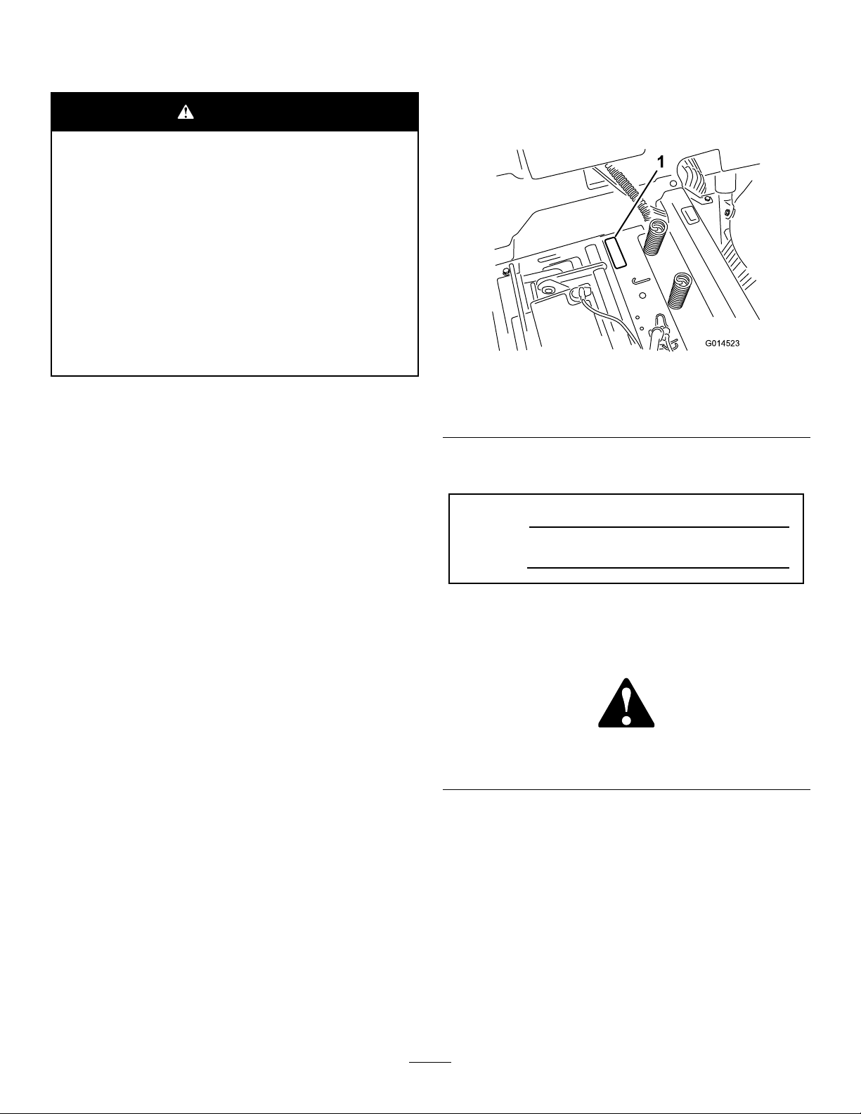
yourproductready.Figure1identiesthelocationofthe
modelandserialnumbersontheproduct.Writethenumbers
inthespaceprovided.
Figure1
Undertheseat
ItisaviolationofCaliforniaPublicResourceCode
Section4442or4443touseoroperatetheengineonany
forest-covered,brush-covered,orgrass-coveredlandunless
theengineisequippedwithasparkarrester,asdenedin
Section4442,maintainedineffectiveworkingorderorthe
engineisconstructed,equipped,andmaintainedforthe
preventionofre.
Thegrossornethorsepowerofthisenginewaslaboratory
ratedbytheenginemanufacturerinaccordancewiththe
SocietyofAutomotiveEngineers(SAE)J1940.Ascongured
tomeetsafety,emission,andoperatingrequirements,
theactualenginetorqueonthisclassofmowerwillbe
signicantlylower.
Gotowww .Toro.comtoviewspecicationsonyourmower
model.
Introduction
Thismachineisaride-on,rotary-bladeintendedtobeused
byhomeownersinresidentialapplications.Itisprimarily
designedforcuttinggrassonwell-maintainedlawns.Itisnot
designedforcuttingbrush,mowinggrassandothergrowth
alongsidehighways,orforagriculturaluses.
1.Modelandserial-numberplate
Writetheproductmodelandserialnumbersinthespace
below:
ModelNo.
SerialNo.
Thismanualidentiespotentialhazardsandhassafety
messagesidentiedbythesafetyalertsymbol(Figure2),
whichsignalsahazardthatmaycauseseriousinjuryordeath
ifyoudonotfollowtherecommendedprecautions.
Figure2
1.Safety-alertsymbol
Thismanualuses2wordstohighlightinformation.
Importantcallsattentiontospecialmechanicalinformation
andNoteemphasizesgeneralinformationworthyofspecial
attention.
Readthisinformationcarefullytolearnhowtooperateand
maintainyourproductproperlyandtoavoidinjuryand
productdamage.Youareresponsibleforoperatingthe
productproperlyandsafely.
YoumaycontactTorodirectlyatwww .Toro.comforproduct
safetyandoperationtrainingmaterials,accessoryinformation,
helpndingadealer,ortoregisteryourproduct.
©2015—TheToro®Company
8111LyndaleAvenueSouth
Bloomington,MN55420
Contactusatwww.Toro.com.
2
PrintedintheUSA
AllRightsReserved
Page 3

Contents
Safety...........................................................................4
SafeOperatingPractices...........................................4
Model74650...........................................................6
Model74655...........................................................6
SlopeIndicator.......................................................7
SafetyandInstructionalDecals.................................8
ProductOverview.........................................................12
Controls...............................................................12
Operation....................................................................13
AddingFuel...........................................................13
CheckingtheEngine-OilLevel.................................14
BreakinginaNewMachine......................................14
ThinkSafetyFirst...................................................15
UnderstandingtheSafety-InterlockSystem................15
TestingtheSafety-InterlockSystem...........................16
StartingtheEngine.................................................16
OperatingtheBlades...............................................16
StoppingtheEngine...............................................17
DrivingtheMachine...............................................17
StoppingtheMachine.............................................19
AdjustingtheHeightofCut.....................................19
PositioningtheSeat................................................20
AdjustingtheMotion-ControlLevers........................20
PushingtheMachinebyHand..................................20
ConvertingtoSideDischarge...................................21
ConvertingtoSideDischarge...................................22
TransportingtheMachine........................................23
LoadingtheMachine..............................................23
OperatingTips......................................................25
Maintenance.................................................................26
RecommendedMaintenanceSchedule(s)......................26
PremaintenanceProcedures........................................27
RaisingtheSeat......................................................27
ReleasingtheMower-DeckCurtain...........................27
Lubrication...............................................................27
GreasingtheBearings.............................................27
EngineMaintenance..................................................28
ServicingtheAirCleaner.........................................28
ServicingtheEngineOil..........................................29
ServicingtheSparkPlug..........................................31
CleaningtheBlowerHousing...................................32
FuelSystemMaintenance...........................................33
ReplacingtheIn-LineFuelFilter...............................33
ElectricalSystemMaintenance....................................34
ChargingtheBattery...............................................34
ServicingtheFuses.................................................35
DriveSystemMaintenance.........................................36
CheckingtheTirePressure......................................36
ReleasingtheElectricBrake.....................................36
MowerMaintenance...................................................37
ServicingtheCuttingBlades.....................................37
LevelingtheMowerDeck........................................39
RemovingtheMower..............................................41
InstallingtheMower...............................................42
ReplacingtheGrassDeector..................................43
MowerBeltMaintenance............................................44
ServicingtheMowerBelt.........................................44
Cleaning...................................................................45
WashingtheUndersideoftheMower........................45
Storage........................................................................46
CleaningandStoringtheMachine.............................46
Troubleshooting...........................................................48
Schematics...................................................................50
3
Page 4

Safety
•Donotoperatethemachinewhileill,tired,orunderthe
inuenceofalcoholordrugs.
ThismachinehasbeendesignedinaccordancewithENISO
5395:2013.
Toreducethepotentialforinjury,complywiththese
safetyinstructionsandalwayspayattentiontothe
safetyalertsymbol,whichmeansCaution,Warning,or
Danger—"personalsafetyinstruction."Failuretocomply
withtheinstructionmayresultinpersonalinjuryordeath.
SafeOperatingPractices
Thisproductiscapableofamputatinghandsandfeetand
throwingobjects.Alwaysfollowallsafetyinstructionsto
avoidseriousinjuryordeath.
GeneralOperation
•Read,understand,andfollowallinstructionsinthe
Operator'sManualandonthemachinebeforestarting.
•Donotplaceyourhandsorfeetnearrotatingpartsor
underthemachine.Keepclearofthedischargeopening
atalltimes.
•Allowonlyresponsibleadultswhoarefamiliarwiththe
instructionstooperatethemachine.
•Cleartheareaofobjectssuchasrocks,toys,wire,etc.,
whichcouldbepickedupandthrownbytheblade.
•Besuretheareaisclearofotherpeoplebeforemowing.
Stopthemachineifanyoneentersthearea.
•Nevercarrypassengers.
•Donotmowinreverseunlessabsolutelynecessary.
Alwayslookdownandbehindbeforeandwhilebacking
up.
•Beawareofthemowerdischargedirectionanddonot
pointitatanyone.Avoiddischargingmaterialagainsta
wallorobstruction.Materialmayricochetbacktoward
you.Stoptheblade(s)whencrossinggravelsurfaces.
•Donotoperatethemachinewithoutdeector,discharge
coverorentiregrasscollectionsysteminplaceand
working.
•Bealert,slowdownandusecautionwhenmakingturns.
Lookbehindandtothesidebeforechangingdirections.
•Neverleavearunningmachineunattended.Alwaysturn
offtheblades,settheparkingbrake,shutofftheengine,
andremovethekeybeforedismountingthemachine.
•Turnoffthebladeswhennotmowing.Shutoffthe
engine,waitforallpartstocometoacompletestopand
removethekeybeforecleaningthemachine,removing
thegrasscatcheroruncloggingthedischargechute.
•Operatethemachineonlyindaylightorgoodarticial
light.
•Watchfortrafcwhenoperatingnearorcrossing
roadways.
•Useextracarewhenloadingorunloadingthemachine
intoatrailerortruck.
•Wearappropriateclothingincludingeyeprotectionand
substantial,slip-resistantshoes.Tiebacklonghair.Do
notwearjewelry.
•Alwaysfollowtherecommendationsforanyapplication
ofcounterweights.
•Lightningcancausesevereinjuryordeath.Iflightning
isseenorthunderisheardinthearea,donotoperate
themachine;seekshelter.
SlopeOperation
Slopesareamajorfactorrelatedtolossofcontroland
tip-overaccidents,whichcanresultinsevereinjuryordeath.
Operationonallslopesrequiresextracaution.Ifyoucannot
backuptheslopeorifyoufeeluneasyonit,donotmowit.
•Donotmowslopesgreaterthan15degrees.
•Watchforditches,holes,rocks,dips,andrisesthatchange
theoperatingangle,asroughterraincouldoverturnthe
machine.
•Choosealowgroundspeedsothatyouwillnothaveto
stopwhileoperatingonaslope.
•Donotmowslopeswhengrassiswet.Slippery
conditionsreducetractionandcouldcauseslidingand
lossofcontrol.
•Alwayskeepthedrivewheelsengagedwhengoingdown
slopes.
•Reducespeedanduseextremecautiononslopes.
•Donotmakesuddenturnsorrapidspeedchanges.
•Removeormarkobstaclessuchasrocks,treelimbs,etc.
fromthemowingarea.Tallgrasscanhideobstacles.
•Avoidsuddenstartswhenmowinguphillbecausethe
mowermaytipbackwards.
•Beawarethatlossoftractionmayoccurgoingdownhill.
Weighttransfertothefrontwheelsmaycausedrive
wheelstoslipandcauselossofbrakingandsteering.
•Alwaysavoidsuddenstartingorstoppingonaslope.If
thetireslosetraction,stopthemachine,disengagethe
bladesandproceedslowlyoffdowntheslope.
•Useextremecarewithgrasscatchersorotherattachments.
Thesecanchangethestabilityofthemachineandcause
lossofcontrol.
•Donottrytostabilizethemachinebyputtingyourfoot
ontheground.
4
Page 5

•Donotmowneardrop-offs,ditches,steepbanksor
water.Wheelsdroppingoveredgescancauserollovers,
whichmayresultinseriousinjury,deathordrowning.
•Useawalkbehindmowerand/orahandtrimmernear
drop-offs,ditches,steepbanksorwater.
Children
Tragicaccidentscanoccuriftheoperatorisnotalerttothe
presenceofchildren.Childrenareoftenattractedtothe
machineandthemowingactivity.Neverassumethatchildren
willremainwhereyoulastsawthem.
•Keepchildrenoutofthemowingareaandunderthe
watchfulcareofanotherresponsibleadult,notthe
operator.
•Bealertandturnthemachineoffifchildrenenterthe
area.
•Beforeandwhilebackingorchangingdirection,look
behind,down,andside-to-sideforsmallchildren.
•Nevercarrychildrenonthemachine,evenwiththe
bladesoff.Childrenmayfalloffandbeseriouslyinjured
orinterferewithsafeoperationofthemachine.
•Childrenwhohavebeengivenridesinthepastmay
suddenlyappearinthemowingareaforanotherrideand
berunoverorbackedoverbythemower.
•Neverallowchildrentooperatethemachine.
•Useextracarewhenapproachingblindcorners,shrubs,
trees,theendofafenceorotherobjectsthatmayobscure
vision.
SafeHandlingofGasoline
Toavoidpersonalinjuryorpropertydamage,useextracare
whenhandlinggasolineandotherfuels.Theyareammable
andthevaporsareexplosive.
•Extinguishallcigarettes,cigars,pipesandothersources
ofignition.
•Useonlyanapprovedcontainer.
•Neverremovethefuelcaporaddfuelwhentheengineis
running.Allowtheenginetocoolbeforerefueling.
•Neverrefuelthemachineindoors.
•Neverstorethemachineorfuelcontainerinsidewhere
thereisanopename,suchasnearawaterheateror
furnace.
•Neverllcontainersinsideavehicleoronatruckor
trailerwithaplasticliner.Alwaysplacecontainersonthe
groundawayfromyourvehiclebeforelling.
•Removefuel-poweredequipmentfromthetruckortrailer
andrefuelitontheground.Ifthisisnotpossible,then
refuelsuchequipmentwithaportablecontainer,rather
thanfromagasolinedispensernozzle.
•Keepthenozzleincontactwiththerimofthefueltank
orcontaineropeningatalltimesuntilthefuelingis
complete.Donotuseanozzlelock-opendevice.
•Ifyouspillfuelonclothing,changeyourclothing
immediately.
•Neveroverllthefueltank.Replacethefuelcapand
tightenitsecurely.
TowingSafety
•Donotattachtowedequipmentexceptatthehitchpoint.
•Followtheattachmentmanufacturer'srecommendation
forweightlimitsfortowedequipmentandtowingon
slopes.Towedweightmustnotexceedtheweightof
themachine,operator,andballast.Usecounterweights
orwheelweightsasdescribedintheattachment,orin
towingthemachineOperator’sManual.
•Neverallowchildrenorothersinorontowedequipment.
•Onslopes,theweightofthetowedequipmentmaycause
lossoftraction,increasedriskofrollover,andlossof
control.Reducethetowedweightandslowdown.
•Thestoppingdistanceincreaseswiththeweightofthe
towedload.Travelslowlyandallowextradistancetostop.
•Makewideturnstokeeptheattachmentclearofthe
machine.
5
Page 6

GeneralService
Measuredvibrationlevelforrighthand=1.9m/s
2
•Neveroperateamachineinsideaclosedarea.Engine
exhaustcontainscarbonmonoxide,whichisanodorless,
deadlypoisonthatcankillyou.
•Keepnutsandboltstight,especiallythebladeattachment
bolts.Keepequipmentingoodcondition.
•Neverinterferewiththeintendedfunctionofasafety
deviceortoreducetheprotectionprovidedbyasafety
device.Checktheirproperoperationregularly.
•Keepthemachinefreeofgrass,leaves,orotherdebris
buildup.Cleanupoilorfuelspillsandfuel-soakeddebris.
Allowthemachinetocoolbeforestoring.
•Stopandinspecttheequipmentifyoustrikeanobject.
Repair,ifnecessary,beforerestarting.
•Nevermakeanyadjustmentsorrepairswiththeengine
running.
•Grasscatchercomponentsaresubjecttowear,damage
anddeterioration,whichcouldexposemovingpartsor
allowobjectstobethrown.Frequentlycheckcomponents
andreplacewithmanufacturers'recommendedparts,
whennecessary.
•Mowerbladesaresharpandcancut.Wraptheblade(s)or
wearthickly-paddedgloves,anduseextracautionwhen
servicingthem.
•Checkforproperbrakeoperationfrequently .Adjustand
serviceasrequired.
•Maintainorreplacesafetyandinstructiondecalsas
necessary.
UncertaintyValue(K)=1.0m/s
Measuredvaluesweredeterminedaccordingtotheprocedures
outlinedinENISO5395:2013.
2
WholeBodyVibration
Measuredvibrationlevel=0.62m/s
UncertaintyValue(K)=0.31m/s
Measuredvaluesweredeterminedaccordingtotheprocedures
outlinedinENISO5395:2013.
2
2
Model74655
SoundPressure
Thisunithasasoundpressurelevelattheoperator’searof89
dBA,whichincludesanUncertaintyValue(K)of1dBA.
Soundpowerlevelwasdeterminedaccordingtothe
proceduresoutlinedinENISO5395:2013.
SoundPower
Thisunithasaguaranteedsoundpowerlevelof100dBA,
whichincludesanUncertaintyValue(K)of1dBA.
Soundpowerlevelwasdeterminedaccordingtothe
proceduresoutlinedinISO11094.
•UseonlygenuineTororeplacementpartstoensurethat
originalstandardsaremaintained.
Model74650
SoundPressure
Thisunithasasoundpressurelevelattheoperator’searof87
dBA,whichincludesanUncertaintyValue(K)of1dBA.
Soundpowerlevelwasdeterminedaccordingtothe
proceduresoutlinedinENISO5395:2013.
SoundPower
Thisunithasaguaranteedsoundpowerlevelof100dBA,
whichincludesanUncertaintyValue(K)of1dBA.
Soundpressurelevelwasdeterminedaccordingtothe
proceduresoutlinedinISO11094.
Hand/ArmVibration
Measuredvibrationlevelforlefthand=2.1m/s
2
Hand/ArmVibration
Measuredvibrationlevelforlefthand=3.4m/s
Measuredvibrationlevelforrighthand=2.4m/s
UncertaintyValue(K)=1.7m/s
Measuredvaluesweredeterminedaccordingtotheprocedures
outlinedinENISO5395:2013.
2
WholeBodyVibration
Measuredvibrationlevel=0.73m/s
UncertaintyValue(K)=0.37m/s
Measuredvaluesweredeterminedaccordingtotheprocedures
outlinedinENISO5395:2013.
2
2
2
2
6
Page 7
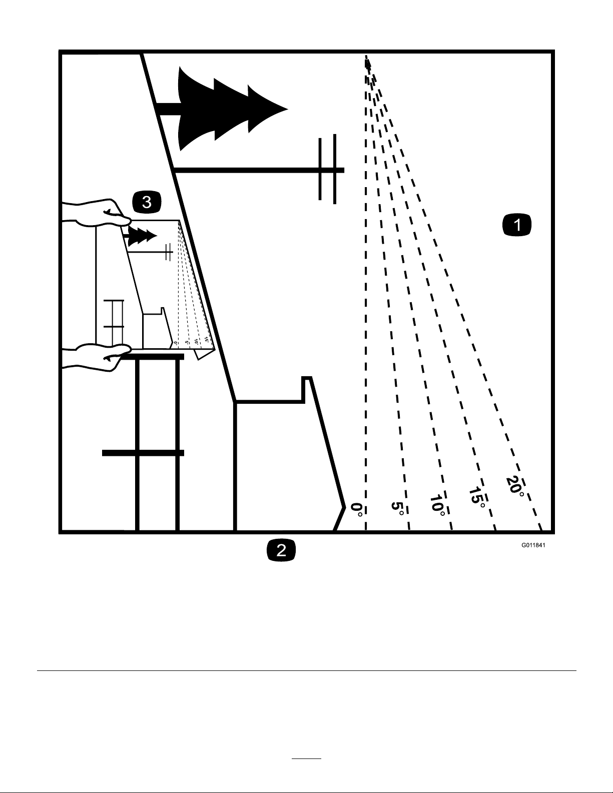
SlopeIndicator
G011841
Figure3
Thispagemaybecopiedforpersonaluse.
1.Themaximumslopeyoucansafelyoperatethemachineonis15degrees.Usetheslopecharttodeterminethedegreeofslope
ofhillsbeforeoperating.Donotoperatethismachineonaslopegreaterthan15degrees.Foldalongtheappropriateline
tomatchtherecommendedslope.
2.Alignthisedgewithaverticalsurface,atree,building,fencepole,etc.
3.Exampleofhowtocompareslopewithfoldededge.
7
Page 8
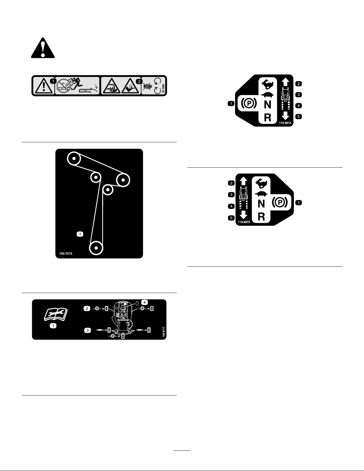
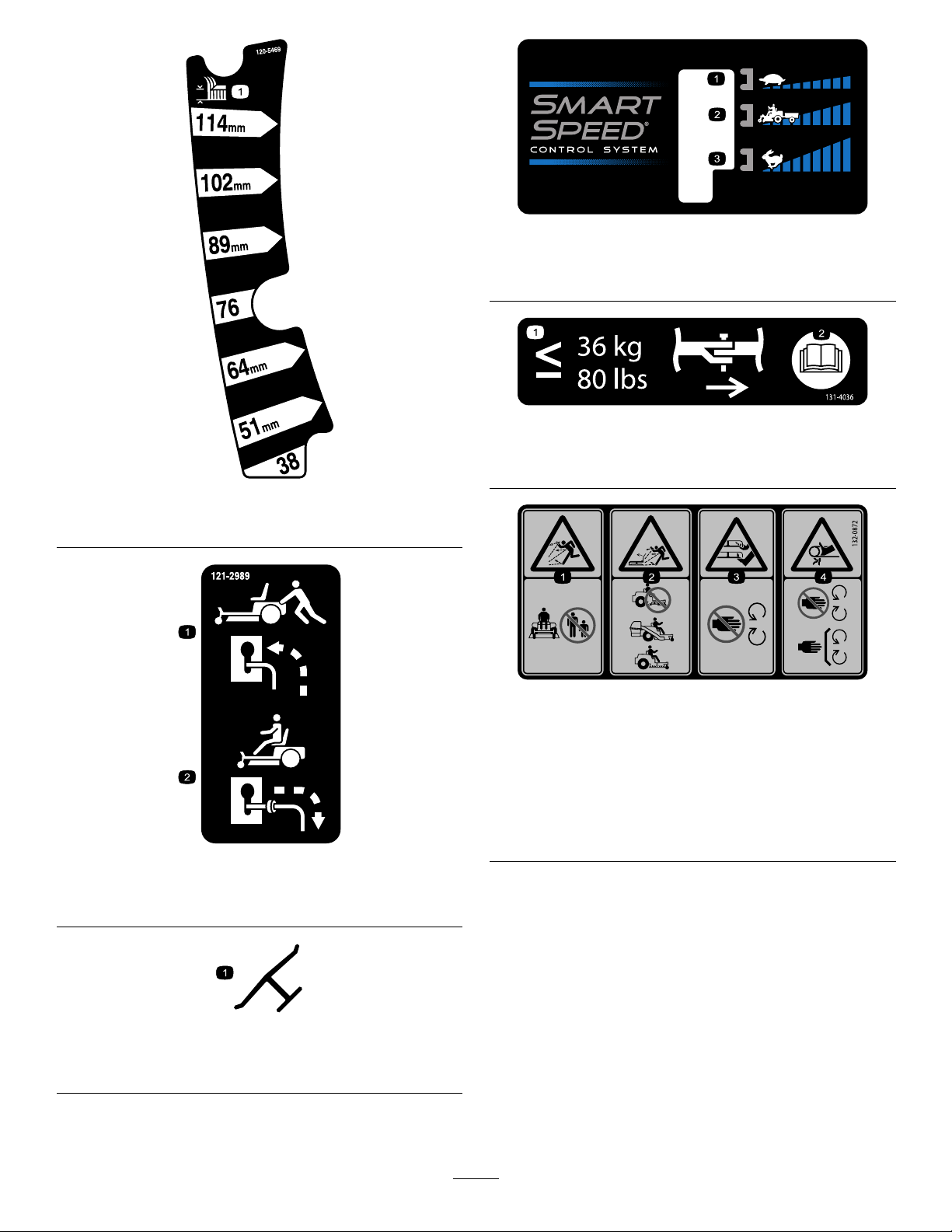
SafetyandInstructionalDecals
Safetydecalsandinstructionsareeasilyvisibletotheoperatorandarelocatednearanyareaofpotential
danger.Replaceanydecalthatisdamagedorlost.
93-7009
1.Warning—don'toperatethemowerwiththedeectorupor
removed;keepthedeectorinplace.
2.Cutting/dismembermenthazardofhandorfoot,mower
blade—stayawayfrommovingparts.
119-8814
1.PARKINGposition4.NEUTRAL
2.FAST5.REVERSE
3.SLOW
105-7015
ForModelswith107cm(42-inch)Decks
1.Beltrouting
106-8717
1.Readtheinstructionsbeforeservicingorperforming
maintenance.
2.Checktirepressureevery25operatinghours.
3.Greaseevery25operatinghours.
4.Engine
119-8815
1.PARKINGposition4.NEUTRAL
2.FAST5.REVERSE
3.SLOW
8
Page 9
131-3948
131-3948
1.Heightofcut
1.Slow
2.Towing
3.Fast
131-4036
1.Maximumdrawbarpull36
kg(80lb)
2.ReadtheOperator's
Manual.
120-5469
132-0872
121-2989
1.Bypassleverpositionfor
pushingthemachine
2.Bypassleverpositionfor
operatingthemachine
Manufacturer'sMark
1.Indicatesthebladeisidentiedasapartfromtheoriginal
machinemanufacturer.
1.Thrownobject
hazard—keepbystanders
awayfromthemachine.
2.Thrownobjecthazard,
raisedbafe—donot
operatethemachinewith
anopendeck;usea
baggerorabafe.
3.Severinghazardofhand
orfoot—keepawayfrom
movingparts.
4.Entanglement
hazard—keepaway
frommovingparts;keep
allguardsandshieldsin
place.
9
Page 10

BatterySymbols
Someorallofthesesymbolsareonyourbattery
1.Explosionhazard
2.Nore,opename,or
smoking.
3.Causticliquid/chemical
burnhazard
4.Weareyeprotection9.Flusheyesimmediately
5.ReadtheOperator's
Manual.
6.Keepbystandersasafe
7.Weareyeprotection;
8.Batteryacidcancause
10.Containslead;donot
distancefromthebattery.
explosivegasescan
causeblindnessandother
injuries
blindnessorsevereburns.
withwaterandgetmedical
helpfast.
discard.
121-0771
1.Choke4.SLOW
2.FAST
3.Continuous-variablesetting
10
5.Powertake-off(PTO)—Blade-controlswitch
Page 11
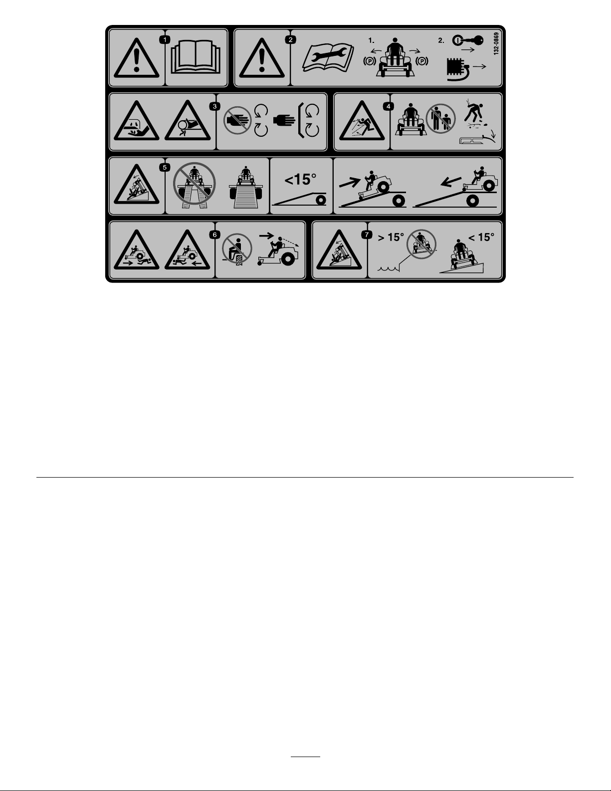
132-0869
1.Warning—readthe
Operator'sManual.
2.Warning—beforeservicing,
engagetheparkingbrake,
removethekeyandthe
sparkplugconnection.
3.Cuttinghazardofhand,
mowerblade;pinching
hazardofhand,belt—keep
handsandfeetawayfrom
movingparts;keepall
guardsandshieldsinplace.
4.Thrownobject
hazard—keepbystanders
awayfromthemachine;
removedebrisfromthe
areabeforemowing;keep
thedeectorshielddown.
5.Ramptipping
hazard—whenloading
ontoatrailer,donotuse
dualramps;onlyusea
singlerampwideenough
forthemachineandthat
hasaninclinelessthan
15degrees;backupthe
ramp(inreverse)anddrive
forwardofftheramp.
6.Bodilyharmhazard—no
riders;lookbehindyou
whenmowinginreverse.
7.Tippinghazardon
slopes—donotuseon
slopesnearopenwater;do
notuseonslopesgreater
than15degrees.
11
Page 12
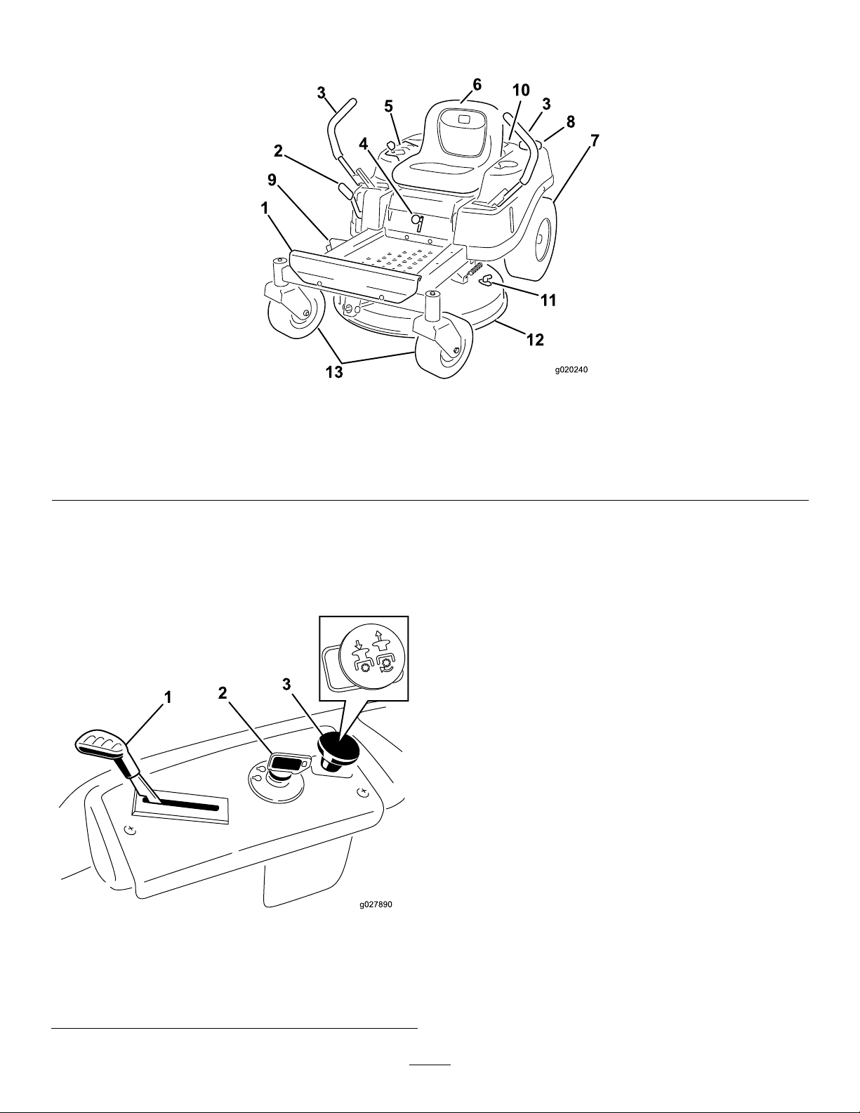
ProductOverview
g020240
1
2
3
4
5
6
7
8
10
11
12
13
9
3
Figure4
1.Footrest
2.Height-of-cutlever6.Operatorseat
3.Motion-controllever7.Reardrivewheel
4.Smart-speedlever
5.Controlpanel9.Deector
8.Fuel-tankcap12.Mowerdeck
Controls
BecomefamiliarwithallcontrolsinFigure4andFigure5
beforeyoustarttheengineandoperatethemachine.
13.Frontcasterwheels
10.Engine
11.Washouttting
IgnitionSwitch
Theignitionswitchhas3positions:OFF,RUN,andSTART.
ThekeywillturntoSTARTandmovebacktoRUNupon
release.TurningthekeytotheOFFpositionwillshutoff
theengine;however,alwaysremovethekeywhenleaving
themachinetopreventsomeonefromaccidentallystarting
theengine(Figure5).
Throttle/ChokeControl
Thethrottleandchokearecombinedinto1control
lever.Thethrottlecontrolstheenginespeedandhasa
continuous-variablesettingfromtheSLOWpositiontothe
FASTposition.Engagethechokebymovingtheleverpast
theFASTsettinguntilitstops(Figure5).
Itmaybenecessarytoholdtheleveragainstthestop,inthe
chokeposition,whiletryingtostarttheengine.
Note:Awarmorhotenginemaynotrequirechoking.
1.Throttle/Choke
2.Ignitionswitch
Figure5
ControlPanel
3.Blade-controlswitch
(powertakeoff)
Blade-ControlSwitch(PowerTakeoff)
Theblade-controlswitch,representedbyapowertake-off
(PTO)symbol,engagesanddisengagespowertothemower
blades(Figure5).
12
Page 13
Motion-ControlLeversandPark
G014521
1
Position
Themotion-controlleversarespeed-sensitivecontrolsof
independent-wheelmotors.Movingaleverforwardor
backwardturnsthewheelonthesamesideforwardorin
reverse;wheelspeedisproportionaltotheamountthelever
ismoved.Movethecontrolleversoutwardfromthecenter
tothePARKpositionwhenexitingthemachine(Figure13).
Alwayspositionthemotion-controlleversintothePARK
positionwhenyoustopthemachineorleaveitunattended.
SmartSpeed™ControlSystemLever
TheSmartSpeed™Control-Systemlever,locatedbelowthe
operatingposition,givestheoperatorachoicetodrivethe
machineat3speedranges—trim,tow ,andmow(Figure16).
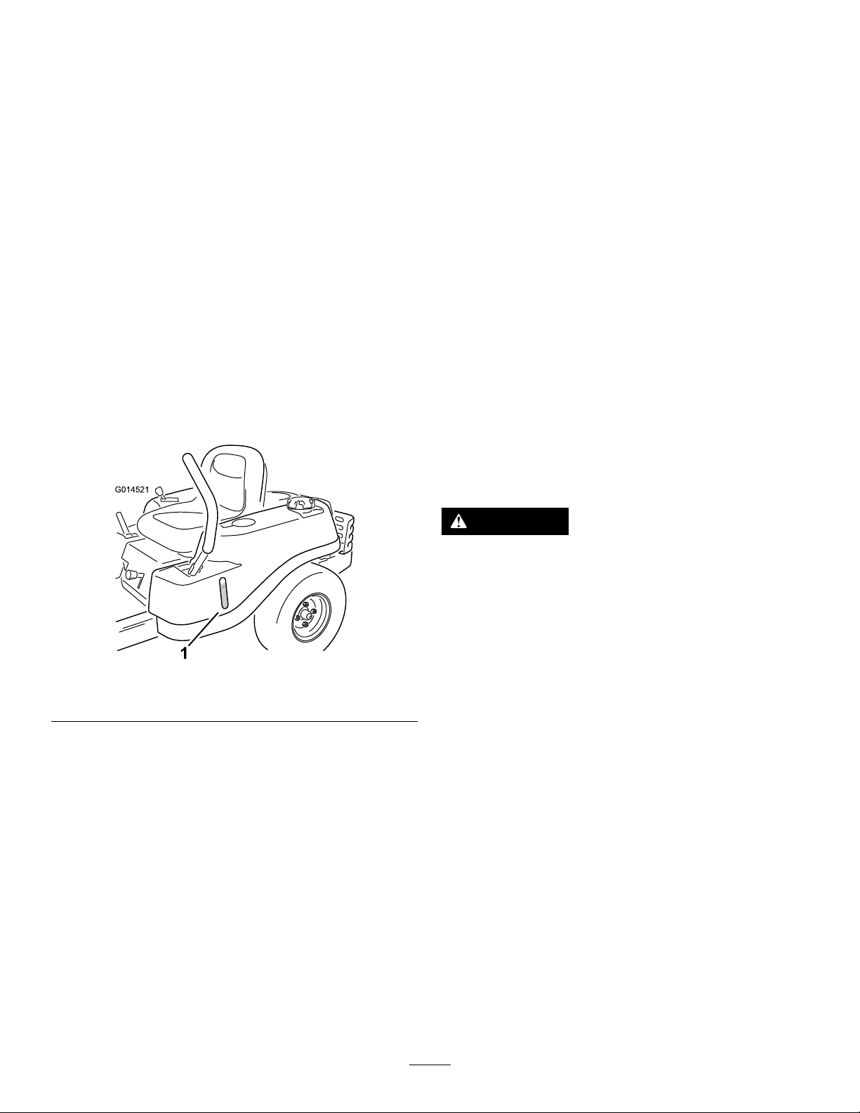
Fuel-PresenceWindow
Thefuelwindowlocatedontheleft-handsideofthemachine,
canbeusedtoverifythepresenceofgasolineinthetank
(Figure6).
Operation
Note:Determinetheleftandrightsidesofthemachine
fromthenormaloperatingposition.
AddingFuel
•Forbestresults,useonlyclean,fresh(lessthan30days
old),unleadedgasolinewithanoctaneratingof87or
higher((R+M)/2ratingmethod).
•Ethanol:Gasolinewithupto10%ethanol(gasohol)
or15%MTBE(methyltertiarybutylether)byvolume
isacceptable.EthanolandMTBEarenotthesame.
Gasolinewith15%ethanol(E15)byvolumeisnot
approvedforuse.Neverusegasolinethatcontains
morethan10%ethanolbyvolume,suchasE15
(contains15%ethanol),E20(contains20%ethanol),or
E85(containsupto85%ethanol).Usingunapproved
gasolinemaycauseperformanceproblemsand/orengine
damagewhichmaynotbecoveredunderwarranty.
•Donotusegasolinecontainingmethanol.
•Donotstorefueleitherinthefueltankorfuelcontainers
overthewinterunlessafuelstabilizerisused.
Figure6
1.Fuel-presencewindow
Height-of-CutLever
Theheight-of-cutleverallowstheoperatortolowerand
raisethedeckfromtheseatedposition.Whentheleveris
movedup(towardtheoperator),thedeckisraisedfromthe
ground,andwhenmoveddown(awayfromtheoperator),it
isloweredtowardtheground.Onlyadjusttheheight-of-cut
whilethemachineisnotmoving.
•Donotaddoiltogasoline.
DANGER
Incertainconditions,gasolineisextremely
ammableandhighlyexplosive.Areorexplosion
fromgasolinecanburnyouandothersandcan
damageproperty.
•Fillthefueltankoutdoors,inanopenarea,
whentheengineiscold.Wipeupanygasoline
thatspills.
•Neverllthefueltankinsideanenclosedtrailer.
•Donotllthefueltankcompletelyfull.Add
gasolinetothefueltankuntilthelevelis6to13
mm(1/4to1/2inch)belowthebottomofthe
llerneck.Thisemptyspaceinthetankallows
gasolinetoexpand.
•Neversmokewhenhandlinggasoline,andstay
awayfromanopenameorwheregasoline
fumesmaybeignitedbyaspark.
•Storegasolineinanapprovedcontainerand
keepitoutofthereachofchildren.Neverbuy
morethana30-daysupplyofgasoline.
•Donotoperatewithoutentireexhaustsystemin
placeandinproperworkingcondition.
13
Page 14
DANGER
g027243
A
B
E
D
C
Incertainconditionsduringfueling,static
electricitycanbereleasedcausingasparkwhich
canignitethegasolinevapors.Areorexplosion
fromgasolinecanburnyouandothersandcan
damageproperty.
•Alwaysplacegasolinecontainersontheground
awayfromyourvehiclebeforelling.
•Donotllgasolinecontainersinsideavehicleor
onatruckortrailerbedbecauseinteriorcarpets
orplastictruckbedlinersmayinsulatethe
containerandslowthelossofanystaticcharge.
•Whenpractical,removegas-poweredequipment
fromthetruckortrailerandrefueltheequipment
withitswheelsontheground.
•Ifthisisnotpossible,thenrefuelsuch
equipmentonatruckortrailerfromaportable
container,ratherthanfromagasolinedispenser
nozzle.
•Ifagasolinedispensernozzlemustbeused,
keepthenozzleincontactwiththerimofthe
fueltankorcontaineropeningatalltimesuntil
fuelingiscomplete.
Note:Afuelstabilizer/conditionerismosteffective
whenmixedwithfreshgasoline.T ominimizethechance
ofvarnishdepositsinthefuelsystem,usefuelstabilizer
atalltimes.
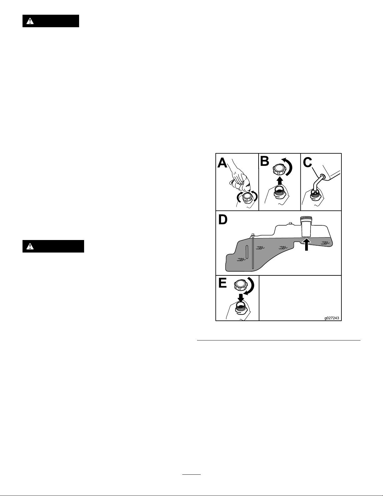
FillingtheFuelTank
Note:Ensurethattheengineisshutoffandthemotion
controlsareintheparkedposition.
Note:Youcanusethefuelwindowtoverifythepresenceof
gasolinebeforellingthetank(Figure7).
Important:Donotoverllfueltank.Fillthefueltank
tothebottomofthellerneck.Theemptyspaceinthe
tankallowsthefueltoexpand.Overllingmayresultin
fuelleakage,damagetotheengine,ordamagetothe
emissionssystem.
WARNING
Gasolineisharmfulorfatalifswallowed.Long-term
exposuretovaporscancauseseriousinjuryand
illness.
•Avoidprolongedbreathingofvapors.
•Keepfaceawayfromnozzleandgastankor
conditionerbottleopening.
•Avoidcontactwithskin;washoffspillagewith
soapandwater.
UsingStabilizer/Conditioner
Useafuelstabilizer/conditionerinthemachinetoprovide
thefollowingbenets:
•Keepsgasolinefreshduringstorageof90daysorless.
Forlongerstorageitisrecommendedthatthefueltank
bedrained.
•Cleanstheenginewhileitruns
•Eliminatesgum-likevarnishbuildupinthefuelsystem,
whichcauseshardstarting
Important:Donotusefueladditivescontaining
methanolorethanol.
Addthecorrectamountofgasstabilizer/conditionerto
thegas.
Figure7
CheckingtheEngine-OilLevel
Beforeyoustarttheengineandusethemachine,check
theoillevelintheenginecrankcase;refertoCheckingthe
Engine-OilLevel(page29).
BreakinginaNewMachine
Newenginestaketimetodevelopfullpower.Mowerdecks
anddrivesystemshavehigherfrictionwhennew,placing
additionalloadontheengine.Allow40to50hoursof
break-intimefornewmachinestodevelopfullpowerand
bestperformance.
14
Page 15
ThinkSafetyFirst
G009027
1
2
CAUTION
Pleasereadallsafetyinstructionsandsymbolsinthesafety
section.Knowingthisinformationcouldhelpyouor
bystandersavoidinjury.
DANGER
Operatingthemachineonwetgrassorsteepslopes
cancauseslidingandlossofcontrol.
•Donotoperateonslopesgreaterthan15degrees.
•Reducespeedanduseextremecautionon
slopes.
•Donotoperatethemachinenearwater.
DANGER
Wheelsdroppingoveredgescancauserollovers,
whichmayresultinseriousinjury,death,or
drowning.
Donotoperatethemachineneardrop-offs.
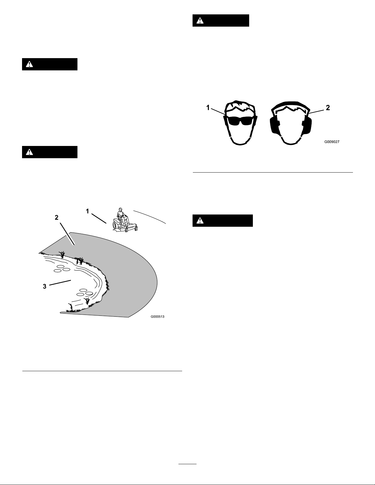
Thismachineproducessoundlevelsinexcessof
85dBAattheoperator’searandcancausehearing
lossthroughextendedperiodsofexposure.
Wearhearingprotectionwhenoperatingthis
machine.
Theuseofprotectiveequipmentforeyes,ears,hands,feet,
andheadisrecommended.
Figure9
1.Weareyeprotection.2.Wearhearingprotection.
Understandingthe Safety-InterlockSystem
1.Safezone—usethe
TimeCutterhere
2.Useawalk-behindmower
and/orhandtrimmernear
drop-offsandwater.
Figure8
3.Water
WARNING
Ifthesafety-interlockswitchesaredisconnectedor
damaged,themachinecouldoperateunexpectedly,
causingpersonalinjury.
•Donottamperwiththeinterlockswitches.
•Checktheoperationoftheinterlockswitches
dailyandreplaceanydamagedswitchesbefore
operatingthemachine.
Thesafety-interlocksystemisdesignedtopreventtheengine
fromstartingunless:
•Thebladesaredisengaged.
•Themotion-controlleversareinthePARKposition.
Thesafety-interlocksystemalsoisdesignedtoshutoffthe
enginewheneverthecontrolleversareoutofthePARK
positionandyourisefromtheseat.
15
Page 16
TestingtheSafety-Interlock
g027535
B
C
D
E
A
G
F
StartingtheEngine
System
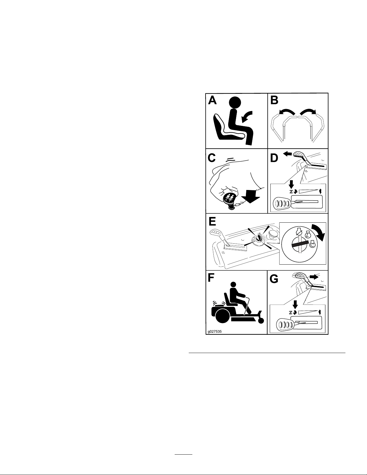
Testthesafety-interlocksystembeforeyouusethemachine
eachtime.Ifthesafetysystemdoesnotoperateasdescribed
below,haveanAuthorizedServiceDealerrepairthesafety
systemimmediately.
1.Whilesittingontheseat,withthecontrolleversinthe
PARKposition,andmovetheblade-controlswitchto
theONposition.Trystartingtheengine;theengine
shouldnotcrank.
2.Whilesittingontheseat,movetheblade-controlswitch
totheOFFposition.Moveeithermotioncontrol
levertothecenter,unlockedposition.Trystartingthe
engine;theengineshouldnotcrank.Repeatwiththe
othermotion-controllever.
3.Whilesittingontheseat,movethebladecontrolswitch
totheOFFposition,andlockthemotion-controllevers
inthePARKposition.Starttheengine.Whilethe
engineisrunning,engagetheblade-controlswitch,and
riseslightlyfromtheseat;theengineshouldstop.
4.Whilesittingontheseat,movetheblade-controlswitch
totheOFFposition,andlockthemotion-controllevers
inthePARKposition.Starttheengine.Whilethe
engineisrunning,movethemotion-controlleversto
thecenter,unlockedposition,engagetheblade-control
switch,andriseslightlyfromtheseat;theengine
shouldstop.
Important:Donotengagethestarterformorethan
5secondsatatime.Engagingthestartermotorfor
morethan5secondscandamagethestartermotor.If
theenginefailstostart,wait10secondsbeforeoperating
theenginestarteragain.
Note:Itmaybenecessarytoholdtheleveragainstthestop,
inthechokeposition,whiletryingtostarttheengine(Figure
10).
Figure10
OperatingtheBlades
Theblade-controlswitchengagesanddisengagespower
tothemowerblades.Thisswitchcontrolspowertoany
attachmentsthatdrawpowerfromtheengine,includingthe
mowerdeckandcuttingblades.
EngagingtheBlades
Important:Donotengagethebladeswhenparkedin
tallgrass;beltorclutchdamagecanoccur.
16
Page 17

Note:Alwaysengagethebladeswiththethrottleinthe
g027537
B
A
C
1
g027538
FASTposition.
DrivingtheMachine
Drivingthemachinebenetsfromanunderstandingof
whatzero-turn-radiusmowermeans.Thedrivewheelsturn
independently,poweredbyhydraulicmotorsoneachaxle;
hence1sidecanturninreversewhiletheotherturnsforward,
causingthemachinetospinratherthanturn.Thisvastly
improvesthemachinemaneuverabilitybutmayrequiresome
adjustmentifyouareunfamiliar.
WARNING
Themachinecanspinveryrapidly.Y oumaylose
controlofthemachineandcausepersonalinjuryor
damagetothemachine.
•Usecautionwhenmakingturns.
•Slowthemachinedownbeforemakingsharp
turns.
Figure11
DisengagingtheBlades
Figure12
1.Controlpanel2.Blade-controlswitch—Off
Thethrottlecontrolregulatestheenginespeedasmeasured
inrpm(revolutionsperminute).Placingthethrottlecontrol
intheFASTpositioncanbebestforperformance.Formost
applications,operatethemachineinthefull-throttleposition.
StoppingtheEngine
1.Disengagethebladesbymovingtheblade-control
switchtotheOFFposition(Figure12).
2.MovethethrottlelevertotheFASTposition.
3.TurntheignitionkeytotheOFFpositionandremove
thekey.
Figure13
1.PARKposition4.Backward
2.Center,unlockposition5.Frontofthemachine
3.Forward
17
Page 18

DrivingForward
G008952
G008953
DrivingBackward
Note:Alwaysusecautionwhenbackingupandturning.
1.Movetheleverstothecenter,unlockedposition.
2.Togoforward,slowlypushthemotion-controllevers
forward(Figure14).
Figure14
Togostraight,applyequalpressuretoboth
motion-controllevers(Figure14).
Toturn,releasepressureonthemotion-controllever
towardthedirectionyouwanttoturn(Figure14).
Thefartheryoumovethemotion-controlleversin
eitherdirection,thefasterthemachinemovesinthat
direction.
Tostop,pullthemotion-controlleverstotheNEUTRAL
position.
Note:Alwaysusecautionwhenbackingupandturning.
1.Movetheleverstothecenter,unlockedposition.
2.Togobackward,lookbehindyouanddown,asyou
slowlypullthemotion-controlleversrearward(Figure
15).
Figure15
Togostraight,applyequalpressuretoboth
motion-controllevers(Figure15).
Toturn,releasethepressureonthemotion-control
levertowardthedirectionyouwanttoturn.
Tostop,pushthemotion-controlleverstothe
NEUTRALposition.
UsingtheSmartSpeed
TM
Control
System
TheSmartSpeed
operatingposition(Figure16),givestheoperatorachoice
todrivethemachineat3groundspeedranges—trim,tow ,
andmow .
TM
Control-Systemlever,locatedbelowthe
Figure16
1.Smart-speedlever
18
Page 19

Tochangespeeds,dothefollowing:
1.Movethemotion-controlleverstotheNEUTRAL
positionandoutwardtothePARKposition.
2.Disengagetheblade-controlswitch.
WARNING
Childrenorbystandersmaybeinjuredifthey
moveorattempttooperatethemowerwhileitis
unattended.
3.Adjustthelevertothedesiredposition.
Thefollowingareonlyrecommendationsforuse.
Adjustmentsvarybygrasstype,moisturecontent,andthe
heightofthegrass.
Suggested
uses:
ParkingX
Heavy,wet
grass
TrainingX
BaggingX
MulchingX
Normal
mowing
TransportX
Trim
Thisisthelowestspeed.Thesuggestedusesforthisspeed
areasfollows:
TrimTowMow
X
X
•Parking
Alwaysremovetheignitionkeyandmovethe
motion-controlleversoutwardtothePARKposition
whenleavingthemachineunattended,evenifjust
forafewminutes.
AdjustingtheHeightofCut
Note:Thetransportpositionisthehighestheight-of-cut
positionorcuttingheight115mm(4.5inches)asshownin
Figure17.
Heightofcutiscontrolledbytheleverlocatedtotherightof
theoperatingposition(Figure17).
•Heavy,wetgrassmowingconditions
•Training
Tow
Thisisthemediumspeed.Thesuggestedusesforthisspeed
areasfollows:
•Bagging
•Mulching
Mow
Thisisthefastestspeed.Thesuggestedusesforthisspeed
areasfollows:
•Normalmowing
•Transportingthemachine
StoppingtheMachine
Tostopthemachine,movethemotion-controlleversto
theNEUTRALpositionandoutwardtothePARKposition,
disengagetheblade-controlswitch,ensurethethrottleis
betweenhalfandfullthrottle,andturntheignitionkeytooff.
Removethekeyfromtheignitionswitch.
Figure17
19
Page 20

PositioningtheSeat
g027249
B
C
A
g027252
B
A
g017303
1 2
3
MovetheseatforwardorbackwardasshowninFigure18.
Figure18
2.Loosenthelowerboltjustenoughtopivotthecontrol
leverforwardorrearward(Figure19).
3.Tightenbothboltstosecurethecontrolleverinthe
newposition.
4.Repeattheadjustmentfortheothercontrollever.
PushingtheMachinebyHand
Important:Alwayspushthemachinebyhand.Donot
towthemachine,becausedamagemayoccur.
Thismachinehasanelectric-brakemechanism,andtopush
themachine,theignitionkeyneedstobeintheRUNposition.
Thebatteryneedstobechargedandfunctioningforthe
electricbraketobedisengage.
PushingtheMachine
1.Parkthemachineonalevelsurface,anddisengagethe
blade-controlswitch.
2.Movethemotion-controlleversoutwardtothePARK
position,shutofftheengine,andwaitforallmoving
partstostopbeforeleavingtheoperatingposition.
3.Locatethebypassleversontheframeonbothsidesof
theengine.
AdjustingtheMotion-Control Levers
AdjustingtheHeight
Youcanadjustthemotion-controllevershigherorlowerfor
maximumcomfort(Figure19).
Figure19
4.Movethebypassleversforwardthroughthekeyhole
anddowntolocktheminplace(Figure20).
Note:Dothisforeachlever.
5.Movethemotion-controlleversinwardtotheNEUTRAL
positionandturntheignitionkeytotheRUNposition.
Note:Donotstartthemachine.
Note:Youcannowpushthemachinebyhand.
AdjustingtheTilt
Youcanadjustthemotion-controlleversforwardorrearward
foryourcomfort.
1.Loosentheupperboltholdingthecontrollevertothe
control-armshaft.
1.Bypass-leverlocations
2.Leverpositionfor
operatingthemachine
20
Figure20
3.Leverpositionforpushing
themachine
Page 21

6.Whennished,ensurethatthekeyhasbeenreturnedto
theSTOPpositiontoavoiddrainingthebatterycharge.
4.Removethehingepinsecuringthecovertothedeck
(Figure21).
Note:Ifthemachinefailstomove,theelectricbrakemay
stillbeengaged.Ifnecessary,theelectricbrakecanbereleased
manually;refertoReleasingtheElectricBrake(page36).
OperatingtheMachine
Movethebypassleversrearwardthroughthekeyholeand
downtolocktheminplaceasshowninFigure20.
Note:Dothisforeachlever.
ConvertingtoSideDischarge
ForModelswith81cm(32-inch)Mower
Decks
Thismowerdeckhastheoptiontooperateinthe
side-dischargemode.Removethedischargecoverfor
operatingintheside-dischargemode.
RemovingtheDischargeCoverforSide
Discharge
1.Parkthemachineonalevelsurfaceanddisengagethe
blade-controlswitch.
2.Movethemotion-controlleversoutwardtoPARK
position,shutofftheengine,removethekey,and
waitforallmovingpartstostopbeforeleavingthe
operatingposition.
3.Removethewingnutandboltsecuringthecoverin
place(Figure21).
5.Liftthecoveroutandawayfromthedeck.
6.Lowerthegrassdeectoroverthedischargeopening.
Important:Ensurethatthemowerhasahinged
grassdeectorthatdispersesclippingstotheside
anddowntowardtheturf,whileinsidedischarge
mode.
InstallingtheDischargeCoverfor
Mulching
1.Parkthemachineonalevelsurfaceanddisengagethe
blade-controlswitch.
2.Movethemotion-controlleversoutwardtoPARK
position,shutofftheengine,removethekey,and
waitforallmovingpartstostopbeforeleavingthe
operatingposition.
3.Liftthegrassdeectorandplacethedischargecover
overtheopeningontothelowerlipofthemowerand
slideitintothefronthinge(Figure21).
4.Slidethehingepinthroughthehinge(Figure21).
5.Securethedischargecovertothemowerwiththewing
nut(Figure21).
6.Lowerthegrassdeectoroverthedischargeopening.
Note:Retainallofthepartsforfutureuse.
Figure21
1.Grassdeector
2.Dischargecover5.Wingnut
3.Lowerlip
4.Hingepin
21
Page 22

ConvertingtoSideDischarge
G009660
1
2
3
4
5
G005667
1
2
3
ForModelswith107cm(42-inch)
MowerDecks
Themowerdeckandmowerbladesshippedwiththismachine
weredesignedforoptimummulchingandside-discharge
performance.
RemovingtheDischargeCoverforthe
SideDischarge
1.Parkthemachineonalevelsurfaceanddisengagethe
blade-controlswitch.
2.Movethemotion-controlleversoutwardtoPARK
position,shutofftheengine,removethekey,and
waitforallmovingpartstostopbeforeleavingthe
operatingposition.
3.Removethe2boltsandnutsthatsecurethedischarge
covertothemower(Figure22).
Figure23
1.Pivotrod
2.Cutoffbafe(originally
shippedwiththemachine)
8.Torquethefastenerto7to9N•m(14to18ft-lb).
9.Lowerthegrassdeectoroverthedischargeopening.
Important:Ensurethatthemowerhasahinged
grassdeectorthatdispersesclippingstotheside
anddowntowardtheturf,whileinside-discharge
mode.
3.Existingthinnut(3/8inch)
Figure22
1.Capnut(1/4inch)
2.Dischargecover5.Removethecover.
3.Bolt(1/4x2-1/2inches)
4.Removethedischargecover.
5.Liftupthegrassdeectorandlocatethelocknutonthe
deector-pivotrod.
6.Removetheexistingthinnut(3/8inch).
7.Installthecutoffbafetotheexposedpivotrod
(Figure23).
4.Rotatethecoverup.
InstallingtheDischargeCoverfor
Mulching
1.Parkthemachineonalevelsurfaceanddisengagethe
blade-controlswitch.
2.Movethemotion-controlleversoutwardtothePARK
position,shutofftheengine,removethekey,andwait
forallthemovingpartstostopbeforeleavingthe
operatingposition.
3.Removethecutoffbafefromthemowerdeck(Figure
23).
4.Liftthegrassdeectorandslidethetabsontopofthe
dischargecoverunderthegrassdeectorretainingrod.
5.Rotatethedischargecoverdownovertheopening,and
ontothelowerlipofthemower(Figure24).
Note:Usetheexistingthinnut(3/8inch)tosecure
thebafetothemower.
Note:Thecutoffbafewasshippedwiththemachine
asaloosepart.
22
Page 23

Figure24
TransportingtheMachine
Useaheavy-dutytrailerortrucktotransportthemachine.
Ensurethatthetrailerortruckhasallnecessarybrakes,
lighting,andmarkingasrequiredbylaw .Pleasecarefullyread
allthesafetyinstructions.Knowingthisinformationcould
helpyou,yourfamily,pets,orbystandersavoidinjury.
WARNING
Drivingonthestreetorroadwaywithout
turnsignals,lights,reectivemarkings,ora
slow-moving-vehicleemblemisdangerousandcan
leadtoaccidents,causingpersonalinjury.
Donotdrivethemachineonapublicstreetor
roadway.
1.Ifyouareusingatrailer,connectittothetowing
vehicleandconnectthesafetychains.
2.Ifapplicable,connectthetrailerbrakes.
3.Loadthemachineontothetrailerortruck.
4.Shutofftheengine,removethekey,setthebrake,and
closethefuelvalve.
5.Tiedownthemachinenearthefrontcasterwheelsand
therearbumper(Figure25).
1.Dischargecover
2.Capnut(1/4inch)
6.Securethedischargecovertothelowerlipofthe
mowerwith2bolts(1/4x2-1/2inches)and2capnuts
(1/4inch)asshowninFigure24.
Note:Donotovertightenthenuts;thiscoulddistort
thecoverandcausebladecontact.
3.Bolt(1/4x2-1/2inches)
Figure25
LoadingtheMachine
Useextremecautionwhenloadingorunloadingmachines
ontoatraileroratruck.Useafull-widthrampthatiswider
thanthemachineforthisprocedure.Backuptherampand
driveforwarddowntheramp(Figure26).
1.Backthemachineupthe
ramp.
23
Figure26
2.Drivethemachineforward
downtheramp.
Page 24

Important:Donotusenarrowindividualrampsfor
g027996
5
1
2
6
eachsideofthemachine.
Ensuretherampislongenoughsothattheanglewiththe
grounddoesnotexceed15degrees(Figure27).Onat
ground,thisrequiresaramptobeatleast4timesaslongas
theheightofthetrailerortruckbedtotheground.Asteeper
anglemaycausemowercomponentstogetcaughtastheunit
movesfromtheramptothetrailerortruck.Steeperangles
mayalsocausethemachinetotiporlosecontrol.Ifloading
onornearaslope,positionthetrailerortrucksothatitis
onthedownsideoftheslopeandtherampextendsupthe
slope.Thiswillminimizetherampangle.
WARNING
Loadingamachineontoatrailerortruckincreases
thepossibilityoftip-overandcouldcauseserious
injuryordeath.
•Useextremecautionwhenoperatingamachine
onaramp.
•Useonlyafull-widthramp;donotuseindividual
rampsforeachsideofthemachine.
•Donotexceeda15-degreeanglebetweenthe
rampandthegroundorbetweentherampand
thetrailerortruck.
•Ensurethelengthoframpisatleast4timesas
longastheheightofthetrailerortruckbedto
theground.Thiswillensurethatrampangle
doesnotexceed15degreesonatground.
•Backuprampsanddriveforwarddownramps.
•Avoidsuddenaccelerationordecelerationwhile
drivingthemachineonarampasthiscould
causealossofcontroloratip-oversituation.
1.Full-widthrampinstowed
position
2.Sideviewoffull-width
rampinloadingposition
3.Notgreaterthan
15degrees
Figure27
4.Rampisatleast4times
aslongastheheightof
thetrailerortruckbedto
theground
5.H=heightofthetraileror
truckbedtotheground
6.Trailer
24
Page 25

OperatingTips
UsingtheFastThrottleSetting
Forbestmowingandmaximumaircirculation,operatethe
engineattheFASTposition.Airisrequiredtothoroughlycut
grassclippings,sodonotsettheheight-of-cutsolowasto
totallysurroundthemowerinuncutgrass.Alwaystrytohave
1sideofthemowerfreefromuncutgrass,whichallowsair
tobedrawnintothemower.
UsingtheSmartSpeed™Control
System
TheSmartSpeed™ControlSystemlever,locatedbelowthe
operatingposition,givesyouachoicetodrivethemachineat
3speedranges—high,tow ,andlow.Youcanbenetfromthe
lowerspeedsettingwhenmaneuveringthemachineintight
spacesoroperatingarounddelicatelandscapes.Youcanalso
usethelowsettingtooperatethemachineatahighthrottle
settingandbladespeedwhilestillbeingabletoreduceground
speedtoincreasethequalityofcut.
CuttingLongGrass
Ifthegrassiseverallowedtogrowslightlylongerthan
normal,orifitcontainsahighdegreeofmoisture,raisethe
cuttingheighthigherthanusualandcutthegrassatthis
setting.Thencutthegrassagainusingthelower,normal
setting.
Stopping
Ifyoumuststoptheforwardmotionofthemachinewhile
mowing,aclumpofgrassclippingsmaydropontoyour
lawn.Toavoidthis,moveontoapreviouslycutareawiththe
bladesengagedoryoucandisengagethemowerdeckwhile
movingforward.
KeepingtheUndersideoftheMower
Clean
Cleanclippingsanddirtfromtheundersideofthemower
aftereachuse.Ifgrassanddirtbuildupinsidethemower,
cuttingqualitywilleventuallybecomeunsatisfactory.
CuttingaLawnfortheFirstTime
Cutgrassslightlylongerthannormaltoensurethatthe
cuttingheightofthemowerdoesnotscalpanyuneven
ground.However,thecuttingheightusedinthepastis
generallythebestonetouse.Whencuttinggrasslongerthan
15cm(6inches)tall,youmaywanttocutthelawntwiceto
ensureanacceptablequalityofcut.
Cutting1/3oftheGrassBlade
Itisbesttocutonlyabout1/3ofthegrassblade.Cutting
morethanthatisnotrecommendedunlessgrassissparse,or
itislatefallwhengrassgrowsmoreslowly.
AlternatingtheMowingDirection
Alternatethemowingdirectiontokeepthegrassstanding
straight.Thisalsohelpsdisperseclippingswhichenhances
decompositionandfertilization.
MowingatCorrectIntervals
Normally,mowevery4days.But,remember,grassgrowsat
differentratesatdifferenttimes.Sotomaintainthesame
cuttingheight,whichisagoodpractice,andmowmoreoften
inearlyspring.Asthegrassgrowthrateslowsinmidsummer,
mowlessfrequently.Ifyoucannotmowforanextended
period,rstmowatahighcuttingheight,thenmowagain2
dayslateratalowerheightsetting.
MaintainingtheBlade(s)
Maintainasharpbladethroughoutthecuttingseasonbecause
asharpbladecutscleanlywithouttearingorshreddingthe
grassblades.Tearingandshreddingturnsgrassbrownat
theedges,whichslowsgrowthandincreasesthechanceof
disease.Checkthemowerbladesaftereachuseforsharpness,
andforanywearordamage.Filedownanynicksandsharpen
thebladesasnecessary.Ifabladeisdamagedorworn,replace
itimmediatelywithagenuineTororeplacementblade.
AvoidingCuttingTooLow
Ifthecuttingwidthofthemoweriswiderthanthemower
youpreviouslyused,raisethecuttingheighttoensurethat
uneventurfisnotcuttooshort.
25
Page 26

Maintenance
Note:Determinetheleftandrightsidesofthemachinefromthenormaloperatingposition.
RecommendedMaintenanceSchedule(s)
MaintenanceService
Interval
Aftertherst5hours
Beforeeachuseordaily
Aftereachuse
Every25hours
Every50hours
Every100hours
Beforestorage
MaintenanceProcedure
•Changetheengineoilandlter.
•Checkthesafety-interlocksystem.
•Cleanandchecktheair-cleanerfoamelement.
•Checktheengine-oillevel.
•Checktheairintakeandcoolingareas,andcleanasnecessary.
•Checkthecuttingblades.
•Inspectthegrassdeectorfordamage.
•Cleanthemower-deckhousing.
•Greasealllubricationpoints.
•Checktirepressure.
•Checkthebeltsforwear/cracks.
•Replacetheaircleaner-paperelement.
•Checkthesparkplug.
•Changetheengineoil(changeitmoreoftenunderaheavyloadorinhigh
temperatures).
•Changetheengine-oillter.
•Replacethesparkplug.
•Cleantheblowerhousing(moreoftenunderextremelydusty,dirtyconditions).
•Replacethein-linefuellter.
•Chargethebatteryanddisconnectbatterycables.
•Performallmaintenanceprocedureslistedabovebeforestorage.
•Paintanychippedsurfaces.
CAUTION
Ifyouleavethekeyintheignitionswitch,someonecouldaccidentlystarttheengineandseriouslyinjure
youorotherbystanders.
Removethekeyfromtheignitionanddisconnectthewirefromthesparkplugbeforeyoudoany
maintenance.Setthewireasidesothatitdoesnotaccidentallycontactthesparkplug.
26
Page 27

Premaintenance
1
G014522
Lubrication
Procedures
GreasingtheBearings
RaisingtheSeat
Makesurethatthemotion-controlleversarelockedinthe
PARKposition,andlifttheseatforward.
Thefollowingcomponentscanbeaccessedbyraisingtheseat:
•Serialplate
•Servicedecal
•Seat-adjustmentbolts
•Fuellter
•Batteryandbatterycables
ReleasingtheMower-Deck Curtain
Loosenthe2bottomboltsofthecurtaintoaccessthetopof
themowerdeck(Figure28).
ServiceInterval:Every25hours—Greasealllubrication
points.
GreaseType:No.2generalpurpose,lithiumgrease
1.Parkthemachineonalevelsurface,anddisengagethe
blade-controlswitch.
2.Movethemotion-controlleversoutwardtothePARK
position,shutofftheengine,removethekey,and
waitforallmovingpartstostopbeforeleavingthe
operatingposition.
3.Cleanthegreasettings(Figure29andFigure30)with
arag.
Note:Makesuretoscrapeanypaintoffofthefront
ofthetting(s).
Figure28
1.Bottombolt
Note:Alwaystightentheboltstoconnectthecurtainafter
maintenance.
2.Curtain
Figure29
1.Frontcastertire
Figure30
Locatedontheseat-panunderside
1.Readtheinstructions
beforeservicingor
performingmaintenance
2.Checkthetirepressure
every25operatinghours
4.Connectagreaseguntoeachttingandpumpgrease
intothettingsuntilgreasebeginstooozeoutofthe
bearings(Figure29andFigure30).
3.Greaseevery25operating
hours
4.Engine
27
Page 28

EngineMaintenance
g020242
g020243
3
ServicingtheAirCleaner
ServiceInterval:Beforeeachuseordaily—Cleanandcheck
theair-cleanerfoamelement.
Every50hours—Replacetheaircleaner-paper
element.
Note:Servicetheaircleanermorefrequentlyiftheoperating
conditionsareextremelydustyorsandy.
RemovingtheFoamandPaper
Elements
1.Disengagetheblade-controlswitch(PTO).
2.Shutofftheengine,waitforallmovingpartstostop,
andremovethekeybeforeleavingtheoperating
position.
3.Cleanaroundtheaircleanertopreventdirtfrom
gettingintotheengineandcausingdamage.
4.Removetheair-cleanercoverbyunscrewingthe2
knobs(Figure31).
Figure31
1.Air-cleanercover2.Knobs
5.Carefullyremovethefoamandpaperlterelements
fromtheair-cleanerhousing(Figure32).
Figure32
1.Foamelement3.Nuts
2.Paperelement
6.Separatethefoamandpaperelements.
CleaningtheFoamandPaperElements
FoamElement:
1.Washthefoamelementinliquidsoapandwarmwater.
2.Whentheelementisclean,rinseitthoroughly.
3.Drytheelementbysqueezingitinacleancloth.
Note:Donotoiltheelement.
Important:Replacethefoamelementifitistorn
orworn.
4.Installthefoamelementontoacleanpaperelement.
PaperElement:
1.Tapthepaperelementonasolid,atsurface,andblow
itoutfromtheinsidewithcompressedairtoremove
dustanddirt.
2.Inspecttheelementfortears,anoilylm,anddamage
totherubberseal.
Important:Donotcleanthepaperelementwith
liquids,suchassolvents,gasoline,orkerosene.
Replacethepaperelementifitisdamagedor
cannotbecleanedthoroughly.
3.Cleantheinsideoftheair-cleanercoverofalldirt,dust,
anddebris.
28
Page 29

InstallingtheFoamandPaperElements
SAE 5W -30, 10W -30
SAE 30
SYNTHETIC 5W -20, 5W -30, 10W -30
g029683
B
A
C
D
E
G029368
F
G H
I J K
Important:Topreventenginedamage,alwaysoperate
theenginewiththecompletefoamandpaperaircleaner
assemblyinstalled.
1.Installthefoamlterontothepaperlter(Figure32).
2.Installthefoamandpaperlterontotheair-cleaner
housing.
3.Installtheair-cleanercover,andtightenthe2knobs
(Figure31).
ServicingtheEngineOil
OilType:Detergentoil(APIserviceSF ,SG,SH,SJ,or
higher)
CrankcaseCapacity:1.0L(34oz)whenyoudonotchange
thelter;1.05L(36oz)whenyouchangethelter.
Viscosity:Seethetablebelow.
Figure33
CheckingtheEngine-OilLevel
ServiceInterval:Beforeeachuseordaily
Note:Checktheoilwhentheengineiscold.
WARNING
Contactwithhotsurfacesmaycausepersonal
injury.
Keephands,feet,face,clothingandotherbody
partsawaythemuferandotherhotsurfaces.
Important:Donotoverllthecrankcasewithoiland
runtheengine;enginedamagemayresult.
1.Parkthemachineonalevelsurface.
2.Disengagetheblade-controlswitch(PTO).
3.Shutofftheengine,waitforallmovingpartstostop,
andremovethekeybeforeleavingtheoperating
position.
4.Checktheengine-oillevel(Figure34).
Figure34
ChangingtheEngineOilandFilter
ServiceInterval:Aftertherst5hours
Every100hours(changeitmoreoftenunderaheavy
loadorinhightemperatures).
Every100hours
Note:Changetheengine-oilltermorefrequentlywhenthe
operatingconditionsareextremelydustyorsandy.
1.Parkthemachine,sothattherightsideisslightly
lowerthantheleftside,toensurethattheoildrains
completely.
2.Disengagetheblade-controlswitch(PTO).
3.Shutofftheengine,waitforallmovingpartstostop,
andremovethekeybeforeleavingtheoperating
position.
4.Draintheoilfromtheengine.
29
Page 30

B
A
C
E F
D
G
H
g029369
B
A
C D
E
F
3/4
g027477
Figure36
6.Slowlypourapproximately80%ofthespecied
amountofoilintothellhole(Figure37).
5.Removetheengine-oillter.
Note:Ensuretheoil-ltergaskettouchestheengine,
andthenanextra3/4turniscompleted.
7.Checktheoillevel(Figure37).
Figure35
30
Page 31

B
A
C
D
E
F
g027484
ServicingtheSparkPlug
B
A
g027478
ServiceInterval:Every50hours—Checkthesparkplug.
Every100hours—Replacethesparkplug.
Ensurethattheairgapbetweenthecenterandsideelectrodes
iscorrectbeforeinstallingthesparkplug.Useasparkplug
wrenchforremovingandinstallingthesparkpluganda
gappingtoolorfeelergaugetocheckandadjusttheairgap.
Installanewsparkplugifnecessary.
Figure37
Type:Champion
BCPR6ES
AirGap:0.76mm(0.03inch)
®
RC12YC,Autolite
®
3924,orNGK
RemovingtheSparkPlug
1.Disengagetheblade-controlswitch,movethemotion
controlsoutwardtothePARKposition,shutoffthe
engine,andremovethekey.
2.Beforeremovingthesparkplug(s),cleanthearea
aroundthebaseoftheplugtokeepdirtanddebrisout
oftheengine.
3.Removethesparkplug(Figure38).
®
Figure38
31
Page 32

CheckingtheSparkPlug
B
A
g027479
CleaningtheBlowerHousing
Important:Donotcleanthesparkplug(s).Always
replacethesparkplug(s)whenithas:ablackcoating,
wornelectrodes,anoilylm,orcracks.
Note:Ifyouseelightbrownorgrayontheinsulator,the
engineisoperatingproperly.Ablackcoatingontheinsulator
usuallymeanstheaircleanerisdirty.
Setthegapto0.76mm(0.030inch).
Figure39
InstallingtheSparkPlug
Tightenthesparkplugto20N•m(15ft-lb).
Toensurepropercooling,makesurethegrassscreen,cooling
ns,andotherexternalsurfacesoftheenginearekeptclean
atalltimes.
Annuallyorevery100hoursofoperation(moreoftenunder
extremelydusty,dirtyconditions),removetheblowerhousing
andanyothercoolingshrouds.Cleanthecoolingnsand
externalsurfacesasnecessary.Ensurethatthecooling
shroudsareinstalledafternishingthemaintenance.Torque
theblower-housingscrewsto7.5N•m(5.5ft-lb).
Important:Operatingtheenginewithablockedgrass
screen,dirtyorpluggedcoolingns,and/orcooling
shroudsremoved,willcauseenginedamagedueto
overheating.
Figure40
32
Page 33

FuelSystem
g027506
B
A
C
D
g029685
Maintenance
DANGER
Incertainconditions,gasolineisextremely
ammableandhighlyexplosive.Areorexplosion
fromgasolinecanburnyou,others,andcan
damageproperty.
•Performanyfuel-relatedmaintenancewhenthe
engineiscold.Dothisoutdoorsinanopenarea.
Wipeupanygasolinethatspills.
•Neversmokewhendraininggasoline,andstay
awayfromanopenameorwhereasparkmay
ignitethegasolinefumes.
ReplacingtheIn-LineFuel Filter
ServiceInterval:Every100hours—Replacethein-linefuel
lter.
Neverinstalladirtylterifitisremovedfromthefuelline.
1.Parkthemachineonalevelsurfaceanddisengagethe
blade-controlswitch.
2.Movethemotion-controlleversoutwardtothePARK
position,shutofftheengine,removethekey,and
waitforallmovingpartstostopbeforeleavingthe
operatingposition.
3.Replacethein-linelter(Figure41).
Figure41
33
Page 34

ElectricalSystem
G005072
1
2
3
4
5
6
7
Maintenance
Batteryposts,terminals,andrelatedaccessoriescontain
leadandleadcompounds,chemicalsknowntotheState
ofCaliforniatocausecancerandreproductiveharm.
Washhandsafterhandling.
WARNING
CALIFORNIA
Proposition65Warning
Batteryposts,terminals,andrelated
accessoriescontainleadandleadcompounds,
chemicalsknowntotheStateofCalifornia
tocausecancerandreproductiveharm.
Washhandsafterhandling.
ChargingtheBattery
WARNING
Incorrectbattery-cableroutingcoulddamage
themachineandcablescausingsparks.
Sparkscancausethebatterygassesto
explode,resultinginpersonalinjury.
•Alwaysdisconnectthenegative(black)
batterycablebeforedisconnectingthe
positive(red)cable.
•Alwaysconnectthepositive(red)battery
cablebeforeconnectingthenegative
(black)cable.
5.Slidetherubbercoverupthepositive(red)cable.
6.Disconnectthepositive(red)cablefromthebattery
post(Figure42).
Note:Retainallfasteners.
7.Removethebatteryhold-down(Figure42),andliftthe
batteryfromthebatterytray .
RemovingtheBattery
WARNING
Batteryterminalsormetaltoolscouldshortagainst
metalmachinecomponentscausingsparks.Sparks
cancausethebatterygassestoexplode,resulting
inpersonalinjury.
•Whenremovingorinstallingthebattery,donot
allowthebatteryterminalstotouchanymetal
partsofthemachine.
•Donotallowmetaltoolstoshortbetween
thebatteryterminalsandmetalpartsofthe
machine.
1.Parkthemachineonalevelsurfaceanddisengagethe
blade-controlswitch.
2.Movethemotion-controlleversoutwardtothePARK
position,shutofftheengine,removethekey,and
waitforallmovingpartstostopbeforeleavingthe
operatingposition.
3.Raisetheseattoaccessthebattery.
Figure42
1.Battery
2.Positive(+)batterypost
3.Bolt,washer,andnut7.Batteryhold-down
4.Terminalboot
5.Negative(–)batterypost
6.Wingnut,washer,andbolt
4.Disconnectthenegative(black)groundcablefromthe
batterypost(Figure42).
Note:Retainallfasteners.
34
Page 35

ChargingtheBattery
30
25
30
25
G014540
2
1
ServicingtheFuses
ServiceInterval:Beforestorage—Chargethebatteryand
disconnectbatterycables.
1.Removethebatteryfromthechassis;refertoRemoving
theBattery(page34).
2.Chargethebatteryforaminimumof1hourat6to
10amps.
Note:Donotoverchargethebattery.
3.Whenthebatteryisfullycharged,unplugthecharger
fromtheelectricaloutlet,thendisconnectthecharger
leadsfromthebatteryposts(Figure43).
Figure43
Theelectricalsystemisprotectedbyfuses.Itrequires
nomaintenance;however,ifafuseblows,checkthe
component/circuitforamalfunctionorshort.
Fusetype:
•Main—F1-30A,blade-type
•ChargeCircuit—F2-25A,blade-type
1.Removethescrewssecuringthecontrolpaneltothe
machine.
Note:Retainallfasteners.
2.Liftthecontrolpaneuptoaccessthemainwireharness
andfuseblock(Figure44).
3.Toreplaceafuse,pulloutonthefusetoremoveit
(Figure44).
1.Positive(+)batterypost3.Red(+)chargerlead
2.Negative(–)batterypost4.Black(–)chargerlead
InstallingtheBattery
1.Positionthebatteryinthetray(Figure42).
2.Usingthefastenerspreviouslyremoved,installthe
positive(red)batterycabletothepositive(+)battery
terminal.
3.Usingthefastenerspreviouslyremoved,installthe
negativebatterycabletothenegative(-)battery
terminal.
4.Slidetheredterminalbootontothepositive(red)
batterypost.
5.Securethebatterywiththehold-down(Figure42).
6.Lowertheseat.
Figure44
1.Main—30A
2.Chargecircuit—25A
4.Returnthecontrolpaneltoitsoriginalposition.
Note:Usethescrewsremovedpreviouslytosecure
thepaneltothemachine.
35
Page 36

DriveSystem
Maintenance
ReleasingtheElectricBrake
Theelectricbrakereleasesbymanuallyrotatingthelinkarms
forward.Oncetheelectricbrakeisenergized,thebrakewill
reset.
CheckingtheTirePressure
ServiceInterval:Every25hours—Checktirepressure.
Maintaintheairpressureinthefrontandreartiresas
specied.Uneventirepressurecancauseanunevencut.
Checkthepressureatthevalvestem(Figure45).Checkthe
tireswhentheyarecoldtogetthemostaccuratepressure
reading.
Refertothemaximumpressuresuggestedbythetire
manufactureronthesidewallofthecasterwheeltires.
Inatethereardrive-wheeltiresto82kPa(13psi).
Figure45
1.Valvestem
1.TurntheignitionkeytotheOFFpositionordisconnect
thebattery.
2.Locatetheshaftontheelectricbrakewherethe
brake-linkarmsareconnected(Figure46).
3.Rotatetheshaftforwardtoreleasethebrake.
Figure46
1.Brake-linkarmontheelectric-brake-controlmodule
36
Page 37

MowerMaintenance
G009679
1
2
3
ServicingtheCuttingBlades
Maintainsharpbladesthroughoutthecuttingseason,because
sharpbladescutcleanlywithouttearingorshreddingthegrass
blades.Tearingandshreddingturnsgrassbrownattheedges,
whichslowsgrowth,andincreasesthechanceofdisease.
Checkthecutterbladesdailyforsharpness,andforany
wearordamage.Filedownanynicksandsharpenthe
bladesasnecessary.Ifabladeisdamagedorworn,replace
itimmediatelywithagenuineT ororeplacementblade.For
convenientsharpeningandreplacement,youmaywantto
keepextrabladesonhand.
WARNING
Awornordamagedbladecanbreak,andapiece
ofthebladecouldbethrownintotheoperator's
orbystander'sarea,resultinginseriouspersonal
injuryordeath.
•Inspectthebladeperiodicallyforwearor
damage.
•Replaceawornordamagedblade.
Figure47
1.Cuttingedge3.Wear/slotforming
2.Curvedarea
4.Damage
CheckingforBentBlades
Note:Themachinemustbeonalevelsurfaceforthe
followingprocedure.
1.Raisethemowerdecktothehighestheight-of-cut
position.
2.Whilewearingthickly-paddedgloves,orotheradequate
handprotection,slowlyrotatethebladetobemeasure
intoapositionthatallowseffectivemeasurementofthe
distancebetweenthecuttingedgeandthelevelsurface
themachineison(Figure48).
BeforeInspectingorServicingthe
Blades
Parkthemachineonalevelsurface,disengagethe
blade-controlswitch,movethemotion-controlleversoutward
tothePARKposition,shutofftheengine,andremovethekey .
InspectingtheBlades
ServiceInterval:Beforeeachuseordaily—Checkthe
cuttingblades.
1.Inspectthecuttingedges(Figure47).
Note:Iftheedgesarenotsharporhavenicks,remove
andsharpentheblades;refertoSharpeningtheBlades
(page39).
2.Inspecttheblades,especiallythecurvedarea(Figure
47).
Note:Ifyounoticeanydamage,wear,oraslot
forminginthisarea(items3and4inFigure47),
immediatelyinstallanewblade.
Figure48
1.Deck3.Blade
2.Spindlehousing
37
Page 38

3.Measurefromthetipofthebladetotheatsurface
G009680
1
2
3
G009681
1
2
3
G009680
1
2
3
(Figure49).
Figure49
1.Blade(inpositionformeasuring)
2.Levelsurface
3.Measureddistancebetweenbladeandthesurface(A)
4.Rotatethesameblade180degreessothattheopposing
cuttingedgeisnowinthesameposition(Figure50).
Figure51
1.Oppositebladeedge(inpositionformeasuring)
2.Levelsurface
3.Secondmeasureddistancebetweenbladeandsurface(B)
A.IfthedifferencebetweenAandBisgreaterthan
3mm(1/8inch),replacethebladewithanew
blade;refertoRemovingtheBlades(page38)and
InstallingtheBlades(page39).
Note:Ifabentbladeisreplacedwithanew
blade,andthedimensionobtainedcontinuesto
exceed3mm(1/8inch),thebladespindlecould
bebent.ContactanAuthorizedToroDealerfor
service.
Figure50
1.Blade(sidepreviouslymeasured)
2.Measurement(positionusedpreviously)
3.Opposingsideofbladebeingmovedintomeasurement
position
5.Measurefromthetipofthebladetotheatsurface
(Figure51).
Note:Thevarianceshouldbenomorethan3mm
(1/8inch).
B.Ifthevarianceiswithinconstraints,movetothe
nextblade.
Repeatthisprocedureoneachblade.
RemovingtheBlades
Thebladesmustbereplacedifasolidobjectishit,ifthe
bladeisoutofbalance,orifthebladeisbent.T oensure
optimumperformanceandcontinuedsafetyconformance
ofthemachine,usegenuineTororeplacementblades.
Replacementbladesmadebyothermanufacturersmayresult
innon-conformancewithsafetystandards.
1.Holdthebladeendusingaragorthickly-paddedglove.
2.Removethebladestiffener(32-inchdecksonly),blade
bolt,thecurvedwasher,andthebladefromthespindle
shaft(Figure52andFigure53).
38
Page 39

Figure52
G027833
81cm(32-Inch)Decks
Note:Ifthebladestaysinahorizontalposition,the
bladeisbalanced,andcanbeused.
Note:Ifthebladeisnotbalanced,lesomemetaloff
theendofthesailareaonly(Figure54).
Figure55
1.Blade2.Balancer
1.Sailareaoftheblade
2.Blade
3.Curvedwasher
107cm(42-Inch)Decks
1.Sailareaoftheblade3.Curvedwasher
2.Blade4.Bladebolt
4.Bladebolt
5.Bladestiffener
Figure53
SharpeningtheBlades
1.Usealetosharpenthecuttingedgeatbothendsof
theblade(Figure54).
Note:Maintaintheoriginalangle.
Note:Thebladeretainsitsbalanceifthesameamount
ofmaterialisremovedfrombothcuttingedges.
3.Repeatthisprocedureuntilthebladeisbalanced.
InstallingtheBlades
1.Installthebladeontothespindleshaft(Figure53).
Important:Thecurvedpartoftheblademustbe
pointingupwardtowardtheinsideofthemowerto
ensurepropercutting.
2.Installthebladestiffener(32-inchdecksonly),the
curvedwasher(cuppedsidetowardtheblade),andthe
bladebolt(Figure53).
3.Torquethebladeboltto47to88N•m(35to65ft-lb).
LevelingtheMowerDeck
Ensurethatthemowerdeckislevelanytimeyouinstallthe
mowerdeckorwhenyouseeanunevencutonyourlawn.
Checkthemowerdeckforbentbladespriortoleveling;
removeandreplaceanybentblades;refertotheCheckingfor
BentBlades(page37)beforecontinuing.
Levelthemowerdeckside-to-sidebeforeadjustingthe
front-to-rearslope.
Requirements:
•Themachinemustbeonalevelsurface.
•All4tiresmustbeproperlyinated;refertoChecking
theTirePressure(page36).
LevelingfromSidetoSide
Figure54
1.Sharpenatoriginalangle.
2.Checkthebalanceofthebladebyputtingitonablade
balancer(Figure55).
1.Parkthemachineonalevelsurfaceanddisengagethe
blade-controlswitch.
2.Movethemotion-controlleversoutwardtothePARK
position,shutofftheengine,removethekey,and
waitforallmovingpartstostopbeforeleavingthe
operatingposition.
3.Settheheight-of-cutlevertothemiddleposition.
4.Carefullyrotatetheblade(s)sothattheyareallsideto
side(Figure56andFigure57).
39
Page 40

G014630
1
2
3
4
4
Figure56
G009682
1
2
2
3
3
4
4
MowerDeckswith1Blade
1.Bladesidetoside
2.Sailareaoftheblade4.Measurefromthetipofthe
3.Outsidecuttingedges
bladetotheatsurface
here.
1.Hangerbracket3.Rearlockingnut
2.Sidelockingnut
Figure58
9.Checktheside-to-sideadjustmentsagain.
Note:Repeatthisprocedureuntilthemeasurements
arecorrect.
10.Continuelevelingthedeckbycheckingthefront-to-rear
bladeslope;refertoAdjustingtheFront-to-RearBlade
Slope(page40).
AdjustingtheFront-to-RearBlade
Slope
Checkthefront-to-rearbladeslopeanytimeyouinstallthe
mower.Ifthefrontofthemowerismorethan7.9mm
Figure57
MowerDeckswith2Blades
1.Bladessidetoside
2.Sailareaofblade4.Measurefromthetipofthe
3.Outsidecuttingedges
bladetotheatsurface
here.
5.Measurebetweentheoutsidecuttingedgesandtheat
surface(Figure56andFigure57).
Note:Ifbothmeasurementsarenotwithin5mm
(3/16inch),anadjustmentisrequired;continuewith
thisprocedure.
6.Movetotheleftsideofthemachine.
7.Loosenthesidelockingnut.
8.Raiseorlowertheleftsideofthemowerdeckby
rotatingtherearnut(Figure58).
Note:Rotatetherearnutclockwisetoraisethemower
deck;rotatetherearnutcounter-clockwisetolower
themowerdeck.
(5/16inch)lowerthantherearofthemower.
1.Parkthemachineonalevelsurfaceanddisengagethe
blade-controlswitch.
2.Movethemotion-controlleversoutwardtothePARK
position,shutofftheengine,removethekey,and
waitforallmovingpartstostopbeforeleavingthe
operatingposition.
3.Settheheight-of-cutlevertomiddleposition.
Note:Checkandadjusttheside-to-sidebladelevel
ifyouhavenotcheckedthesetting;refertoLeveling
fromSidetoSide(page39).
4.Carefullyrotatethebladessotheyarefacingfrontto
rear(Figure59andFigure60).
40
Page 41

G014631
1
2
2
Figure59
G009658
1
2
2
G014634
1
2
3
MowerDeckswith1Blade
1.Bladefronttorear
2.Measurefromthetipofthebladetotheatsurfacehere.
Figure61
1.Adjustingrod3.Locknut
2.Adjustingblock
7.Toraisethefrontofthemower,tightentheadjustment
nut.
8.Tolowerthefrontofthemower,loosentheadjustment
nut.
9.Afteradjustment,checkthefront-to-rearslopeagain,
continueadjustingthenutuntilthefrontbladetipis
1.6to7.9mm(1/16to5/16inch)lowerthantherear
bladetip(Figure59).
Figure60
MowerDeckswith2Blades
1.Bladesfronttorear
2.Measurefromthetipofthebladetotheatsurfacehere.
5.Measurefromthetipofthefrontbladetotheat
surfaceandthetipoftherearbladetotheatsurface
(Figure59).
Note:Ifthefrontbladetipisnot1.6to7.9mm(1/16
to5/16inch)lowerthantherearbladetip,adjustthe
frontlocknut.
6.Toadjustthefront-to-rearbladeslope,rotatethe
adjustmentnutinthefrontofthemower(Figure61).
10.Whenthefront-to-rearbladeslopeiscorrectcheckthe
side-to-sidelevelofthemoweragain;refertoLeveling
fromSidetoSide(page39).
RemovingtheMower
1.Parkthemachineonalevelsurfaceanddisengagethe
blade-controlswitch.
2.Movethemotion-controlleversoutwardtothePARK
position,shutofftheengine,removethekey,and
waitforallmovingpartstostopbeforeleavingthe
operatingposition.
3.Lowertheheight-of-cutlevertothelowestposition.
4.Loosenthebottom2boltsholdingthemower-deck
curtaintothemowerdeck;refertoReleasingthe
Mower-DeckCurtain(page27).
5.Removethehairpincotterfromthefrontsupportrod,
andremovetherodfromthedeckbracket(Figure62).
Note:Carefullylowerthefrontofthemowerdeck
totheground.
41
Page 42

G014635
1
2
3
G015338
2
2
3
1
2
2
3
2
2
3
G005077
1
2
2
3
Figure64
MowerDeckswith2Blades
Figure62
1.Frontsupportrod3.Deckbracket
2.Lockingnut
6.Liftthemowerdeckandhangerbracketsclearofthe
rearliftrod,andlowerthemowercarefullytothe
ground(Figure63).
7.Slidethemowerdeckrearwardtoremovethemower
beltfromtheenginepulley.
8.Slidethemowerdeckoutfromunderneaththe
machine.
Note:Retainallpartsforfutureinstallation.
InstallingtheMower
1.Parkthemachineonalevelsurfaceanddisengagethe
blade-controlswitch.
2.Movethemotion-controlleversoutwardtothePARK
position,shutofftheengine,removethekey,and
waitforallmovingpartstostopbeforeleavingthe
operatingposition.
3.Slidethemowerunderthemachine.
4.Lowertheheight-of-cutlevertothelowestposition.
5.Lifttherearofthemowerdeckandguidethehanger
bracketsovertherearliftrod(Figure63).
6.Attachthefrontsupportrodtothemowerdeckwith
theclevispinandhairpincotter(Figure62).
7.Installthemowerbeltontotheenginepulley.
Figure63
MowerDeckswith1Blade
1.Mowerdeck
2.Hangerbracket
3.Rearliftrod
42
Page 43

ReplacingtheGrassDeector
G014636
1
2
3
4
5
6
7
G005192
1
2
3
4
5
6
7
ServiceInterval:Beforeeachuseordaily—Inspectthegrass
deectorfordamage.
WARNING
Anuncovereddischargeopeningcouldallowthe
lawnmowertothrowobjectsintheoperator'sor
bystander'sdirectionandresultinseriousinjury.
Also,contactwiththebladecouldoccur.Never
operatethemachinewithoutthegrassdeector,
thedischargecover,orthegrass-collectionsystem
inplace.
Neveroperatethemachinewithoutthegrass
deector,thedischargecover,orthegrass-collection
systeminplace.
Figure66
107cm(42-Inch)Deck
1.Removethenut(3/8inch)fromtherodunderthe
mower(Figure65andFigure66).
Figure65
81cm(32-Inch)Deck
1.Mowerdeck
2.Grassdeector6.Nut(3/8inch)
3.Grass-deectorbracket7.Shortstandoff
4.Rod
5.Spring
1.Mowerdeck
2.Grassdeector6.Nut(3/8inch)
3.Grass-deectorbracket7.Shortstandoff
4.Rod
5.Spring
2.Slidetherodoutoftheshortstand-off,spring,and
grassdeector(Figure65andFigure66).
3.Removethedamagedorworngrassdeector.
4.Replacethegrassdeector(Figure65andFigure66).
5.Slidetherod,straightend,throughthereargrass
deectorbracket.
6.Placethespringontherod,withtheendwiresdown,
andbetweenthegrassdeectorbrackets.
7.Slidetherodthroughsecondgrassdeectorbracket
(Figure65andFigure66).
8.Inserttherodatthefrontofthegrassdeectorinto
theshortstandoffonthedeck.
9.Securetherearendoftherodintothemowerwitha
nut(3/8inch)asshowninFigure65andFigure66.
Important:Thegrassdeectormustbespring
loadedinthedownposition.Liftthedeectorup
totestthatitsnapstothefulldownposition.
43
Page 44

MowerBeltMaintenance
G015129
1
2
3
4
5
4
6
G014930
1
2
3
3
4
5
1
2
3
3
4
5
6
4
ServicingtheMowerBelt
InspectingtheBelts
ServiceInterval:Every25hours—Checkthebeltsfor
wear/cracks.
Checkthebeltsforcracks,frayededges,burnmarks,orany
otherdamage.Replacedamagedbelts.
ReplacingtheMowerBelt
Squealingwhenthebeltisrotating,bladesslippingwhen
cuttinggrass,frayedbeltedges,burnmarks,andcracksare
signsofawornmowerbelt.Replacethemowerbeltifanyof
theseconditionsareevident.
1.Parkthemachineonalevelsurfaceanddisengagethe
blade-controlswitch.
2.Movethemotion-controlleversoutwardtothePARK
position,shutofftheengine,removethekey,and
waitforallmovingpartstostopbeforeleavingthe
operatingposition.
3.Loosenthebottom2boltsholdingthemower-deck
curtaintothemowerdeck;refertoReleasingthe
Mower-DeckCurtain(page27).
4.Settheheightofcutatthelowestcuttingposition(38
mm(1-1/2inches).
5.Removethepulleycovers(Figure67).
Figure68
MowerDeckswith1Blade
1.Idlerpulley
2.Mowerbelt5.Enginepulley
3.Outsidepulley6.Spring-removaltool
4.Spring
Modelwith107cm(42-inch)DeckOnly
1.Cover2.Screw
6.Usingaspring-removaltool(Toropartno.92-5771),
removetheidlerspringfromthedeckhooktoremove
tensionontheidlerpulley,androllthebeltoffofthe
pulleys(Figure68andFigure69).
WARNING
Thespringisundertensionwheninstalled
andcancausepersonalinjury.
Becarefulwhenremovingthebelt.
Figure67
Figure69
MowerDeckswith2Blades
1.Idlerpulley
2.Mowerbelt5.Enginepulley
3.Outsidepulley6.Spring-removaltool
44
4.Spring
Page 45

7.Routethenewbeltaroundtheenginepulleyand
mowerpulleys(Figure68andFigure69).
Cleaning
8.Usingaspring-removaltool(Toropartno.92-5771),
installtheidlerspringoverthedeckhookandplace
tensionontheidlerpulleyandthemowerbelt(Figure
68andFigure69).
9.Tightenthebottom2boltsholdingthemower-deck
curtaintothemowerdeck;refertoReleasingthe
Mower-DeckCurtain(page27).
WashingtheUndersideofthe Mower
ServiceInterval:Aftereachuse—Cleanthemower-deck
housing.
Washtheundersideofthemoweraftereachusetoprevent
grassbuildupforimprovedmulchactionandclipping
dispersal.
Important:Youcanwashthemachinewithmild
detergentandwater.Donotpressurewashthemachine.
Avoidexcessiveuseofwater,especiallynearthecontrol
panel,engine,hydraulicpumps,andmotors.
1.Parkthemachineonalevelsurfaceanddisengagethe
blade-controlswitch.
2.Movethemotion-controlleversoutwardtothePARK
position,shutofftheengine,removethekey,and
waitforallmovingpartstostopbeforeleavingthe
operatingposition.
3.Attachthehosecouplingtotheendofthemower
washouttting,andturnthewateronhigh(Figure70).
Note:Spreadpetroleumjellyonthewashouttting
O-ringtomakethecouplingslideoneasierandprotect
theO-ring.
Figure70
1.Washouttting3.O-ring
2.Hose
4.Lowerthemowertothelowestheight-of-cut.
5.Sitontheseatandstarttheengine.
6.Engagetheblade-controlswitchandletthemowerrun
for1to3minutes.
7.Disengagetheblade-controlswitch,shutoffthe
engine,removetheignitionkey,andwaitforallmoving
partstostop.
45
4.Coupling
Page 46

8.Turnthewateroffandremovethecouplingfromthe
washouttting.
Storage
Note:Ifthemowerisnotcleanafteronewashing,
soakitandletitstandfor30minutes.Then,repeat
theprocess.
9.Runthemoweragainfor1to3minutestoremove
excesswater.
WARNING
Abrokenormissingwashoutttingcould
exposeyouandotherstothrownobjectsor
bladecontact.Contactwithbladeorthrown
debriscancauseinjuryordeath.
•Replacebrokenormissingwashouttting
immediately,beforeusingmoweragain.
•Neverputyourhandsorfeetunderthe
mowerorthroughopeningsinthemower.
CleaningandStoringthe Machine
1.Disengagetheblade-controlswitch,movethemotion
controlsoutwardtothePARKposition,shutoffthe
engine,andremovethekey.
2.Removegrassclippings,dirt,andgrimefromthe
externalpartsoftheentiremachine,especiallythe
engine.Cleandirtandchafffromtheoutsideofthe
enginecylinderheadnsandblowerhousing.
Important:Youcanwashthemachinewithmild
detergentandwater.Donotpressurewashthe
machine.Avoidexcessiveuseofwater,especially
nearthecontrolpanel,engine,hydraulicpumps,
andmotors.
3.Servicetheaircleaner;refertoServicingtheAir
Cleaner(page28).
4.Greaseandoilthemachine;refertoLubrication(page
27).
5.Changethecrankcaseoilandlter;refertoChanging
theEngineOilandFilter(page29).
6.Checkthetirepressure;refertoCheckingtheTire
Pressure(page36).
7.Chargethebattery;refertoChargingtheBattery(page
34).
8.Checktheconditionoftheblades;refertoServicing
theCuttingBlades(page37).
9.Preparethemachineforstoragewhennon-useoccurs
over30days.Preparethemachineforstorageas
follows.
10.Addapetroleumbasedstabilizer/conditionertothe
fuelinthetank.Followthemixinginstructionsfrom
thestabilizermanufacturer.Donotuseanalcohol
basedstabilizer(ethanolormethanol).
Note:Afuelstabilizer/conditionerismosteffective
whenmixedwithfreshgasolineandusedatalltimes.
Runtheenginetodistributetheconditionedfuel
throughthefuelsystem(5minutes).
Shutofftheengine,allowittocool,anddrainthefuel
tank.
Restarttheengineandrunituntilitstops.
Choketheengine.Startandruntheengineuntilitwill
notstart.
Disposeoffuelproperly.Recyclepursuanttolocal
codes.
Important:Donotstorestabilizer/conditioned
gasolineover90days.
11.Removethesparkplug(s)andcheckitscondition;refer
toServicingtheSparkPlug(page31).Withthespark
46
Page 47

plug(s)removedfromtheengine,pour2tablespoons
ofengineoilintothesparkplughole.Usethestarter
tocranktheengineanddistributetheoilinsidethe
cylinder.Installthesparkplug(s).Donotinstallthe
wireonthesparkplug(s).
12.Cleananydirtandchafffromthetopofthemower.
13.Scrapeanyheavybuildupofgrassanddirtfromthe
undersideofthemower,thenwashthemowerwith
agardenhose.
14.Checktheconditionofthedriveandmowerbelts.
15.Checkandtightenallbolts,nuts,andscrews.Repairor
replaceanypartthatiswornordamaged.
16.Paintallscratchedorbaremetalsurfaces.Paintis
availablefromyourAuthorizedServiceDealer.
17.Storethemachineinaclean,drygarageorstoragearea.
Removethekeyfromtheignitionswitchandkeepit
inamemorableplace.Coverthemachinetoprotect
itandkeepitclean.
47
Page 48

Troubleshooting
Problem
Theengineoverheats.
Thestarterdoesnotcrank.
Theenginedoesnotstart,startshard,or
failstokeeprunning.
PossibleCauseCorrectiveAction
1.Theengineloadisexcessive.1.Reducethegroundspeed.
2.Theoillevelinthecrankcaseislow.2.Addoiltothecrankcase.
3.Thecoolingnsandairpassages
undertheengine-blowerhousingare
plugged.
4.Theaircleanerisdirty .
5.Dirt,water,orstalefuelisinthefuel
system.
1.Theblade-controlswitchisengaged.1.Movetheblade-controlswitchto
2.Themotion-controlleversarenotin
thePARKposition.
3.Thebatteryisdead.
4.Theelectricalconnectionsare
corrodedorloose.
5.Afuseisblown.5.Replacethefuse.
6.Arelayorswitchisdamaged.
1.Thefueltankisempty .1.Fillthefueltank.
2.Thechokeisnoton.
3.Theaircleanerisdirty .
4.Thesparkplugwire(s)islooseor
disconnected.
5.Thesparkplug(s)ispitted,fouled,or
thegapisincorrect.
6.Thereisdirtinfuellter.6.Replacethefuellter.
7.Dirt,water ,orstalefuelisinfuel
system.
8.Thereisincorrectfuelinthefueltank.8.Drainthetankandreplacethefuelwith
9.Theoillevelinthecrankcaseislow.9.Addoiltothecrankcase.
3.Removetheobstructionfromthe
coolingnsandairpassages.
4.Cleanorreplacetheair-cleaner
element.
5.ContactanAuthorizedServiceDealer.
Disengaged.
2.Movethemotion-controllevers
outwardtothePARKposition.
3.Chargethebattery.
4.Checktheelectricalconnectionsfor
goodcontact.
6.ContactanAuthorizedServiceDealer.
2.MovethechokelevertoOn.
3.Cleanorreplacetheair-cleaner
element.
4.Installthewire(s)onthesparkplug.
5.Installanew,correctlygappedspark
plug(s).
7.ContactanAuthorizedServiceDealer.
thepropertype.
Themachinedoesnotdrive.
Thereisanabnormalvibration.
1.Thebypassvalvesareopen.
2.Thetractionbeltsareworn,loose,or
broken.
3.Thetractionbeltsareoffofthepulleys.3.ContactanAuthorizedServiceDealer.
4.Thetransmissionhasfailed.4.ContactanAuthorizedServiceDealer.
1.Theengine-mountingboltsareloose.1.Tightentheengine-mountingbolts.
2.Theenginepulley ,idlerpulley,orblade
pulleyisloose.
3.Theenginepulleyisdamaged.
4.Thecuttingblade(s)is/arebentor
unbalanced.
5.Ablade-mountingboltisloose.5.Tightentheblade-mountingbolt.
6.Abladespindleisbent.
1.Closethetowvalves.
2.ContactanAuthorizedServiceDealer.
2.Tightentheappropriatepulley.
3.ContactanAuthorizedServiceDealer.
4.Installanewcuttingblade(s).
6.ContactanAuthorizedServiceDealer.
48
Page 49

Problem
PossibleCauseCorrectiveAction
Thecuttingheightisuneven.
Thebladesdonotrotate.
1.Theblade(s)isnotsharp.1.Sharpentheblade(s).
2.Acuttingblade(s)is/arebent.2.Installanewcuttingblade(s).
3.Themowerisnotlevel.
4.Ananti-scalpwheelisnotsetcorrectly .4.Adjusttheanti-scalpwheelheight.
5.Theundersideofthemowerisdirty.5.Cleantheundersideofthemower.
6.Thetirepressureisincorrect.6.Adjustthetirepressure.
7.Abladespindleisbent.
1.Thedrivebeltisworn,looseorbroken.1.Installanewdrivebelt.
2.Thedrivebeltisoffofthepulley.
3.ThePowerTake-Off(PTO)switchor
PTOclutchisfaulty.
4.Themowerbeltisworn,loose,or
broken.
3.Levelthemowerfromside-to-sideand
front-to-rear.
7.ContactanAuthorizedServiceDealer.
2.Installthedrivebeltandcheckthe
adjustingshaftsandbeltguidesforthe
correctposition.
3.ContactanAuthorizedServiceDealer.
4.Installanewmowerbelt.
49
Page 50
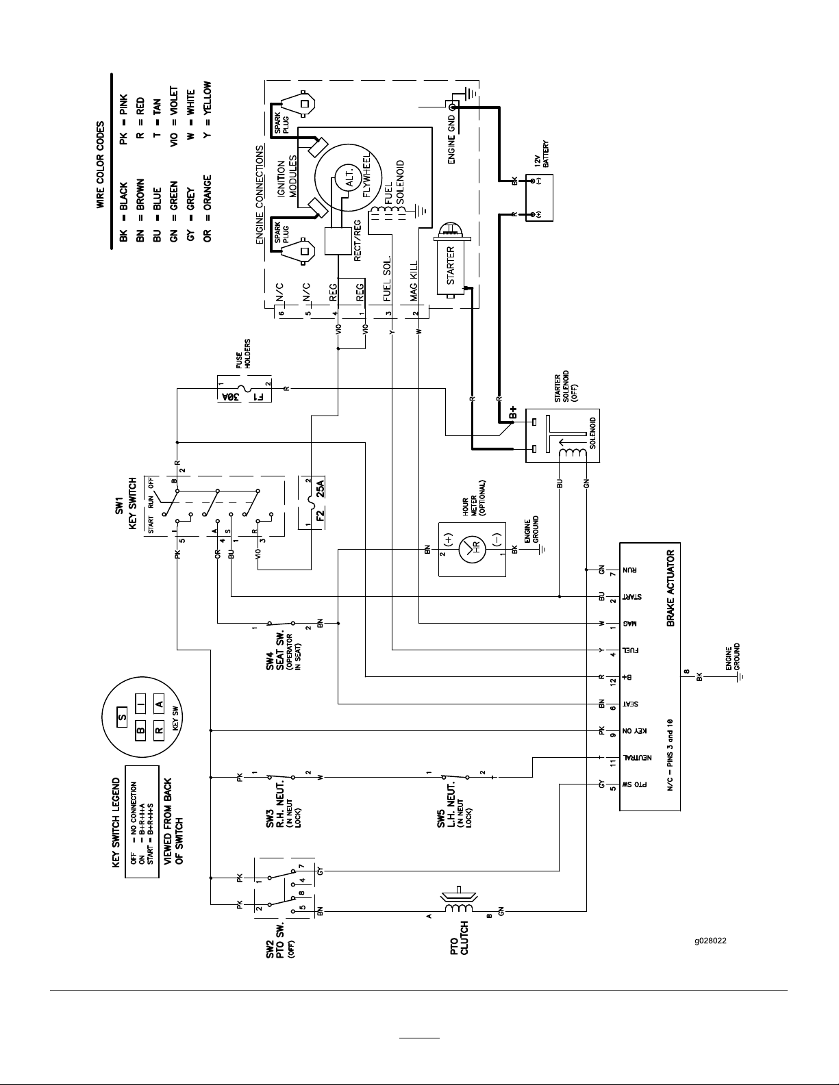
Schematics
ElectricalDiagram(Rev .A)
50
Page 51

InternationalDistributorList
Distributor:
AgrolancKft
AsianAmericanIndustrial(AAI)
B-RayCorporation
BrisaGoodsLLC
CascoSalesCompany
CeresS.A.CostaRica
CSSCTurfEquipment(pvt)Ltd.SriLanka
CyrilJohnston&Co.
CyrilJohnston&Co.RepublicofIreland
FatDragon
FemcoS.A.Guatemala
FIVEMANSNew-T echCo.,LtdChina
ForGarderOU
G.Y .K.CompanyLtd.
GeomechanikiofAthensGreece
GolfinternationalTurizm
HakoGroundandGardenSweden
HakoGroundandGarden
HayterLimited(U.K.)
HydroturfInt.CoDubai
HydroturfEgyptLLC
IrrimacPortugal351212388260ToroEuropeNVBelgium3214562960
IrrigationProductsInt'lPvtLtd.India00914424494387ValtechMorocco212537663636
JeanHeybroekb.v.Netherlands3130639461 1VictusEmakPoland48618238369
Country:
Hungary3627539640
HongKong85224977804
Korea82325512076
Mexico12104952417
PuertoRico7877888383
NorthernIreland442890813121
China
Estonia3723846060
Japan81726325861Riversa
Turkey902163365993
Norway4722907760
UnitedKingdom441279723444
UnitedArabEmirates97143479479T -MarktLogisticsLtd.Hungary3626525500
Egypt2025194308ToroAustraliaAustralia61395807355
PhoneNumber:Distributor:
MaquiverS.A.Colombia
MaruyamaMfg.Co.Inc.
Mountelda.s.CzechRepublic
Mountelda.s.Slovakia
5062391138
94112746100
442890813121ParklandProductsLtd.NewZealand6433493760
8861080841322
5024423277
86-10-63816136
30109350054
4635100000
MunditolS.A.
NormaGarden
OslingerTurfEquipmentSA
OyHakoGroundandGardenAb
Perfetto
PratoverdeSRL.
Prochaska&Cie
RTCohen2004Ltd.
LelyTurfcare
Lely(U.K.)Limited
SolvertS.A.S.
SpyprosStavrinidesLimitedCyprus
SurgeSystemsIndiaLimited
Country:
Japan81332522285
Argentina541 148219999
Russia749541 16120
Ecuador59342396970
Finland35898700733
Poland48618208416
Italy390499128128
Austria4312785100
Israel97298617979
Spain
Denmark4566109200
UnitedKingdom441480226800
France33130817700
India911292299901
PhoneNumber:
5712364079
420255704220
420255704220
34952837500
35722434131
EuropeanPrivacyNotice
TheInformationToroCollects
ToroWarrantyCompany(T oro)respectsyourprivacy.Inordertoprocessyourwarrantyclaimandcontactyouintheeventofaproductrecall,weaskyou
tosharecertainpersonalinformationwithus,eitherdirectlyorthroughyourlocalT orocompanyordealer.
TheT orowarrantysystemishostedonserverslocatedwithintheUnitedStateswhereprivacylawmaynotprovidethesameprotectionasapplies
inyourcountry.
BYSHARINGYOURPERSONALINFORMATIONWITHUS,YOUARECONSENTINGTOTHEPROCESSINGOFYOURPERSONALINFORMATION
ASDESCRIBEDINTHISPRIV ACYNOTICE.
TheWayT oroUsesInformation
Toromayuseyourpersonalinformationtoprocesswarrantyclaims,tocontactyouintheeventofaproductrecallandforanyotherpurposewhichwetell
youabout.ToromayshareyourinformationwithT oro'safliates,dealersorotherbusinesspartnersinconnectionwithanyoftheseactivities.Wewillnot
sellyourpersonalinformationtoanyothercompany.Wereservetherighttodisclosepersonalinformationinordertocomplywithapplicablelawsand
withrequestsbytheappropriateauthorities,tooperateoursystemsproperlyorforourownprotectionorthatofotherusers.
RetentionofyourPersonalInformation
Wewillkeepyourpersonalinformationaslongasweneeditforthepurposesforwhichitwasoriginallycollectedorforotherlegitimatepurposes
(suchasregulatorycompliance),orasrequiredbyapplicablelaw .
Toro'sCommitmenttoSecurityofYourPersonalInformation
Wetakereasonableprecautionsinordertoprotectthesecurityofyourpersonalinformation.Wealsotakestepstomaintaintheaccuracyandcurrent
statusofpersonalinformation.
AccessandCorrectionofyourPersonalInformation
Ifyouwouldliketorevieworcorrectyourpersonalinformation,pleasecontactusbyemailatlegal@toro.com.
AustralianConsumerLaw
AustraliancustomerswillnddetailsrelatingtotheAustralianConsumerLaweitherinsidetheboxoratyourlocalT oroDealer.
374-0269RevK
Page 52

LimitedWarranty(seewarrantyperiodsbelow)
TheToroWarranty
TimeCutter
and
TITAN
Mowers
ConditionsandProductsCovered
TheT oroCompanyanditsafliate,ToroWarrantyCompany,pursuanttoan
agreementbetweenthem,jointlypromisetorepairtheToroProductslisted
belowifdefectiveinmaterialsorworkmanship.
Thefollowingtimeperiodsapplyfromthedateofpurchasebytheoriginal
owner:
ProductsWarrantyPeriod
TimeCutterandMXMowers
•Engines
1
Residentialuse
—ResidentialuseKawasaki–3years
2
–3years
Kohler–3years
Toro–3years
TimeCutterandMXMowersCommercialuse30days
•Engines
1
—Commercialuse
Kawasaki–3years
Kohler–90days
Toro–90days
TITANSWandZSSeriesMowers–
ResidentialorCommercialuse
•Engines
1
—Residentialor
Commercialuse
•Frame
TITANMXSeriesMowers–
ResidentialorCommercialuse
•Engines
1
—Residentialor
Commercialuse
•Frame
3yearsor300hours
Kawasaki–3years
Lifetime(originalowneronly)
4yearsor400hours
Kawasaki–3years
Lifetime(originalowneronly)
3
4
3
4
AllMowers
•Attachments1year
•Battery90daysPartsandLabor
1yearPartsonly
•BeltsandTires90days
1
SomeenginesusedonT oroProductsarewarrantedbytheenginemanufacturer.
2
Residentialusemeansuseoftheproductonthesamelotasyourhome.Useatmorethanone
locationisconsideredcommercialuseandthecommercialusewarrantywouldapply .
3
Whicheveroccursrst.
4
LifetimeFrameW arranty-Ifthemainframe,consistingofthepartsweldedtogethertoformthe
tractorstructurethatothercomponentssuchastheenginearesecuredto,cracksorbreaksin
normaluse,itwillberepairedorreplaced,atT oro'soption,underwarrantyatnocostforpartsand
labor.Framefailureduetomisuseorabuseandfailureorrepairrequiredduetorustorcorrosion
arenotcovered.
Warrantymaybedeniedifthehourmeterisdisconnected,altered,or
showssignsofbeingtamperedwith.
OwnerResponsibilities
YoumustmaintainyourToroProductbyfollowingthemaintenance
proceduresdescribedintheOperator'sManual.Suchroutinemaintenance,
whetherperformedbyadealerorbyyou,isatyourexpense.
InstructionsforObtainingWarrantyService
IfyouthinkthatyourT oroProductcontainsadefectinmaterialsor
workmanship,followthisprocedure:
1.ContactanyAuthorizedT oroServiceDealertoarrangeserviceat
theirdealership.Tolocateadealerconvenienttoyou,accessourweb
siteatwww .Toro.com.Youmayalsocallthenumberslistedinitem#3
tousethe24-hourT oroDealerlocatorsystem.
2.Bringtheproductandyourproofofpurchase(salesreceipt)tothe
ServiceDealer.Thedealerwilldiagnosetheproblemanddetermineif
itiscoveredunderwarranty.
3.IfforanyreasonyouaredissatisedwiththeServiceDealer’s
analysisorwiththeassistanceprovided,contactusat:
ToroWarrantyCompany
CustomerCareDepartment,RLCDivision
811 1LyndaleAvenueSouth
Bloomington,MN55420-1196
Tollfreeat866-216-6029(U.S.customers)
Tollfreeat866-216-6030(Canadiancustomers)
ItemsandConditionsNotCovered
Thereisnootherexpresswarrantyexceptforspecialemissionsystem
coverageandenginewarrantycoverageonsomeproducts.Thisexpress
warrantydoesnotcoverthefollowing:
•Costofregularmaintenanceserviceorparts,suchaslters,fuel,
lubricants,oilchanges,sparkplugs,airltersbladesharpeningorworn
blades,cable/linkageadjustments,orbrakeandclutchadjustments
•Componentsfailingduetonormalwear
•Anyproductorpartwhichhasbeenalteredormisusedorneglected
orrequiresreplacementorrepairduetoaccidentsorlackofproper
maintenance
•Pickupanddeliverycharges
•RepairsorattemptedrepairsbyanyoneotherthananAuthorizedT oro
ServiceDealer
•Repairsnecessaryduetofailuretofollowrecommendedfuel
procedure(consultOperator'sManualformoredetails)
–Removingcontaminantsfromthefuelsystemisnotcovered
–Useofoldfuel(morethanonemonthold)orfuelwhichcontains
morethan10%ethanolormorethat15%MTBE
–Failuretodrainthefuelsystempriortoanyperiodofnon-use
overonemonth
GeneralConditions
AllrepairscoveredbythesewarrantiesmustbeperformedbyanAuthorized
ToroServiceDealerusingT oroapprovedreplacementparts.
NeitherTheToroCompanynorToroWarrantyCompanyisliablefor
indirect,incidentalorconsequentialdamagesinconnectionwiththe
useoftheToroProductscoveredbythiswarranty,includingany
costorexpenseofprovidingsubstituteequipmentorserviceduring
reasonableperiodsofmalfunctionornon-usependingcompletionof
repairsunderthiswarranty.
Allimpliedwarrantiesofmerchantability(thattheproductistfor
ordinaryuse)andtnessforuse(thattheproductistforaparticular
purpose)arelimitedtothedurationoftheexpresswarranty.
Somestatesdonotallowexclusionsofincidentalorconsequential
damages,orlimitationsonhowlonganimpliedwarrantylasts,sothe
aboveexclusionsandlimitationsmaynotapplytoyou.
Thiswarrantygivesyouspeciclegalrights,andyoumayalsohaveother
rightswhichvaryfromstatetostate.
CountriesOtherthantheUnitedStatesorCanada
ThiswarrantyisnotvalidinMexico.CustomerswhohavepurchasedT oroproductsoutsidetheUnitedStatesorCanadashouldcontacttheirToro
Distributor(Dealer)toobtainguaranteepoliciesforyourcountry,province,orstate.IfforanyreasonyouaredissatisedwithyourDistributor'sserviceor
havedifcultyobtainingguaranteeinformation,contacttheT oroimporter.Ifallotherremediesfail,youmaycontactusatT oroWarrantyCompany .
AustralianConsumerLaw:AustraliancustomerswillnddetailsrelatingtotheAustralianConsumerLaweitherinsidetheboxoratyourlocalT oro
Dealer.
374-0258RevF
 Loading...