

Page 1
FormNo.3409-383RevA
TimeCutter
®
ZS3200Sor4200S
RidingMower
ModelNo.74650—SerialNo.400000000andUp
ModelNo.74655—SerialNo.400000000andUp
Registeratwww.T oro.com.
OriginalInstructions(EN)
*3409-383*A
Page 2
ThisproductcomplieswithallrelevantEuropeandirectives;
fordetails,pleaseseetheseparateproductspecicDeclaration
ofConformity(DOC)sheet.
GrossHorsepower
Thegrossornethorsepowerofthisenginewaslaboratory
ratedbytheenginemanufacturerinaccordancewiththe
SocietyofAutomotiveEngineers(SAE)J1940.Ascongured
tomeetsafety,emission,andoperatingrequirements,
theactualenginetorqueonthisclassofmowerwillbe
signicantlylower.
Gotowww .Toro.comtoviewspecicationsonyourmower
model.
Important:IfyouareusingamachinewithaT oro
engineabove1500m(5,000ft)foracontinuousperiod,
ensurethattheHighAltitudeKithasbeeninstalledso
thattheenginemeetsCARB/EPAemissionregulations.
TheHighAltitudeKitincreasesengineperformance
whilepreventingspark-plugfouling,hardstarting,and
increasedemissions.Onceyouhaveinstalledthekit,
attachthehigh-altitudelabelnexttotheserialdecal
onthemachine.ContactanyAuthorizedToroService
DealertoobtaintheproperHighAltitudeKitand
high-altitudelabelforyourmachine.Tolocateadealer
convenienttoyou,accessourwebsiteatwww .Toro.com
orcontactourToroCustomerCareDepartmentatthe
number(s)listedinyourEmissionControlWarranty
Statement.
Removethekitfromtheengineandrestoretheengine
toitsoriginalfactorycongurationwhenrunningthe
engineunder1500m(5,000ft).Donotoperateanengine
thathasbeenconvertedforhigh-altitudeuseatlower
altitudes;otherwise,youcouldoverheatanddamage
theengine.
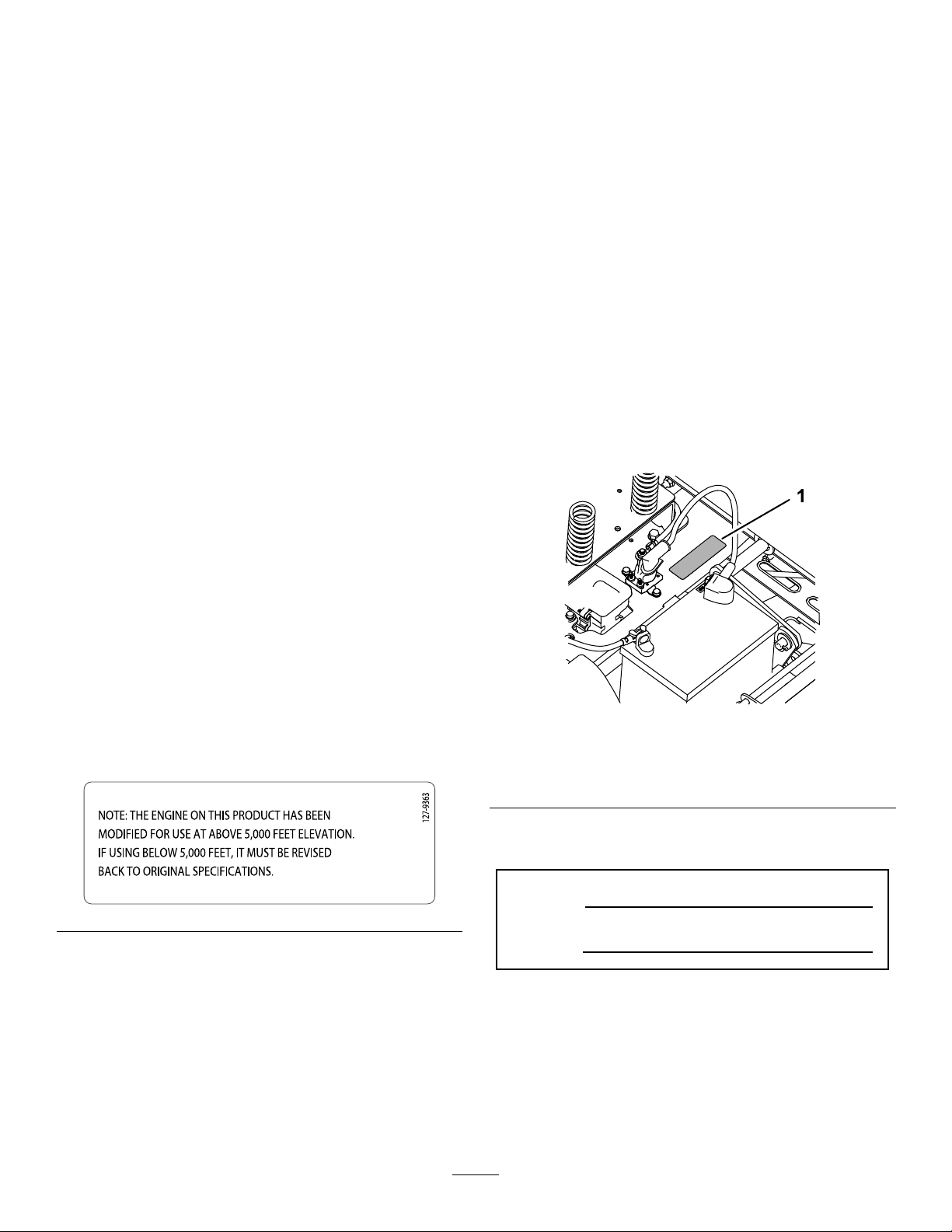
Ifyouareunsurewhetherornotyourmachinehasbeen
convertedforhigh-altitudeuse,lookforthefollowing
label.
Introduction
Thismachineisaride-on,rotary-bladeintendedtobeused
byhomeownersinresidentialapplications.Itisprimarily
designedforcuttinggrassonwell-maintainedlawns.Itisnot
designedforcuttingbrush,mowinggrassandothergrowth
alongsidehighways,orforagriculturaluses.
Readthisinformationcarefullytolearnhowtooperateand
maintainyourproductproperlyandtoavoidinjuryand
productdamage.Youareresponsibleforoperatingthe
productproperlyandsafely.
YoumaycontactTorodirectlyatwww .Toro.comforproduct
safetyandoperationtrainingmaterials,accessoryinformation,
helpndingadealer,ortoregisteryourproduct.
Wheneveryouneedservice,genuineT oroparts,oradditional
information,contactanAuthorizedServiceDealerorToro
CustomerServiceandhavethemodelandserialnumbersof
yourproductready.Figure1identiesthelocationofthe
modelandserialnumbersontheproduct.Writethenumbers
inthespaceprovided.
g188142
Figure1
Undertheseat
1.Modelandserial-numberplate
©2016—TheToro®Company
8111LyndaleAvenueSouth
Bloomington,MN55420
Writetheproductmodelandserialnumbersinthespace
below:
decal127-9363
ModelNo.
SerialNo.
Thismanualidentiespotentialhazardsandhassafety
messagesidentiedbythesafety-alertsymbol(Figure2),
whichsignalsahazardthatmaycauseseriousinjuryordeath
ifyoudonotfollowtherecommendedprecautions.
Contactusatwww.Toro.com.
2
PrintedintheUSA
AllRightsReserved
Page 3

Contents
Figure2
1.Safety-alertsymbol
Thismanualuses2wordstohighlightinformation.
Importantcallsattentiontospecialmechanicalinformation
andNoteemphasizesgeneralinformationworthyofspecial
attention.
g000502
Safety...........................................................................4
GeneralSafety.........................................................4
SlopeIndicator.......................................................5
SafetyandInstructionalDecals.................................6
ProductOverview.........................................................10
Controls...............................................................10
BeforeOperation......................................................11
BeforeOperationSafety..........................................11
RecommendedFuel................................................12
UsingStabilizer/Conditioner...................................12
FillingtheFuelTank...............................................12
CheckingtheEngine-OilLevel.................................13
BreakinginaNewMachine......................................13
ThinkSafetyFirst...................................................13
UsingtheSafety-InterlockSystem.............................14
PositioningtheSeat................................................14
AdjustingtheMotion-ControlLevers........................14
ConvertingtoSideDischarge...................................15
DuringOperation.....................................................17
DuringOperationSafety.........................................17
OperatingtheMowerBlade-ControlSwitch
(PTO)...............................................................18
OperatingtheThrottle............................................18
OperatingtheIgnitionSwitch..................................19
StartingandShuttingOfftheEngine.........................19
UsingtheMotion-ControlLevers.............................20
DrivingtheMachine...............................................20
StoppingtheMachine.............................................22
AdjustingtheHeightofCut.....................................22
AdjustingtheAnti-ScalpRollers...............................22
UsingtheSideDischarge.........................................23
OperatingTips......................................................23
AfterOperation........................................................24
AfterOperationSafety............................................24
PushingtheMachinebyHand..................................24
TransportingtheMachine........................................25
LoadingtheMachine..............................................25
Maintenance.................................................................27
RecommendedMaintenanceSchedule(s)......................27
Pre-MaintenanceProcedures......................................28
MaintenanceandStorage.........................................28
RaisingtheSeat......................................................28
ReleasingtheMower-DeckCurtain...........................28
Lubrication...............................................................29
GreasingtheBearings.............................................29
EngineMaintenance..................................................29
EngineSafety.........................................................29
ServicingtheAirCleaner.........................................29
ServicingtheEngineOil..........................................30
ServicingtheSparkPlug..........................................33
CleaningtheBlowerHousing...................................34
FuelSystemMaintenance...........................................34
ReplacingtheIn-LineFuelFilter...............................34
ElectricalSystemMaintenance....................................35
ElectricalSystemSafety...........................................35
ServicingtheBattery...............................................35
3
Page 4

ServicingtheFuses.................................................37
DriveSystemMaintenance.........................................37
CheckingtheTirePressure......................................37
ReleasingtheElectricBrake.....................................38
MowerMaintenance...................................................38
ServicingtheCuttingBlades.....................................38
LevelingtheMowerDeck........................................41
RemovingtheMowerDeck.....................................43
InstallingtheMowerDeck.......................................43
ReplacingtheGrassDeector..................................44
MowerBeltMaintenance............................................45
InspectingtheBelts................................................45
ReplacingtheMowerBelt........................................45
Cleaning...................................................................46
WashingtheUndersideoftheMower........................46
Storage........................................................................47
CleaningandStorage..............................................47
Troubleshooting...........................................................49
Schematics...................................................................51
Safety
ThismachinehasbeendesignedinaccordancewithENISO
5395:2013.
GeneralSafety
Thisproductiscapableofamputatinghandsandfeetand
ofthrowingobjects.Alwaysfollowallsafetyinstructionsto
avoidseriouspersonalinjury.
Usingthisproductforpurposesotherthanitsintendeduse
couldprovedangeroustoyouandbystanders.
•ReadandunderstandthecontentsofthisOperator’ sManual
beforeyoustarttheengine.Ensurethateveryoneusing
thisproductknowshowtouseitandunderstandsthe
warnings.
•Donotputyourhandsorfeetnearmovingcomponents
ofthemachine.
•Donotoperatethemachinewithoutallguardsandother
safetyprotectivedevicesinplaceandworkingonthe
machine.
•Keepclearofanydischargeopening.Keepbystandersa
safedistanceawayfromthemachine.
•Keepchildrenoutoftheoperatingarea.Neverallow
childrentooperatethemachine.
•Stopthemachineandshutofftheenginebeforeservicing,
fueling,oruncloggingthemachine.
Improperlyusingormaintainingthismachinecanresult
ininjury.Toreducethepotentialforinjury,complywith
thesesafetyinstructionsandalwayspayattentiontothe
safety-alertsymbol,whichmeansCaution,Warning,or
Danger—personalsafetyinstruction.Failuretocomplywith
theseinstructionsmayresultinpersonalinjuryordeath.
Youcanndadditionalitemsofsafetyinformationintheir
respectivesectionsthroughoutthismanual.
4
Page 5
SlopeIndicator
G011841
Figure4
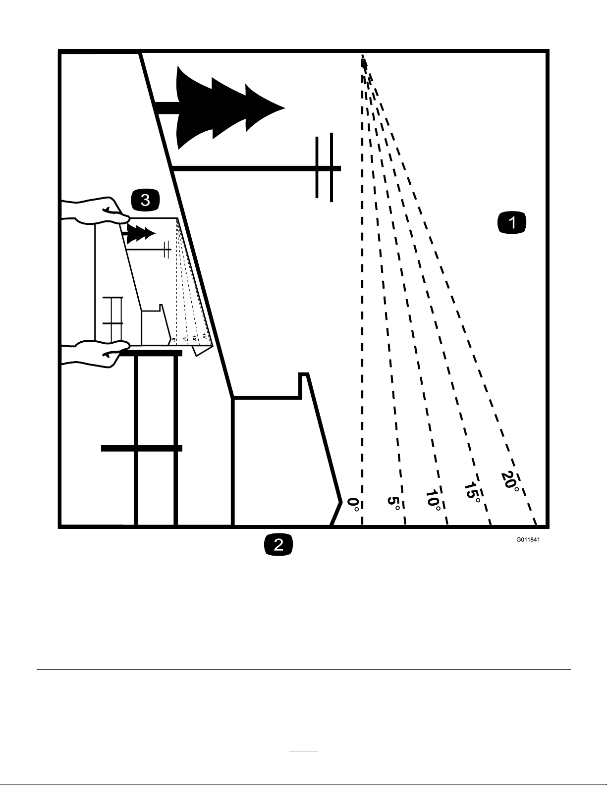
Thispagemaybecopiedforpersonaluse.
1.Themaximumslopeyoucansafelyoperatethemachineonis15degrees.Usetheslopecharttodeterminethedegreeofslope
ofhillsbeforeoperating.Donotoperatethismachineonaslopegreaterthan15degrees.Foldalongtheappropriateline
tomatchtherecommendedslope.
2.Alignthisedgewithaverticalsurface,atree,building,fencepole,etc.
3.Exampleofhowtocompareslopewithfoldededge
5
g011841
Page 6
SafetyandInstructionalDecals
Safetydecalsandinstructionsareeasilyvisibletotheoperatorandarelocatednearanyareaofpotential
danger.Replaceanydecalthatisdamagedormissing.
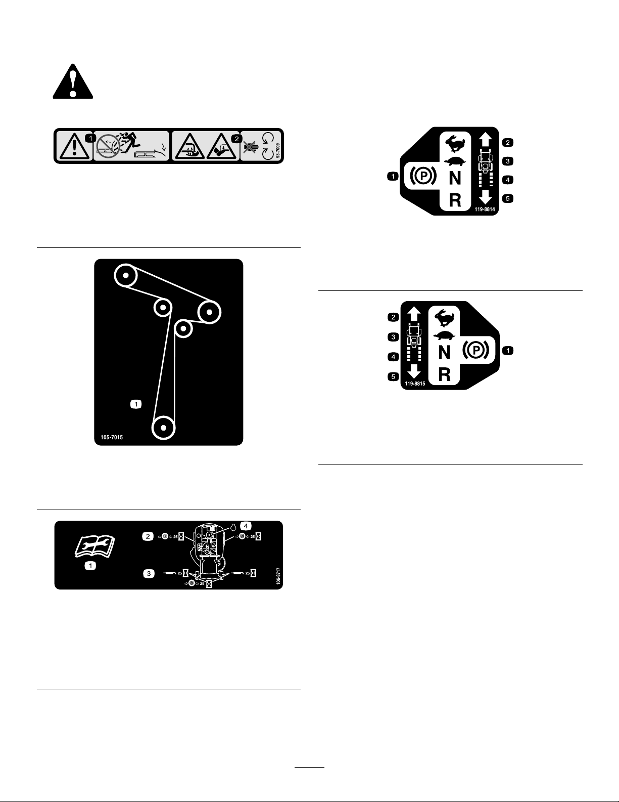
93-7009
1.Warning—donotoperatethemowerwiththedeectorup
orremoved;keepthedeectorinplace.
2.Cutting/dismembermenthazardofhandorfoot,mower
blade—stayawayfrommovingparts.
decal93-7009
decal119-8814
119-8814
1.PARKINGposition4.NEUTRAL
2.FAST5.REVERSE
3.SLOW
105-7015
ForModelswith107cm(42-inch)Decks
1.Beltrouting
106-8717
1.Readtheinstructionsbeforeservicingorperforming
maintenance.
2.Checktirepressureevery25operatinghours.
3.Greaseevery25operatinghours.
4.Engine
decal119-8815
119-8815
1.PARKINGposition4.NEUTRAL
2.FAST5.REVERSE
decal105-7015
decal106-8717
3.SLOW
6
Page 7
131-3948
decal131-3948
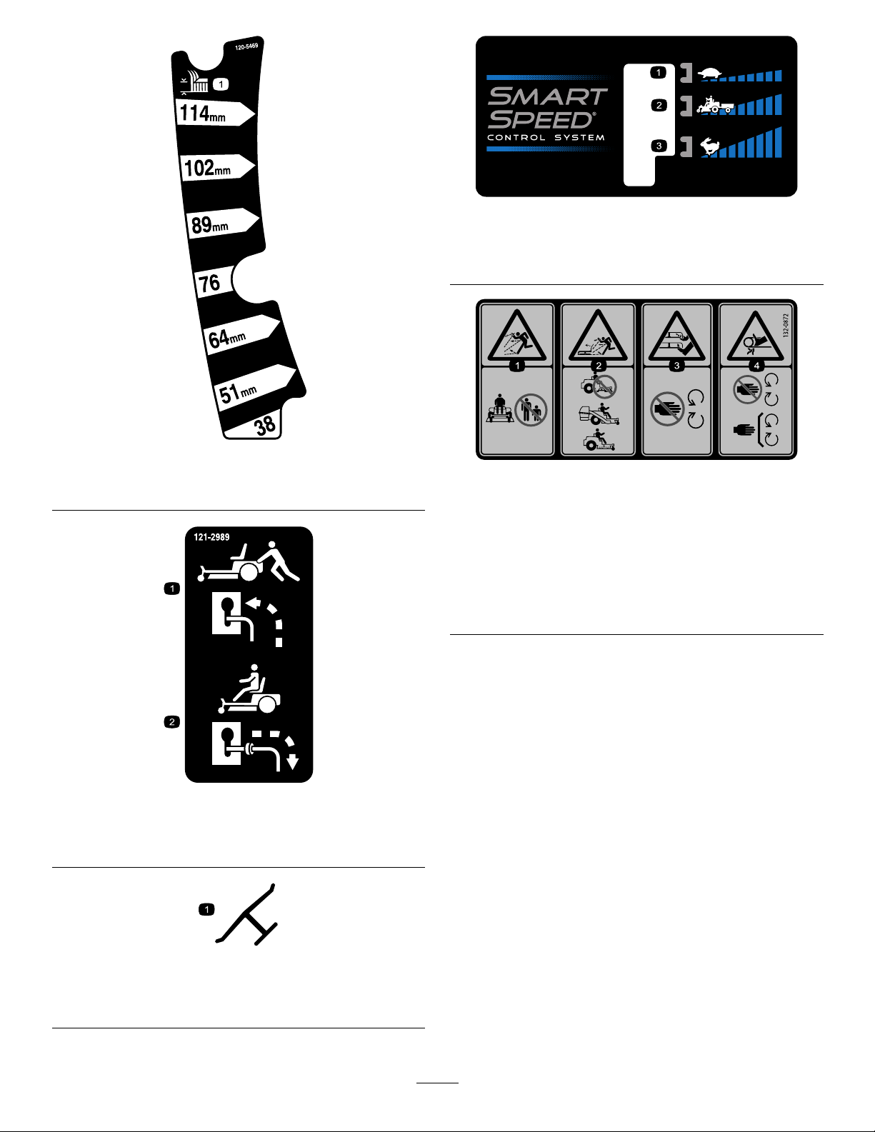
131-3948
1.Heightofcut
1.Slow
3.Fast
2.Towing
decal120-5469
120-5469
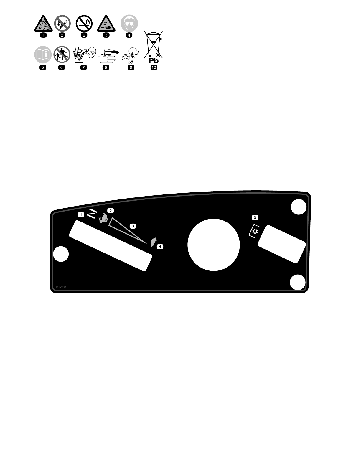
decal132-0872
132-0872
1.Thrownobject
hazard—keepbystanders
awayfromthemachine.
2.Thrownobjecthazard,
raisedbafe—donot
operatethemachinewith
anopendeck;usea
baggerorabafe.
3.Severinghazardofhand
orfoot—keepawayfrom
movingparts.
4.Entanglement
hazard—keepaway
frommovingparts;keep
allguardsandshieldsin
place.
121-2989
1.Bypassleverpositionfor
pushingthemachine
2.Bypassleverpositionfor
operatingthemachine
Manufacturer'sMark
1.Indicatesthebladeisidentiedasapartfromtheoriginal
machinemanufacturer.
decal121-2989b
decaloemmarkt
7
Page 8
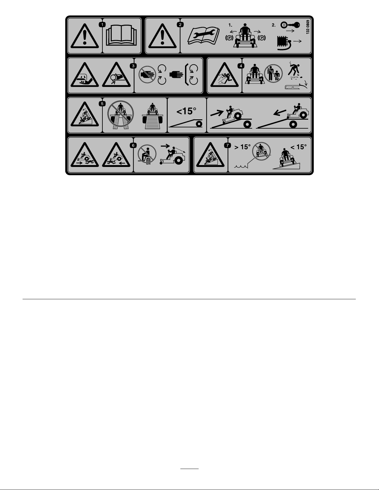
BatterySymbols
Someorallofthesesymbolsareonyourbattery
decalbatterysymbols
1.Explosionhazard
2.Nore,opename,or
6.Keepbystandersasafe
7.Weareyeprotection;
smoking.
3.Causticliquid/chemical
8.Batteryacidcancause
burnhazard
4.Weareyeprotection9.Flusheyesimmediately
5.ReadtheOperator's
10.Containslead;donot
Manual.
distancefromthebattery.
explosivegasescan
causeblindnessandother
injuries
blindnessorsevereburns.
withwaterandgetmedical
helpfast.
discard.
121-0771
1.Choke4.SLOW
2.FAST
3.Continuous-variablesetting
8
decal121-0771
5.Powertake-off(PTO)—Blade-controlswitch
Page 9
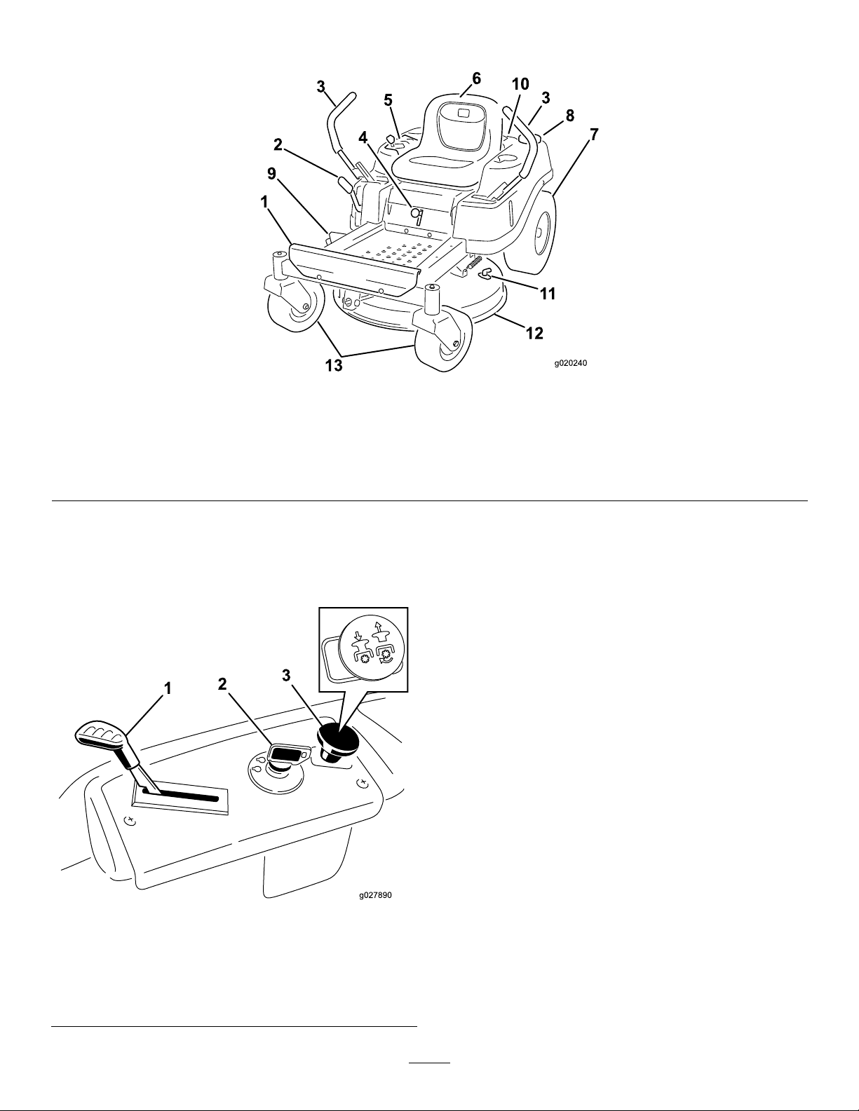
decal132-0869
132-0869
1.Warning—readthe
Operator'sManual.
2.Warning—beforeservicing,
engagetheparkingbrake,
removethekeyandthe
sparkplugconnection.
3.Cuttinghazardofhand,
mowerblade;pinching
hazardofhand,belt—keep
handsandfeetawayfrom
movingparts;keepall
guardsandshieldsinplace.
4.Thrownobject
hazard—keepbystanders
awayfromthemachine;
removedebrisfromthe
areabeforemowing;keep
thedeectorshielddown.
5.Ramptipping
hazard—whenloading
ontoatrailer,donotuse
dualramps;onlyusea
singlerampwideenough
forthemachineandthat
hasaninclinelessthan
15degrees;backupthe
ramp(inreverse)anddrive
forwardofftheramp.
6.Bodilyharmhazard—no
riders;lookbehindyou
whenmowinginreverse.
7.Tippinghazardon
slopes—donotuseon
slopesnearopenwater;do
notuseonslopesgreater
than15degrees.
9
Page 10
ProductOverview
g020240
1
2
3
4
5
6
7
8
10
11
12
13
9
3
g020240
Figure5
1.Footrest
2.Height-of-cutlever6.Operatorseat
3.Motion-controllever7.Reardrivewheel
4.Smart-speedlever
5.Controlpanel9.Deector
8.Fuel-tankcap12.Mowerdeck
Controls
BecomefamiliarwithallcontrolsinFigure5andFigure6
beforeyoustarttheengineandoperatethemachine.
10.Engine
11.Washouttting
IgnitionSwitch
Usethisswitchtostartthemowerengine.Ithas3positions:
START,RUN,andOFF.
13.Frontcasterwheels
Throttle/ChokeControl
Thethrottleandchokecontrolsarecombinedinto1control
lever.Thethrottlecontrolstheenginespeedandhasa
continuous-variablesettingfromSLOWtoFAST.Engagethe
chokebymovingtheleverpasttheFASTsettinguntilitstops
(Figure6).
Blade-ControlSwitch(PowerTakeoff)
Theblade-controlswitch,representedbyapower-takeoff
g027890
1.Throttle/Choke
2.Ignitionswitch
Figure6
ControlPanel
3.Blade-controlswitch
(powertakeoff)
(PTO)symbol,engagesanddisengagespowertothemower
blades(Figure6).
Motion-ControlLevers
Usethemotion-controlleverstodrivethemachineforward,
reverse,andturneitherdirection.
ParkPosition
Movethemotion-controlleversoutwardfromthecenterto
thePARKpositionwhenexitingthemachine(Figure22).
Alwayspositionthemotion-controlleversintothePARK
positionwhenyoustopthemachineorleaveitunattended.
10
Page 11
SmartSpeed™ControlSystemLever
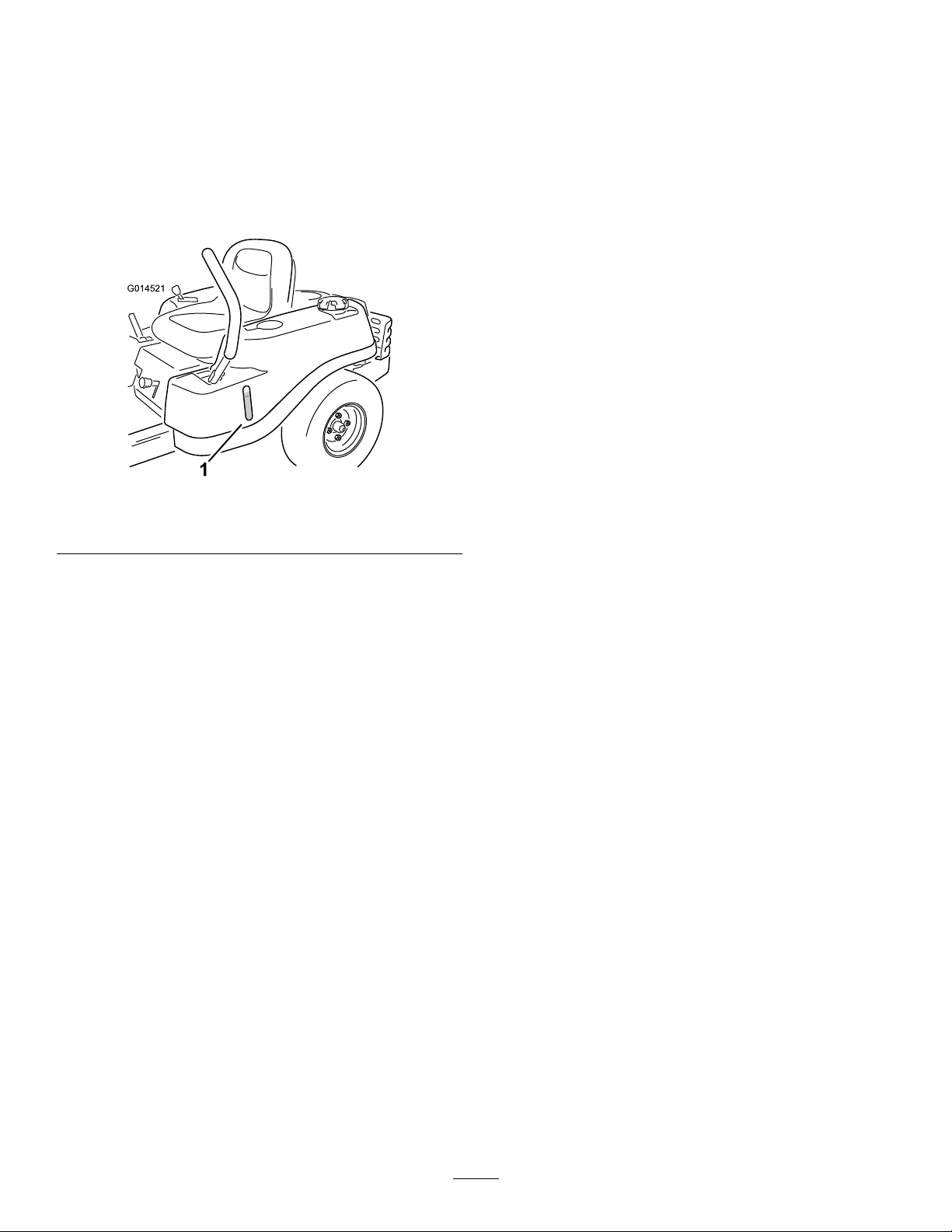
G014521
1
TheSmartSpeed™Control-Systemlever,locatedbelowthe
operatingposition,givesyouachoicetodrivethemachineat
3speedranges—trim,tow ,andmow(Figure5).
Operation
BeforeOperation
Fuel-PresenceWindow
Youcanusethefuelwindow ,locatedontheleftsideofthe
machine,toverifythepresenceoffuelinthetank(Figure7).
Figure7
1.Fuel-presencewindow
Height-of-CutLever
Usetheheight-of-cutlevertolowerandraisethedeckfrom
theseatedposition.Movingtheleverup(towardyou)raises
thedeckfromthegroundandmovingtheleverdown(away
fromyou)lowersthedecktowardtheground.Adjustthe
height-of-cutonlywhilethemachineisnotmoving(Figure5).
Attachments/Accessories
AselectionofToroapprovedattachmentsandaccessoriesis
availableforusewiththemachinetoenhanceandexpand
itscapabilities.ContactyourAuthorizedServiceDealeror
Distributororgotowww .Toro.comforalistofallapproved
attachmentsandaccessories.
BeforeOperationSafety
GeneralSafety
•Neverallowchildrenoruntrainedpeopletooperateor
servicethemachine.Localregulationsmayrestrictthe
ageoftheoperator.Theownerisresponsiblefortraining
alloperatorsandmechanics.
•Becomefamiliarwiththesafeoperationoftheequipment,
operatorcontrols,andsafetysigns.
•Knowhowtostopthemachineandshutofftheengine
quickly.
•Checkthatoperator-presencecontrols,safetyswitches,
andshieldsareattachedandfunctioningproperly.Donot
operatethemachineunlesstheyarefunctioningproperly.
g014521
•Beforemowing,alwaysinspectthemachinetoensurethat
theblades,bladebolts,andcuttingassembliesareingood
workingcondition.Replacewornordamagedbladesand
boltsinsetstopreservebalance.
•Inspecttheareawhereyouwillusethemachineand
removeallobjectsthatthemachinecouldthrow.
•Evaluatetheterraintodeterminetheappropriate
equipmentandanyattachmentsoraccessoriesrequiredto
operatethemachineproperlyandsafely.
FuelSafety
•Toavoidpersonalinjuryorpropertydamage,useextreme
careinhandlingfuel.Fuelvaporsareammableand
explosive.
•Extinguishallcigarettes,cigars,pipes,andothersources
ofignition.
•Useonlyanapprovedfuelcontainer.
•Donotremovethefuelcaporaddfueltothefueltank
whiletheengineisrunningorwhilehot.
•Donotrefuelthemachineindoors.
•Donotstorethemachineorfuelcontainerwherethere
isanopename,spark,orpilotlight,suchasonawater
heateroronotherappliances.
•Donotllcontainersinsideavehicleoronatruckor
trailerbedwithaplasticliner.Alwaysplacecontainerson
theground,awayfromyourvehiclebeforelling.
•Removetheequipmentfromthetruckortrailerand
refuelitwhileitisontheground.Ifthisisnotpossible,
thenrefuelfromaportablecontainerratherthana
fuel-dispensernozzle.
•Donotoperatethemachinewithouttheentireexhaust
systeminplaceandinproperworkingcondition.
11
Page 12
•Keepthefuel-dispensernozzleincontactwiththerimof
g027243
A
B
E
D
C
thefueltankorcontaineropeningatalltimesuntilfueling
iscomplete.Donotuseanozzlelock-opendevice.
•Ifyouspillfuelonyourclothing,changeyourclothing
immediately.Wipeupanyfuelthatspills.
•Neveroverllthefueltank.Replacethefuelcapand
tightenitsecurely.
•Storefuelinanapprovedcontainerandkeepitoutofthe
reachofchildren.Neverbuymorethana30-daysupply
offuel.
•Donotllthefueltankcompletelyfull.Addfueltothe
fueltankuntilthelevelis6to13mm(1/4to1/2inch)
belowthebottomofthellerneck.Thisemptyspacein
thetankallowsfueltoexpand.
–Avoidprolongedbreathingofvapors.
–Keepyourfaceawayfromthenozzleandfueltank
opening.
–Avoidcontactwithskin;washoffspillswithsoapand
water.
UsingStabilizer/Conditioner
Useafuelstabilizer/conditionerinthemachinetoprovide
thefollowingbenets:
•Keepsfuelfreshduringstorageof90daysorless(drain
thefueltankwhenstoringthemachineformorethan
90days)
•Cleanstheenginewhileitruns
•Eliminatesgum-likevarnishbuildupinthefuelsystem,
whichcauseshardstarting
Important:Donotusefueladditivescontaining
methanolorethanol.
Addthecorrectamountoffuelstabilizer/conditioner
tothefuel.
Note:Afuelstabilizer/conditionerismosteffective
whenmixedwithfreshfuel.T ominimizethechanceof
varnishdepositsinthefuelsystem,usefuelstabilizerat
alltimes.
FillingtheFuelTank
RecommendedFuel
•Forbestresults,useonlyclean,fresh(lessthan30days
old),unleadedgasolinewithanoctaneratingof87or
higher((R+M)/2ratingmethod).
•Ethanol:Gasolinewithupto10%ethanol(gasohol)
or15%MTBE(methyltertiarybutylether)byvolume
isacceptable.EthanolandMTBEarenotthesame.
Gasolinewith15%ethanol(E15)byvolumeisnot
approvedforuse.Neverusegasolinethatcontains
morethan10%ethanolbyvolume,suchasE15
(contains15%ethanol),E20(contains20%ethanol),or
E85(containsupto85%ethanol).Usingunapproved
gasolinemaycauseperformanceproblemsand/orengine
damagewhichmaynotbecoveredunderwarranty.
•Donotusegasolinecontainingmethanol.
•Donotstorefueleitherinthefueltankorfuelcontainers
•Donotaddoiltogasoline.
overthewinterunlessyouuseafuelstabilizer.
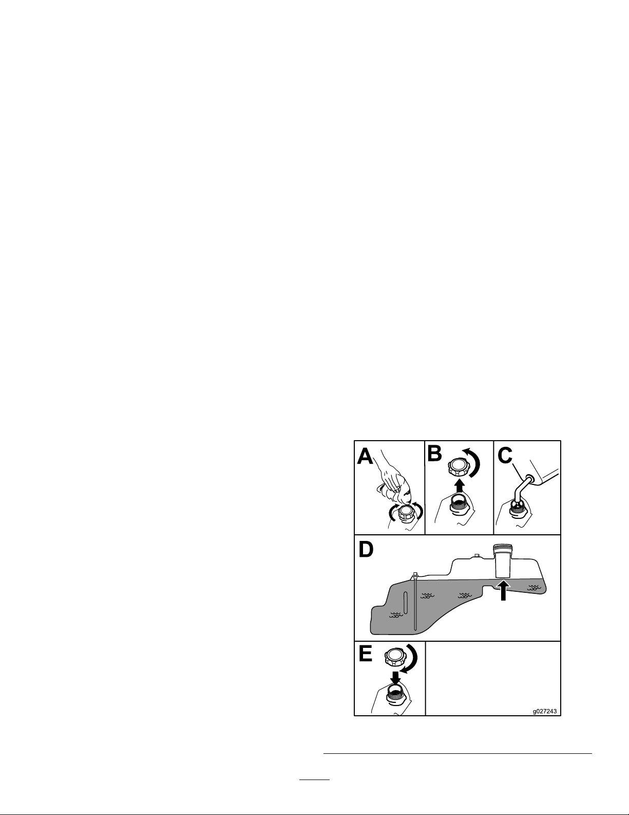
1.Parkthemachineonlevelground.
2.Shutofftheengineandengagetheparkingbrake.
3.Cleanaroundthefuel-tankcap.
4.Fillthefueltanktothebottomofthellerneck(Figure
8).
Note:Donotllthefueltankcompletelyfull.The
emptyspaceinthetankallowsthefueltoexpand.
g027243
Figure8
12
Page 13
CheckingtheEngine-OilLevel
G009027
1
2
Beforeyoustarttheengineandusethemachine,check
theoillevelintheenginecrankcase;refertoCheckingthe
Engine-OilLevel(page13).
BreakinginaNewMachine
Newenginestaketimetodevelopfullpower.Mowerdecks
anddrivesystemshavehigherfrictionwhennew,placing
additionalloadontheengine.Allow40to50hoursof
break-intimefornewmachinestodevelopfullpowerand
bestperformance.
ThinkSafetyFirst
Pleasereadallsafetyinstructionsandsymbolsinthesafety
section.Knowingthisinformationcouldhelpyouor
bystandersavoidinjury.
DANGER
Operatingthemachineonwetgrassorsteepslopes
cancauseslidingandlossofcontrol.
•Donotoperateonslopesgreaterthan15degrees.
•Reducespeedanduseextremecautionon
slopes.
•Donotoperatethemachinenearwater.
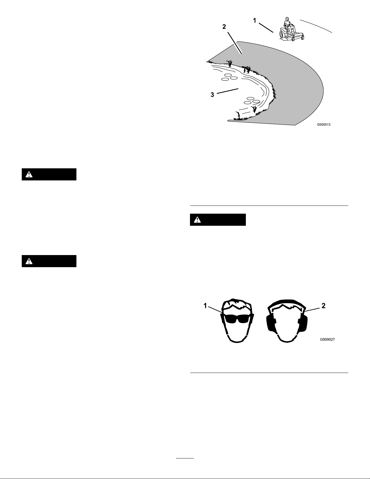
DANGER
Wheelsdroppingoveredgescancauserollovers,
whichmayresultinseriousinjury,death,or
drowning.
Donotoperatethemachineneardrop-offs.
Figure9
1.SafeZone—usethe
machinehereonslopes
lessthan15degreesor
atareas.
2.DangerZone—usea
walk-behindmowerand/or
ahandtrimmeronslopes
greaterthan15degrees,
neardrop-offsandwater.
3.Water
CAUTION
Thismachineproducessoundlevelsinexcessof
85dBAattheoperator’searandcancausehearing
lossthroughextendedperiodsofexposure.
Wearhearingprotectionwhenoperatingthis
machine.
Useprotectiveequipmentforyoureyes,ears,hands,feet,
andhead.
g000513
g009027
Figure10
1.Weareyeprotection.2.Wearhearingprotection.
13
Page 14
UsingtheSafety-Interlock
g027249
B
C
A
g027252
B
A
System
WARNING
Ifthesafety-interlockswitchesaredisconnectedor
damaged,themachinecouldoperateunexpectedly,
causingpersonalinjury.
•Donottamperwiththeinterlockswitches.
•Checktheoperationoftheinterlockswitches
dailyandreplaceanydamagedswitchesbefore
operatingthemachine.
UnderstandingtheSafety-Interlock
System
Thesafety-interlocksystemisdesignedtopreventtheengine
fromstartingunless:
•Theblade-controlswitch(PTO)isdisengaged.
PositioningtheSeat
•Themotion-controlleversareinthePARKposition.
Thesafety-interlocksystemalsoisdesignedtoshutoffthe
enginewheneverthecontrolleversareoutofthePARK
positionandyourisefromtheseat.
TestingtheSafety-InterlockSystem
Testthesafety-interlocksystembeforeyouusethemachine
eachtime.Ifthesafetysystemdoesnotoperateasdescribed
below,haveanAuthorizedServiceDealerrepairthesafety
systemimmediately.
1.Sitontheseat,movethemotion-controlleversinthe
PARKposition,andmovetheblade-controlswitchto
theONposition.Trystartingtheengine;theengine
shouldnotcrank.
2.Sitontheseatandmovetheblade-controlswitchto
theOFFposition.Moveeithermotion-controlleverto
thecenter,unlockedposition.Trystartingtheengine;
theengineshouldnotcrank.Repeatwiththeother
motion-controllever.
3.Sitontheseat,movetheblade-controlswitchtothe
OFFposition,andlockthemotion-controlleversin
thePARKposition.Starttheengine.Whiletheengine
isrunning,engagetheblade-controlswitch,andrise
slightlyfromtheseat;theengineshouldshutoff.
4.Sitontheseat,movetheblade-controlswitchtothe
OFFposition,andlockthemotion-controlleversinthe
PARKposition.Starttheengine.Whiletheengineis
running,movethemotion-controlleverstothecenter,
unlockedposition,engagetheblade-controlswitch,and
riseslightlyfromtheseat;theengineshouldshutoff.
g027249
Figure11
AdjustingtheMotion-Control Levers
AdjustingtheHeight
Youcanadjustthemotion-controllevershigherorlowerfor
maximumcomfort(Figure12).
g027252
Figure12
14
Page 15
AdjustingtheTilt
Youcanadjustthemotion-controlleversforwardorrearward
foryourcomfort.
1.Loosentheupperboltholdingthecontrollevertothe
control-armshaft.
2.Loosenthelowerboltjustenoughtopivotthecontrol
leverforwardorrearward(Figure12).
3.Tightenbothboltstosecurethecontrolleverinthe
newposition.
4.Repeattheadjustmentfortheothercontrollever.
ConvertingtoSideDischarge
ConvertingtoSideDischarge
ForModelswith81cm(32-inch)Mower
Decks
Thismowerdeckhastheoptiontooperateinthe
side-dischargemode.Removethedischargecoverfor
operatingintheside-dischargemode.
RemovingtheDischargeCoverforSideDischarge
1.Parkthemachineonalevelsurfaceanddisengagethe
blade-controlswitch.
2.Movethemotion-controlleversoutwardtoPARK
position,shutofftheengine,removethekey,and
waitforallmovingpartstostopbeforeleavingthe
operatingposition.
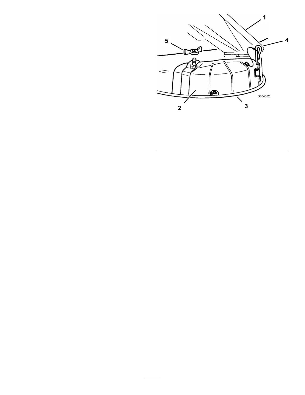
3.Removethewingnutandboltsecuringthecoverin
place(Figure13).
Note:Retainallofthepartsforfutureuse.
Figure13
1.Grassdeector
2.Dischargecover5.Wingnut
3.Lowerlip
4.Removethehingepinsecuringthecovertothedeck
(Figure13).
5.Liftthecoveroutandawayfromthedeck.
6.Lowerthegrassdeectoroverthedischargeopening.
Important:Ensurethatthemowerhasahinged
grassdeectorthatdispersesclippingstotheside
anddowntowardtheturf,whileinsidedischarge
mode.
InstallingtheDischargeCoverforMulching
1.Parkthemachineonalevelsurfaceanddisengagethe
blade-controlswitch.
2.Movethemotion-controlleversoutwardtoPARK
position,shutofftheengine,removethekey,and
waitforallmovingpartstostopbeforeleavingthe
operatingposition.
4.Hingepin
g004582
3.Liftthegrassdeectorandplacethedischargecover
overtheopeningontothelowerlipofthemowerand
slideitintothefronthinge(Figure13).
4.Slidethehingepinthroughthehinge(Figure13).
5.Securethedischargecovertothemowerwiththewing
nut(Figure13).
6.Lowerthegrassdeectoroverthedischargeopening.
15
Page 16

Machineswith107cm(42-inch)Mower
G009660
1
2
3
4
5
G005667
1
2
3
DecksOnly
Themowerdeckandmowerbladesshippedwiththismachine
weredesignedforoptimummulchingandsidedischarge
performance.
RemovingtheDischargeCoverforSide-Discharging
1.Parkthemachineonalevelsurfaceanddisengagethe
blade-controlswitch.
2.Movethemotion-controlleversoutwardtoPARK
position,shutofftheengine,removethekey,and
waitforallmovingpartstostopbeforeleavingthe
operatingposition.
3.Removethe2boltsandnutsthatsecurethedischarge
covertothemower(Figure14).
Figure15
1.Pivotrod
2.Cutoffbafe(originally
shippedwiththemachine)
3.Existingthinnut(3/8inch)
8.Torquethefastenerto7to9N∙m(14to18ft-lb).
9.Lowerthegrassdeectoroverthedischargeopening
Important:Ensurethatthemowerhasahinged
grassdeectorthatdispersesclippingstotheside
anddowntowardtheturf,whileinside-discharge
mode.
g005667
Figure14
1.Capnut(1/4inch)
2.Dischargecover5.Removethecover
3.Bolt(1/4x2-1/2inches)
4.Rotatethecoverup
4.Removethedischargecover.
5.Liftupthegrassdeector,andlocatethelocknuton
thedeectorpivotrod.
6.Removetheexistingthinnut(3/8inch).
7.Installthecutoffbafetotheexposedpivotrod
(Figure15).
Note:Usetheexistingthinnut(3/8inch)tosecure
thebafetothemower.
InstallingtheDischargeCoverforMulching
1.Parkthemachineonalevelsurfaceanddisengagethe
blade-controlswitch.
2.Movethemotion-controlleversoutwardtoPARK
position,shutofftheengine,removethekey,and
waitforallmovingpartstostopbeforeleavingthe
g009660
operatingposition.
3.Removethecutoffbafefromthemowerdeck(Figure
15).
4.Liftthegrassdeectorandslidethetabsontopofthe
dischargecoverunderthegrassdeectorretainingrod.
5.Rotatethedischargecoverdownovertheopening,and
ontothelowerlipofthemower(Figure16).
Note:Thecutoffbafewasshippedwiththemachine
asaloosepart.
16
Page 17
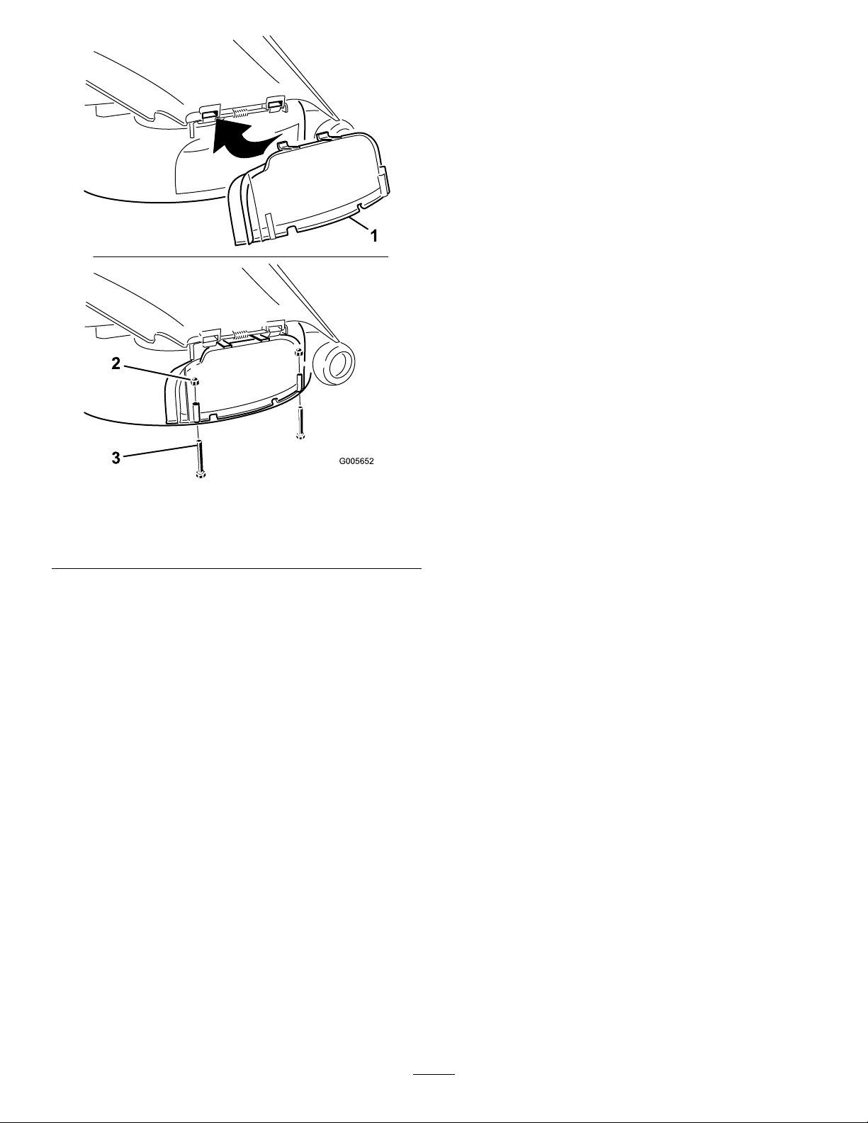
Figure16
1.Dischargecover
2.Capnut(1/4inch)
6.Securethedischargecovertothelowerlipofthe
mowerwith2bolts(1/4x2-1/2inches)and2capnuts
(1/4inch)asshowninFigure16.
Note:Donotovertightenthenuts;thiscoulddistort
thecoverandcausebladecontact.
3.Bolt(1/4x2-1/2inches)
DuringOperation
DuringOperationSafety
GeneralSafety
•Theowner/operatorcanpreventandisresponsiblefor
accidentsthatmaycausepersonalinjuryorproperty
damage.
•Wearappropriateclothing,includingeyeprotection;
slip-resistant,substantialfootwear;andhearing
protection.Tiebacklonghairanddonotwearjewelry.
•Donotoperatethemachinewhileill,tired,orunderthe
inuenceofalcoholordrugs.
•Nevercarrypassengersonthemachineandkeep
bystandersandpetsawayfromthemachineduring
operation.
•Operatethemachineonlyingoodvisibilitytoavoidholes
orhiddenhazards.
•Avoidmowingonwetgrass.Reducedtractioncould
causethemachinetoslide.
•Ensurethatalldrivesareinneutral,theparkingbrake
isengaged,andyouareintheoperatingpositionbefore
g005652
youstarttheengine.
•Keepyourhandsandfeetawayfromthecuttingunits.
Keepclearofthedischargeopeningatalltimes.
•Lookbehindanddownbeforebackinguptobesureof
aclearpath.
•Usecarewhenapproachingblindcorners,shrubs,trees,
orotherobjectsthatmayobscureyourvision.
•Donotmowneardrop-offs,ditches,orembankments.
Themachinecouldsuddenlyrolloverifawheelgoes
overtheedgeoriftheedgegivesway.
•Stopthebladeswheneveryouarenotmowing.
•Stopthemachineandinspectthebladesafterstrikingan
objectorifthereisanabnormalvibrationinthemachine.
Makeallnecessaryrepairsbeforeresumingoperation.
•Slowdownandusecautionwhenmakingturnsand
crossingroadsandsidewalkswiththemachine.Always
yieldtheright-of-way.
•Disengagethedrivetothecuttingunitandshutoffthe
enginebeforeadjustingtheheightofcut(unlessyoucan
adjustitfromtheoperatingposition).
•Neverrunanengineinanareawhereexhaustgasesare
enclosed.
•Neverleavearunningmachineunattended.
•Beforeleavingtheoperatingposition(includingtoempty
thecatchersortounclogthechute),dothefollowing:
–Stopthemachineonlevelground.
–Disengagethepowertake-offandlowerthe
attachments.
–Engagetheparkingbrake.
–Shutofftheengineandremovethekey .
17
Page 18

–Waitforallmovingpartstostop.
g027537
B
A
C
1
g027538
•Donotoperatethemachinewhenthereistheriskof
lightning.
•Donotusethemachineasatowingvehicle.
•Donotchangethegovernorspeedoroverspeedthe
engine.
•UseaccessoriesandattachmentsapprovedbyToroonly.
SlopeSafety
•Slowdownthemachineanduseextracareonhillsides.
Travelupanddownonhillsides.Turfconditionscan
affectthestabilityofthemachine.
•Avoidturningthemachineonslopes.Ifyoumustturnthe
machine,turnitslowlyandgraduallydownhill,ifpossible.
•Donotturnthemachinesharply .Usecarewhenreversing
themachine.
•Useextracarewhileoperatingthemachinewith
attachments;theycanaffectthestabilityofthemachine.
DisengagingtheBlade-ControlSwitch
(PTO)
g027538
Figure18
OperatingtheThrottle
OperatingtheMower Blade-ControlSwitch(PTO)
Theblade-controlswitch(PTO)startsandstopsthemower
bladesandanypoweredattachments.
EngagingtheBlade-ControlSwitch
(PTO)
Important:Donotengagethebladeswhenparkedin
tallgrass.Beltorclutchdamagecanoccur.
Note:Alwaysengagethebladeswiththethrottleinthe
FASTposition.
YoucanmovethethrottlecontrolbetweentheFASTand
SLOWpositions(Figure19).
AlwaysusetheFASTpositionwhenturningonthemower
deckwiththeblade-controlswitch(PTO).
g187361
Figure19
g027537
Figure17
18
Page 19

OperatingtheIgnitionSwitch
START
RUN
STOP
G008947
g027535
B
C
D
E
A
G
F
StartingandShuttingOffthe
1.TurntheignitionkeytotheSTARTposition(Figure20).
Note:Whentheenginestarts,releasethekey.
Important:Donotengagethestarterformore
than5secondsatatime.Iftheenginefailsto
start,wait15secondsbetweenattempts.Failureto
followtheseinstructionscanburnoutthestarter
motor.
Note:Youmayneedmultipleattemptstostartthe
enginewhenyoustartitthersttimeafterthefuel
systemhasbeenwithoutfuelcompletely.
Figure20
Engine
StartingtheEngine
Important:Donotengagethestarterformorethan
5secondsatatime.Engagingthestartermotorfor
morethan5secondscandamagethestartermotor.If
theenginefailstostart,wait10secondsbeforeoperating
theenginestarteragain.
Note:Itmaybenecessarytoholdtheleveragainstthestop,
inthechokeposition,whiletryingtostarttheengine(Figure
21).
g008947
2.TurntheignitionkeytotheSTOPpositiontoshutoff
theengine.
g027535
Figure21
19
Page 20

ShuttingOfftheEngine
G008952
1.Disengagethebladesbymovingtheblade-control
switchtotheOFFposition(Figure18).
2.MovethethrottlelevertotheFASTposition.
3.TurntheignitionkeytotheOFFpositionandremove
thekey.
UsingtheMotion-Control Levers
DrivingtheMachine
Thedrivewheelsturnindependently,poweredbyhydraulic
motorsoneachaxle.Youcanturn1sideinreversewhileyou
turntheotherforward,causingthemachinetospinrather
thanturn.Thisgreatlyimprovesthemachinemaneuverability
butmayrequiresometimeforyoutoadapttohowitmoves.
Thethrottlecontrolregulatestheenginespeedasmeasured
inrpm(revolutionsperminute).Placethethrottlecontrolin
theFASTpositionforbestperformance.Alwaysoperatein
thefullthrottlepositionwhenmowing.
WARNING
Themachinecanspinveryrapidly.Y oumaylose
controlofthemachineandcausepersonalinjuryor
damagetothemachine.
•Usecautionwhenmakingturns.
•Slowthemachinedownbeforemakingsharp
turns.
DrivingForward
Figure22
1.Motion-control
lever—PARKposition
2.Center,unlockedposition5.Frontofmachine
3.Forward
4.Backward
Note:Alwaysusecautionwhenbackingupandturning.
1.Movetheleverstothecenter,unlockedposition.
2.Togoforward,slowlypushthemotion-controllevers
forward(Figure23).
g004532
g008952
Figure23
20
Page 21

DrivingBackward
G008953
3.Adjustthelevertothedesiredposition.
1.Movetheleverstothecenter,unlockedposition.
2.Togobackward,slowlypullthemotion-controllevers
rearward(Figure24).
Figure24
Thefollowingareonlyrecommendationsforuse.
Adjustmentsvarybygrasstype,moisturecontent,andthe
heightofthegrass.
Suggested
uses:
ParkingX
Heavy,wet
grass
TrainingX
BaggingX
MulchingX
Normal
mowing
TransportX
TrimTowMow
X
X
Trim
Thisisthelowestspeed.Thesuggestedusesforthisspeed
areasfollows:
•Parking
g008953
•Heavy,wetgrassmowingconditions
•Training
UsingtheSmartSpeed
TM
Control
System
TheSmartSpeed
operatingposition(Figure25),givestheoperatorachoice
todrivethemachineat3groundspeedranges—trim,tow ,
andmow .
1.Smart-speedlever
TM
Control-Systemlever,locatedbelowthe
Figure25
Tow
Thisisthemediumspeed.Thesuggestedusesforthisspeed
areasfollows:
•Bagging
•Mulching
Mow
Thisisthefastestspeed.Thesuggestedusesforthisspeed
areasfollows:
•Normalmowing
•Transportingthemachine
g027625
Tochangespeeds,dothefollowing:
1.Movethemotion-controlleverstoneutralandoutward
tothePARKposition.
2.Disengagetheblade-controlswitch.
21
Page 22

StoppingtheMachine
g019929
1
2
3
4
5
AdjustingtheAnti-Scalp
Tostopthemachine,movethemotion-controlleversto
NEUTRALandoutwardtothePARKposition,disengagethe
blade-controlswitch,ensurethatthethrottleisintheFAST
position,andturntheignitionkeytoOFF.Removethekey
fromtheignitionswitch.
WARNING
Childrenorbystandersmaybeinjuredifthey
moveorattempttooperatethemowerwhileitis
unattended.
Alwaysremovetheignitionkeyandmovethe
motion-controlleversoutwardtothePARKposition
whenleavingthemachineunattended,evenifjust
forafewminutes.
AdjustingtheHeightofCut
Note:Thetransportpositionisthehighestheight-of-cut
positionorcuttingheightat115mm(4-1/2inches)asshown
inFigure26.
Heightofcutiscontrolledbytheleverlocatedtotherightof
theoperatingposition(Figure26).
Rollers
ForMachineswith107cm(42-inch)
MowerDecks
Wheneveryouchangetheheightofcut,adjusttheheight
oftheanti-scalprollers.
Note:Adjusttheanti-scalprollerssotherollersdonottouch
thegroundinnormal,atmowingareas.
1.Parkthemachineonalevelsurfaceanddisengagethe
blade-controlswitch.
2.Movethemotion-controlleversoutwardtoPARK
position,shutofftheengine,removethekey,and
waitforallmovingpartstostopbeforeleavingthe
operatingposition.
3.Adjusttheanti-scalprollersto1ofthefollowing
positions:
•Upperhole—usethispositionwiththemower
deckinthe63mm(2-1/2inch)andbelowthe
height-of-cutpositions(Figure27).
•Lowerhole—usethispositionwiththemowerdeck
inthe76mm(3inch)andabovetheheight-of-cut
positions(Figure27).
g019929
Figure27
1.Anti-scalproller4.Upperhole—themower
2.Lowerhole—themower
deckinthe76mm(3
inch)andabovethe
height-of-cutpositions
3.Flangenut
deckinthe63mm(2-1/2
inch)andbelowthe
height-of-cutpositions
5.Bolt
g027697
Figure26
22
Page 23

UsingtheSideDischarge
MowingatCorrectIntervals
Themowerhasahingedgrassdeectorthatdisperses
clippingstothesideanddowntowardtheturf.
DANGER
Withoutagrassdeector,dischargecover,ora
completegrass-catcherassemblymountedin
place,youandothersareexposedtobladecontact
andthrowndebris.Contactwithrotatingmower
blade(s)andthrowndebriswillcauseinjuryor
death.
•Neverremovethegrassdeectorfromthemower
becausethegrassdeectorroutesmaterialdown
towardtheturf.Ifthegrassdeectorisever
damaged,replaceitimmediately .
•Neverputyourhandsorfeetunderthemower.
•Nevertrytoclearthedischargeareaormower
bladesunlessyoumovetheblade-controlswitch
(PTO)totheOFFposition,rotatetheignition
keytotheOFFposition,andremovethekey.
•Makesurethatthegrassdeectorisinthedown
position.
Grassgrowsatdifferentratesatdifferenttimesoftheyear.
Tomaintainthesamecuttingheight,mowmoreofteninearly
spring.Asthegrassgrowthrateslowsinmidsummer,mow
lessfrequently .Ifyoucannotmowforanextendedperiod,
rstmowatahighcuttingheight,thenmowagain2days
lateratalowerheightsetting.
UsingaSlowerCuttingSpeed
Toimprovecutquality,useaslowergroundspeedincertain
conditions.
AvoidingCuttingTooLow
Whenmowinguneventurf,raisethecuttingheighttoavoid
scalpingtheturf.
StoppingtheMachine
Ifyoumuststoptheforwardmotionofthemachinewhile
mowing,aclumpofgrassclippingsmaydropontoyour
lawn.Toavoidthis,moveontoapreviouslycutareawiththe
bladesengagedoryoucandisengagethemowerdeckwhile
movingforward.
OperatingTips
UsingtheFastThrottleSetting
Forbestmowingandmaximumaircirculation,operatethe
engineattheFASTposition.Airisrequiredtothoroughlycut
grassclippings,sodonotsettheheight-of-cutsolowasto
totallysurroundthemowerinuncutgrass.Alwaystrytohave
1sideofthemowerfreefromuncutgrass,whichallowsair
tobedrawnintothemower.
CuttingaLawnfortheFirstTime
Cutgrassslightlylongerthannormaltoensurethatthe
cuttingheightofthemowerdoesnotscalpanyuneven
ground.However,thecuttingheightusedinthepastis
generallythebestonetouse.Whencuttinggrasslongerthan
15cm(6inches)tall,youmaywanttocutthelawntwiceto
ensureanacceptablequalityofcut.
CuttingaThirdoftheGrassBlade
Itisbesttocutonlyaboutathirdofthegrassblade.Cutting
morethanthatisnotrecommendedunlessgrassissparse,or
itislatefallwhengrassgrowsmoreslowly.
KeepingtheUndersideoftheMower
Clean
Cleanclippingsanddirtfromtheundersideofthemower
aftereachuse.Ifgrassanddirtbuildupinsidethemower,
cuttingqualitywilleventuallybecomeunsatisfactory.
MaintainingtheBlade(s)
Maintainasharpbladethroughoutthecuttingseasonbecause
asharpbladecutscleanlywithouttearingorshreddingthe
grassblades.Tearingandshreddingturnsgrassbrownat
theedges,whichslowsgrowthandincreasesthechanceof
disease.Checkthemowerbladesaftereachuseforsharpness,
andforanywearordamage.Filedownanynicksandsharpen
thebladesasnecessary.Ifabladeisdamagedorworn,replace
itimmediatelywithagenuineTororeplacementblade.
AlternatingtheMowingDirection
Alternatethemowingdirectiontokeepthegrassstanding
straight.Thisalsohelpsdisperseclippingswhichenhances
decompositionandfertilization.
23
Page 24

AfterOperation
g017303
1 2
3
AfterOperationSafety
GeneralSafety
•Cleangrassanddebrisfromthecuttingunits,mufers,
andenginecompartmenttohelppreventres.Cleanup
oilorfuelspills.
•Shutoffthefuelbeforestoringortransportingthe
machine.
•Disengagethedrivetotheattachmentwheneveryouare
transportingornotusingthemachine.
•Usefull-widthrampsforloadingthemachineintoa
trailerortruck.
Note:Donotstartthemachine.
Note:Youcannowpushthemachinebyhand.
•Tiethemachinedownsecurelyusingstraps,chains,cable,
orropes.Bothfrontandrearstrapsshouldbedirected
downandoutwardfromthemachine.
•Allowtheenginetocoolbeforestoringthemachinein
anyenclosure.
•Shutoffthefuelbeforestoringortransportingthe
machine.
•Neverstorethemachineorfuelcontainerwherethereis
anopename,spark,orpilotlight,suchasonawater
heateroronotherappliances.
PushingtheMachinebyHand
Important:Alwayspushthemachinebyhand.Donot
towthemachine,becausedamagetothehydraulicdrive
systemmayoccur.
Thismachinehasanelectric-brakemechanism.Topushthe
machine,turntheignitionkeytotheRUNposition.The
batterymustbechargedandfunctioningtodisengagethe
electricbrake.
PushingtheMachine
Figure28
1.Bypass-leverlocations
2.Leverpositionfor
operatingthemachine
6.Whennished,turnthekeytotheSTOPpositionto
avoiddrainingthebatterycharge.
Note:Ifthemachinefailstomove,theelectricbrake
maystillbeengaged.Youcanreleasetheelectricbrakeif
necessary;refertoReleasingtheElectricBrake(page38).
3.Leverpositionforpushing
themachine
OperatingtheMachine
Movethebypassleversrearwardthroughthekeyholeand
downtolocktheminplaceasshowninFigure28.
Note:Dothisforeachlever.
g017303
1.Parkthemachineonalevelsurfaceanddisengagethe
blade-controlswitch.
2.Movethemotion-controlleversoutwardtothePARK
position,shutofftheengine,andwaitforallmoving
partstostopbeforeleavingtheoperatingposition.
3.Locatethebypassleversontheframeonbothsidesof
theengine.
4.Movethebypassleversforwardthroughthekeyhole
anddowntolocktheminplace(Figure28).
Note:Dothisforeachlever.
5.Movethemotion-controlleversinwardtothe
NEUTRALpositionandturntheignitionkeytothe
RUNposition.
24
Page 25

TransportingtheMachine
Useaheavy-dutytrailerortrucktotransportthemachine.
Ensurethatthetrailerortruckhasallnecessarybrakes,
lighting,andmarkingasrequiredbylaw .Pleasecarefullyread
allthesafetyinstructions.Knowingthisinformationcould
helpyou,yourfamily,pets,orbystandersavoidinjury.
WARNING
Drivingonthestreetorroadwaywithout
turnsignals,lights,reectivemarkings,ora
slow-moving-vehicleemblemisdangerousandcan
leadtoaccidents,causingpersonalinjury.
Donotdrivethemachineonapublicstreetor
roadway.
1.Ifyouareusingatrailer,connectittothetowing
vehicleandconnectthesafetychains.
2.Ifapplicable,connectthetrailerbrakes.
3.Loadthemachineontothetrailerortruck.
4.Shutofftheengine,removethekey,setthebrake,and
closethefuelvalve.
5.Tiedownthemachinenearthefrontcasterwheelsand
therearbumper(Figure29).
Important:Donotusenarrowindividualrampsfor
eachsideofthemachine.
WARNING
Loadingamachineontoatrailerortruckincreases
thepossibilityoftip-overandcouldcauseserious
injuryordeath(Figure31).
•Useextremecautionwhenoperatingamachine
onaramp.
•Useonlyafull-widthramp;donotuseindividual
rampsforeachsideofthemachine.
•Donotexceeda15-degreeanglebetweenthe
rampandthegroundorbetweentherampand
thetrailerortruck.
•Ensurethatthelengthoframpisatleast4times
aslongastheheightofthetrailerortruckbed
totheground.Thisensuresthattherampangle
doesnotexceed15degreesonatground.
•Backuprampsanddriveforwarddownramps.
•Avoidsuddenaccelerationordecelerationwhile
drivingthemachineonarampasthiscould
causealossofcontroloratip-oversituation.
Figure29
LoadingtheMachine
Useextremecautionwhenloadingorunloadingmachines
ontoatraileroratruck.Useafull-widthrampthatiswider
thanthemachineforthisprocedure.Backuptherampand
driveforwarddowntheramp(Figure30).
Figure30
1.Backthemachineupthe
ramp.
2.Drivethemachineforward
downtheramp.
g027708
g027995
25
Page 26

g027996
5
1
2
6
Figure31
g027996
1.Full-widthrampinstowed
position
2.Sideviewoffull-width
rampinloadingposition
3.Notgreaterthan
15degrees
4.Rampisatleast4times
aslongastheheightof
thetrailerortruckbedto
theground
5.H=heightofthetraileror
truckbedtotheground
6.Trailer
26
Page 27

Maintenance
Note:Determinetheleftandrightsidesofthemachinefromthenormaloperatingposition.
RecommendedMaintenanceSchedule(s)
MaintenanceService
Interval
Aftertherst5hours
Beforeeachuseordaily
Aftereachuse
Every25hours
Every50hours
Every100hours
Every200hours
Beforestorage
MaintenanceProcedure
•Changetheengineoilandlter.
•Checkthesafety-interlocksystem.
•Cleanandchecktheaircleanerfoamelement.
•Checktheengine-oillevel.
•Inspecttheblades.
•Inspectthegrassdeectorfordamage.
•Cleanthemower-deckhousing.
•Greasealllubricationpoints.
•Checktirepressure.
•Checkthebeltsforwearorcracks.
•Replacetheaircleanerpaperelement.
•Checkthesparkplug.
•Changetheengineoil(changeitmoreoftenunderaheavyloadorinhigh
temperatures).
•Changetheengine-oillter.
•Replacethesparkplug.
•Cleantheblowerhousing(moreoftenunderextremelydusty,dirtyconditions).
•Checkthein-linefuellter.
•Replacethein-linefuellter.
•Chargethebatteryanddisconnectthebatterycables.
•Performallmaintenanceprocedureslistedabovebeforestorage.
•Paintanychippedsurfaces.
CAUTION
Ifyouleavethekeyintheignitionswitch,someonecouldaccidentlystarttheengineandseriouslyinjure
youorotherbystanders.
Removethekeyfromtheignitionanddisconnectthewirefromthesparkplugbeforeyoudoany
maintenance.Setthewireasidesothatitdoesnotaccidentallycontactthesparkplug.
27
Page 28

Pre-Maintenance
RaisingtheSeat
Procedures
MaintenanceandStorage
•Beforerepairingthemachinedothefollowing:
–Disengagethedrives.
–Engagetheparkingbrake.
–Shutofftheengineandremovethekey .
–Disconnectthespark-plugwire.
•Parkthemachineonalevelsurface.
•Cleangrassanddebrisfromthecuttingunit,drives,
mufers,andenginetohelppreventres.
•Cleanupoilorfuelspills.
•Lettheenginecoolbeforestoringthemachine.
•Donotstorethemachineorfuelnearamesordrain
thefuelindoors.
•Donotallowuntrainedpersonneltoservicethemachine.
•Usejackstandstosupportthemachineand/or
componentswhenrequired.
Makesurethatthemotion-controlleversarelockedinthe
PARKposition.Lifttheseatforward.
Youcanaccessthefollowingcomponentsbyraisingtheseat:
•Serialplate
•Servicedecal
•Seat-adjustmentbolts
•Fuellter
•Batteryandbatterycables
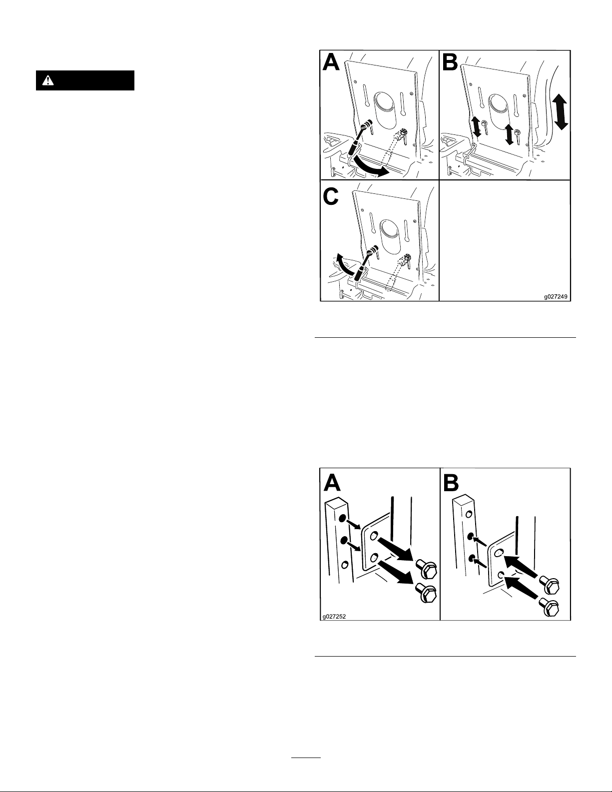
ReleasingtheMower-Deck Curtain
Loosenthe2bottomboltsofthecurtaintoaccessthetopof
themowerdeck(Figure32).
•Carefullyreleasepressurefromcomponentswithstored
energy.
•Disconnectthebatteryorremovethespark-plugwire
beforemakinganyrepairs.Disconnectthenegative
terminalrstandthepositiveterminallast.Connectthe
positiveterminalrstandnegativelast.
•Usecarewhencheckingtheblades.Wraptheblade(s)
orwearthicklypaddedgloves,andusecautionwhen
servicingthem.Onlyreplaceblades;donotstraighten
orweldthem.
•Keephandsandfeetawayfrommovingparts.Ifpossible,
donotmakeadjustmentswiththeenginerunning.
•Keepallpartsingoodworkingconditionandallhardware
tightened,especiallytheblade-attachmentbolts.Replace
allwornordamageddecals.
•Neverinterferewiththeintendedfunctionofasafety
deviceorreducetheprotectionprovidedbyasafety
device.Checktheirproperoperationregularly.
•Toensureoptimumperformanceandcontinuedsafety
certicationofthemachine,useonlygenuineToro
replacementpartsandaccessories.Replacementparts
andaccessoriesmadebyothermanufacturerscouldbe
dangerous,andsuchusecouldvoidtheproductwarranty.
Figure32
1.Bottombolt
Note:Alwaystightentheboltstoconnectthecurtainafter
maintenance.
2.Curtain
g027794
•Checktheparkingbrakeoperationfrequently.Adjustand
serviceasrequired.
28
Page 29

Lubrication
g020242
EngineMaintenance
GreasingtheBearings
ServiceInterval:Every25hours—Greasealllubrication
points.
GreaseType:No.2lithiumgrease
1.Parkthemachineonalevelsurfaceanddisengagethe
blade-controlswitch.
2.Movethemotion-controlleversoutwardtothePARK
position,shutofftheengine,removethekey,and
waitforallmovingpartstostopbeforeleavingthe
operatingposition.
3.Cleanthegreasettings(Figure33andFigure34)with
arag.
Note:Makesuretoscrapeanypaintoffthefrontof
thetting(s).
EngineSafety
Shutofftheenginebeforecheckingtheoiloraddingoilto
thecrankcase.
ServicingtheAirCleaner
ServiceInterval:Beforeeachuseordaily—Cleanandcheck
theaircleanerfoamelement.
Every50hours—Replacetheaircleanerpaper
element.
Note:Servicetheaircleanermorefrequently(everyfew
hours)ifoperatingconditionsareextremelydustyorsandy.
RemovingtheFoamandPaper
Elements
1.Parkthemachineonalevelsurface,disengagethe
blade-controlswitch(PTO),engagetheparkingbrake,
shutofftheengine,removethekey,andwaitforall
movingpartstostopbeforeleavingtheoperating
position..
Figure33
1.Frontcastertire
Figure34
Locatedontheseat-panunderside
1.Readtheinstructions
beforeservicingor
performingmaintenance.
2.Checkthetirepressure
every25operatinghours.
4.Connectagreaseguntoeachtting(Figure33and
Figure34).
3.Greaseevery25operating
hours.
4.Engine
2.Cleanaroundtheaircleanertopreventdirtfrom
gettingintotheengineandcausingdamage.
3.Removetheair-cleanercoverbyunscrewingthe2
knobs(Figure35).
g032432
decal106-8717
g020242
Figure35
1.Air-cleanercover2.Knobs
4.Carefullyremovethefoamandpaperlterelements
fromtheair-cleanerhousing(Figure36).
5.Pumpgreaseintothettingsuntilgreasebeginsto
oozeoutofthebearings.
29
Page 30

g020243
3
InstallingtheFoamandPaperElements
SAE 5W -30, 10W -30
SAE 30
SYNTHETIC 5W -20, 5W -30, 10W -30
g029683
Important:Topreventenginedamage,alwaysoperate
theenginewiththecompletefoamandpaperaircleaner
assemblyinstalled.
1.Installthefoamlterontothepaperlter(Figure36).
2.Installthefoamandpaperlterontotheair-cleaner
housing.
3.Installtheair-cleanercover,andtightenthe2knobs
(Figure35).
Figure36
1.Foamelement2.Paperelement
5.Separatethefoamandpaperelements.
CleaningtheFoamandPaperElements
FoamElement:
1.Washthefoamelementinliquidsoapandwarmwater.
2.Whentheelementisclean,rinseitthoroughly.
3.Drytheelementbysqueezingitinacleancloth.
Note:Donotoiltheelement.
Important:Replacethefoamelementifitistorn
orworn.
4.Installthefoamelementontoacleanpaperelement.
PaperElement:
1.Tapthepaperelementonasolid,atsurface,andblow
itoutfromtheinsidewithcompressedairtoremove
dustanddirt.
2.Inspecttheelementfortears,anoilylm,anddamage
totherubberseal.
Important:Donotcleanthepaperelementwith
liquids,suchassolvents,gasoline,orkerosene.
Replacethepaperelementifitisdamagedor
cannotbecleanedthoroughly.
3.Cleantheinsideoftheair-cleanercoverofalldirt,dust,
anddebris.
g020243
ServicingtheEngineOil
OilType:Detergentoil(APIserviceSF ,SG,SH,SJ,or
higher)
CrankcaseCapacity:withlter—1.4L(1.5USqt)
Viscosity:Seethetablebelow.
g029683
Figure37
CheckingtheEngine-OilLevel
ServiceInterval:Beforeeachuseordaily
Note:Checktheoilwhentheengineiscold.
WARNING
Contactwithhotsurfacesmaycausepersonal
injury.
Keephands,feet,face,clothing,andotherbody
partsawaythemuferandotherhotsurfaces.
Important:Donotoverllthecrankcasewithoil,
becausedamagetotheenginemayresult.Donotrun
enginewithoilbelowtheLowmark,becausetheengine
maybedamaged.
1.Parkthemachineonalevelsurface,disengagethe
blade-controlswitch,shutofftheengine,engagethe
parkingbrake,andremovethekey.
2.Makesurethattheengineisstopped,level,andiscool,
sotheoilhashadtimetodrainintothesump.
30
Page 31

3.Tokeepdirt,grassclippings,etc.,outoftheengine,
B
A
C
D
E
G029368
F
G H
I J K
B
A
C
E F
D
G
H
g029369
cleantheareaaroundtheoil-llcapanddipstickbefore
removingit(Figure38).
ChangingtheEngineOilandFilter
ServiceInterval:Aftertherst5hours
Every100hours(changeitmoreoftenunderaheavy
loadorinhightemperatures).
Every100hours
g029368
Figure38
g029369
Figure39
5.Changetheengine-oillter.
Note:Changetheengine-oilltermorefrequentlywhenthe
operatingconditionsareextremelydustyorsandy.
1.Parkthemachine,sothattherightsideisslightly
lowerthantheleftside,toensurethattheoildrains
completely.
2.DisengagethePTOandengagetheparkingbrake.
3.Shutofftheengine,waitforallmovingpartstostop,
andremovethekeybeforeleavingtheoperating
position.
4.Draintheoilfromtheengine.
Note:Ensuretheoil-ltergaskettouchestheengine,
andthenturnthelteranextra3/4turn.
31
Page 32

B
A
C D
E
F
3/4
g027477
Figure40
B
A
C
D
E
F
g027484
6.Slowlypourapproximately80%ofthespeciedoil
intothellertubeandslowlyaddtheadditionaloilto
bringittotheFullmark(Figure41).
g027484
Figure41
g027477
32
Page 33

ServicingtheSparkPlug
B
A
g027478
B
A
g027479
InstallingtheSparkPlug
ServiceInterval:Every50hours—Checkthesparkplug.
Every100hours—Replacethesparkplug.
Ensurethattheairgapbetweenthecenterandsideelectrodes
iscorrectbeforeinstallingthesparkplug.Useasparkplug
wrenchforremovingandinstallingthesparkpluganda
gappingtoolorfeelergaugetocheckandadjusttheairgap.
Installanewsparkplugifnecessary.
Type:Champion
BCPR6ES
AirGap:0.76mm(0.03inch)
®
RC12YC,Autolite
®
3924,orNGK
®
RemovingtheSparkPlug
1.Disengagetheblade-controlswitch,engagetheparking
brake,shutofftheengine,andremovethekey.
2.Beforeremovingthesparkplug(s),cleanthearea
aroundthebaseoftheplugtokeepdirtanddebrisout
oftheengine.
3.Removethesparkplug(Figure42).
Tightenthesparkplugto20N∙m(15ft-lb).
g027480
Figure44
Figure42
CheckingtheSparkPlug
Important:Donotcleanthesparkplug(s).Always
replacethesparkplug(s)whenithas:ablackcoating,
wornelectrodes,anoilylm,orcracks.
Note:Ifyouseelightbrownorgrayontheinsulator,the
engineisoperatingproperly.Ablackcoatingontheinsulator
usuallymeanstheaircleanerisdirty.
Setthegapto0.76mm(0.030inch).
Figure43
g027478
g027479
33
Page 34

CleaningtheBlowerHousing
FuelSystem
Toensurepropercooling,makesurethatthegrassscreen,
coolingns,andotherexternalsurfacesoftheengineare
keptcleanatalltimes.
Annually,orevery100hoursofoperation(moreoftenunder
extremelydusty,dirtyconditions),removetheblowerhousing
andanyothercoolingshrouds.Cleanthecoolingnsand
externalsurfacesasnecessary.Makesurethatthecooling
shroudsareinstalled.Torquetheblowerhousingscrewsto
7.5N∙m(5.5ft-lb).
Important:Operatingtheenginewithablocked
grassscreen,dirtyorpluggedcoolingns,and/or
coolingshroudsremoved,causesenginedamagedue
tooverheating.
Maintenance
DANGER
Incertainconditions,fuelisextremelyammable
andhighlyexplosive.Areorexplosionfromfuel
canburnyou,others,andcandamageproperty.
•Performanyfuel-relatedmaintenancewhenthe
engineiscold.Dothisoutdoorsinanopenarea.
Wipeupanyfuelthatspills.
•Neversmokewhendrainingfuel,andstayaway
fromanopenameorwhereasparkmayignite
thefuelfumes.
ReplacingtheIn-LineFuel Filter
ServiceInterval:Every100hours/Yearly(whichevercomes
rst)—Checkthein-linefuellter.
Every200hours/Every2years(whichevercomes
rst)—Replacethein-linefuellter.
Neverinstalladirtylterifitisremovedfromthefuelline.
1.Parkthemachineonalevelsurfaceanddisengagethe
blade-controlswitch.
2.Ensurethatthebrakeisengaged,shutofftheengine,
removethekey ,andwaitforallmovingpartstostop
beforeleavingtheoperatingposition.
34
Page 35

g027506
ElectricalSystem
Maintenance
ElectricalSystemSafety
•Disconnectthebatterybeforerepairingthemachine.
g027506
Disconnectthenegativeterminalrstandthepositive
last.Connectthepositiveterminalrstandthenegative
last.
•Chargethebatteryinanopen,well-ventilatedarea,away
fromsparksandames.Unplugthechargerbefore
connectingordisconnectingthebattery.Wearprotective
clothinganduseinsulatedtools.
WARNING
CALIFORNIA
Proposition65Warning
Batteryposts,terminals,andrelated
accessoriescontainleadandleadcompounds,
chemicalsknowntotheStateofCalifornia
tocausecancerandreproductiveharm.
Washhandsafterhandling.
Figure45
ServicingtheBattery
RemovingtheBattery
WARNING
g033082
Batteryterminalsormetaltoolscouldshortagainst
metalmachinecomponentscausingsparks.Sparks
cancausethebatterygassestoexplode,resulting
inpersonalinjury.
•Whenremovingorinstallingthebattery,donot
allowthebatteryterminalstotouchanymetal
partsofthemachine.
•Donotallowmetaltoolstoshortbetween
thebatteryterminalsandmetalpartsofthe
machine.
1.Parkthemachineonalevelsurfaceanddisengagethe
blade-controlswitch.
2.Movethemotion-controlleversoutwardtothePARK
position,shutofftheengine,removethekey,and
waitforallmovingpartstostopbeforeleavingthe
operatingposition.
3.Raisetheseattoaccessthebattery.
4.Disconnectthenegative(black)groundcablefromthe
batterypost(Figure46).
Note:Retainallfasteners.
35
Page 36

WARNING
G005072
1
2
3
4
5
6
7
Incorrectbattery-cableroutingcoulddamage
themachineandcablescausingsparks.
Sparkscancausethebatterygassesto
explode,resultinginpersonalinjury.
ChargingtheBattery
ServiceInterval:Beforestorage—Chargethebatteryand
disconnectthebatterycables.
1.Removethebatteryfromthechassis;refertoRemoving
theBattery(page35).
•Alwaysdisconnectthenegative(black)
batterycablebeforedisconnectingthe
positive(red)cable.
•Alwaysconnectthepositive(red)battery
cablebeforeconnectingthenegative
(black)cable.
5.Slidetherubbercoverupthepositive(red)cable.
6.Disconnectthepositive(red)cablefromthebattery
post(Figure46).
Note:Retainallfasteners.
7.Removethebatteryhold-down(Figure46),andliftthe
batteryfromthebatterytray .
2.Chargethebatteryforaminimumof1hourat6to
10A.
Note:Donotoverchargethebattery.
3.Whenthebatteryisfullycharged,unplugthecharger
fromtheelectricaloutlet,thendisconnectthecharger
leadsfromthebatteryposts(Figure47).
g000538
Figure47
1.Positive(+)batterypost3.Red(+)chargerlead
2.Negative(–)batterypost4.Black(–)chargerlead
1.Battery
2.Positive(+)batterypost
3.Bolt,washer,andnut7.Batteryhold-down
4.Terminalboot
InstallingtheBattery
1.Positionthebatteryinthetray(Figure46).
2.Usingthefastenerspreviouslyremoved,installthe
positive(red)batterycabletothepositive(+)battery
terminal.
3.Usingthefastenerspreviouslyremoved,installthe
g005072
Figure46
5.Negative(–)batterypost
6.Wingnut,washer,andbolt
negativebatterycabletothenegative(-)battery
terminal.
4.Slidetheredterminalbootontothepositive(red)
batterypost.
5.Securethebatterywiththehold-down(Figure46).
6.Lowertheseat.
36
Page 37

ServicingtheFuses
30
25
30
25
G014540
2
1
DriveSystem
Theelectricalsystemisprotectedbyfuses.Itrequires
nomaintenance;however,ifafuseblows,checkthe
component/circuitforamalfunctionorshort.
Fusetype:
•Main—F1(30A,blade-type)
•ChargeCircuit—F2(25A,blade-type)
1.Removethescrewssecuringthecontrolpaneltothe
machine.
Note:Retainallfasteners.
2.Liftthecontrolpaneuptoaccessthemainwireharness
andfuseblock(Figure48).
3.Toreplaceafuse,pulloutonthefusetoremoveit
(Figure48).
Maintenance
CheckingtheTirePressure
ServiceInterval:Every25hours—Checktirepressure.
Maintaintheairpressureinthefrontandreartiresas
specied.Uneventirepressurecancauseunevencut.Check
thepressureatthevalvestem(Figure49).Checkthetires
whentheyarecoldtogetthemostaccuratepressurereading.
Refertothemaximumpressuresuggestedbythetire
manufactureronthesidewallofthecasterwheeltires.
Inatethereardrivewheeltiresto90kPa(13psi).
g000554
Figure49
Figure48
1.Main(30A)2.Chargecircuit(25A)
4.Returnthecontrolpaneltoitsoriginalposition.
Note:Usethescrewsremovedpreviouslytosecure
thepaneltothemachine.
1.Valvestem
g014540
37
Page 38

ReleasingtheElectricBrake
Youcanmanuallyreleasetheelectricbrakebyrotatingthe
linkarmsforward.Oncetheelectricbrakeisenergized,the
brakeresets.
1.TurntheignitionkeytotheOFFpositionordisconnect
thebattery.
2.Loosenthebottom2boltsholdingthemower-deck
curtaintothemowerdeck.RefertoReleasingthe
Mower-DeckCurtain(page28).
3.Locatetheshaftontheelectricbrakewherethebrake
linkarmsareconnected(Figure50).
4.Rotatetheshaftforwardtoreleasethebrake.
5.Tightenthebottom2boltsforthemower-deckcurtain
tothemowerdeck.RefertoReleasingtheMower-Deck
Curtain(page28).
MowerMaintenance
ServicingtheCuttingBlades
Toensureasuperiorqualityofcut,keepthebladessharp.For
convenientsharpeningandreplacement,keepextrablades
onhand.
BladeSafety
Awornordamagedbladecanbreak,andapieceoftheblade
couldbethrowntowardyouorbystanders,resultinginserious
personalinjuryordeath.Tryingtorepairadamagedblade
mayresultindiscontinuedsafetycerticationoftheproduct.
•Inspectthebladesperiodicallyforwearordamage.
•Usecarewhencheckingtheblades.Wrapthebladesor
weargloves,andusecautionwhenservicingtheblades.
Onlyreplaceorsharpentheblades;neverstraightenor
weldthem.
•Onmulti-bladedmachines,takecareasrotating1blade
cancauseotherbladestorotate.
BeforeInspectingorServicingthe
Blades
1.Parkthemachineonalevelsurface,disengage
theblade-controlswitch(PTO),andmovethe
motion-controlleversoutwardtothePARKposition.
2.Shutofftheengine,removethekey,anddisconnectthe
spark-plugwiresfromthesparkplugs.
Figure50
1.Brake-linkarmontheelectricbrakecontrolmodule
2.Left,reartire
g027911
InspectingtheBlades
ServiceInterval:Beforeeachuseordaily
1.Inspectthecuttingedges(Figure51).
2.Iftheedgesarenotsharporhavenicks,removeand
sharpentheblade;refertoSharpeningtheBlades(page
40).
3.Inspecttheblades,especiallyinthecurvedarea.
4.Ifyounoticeanycracks,wear,oraslotforminginthis
area,immediatelyinstallanewblade(Figure51).
g006530
Figure51
1.Cuttingedge3.Wear/slotforming
2.Curvedarea4.Crack
38
Page 39

CheckingforBentBlades
G009679
1
2
3
G009680
1
2
3
G009681
1
2
3
G009680
1
2
3
Note:Themachinemustbeonalevelsurfaceforthe
followingprocedure.
1.Raisethemowerdecktothehighestheight-of-cut
position.
2.Whilewearingthicklypaddedgloves,orotheradequate
handprotection,slowlyrotatethebladetobemeasure
intoapositionthatallowseffectivemeasurementofthe
distancebetweenthecuttingedgeandthelevelsurface
themachineison(Figure52).
Figure52
1.Deck3.Blade
2.Spindlehousing
g009681
Figure54
1.Blade(sidepreviouslymeasured)
2.Measurement(positionusedpreviously)
3.Opposingsideofbladebeingmovedintomeasurement
position
5.Measurefromthetipofthebladetotheatsurface
(Figure55).
Note:Thevarianceshouldbenomorethan3mm
g009679
(1/8inch).
3.Measurefromthetipofthebladetotheatsurface
(Figure53).
Figure53
1.Blade(inpositionformeasuring)
2.Levelsurface
3.Measureddistancebetweenbladeandthesurface(A)
4.Rotatethesameblade180degreessothattheopposing
cuttingedgeisnowinthesameposition(Figure54).
g009680
Figure55
1.Oppositebladeedge(inpositionformeasuring)
2.Levelsurface
3.Secondmeasureddistancebetweenbladeandsurface(B)
g009680
A.IfthedifferencebetweenAandBisgreaterthan
3mm(1/8inch),replacethebladewithanew
blade;refertoRemovingtheBlades(page40)and
SharpeningtheBlades(page40).
Note:Ifabentbladeisreplacedwithanew
blade,andthedimensionobtainedcontinuesto
exceed3mm(1/8inch),thebladespindlecould
bebent.ContactanAuthorizedToroDealerfor
service.
B.Ifthevarianceiswithinconstraints,movetothe
nextblade.
6.Repeatthisprocedureoneachblade.
39
Page 40

RemovingtheBlades
G027833
SharpeningtheBlades
Thebladesmustbereplacedifasolidobjectishit,iftheblade
isoutofbalance,orifthebladeisbent.Forbestperformance
andcontinuedsafetyconformanceofthemachine,use
genuineT ororeplacementblades.Replacementbladesmade
byothermanufacturersmayresultinnon-conformancewith
safetystandards.
1.Holdthebladeendusingaragorthickly-paddedglove.
2.Removethebladestiffener(32-inchdecksonly),blade
bolt,thecurvedwasher,andthebladefromthespindle
shaft(Figure56andFigure57).
Figure56
81cm(32-Inch)Decks
1.Usealetosharpenthecuttingedgeatbothendsof
theblade(Figure58).
Note:Maintaintheoriginalangle.
Note:Thebladeretainsitsbalanceifthesameamount
ofmaterialisremovedfrombothcuttingedges.
g000552
Figure58
1.Sharpenatoriginalangle.
2.Checkthebalanceofthebladebyputtingitonablade
balancer(Figure59).
Note:Ifthebladestaysinahorizontalposition,the
bladeisbalancedandcanbeused.
g000551
Note:Ifthebladeisnotbalanced,lesomemetaloff
theendofthesailareaonly(Figure58).
1.Sailareaoftheblade
2.Blade
3.Curvedwasher
107cm(42-Inch)Decks
1.Sailareaoftheblade3.Curvedwasher
2.Blade4.Bladebolt
4.Bladebolt
5.Bladestiffener
Figure57
g000553
Figure59
1.Blade2.Balancer
3.Repeatthisprocedureuntilthebladeisbalanced.
InstallingtheBlades
1.Installthebladeontothespindleshaft(Figure57).
Important:Thecurvedpartoftheblademustbe
pointingupwardtowardtheinsideofthemowerto
ensurepropercutting.
2.Installthebladestiffener(32-inchdecksonly),curved
g027833
washer(cuppedsidetowardtheblade),andbladebolt
(Figure57).
3.Torquethebladeboltto47to88N∙m(35to65ft-lb).
40
Page 41

LevelingtheMowerDeck
G014630
1
2
3
4
4
G009682
1
2
2
3
3
4
4
Checktoensurethatthemowerdeckislevelanytimeyou
installthemowerorwhenyouseeanunevencutonyour
lawn.
Themowerdeckmustbecheckedforbentbladespriorto
leveling;anybentbladesmustberemovedandreplaced;refer
totheCheckingforBentBlades(page39)beforecontinuing.
Themowerdeckmustbeleveledside-to-siderstthenthe
fronttorearslopecanbeadjusted.
Requirements:
•Themachinemustbeonalevelsurface.
•Alltiresmustbeproperlyinated;refertoCheckingthe
TirePressure(page37).
LevelingfromSidetoSide
1.Parkthemachineonalevelsurfaceanddisengagethe
blade-controlswitch.
2.Movethemotion-controlleversoutwardtothePARK
position,shutofftheengine,removethekey,and
waitforallmovingpartstostopbeforeleavingthe
operatingposition.
3.Settheheight-of-cutlevertothemiddleposition.
4.Carefullyrotatetheblade(s)sothattheyareallsideto
side(Figure60andFigure61).
Figure61
MowerDeckswith2Blades
1.Bladessidetoside
2.Sailareaofblade4.Measurefromthetipofthe
3.Outsidecuttingedges
bladetotheatsurface
here.
5.Measurebetweentheoutsidecuttingedgesandtheat
surface(Figure60andFigure61).
Note:Ifbothmeasurementsarenotwithin5mm
(3/16inch),anadjustmentisrequired;continuewith
thisprocedure.
6.Movetotheleftsideofthemachine.
7.Loosenthesidelockingnut.
8.Raiseorlowertheleftsideofthemowerdeckby
rotatingtherearnut(Figure62).
g009682
Note:Rotatetherearnutclockwisetoraisethemower
deck;rotatetherearnutcounter-clockwisetolowerthe
mowerdeck(Figure62).
g014630
Figure60
MowerDeckswith1Blade
1.Bladesidetoside
2.Sailareaoftheblade4.Measurefromthetipofthe
3.Outsidecuttingedges
bladetotheatsurface
here.
g027588
Figure62
1.Hangerbracket3.Rearlockingnut
2.Sidelockingnut
41
Page 42

9.Checktheside-to-sideadjustmentsagain;repeatthis
G014631
1
2
2
G009658
1
2
2
G014634
1
2
3
procedureuntilthemeasurementsarecorrect.
10.Continuelevelingthedeckbycheckingthefront-to-rear
bladeslope;refertoAdjustingtheFront-to-RearBlade
Slope(page42).
AdjustingtheFront-to-RearBlade
Slope
Checkthefront-to-rearbladelevelanytimeyouinstallthe
mower.Ifthefrontofthemowerismorethan7.9mm
(5/16inch)lowerthantherearofthemower,adjusttheblade
levelusingthefollowinginstructions:
1.Parkthemachineonalevelsurfaceanddisengagethe
blade-controlswitch.
g009658
Figure64
MowerDeckswith2Blades
1.Bladesfronttorear
2.Measurefromthetipofthebladetotheatsurfacehere.
2.Movethemotion-controlleversoutwardtothePARK
position,shutofftheengine,removethekey,and
waitforallmovingpartstostopbeforeleavingthe
operatingposition.
3.Settheheight-of-cutlevertomiddleposition.
Note:Checkandadjusttheside-to-sidebladelevel
ifyouhavenotcheckedthesetting;refertoLeveling
fromSidetoSide(page41).
4.Carefullyrotatethebladessotheyarefacingfrontto
rear(Figure63andFigure64).
5.Measurefromthetipofthefrontbladetotheat
surface,andthetipoftherearbladetotheatsurface
(Figure63andFigure64).
Note:Ifthefrontbladetipisnot1.6to7.9mm(1/16
to5/16inch)lowerthantherearbladetip,adjustthe
frontlocknut.
6.Toadjustthefront-to-rearbladeslope,rotatethe
adjustmentnutinthefrontofthemower(Figure65).
Figure63
MowerDeckswith1Blade
1.Bladefronttorear
2.Measurefromthetipofthebladetotheatsurfacehere.
g014631
1.Adjustingrod3.Locknut
2.Adjustingblock
Figure65
g014634
7.Toraisethefrontofthemower,tightentheadjustment
nut.
8.Tolowerthefrontofthemower,loosentheadjustment
nut.
9.Afteradjustment,checkthefront-to-rearslopeagain,
continueadjustingthenutuntilthefrontbladetipis
1.6to7.9mm(1/16to5/16inch)lowerthantherear
bladetip(Figure64andFigure65).
42
Page 43

10.Whenthefront-to-rearbladeslopeiscorrectcheckthe
G014635
1
2
3
G015338
2
2
3
1
2
2
3
side-to-sidelevelofthemoweragain,refertoLeveling
fromSidetoSide(page41).
RemovingtheMowerDeck
1.Parkthemachineonalevelsurfaceanddisengagethe
blade-controlswitch.
2.Movethemotion-controlleversoutwardtothePARK
position,shutofftheengine,removethekey,and
waitforallmovingpartstostopbeforeleavingthe
operatingposition.
3.Lowertheheight-of-cutlevertothelowestposition.
4.Loosenthebottom2boltsholdingthemower-deck
curtaintothemowerdeck.RefertoReleasingthe
Mower-DeckCurtain(page28).
g015338
Figure67
5.Removethehairpin-cotterpinfromthefrontsupport
rod,andremovetherodfromthedeckbracket(Figure
66).
Figure66
1.Frontsupportrod3.Deckbracket
2.Lockingnut
1.Mowerdeck
2.Hangerbracket
3.Rearliftrod
8.Slidethemowerdeckrearwardtoremovethemower
beltfromtheenginepulley.
9.Slidethemowerdeckoutfromunderneaththe
machine.
Note:Retainallpartsforfutureinstallation.
InstallingtheMowerDeck
1.Parkthemachineonalevelsurfaceanddisengagethe
blade-controlswitch.
2.Movethemotion-controlleversoutwardtothePARK
position,shutofftheengine,removethekey,and
waitforallmovingpartstostopbeforeleavingthe
operatingposition.
3.Slidethemowerunderthemachine.
4.Lowertheheight-of-cutlevertothelowestposition.
5.Lifttherearofthemowerdeckandguidethehanger
g014635
bracketsovertherearliftrod(Figure67).
6.Attachthefrontsupportrodtothemowerdeckwith
theclevispinandhairpin-cotterpin(Figure66).
7.Installthemowerbeltontotheenginepulley;referto
ReplacingtheMowerBelt(page45).
6.Carefullylowerthefrontofthemowerdecktothe
ground.
7.Liftthemowerdeckandhangerbracketsclearof
8.Tightenthebottom2boltsforthemower-deckcurtain
tothemowerdeck.RefertoReleasingtheMower-Deck
Curtain(page28).
therearliftrodandlowerthemowercarefullytothe
ground(Figure67).
43
Page 44

ReplacingtheGrassDeector
G014636
1
2
3
4
5
6
7
G005192
1
2
3
4
5
6
7
ServiceInterval:Beforeeachuseordaily—Inspectthegrass
deectorfordamage.
WARNING
Anuncovereddischargeopeningcouldallowthe
lawnmowertothrowobjectsatyouorbystanders,
resultinginseriousinjury.Also,contactwiththe
bladecouldoccur.Neveroperatethemachine
withoutthegrassdeector,thedischargecover,or
thegrass-collectionsysteminplace.
Neveroperatethemachinewithoutthegrass
deector,thedischargecover,orthegrass-collection
systeminplace.
1.Removethenut(3/8inch)fromtherodunderthe
mower(Figure68andFigure69).
Figure69
107cm(42-Inch)Deck
1.Mowerdeck
2.Grassdeector6.Nut(3/8inch)
3.Grass-deectorbracket7.Shortstandoff
4.Rod
5.Spring
g005192
Figure68
81cm(32-Inch)Deck
1.Mowerdeck
2.Grassdeector6.Nut(3/8inch)
3.Grass-deectorbracket7.Shortstandoff
4.Rod
5.Spring
2.Slidetherodoutoftheshortstand-off,spring,and
grassdeector(Figure68andFigure69).
3.Removethedamagedorworngrassdeector.
4.Replacethegrassdeector(Figure68andFigure69).
5.Slidetherod(straightend),throughthe
rear-grass-deectorbracket.
6.Placethespringontherod,withtheendwiresdown,
andbetweenthegrassdeectorbrackets.
g014636
7.Slidetherodthroughsecondgrassdeectorbracket
(Figure68andFigure69).
8.Inserttherodatthefrontofthegrassdeectorinto
theshortstandoffonthedeck.
9.Securetherearendoftherodintothemowerwitha
nut(3/8inch)asshowninFigure68andFigure69.
Important:Thegrassdeectormustbespring
loadedinthedownposition.Liftthedeectorup
totestthatitsnapstothefulldownposition.
44
Page 45

MowerBeltMaintenance
G015129
1
2
3
4
5
4
6
G014930
1
2
3
3
4
5
1
2
3
3
4
5
6
4
InspectingtheBelts
ServiceInterval:Every25hours—Checkthebeltsforwear
orcracks.
Checkthebeltsforcracks,frayededges,burnmarks,orany
otherdamage.Replacedamagedbelts.
ReplacingtheMowerBelt
Squealingwhenthebeltisrotating,bladesslippingwhen
cuttinggrass,frayedbeltedges,burnmarks,andcracksare
signsofawornmowerbelt.Replacethemowerbeltifanyof
theseconditionsareevident.
1.Parkthemachineonalevelsurfaceanddisengagethe
blade-controlswitch.
2.Movethemotion-controlleversoutwardtothePARK
position,shutofftheengine,removethekey,and
waitforallmovingpartstostopbeforeleavingthe
operatingposition.
3.Settheheightofcutatthelowestcuttingposition(38
mm(1-1/2inches).
4.Removethepulleycovers(Figure70).
Figure71
MowerDeckswith1Blade
1.Idlerpulley
2.Mowerbelt5.Enginepulley
3.Outsidepulley6.Spring-removaltool
4.Spring
g015129
Figure70
Modelwith107cm(42-inch)DeckOnly
1.Cover2.Screw
5.Loosenthebottom2boltsholdingthemower-deck
curtaintothemowerdeck;refertoReleasingthe
Mower-DeckCurtain(page28).
6.Usingaspring-removaltool(Toropartno.92-5771),
removetheidlerspringfromthedeckhooktoremove
tensionontheidlerpulley,androllthebeltoffofthe
pulleys(Figure71andFigure72).
WARNING
Thespringisundertensionwheninstalled
andcancausepersonalinjury.
Becarefulwhenremovingthebelt.
g032555
g014930
Figure72
MowerDeckswith2Blades
1.Idlerpulley
2.Mowerbelt5.Enginepulley
3.Outsidepulley6.Spring-removaltool
45
4.Spring
Page 46

7.Routethenewbeltaroundtheenginepulleyand
mowerpulleys(Figure71andFigure72).
8.Usingaspring-removaltool(Toropartno.92-5771),
installtheidlerspringoverthedeckhookandplace
tensionontheidlerpulleyandthemowerbelt(Figure
71andFigure72).
9.Tightenthebottom2boltsholdingthemower-deck
curtaintothemowerdeck;refertoReleasingthe
Mower-DeckCurtain(page28).
10.Installthepulleycovers.
Cleaning
WashingtheUndersideofthe Mower
ServiceInterval:Aftereachuse—Cleanthemower-deck
housing.
Important:Y oucanwashthemachinewithamild
detergentandwater.Donotpressurewashthemachine.
Avoidexcessiveuseofwater,especiallynearthecontrol
panel,undertheseat,aroundtheengine,hydraulic
pumps,andmotors.
Washtheundersideofthemoweraftereachusetoprevent
grassbuildupforimprovedmulchactionandclipping
dispersal.
1.Parkthemachineonalevelsurfaceanddisengagethe
blade-controlswitch.
2.Movethemotion-controlleversoutwardtothePARK
position,shutofftheengine,removethekey,and
waitforallmovingpartstostopbeforeleavingthe
operatingposition.
3.Attachthehosecouplingtotheendofthemower
washouttting,andturnthewateronhigh(Figure73).
Note:Spreadpetroleumjellyonthewashouttting
O-ringtomakethecouplingslideoneasierandprotect
theO-ring.
Figure73
1.Washouttting3.O-ring
2.Hose
4.Coupling
g003934
4.Lowerthemowertothelowestheight-of-cut.
5.Sitontheseatandstarttheengine.
6.Engagetheblade-controlswitchandletthemowerrun
for1to3minutes.
46
Page 47

7.Disengagetheblade-controlswitch,shutoffthe
engine,removetheignitionkey,andwaitforallmoving
partstostop.
8.Turnthewateroffandremovethecouplingfromthe
washouttting.
Note:Ifthemowerisnotcleanafter1washing,soak
itandletitstandfor30minutes.Then,repeatthe
process.
9.Runthemoweragainfor1to3minutestoremove
excesswater.
WARNING
Abrokenormissingwashoutttingcould
exposeyouandotherstothrownobjectsor
bladecontact.Contactwithabladeorthrown
debriscancauseinjuryordeath.
•Replacebrokenormissingwashouttting
immediately,beforeusingmoweragain.
•Neverputyourhandsorfeetunderthe
mowerorthroughopeningsinthemower.
Storage
CleaningandStorage
1.Disengagetheblade-controlswitch,movethe
motion-controlleversoutwardtothePARKposition,
shutofftheengine,andremovethekey .
2.Removegrassclippings,dirt,andgrimefromthe
externalpartsoftheentiremachine,especiallythe
engine.Cleandirtandchafffromtheoutsideofthe
enginecylinderheadnsandblowerhousing.
Important:Youcanwashthemachinewithmild
detergentandwater.Donotpressurewashthe
machine.Avoidexcessiveuseofwater,especially
nearthecontrolpanel,undertheseat,aroundthe
engine,hydraulicpumps,andmotors.
3.Servicetheaircleaner;refertoServicingtheAir
Cleaner(page29).
4.Greaseandoilthemachine;refertoLubrication(page
29).
5.Changetheengineoilandlter;refertoChangingthe
EngineOilandFilter(page31).
6.Checkthetirepressure;refertoCheckingtheTire
Pressure(page37).
7.Chargethebattery;refertoChargingtheBattery(page
36).
8.Checktheconditionoftheblades;refertoServicing
theCuttingBlades(page38).
9.Preparethemachineforstoragewhennon-useoccurs
over30days.Preparethemachineforstorageas
follows.
A.Addapetroleumbasedstabilizer/conditionerto
thefuelinthetank.Followthemixinginstructions
fromthestabilizermanufacturer.Donotusean
alcoholbasedstabilizer(ethanolormethanol).
Note:Afuelstabilizer/conditionerismost
effectivewhenmixedwithfreshfuelandusedat
alltimes.
B.Runtheenginetodistributetheconditionedfuel
throughthefuelsystem(5minutes).
C.Shutofftheengine,waitforittocool,anddrain
thefueltank.
D.Restarttheengineandrunituntilitstops.
E.Startandruntheengineuntilitdoesnotstart.
F.Disposeoffuelproperly .Recyclepursuantto
localcodes.
Important:Donotstorefuelwith
stabilizer/conditionerover90days.
10.Removethesparkplug(s)andcheckitscondition;
refertoServicingtheSparkPlug(page33).Withthe
sparkplug(s)removedfromtheengine,pour30ml
(2tablespoons)ofengineoilintothesparkplughole.
47
Page 48

Usethestartertocranktheengineanddistributethe
oilinsidethecylinder.Installthesparkplug(s).Donot
installthewireonthesparkplug(s).
11.Cleananydirtandchafffromthetopofthemower.
12.Scrapeanyheavybuildupofgrassanddirtfromthe
undersideofthemower,thenwashthemowerwith
agardenhose.
13.Checktheconditionofthedriveandmowerbelts.
14.Checkandtightenallbolts,nuts,andscrews.Repairor
replaceanypartthatiswornordamaged.
15.Paintallscratchedorbaremetalsurfaces.Paintis
availablefromyourAuthorizedServiceDealer.
16.Storethemachineinaclean,drygarageorstoragearea.
Removethekeyfromtheignitionswitchandkeepit
inamemorableplace.Coverthemachinetoprotect
itandkeepitclean.
48
Page 49

Troubleshooting
Problem
Theengineoverheats.
Thestarterdoesnotcrank.
Theenginedoesnotstart,startshard,or
failstokeeprunning.
PossibleCauseCorrectiveAction
1.Theengineloadisexcessive.1.Reducethegroundspeed.
2.Theoillevelinthecrankcaseislow.2.Addoiltothecrankcase.
3.Thecoolingnsandairpassages
undertheengine-blowerhousingare
plugged.
4.Theaircleanerisdirty .
5.Dirt,water,orstalefuelisinthefuel
system.
1.Theblade-controlswitchisengaged.1.Movetheblade-controlswitchto
2.Themotion-controlleversarenotin
thePARKposition.
3.Thebatteryisdead.
4.Theelectricalconnectionsare
corrodedorloose.
5.Afuseisblown.5.Replacethefuse.
6.Arelayorswitchisdamaged.
1.Thefueltankisempty .1.Fillthefueltank.
2.Thechokeisnoton.
3.Theaircleanerisdirty .
4.Thespark-plugwire(s)islooseor
disconnected.
5.Thesparkplug(s)ispitted,fouled,or
thegapisincorrect.
6.Thereisdirtinfuellter.6.Replacethefuellter.
7.Dirt,water,orstalefuelisinfuel
system.
8.Thereisincorrectfuelinthefueltank.8.Drainthetankandreplacethefuelwith
9.Theoillevelinthecrankcaseislow.9.Addoiltothecrankcase.
3.Removetheobstructionfromthe
coolingnsandairpassages.
4.Cleanorreplacetheair-cleaner
element.
5.ContactanAuthorizedServiceDealer
Disengaged.
2.Movethemotion-controllevers
outwardtothePARKposition.
3.Chargethebattery.
4.Checktheelectricalconnectionsfor
goodcontact.
6.ContactanAuthorizedServiceDealer.
2.MovethechokelevertoOn.
3.Cleanorreplacetheair-cleaner
element.
4.Installthewire(s)onthesparkplug.
5.Installanew,correctlygappedspark
plug(s).
7.ContactanAuthorizedServiceDealer.
thepropertype.
Themachinedoesnotdrive.
Thereisanabnormalvibration.
1.Thebypassvalvesareopen.
2.Thetractionbeltsareworn,loose,or
broken.
3.Thetractionbeltsareoffofthepulleys.3.ContactanAuthorizedServiceDealer.
4.Thetransmissionhasfailed.4.ContactanAuthorizedServiceDealer.
1.Theengine-mountingboltsareloose.1.Tightentheengine-mountingbolts.
2.Theenginepulley,idlerpulley,orblade
pulleyisloose.
3.Theenginepulleyisdamaged.
4.Thecuttingblade(s)is/arebentor
unbalanced.
5.Ablade-mountingboltisloose.5.Tightentheblade-mountingbolt.
6.Abladespindleisbent.
1.Closethetowvalves.
2.ContactanAuthorizedServiceDealer.
2.Tightentheappropriatepulley.
3.ContactanAuthorizedServiceDealer.
4.Installanewcuttingblade(s).
6.ContactanAuthorizedServiceDealer.
49
Page 50

Problem
PossibleCauseCorrectiveAction
Thecuttingheightisuneven.
Thebladesdonotrotate.
1.Theblade(s)isnotsharp.1.Sharpentheblade(s).
2.Acuttingblade(s)is/arebent.2.Installanewcuttingblade(s).
3.Themowerisnotlevel.
4.Ananti-scalpwheelisnotsetcorrectly .4.Adjusttheanti-scalpwheelheight.
5.Theundersideofthemowerisdirty.5.Cleantheundersideofthemower.
6.Thetirepressureisincorrect.6.Adjustthetirepressure.
7.Abladespindleisbent.
1.Thedrivebeltisworn,looseorbroken.1.Installanewdrivebelt.
2.Thedrivebeltisoffofthepulley.
3.ThePowerTake-Off(PTO)switchor
PTOclutchisfaulty.
4.Themowerbeltisworn,loose,or
broken.
3.Levelthemowerfromside-to-sideand
front-to-rear.
7.ContactanAuthorizedServiceDealer.
2.Installthedrivebeltandcheckthe
adjustingshaftsandbeltguidesforthe
correctposition.
3.ContactanAuthorizedServiceDealer.
4.Installanewmowerbelt.
50
Page 51

Schematics
ElectricalDiagram(Rev .A)
51
g028022
Page 52

Notes:
Page 53

Notes:
Page 54

Notes:
Page 55

EuropeanPrivacyNotice
TheInformationToroCollects
ToroWarrantyCompany(T oro)respectsyourprivacy.Inordertoprocessyourwarrantyclaimandcontactyouintheeventofaproductrecall,weaskyou
tosharecertainpersonalinformationwithus,eitherdirectlyorthroughyourlocalT orocompanyordealer.
TheT orowarrantysystemishostedonserverslocatedwithintheUnitedStateswhereprivacylawmaynotprovidethesameprotectionasapplies
inyourcountry.
BYSHARINGYOURPERSONALINFORMATIONWITHUS,YOUARECONSENTINGTOTHEPROCESSINGOFYOURPERSONALINFORMATION
ASDESCRIBEDINTHISPRIV ACYNOTICE.
TheWayT oroUsesInformation
Toromayuseyourpersonalinformationtoprocesswarrantyclaims,tocontactyouintheeventofaproductrecallandforanyotherpurposewhichwetell
youabout.ToromayshareyourinformationwithT oro'safliates,dealersorotherbusinesspartnersinconnectionwithanyoftheseactivities.Wewillnot
sellyourpersonalinformationtoanyothercompany.Wereservetherighttodisclosepersonalinformationinordertocomplywithapplicablelawsand
withrequestsbytheappropriateauthorities,tooperateoursystemsproperlyorforourownprotectionorthatofotherusers.
RetentionofyourPersonalInformation
Wewillkeepyourpersonalinformationaslongasweneeditforthepurposesforwhichitwasoriginallycollectedorforotherlegitimatepurposes
(suchasregulatorycompliance),orasrequiredbyapplicablelaw .
Toro'sCommitmenttoSecurityofYourPersonalInformation
Wetakereasonableprecautionsinordertoprotectthesecurityofyourpersonalinformation.Wealsotakestepstomaintaintheaccuracyandcurrent
statusofpersonalinformation.
AccessandCorrectionofyourPersonalInformation
Ifyouwouldliketorevieworcorrectyourpersonalinformation,pleasecontactusbyemailatlegal@toro.com.
AustralianConsumerLaw
AustraliancustomerswillnddetailsrelatingtotheAustralianConsumerLaweitherinsidetheboxoratyourlocalT oroDealer.
374-0282RevC
Page 56

TheT oroWarranty
TheToroGTSStartingGuarantee
ResidentialProducts
and
ConditionsandProductsCovered
TheT oroCompanyanditsafliate,T oroWarrantyCompany,pursuantto
anagreementbetweenthem,jointlypromisetorepairtheToroProduct
listedbelowifdefectiveinmaterialsorworkmanshiporiftheToroGTS
(GuaranteedtoStart)enginewillnotstartontherstorsecondpull,
providedtheroutinemaintenancerequiredintheOperator'sManualhave
beenperformed.
Thefollowingtimeperiodsapplyfromtheoriginaldateofpurchase:
ProductsWarrantyPeriod
WalkPowerMowers
•CastDeck
5yearsResidentialUse
2
90DaysCommercialUse
—Engine
5yearsGTSGuarantee,
ResidentialUse
3
—Battery2years
•SteelDeck
2yearsResidentialUse
2
30DaysCommercialUse
—Engine
TimeMasterMowers3yearsResidentialUse
2yearsGTSGuarantee,
ResidentialUse
3
2
90DaysCommercialUse
•Engine
3yearsGTSGuarantee,
ResidentialUse
3
•Battery2years
ElectricHandHeldProducts
andWalkPowerMowers
2yearsResidentialUse
NoWarrantyforCommercialUse
2
AllRide-OnUnitsBelow
•Engine
•Battery2yearsResidentialUse
•Attachments2yearsResidentialUse
DHLawn&GardenTractors
Seeenginemanufacturer'swarranty
2yearsResidentialUse
2
2
2
30DaysCommercialUse
XLSLawn&GardenTractors
3yearsResidentialUse
2
30DaysCommercialUse
TimeCutter
3yearsResidentialUse
2
30DaysCommercialUse
1
OriginalPurchasermeansthepersonwhooriginallypurchasedtheT oroProduct.
2
Residentialusemeansuseoftheproductonthesamelotasyourhome.Useatmorethanone
locationisconsideredcommercialuseandthecommercialusewarrantywouldapply .
3
TheToroGTSStartingGuaranteedoesnotapplywhentheproductisusedcommercially .
4
SomeenginesusedonT oroProductsarewarrantedbytheenginemanufacturer.
Warrantymaybedeniedifthehourmeterisdisconnected,altered,or
showssignsofbeingtamperedwith.
OwnerResponsibilities
YoumustmaintainyourToroProductbyfollowingthemaintenance
proceduresdescribedintheOperator'sManual.Suchroutinemaintenance,
whetherperformedbyadealerorbyyou,isatyourexpense.
InstructionsforObtainingWarrantyService
IfyouthinkthatyourT oroProductcontainsadefectinmaterialsor
workmanship,followthisprocedure:
1.Contactyoursellertoarrangeserviceoftheproduct.Ifforany
reasonitisimpossibleforyoutocontactyourseller,youmay
contactanyToroAuthorizedDistributortoarrangeservice.Visit
http://www.toro.com/en-us/locator/pages/default.aspxtolocateaT oro
distributorinyourarea.
2.Bringtheproductandyourproofofpurchase(salesreceipt)tothe
servicingoutlet.Ifforanyreasonyouaredissatisedwiththeservicing
outlet’sanalysisorwiththeassistanceprovided,contactusat:
ToroWarrantyCompany
ToroCustomerCareDepartment,RLCDivision
811 1LyndaleAvenueSouth
Bloomington,MN55420-1196
001–952–948–4707
ItemsandConditionsNotCovered
Thereisnootherexpresswarrantyexceptforspecialemissionsystem
coverageandenginewarrantycoverageonsomeproducts.Thisexpress
warrantydoesnotcoverthefollowing:
•Costofregularmaintenanceserviceorparts,suchaslters,fuel,
lubricants,oilchanges,sparkplugs,airlters,bladesharpening
orwornblades,cable/linkageadjustments,orbrakeandclutch
adjustments
•Componentsfailingduetonormalwear
4
•Anyproductorpartwhichhasbeenaltered,misused,neglected,
requiresreplacement,orrepairduetoaccidentsorlackofproper
maintenance
•Pickupanddeliverycharges
•RepairsorattemptedrepairsbyanyoneotherthananAuthorizedT oro
ServiceDealer
•Repairsnecessaryduetofailuretofollowrecommendedfuel
procedure(consultOperator'sManualformoredetails)
–Removingcontaminantsfromthefuelsystemisnotcovered
–Useofoldfuel(morethanonemonthold)orfuelwhichcontains
morethan10%ethanolormorethat15%MTBE
–Failuretodrainthefuelsystempriortoanyperiodofnon-use
overonemonth
•Repairsoradjustmentstocorrectstartingdifcultiesduetothe
following:
–Failuretofollowpropermaintenanceproceduresorrecommended
fuelprocedure
–Rotarymowerbladestrikinganobject
•Specialoperationalconditionswherestartingmayrequiremorethan
twopulls:
–Firsttimestartsafterextendedperiodofnon-useoverthree
monthsorseasonalstorage
–Cooltemperaturestartssuchasthosefoundinearlyspringand
lateautumn
–Improperstartingprocedures-ifyouarehavingdifcultystarting
yourunit,pleasechecktheOperator'sManualtoensurethat
youareusingthecorrectstartingprocedures.Thiscansavean
unnecessaryvisittoanAuthorizedToroServiceDealer.
GeneralConditions
Thepurchaseriscoveredbythenationallawsofeachcountry.Therights
towhichthepurchaserisentitledwiththesupportoftheselawsarenot
restrictedbythiswarranty.
374-0268RevJ
 Loading...