

Page 1

FormNo.3358-277RevC
TimeCutter
®
Z5020RidingMower
ModelNo.74372—SerialNo.270000001andUp
Registeratwww.T oro.com.OriginalInstructions(EN)
Page 2
Warning
CALIFORNIA
Proposition65Warning
Theengineexhaustfromthisproduct
containschemicalsknowntotheStateof
Californiatocausecancer,birthdefects,
orotherreproductiveharm.
Important:Thisengineisnotequippedwitha
sparkarrestermufer.ItisaviolationofCalifornia
PublicResourceCodeSection4442touseoroperate
theengineonanyforest-covered,brush-covered,or
grass-coveredland.Otherstatesorfederalareas
mayhavesimilarlaws.
ThissparkignitionsystemcomplieswithCanadian
ICES-002.
Theenclosed
Engine Owner’ s Man ual
issupplied
forinformationregardingtheUSEnvironmental
ProtectionAgency(EPA)andtheCalifornia
EmissionControlRegulationofemissionsystems,
maintenance,andwarranty.Replacementsmaybe
orderedthroughtheenginemanufacturer.
Formodelswithstatedenginehorsepower,thegross
horsepoweroftheenginewaslaboratoryratedbythe
enginemanufacturerinaccordancewithSAEJ1940.
Asconguredtomeetsafety,emission,andoperating
requirements,theactualenginehorsepoweronthisclass
oflawnmowerwillbesignicantlylower.
Introduction
Readthisinformationcarefullytolearnhowtooperate
andmaintainyourproductproperlyandtoavoidinjury
andproductdamage.Youareresponsibleforoperating
theproductproperlyandsafely.
YoumaycontactTorodirectlyatwww .Toro.comfor
productandaccessoryinformation,helpndinga
dealer,ortoregisteryourproduct.
Wheneveryouneedservice,genuineToroparts,
oradditionalinformation,contactanAuthorized
ServiceDealerorToroCustomerServiceandhave
themodelandserialnumbersofyourproductready .
Figure1identiesthelocationofthemodelandserial
numbersontheproduct.Writethenumbersinthe
spaceprovided.
Figure1
Undertheseat
1.Modelandserialnumberplate
Writetheproductmodelandserialnumbersinthespace
below:
ModelNo.
SerialNo.
Thismanualidentiespotentialhazardsandhas
safetymessagesidentiedbythesafetyalertsymbol
(Figure2),whichsignalsahazardthatmaycauseserious
injuryordeathifyoudonotfollowtherecommended
precautions.
Figure2
1.Safetyalertsymbol.
Thismanualusestwootherwordstohighlight
information.Importantcallsattentiontospecial
mechanicalinformationandNoteemphasizesgeneral
informationworthyofspecialattention.
©2007—TheToro®Company
8111LyndaleAvenueSouth
Bloomington,MN55420
2
Contactusatwww.Toro.com.
PrintedintheUSA.
AllRightsReserved
Page 3

Contents
Introduction.................................................................2
Safety...........................................................................4
SafeOperatingPractices.......................................4
ToroRidingMowerSafety....................................6
SlopeChart..........................................................7
SafetyandInstructionalDecals.............................8
ProductOverview......................................................11
Controls.............................................................12
Operation...................................................................13
ThinkSafetyFirst...............................................13
RecommendedGasoline.....................................13
CheckingtheEngineOilLevel............................15
StartingandStoppingtheEngine........................15
OperatingtheBlades..........................................16
StoppingtheEngine...........................................16
TheSafetyInterlockSystem................................17
DrivingForwardorBackward.............................17
StoppingtheMachine.........................................18
AdjustingtheHeightofCut................................18
PositioningtheSeat............................................19
AdjustingtheMotionControlLevers..................19
PushingtheMachinebyHand.............................19
SideDischarge....................................................20
OperatingTips...................................................20
Maintenance...............................................................22
RecommendedMaintenanceSchedule(s)................22
PremaintenanceProcedures....................................23
RaisingtheSeat..................................................23
AccessingtheBattery.........................................23
Lubrication.............................................................23
GreasingtheBearings.........................................23
EngineMaintenance...............................................24
ServicingtheAirCleaner....................................24
ServicingtheEngineOil.....................................25
ServicingtheSparkPlug.....................................27
CleaningtheBlowerHousing..............................28
FuelSystemMaintenance.......................................28
ReplacingtheFuelFilter.....................................28
ElectricalSystemMaintenance................................29
ChargingtheBattery...........................................29
ServicingtheFuses.............................................30
DriveSystemMaintenance.....................................31
CheckingtheTirePressure.................................31
MowerMaintenance...............................................32
ServicingtheCuttingBlades...............................32
LevelingtheMowerfromSide-to-Side................33
AdjustingtheFront-to-RearBladeSlope.............34
RemovingtheMower.........................................35
MowerBeltMaintenance....................................36
InstallingtheMower...........................................36
ReplacingtheGrassDeector.............................37
Cleaning.................................................................38
WashingtheUndersideoftheMower..................38
Storage.......................................................................39
CleaningandStorage..........................................39
Troubleshooting.........................................................40
Schematics.................................................................42
3
Page 4

Safety
ThismachinemeetsorexceedstheB71.1-2003
specicationsoftheAmericanNationalStandards
Institute,ineffectatthetimeofproduction.
However,improperuseormaintenancebythe
operatororownercanresultininjury.Toreduce
thepotentialforinjury,complywiththesesafety
instructionsandalwayspayattentiontothe
safetyalertsymbol,whichmeansCAUTION,
WARNING,orDANGER-"personalsafety
instruction."Failuretocomplywiththeinstruction
mayresultinpersonalinjuryordeath.
SafeOperatingPractices
ThefollowinginstructionsarefromANSIstandard
B71.1-2003.
Thisproductiscapableofamputatinghandsand
feetandthrowingobjects.Alwaysfollowallsafety
instructionstoavoidseriousinjuryordeath.
GeneralOperation
•Read,understand,andfollowallinstructionsin
theoperator’smanualandonthemachinebefore
starting.
•Donotplacehandsorfeetnearrotatingpartsor
underthemachine.Keepclearofthedischarge
openingatalltimes.
•Allowonlyresponsibleadultswhoarefamiliarwith
theinstructionstooperatethemachine.
•Cleartheareaofobjectssuchasrocks,toys,wire,
etc.,whichcouldbepickedupandthrownbythe
blade.
•Besuretheareaisclearofotherpeoplebefore
mowing.Stopthemachineifanyoneentersthearea.
•Nevercarrypassengers.
•Donotmowinreverseunlessabsolutelynecessary.
Alwayslookdownandbehindbeforeandwhile
backingup.
•Beawareofthemowerdischargedirectionanddo
notpointitatanyone.Avoiddischargingmaterial
againstawallorobstruction.Materialmayricochet
backtowardtheoperator.Stoptheblade(s)when
crossinggravelsurfaces.
•Donotoperatethemowerwithouteithertheentire
grasscatcherortheguardinplace.
•Bealert,slowdownandusecautionwhenmaking
turns.Lookbehindandtothesidebeforechanging
directions.
•Neverleavearunningmachineunattended.Always
turnoffblades,setparkingbrake,stopengine,and
removekeybeforedismounting.
•Turnoffbladeswhennotmowing.Stoptheengine
andwaitforallpartstocometoacompletestop
beforecleaningthemachine,removingthegrass
catcheroruncloggingthedischargechute.
•Operatethemachineonlyindaylightorgood
articiallight.
•Donotoperatethemachinewhileunderthe
inuenceofalcoholordrugs.
•Watchfortrafcwhenoperatingnearorcrossing
roadways.
•Useextracarewhenloadingorunloadingthe
machineintoatrailerortruck.
•Alwaysweareyeprotectionwhenoperatingthe
mower.
•Dataindicatesthatoperators,age60yearsand
above,areinvolvedinalargepercentageofriding
mower-relatedinjuries.Theseoperatorsshould
evaluatetheirabilitytooperatetheridingmower
safelyenoughtoprotectthemselvesandothersfrom
seriousinjury.
•Alwaysfollowtherecommendationsforwheel
weightsorcounterweights.
SlopeOperation
Slopesareamajorfactorrelatedtolossofcontroland
tip-overaccidents,whichcanresultinsevereinjuryor
death.Operationonallslopesrequiresextracaution.If
youcannotbackuptheslopeorifyoufeeluneasyonit,
donotmowit.
•Donotmowslopesgreaterthan15degrees.
•Watchforditches,holes,rocks,dips,andrisesthat
changetheoperatingangle,asroughterraincould
overturnthemachine.
•Choosealowgroundspeedsoyouwillnothaveto
stopwhileoperatingonaslope.
•Donotmowslopeswhengrassiswet.Slippery
conditionsreducetractionandcouldcausesliding
andlossofcontrol.
•Alwayskeepthewheelmotorsengagedwhengoing
downslopes.Donotmovethemotioncontrollevers
totheneutralpositionandcoastdownhill.
•Reducespeedanduseextremecautiononslopes.
•Donotmakesuddenturnsorrapidspeedchanges.
•Removeormarkobstaclessuchasrocks,treelimbs,
etc.fromthemowingarea.Tallgrasscanhide
obstacles.
4
Page 5

•Avoidsuddenstartswhenmowinguphillbecause
themowermaytipbackwards.
•Beawarethatlossoftractionmayoccurgoing
downhill.Weighttransfertothefrontwheelsmay
causedrivewheelstoslipandcauselossofbraking
andsteering.
•Alwaysavoidsuddenstartingorstoppingona
slope.Iftireslosetraction,disengagethebladesand
proceedslowlyofftheslope.
•Useextremecarewithgrasscatchersorother
attachments.Thesecanchangethestabilityofthe
machineandcauselossofcontrol.
•Donottrytostabilizethemachinebyputtingyour
footontheground.
•Donotmowneardrop-offs,ditches,steepbanks
orwater.Wheelsdroppingoveredgescancause
rollovers,whichmayresultinseriousinjury,death
ordrowning.
•Useawalkbehindmowerand/orahandtrimmer
neardrop-offs,ditches,steepbanksorwater.
Children
Tragicaccidentscanoccuriftheoperatorisnotalertto
thepresenceofchildren.Childrenareoftenattractedto
themachineandthemowingactivity.Neverassumethat
childrenwillremainwhereyoulastsawthem.
•Keepchildrenoutofthemowingareaandunder
thewatchfulcareofanotherresponsibleadult,not
theoperator.
•Bealertandturnthemachineoffifchildrenenter
thearea.
•Beforeandwhilebackingorchangingdirection,look
behind,down,andside-to-sideforsmallchildren.
•Nevercarrychildren,evenwiththebladesoff.They
mayfalloffandbeseriouslyinjuredorinterferewith
safemachineoperation.
•Childrenwhohavebeengivenridesinthepastmay
suddenlyappearinthemowingareaforanotherride
andberunoverorbackedoverbythemower.
•Neverallowchildrentooperatethemachine.
•Useextracarewhenapproachingblindcorners,
shrubs,trees,theendofafenceorotherobjectsthat
mayobscurevision.
Towing
Thismachinedoesnotmakeanyprovisionsfortowing.
Donotattachtowedequipmenttothismachine.
Service
SafeHandlingofGasoline:
Toavoidpersonalinjuryorpropertydamage,useextra
carewhenhandlinggasolineandotherfuels.Theyare
ammableandthevaporsareexplosive.
•Extinguishallcigarettes,cigars,pipesandother
sourcesofignition.
•Useonlyanapprovedcontainer.
•Neverremovethegascaporaddfuelwhenthe
engineisrunning.Allowtheenginetocoolbefore
refueling.
•Neverrefuelthemachineindoors.
•Neverstorethemachineorfuelcontainerinside
wherethereisanopename,suchasnearawater
heaterorfurnace.
•Neverllcontainersinsideavehicleoronatruckor
trailerwithaplasticliner.Alwaysplacecontainerson
thegroundawayfromyourvehiclebeforelling.
•Removegas-poweredequipmentfromthetruck
ortrailerandrefuelitontheground.Ifthisisnot
possible,thenrefuelsuchequipmentwithaportable
container,ratherthanfromagasolinedispenser
nozzle.
•Keepthenozzleincontactwiththerimofthefuel
tankorcontaineropeningatalltimesuntilthefueling
iscomplete.Donotuseanozzlelock-opendevice.
•Iffuelisspilledonclothing,changeclothing
immediately.
•Neveroverllthefueltank.Replacegascapand
tightensecurely .
GeneralService:
•Neverrunamachineinsideaclosedarea.
•Keepnutsandboltstight,especiallytheblade
attachmentbolts.Keepequipmentingood
condition.
•Nevertamperwithsafetydevices.Checktheir
properoperationregularly.
•Keepthemachinefreeofgrass,leaves,orother
debrisbuild-up.Cleanupoilorfuelspillagefuel
soakeddebris.Allowthemachinetocoolbefore
storing.
•Stopandinspecttheequipmentifyoustrikean
object.Repair,ifnecessary,beforerestarting.
•Nevermakeanyadjustmentsorrepairswiththe
enginerunning.
•Grasscatchercomponentsaresubjecttowear,
damageanddeterioration,whichcouldexpose
movingpartsorallowobjectstobethrown.
5
Page 6

Frequentlycheckcomponentsandreplacewith
manufacturers’recommendedparts,whennecessary.
•Mowerbladesaresharpandcancut.Wrapthe
blade(s)orweargloves,anduseextracautionwhen
servicingthem.
•Checkforproperbrakeoperationfrequently.Adjust
andserviceasrequired.
•Maintainorreplacesafetyandinstructiondecalsas
necessary.
•UseonlygenuineTororeplacementpartstoensure
thatoriginalstandardsaremaintained.
ToroRidingMowerSafety
Thefollowinglistcontainssafetyinformationspecicto
Toroproductsorothersafetyinformationthatyoumust
knowthatisnotincludedintheANSIstandards.
•Donotmowslopesgreaterthan15degrees.
•Engineexhaustcontainscarbonmonoxide,whichis
anodorless,deadlypoisonthatcankillyou.Donot
runengineindoorsorinanenclosedarea.
•Stoptheengine,disconnectsparkplugwire(s)and
removekeybeforeperforminganyservice,repairs,
maintenanceoradjustments.
•Keephands,feet,hair,andlooseclothingawayfrom
attachmentdischargearea,undersideofmowerand
anymovingpartswhileengineisrunning.
•Donottouchequipmentorattachmentpartswhich
maybehotfromoperation.Allowtocoolbefore
attemptingtomaintain,adjustorservice.
•Batteryacidispoisonousandcancauseburns.Avoid
contactwithskin,eyes,andclothing.Protectyour
face,eyes,andclothingwhenworkingwithabattery.
•Batterygasescanexplode.Keepcigarettes,sparks
andamesawayfrombattery.
•UseonlyToroapprovedattachments.Warrantymay
bevoidedifusedwithunapprovedattachments.
•Ifloadingthemachineontoatrailerortruck,usea
single,full-widthramponly.Therampangleshould
notexceed15degrees.
Note:Determinetheleftandrightsidesofthe
machinefromthenormaloperatingposition.
6
Page 7
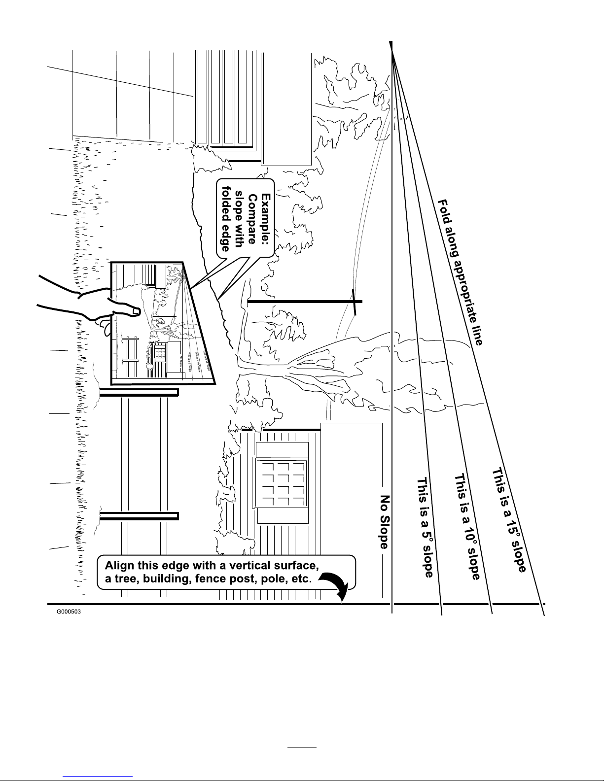
SlopeChart
7
Page 8
SafetyandInstructional
Decals
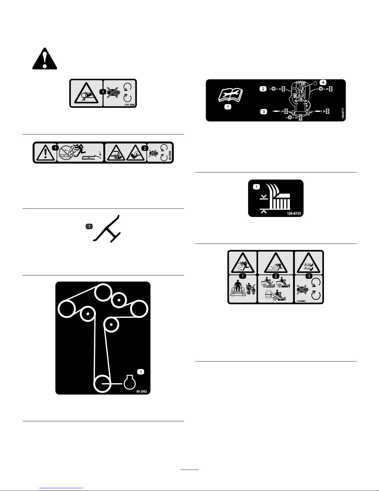
Safetydecalsandinstructionsareeasilyvisibletotheoperatorandarelocatednearanyareaof
potentialdanger.Replaceanydecalthatisdamagedorlost.
114-1606
1.Entanglementhazard,belt—keepallguardsinplace.
93-7009
1.Warning—don’toperatethemowerwiththedeectorupor
removed;keepthedeectorinplace.
2.Cutting/dismembermenthazardofhandorfoot,mower
blade—stayawayfrommovingparts.
Manufacturer’sMark
1.Indicatesthebladeisidentiedasapartfromtheoriginal
machinemanufacturer.
99-3943
1.Engine
106-8717
1.Readtheinstructionsbeforeservicingorperforming
maintenance.
2.Checktirepressureevery25operatinghours.
3.Greaseevery25operatinghours.
4.Engine
106-8743
1.Heightofcut
110-6691
1.Thrownobjecthazard—keepbystandersasafedistance
fromthemachine.
2.Thrownobjecthazard,mower—donotoperatethewithout
deectororgrasscollectionsysteminplace.
3.Cutting/dismembermentofhandorfoot—stayawayfrom
movingparts.
8
Page 9

112-9802
1.Height-of-cut
110-6654
1.Fast
5.Powertake-off(PTO),
Bladecontrolswitchon
somemodels
2.Continuousvariable
setting
6.Disengage
3.Slow
7.Engage
4.Choke
112-9750
1.Parkingbrake4.Neutral
2.Fast5.Reverse
3.Slow
112-9751
1.Parkingbrake4.Neutral
2.Fast5.Reverse
3.Slow
112-9840
1.ReadtheOperator’s
Manual.
3.Removetheignitionkey
andreadtheinstructions
beforeservicingor
performingmaintenance.
2.Heightofcut
110-6680
1.Bypasslever,engaged2.Bypasslever,disengaged
110-6690
1.Bypasslever,engaged2.Bypasslever,disengaged
9
Page 10
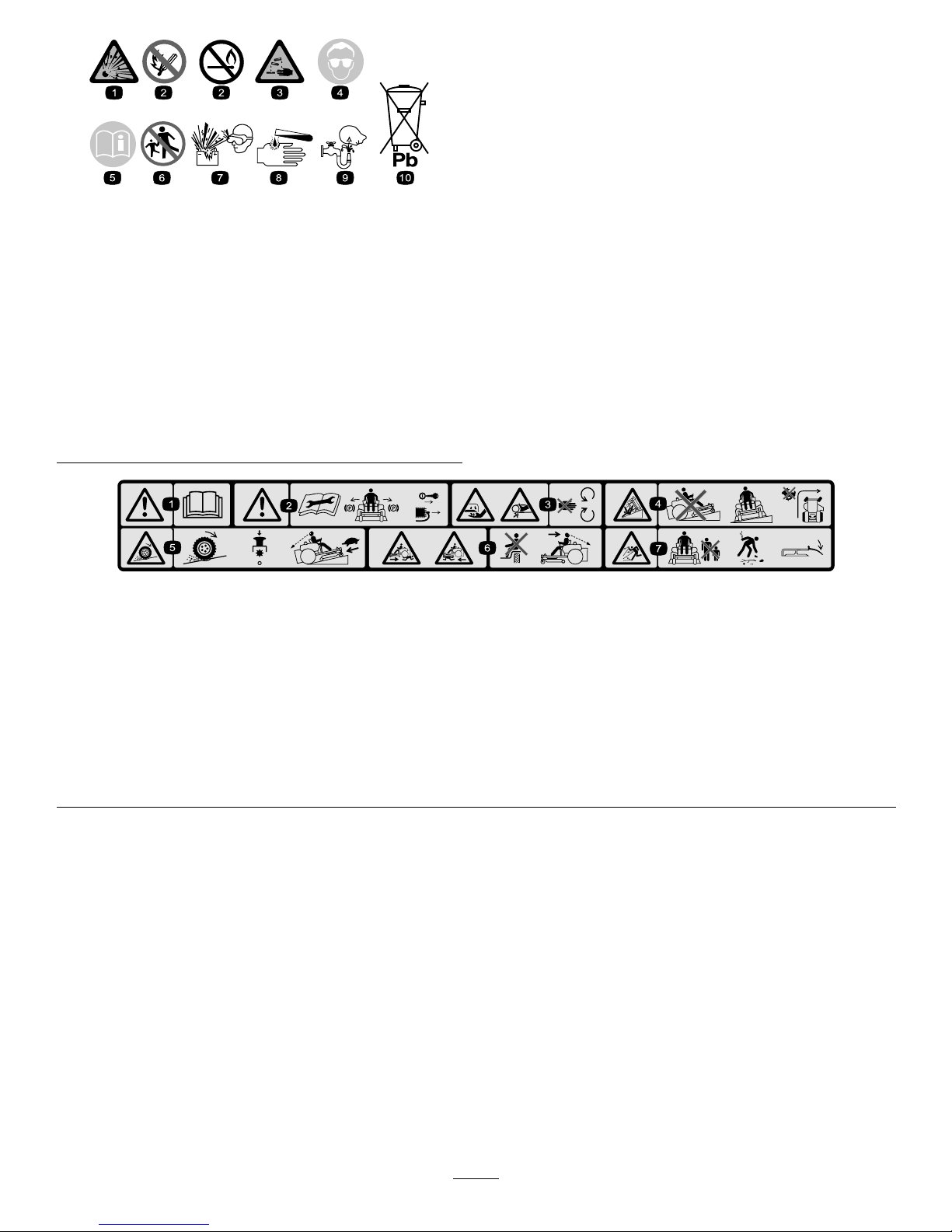
BatterySymbols
Someorallofthesesymbolsareonyourbattery
1.Explosionhazard
6.Keepbystandersasafe
distancefromthebattery.
2.Nore,opename,or
smoking.
7.Weareyeprotection;
explosivegasescan
causeblindnessandother
injuries
3.Causticliquid/chemical
burnhazard
8.Batteryacidcancause
blindnessorsevereburns.
4.Weareyeprotection9.Flusheyesimmediately
withwaterandgetmedical
helpfast.
5.ReadtheOperator’s
Manual.
10.Containslead;donot
discard.
1.
< 15∞
110-6825
1.
2.
3.
2.
110-6825
1.Warning—readtheOperator’sManual.
2.Warning—readtheinstructionsbeforeservicingorperformingmaintenance;movethemotioncontrolleverstothebrakeposition,
removetheignitionkeyanddisconnectthesparkplugwire.
3.Cutting/dismembermenthazard,mowerblade;entanglementhazard,belt—donotopenorremovesafetyshieldswhileengineis
running.
4.Tippinghazard—donotmowupanddownslopes,onlymowacrossslopeslessthan15degrees,avoidsuddenandsharp
turnswhileonslopes.
5.Lossoftraction/controlhazard,slopes—lossoftraction/controlonaslope,disengagethebladecontrolswitch(PTO),proceed
offtheslopeslowly.
6.Crushing/dismembermenthazardofbystanders,reversing;crushing/dismembermenthazardofbystanders—donotcarry
passengers,lookbehindanddownwhenreversing.
7.Thrownobjecthazard—keepbystandersasafedistancefromthemachine,pickupdebrisbeforeoperating,keepdeectorinplace.
10
Page 11
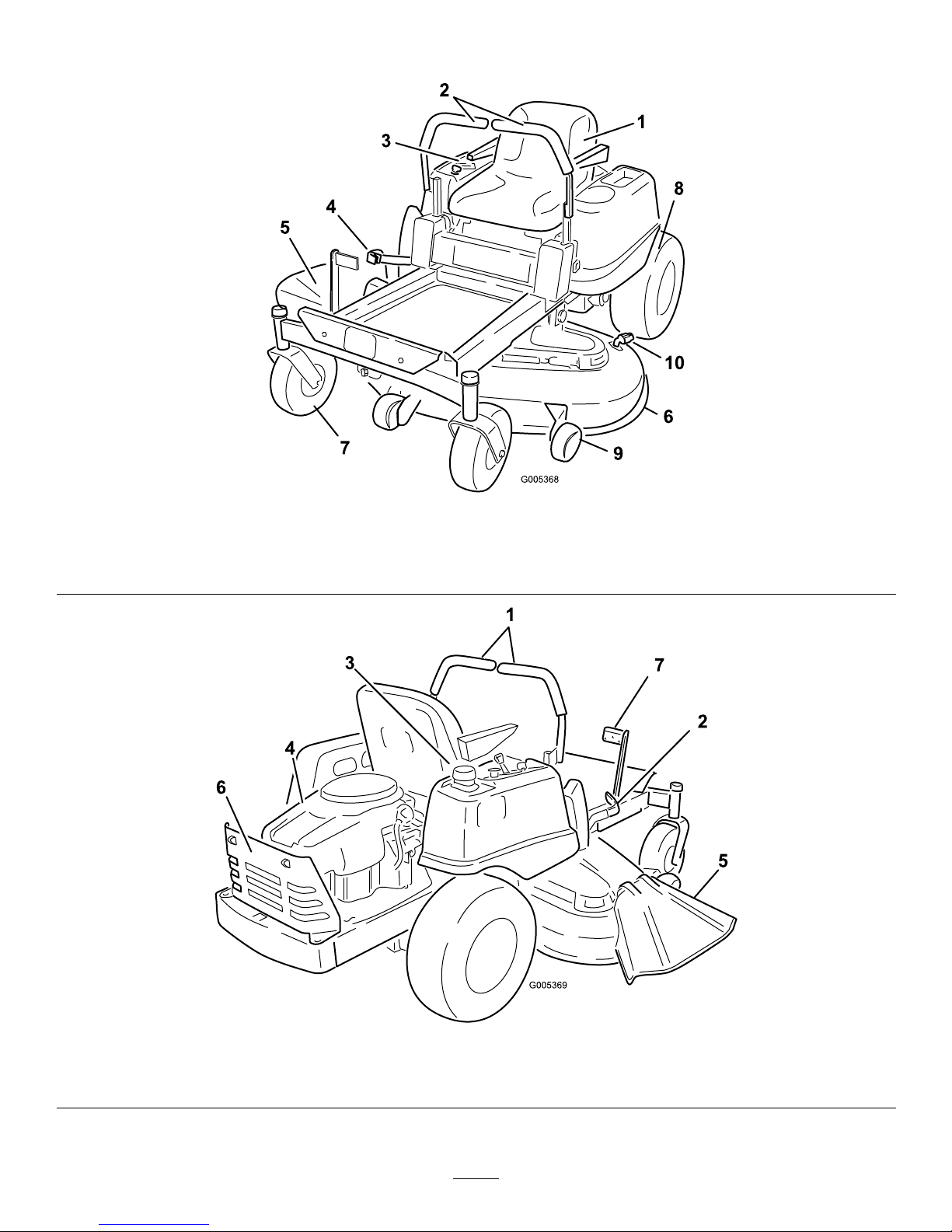
ProductOverview
Figure3
1.Operatorseat4.Heightofcutlever
7.Frontcasterwheel
10.Washouttting
2.Controllevers
5.Footrest8.Reardrivewheel
3.Controlpanel
6.Mowerdeck9.Anti-scalproller
Figure4
1.Motioncontrollevers
3.Gastankcap5.Deector
7.Footassistpedal
2.Heightofcutlever
4.Engine6.Engineguard
11
Page 12
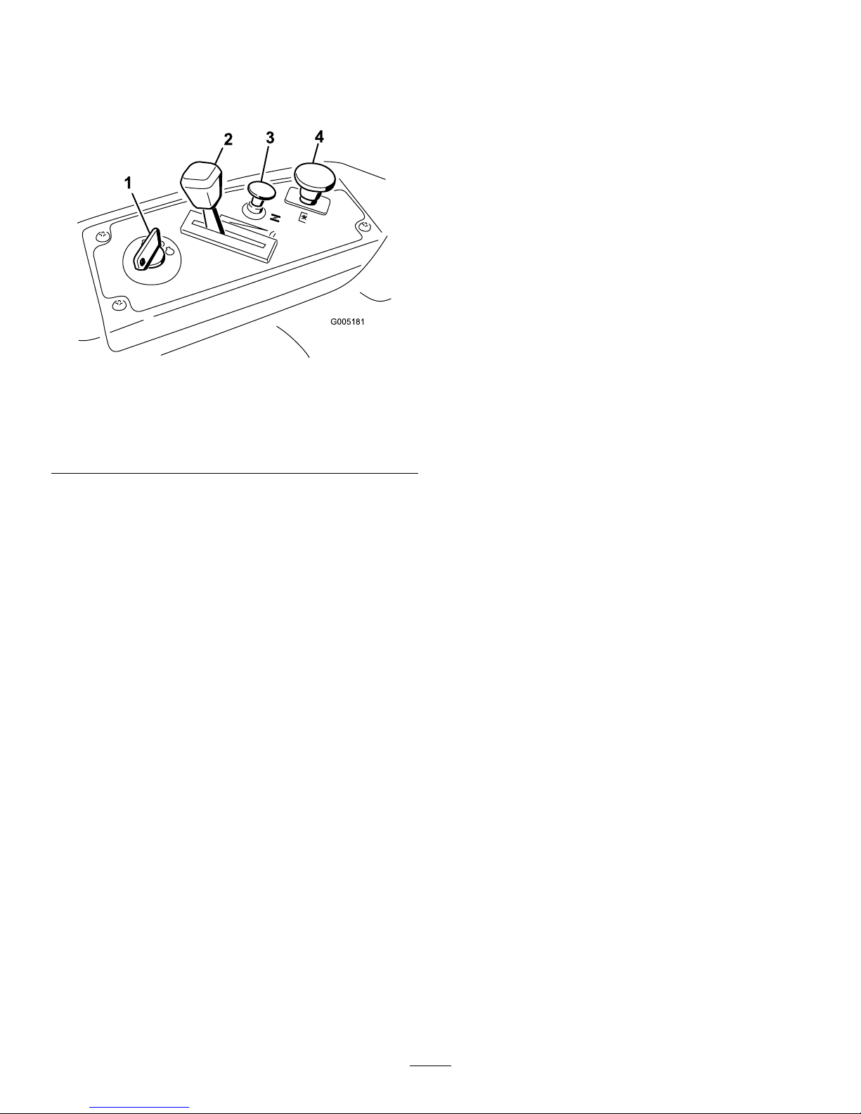
Controls
BecomefamiliarwithallofthecontrolsinFigure3,
Figure4,andFigure5beforeyoustarttheengineand
operatethemachine.
G005181
1
2
3
4
Figure5
ControlPanel
1.Ignitionswitch
3.Chokecontrol
2.Throttlecontrol4.Bladecontrolswitch
(powertake-off)
IgnitionSwitch
Theignitionswitchhasthreepositions,Off,Runand
Start.ThekeywillturntoStartandmovebackto
Runuponrelease.TuringthekeytotheOffposition
willstoptheengine;however,alwaysremovethekey
whenleavingthemachinetopreventtheenginefrom
accidentallystarting(Figure5).
ThrottleControl
Thethrottlecontrolstheenginespeedandithasa
continuousvariablesettingfromSlowtoFast(Figure5).
ChokeControl
PullupontheChokecontroluntilitstopstochokethe
engine(Figure5).PushdownontheChokecontrolfor
normalengineoperation
BladeControlSwitch(PowerTake-Off)
Thebladecontrolswitch,representedbyapower
take-off(PTO)symbol,engagesanddisengagespower
tothemowerblades(Figure5).
MotionControlLeversandParking
Brake
Themotioncontrolleversarespeedsensitivecontrols
ofindependentwheelmotors.Movingaleverforward
orbackwardturnsthewheelonthesamesideforward
orinreverse;wheelspeedisproportionaltotheamount
theleverismoved.Movingthecontrolleversoutward
fromthecenterpositionengagestheparkingbrakeand
allowstheoperatortoexitthemachine(Figure13).
Alwayspositionthemotioncontrolleversintothe
brakepositionwhenyoustopthemachineorleaveit
unattended.
Height-of-CutLever
Theheightofcutleverallowstheoperatortolower
andraisethedeckfromtheseatedposition.Whenthe
leverismovedup,towardtheoperatorthedeckisraised
fromthegroundandwhenmoveddown,awayfromthe
operatoritisloweredtowardtheground.Onlyadjustthe
heightofcutwhilemachineisnotmoving(Figure15).
FootAssistPedal
Thefootassistpedalallowstheoperatortosupportthe
weightofthedeckwiththeirlegduringadjustingthe
deckheightviatheheight-of-cutlever.
12
Page 13
Operation
Note:Determinetheleftandrightsidesofthe
machinefromthenormaloperatingposition.
ThinkSafetyFirst
Pleasecarefullyreadallofthesafetyinstructionsand
decalsinthesafetysection.Knowingthisinformation
couldhelpyou,yourfamily,petsorbystandersavoid
injury.
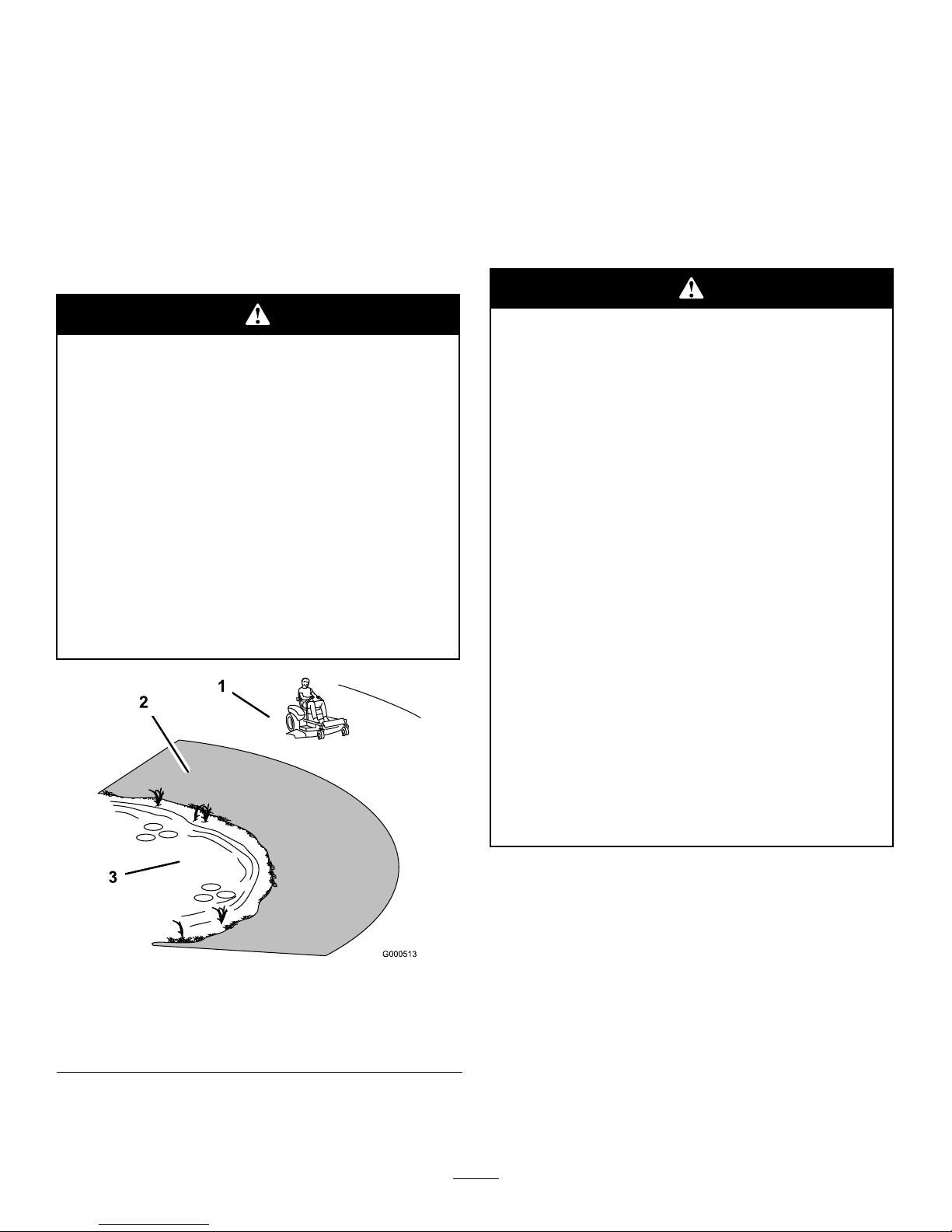
Mowingonwetgrassorsteepslopescancause
slidingandlossofcontrol.
Wheelsdroppingoveredgescancauserollovers,
whichmayresultinseriousinjury,deathor
drowning.
Toavoidlossofcontrolandpossibilityof
rollover:
•Donotmowneardrop-offsornearwater.
•Donotmowslopesgreaterthan15degrees.
•Reducespeedanduseextremecautionon
slopes.
•Avoidsuddenturnsorrapidspeedchanges.
Figure6
1.SafeZone-usetheTimeCutterhere
2.Usewalkbehindmowerand/orhandtrimmerneardrop-offs
andwater.
3.Water
RecommendedGasoline
UseUNLEADEDRegularGasolinesuitablefor
automotiveuse(87pumpoctaneminimum).Leaded
regulargasolinemaybeusedifunleadedregularisnot
available.
Important:Neverusemethanol,gasoline
containingmethanol,orgasoholcontainingmore
than10%ethanolbecausethefuelsystemcouldbe
damaged.Donotmixoilwithgasoline.
Incertainconditions,gasolineisextremely
ammableandhighlyexplosive.Areor
explosionfromgasolinecanburnyouand
othersandcandamageproperty.
•Fillthefueltankoutdoors,inanopenarea,
whentheengineiscold.Wipeupany
gasolinethatspills.
•Neverllthefueltankinsideanenclosed
trailer.
•Donotllthefueltankcompletelyfull.Add
gasolinetothefueltankuntilthebodyof
thetankisfullbutfueldoesnotlltheneck
ofthetank.Thisemptyspaceinthetank
allowsgasolinetoexpand.
•Neversmokewhenhandlinggasoline,and
stayawayfromanopenameorwhere
gasolinefumesmaybeignitedbyaspark.
•Storegasolineinanapprovedcontainerand
keepitoutofthereachofchildren.Never
buymorethana30-daysupplyofgasoline.
•Donotoperatewithoutentireexhaust
systeminplaceandinproperworking
condition.
13
Page 14

Incertainconditionsduringfueling,static
electricitycanbereleasedcausingaspark
whichcanignitethegasolinevapors.Are
orexplosionfromgasolinecanburnyouand
othersandcandamageproperty.
•Alwaysplacegasolinecontainersonthe
groundawayfromyourvehiclebeforelling.
•Donotllgasolinecontainersinsidea
vehicleoronatruckortrailerbedbecause
interiorcarpetsorplastictruckbedliners
mayinsulatethecontainerandslowtheloss
ofanystaticcharge.
•Whenpractical,removegas-powered
equipmentfromthetruckortrailerand
refueltheequipmentwithitswheelsonthe
ground.
•Ifthisisnotpossible,thenrefuelsuch
equipmentonatruckortrailerfroma
portablecontainer,ratherthanfroma
gasolinedispensernozzle.
•Ifagasolinedispensernozzlemustbeused,
keepthenozzleincontactwiththerimof
thefueltankorcontaineropeningatall
timesuntilfuelingiscomplete.
Gasolineisharmfulorfatalifswallowed.
Long-termexposuretovaporscancauseserious
injuryandillness.
•Avoidprolongedbreathingofvapors.
•Keepfaceawayfromnozzleandgastankor
conditioneropening.
•Keepgasawayfromeyesandskin.
UsingStabilizer/Conditioner
Useafuelstabilizer/conditionerinthemachineto
providethefollowingbenets:
•Keepsgasolinefreshduringstorageof30daysor
less.Forlongerstorageitisrecommendedthatthe
fueltankbedrained.
•Cleanstheenginewhileitruns
•Eliminatesgum-likevarnishbuildupinthefuel
system,whichcauseshardstarting
Addthecorrectamountofgasstabilizer/conditioner
tothegas.
Note:Afuelstabilizer/conditionerismosteffective
whenmixedwithfreshgasoline.Tominimizethe
chanceofvarnishdepositsinthefuelsystem,usefuel
stabilizeratalltimes.
Gasoline/Alcoholblends
Gasohol(upto10percentethylalcohol,90percent
unleadedgasolinebyvolume)isapprovedforfueluse
bytheenginemanufacturer.Othergasoline/alcohol
blendsarenotapproved.
Gasoline/Etherblends
MethylTertiaryButylEther(MTBE)andunleaded
gasolineblends(uptoamaximumof15percentMTBE
byvolume)areapprovedforfuelusebytheengine
manufacturer.Othergasoline/etherblendsarenot
approved.
FillingtheFuelTank
1.Shuttheengineoffandsetthemotioncontrolsto
theparkposition.Raisetheseatsothegastankis
visiblewhilefueling.
2.Cleanaroundthefueltankcapandremovethecap.
3.Addunleadedregulargasolineuntilthebodyofthe
tankisfullbutfueldoesnotlltheneckofthe
tank(Figure7).Thisspaceintheneckofthetank
allowsgasolinetoexpand.Donotllthefueltank
completelyfull.
4.Installthefueltankcapsecurely.Wipeupany
gasolinethatmayhavespilled.
14
Page 15

G005302
1
2
3
4
Figure7
1.Gastankbody
3.Filltohere,approximately
2.Gastankneck4.Gastankopening
CheckingtheEngineOilLevel
Beforeyoustarttheengineandusethemachine,check
theoillevelintheenginecrankcase;refertoChecking
theOilLevelinEngineMaintenance,page24.
StartingandStoppingthe
Engine
StartingtheEngine
1.Sitdownontheseatandmovethemotioncontrols
outwardtotheparkposition.
2.Disengagethebladesbymovingthebladecontrol
switchtoOff(Figure8).
Figure8
1.Controlpanel2.Bladecontrolswitch—Off
position
3.PullupontheChokecontrolbeforestartingacold
engine(Figure10).
Note:Awarmorhotenginemaynotrequire
choking.
G005183
1
2
2
1
2
2
3
4
5
6
Figure9
1.Controlpanel4.Continuousvariable
setting
2.Throttle
5.Slow
3.Fast
6.Chokecontrol
4.TurntheignitionkeytoStarttoenergizethestarter.
Whentheenginestarts,releasethekey(Figure10).
Important:Donotengagethestarterformore
than10secondsatatime.Iftheenginefails
tostart,allowa60secondcool-downperiod
betweenattempts.Failuretofollowthese
instructionscanburnoutthestartermotor.
15
Page 16

G005184
1
2
3
4
5
6
1
2
3
4
5
6
7
Figure10
1.Controlpanel
5.Run
2.Ignitionkey—runposition
6.Start
3.Ignitionkey—startposition
7.Chokecontrol
4.Off
5.Aftertheenginestarts,pushdownontheChoke
control(Figure10).Iftheenginestallsorhesitates,
pullupontheChokecontrolandlettheenginerun
forafewseconds.ThenpushdownontheChoke
controlandmovethethrottlelevertothedesired
setting.Repeatthisasrequired.
OperatingtheBlades
Thebladecontrolswitch,representedbyapower
take-off(PTO)symbol,engagesanddisengagespower
tothemowerblades.Thisswitchcontrolspowertoany
attachmentsthatdrawpowerfromtheengine,including
themowerdeckandcuttingblades.
EngagingtheBlades
1.Releasepressureonthemotioncontrolleversand
placethemachineinneutral.
2.MovethethrottletotheFastposition.
Note:Alwaysengagethebladeswiththethrottle
intheFastposition.
3.PulloutonthebladecontrolswitchtoOnto
engagetheblades(Figure11).
G005185
121
2
Figure11
1.Controlpanel2.Bladecontrolswitch—On
position
DisengagingtheBlades
PushthebladecontrolswitchtoOfftodisengagethe
blades(Figure12).
Figure12
1.Controlpanel2.Bladecontrolswitch—Off
StoppingtheEngine
1.Disengagethebladesbymovingthebladecontrol
switchtoOff(Figure8).
2.MovethethrottlelevertobetweenFastandhalf
throttle(Figure10).
3.TurntheignitionkeytoOff(Figure9).
4.Pullthewireoffofthesparkplug(s)toprevent
thepossibilityofsomeoneaccidentallystartingthe
machinebeforetransportingorstoringthemachine.
16
Page 17

TheSafetyInterlockSystem
Ifsafetyinterlockswitchesaredisconnected
ordamagedthemachinecouldoperate
unexpectedlycausingpersonalinjury.
•Donottamperwiththeinterlockswitches.
•Checktheoperationoftheinterlock
switchesdailyandreplaceanydamaged
switchesbeforeoperatingthemachine.
UnderstandingtheSafetyInterlock
System
Thesafetyinterlocksystemisdesignedtopreventthe
enginefromstartingunless:
•Thebladesaredisengaged.
•Themotioncontrolleversareintheparkposition.
Thesafetyinterlocksystemalsoisdesignedtostop
theenginewhenthecontrolleversareoutofthepark
positionandyourisefromtheseatwhentheblades
areengaged.
TestingtheSafetyInterlockSystem
Testthesafetyinterlocksystembeforeyouusethe
machineeachtime.Ifthesafetysystemdoesnot
operateasdescribedbelow ,haveanAuthorizedService
Dealerrepairthesafetysystemimmediately .
1.Whilesittingontheseat,withthecontrolleversin
parkposition,andmovethebladecontrolswitch
toOn.Trystartingtheengine;theengineshould
notcrank.
2.Whilesittingontheseat,movethebladecontrol
switchtoOff.Moveeithermotioncontrollever
tothecenter,unlockedposition.Trystartingthe
engine;theengineshouldnotcrank.Repeatwith
theothermotioncontrollever.
3.Whilesittingontheseat,movethebladecontrol
switchtoOff,andlockthemotioncontrolleversin
theparkposition.Starttheengine.Whiletheengine
isrunning,engagethebladecontrolswitch,andrise
slightlyfromtheseat;theengineshouldstop.
4.Whilesittingontheseat,movethebladecontrol
switchtoOff,andlockthemotioncontrollevers
intheparkposition.Starttheengine.Whilethe
engineisrunning,movethemotioncontrollevers
tothecenter,unlockedposition,engagetheblade
controlswitch,andriseslightlyfromtheseat;the
engineshouldstop.
DrivingForwardorBackward
Thethrottlecontrolregulatestheenginespeedas
measuredinrpm(revolutionsperminute).Place
thethrottlecontrolintheFastpositionforbest
performance.Alwaysoperateinthefullthrottle
position.
Themachinecanspinveryrapidly .The
operatormaylosecontrolofthemachine
andcausepersonalinjuryordamagetothe
machine.
•Usecautionwhenmakingturns.
•Slowthemachinedownbeforemaking
sharpturns.
Forward
1.Movetheleverstothecenter,unlockedposition.
2.Togoforward,slowlypushthemotioncontrol
leversforward(Figure13).
Figure13
1.Brakeposition3.Forward
2.Centerunlockposition
4.Backward
Togostraight,applyequalpressuretobothmotion
controllevers(Figure13).
17
Page 18

Toturn,releasepressureonthemotioncontrollever
towardthedirectionyouwanttoturn(Figure13).
Thefartheryoumovethemotioncontrolleversin
eitherdirection,thefasterthemachinewillmovein
thatdirection.
Tostop,pullthemotioncontrolleverstoneutral.
Backward
1.Movetheleverstothecenter,unlockedposition.
2.Togobackward,slowlypullthemotioncontrol
leversrearward(Figure13).
Togostraight,applyequalpressuretobothmotion
controllevers(Figure13).
Toturn,releasethepressureonthemotion
controllevertowardthedirectionyouwanttoturn
(Figure13).
Tostop,pushthemotioncontrolleverstoneutral.
StoppingtheMachine
Tostopthemachine,movethemotioncontrolleversto
neutralandoutwardtotheparkposition,disengagethe
bladecontrolswitch,ensurethethrottleisinthefast
position,andturntheignitionkeytooff.Rememberto
removethekeyfromtheignitionswitch.
Childrenorbystandersmaybeinjuredifthey
moveorattempttooperatethemowerwhileit
isunattended.
Alwaysremovetheignitionkeyandmovethe
motioncontrolleversoutwardtothepark
positionwhenleavingthemachineunattended,
evenifjustforafewminutes.
AdjustingtheHeightofCut
1.Entertheoperator’sposition.Placeafootonthe
footassistpedalandapplypressure.
2.Whilemaintainingpressureonthepedal,pull
inwardandupontheheight-of-cutleverandmove
ittothedesiredposition.
Figure14
3.Raisetheheight-of-cutlevertothetransport
position,cuttingheightposition4.5(alsothe
4-1/2inch[115mm])(Figure15).
18
Page 19

4-1/2in(1 15mm)
4in.(102mm)
3-1/2in(89mm)
3in(76mm)
2-1/2in(64mm)
2in(51mm)
1-1/2in(38mm)
4-1/2in(1 15mm)
4in(102mm)
3-1/2in(89mm)
3in(76mm)
2-1/2in(64mm)
2in(51mm)
1-1/2in(38mm)
G005312
4.5
1
2
4
3.5
3
2.5
2
1.5
Figure15
1.Height-of-cutlever2.Height-of-cutpositions
PositioningtheSeat
Theseatcanmoveforwardandbackward.Positionthe
seatwhereyouhavethebestcontrolofthemachine
andaremostcomfortable.
1.Raisetheseatandloosentheadjustmentknobjust
enoughthatseatcanmove(Figure16).
G005061
1
Figure16
1.Adjustmentknob
2.Movetheseattothedesiredpositionandtighten
theknob.
AdjustingtheMotionControl
Levers
AdjustingtheHeight
Themotioncontrolleverscanbeadjustedhigheror
lowerformaximumoperatorcomfort.
1.Removethe2boltsholdingthecontrollevertothe
controlarmshaft(Figure17).
2.Movethecontrollevertothenextsetofholes.
Securetheleverwiththe2bolts(Figure17).
G005062
1
2
3
4
Figure17
1.Controlarmshaft3.Slotted,upperhole
2.Controllever
4.Bolt
3.Repeattheadjustmentfortheoppositecontrol
lever.
AdjustingtheTilt
Themotioncontrolleverscanbetiltedforeoraftfor
maximumoperatorcomfort.
1.Loosentheupperboltholdingthecontrolleverto
thecontrolarmshaft.
2.Loosenthelowerboltjustenoughtopivotthe
controlleverforeoraft(Figure17).Tightenboth
boltstosecurethecontrolinthenewposition.
3.Repeattheadjustmentfortheoppositecontrol
lever.
PushingtheMachinebyHand
Important:Alwayspushthemachinebyhand.
Nevertowthemachinebecausedamagemay
occur.
19
Page 20

ToPushtheMachine
1.Parkthemachineonalevelsurfaceanddisengage
thebladecontrolswitch.
2.Movethemotioncontrolleversoutwardtopark
position,stoptheengine,removethekey,andwait
forallmovingpartstostopbeforeleavingthe
operatingposition.
3.Locatethebypassleversattherearofthemachine,
ontheleftandrightsideoftheframe.
4.Movethebypassleversrearwardandthendown
tolocktheminplaceasshowninFigure18to
disengagethewheelmotors.Repeatthisoneach
sideofthemachine.
5.Movethemotioncontrolleversinwardtodisengage
theparkingbrake.
Themachineisnowabletobepushedbyhand.
G005063
1
2
3
Figure18
Rightsideshown
1.Bypassleverlocation
3.Leverpositionfor
operatingthemachine
2.Leverpositionforpushing
themachine
ToOperatetheMachine
Movethebypassleversupwardandpushthemforward,
tothemiddleofthehorizontalslot(Figure18)to
engagethewheelmotors.
Note:Donotmovethebypassleversfullyforward
intotheverticalcutoutoftheslot.Themachinewill
notdriveunlessthewheelmotorsareengaged,withthe
bypassleversinthemiddleofthehorizontalslot.
SideDischarge
Themowerhasahingedgrassdeectorthatdisperses
clippingstothesideanddowntowardtheturf.
Withoutthegrassdeector,dischargecover,
orcompletegrasscatcherassemblymounted
inplace,youandothersareexposedtoblade
contactandthrowndebris.Contactwith
rotatingmowerblade(s)andthrowndebriswill
causeinjuryordeath.
•Neverremovethegrassdeectorfrom
themowerbecausethegrassdeector
routesmaterialdowntowardtheturf.Ifthe
grassdeectoriseverdamaged,replaceit
immediately.
•Neverputyourhandsorfeetunderthe
mower.
•Nevertrytocleardischargeareaormower
bladesunlessyoumovethebladecontrol
switchtoOffandrotatetheignitionkeyto
Off.Alsoremovethekeyandpullthewire
offthesparkplug(s).
OperatingTips
FastThrottleSetting
Forbestmowingandmaximumaircirculation,operate
theengineattheFastposition.Airisrequiredto
thoroughlycutgrassclippings,sodonotsetthe
height-of-cutsolowastototallysurroundthemower
byuncutgrass.Alwaystrytohaveonesideofthe
mowerfreefromuncutgrass,whichallowsairtobe
drawnintothemower.
CuttingaLawnfortheFirstTime
Cutgrassslightlylongerthannormaltoensurethatthe
cuttingheightofthemowerdoesnotscalpanyuneven
ground.However,thecuttingheightusedinthepastis
generallythebestonetouse.Whencuttinggrasslonger
thansixinchestall,youmaywanttocutthelawntwice
toensureanacceptablequalityofcut.
Cut1/3oftheGrassBlade
Itisbesttocutonlyabout1/3ofthegrassblade.
Cuttingmorethanthatisnotrecommendedunless
grassissparse,oritislatefallwhengrassgrowsmore
slowly.
20
Page 21

MowingDirection
Alternatemowingdirectiontokeepthegrassstanding
straight.Thisalsohelpsdisperseclippingswhich
enhancesdecompositionandfertilization.
MowatCorrectIntervals
Normally,moweveryfourdays.Butremember,
grassgrowsatdifferentratesatdifferenttimes.So
tomaintainthesamecuttingheight,whichisagood
practice,mowmoreofteninearlyspring.Asthegrass
growthrateslowsinmidsummer,mowlessfrequently.
Ifyoucannotmowforanextendedperiod,rstmow
atahighcuttingheight;thenmowagaintwodayslater
atalowerheightsetting.
CuttingSpeed
Toimprovecutquality,useaslowergroundspeed.
AvoidCuttingTooLow
Ifthecuttingwidthofthemoweriswiderthanthe
moweryoupreviouslyused,raisethecuttingheightto
ensurethatuneventurfisnotcuttooshort.
LongGrass
Ifthegrassiseverallowedtogrowslightlylongerthan
normal,orifitcontainsahighdegreeofmoisture,raise
thecuttingheighthigherthanusualandcutthegrassat
thissetting.Thencutthegrassagainusingthelower,
normalsetting.
WhenStopping
Ifthemachine’sforwardmotionmustbestoppedwhile
mowing,aclumpofgrassclippingsmaydropontoyour
lawn.T oavoidthis,moveontoapreviouslycutarea
withthebladesengaged.
KeeptheUndersideoftheMower
Clean
Cleanclippingsanddirtfromtheundersideofthe
moweraftereachuse.Ifgrassanddirtbuildupinside
themower,cuttingqualitywilleventuallybecome
unsatisfactory.
BladeMaintenance
Maintainasharpbladethroughoutthecuttingseason
becauseasharpbladecutscleanlywithouttearingor
shreddingthegrassblades.Tearingandshreddingturns
grassbrownattheedges,whichslowsgrowthand
increasesthechanceofdisease.Checkthecutterblades
dailyforsharpness,andforanywearordamage.File
downanynicksandsharpenthebladesasnecessary.If
abladeisdamagedorworn,replaceitimmediatelywith
agenuineTororeplacementblade.
21
Page 22

Maintenance
Note:Determinetheleftandrightsidesofthemachinefromthenormaloperatingposition.
RecommendedMaintenanceSchedule(s)
MaintenanceService
Interval
MaintenanceProcedure
Beforeeachuseordaily
•Checkthesafetyinterlocksystem.
•Checktheaircleanerfordirty,looseordamagedparts.
•Checktheengineoillevel.
•Checkairintakeandcoolingareas,cleanasnecessary.
•Checkthecuttingblades.
•Cleanthemowerhousing.
Every25hours
•Greasealllubricationpoints.
•Checktirepressure.
•Checkthebeltsforwear/cracks.
Every50hours
•Servicethepaperelement.(moreoftenunderextremelydusty,dirtyconditions)
Every100hours
•Replacethepaperelement.(moreoftenunderextremelydusty,dirtyconditions)
•Changetheengineoilandlter.
•Cleantheblowerhousing(moreoftenunderextremelydusty,dirtyconditions).
•Replacethefuellter.
Every200hours
•Checksparkplug(s)conditionandgap.
Every500hours
•Replacethesparkplug(s).
Beforestorage
•Chargethebatteryanddisconnectbatterycables.
•Performallmaintenanceprocedureslistedabovebeforestorage.
•Paintanychippedsurfaces.
Important:Refertoyourengineoperator’smanualforadditionalmaintenanceprocedures.
Ifyouleavethekeyintheignitionswitch,someonecouldaccidentlystarttheengineandseriously
injureyouorotherbystanders.
Removethekeyfromtheignitionanddisconnectthewirefromthesparkplugbeforeyoudoany
maintenance.Setthewireasidesothatitdoesnotaccidentallycontactthesparkplug.
22
Page 23

Premaintenance
Procedures
RaisingtheSeat
Makesurethemotioncontrolleversarelockedinthe
parkposition.Lifttheseatforwardandlowerittothe
oorboard.
Thefollowingcomponentscanbeaccessedbyraising
theseat:
•Serialplate
•Servicedecal
•Seatadjustmentknob
•Fuellter
•Fuses
•Batterycables
AccessingtheBattery
1.Raisetheseat.
2.RemovetheTORX
®
headfasteners(25)securing
theleftcovertotheframeasshowninFigure19.
2
3
G005065
1
2
2
2
3
Figure19
1.Leftcover
3.Battery
2.Torxheadfasteners(25)
3.Lifttheplasticcoverawayfromthemachine.Retain
allfasteners.
Replacethecoverandsecureittotheframeusingthe
fastenersremovedpreviously.
Lubrication
GreasingtheBearings
ServiceInterval:Every25hours—Greaseall
lubricationpoints.
GreaseType:No.2GeneralPurposeLithiumBase
Grease
1.Parkthemachineonalevelsurfaceanddisengage
thebladecontrolswitch.
2.Movethemotioncontrolleversoutwardtothe
parkposition,stoptheengine,removethekey,and
waitforallmovingpartstostopbeforeleavingthe
operatingposition.
3.Cleanthegreasettings(Figure20andFigure21)
witharag.Makesuretoscrapeanypaintoffofthe
frontofthetting(s).
G005066
1
Figure20
1.Frontcastertire
Figure21
Locatedontheseatpanunderside
1.Readtheinstructions
beforeservicingor
performingmaintenance.
3.Greaseevery25operating
hours.
2.Checktirepressureevery
25operatinghours.
4.Engine
23
Page 24

4.Connectagreaseguntoeachtting(Figure20and
Figure21).Pumpgreaseintothettingsuntilgrease
beginstooozeoutofthebearings.
5.Wipeupanyexcessgrease.
EngineMaintenance
ServicingtheAirCleaner
ServiceInterval:Beforeeachuseordaily—Checkthe
aircleanerfordirty,looseordamaged
parts.
Thisengineisequippedwithareplaceable,highdensity
paperaircleanerelement.Checktheaircleanerdailyor
beforestartingtheengine.Checkforabuildupofdirt
anddebrisaroundtheaircleanersystem.Keepthisarea
clean.Alsocheckforlooseordamagedcomponents.
Replaceallbentordamagedaircleanercomponents.
Note:Operatingtheenginewithlooseordamagedair
cleanercomponentscouldallowunlteredairintothe
enginecausingprematurewearandfailure.
Note:Servicetheaircleanermoreoftenunder
extremelydusty,dirtyconditions.
24
Page 25

G005187
1
2
3
4
Figure22
1.Aircleanercover3.Paperelement
2.Aircleanerlatch4.Aircleanerbase
ServicingPaperElement
ServiceInterval:Every50hours—Servicethepaper
element.(moreoftenunderextremely
dusty,dirtyconditions)
Every100hours—Replacethepaper
element.(moreoftenunderextremely
dusty,dirtyconditions)
1.Opentheaircleanercoverdoorontheblower
housingtoaccesstheaircleanerelement(Figure22).
2.Unhookthelatchandremovetheaircleanerelement
(Figure22).
3.Gentlytapthepaperelementtodislodgedirt.Do
notwashthepaperelementorusepressurized
air,asthiswilldamagetheelement.Replaceadirty,
bent,ordamagedelement.Handlethenewelement
carefully;donotuseifthesealingsurfacesarebent
ordamaged.
4.Cleantheaircleanerbaseasrequiredandcheck
condition.
5.Installthepaperelementontotheaircleanerbase.
Securewiththelatch.
6.Closetheaircleanercoverdoor.
ServicingtheEngineOil
OilType:Detergentoil(APIserviceSG,SH,SJ,or
higher)
CrankcaseCapacity:1.7qt(1.6l)whenthelteris
changed
Viscosity:Seethetablebelow .
Figure23
CheckingtheOilLevel
ServiceInterval:Beforeeachuseordaily—Checkthe
engineoillevel.
1.Parkthemachineonalevelsurface,disengagethe
bladecontrolswitch,stoptheengine,andremove
thekey .
2.Makesuretheengineisstopped,level,andiscoolso
theoilhashadtimetodrainintothesump.
3.Tokeepdirt,grassclippings,etc.,outoftheengine,
cleantheareaaroundtheoilllcap/dipstickbefore
removingit.
4.Unscrewandremovethedipstick;wipeoiloff
(Figure24).Reinsertthedipstickintothetubeand
restthecaponthetube.Donotscrewthecaponto
thetube.
25
Page 26

ADD FULL
G005188
1
2
3
4
Figure24
1.Oildipstick3.Oillevel—Fullmark
2.Fillertube
4.Oillevel—Addmark
5.Pullthedipstickoutandchecktheoillevel.
(Figure24).
Theoillevelshouldbeupto,butnotover,the
“FULL”or“F”markonthedipstick
6.Ifthelevelislow ,addoilofthepropertype,uptothe
“FULL”or“F”markonthedipstick.Alwayscheck
thelevelwiththedipstickbeforeaddingmoreoil.
Note:Topreventextensiveenginewearordamage,
alwaysmaintaintheproperoillevelinthecrankcase.
Neveroperatetheenginewiththeoillevelbelowthe
“ADD”or“L”markorabovethe“FULL”or“F”
markonthedipstick.
7.Removedipstickandcheckoillevel.Thelevelshould
bebetweenthe“FullorF”and“ AddorL”marks.If
low,addoilofthepropertypeuptothefullmark.
Reinstalloilllcap/dipstickandscrewtight.
ChangingtheOilandtheFilter
ServiceInterval:Every100hours—Changetheengine
oilandlter.
RellwithserviceclassSG,SH,SJorhigheroilas
speciedinthe“ViscosityGrades”table.
Changetheoilandlterwhiletheengineisstillwarm.
Theoilwillowmorefreelyandcarryawaymore
impurities.Makesuretheengineislevelwhenlling,
checking,orchangingtheoil.
Changetheoilandoillterasfollows:
1.Starttheengineandletitrununtilwarm.This
warmstheoilsoitdrainsbetter.
2.Parkthemachinesothatthedrainsideisslightly
lowerthantheoppositesidetoassuretheoildrains
completely.
3.Disengagethebladecontrolswitchandmovethe
motioncontrolsoutwardtotheparkposition.
4.Stoptheengine,removethekey,andwaitforall
movingpartstostopbeforeleavingtheoperating
position.
5.Locatetheoildrainhoseontheleftsideofthe
engine.Thedrainplugisattachedtoadrainhose
routedthroughadrainholeinthemachineframe
(Figure25).Cleantheareaaroundtheoildrainplug
capandtheoildrainhose.
6.Placeapanunderneathmachinedirectlybelowthe
oildrainhoseasshowninFigure25.
G005189
1
2
4
3
Figure25
1.Oildrainhose
3.Pan
2.Oildrainplugcap4.Machineframehole
7.Usingtwowrenches(onetoholdtheoildrainhose
andonetoloosentheplug),removetheoildrain
plug(Figure25).
8.Removetheoilllcap/dipstick(Figure24).
9.Besuretoallowampletimeforcompletedrainage.
10.Locatetheoillterontherightsideoftheengine.
Removetheoldlterandwipeoffthelteradapter
withacleancloth(Figure26).
26
Page 27

G005298
1
2
Figure26
1.Oillter
2.Adapter
11.Applyathinlmofcleanoiltotherubbergasketon
thenewlter.
12.Installthereplacementoilltertotheadapter.
Turntheoillterclockwiseuntiltherubbergasket
contactsthepad,thentightenthelteranadditional
3/4to1turn(Figure26).Wipeupanyexcessoil
ontheframe.
13.Whenoilhasdrainedcompletely,installtheoildrain
plug.Tightentheplugto14N⋅m(125in-lb)torque.
Wipeupanyexcessoil(Figure25).
Note:Disposeoftheusedoilatarecyclingcenter.
14.Slowlypourapproximately80%ofthespeciedoil
intothellertube(Figure24).
15.Installtheoilllcap/dipstick(Figure24).
16.Checktheoillevel(Figure24);refertoChecking
theOilLevel.
17.Slowlyaddadditionaloiltobringittothefullmark.
18.Installtheoilllcap/dipstickandscrewtight
(Figure24).
ServicingtheSparkPlug
ServiceInterval:Every200hours—Checkspark
plug(s)conditionandgap.
Every500hours—Replacethespark
plug(s).
ThesparkplugisRFIcompliant.Equivalentalternate
brandplugscanalsobeused.Sparkplugreplacementis
recommendedat500hours.
Type:ChampionXC12YC(orequivalent)
AirGap:0.030inch(0.76mm)
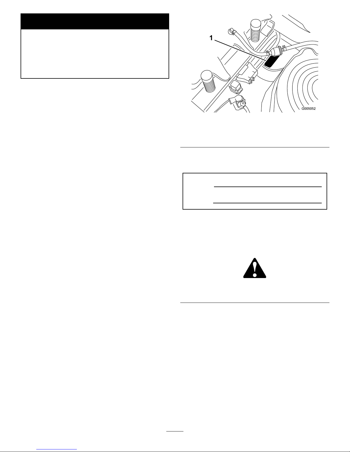
RemovingtheSparkPlug
1.Disengagethebladecontrolswitch,movethe
motioncontrolsoutwardtotheparkposition,stop
theengine,andremovethekey.
2.Beforeremovingthesparkplug(s),cleanthearea
aroundthebaseoftheplugtokeepdirtanddebris
outoftheengine.
Pullthewireoffofthesparkplug(s)(Figure27).
3.Cleanaroundthesparkplug(s)topreventdirt
fromfallingintotheengineandpotentiallycausing
damage.Removethesparkplug(s)andmetalwasher.
Figure27
1.Sparkplugandwirelocations
CheckingtheSparkPlug
1.Lookatthecenterofthesparkplug(Figure28).
Ifyouseelightbrownorgrayontheinsulator,the
engineisoperatingproperly .Ablackcoatingonthe
insulatorusuallymeanstheaircleanerisdirty.
Important:Nevercleanthesparkplug.Always
replacethesparkplugwhenithasablack
coating,wornelectrodes,anoilylm,orcracks.
2.Checkthegapbetweenthecenterandsideelectrodes
(Figure28).Bendthesideelectrode(Figure28)if
thegapisnotcorrect.
27
Page 28

Figure28
1.Centerelectrodeinsulator3.Airgap(nottoscale)
2.Sideelectrode
InstallingtheSparkPlug
1.Installthesparkplug.Makesurethattheairgapis
setcorrectly.
2.Tightenthesparkplugto18-22ft-lb(25-29N⋅m).
3.Pushthewireontothesparkplug(Figure27).
CleaningtheBlowerHousing
Toensurepropercooling,makesurethegrassscreen,
coolingns,andotherexternalsurfacesoftheengine
arekeptcleanatalltimes.
Annuallyorevery100hoursofoperation(moreoften
underextremelydusty ,dirtyconditions),removethe
blowerhousingandanyothercoolingshrouds.Clean
thecoolingnsandexternalsurfacesasnecessary.Make
surethecoolingshroudsarereinstalled.
Important:Operatingtheenginewithablocked
grassscreen,dirtyorpluggedcoolingns,and/or
coolingshroudsremoved,willcauseenginedamage
duetooverheating.
FuelSystem
Maintenance
Incertainconditions,gasolineisextremely
ammableandhighlyexplosive.Areor
explosionfromgasolinecanburnyouand
othersandcandamageproperty.
•Performanyfuelrelatedmaintenancewhen
theengineiscold.Dothisoutdoorsinan
openarea.Wipeupanygasolinethatspills.
•Neversmokewhendraininggasoline,and
stayawayfromanopenameorwherea
sparkmayignitethegasolinefumes.
ReplacingtheFuelFilter
ServiceInterval:Every100hours—Replacethefuel
lter.
Neverinstalladirtylterifitisremovedfromthefuel
line.
1.Parkthemachineonalevelsurfaceanddisengage
thebladecontrolswitch.
2.Movethemotioncontrolleversoutwardtothe
parkposition,stoptheengine,removethekey,and
waitforallmovingpartstostopbeforeleavingthe
operatingposition.
3.Raisetheseatandlocatethefuellinecomingfrom
thefueltankbelow .Thefuellterisinthefuelline
betweenthetankandengine.
28
Page 29

G005071
212
3
4
6
5
Figure29
1.Fuellinefromtank
4.Fuellinetoengine
2.Hoseclamp5.Flowdirectionarrow
3.Filter6.Fueltank
4.Squeezetheendsofthehoseclampstogetherand
slidethemawayfromthelter(Figure29).
5.Removethelterfromthefuellines.
6.Installanewlterwiththeowdirectionarrow
comingfromthefueltankandpointingtothe
engine.Movethehoseclampsclosetothelter
(Figure29)tosecureitinplace.
ElectricalSystem
Maintenance
Warning
CALIFORNIA
Proposition65Warning
Batteryposts,terminals,andrelated
accessoriescontainleadandleadcompounds,
chemicalsknowntotheStateofCalifornia
tocausecancerandreproductiveharm.
Washhandsafterhandling.
ChargingtheBattery
RemovingtheBattery
Batteryterminalsormetaltoolscouldshort
againstmetalmachinecomponentscausing
sparks.Sparkscancausethebatterygassesto
explode,resultinginpersonalinjury.
•Whenremovingorinstallingthebattery,do
notallowthebatteryterminalstotouchany
metalpartsofthemachine.
•Donotallowmetaltoolstoshortbetween
thebatteryterminalsandmetalpartsofthe
machine.
1.Parkthemachineonalevelsurfaceanddisengage
thebladecontrolswitch.
2.Movethemotioncontrolleversoutwardtothe
parkposition,stoptheengine,removethekey,and
waitforallmovingpartstostopbeforeleavingthe
operatingposition.
3.Removetheleftsideconsoletoaccessthe
battery.RefertheAccessingtheBatteryprocedurein
PremaintenanceProcedures,page23forinstructions.
4.Disconnectthenegative(black)groundcablefrom
thebatterypost(Figure30).Retainallfasteners.
29
Page 30

Incorrectbatterycableroutingcoulddamage
themachineandcablescausingsparks.Sparks
cancausethebatterygassestoexplode,
resultinginpersonalinjury.
•Alwaysdisconnectthenegative(black)
batterycablebeforedisconnectingthe
positive(red)cable.
•Alwaysconnectthepositive(red)battery
cablebeforeconnectingthenegative(black)
cable.
5.Slidetherubbercoverupthepositive(red)cable.
Disconnectthepositive(red)cablefromthebattery
post(Figure30).Retainallfasteners.
6.Removethebatteryhold-down(Figure30)andlift
thebatteryfromthebatterytray.
G005072
1
2
3
4
5
6
7
Figure30
1.Battery5.Negativebatterypost
2.Positivebatterypost6.Wingnut,washer,andbolt
3.Bolt,washer ,andnut7.Batteryhold-down
4.Terminalboot
ChargingtheBattery
ServiceInterval:Beforestorage—Chargethebattery
anddisconnectbatterycables.
1.Removethebatteryfromthechassis;referto
RemovingtheBattery.
2.Chargethebatteryforaminimumof1hourat6to
10amps.Donotoverchargethebattery.
3.Whenthebatteryisfullycharged,unplugthecharger
fromtheelectricaloutlet,thendisconnectthe
chargerleadsfromthebatteryposts(Figure31).
Figure31
1.Positivebatterypost
3.Red(+)chargerlead
2.Negativebatterypost
4.Black(-)chargerlead
Note:Donotrunthemachinewiththebattery
disconnected,electricaldamagemayoccur.
InstallingtheBattery
1.Positionthebatteryinthetraywiththeterminal
poststowardtheoperatingposition(Figure30).
2.Installthepositive(red)batterycabletothepositive
(+)batteryterminalusingthefastenersremoved
previously.
3.Installthenegativebatterycabletothenegative
(-)batteryterminalusingthefastenersremoved
previously.
4.Slidetheredterminalbootontothepositive(red)
batterypost.
5.Securethebatterywiththehold-down(Figure30).
6.Installtheleftsideconsole.RefertheAccessingthe
BatteryprocedureinPremaintenanceProcedures,
page23forinstructions.
ServicingtheFuses
Theelectricalsystemisprotectedbyfuses.Itrequires
nomaintenance;however,ifafuseblows,checkthe
component/circuitforamalfunctionorshort.
Fuse:
•MainF1-30amp,blade-type
•ChargeCircuitF2-25amp,blade-type
1.Raisetheseattogainaccesstothefuseholder
(Figure32).
2.Toreplaceafuse,pulloutonthefusetoremoveit
(Figure32).
30
Page 31

G005073
1
2
Figure32
1.Main-30amp
2.Chargecircuit-25amp
DriveSystem
Maintenance
CheckingtheTirePressure
ServiceInterval:Every25hours—Checktirepressure.
Maintaintheairpressureinthefrontandreartiresas
specied.Uneventirepressurecancauseunevencut.
Checkthepressureatthevalvestem(Figure33).Check
thetireswhentheyarecoldtogetthemostaccurate
pressurereading.
RearTires:13psi(90kPa)
FrontTires(casterwheels):20psi(138kPa)
Figure33
1.Valvestem
31
Page 32

MowerMaintenance
ServicingtheCuttingBlades
Maintainsharpbladesthroughoutthecuttingseason
becausesharpbladescutcleanlywithouttearingor
shreddingthegrassblades.Tearingandshreddingturns
grassbrownattheedges,whichslowsgrowthand
increasesthechanceofdisease.
Checkthecutterbladesdailyforsharpness,andforany
wearordamage.Filedownanynicksandsharpenthe
bladesasnecessary.Ifabladeisdamagedorworn,
replaceitimmediatelywithagenuineTororeplacement
blade.Forconvenientsharpeningandreplacement,you
maywanttokeepextrabladesonhand.
Awornordamagedbladecanbreak,anda
pieceofthebladecouldbethrownintothe
operator’sorbystander’sarea,resultingin
seriouspersonalinjuryordeath.
•Inspectthebladeperiodicallyforwearor
damage.
•Replaceawornordamagedblade.
BeforeInspectingorServicingthe
Blades
Parkthemachineonalevelsurface,disengagetheblade
controlswitch,andmovethemotioncontrolleversto
thebrakeposition.Stoptheengine,removethekey,and
disconnectthesparkplugwire(s)fromthesparkplug(s).
InspectingtheBlades
ServiceInterval:Beforeeachuseordaily—Checkthe
cuttingblades.
1.Inspectthecuttingedges(Figure34).Iftheedges
arenotsharporhavenicks,removeandsharpenthe
blades;refertoSharpeningtheBlades.
2.Inspecttheblades,especiallythecurvedarea
(Figure34).Ifyounoticeanydamage,wear,or
aslotforminginthisarea(item3inFigure34),
immediatelyinstallanewblade.
Figure34
1.Cuttingedge3.Wear/slotforming
2.Curvedarea
CheckingforBentBlades
1.Rotatethebladesuntiltheendsfaceforwardand
backward(Figure35).Measurefromalevelsurface
tothecuttingedge,position1.5,oftheblades
(Figure35).Notethisdimension.
G005277
A
A
A
Figure35
2.Rotatetheoppositeendsofthebladesforward.
3.Measurefromalevelsurfacetothecuttingedgeof
thebladesatthesamepositionasinstep1.The
differencebetweenthedimensionsobtainedinsteps
1and2mustnotexceed1/8inch(3mm).Ifthis
dimensionexceeds1/8inch(3mm),thebladeis
bentandmustbereplaced.RefertoRemovingthe
BladesandInstallingtheBlades.
Abladethatisbentordamagedcouldbreak
apartandcouldseriouslyinjureorkillyouor
bystanders.
•Alwaysreplacebentordamagedbladewith
anewblade.
•Neverleorcreatesharpnotchesinthe
edgesorsurfacesofblade.
32
Page 33

RemovingtheBlades
Thebladesmustbereplacedifasolidobjectishit,
ifthebladeisoutofbalance,orthebladeisbent.
Toensureoptimumperformanceandcontinued
safetyconformanceofthemachine,usegenuineToro
replacementblades.Replacementbladesmadebyother
manufacturersmayresultinnon-conformancewith
safetystandards.
Holdthebladeendusingaragorthickly-paddedglove.
Removethebladebolt,curvedwasher,bladestiffener,
andbladefromthespindleshaft(Figure36).
Figure36
1.Sailareaofblade
4.Bladebolt
2.Blade
5.Bladestiffener
3.Curvedwasher
SharpeningtheBlades
1.Usealetosharpenthecuttingedgeatbothends
oftheblade(Figure37).Maintaintheoriginalangle.
Thebladeretainsitsbalanceifthesameamountof
materialisremovedfrombothcuttingedges.
Figure37
1.Sharpenatoriginalangle
2.Checkthebalanceofthebladebyputtingitona
bladebalancer(Figure38).Ifthebladestaysina
horizontalposition,thebladeisbalancedandcanbe
used.Ifthebladeisnotbalanced,lesomemetaloff
theendofthesailareaonly(Figure37).Repeatthis
procedureuntilthebladeisbalanced.
Figure38
1.Blade2.Balancer
InstallingtheBlades
1.Installthebladeontothespindleshaft(Figure36).
Important:Thecurvedpartoftheblademust
bepointingupwardtowardtheinsideofthe
mowertoensurepropercutting.
2.Installthebladestiffener,thecurvedwasher(cupped
sidetowardtheblade)andthebladebolt(Figure36).
3.Torquethebladeboltto65-75ft-lb(88-101N⋅m).
LevelingtheMowerfrom
Side-to-Side
Themowerbladesmustbelevelfromsidetoside.
Checktheside-to-sidelevelanytimeyouinstallthe
mowerorwhenyouseeanunevencutonyourlawn.
1.Parkthemachineonalevelsurfaceanddisengage
thebladecontrolswitch.
2.Movethemotioncontrolleverstothebrakeposition,
stoptheengine,removethekey,andwaitforall
movingpartstostopbeforeleavingtheoperating
position.
3.Checktheairpressureofallfourtires.Ifneeded,
adjusttotherecommendedination;referto
CheckingtheTirePressureinDriveSystem
Maintenance,page31.
4.Settheheight-of-cutlevertoposition3
[3inch(76mm)].
5.Carefullyrotatetheblade(s)sidetoside(Figure39).
Measurebetweentheoutsidecuttingedgesand
theatsurface(Figure39).Ifbothmeasurements
arenotwithin3/16inch(5mm),anadjustmentis
required;continuewiththisprocedure.
33
Page 34

G005278
1
2
2
3
3
4
4
Figure39
1.Bladessidetoside
3.Outsidecuttingedges
2.Sailareaofbladè
4.Measurehere
6.Measurebetweentheoutsidecuttingedgesand
theatsurface(Figure39).Ifbothmeasurements
arenotwithin3/16inch(5mm),anadjustmentis
required;continuewiththisprocedure.
7.Attheleftsideofthemachine.Loosen,butdonot
remove,therearlockingnutonthehangerbracket
(Figure40).
8.Loosenthesidelockingnutonthehangerbracket
justenoughtoallowthecentricplatetobeadjusted
(Figure40).Usea3/8inchdriveextensionona
socketwrenchtomanipulatethecentricplate.Use
thewrenchtorepositiontheheightofthemower
deckandadjusttothedesiredheight.
9.Stopthedeckattheadjustedpositionandtighten
thesidelockingnutonthehangerbrackettohold
thenewposition(Figure40).
10.Continuelevelingthedeckbycheckingthe
front-to-rearbladeslope;refertoAdjustingthe
Front-to-RearBladeSlope.
3
G005074
1
2
3
4
5
6
Figure40
1.Hangerbracket
4.Centricadjustmentplate
2.Rearlockingnut
5.Socketwrenchhole
3.Sidelockingnut6.Socketwrenchwith3/8
inchextension
AdjustingtheFront-to-Rear
BladeSlope
Checkthefront-to-rearbladelevelanytimeyouinstall
themower.Ifthefrontofthemowerismorethan
5/16inch(7.9mm)lowerthantherearofthemower,
adjustthebladelevelusingthefollowinginstructions:
1.Parkthemachineonalevelsurfaceanddisengage
thebladecontrolswitch.
2.Movethemotioncontrolleversoutwardtothe
parkposition,stoptheengine,removethekey,and
waitforallmovingpartstostopbeforeleavingthe
operatingposition.
3.Checktheairpressureofallfourtires.Ifneeded,
adjusttotherecommendedination;referto
CheckingtheTirePressureinDriveSystem
Maintenance,page31.
4.Checkandadjusttheside-to-sidebladelevelifyou
havenotcheckedthesetting;refertoLevelingthe
MowerfromSide-to-Side.
5.Settheheight-of-cutatposition3[3inch(76mm)]
andcarefullyrotatethebladessotheyarefacing
fronttorear(Figure41).
34
Page 35

6.Measurefromthetipofthefrontbladetotheat
surfaceandthetipoftherearbladetotheat
surface(Figure41).Ifthefrontbladetipisnot
1/16-5/16inch(1.6-7.9mm)lowerthantherear
bladetip,adjustthefrontlocknut.
G005279
3
1
2
3
2
3
Figure41
1.Bladesfronttorear
3.Measurehere
2.Outsidecuttingedges
7.Toadjustthefront-to-rearbladeslope,rotatethe
adjustmentnutinthefrontofthemower(Figure42).
Figure42
1.Adjustingrod3.Locknut
2.Adjustingblock
8.Toraisethefrontofthemower,tightenthe
adjustmentnut.T olowerthefrontofthemower,
loosentheadjustmentnut.
9.Afteradjustment,checkthefront-to-rearslopeagain.
Continueadjustingthenutuntilthefrontbladetip
is1/16-5/16inch(1.6-7.9mm)lowerthantherear
bladetip(Figure41).
10.Whenthefront-to-rearbladeslopeiscorrectcheck
theside-to-sidelevelofthemoweragain;referto
LevelingtheMowerfromSide-to-Side.
RemovingtheMower
1.Parkthemachineonalevelsurfaceanddisengage
thebladecontrolswitch.
2.Movethemotioncontrolleversoutwardtothe
parkposition,stoptheengine,removethekey,and
waitforallmovingpartstostopbeforeleavingthe
operatingposition.
3.Lowertheheight-of-cutlevertothelowestposition.
4.Removethehairpincotterandclevispinfromthe
frontsupportrod(Figure43).Carefullylowerthe
frontofthemowerdecktotheground.
Figure43
1.Frontsupportrod3.Hairpincotterandclevis
pin
2.Lockingnut
5.Liftthemowerandhangerbracketsclearoftherear
liftrodandlowerthemowercarefullytotheground
(Figure44).
35
Page 36

2
2
3
G005077
1
2
2
3
Figure44
1.Mowerdeck
3.Rearliftrod
2.Hangerbracket
6.Slidethemowerrearwardtoremovethemowerbelt
fromtheenginepulley .
7.Slidethemoweroutfromunderneaththemachine.
Note:Retainallpartsforfutureinstallation.
MowerBeltMaintenance
InspectingtheBelts
ServiceInterval:Every25hours—Checkthebeltsfor
wear/cracks.
Checkthebeltsforcracks,frayededges,burnmarks,or
anyotherdamage.Replacedamagedbelts.
ReplacingtheMowerBelt
Squealingwhenthebeltisrotating,bladesslippingwhen
cuttinggrass,frayedbeltedges,burnmarks,andcracks
aresignsofawornmowerbelt.Replacethemowerbelt
ifanyoftheseconditionsareevident.
1.Parkthemachineonalevelsurfaceanddisengage
thebladecontrolswitch.
2.Movethemotioncontrolleversoutwardtothe
parkposition,stoptheengine,removethekey,and
waitforallmovingpartstostopbeforeleavingthe
operatingposition.
3.Settheheight-of-cutat1.5[1-1/2inch(38mm)].
4.Removethebeltcoversovertheoutsidespindles.
5.Pulltheidlerpulleyinthedirectionshownin
Figure45androllthebeltoffofthepulleys.
Thespringisundertensionwheninstalledand
cancausepersonalinjury.
Becarefulwhenremovingthebelt.
G005191
1
2
3
3
4
5
Figure45
1.Idlerpulley
4.Spring
2.Mowerbelt5.Enginepulley
3.Outsidepulley
6.Routethenewbeltaroundtheenginepulleyand
mowerpulleys(Figure45).
7.Pulltheidlerpulleyinthedirectionshownin
Figure45androutethebeltontotheidlerpulley
(Figure45).
8.Installthebeltcoversovertheoutsidespindles.
InstallingtheMower
1.Parkthemachineonalevelsurfaceanddisengage
thebladecontrolswitch.
2.Movethemotioncontrolleversoutwardtothe
parkposition,stoptheengine,removethekey,and
waitforallmovingpartstostopbeforeleavingthe
operatingposition.
3.Slidethemowerunderthemachine.
4.Lowertheheight-of-cutlevertothelowestposition.
5.Lifttherearofthemowerdeckandguidethehanger
bracketsovertherearliftrod(Figure44).
6.Attachthefrontsupportrodtothemowerdeckwith
theclevispinandhairpincotter(Figure43).
7.Installthemowerbeltontotheenginepulley;refer
toReplacingtheMowerBelt.
36
Page 37

ReplacingtheGrassDeector
Anuncovereddischargeopeningcouldallow
thelawnmowertothrowobjectsinthe
operator’sorbystander’sdirectionandresult
inseriousinjury.Also,contactwiththeblade
couldoccur.
Neveroperatethelawnmowerunlessyouinstall
acoverplate,amulchplate,oragrasschute
andcatcher.
1.LocateitemsshowninFigure46.
2.Removethenut(3/8inch)fromtherodunderthe
mower(Figure46).
3.Slidetherodoutoftheshortstand-off,internal
lockwasher,spring,andgrassdeector(Figure46).
Removethedamagedorworngrassdeector.
4.Replacethegrassdeectorandinternallockwasher
(Figure46).
5.Sliderod,straightend,throughthereargrass
deectorbracket.
6.Placethespringontherod,withendwiresdown,
andbetweenthegrassdeectorbrackets.Sliderod
throughsecondgrassdeectorbracketandinternal
lockwasher(Figure46).
7.Insertrodatfrontofgrassdeectorintoshort
stand-offondeck.Securerearendofrodintothe
mowerwithanut(3/8inch)(Figure46).
Important:Thegrassdeectormustbespring
loadedinthedownposition.Liftthedeector
uptotestthatitsnapstothefulldownposition.
G005192
1
2
3
4
5
6
7
Figure46
1.Mowerdeck5.Rod
2.Grassdeector6.Nut,3/8inch
3.Grassdeectorbracket7.Shortstand-off
4.Spring
37
Page 38

Cleaning
WashingtheUndersideofthe
Mower
ServiceInterval:Beforeeachuseordaily—Cleanthe
mowerhousing.
Washtheundersideofthemowertopreventgrass
buildupforimprovedmulchactionandclipping
dispersal.
1.Parkthemachineonalevelsurfaceanddisengage
thebladecontrolswitch.
2.Movethemotioncontrolleversoutwardtothe
parkposition,stoptheengine,removethekey,and
waitforallmovingpartstostopbeforeleavingthe
operatingposition.
3.Attachthehosecouplingtotheendofthemower
washouttting,andturnthewateronhigh
(Figure47).
Note:Spreadpetroleumjellyonthewashouttting
O-ringtomakethecouplingslideoneasierand
protecttheO-ring.
Figure47
1.Washouttting3.O-ring
2.Hose
4.Coupling
4.Lowerthemowertothelowestheight-of-cut.
5.Sitontheseatandstarttheengine.Engagetheblade
controlswitchandletthemowerrunforoneto
threeminutes.
6.Disengagethebladecontrolswitch,stoptheengine,
andremovetheignitionkey.Waitforallmoving
partstostop.
7.Turnthewateroffandremovethecouplingfrom
thewashouttting.
Note:Ifthemowerisnotcleanafteronewashing,
soakitandletitstandfor30minutes.Thenrepeat
theprocess.
8.Runthemoweragainforonetothreeminutesto
removeexcesswater.
Abrokenormissingwashoutttingcould
exposeyouandotherstothrownobjectsor
bladecontact.Contactwithbladeorthrown
debriscancauseinjuryordeath.
•Replacebrokenormissingwashouttting
immediately,beforeusingmoweragain.
•Pluganyhole(s)inmowerwithboltsand
locknuts.
•Neverputyourhandsorfeetunderthe
mowerorthroughopeningsinthemower.
38
Page 39

Storage
CleaningandStorage
1.Disengagethebladecontrolswitch,movethe
motioncontrolsoutwardtotheparkposition,stop
theengine,andremovethekey.
2.Removegrassclippings,dirt,andgrimefromthe
externalpartsoftheentiremachine,especiallythe
engine.Cleandirtandchafffromtheoutsideofthe
enginecylinderheadnsandblowerhousing.
Important:Youcanwashthemachinewith
milddetergentandwater.Donotpressure
washthemachine.Avoidexcessiveuseof
water,especiallynearthecontrolpanel,engine,
hydraulicpumps,andmotors.
3.Servicetheaircleaner;refertoServicingtheAir
CleanerinEngineMaintenance,page24.
4.Greaseandoilthemachine;refertoLubrication,
page23.
5.Changethecrankcaseoilandlter;refertoServicing
theEngineOilinEngineMaintenance,page24.
6.Checkthetirepressure;refertoCheckingtheTire
PressureinDriveSystemMaintenance,page31.
7.Chargethebattery;refertoServicingtheBattery
inElectricalSystemMaintenance,page29.
8.Checktheconditionoftheblades;refertoServicing
theCuttingBladesinMowerMaintenance,page32.
9.Preparethemachineforstoragewhennon-use
occursover30days.Preparethemachineforstorage
asfollows.
10.Addapetroleumbasedstabilizer/conditionertothe
fuelinthetank.Followthemixinginstructionsfrom
thestabilizermanufacturer.Donotuseanalcohol
basedstabilizer(ethanolormethanol).
Note:Afuelstabilizer/conditionerismosteffective
whenmixedwithfreshgasolineandusedatalltimes.
Runtheenginetodistributetheconditionedfuel
throughthefuelsystem(5minutes).
Stoptheengine,allowittocool,anddrainthefuel
tank;refertoDrainingtheFuelTankinFuelSystem
Maintenance,page28.
Restarttheengineandrunituntilitstops.
Chokeorprimetheengine.Startandrunthe
engineuntilitwillnotstart.Operatetheprimer,if
equipped,severaltimestoensurenofuelremainsin
theprimersystem.
Disposeoffuelproperly.Recycleasperlocalcodes.
Important:Donotstorestabilizer/conditioned
gasolineover30days.
11.Removethesparkplug(s)andcheckitscondition;
refertoServicingtheSparkPluginEngine
Maintenance,page24.Withthesparkplug(s)
removedfromtheengine,pourtwotablespoonsof
engineoilintothesparkplughole.Usethestarter
tocranktheengineanddistributetheoilinsidethe
cylinder.Installthesparkplug(s).Donotinstallthe
wireonthesparkplug(s).
12.Cleananydirtandchafffromthetopofthemower.
13.Scrapeanyheavybuildupofgrassanddirtfromthe
undersideofthemower,thenwashthemowerwith
agardenhose.
14.Checktheconditionofthedriveandmowerbelts.
15.Checkandtightenallbolts,nuts,andscrews.Repair
orreplaceanypartthatiswornordamaged.
16.Paintallscratchedorbaremetalsurfaces.Paintis
availablefromyourAuthorizedServiceDealer.
17.Storethemachineinaclean,drygarageorstorage
area.Removethekeyfromtheignitionswitchand
keepitinamemorableplace.Coverthemachineto
protectitandkeepitclean.
39
Page 40

Troubleshooting
Problem
PossibleCauseCorrectiveAction
1.Theengineloadisexcessive.1.Reducegroundspeed.
2.Theoillevelinthecrankcaseislow.2.Addoiltothecrankcase.
3.Thecoolingnsandairpassages
undertheengineblowerhousingare
plugged.
3.Removetheobstructionfromthe
coolingnsandairpassages.
4.Theaircleanerisdirty.
4.Cleanorreplacetheaircleaner
element.
Theengineoverheats.
5.Dirt,water,orstalefuelisinfuel
system.
5.ContactanAuthorizedServiceDealer
1.Thebladecontrolswitchisengaged.1.Movethebladecontrolswitchto
Disengaged.
2.Themotioncontrolleversarenotinthe
parkposition.
2.Movethemotioncontrolleversoutward
totheparkposition.
3.Theoperatorisnotseated.
3.Sitontheseat.
4.Thebatteryisdead.
4.Chargethebattery .
5.Theelectricalconnectionsarecorroded
orloose.
5.Checktheelectricalconnectionsfor
goodcontact.
6.Afuseisblown.6.Replacethefuse.
Thestarterdoesnotcrank
7.Arelayorswitchisdamaged.
7.ContactanAuthorizedServiceDealer.
1.Thefueltankisempty.1.Fillthefueltank.
2.Thechokeisnoton.2.Pulluponthechokecontrol.
3.Theaircleanerisdirty.
3.Cleanorreplacetheaircleaner
element.
4.Thesparkplugwire(s)islooseor
disconnected.
4.Installthewire(s)onthesparkplug.
5.Thesparkplug(s)ispitted,fouled,or
thegapisincorrect.
5.Installanew,correctlygappedspark
plug(s).
6.Thereisdirtinfuellter.6.Replacethefuellter.
7.Dirt,water,orstalefuelisinfuel
system.
7.ContactanAuthorizedServiceDealer.
8.Thereisincorrectfuelinthefueltank.8.Drainthetankandreplacethefuelwith
thepropertype.
Theenginewillnotstart,startshard,or
failstokeeprunning.
9.Theoillevelinthecrankcaseislow.9.Addoiltothecrankcase.
1.Theengineloadisexcessive.1.Reducegroundspeed.
2.Theaircleanerisdirty.
2.Cleantheaircleanerelement.
3.Theoillevelinthecrankcaseislow.3.Addoiltothecrankcase.
4.Thecoolingnsandairpassages
undertheengineblowerhousingare
plugged.
4.Removetheobstructionfromthe
coolingnsandairpassages.
5.Thesparkplug(s)ispitted,fouled,or
thegapisincorrect.
5.Installanew,correctlygappedspark
plug(s).
6.Theventinthefuelcapisclosed.6.Opentheventinthefuelcap.
7.Thereisdirtinthefuellter.7.Replacethefuellter.
8.Dirt,water,orstalefuelisinthefuel
system.
8.ContactanAuthorizedServiceDealer.
Theenginelosespower.
9.Thereisincorrectfuelinthefueltank.9.Drainthetankandreplacethefuelwith
thepropertype.
1.Thetractionbeltsareworn,loose,or
broken.
1.ContactanAuthorizedServiceDealer.
Themachinedoesnotdrive.
2.Thetractionbeltsareoffofthepulleys.2.ContactanAuthorizedServiceDealer.
40
Page 41

Problem
PossibleCauseCorrectiveAction
1.Theenginemountingboltsareloose.1.Tightentheenginemountingbolts.
2.Theenginepulley,idlerpulley,orblade
pulleyisloose.
2.Tightentheappropriatepulley.
3.Theenginepulleyisdamaged.
3.ContactanAuthorizedServiceDealer.
4.Thecuttingblade(s)is/arebentor
unbalanced.
4.Installanewcuttingblade(s).
5.Ablademountingboltisloose.5.Tightentheblademountingbolt.
Thereisabnormalvibration.
6.Abladespindleisbent.
6.ContactanAuthorizedServiceDealer.
1.Theblade(s)isnotsharp.1.Sharpentheblade(s).
2.Acuttingblade(s)is/arebent.2.Installanewcuttingblade(s).
3.Themowerisnotlevel.
3.Levelthemowerfromside-to-sideand
front-to-rear.
4.Ananti-scalpwheelisnotsetcorrectly .4.Adjusttheanti-scalpwheelheight.
5.Theundersideofthemowerisdirty.5.Cleantheundersideofthemower.
6.Thetirepressureisincorrect.6.Adjustthetirepressure.
Unevencuttingheight.
7.Abladespindleisbent.
7.ContactanAuthorizedServiceDealer.
1.Thedrivebeltisworn,looseorbroken.1.Installanewdrivebelt.
2.Thedrivebeltisoffofthepulley.
2.Installthedrivebeltandcheckthe
adjustingshaftsandbeltguidesforthe
correctposition.
Thebladesdonotrotate.
3.Themowerbeltisworn,loose,or
broken.
3.Installanewmowerbelt.
41
Page 42

Schematics
ElectricalDiagram(Rev.A)
42
Page 43

Evaporative Emission Control Warranty Statement
California Evaporative Emission Control Warranty Statement
Your Warranty Rights and Obligations
Introduction
The California Air Resources Board and The Toro® Company are pleased to explain the evaporative emission control system’s warranty on your 2007 model
year equipment. In California, new equipment that use small off-road engines must be designed, built, and equipped to meet the State’s stringent anti-smog
standards. The Toro® Company must warrant the evaporative emission control system on your equipment for two years provided there has been no abuse,
neglect or improper maintenance of your equipment.
Your evaporative emission control system may include parts such as: fuel lines, fuel line ttings, and clamps.
Manufacturer’s Warranty Coverage:
This evaporative emission control system is warranted for two years. If any evaporative emission-related part on your equipment is defective, the part will be
repaired or replaced by The Toro® Company.
Owner’s Warranty Responsibilities:
• As the equipment owner, you are responsible for performance of the required maintenance listed in your Operator’s Manual. The Toro® Company recommends
that you retain all receipts covering maintenance on your equipment, but The Toro® Company cannot deny warranty solely for the lack of receipts.
• As the equipment owner, you should however be aware that The Toro® Company may deny you warranty coverage if your emission warranty parts have failed
due to abuse, neglect, or improper maintenance or unapproved modications.
• You are responsible for presenting your equipment to an Authorized Service Dealer as soon as the problem exists. The warranty repairs should be completed
in a reasonable amount of time, not to exceed 30 days. If you have a question regarding your warranty coverage, you should contact The Toro® Company at
1-952–948–4027 or call us toll free at the number listed in your Toro Warranty statement.
Defects Warranty Requirements:
1. The warranty period begins on the date the engine or equipment is delivered to an ultimate purchaser.
2. General Evaporative Emissions Warranty Coverage. The emission warranty parts must be warranted to the ultimate purchaser and any subsequent owner that
the evaporative emission control system when installed was:
A. Designed, built, and equipped so as to conform with all applicable regulations; and
B. Free from defects in materials and workmanship that causes the failure of a warranted part for a period of two years.
3. The warranty on evaporative emissions-related parts will be interpreted as follows:
A. Any warranted part that is not scheduled for replacement as required maintenance in the written instructions must be warranted for the warranty period
of two years. If any such part fails during the period of warranty coverage, it must be repaired or replaced by The Toro® Company. Any such part
repaired or replaced under the warranty must be warranted for a time not less than the remaining warranty period.
B. Any warranted part that is scheduled only for regular inspection in the written instructions must be warranted for the warranty period of two years. A
statement in such written instructions to the effect of “repair or replace as necessary” will not reduce the period of warranty coverage. Any such part
repaired or replaced under warranty must be warranted for a time not less than the remaining warranty period.
C. Any warranted part that is scheduled for replacement as required maintenance in the written instructions must be warranted for the period of time
prior to the rst scheduled replacement point for that part. If the part fails prior to the rst scheduled replacement, the part must be repaired or
replaced by The Toro® Company. Any such part repaired or replaced under warranty must be warranted for a time not less than the remainder of
the period prior to the rst scheduled replacement point for the part.
D. Repair or replacement of any warranted part under the warranty provisions of this article must be performed at no charge to the owner at an Authorized
Service Dealer.
E. Notwithstanding the provisions of subsection (D) above, warranty services or repairs must be provided at an Authorized Service Dealer.
F. The owner must not be charged for diagnostic labor that leads to the determination that a warranted part is in fact defective, provided that such
diagnostic work is performed at an Authorized Service Dealer.
G. Throughout the evaporative emission control system’s two year warranty period, The Toro® Company must maintain a supply of warranted parts
sufcient to meet the expected demand for such parts.
H. Manufacturer approved replacement parts must be used in the performance of any warranty maintenance or repairs and must be provided without
charge to the owner. Such use will not reduce the warranty obligations of The Toro® Company.
I. The use of any add-on or modied parts will be grounds for disallowing a warranty claim made in accordance with this article. The Toro® Company will
not be liable under this Article to warrant failures of warranted parts caused by the use of an add-on or modied part.
J. The Toro® Company shall provide any documents that describe the warranty procedures or policies within ve working days of request by the Air
Resources Board.
Emission Warranty Parts List:
The following lists includes the parts covered under this warranty:
• Fuel Lines
• Fuel Line Fittings
• Clamps
374-0092 Rev B
Page 44

Consumer
TimeCutter
Z and ZX
Mowers
The Toro Total Coverage Guarantee
A Three-Year Limited Warranty (Limited Warranty for
Commercial Use)
Conditions and Products Covered
The Toro Company and its afliate, Toro Warranty Company,
pursuant to an agreement between them, jointly promise to
repair any Toro Product used for normal residential purposes*
if defective in materials or workmanship. The following time
periods apply from the date of purchase:
Products Warranty Period
All TimeCutter Z Mowers
and Attachments
All TimeCutter ZX (Models
74812 and 74814) Mowers
and Attachments
3 year limited warranty
3 year limited warranty
All Batteries 1 year limited warranty
This warranty includes the cost of parts and labor, but you must
pay the cost of transportation to and from the servicing dealer.
This warranty applies to all consumer TimeCutter Z Mowers and
attachments and TimeCutterZX (Models 74812 and 74814)
Mowers and attachments.
* Normal residential purposes means use of the product on
the same lot as your home. Use at more than one location is
considered commercial use, and there is no commercial use
warranty.
Limited Warranty for Commercial Use
Toro Consumer Products and attachments used for commercial,
institutional, or rental use are warranted against defects in
materials or workmanship for the following time periods from the
date of purchase:
Products Warranty Period
Air Cooled Gas Engines 90 day limited warranty
All other items 30 day limited warranty
Instructions for Obtaining Warranty Service
If you think that your Toro Product contains a defect in materials
or workmanship, follow this procedure:
1. Contact any Toro Authorized or Master Service Dealer
to arrange service at their dealership. To locate a dealer
convenient to you, refer to the Yellow Pages of your
telephone directory (look under “Lawn Mowers") or access
our web site at www.Toro.com. U.S. Customers may also
call toll free: 866-854–9035 to use our 24-hour Toro dealer
locator system.
2. Bring the product and your proof of purchase (sales receipt)
to the Service Dealer.
If for any reason you are dissatised with the Service Dealer’s
analysis or with the assistance provided, contact us at:
Customer Care Department, Consumer Division
Toro Warranty Company
8111 Lyndale Avenue South
Bloomington, MN 55420-1196
Toll Free: 866-216-6029 (U.S. customers)
Toll Free: 866-216-6030 (Canada customers)
Owner Responsibilities
You must maintain your Toro Product by following the
maintenance procedures described in the Operator’s Manual .
Such routine maintenance, whether performed by a dealer or by
you, is at your expense.
Items and Conditions Not Covered
There is no other express warranty except for special emission
system coverage on some products. This express warranty does
not cover:
• Cost of regular maintenance service or parts, such as lters,
fuel, lubricants, tune-up parts, blade sharpening, brake and
clutch adjustments.
• Any product or part which has been altered or misused
or required replacement or repair due to normal wear,
accidents, or lack of proper maintenance.
• Repairs necessary due to improper fuel, contaminants in the
fuel system, or failure to properly prepare the fuel system
prior to any period of non-use over three months.
• Pickup and delivery charges to and from an Authorized Toro
Service Dealer.
General Conditions
All repairs covered by this warranty must be performed by an
Authorized Toro Service Dealer using Toro approved replacement
parts.
Repair by an Authorized Toro Service Dealer is your sole
remedy under this warranty.
Neither The Toro Company nor Toro Warranty Company
is liable for indirect, incidental or consequential
damages in connection with the use of the Toro Products
covered by this warranty, including any cost or expense
of providing substitute equipment or service during
reasonable periods of malfunction or non-use pending
completion of repairs under this warranty.
Some states do not allow exclusion of incidental or
consequential damages, so the above exclusion and
limitations may not apply to you.
This warranty gives you specic legal rights, and you
may also have other rights which vary from state to
state.
Countries Other than the United States or Canada
Customers who have purchased Toro products exported from the United States or Canada should contact their Toro Distributor
(Dealer) to obtain guarantee policies for your country, province, or state. If for any reason you are dissatised with your Distributor’s
service or have difculty obtaining guarantee information, contact the Toro importer. If all other remedies fail, you may contact us
at Toro Warranty Company.
374-0124 Rev A
 Loading...