

Page 1
Count on it.
mmmm
Form No. 3363-764 Rev A
TimeCutter TMZ4200 Riding
Mower
(D
O
Model No.
74360--Serial No. 310000001 and Up
G007083
To register your product or download an Operator's Manual or Parts Catalog at no charge, go to www.Toro.com. Original Instructions (EN)
Page 2
This machine is a ride-on, rotary-blade lawnmower
intended to be used by homeowners in residential
applications. It is primarily designed for cutting grass
on well-maintained lawns. It is not designed for cutting
brush, mowing grass and other growth alongside
highways, or for agricultural uses.
CALIFORNIA
Proposition 65 Warning
The engine exhaust from this product
contains chemicals known to the State of
California to cause cancer, birth defects,
or other reproductive harm.
Important: This engine is not equipped with a
spark arrester muffler. It is a violation of California
Public Resource Code Section 4442 to use or operate
the engine on any forest-covered, brush-covered, or
grass-covered land. Other states or federal areas
may have similar laws.
This spark ignition system complies with Canadian
ICES-002.
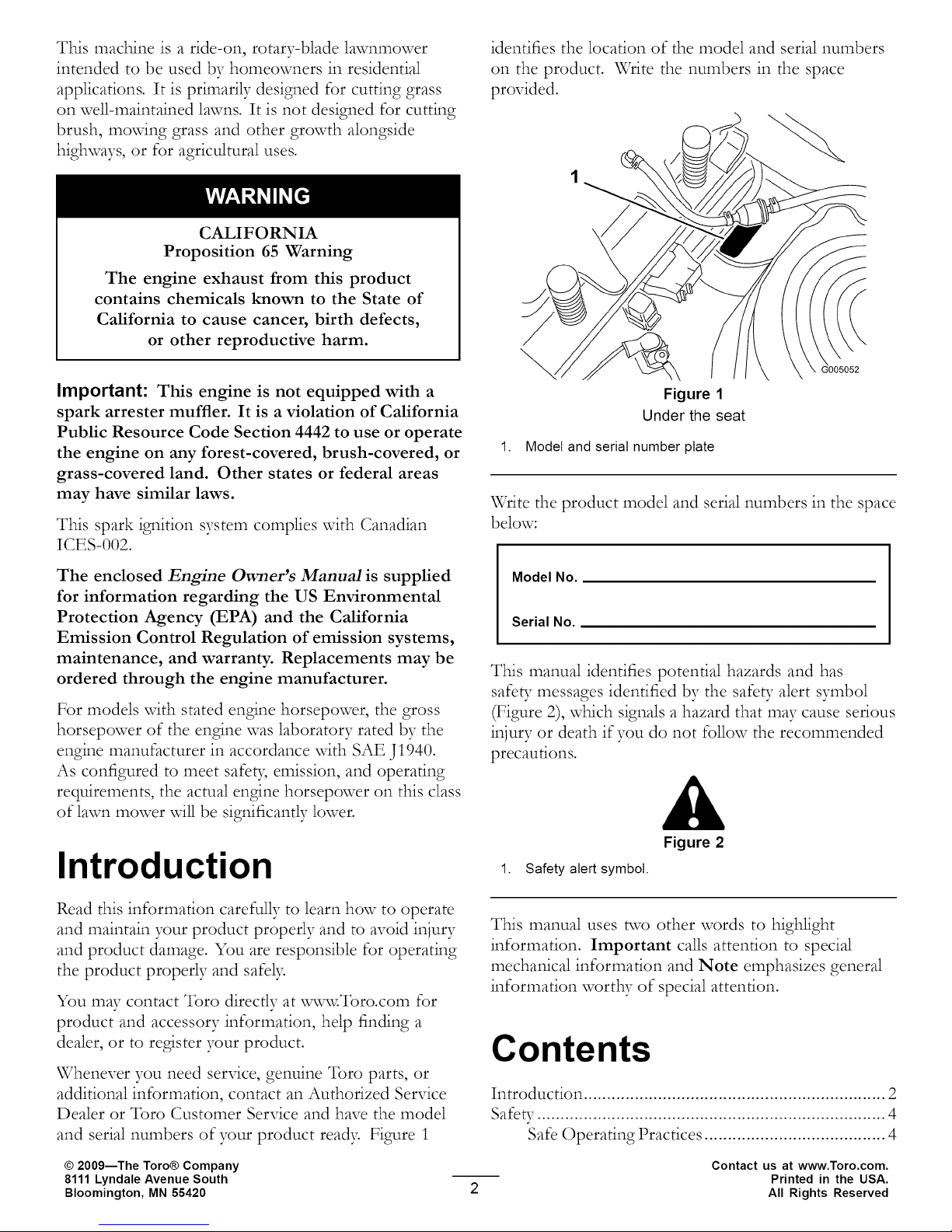
identifies the location of the model and serial numbers
on the product. Write the numbers in the space
provided.
G005052
Figure 1
Under the seat
1. Model and serial number plate
Write the product model and serial numbers in the space
below:
The enclosed Engine Owner's ManuM is supplied
for information regarding the US Environmental
Protection Agency (EPA) and the California
Emission Control Regulation of emission systems,
maintenance, and warranty. Replacements may be
ordered through the engine manufacturer.
For models vdth stated engine horsepower, the gross
horsepower of the engine was laboratory rated by the
engine manufacturer in accordance with SAE J1940.
As configured to meet safeb; emission, and operating
requirements, the actual engine horsepower on this class
of lawn mower will be significantly lower.
Introduction
Read this information carefully to learn how to operate
and maintain your product properly and to avoid injury
and product damage. You are responsible for operating
the product properly and safely.
You may contact Toro directly at xw,w,¥:Toro.com for
product and accessory information, help finding a
dealer, or to register your product.
Whenever you need service, genuine Toro parts, or
additional information, contact an Authorized Service
Dealer or Toro Customer Service and have the model
and serial numbers of your product read> Figure 1
Model No.
Serial No.
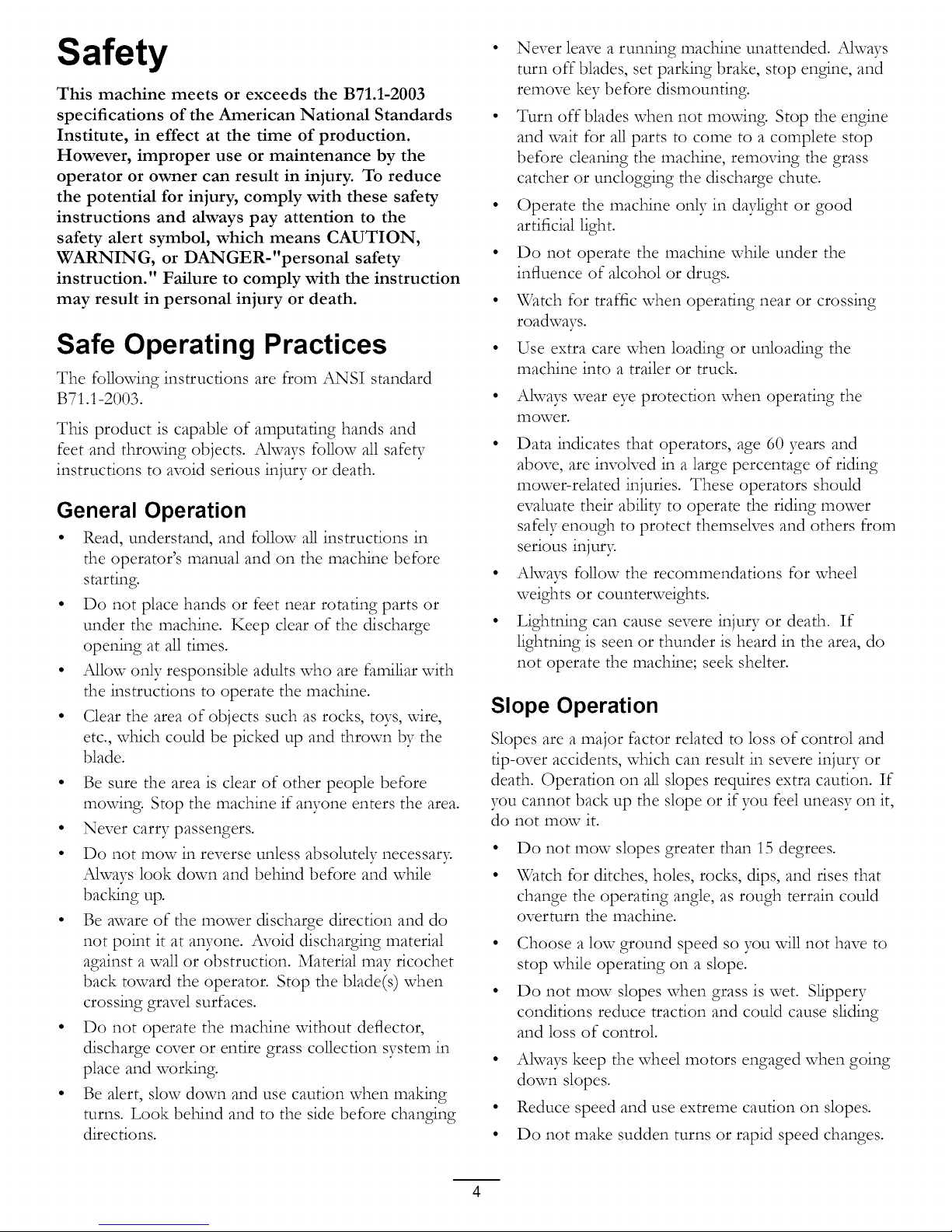
This manual identifies potential hazards and has
safeff messages identified by the safe_ Talert symbol
(Figure 2), which signals a hazard that may cause serious
injury or death if you do not follow the recommended
precautions.
Figure 2
1. Safety alert symbol.
This manual uses two other words to highlight
information. Important calls attention to special
mechanical information and Note emphasizes general
information worthy of special attention.
Contents
Introduction ................................................................. 2
Safeff ........................................................................... 4
Safe Operating Practices ....................................... 4
© 2009--The Toro® Company
8111 Lyndale Avenue South
Bloomington, MN 55420
Contact us at www.Toro.com.
Printed in the USA.
All Rights Reserved
Page 3

Toro Riding Mower Safety .................................... 6
Slope Indicator ..................................................... 7
Safety and Instructional Decals ............................. 8
Product Overview. ..................................................... 12
Controls ............................................................. 13
Operation ................................................................... 14
Think Safety First ............................................... 14
Recommended Gasoline ..................................... 14
ChecMng the Engine Oil Level ............................ 16
Starting the Engine ............................................. 16
Operating the Blades .......................................... 17
Stopping the Engine ........................................... 18
The Safety Interlock System ................................ 18
Driving Forward or Backward ............................. 19
Stopping the Machine ......................................... 20
Adjusting the Height of Cut ................................ 20
Positioning the Seat ............................................ 20
Adjusting the Motion Control Levers .................. 20
Pushing the Machine by Hand ............................. 21
Grass Deflector .................................................. 22
Operating Tips ................................................... 22
Maintenance ............................................................... 24
Recommended Maintenance Schedule(s) ................ 24
Premaintenance Procedures .................................... 25
Raising the Seat .................................................. 25
Accessing the Battery ......................................... 25
Lubrication ............................................................. 25
Greasing the Bearings ......................................... 25
Engine Maintenance ............................................... 26
Servicing the Air Cleaner .................................... 26
Servicing the Engine Oil ..................................... 27
Servicing the Spark Plug ..................................... 29
Cleaicing the Blower Housing .............................. 29
Fuel System Maintenance ....................................... 30
Replacing the Fuel Filter ..................................... 30
Electrical System Maintenance ................................ 31
Charging the Battery ........................................... 31
Servicing the Fuses ............................................. 32
Drive System Maintenance ..................................... 33
Chec_ng the Tire Pressure ................................. 33
Mower Maintenance ............................................... 34
Servicing the Cutting Blades ............................... 34
Leveling the Mower Deck ................................... 36
Removing the Mower ......................................... 38
Mower Belt Maintenance .................................... 39
Installing the Mower ........................................... 39
Replacing the Grass Deflector ............................. 39
CleaIcing ................................................................. 40
Washing the Underside of the Mower .................. 40
Storage ....................................................................... 41
Cleaicing and Storage .......................................... 41
Troubleshooting ......................................................... 42
Schematics ................................................................. 44
Conditions and Products Covered under The
Toro Total Coverage Guarantee ...................... 48
Limited Warranty for Commercial Use ................ 48
Owner Responsibilities ....................................... 48
Items and Conditions Not Covered ..................... 48
Instructions for Obtaining Warranty
Service ........................................................... 48
General Conditions ............................................ 48
Countries Other than the Uicited States or
Canada ........................................................... 48
Page 4
Safety
This machine meets or exceeds the B71.1-2003
specifications of the American National Standards
Institute, in effect at the time of production.
However, improper use or maintenance by the
operator or owner can result in injury. To reduce
the potential for injury, comply with these safety
instructions and always pay attention to the
safety alert symbol, which means CAUTION,
WARNING, or DANGER-"personal safety
instruction." Failure to comply with the instruction
may result in personal injury or death.
• Never leave a running machine unattended. Always
turn off blades, set paring brake, stop engine, and
remove key before dismounting.
• Turn off blades when not mowing. Stop the engine
and wait for all parts to come to a complete stop
before cleaning the machine, removing the grass
catcher or unclogging the discharge chute.
• Operate the machine only in daylight or good
artificial light.
• Do not operate the machine while under the
influence of alcohol or drugs.
• Watch for traffic when operating near or crossing
roadways.
Safe Operating Practices
The following instructions are from ANSI standard
B71.1-2003.
This product is capable of amputating hands and
feet and throwing objects. Always follow all safety
instructions to avoid serious injury or death.
General Operation
• Read, understand, and follow all instructions in
the operator's manual and on the machine before
starting.
• Do not place hands or feet near rotating parts or
under the machine. Keep dear of the discharge
opening at all times.
• Allow only responsible adults who are familiar with
the instructions to operate the machine.
• Clear the area of objects such as rocks, toys, wire,
etc., which could be picked up and thrown by the
blade.
• Be sure the area is clear of other people before
mowing. Stop the machine if awone enters the area.
• Never carry passengers.
• Do not mow in reverse unless absolutely necessar>
Always look down and behind before and while
bac_ng up.
• Be aware of the mower discharge direction and do
not point it at awone. Avoid discharging material
against a wall or obstruction. Material mW ricochet
back toward the operator. Stop the blade(s) when
crossing gravel surfaces.
• Do not operate the machine without deflector,
discharge cover or entire grass collection system in
place and wor_ng.
• Be alert, slow down and use caution when maMng
turns. Look behind and to the side before changing
directions.
• Use extra care when loading or unloading the
machine into a trailer or truck.
Always wear eye protection when operating the
mower.
• Data indicates that operators, age 60 years and
above, are involved in a large percentage of riding
mower-related injuries. These operators should
evaluate their ability to operate the riding mower
safely enough to protect themselves and others from
serious injur>
• Always follow the recommendations for wheel
weights or counterweights.
• Lightning can cause severe injury or death. If
lightning is seen or thunder is heard in the area, do
not operate the machine; seek shelter.
Slope Operation
Slopes are a major factor related to loss of control and
tip-over accidents, which can result in severe injury or
death. Operation on all slopes requires extra caution. If
you cannot back up the slope or if you feel uneasy on it,
do not mow it.
Do not mow slopes greater than 15 degrees.
Watch for ditches, holes, rocks, dips, and rises that
change the operating angle, as rough terrain could
overturn the machine.
• Choose a low ground speed so you will not have to
stop while operating on a slope.
• Do not mow slopes when grass is wet. Slippery
conditions reduce traction and could cause sliding
and loss of control.
• Always keep the wheel motors engaged when going
down slopes.
• Reduce speed and use extreme caution on slopes.
• Do not make sudden turns or rapid speed changes.
Page 5

Removeor markobstaclessuchasrocks,treelimbs,
etc. fromthemovdngarea.Tallgrasscanhide
obstacles.
Avoidsuddenstartswhenmovdnguphillbecause
themowermaytip backwards.
Be aware that loss of traction may occur going
downhill. Weight transfer to the front wheels may
cause drive wheels to slip and cause loss of brak:ing
and steering.
Ahvays avoid sudden starting or stopping on a
slope. If tires lose traction, disengage the blades and
proceed slovdy off the slope.
Use extreme care with grass catchers or other
attachments. These can change the stabiliD- of the
machine and cause loss of control.
Do not try to stabilize the machine by putting your
foot on the ground.
Towing
A hitch -kitis available for this machine and can be
obtained by contacting an Authorized Toro Dealer.
Do not tow without first installing this manufacturer
approved hitch. The follovdng guidelines apply when
towing with the approved hitch -kitinstalled.
• Tow only vdth a machine that has a hitch designed
for towing. Do not attach towed equipment except
at the hitch point.
• Follow the manufacturer's recommendation for
weight limits for towed equipment and towing on
slopes.
• Never allow children or others in or on towed
equipment.
• On slopes, the weight of the towed equipment may
cause loss of traction and loss of control.
• Travel slowly and allow extra distance to stop.
Do not mow near drop-offs, ditches, steep banks
or water. Wheels dropping over edges can cause
rollovers, which may result in serious injur B death
or drowning.
Use a walk behind mower and/or a hand trimmer
near drop-offs, ditches, steep banks or water.
Children
Tragic accidents can occur if the operator is not alert to
the presence of children. Children are often attracted to
the machine and the mowing activi_: Never assume that
children vdll remain where you last saw them.
Keep children out of the mowing area and under
the watchful care of another responsible adult, not
the operator.
Be alert and turn the machine off if children enter
the area.
Before and while bac "tdng or changing direction, look
behind, down, and side-to-side for small children.
Never carry children, even with the blades off. They
may fall off and be seriously injured or interfere vdth
safe machine operation.
Children who have been given rides in the past may
suddenly appear in the movdng area for another ride
and be run over or backed over by the mower.
Never allow children to operate the machine.
Use extra care when approaching blind corners,
shrubs, trees, the end of a fence or other objects that
may obscure vision.
Service
Safe Handling of Gasoline:
To avoid personal injury or property damage, use extra
care when handling gasoline and other fuels. They are
flammable and the vapors are explosive.
• Extinguish all cigarettes, cigars, pipes and other
sources of ignition.
• Use only an approved container.
• Never remove the gas cap or add fuel when the
engine is running. Allow the engine to cool before
refueling.
• Never refuel the machine indoors.
• Never store the machine or fuel container inside
where there is an open flame, such as near a water
heater or furnace.
Never fill containers inside a vehicle or on a truck or
trailer vdth a plastic liner. Ahvays place containers on
the ground away from your vehicle before filling.
Remove gas-powered equipment from the truck
or trailer and refuel it on the ground. If this is not
possible, then refuel such equipment vdth a portable
container, rather than from a gasoline dispenser
nozzle.
• Keep the nozzle in contact vdth the rim of the fuel
tank or container opening at all times until the fueling
is complete. Do not use a nozzle lock-open device.
• If fuel is spilled on clothing, change clothing
immediatel3:
• Never overfill the fuel tank. Replace gas cap and
tighten secure1>
Page 6
General Service:
• Never operate a machine inside a closed area. Engine
exhaust contains carbon monoxide, which is an
odorless, deadly poison that can _ll you.
• Keep nuts and bolts tight, especially the blade
attachment bolts. Keep equipment in good
condition.
• Never tamper with safeff devices. Check their
proper operation regularly.
• Keep the machine free of grass, leaves, or other
debris build-up. Clean up oil or fuel spillage fuel
soaked debris. Allow the machine to cool before
storing.
• Stop and inspect the equipment if you strike an
object. Repair, if necessar B before restarting.
• Never make aW adjustments or repairs with the
engine running.
• Grass catcher components are subject to wear,
damage and deterioration, which could expose
moving parts or allow objects to be thrown.
Frequently check components and replace vdth
manufacturers' recommended parts, when necessar>
Battery gases can explode. Keep cigarettes, sparks
and flames away from batter>
Use only Toro approved attachments. Warranty may
be voided if used vdth unapproved attachments.
If loading the machine onto a trailer or truck, use a
single, full-vddth ramp onl> The ramp angle should
not exceed 15 degrees.
Note: Determine the left and right sides of the
machine from the normal operating position.
• Mower blades are sharp and can cut. Wrap the
blade(s) or wear gloves, and use extra caution when
servicing them.
• Check for proper brake operation frequentl> Adjust
and service as required.
• Maintain or replace safety and instruction decals as
neces sary.
• Use only genuine Toro replacement parts to ensure
that original standards are maintained.
Toro Riding Mower Safety
The follovdng list contains safe_ _information specific to
Toro products or other safe_ Tinformation that you must
know that is not included in the ANSI standards.
• Stop the engine, disconnect spark plug wire(s) and
remove key before performing any service, repairs,
maintenance or adjustments.
• Keep hands, feet, hair, and loose clothing away from
attachment discharge area, underside of mower and
aW moving parts while engine is running.
• Do not touch equipment or attachment parts which
may be hot from operation. Allow to cool before
attempting to maintain, adjust or service.
• Battery acid is poisonous and can cause burns. Avoid
contact with s_n, eyes, and clothing. Protect your
face, eyes, and clothing when wor_ng with a batter>
Page 7
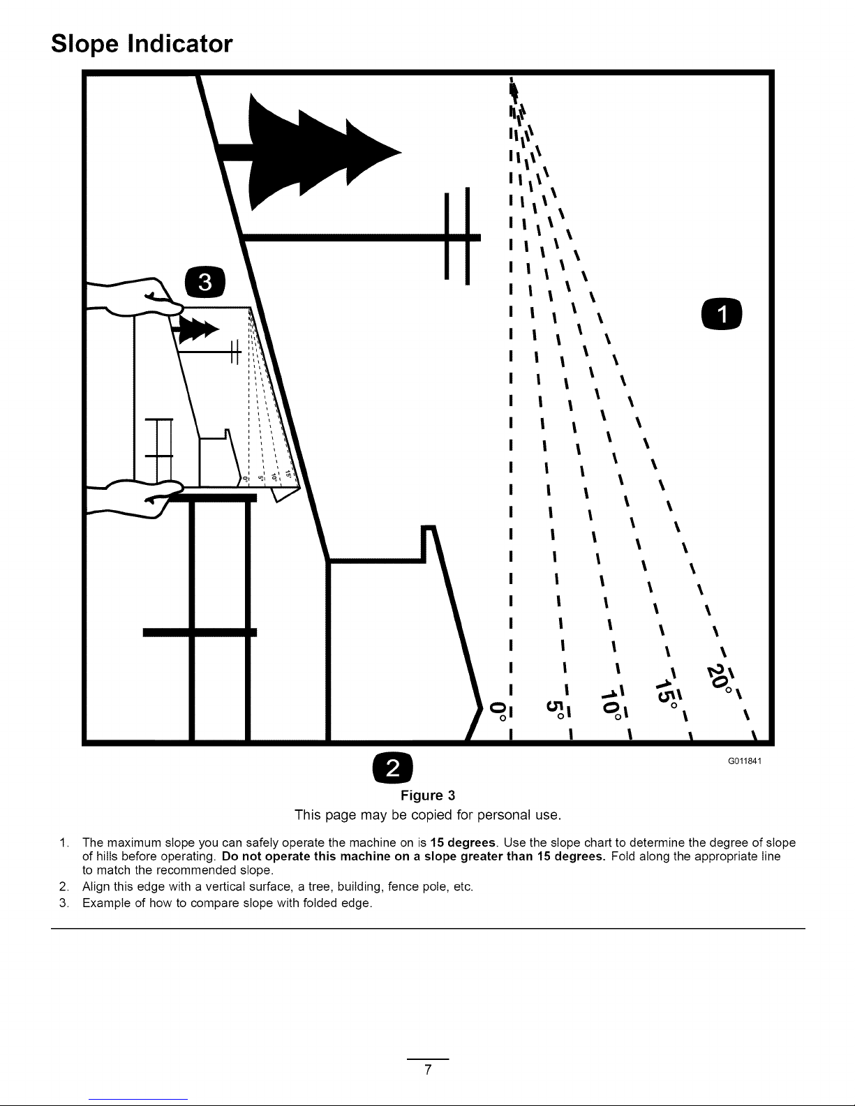
Slope Indicator
t
llll\
II i l\
I I if\\
llll \
llll \
I I II \
I I iI \
I I l I \
I I l I \
I I l l \
I I l l \
I I l l \
I I l l \
I I l l \
I I l
I I l
\ \
\
\
I | 1 l
I I l l
I I l l
I I l l
I I 1 l
I I 1
I I I
I I I
\
\
\
\
\
\
\
\ \
\ \
1. The maximum slope you can safely operate the machine on is 15 degrees. Use the slope chart to determine the degree of slope
of hills before operating. Do not operate this machine on a slope greater than 15 degrees. Fold along the appropriate line
to match the recommended slope.
2. Align this edge with a vertical surface, a tree, building, fence pole, etc.
3. Example of how to compare slope with folded edge.
0
\
G011841
Figure 3
This page may be copied for personal use.
Page 8
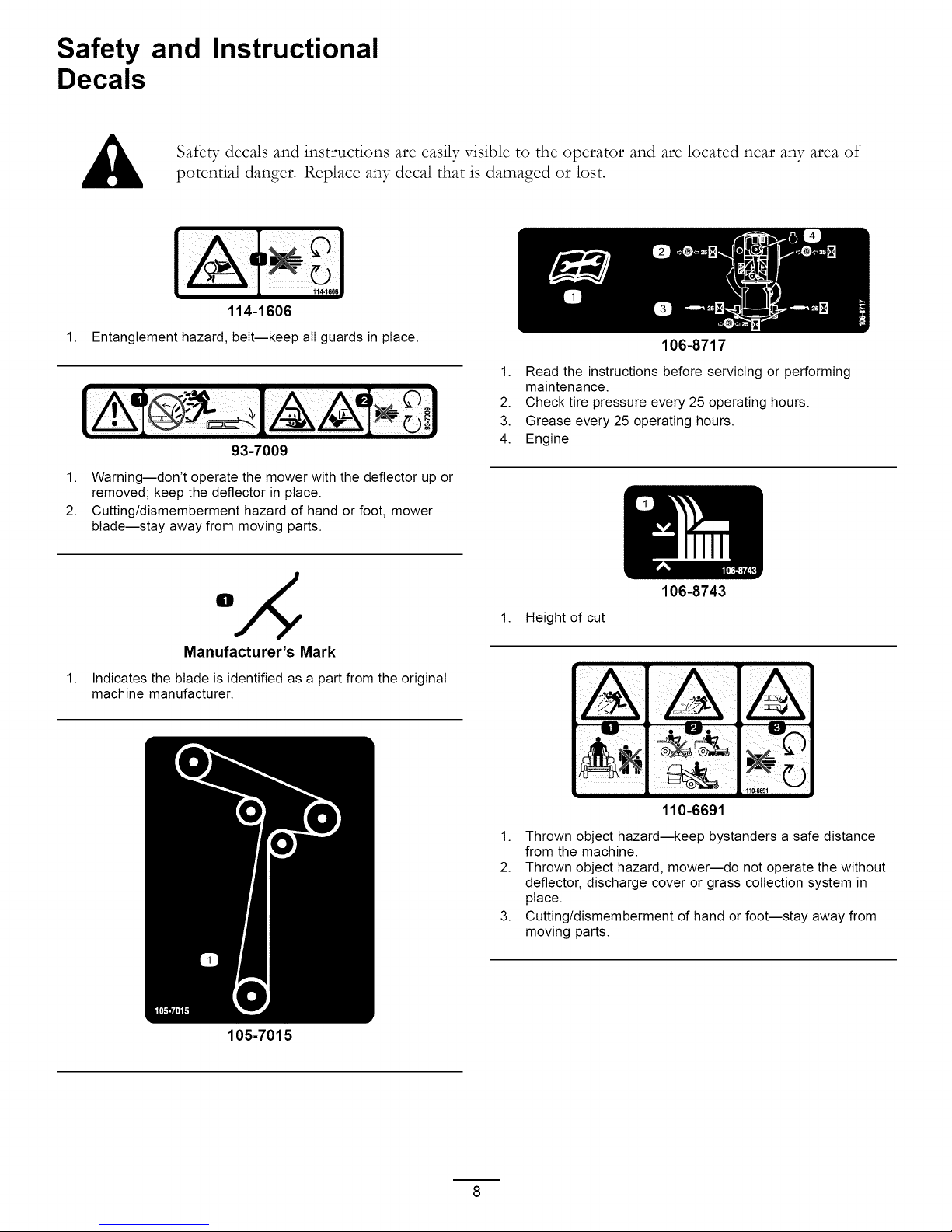
Safety and Instructional
Decals
Safety decals and instructions are easily visible to the operator and are located near any area of
potential danger. Replace any decal that is damaged or lost.
114-1606
1.
Entanglement hazard, belt--keep all guards in place.
93-7009
1. Warning--don't operate the mower with the deflector up or
removed; keep the deflector in place.
2. Cutting/dismemberment hazard of hand or foot, mower
blade--stay away from moving parts.
106-8717
1. Read the instructions before servicing or performing
maintenance.
2. Check tire pressure every 25 operating hours.
3. Grease every 25 operating hours.
4. Engine
Manufacturer's Mark
1.
Indicates the blade is identified as a part from the original
machine manufacturer.
105-7015
106-8743
1. Height of cut
110-6691
1. Thrown object hazard--keep bystanders a safe distance
from the machine.
2. Thrown object hazard, mower--do not operate the without
deflector, discharge cover or grass collection system in
place.
3. Cutting/dismemberment of hand or foot--stay away from
moving parts.
Page 9
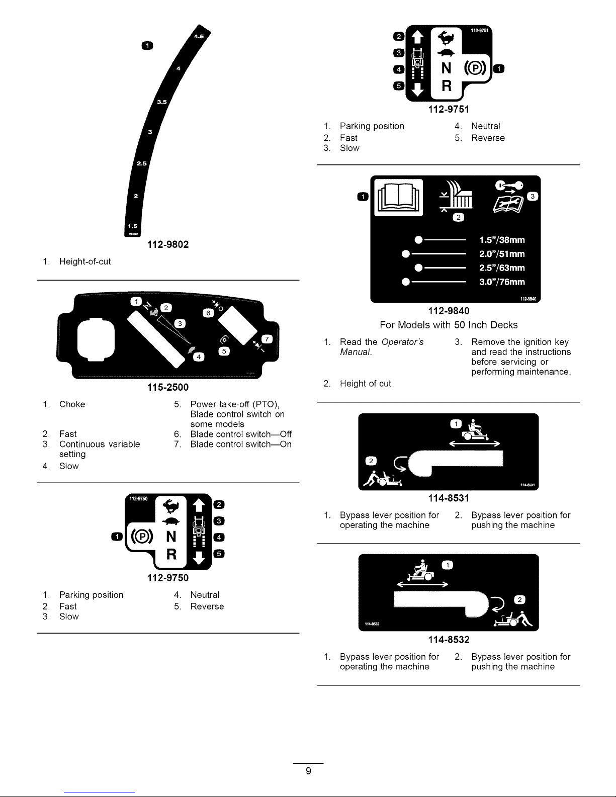
1. Height-of-cut
112-9802
1. Parking position
2. Fast
3. Stow
Ell
For Models with 50 Inch Decks
0
0
0
N(¢)
I!1
0
112-9751
4. Neutral
5. Reverse
112-9840
1. Choke
2. Fast
3. Continuous variable
setting
4. Stow
Ell
1. Parking position
2. Fast
3. Stow
115-2500
5. Power take-off (PTO),
Blade control switch on
some models
6. Blade control switch--Off
7. Blade control switch--On
0
0
N
0
0
112-9750
4. Neutral
5. Reverse
1. Read the Operator's 3.
Manual.
2. Height of cut
Remove the ignition key
and read the instructions
before servicing or
performing maintenance.
114-8531
1.
Bypass lever position for 2. Bypass lever position for
operating the machine pushing the machine
114-8532
1. Bypass lever position for 2. Bypass lever position for
operating the machine pushing the machine
Page 10

0 0 0 0 0
0 0
Some or all of these symbols
1. Explosion hazard
2. No fire, open flame, or
smoking.
3. Caustic liquid/chemical
burn hazard
4. Wear eye protection
5. Read the Operator's
Manual
0 0 0 0
Battery Symbols
are on your battery
6. Keep bystanders a safe
distance from the battery.
7. Wear eye protection;
explosive gases can
cause blindness and other
injuries
8. Battery acid can cause
blindness or severe burns.
9. Flush eyes immediately
with water and get medical
help fast.
10. Contains lead; do not
discard.
115-2469
1. Warning--read the Operator's Manual
2. Warning--read the instructions before servicing or performing maintenance; move the motion control levers to the park (brake)
position, remove the ignition key and disconnect the spark plug wire.
3. Cutting/dismemberment hazard, mower blade; entanglement hazard, belt--do not open or remove safety shields while engine is
running.
4. Tipping hazard--do not mow slopes greater than 15 degrees, avoid sudden and sharp turns while on slopes.
5. Loss of traction/controI hazard, slopes--loss of traction/controI on a slope, disengage the blade control switch (PTO), proceed
off the slope slowly.
6. Crushing/dismemberment hazard of bystanders, reversing; crushing/dismemberment hazard of bystanders--do not carry
passengers, look behind and down when reversing.
7. Thrown object hazard--keep bystanders a safe distance from the machine, pick up debris before operating, keep deflector in place.
10
Page 11

1. Fuelgauge
2. Full
115-2450
3. Half
4. Empty
11
Page 12
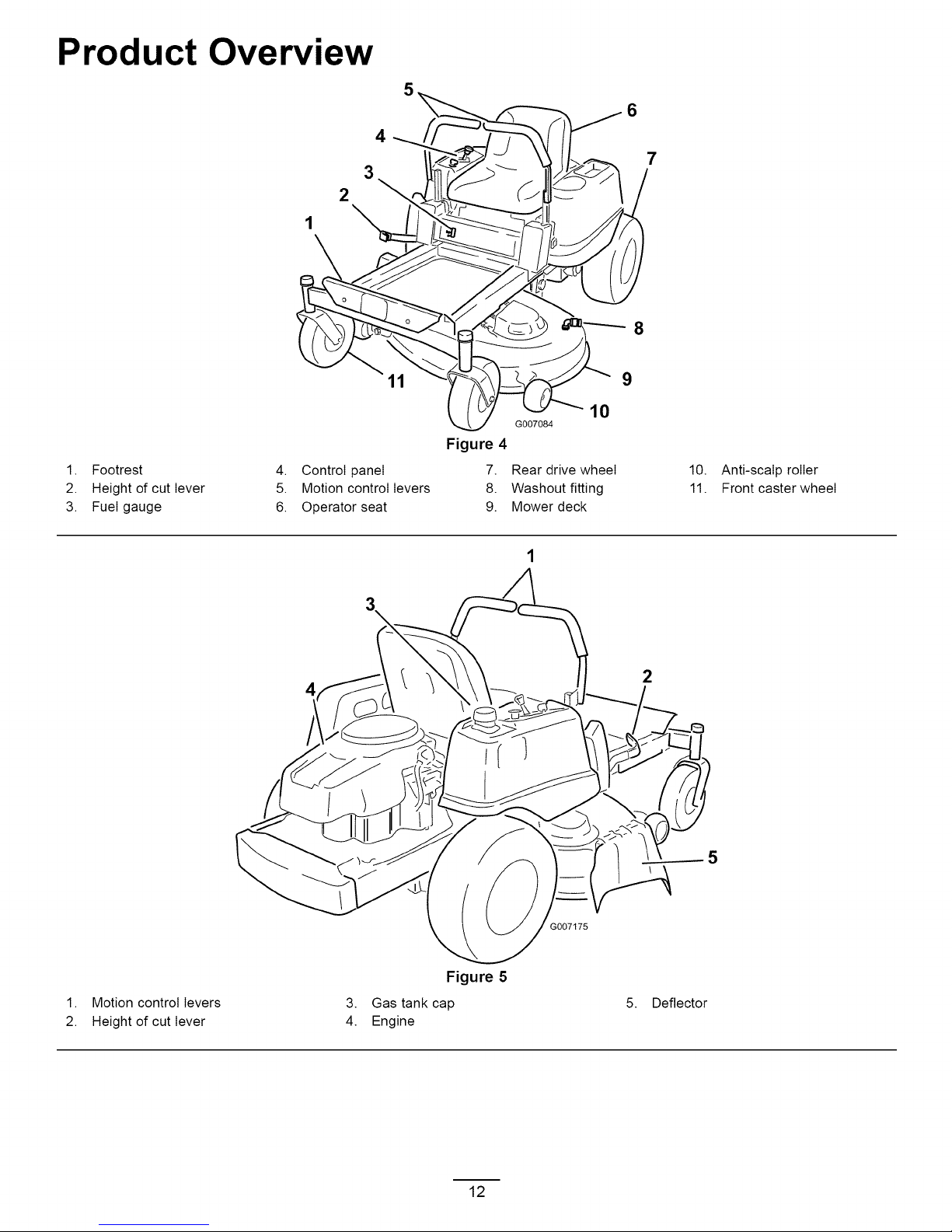
Product Overview
2
4
7
3
8
9
1. Footrest
2. Height of cut lever
3. Fuel gauge
Figure 4
4. Control panel 7.
5. Motion control levers 8.
6. Operator seat 9.
4
G007084
Rear drive wheel
Washout fitting
Mower deck
10
10. Anti-scalp roller
11. Front caster wheel
2
1. Motion control levers
2. Height of cut lever
3. Gas tank cap
4. Engine
7175
Figure 5
5. Deflector
12
Page 13
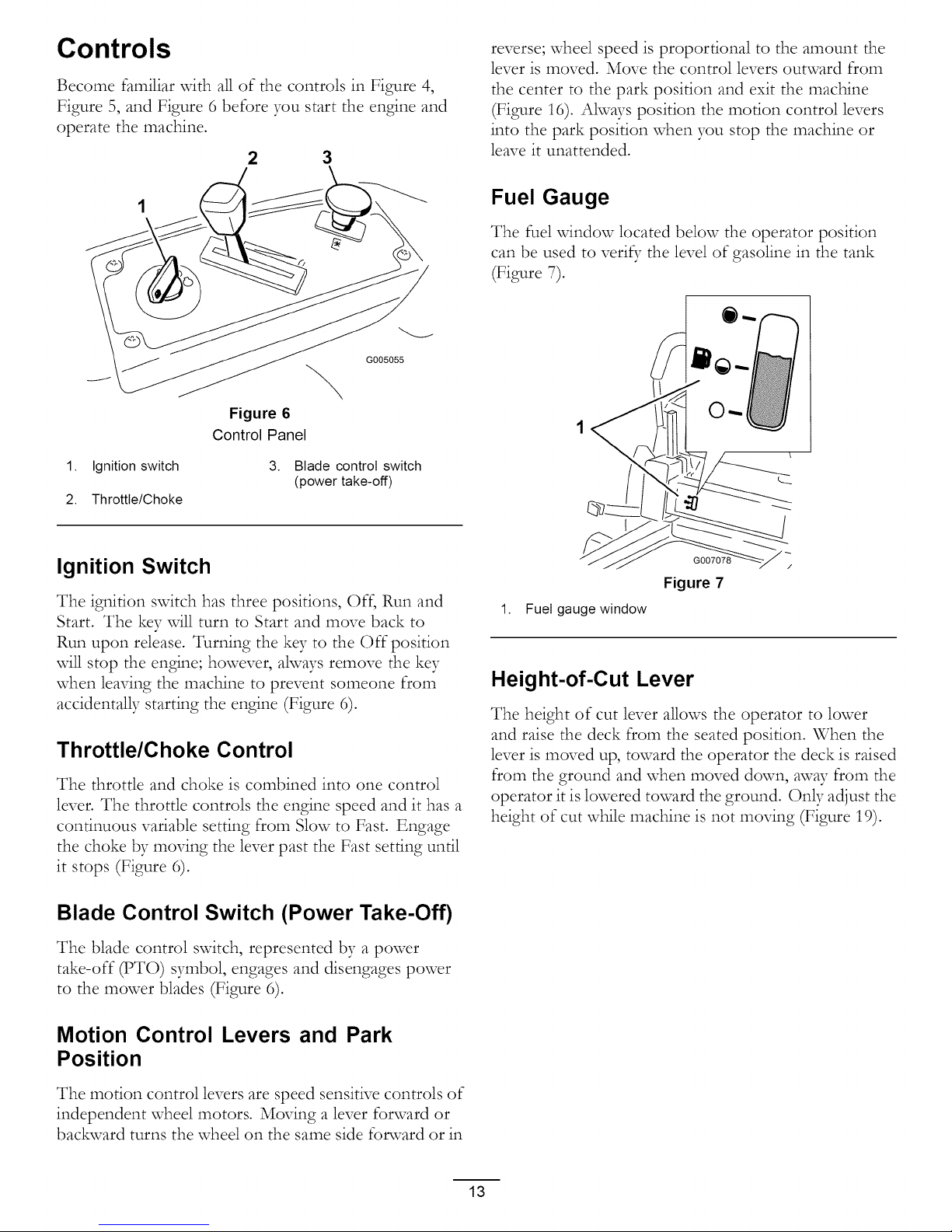
Controls
Become familiar vdth all of the controls in Figure 4,
Figure 5, and Figure 6 before you start the engine and
operate the machine.
2 3
G005055
Figure 6
Control Panel
reverse; wheel speed is proportional to the amount the
lever is moved. Move the control levers outward from
the center to the park position and exit the machine
(Figure 16). Always position the motion control levers
into the park position when you stop the machine or
leave it unattended.
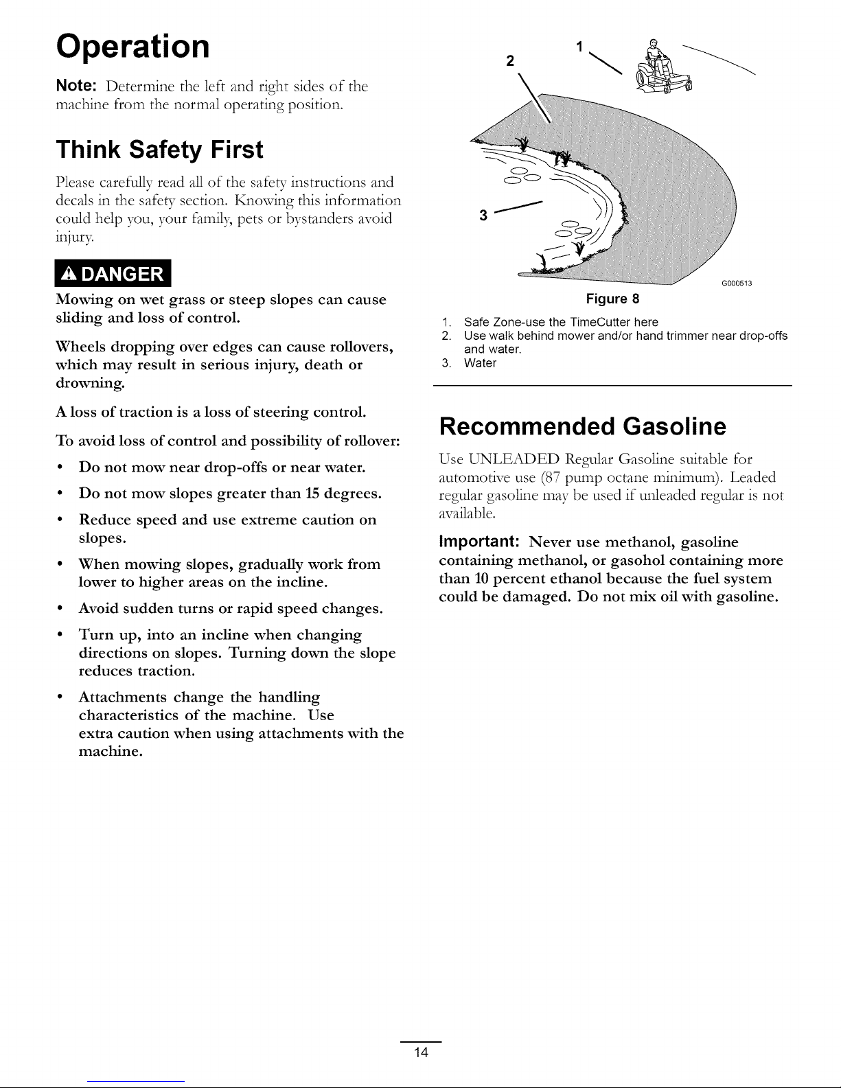
Fuel Gauge
The fuel vdndow located below the operator position
can be used to veri_; the level of gasoline in the tank
(Figure 7).
1. Ignition switch 3. Blade control switch
(power take-off)
2. Throttle/Choke
Ignition Switch
The ignition switch has three positions, Off, Run and
Start. The key will turn to Start and move back to
Run upon release. Turning the key to the Off position
will stop the engine; however, always remove the key
when leaving the machine to prevent someone from
accidentally starting the engine (Figure 6).
Throttle/Choke Control
The throttle and choke is combined into one control
lever. The throttle controls the engine speed and it has a
continuous variable setting from Slow to Fast. Engage
the choke by moving the lever past the Fast setting until
it stops (Figure 6).
Blade Control Switch (Power Take-Off)
G007078
Figure 7
1. Fuel gauge window
Height-of-Cut Lever
The height of cut lever allows the operator to lower
and raise the deck from the seated position. When the
lever is moved up, toward the operator the deck is raised
from the ground and when moved down, away from the
operator it is lowered toward the ground. Only adjust the
height of cut while machine is not moving (Figure 19).
The blade control switch, represented by a power
take-off (PTO) symbol, engages and disengages power
to the mower blades (Figure 6).
Motion Control Levers and Park
Position
The motion control levers are speed sensitive controls of
independent wheel motors. Moving a lever forward or
backward turns the wheel on the same side fonvard or in
13
Page 14
Operation
2
Note: Determine the left and right sides of the
machine from the normal operating position.
Think Safety First
Please carefully read all of the safe b- instructions and
decals in the safety section. Knowing this information
could help you, your famil3; pets or bystanders avoid
injur3=
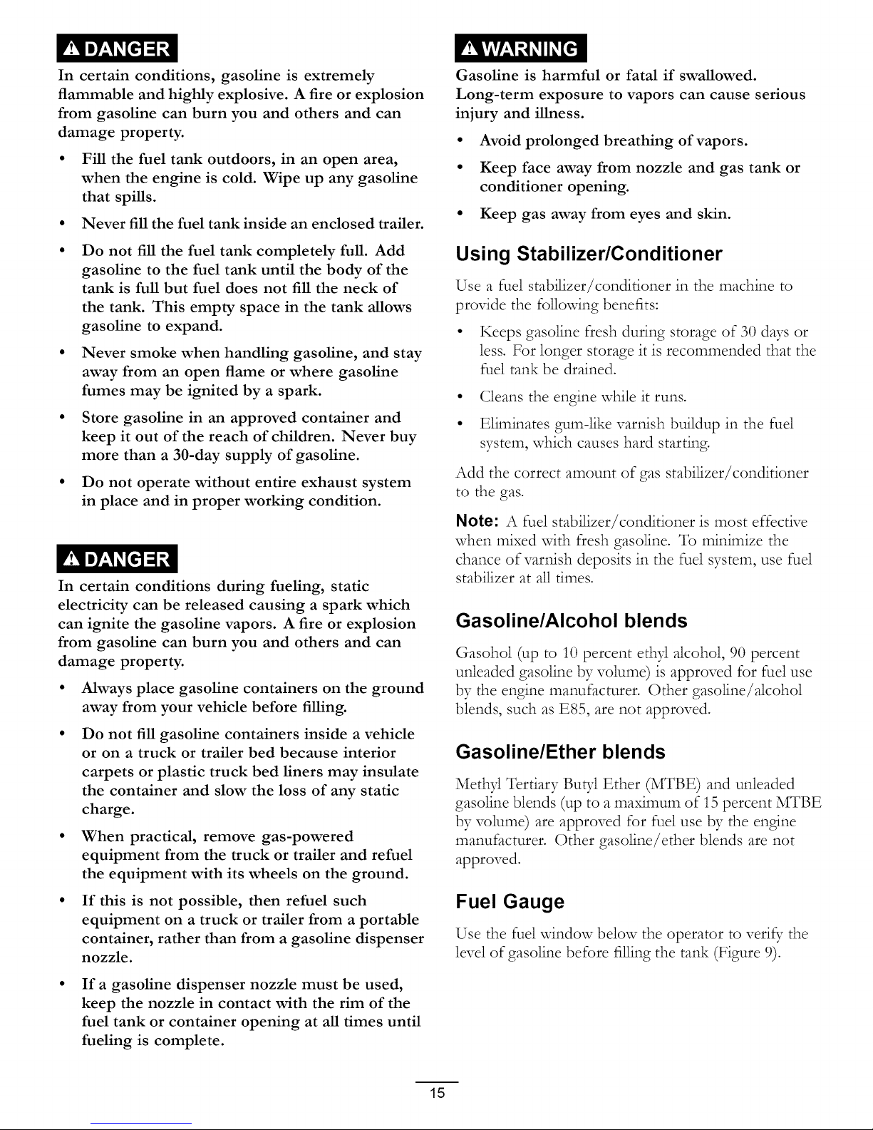
Mowing on wet grass or steep slopes can cause
sliding and loss of control.
Wheels dropping over edges can cause rollovers,
which may result in serious injury, death or
drowning.
A loss of traction is a loss of steering control.
To avoid loss of control and possibility of rollover:
• Do not mow near drop-offs or near water.
• Do not mow slopes greater than 15 degrees.
• Reduce speed and use extreme caution on
slopes.
• When mowing slopes, gradually work from
lower to higher areas on the incline.
• Avoid sudden turns or rapid speed changes.
\
G0005t3
Figure 8
1. Safe Zone-use the TimeCutter here
2. Use walk behind mower and/or hand trimmer near drop-offs
and water.
3. Water
Recommended Gasoline
Use UNLEADED Regular Gasoline suitable for
automotive use (87 pump octane minimum). Leaded
regular gasoline may be used if unleaded regular is not
available.
Important: Never use methanol, gasoline
containing methanol, or gasohol containing more
than 10 percent ethanol because the fuel system
could be damaged. Do not mix oil with gasoline.
• Turn up, into an incline when changing
directions on slopes. Turning down the slope
reduces traction.
Attachments change the handling
characteristics of the machine. Use
extra caution when using attachments with the
machine.
14
Page 15
In certain conditions, gasoline is extremely
flammable and highly explosive. A fire or explosion
from gasoline can burn you and others and can
damage property.
• Fill the fuel tank outdoors, in an open area,
when the engine is cold. Wipe up any gasoline
that spills.
• Never fill the fuel tank inside an enclosed trailer.
Gasoline is harmful or fatal if swallowed.
Long-term exposure to vapors can cause serious
injury and illness.
• Avoid prolonged breathing of vapors.
• Keep face away from nozzle and gas tank or
conditioner opening.
• Keep gas away from eyes and skin.
Do not fill the fuel tank completely full. Add
gasoline to the fuel tank until the body of the
tank is full but fuel does not fill the neck of
the tank. This empty space in the tank allows
gasoline to expand.
Never smoke when handling gasoline, and stay
away from an open flame or where gasoline
fumes may be ignited by a spark.
Store gasoline in an approved container and
keep it out of the reach of children. Never buy
more than a 30-day supply of gasoline.
Do not operate without entire exhaust system
in place and in proper working condition.
In certain conditions during fueling, static
electricity can be released causing a spark which
can ignite the gasoline vapors. A fire or explosion
from gasoline can burn you and others and can
damage property.
Always place gasoline containers on the ground
away from your vehicle before filling.
Do not fill gasoline containers inside a vehicle
or on a truck or trailer bed because interior
carpets or plastic truck bed liners may insulate
the container and slow the loss of any static
charge.
When practical, remove gas-powered
equipment from the truck or trailer and refuel
the equipment with its wheels on the ground.
Using Stabilizer/Conditioner
Use a fuel stabilizer/conditioner in the machine to
provide the following benefits:
• Keeps gasoline flesh during storage of 30 days or
less. For longer storage it is recommended that the
fuel tank be drained.
• Cleans the engine while it runs.
• Eliminates gum-like varnish buildup in the fuel
system, which causes hard starting.
Add the correct amount of gas stabilizer/conditioner
to the gas.
Note: A fuel stabilizer/conditioner is most effective
when mixed with fresh gasoline. To minimize the
chance of varnish deposits in the fuel system, use fuel
stabilizer at all times.
Gasoline/Alcohol blends
Gasohol (up to 10 percent ethJ alcohol, 90 percent
unleaded gasoline by volume) is approved for fuel use
by the engine manufacturer. Other gasoline/alcohol
blends, such as E85, are not approved.
Gasoline/Ether blends
Methyl Tertiary Bu@ Ether (MTBE) and unleaded
gasoline blends (up to a maximum of 15 percent MTBE
by volume) are approved for fuel use by the engine
manufacturer. Other gasoline/ether blends are not
approved.
If this is not possible, then refuel such
equipment on a truck or trailer from a portable
container, rather than from a gasoline dispenser
nozzle.
If a gasoline dispenser nozzle must be used,
keep the nozzle in contact with the rim of the
fuel tank or container opening at all times until
fueling is complete.
Fuel Gauge
Use the fuel window below the operator to veri_- the
level of gasoline before filling the tank (Figure 9).
15
Page 16

Figure 9
1. Fuel gauge window
Filling the Fuel Tank
,
Shut the engine off and set the motion controls to
the park position. Raise the seat so the gas tank is
visible while fueling.
,
Clean around the fuel tank cap and remove the cap.
3.
Add unleaded regular gasoline until the body of the
tank is full but fuel does not fill the neck of the
tank (Figure 10). This space in the neck of the tank
allows gasoline to expand. Do not fill the fuel tank
completely full.
,
Install the fuel tank cap securel> Wipe up any
gasoline that may have spilled.
\
Checking the Engine Oil Level
Before you start the engine and use the machine, check
the oil level in the engine crankcase; refer to Chec_ng
the Oil Level in the Engine Maintenance section.
Starting the Engine
1. Sit down on the seat and move the motion controls
outward to the park position.
2. Disengage the blades by moving the blade control
switch to Off (Figure 11).
G005056
Figure 11
1. Control panel 2.
,
Move the throttle lever to Choke before starting a
cold engine (Figure 12).
Note: A warm or hot engine may not require
cho_ng.
Blade control switch--Off
position
Figure 10
1. Gas tank body 3. Fill to here, approximately
2. Gas tank neck 4. Gas tank opening
G005302
16
Page 17

G005057
2 /
.2
Figure 12
1. Control panel 4. Fast
2. Throttle/choke 5. Continuous variable
lever--choke position setting
3. Choke 6. Stow
2
G005058
Figure 13
1. Control panel 4. Off
2. Ignition key--run position 5. Run
3. Ignition key--start position 6. Start
After the engine starts, move the throttle lever to
Fast (Figure 12)• If the engine stalls or hesitates,
move the throttle lever back to Choke for a few
seconds. Repeat this as required.
,
Turn the ignition key to Start to energize the starter.
When the engine starts, release the key (Figure 13).
Important: Do not engage the starter for more
than 10 seconds at a time. If the engine fails
to start, allow a 60 second cool-down period
between attempts. Failure to follow these
instructions can damage the starter motor.
Operating the Blades
The blade control switch, represented by a power
take-off (PTO) symbol, engages and disengages power
to the mower blades. This switch controls power to aW
attachments that draw power from the engine, including
the mower deck and cutting blades.
Engaging the Blades
Important: Do not engage the blades when
parked in tall grass. Belt or clutch damage can
occur.
,
Release pressure on the motion control levers and
place the machine in neutral.
2. Move the throttle to the Fast position.
Note: Always engage the blades with the throttle
in the Fast position.
,
Pull up on the blade control switch to move it to
the On position and engage the blades (Figure 14).
17
Page 18

The Safety Interlock System
G005059
Figure 14
1. Control panel 2.
Blade control switch--On
position
Disengaging the Blades
Push down on the blade control switch to move it to
the Off position and disengage the blades (Figure 15).
If safety
damaged the machine could operate unexpectedly
causing personal injury.
• Do not tamper with the interlock switches.
• Check the operation of the interlock switches
interlock switches are disconnected or
daily and replace any damaged switches before
operating the machine.
Understanding the Safety Interlock
System
The safety interlock system is designed to prevent the
engine from starting unless:
• The blades are disengaged.
• The motion control levers are in the park position.
The safety interlock system also is designed to stop
the engine when the control levers are out of the park
position and you rise from the seat when the blades
are engaged.
G005056
>,
Figure 15
1. Control panel
Stopping the Engine
1. Disengage the blades by moving the blade control
svdtch to Off (Figure 15).
2. Move the throttle lever to between Fast and half
throttle (Figure 13).
3. Turn the igaition key to Off (Figure 12) and remove
the ke3=
2. Blade control switch--Off
Testing the Safety Interlock System
Test the safety interlock system before you use the
machine each time. If the safety system does not
operate as described belov_, have an Authorized Service
Dealer repair the safety system immediatel3=
,
While sitting on the seat, with the control levers in
park position, and move the blade control switch
to On. Try starting the engine; the engine should
not crank.
,
While sitting on the seat, move the blade control
svdtch to Off. Move either motion control lever
to the center, unlocked position. Try starting the
engine; the engine should not crank. Repeat vdth
the other motion control lever.
,
While sitting on the seat, move the blade control
switch to Off, and lock the motion control levers in
the park position. Start the engine. While the engine
is running, engage the blade control svdtch, and rise
slightly from the seat; the engine should stop.
,
While sitting on the seat, move the blade control
switch to Off, and lock the motion control levers
in the park position. Start the engine. While the
engine is running, move the motion control levers
to the center, unlocked position, engage the blade
control switch, and rise slightly from the seat; the
engine should stop.
18
Page 19

Driving Forward or Backward
The throttle control regulates the engine speed as
measured in rpm (revolutions per minute). Place
the throttle control in the Fast position for best
performance. Always operate in the fu_ throttle
position.
The machine can spin very rapidly. The operator
may lose control of the machine and cause personal
injury or damage to the machine.
• Use caution when making turns.
• Slow the machine down before making sharp
turns.
Figure 17
To go straight, apply equal pressure to both motion
control levers (Figure 16).
To turn, release pressure on the motion control lever
toward the direction you want to turn (Figure 16).
1 2
Figure 16
1. Park (brake) position 3. Forward
2. Center unlock position 4. Backward
Forward
2 1
4
G004532
The farther you move the motion control levers in
either direction, the faster the machine vdll move in
that direction.
To stop, pull the motion control levers to neutral.
Backward
,
Move the levers to the center, unlocked position.
2.
To go backward, slowly pull the motion control
levers rearward (Figure 18).
II, I
1. Move the levers to the center, unlocked position.
2. To go forward, slowly push the motion control
levers forward (Figure 16).
G008953
Figure 18
To go straight, apply equal pressure to both motion
control levers (Figure 18).
19
Page 20

Toturn, release the pressure on the motion control
lever toward the direction you want to turn.
To stop, push the motion control levers to neutral.
,
Raise the seat and loosen the adjustment knob just
enough that seat can move (Figure 20).
Stopping the Machine
To stop the machine, move the motion control levers to
neutral and outward to the park position, disengage the
blade control switch, ensure the throttle is in the fast
position, and turn the ignition key to off. Remember to
remove the key from the ignition switch.
Children or bystanders may be injured if they
move or attempt to operate the mower while it is
unattended.
Always remove the ignition key and move the
motion control levers outward to the park position
when leaving the machine unattended, even if just
for a few minutes.
Adjusting the Height of Cut
1. Raise the height-of-cut lever to the transport
position, cutting height position 4.5 (also the
4-1/2 inch [115 mm]) (Figure 19).
1
\
G005061
Figure 20
1. Adjustment knob
2. Move the seat to the desired position and tighten
the knob.
Adjusting the Motion Control
Levers
7
8
1. Height-of-cut lever 5. 3 inch (76 mm)
2. 4.5 inch (115 mm), 6. 2.5 inch (64 mm)
Transport position
3. 4 inch (102 mm) 7. 2 inch (51 mm)
4. 3.5 inch (89 mm) 8. 1.5 inch (38 mm)
2. To adjust the height of cut, pull inward and up on
the lever and move it to the desired position.
Positioning the Seat
Adjusting the Height
The motion control levers can be adjusted higher or
lower for maximum operator comfort.
1. Remove the 2 bolts holding the control lever to the
control arm shaft (Figure 21).
2. Move the control lever to the next set of holes.
Secure the lever with the 2 bolts (Figure 21).
The seat can move forward and backward. Position the
seat where you have the best control of the machine
and are most comfortable.
20
Page 21

,
2
Move the bypass levers rearward and then down
to lock them in place as shown in Figure 22 to
disengage the wheel motors. Repeat this on each
side of the machine.
5. Move the motion control levers inward to the
neutral position.
The machine is now able to be pushed t)37hand.
\
G005062
Figure 21
1. Control arm shaft 3. Slotted, upper hole
2. Control lever 4. Bolt
3. Repeat the adjustment for the opposite control
lever.
Adjusting the Tilt
The motion control levers can be tilted fore or aft for
maximum operator comfort.
1. Loosen the upper bolt holding the control lever to
the control arm shaft.
,
Loosen the lower bolt just enough to pivot the
control lever fore or aft (Figure 21). Tighten both
bolts to secure the control in the new position.
,
Repeat the adjustment for the opposite control
lever.
2
G007086
Figure 22
Right side shown
1. Bypass lever location
2. Lever position for pushing
the machine
3. Lever position for
operating the machine
To Operate the Machine
Move the bypass levers upward and push them forward,
to the middle of the horizontal slot (Figure 22) to
engage the wheel motors.
Pushing the Machine by Hand
Important: Always push the machine by hand.
Never tow the machine because damage may
Occur.
To Push the Machine
1. Park the machine on a level surface and disengage
the blade control switch.
,
Move the motion control levers outward to park
position, stop the engine, remove the ke5 and wait
for all moving parts to stop before leaving the
operating position.
,
Locate the bypass levers at the rear of the machine,
on the left and right side of the frame.
21
Page 22

Grass Deflector
Mowing Direction
The mower has a hinged grass deflector that disperses
clippings to the side and down toward the turf.
Without the grass deflector, discharge cover, or
complete grass catcher assembly mounted in
place, you and others are exposed to blade contact
and thrown debris. Contact with rotating mower
blade(s) and thrown debris will cause injury or
death.
Never remove the grass deflector from the
mower because the grass deflector routes
material down toward the turf. If the
grass deflector is ever damaged, replace it
immediately.
Never put your hands or feet under the mower.
Never try to clear discharge area or mower
blades unless you move the blade control switch
to Off and rotate the ignition key to Off. Also
remove the key and pull the wire off the spark
plug(s).
Alternate mowing direction to keep the grass standing
straight. This also helps disperse clippings which
enhances decomposition and fertilization.
Mow at Correct Intervals
Normally, mow every four days. But remember,
grass grows at different rates at different times. So
to maintain the same cutting height, which is a good
practice, mow more often in early spring. As the grass
growth rate slows in mid summer, mow less frequently.
If you cannot mow for an extended period, first mow
at a high cutting height; then mow again two days later
at a lower height setting.
Cutting Speed
To improve cut qualit3; use a slower ground speed.
Avoid Cutting Too Low
If the cutting width of the mower is wider than the
mower you previously used, raise the cutting height to
ensure that uneven turf is not cut too short.
Operating Tips
Fast Throttle Setting
For best mowing and maximum air circulation, operate
the engine at the Fast position. Air is required to
thoroughly cut grass clippings, so do not set the
height-of-cut so low as to totally surround the mower
t)37uncut grass. Akvays try to have one side of the
mower free from uncut grass, which allows air to be
drawn into the mower.
Cutting a Lawn for the First Time
Cut grass slightly longer than normal to ensure that the
cutting height of the mower does not scalp aW uneven
ground. However, the cutting height used in the past is
generally the best one to use. When cutting grass longer
than six inches tall, you may want to cut the lawn twice
to ensure an acceptable quali_ _of cut.
Cut 1/3 of the Grass Blade
Long Grass
If the grass is ever allowed to grow slightly longer than
normal, or if it contains a high degree of moisture, raise
the cutting height higher than usual and cut the grass at
this setting. Then cut the grass again using the lower,
normal setting.
When Stopping
If the machine's forward motion must be stopped while
mowing, a clump of grass clippings may drop onto your
lawn. To avoid this, move onto a previously cut area
with the blades engaged.
Keep the Underside of the Mower
Clean
Clean clippings and dirt from the underside of the
mower after each use. If grass and dirt build up inside
the mower, cutting quality will eventually become
unsatisfactor 7
Blade Maintenance
It is best to cut only about 1/3 of the grass blade.
Cutting more than that is not recommended unless
grass is sparse, or it is late fall when grass grows more
slowl>
Maintain a sharp blade throughout the cutting season
because a sharp blade cuts cleanly without tearing or
shredding the grass blades. Tearing and shredding turns
grass brown at the edges, which slows growth and
increases the chance of disease. Check the cutter blades
22
Page 23

daily for sharpness, and for any wear or damage. File
down aW nicks and sharpen the blades as necessar> If
a blade is damaged or worn, replace it immediately with
a genuine Toro replacement blade.
23
Page 24

Maintenance
Note: Determine the left and right sides of the machine from the normal operating position.
Recommended Maintenance Schedule(s)
Maintenance Service
Interval
Before each use or daily
Every 25 hours
Every 100 hours
Every 200 hours • Check spark plug condition and gap.
Every 500 hours • Replace the spark plug.
Before storage • Perform all maintenance procedures listed above before storage.
Maintenance Procedure
• Check the safety interlock system.
• Check the air cleaner for dirty, loose or damaged parts.
• Check the engine oil level.
• Check air intake and cooling areas, clean as necessary.
• Check the cutting blades.
• Inspect the grass deflector for damage
• Clean the mower housing.
• Grease all lubrication points.
• Service the paper element. (more often under extremely dusty, dirty conditions)
• Check tire pressure.
• Check the belts for wear/cracks.
• Replace the paper element. (more often under extremely dusty, dirty conditions)
• Change the engine oil and filter.
• Clean the blower housing (more often under extremely dusty, dirty conditions).
• Replace the fuel filter.
• Charge the battery and disconnect battery cables.
• Paint any chipped surfaces.
Important: Refer to your engine operator's manual for additional maintenance procedures.
If you leave the key in the ignition switch, someone could accidently start the engine and seriously injure
you or other bystanders.
Remove the key from the ignition and disconnect the wire from the spark plug before you do any
maintenance. Set the wire aside so that it does not accidentally contact the spark plug.
24
Page 25

Premaintenance
Procedures
Lubrication
Greasing the Bearings
Raising the Seat
Make sure the motion control levers are locked in the
park position Lift the seat forward
The following components can be accessed by raising
the seat:
• Serial plate
• Service decal
• Seat adjustment _ob
• Fuel filter
• Battery cables
Accessing the Battery
1 Raise the seat.
2. Remove the TORX :R:'head fasteners (T25) securing
the left cover to the frame as shown in Figure 23.
2
I
Service Interval: Every 25 hours--Grease all
lubrication points.
Grease Type: No. 2 General Purpose Lithium Base
Grease
1. Park the machine on a level surface and disengage
the blade control switch.
,
Move the motion control levers outward to the
park position, stop the engine, remove the key and
wait for all moving parts to stop before leaving the
operating position.
,
Clean the grease fittings (Figure 24 and Figure 25)
with a rag. Make sure to scrape any paint off of the
front of the fitting(s).
J 1
\
\
2
,,//_ G00506!
Figure 23
1.
Left cover 3. Battery
2.
Torx head fasteners (T25)
3. Lift the plastic cover away from the machine. Retain
all fasteners.
Replace the cover and secure it to the frame using the
fasteners removed previousl):
G005066
Figure 24
1. Front caster tire
Figure 25
Located on the seat pan underside
1. Read the instructions
before servicing or
performing maintenance.
2. Check tire pressure every
25 operating hours.
3. Grease every 25 operating
hours.
4. Engine
25
Page 26

,
Connect a grease gun to each fitting (Figure 24 and
Figure 25). Pump grease into the fittings until grease
begins to ooze out of the bearings.
5. Wipe up any excess grease.
Engine Maintenance
Servicing the Air Cleaner
Service Interval: Before each use or dail3_Check the
air cleaner for dirb, loose or damaged
parts.
This engine is equipped with a replaceable, high density
paper air cleaner element. Check the air cleaner daily or
before starting the engine. Check for a buildup of dirt
and debris around the air cleaner system. Keep this area
dean. Also check for loose or damaged components.
Replace all bent or damaged air cleaner components.
Note: Operating the engine with loose or damaged air
cleaner components could allow unfiltered air into the
engine causing premature wear and failure.
Note: Service the air cleaner more often under
extremely dusb. dirty conditions.
o
G005300 J
Figure 26
1. Knobs, air cleaner cover 3. Paper element
2. Air cleaner cover 4. Air cleaner base
Servicing Paper Element
Service Interval: Every 25 hours--Service the paper
dement. (more often under extremely
dust B dirty conditions)
Every 100 hours--Replace the paper
dement. (more often under extremely
dust B dirty conditions)
1. Remove the air cleaner cover (Figure 26).
2. Remove the air cleaner element with the integral
rubber seal (Figure 26).
3. Gently tap the pleated side of the paper element to
dislodge dirt. Do not wash the paper dement or
use pressurized air, as this will damage the element.
26
Page 27

Replace a dirt), bent, or damaged element. Handle
new elements carefully; do not use if the rubber seal
is damaged.
,
Clean all air cleaner components of any accumulated
dirt or foreign material. Prevent any dirt from
entering the carburetor.
Install the air cleaner element with the pleated side
"out" and seat the rubber seal onto the edges of the
air cleaner base (Figure 26).
,
Reinstall the air cleaner cover and secure with the
two M_obs (Figure 26)•
Servicing the Engine Oil
Oil Type: Detergent oil (API service SG, SH, SJ,or
higher)
Crankcase Capacity: 1.6 qt (1.5 1)when the filter is
changed
Viscosity: See the table below
USE THESE SAE VISCOSITY OILS
-20 0 20 3240 60 80 100
oF
40 -20 -40 6 10 20 30 40
°C
G005176
Figure 27
Checking the Oil Level
Service Interval: Before each use or daily--Check the
engine oil level.
,
Park the machine on a level surface, disengage the
blade control switch, stop the engine, and remove
the ke)_
,
Make sure the engine is stopped, level, and is cool so
the oil has had time to drain into the sump.
,
To keep dirt, grass clippings, etc., out of the engine,
clean the area around the oil fill cap/dipstick before
removing it.
,
Pull and remove the oil fill cap/dipstick; wipe oil
off. Reinsert the dipstick and push firmly into place
(Figure 28)•
L
Figure 28
1. Oil dipstick
2. Filler tube
Remove the dipstick and check the oil level.
(Figure 28).
The oil level should be up to, but not over, the F
mark on the dipstick.
,
If the level is lo\_ add oil of the proper type, up to
the F mark on the dipstick• Ahvays check the level
with the dipstick before adding more oil.
Note: To prevent extensive engine wear or damage,
ahvays maintain the proper oil level in the crankcase.
Never operate the engine with the oil level below the
"L" mark or over the "F" mark on the dipstick•
Changing the Oil and the Filter
Service Interval: Every 100 hours--Change the engine
oil and filter•
Refill with service class SG, SH, SJ or higher oil as
\ lscoslty Grades" table.specified in the " T" "
Change the oil and filter while the engine is still warm.
The oil will flow more freely and carry away more
impurities• Make sure the engine is level when filling,
chec_ng, or changing the oil.
Change the oil and oil filter as follows:
1. Start the engine and let it run until warm. This
warms the oil so it drains better.
3. Oil level
27
Page 28

,
Park the machine so that the drain side is slightly
lower than the opposite side to assure the oil drains
completel>
,
Disengage the blade control switch and move the
motion controls outward to the park position.
,
Stop the engine, remove the ke), and wait for all
moving parts to stop before leaving the operating
position.
Clean the area around the drain vak_e and on the
machine frame. Locate the oil drain hose and slide
it over the drain vakTe (Figure 29).
4
2
1. Oil drain valve
2. Machine frame
3. Oil drain hose
G007087
Figure 30
4. Pan
5. Oil filter
3
G007093
Figure 29
1. Oil drain hose Hole in frame
2. Drain valve Oil filter
,
Place the opposite end of the oil drain hose through
3.
4.
the drain hole in the frame (Figure 29).
,
Place a pan underneath machine directly below the
drain hole in the frame as shown in Figure 30.
,
Turn the drain vah_e 1/4 counter clockwise to open
and allow the oil to drain (Figure 30). Remove the
oil fill cap/dipstick (Figure 28)•
,
Be sure to allow ample time for complete drainage.
10.
Remove the old filter and wipe off the mounting pad
(Figure 30).
11.
When oil has drained completely close the oil drain
valve. Remove the oil drain hose and wipe up any
excess oil on the frame (Figure 30).
Note: Dispose of the used oil at a recycling center.
12.
Place the new replacement filter in a shallow pan
with the open end up. Pour new oil of the proper
type, in through the threaded center hole. Stop
pouring when the oil reaches the bottom of the
threads• Allow a minute or two for the oil to be
absorbed by the filter material.
13.
Apply a thin film of clean oil to the rubber gasket on
the new filter.
14.
Install the replacement oil filter to the mounting pad.
Turn the oil filter clockwise until the rubber gasket
contacts the pad, then tighten the filter an additional
2/3 to 1 turn (Figure 31).
28
Page 29

1. Oil filter
2. Gasket
G005177
Figure 31
3. Adapter
G005070
Figure 32
1. Spark plug and wire location
15. Slowly pour approximately 80% of the specified oil
into the filler tube (Figure 28).
16. Install the oil fill cap/dipstick and push firmly into
place (Figure 28).
17. Check the oil level (Figure 28); refer to Chec_ng
the Oil Level.
18. Slowly add additional oil to bring it to the rue mark.
19. Install the oil fill cap/dipstick and push firmly into
place (Figure 28).
Servicing the Spark Plug
Service Interval: Every 200 hours--Check spark plug
condition and gap.
Every 500 hours--Replace the spark
plug.
The spark plug is RFI compliant. Equivalent alternate
brand plugs can also be used. Spark plug replacement is
recommended at 500 hours.
_;pe: Champion XC12YC (or equivalent)
Air Gap: 0.030 inch (0.76 ram)
Removing the Spark Plug
Checking the Spark Plug
1. Look at the center of the spark plug (Figure 33).
If you see light brown or gray on the insulator, the
engine is operating properly. A black coating on the
insulator usually means the air cleaner is dirty.
Important: Never clean the spark plug. Always
replace the spark plug when it has a black
coating, worn electrodes, an oily film, or cracks.
,
Check the gap between the center and side electrodes
(Figure 33). Bend the side electrode (Figure 33) if
the gap is not correct.
2
1
3
I
L
0.030 inch
(0.76 mm)
G000533
Figure 33
1. Center electrode insulator 3. Air gap (not to scale)
2. Side electrode
1. Disengage the blade control switch, move the
motion controls outward to the park position, stop
the engine, and remove the ke>
2. Pull the wire off of the spark plug (Figure 32). Clean
around the spark plug to prevent dirt from falling
into the engine and potentially causing damage.
Note: Due to the deep recess around the spark
plug, blowing out the cavity with compressed air
is usually the most effective method for cleaning.
The spark plug is most accessible when the blower
housing is removed for cleaning.
,
Remove the spark plug and metal washer.
Installing the Spark Plug
1. Install the spark plug. Make sure that the air gap is
set correctly.
2. Tighten the spark plug to 30 ft-lb (41 N-m).
3. Push the vdre onto the spark plug (Figure 32).
Cleaning the Blower Housing
To ensure proper cooling, make sure the grass screen,
cooling fins, and other external surfaces of the engine
are kept clean at all times.
29
Page 30

Annuallyor every100hoursof operation{moreoften
underextremelydust),;dirty conditions),removethe
blowerhousingandanyothercoolingshrouds.Clean
thecoolingfinsandexternalsurfacesasnecessar?:Make
surethecoolingshroudsarereinstalled.Torquethe
blowerhousingscrewsto 5.5ft-lb (7.5N-m).
Important: Operating the engine with a blocked
grass screen, dirty or plugged cooling fins, and/or
cooling shrouds removed, will cause engine damage
due to overheating.
Fuel System
Maintenance
In certain conditions, gasoline is extremely
flammable and highly explosive. A fire or explosion
from gasoline can burn you and others and can
damage property.
• Perform any fuel related maintenance when the
engine is cold. Do this outdoors in an open area.
Wipe up any gasoline that spills.
• Never smoke when draining gasoline, and stay
away from an open flame or where a spark may
ignite the gasoline fumes.
Replacing the Fuel Filter
Service Interval: Every 100 hours--Replace the fuel
filter.
Never install a dir_7 filter if it is removed from the fuel
line.
1. Park the machine on a level surface and disengage
the blade control switch.
2. Move the motion control levers outward to the
park position, stop the engine, remove the keB and
wait for all moving parts to stop before leaving the
operating position.
3. Raise the seat and locate the fuel line coming from
the fuel tank below: The fuel filter is in the fuel line
between the tank and engine.
G012195
2
Figure 34
1. Fuel line from tank 4. Fuel line to engine
2. Hose clamp 5. Flow direction arrow
3. Filter 6. Fuel tank
30
Page 31

,
Squeeze the ends of the hose clamps together and
slide them away from the filter (Figure 34)•
Remove the filter from the fuel lines.
6.
Install a new filter vdth the flow direction arrow
coming from the fuel tank and pointing to the
engine. Move the hose clamps close to the filter
(Figure 34) to secure it in place•
Electrical System
Maintenance
CALIFORNIA
Proposition 65 Warning
Battery posts, terminals, and related
accessories contain lead and lead compounds,
chemicals known to the State of California
to cause cancer and reproductive harm.
Wash hands after handling.
Charging the Battery
Removing the Battery
Battery terminals or metal tools could short against
metal machine components causing sparks. Sparks
can cause the battery gasses to explode, resulting
in personal injury.
• When removing or installing the battery, do not
allow the battery terminals to touch any metal
parts of the machine.
• Do not allow metal tools to short between
the battery terminals and metal parts of the
machine.
,
Park the machine on a level surface and disengage
the blade control svdtch.
,
Move the motion control levers outward to the
park position, stop the engine, remove the key and
wait for all moving parts to stop before leaving the
operating position.
,
Remove the left side console to access the battery.
Refer the Accessing the Battery procedure in the
Premaintenance Procedures for instructions.
,
Disconnect the negative (black) ground cable from
the battery post (Figure 35). Retain all fasteners.
31
Page 32

4
Incorrect battery cable routing could damage
the machine and cables causing sparks. Sparks
can cause the battery gasses to explode,
resulting in personal injury.
• Always disconnect the negative (black)
battery cable before disconnecting the
positive (red) cable.
• Always connect the positive (red) battery
cable before connecting the negative (black)
cable.
5. Slide the rubber cover up the positive (red) cable.
Disconnect the positive (red) cable from the battery
post (Figure 35). Retain all fasteners.
6. Remove the battery hold-down (Figure 35) and lift
the battery from the battery tray.
2 6 5
2
3
1
G000538
Figure 36
1. Positive battery post 3. Red (+) charger lead
2. Negative battery post 4. Black (-) charger lead
Note: Do not run the machine with the battery
disconnected, electrical damage may occur.
Installing the Battery
1. Position the battery in the tray with the terminal
posts toward the operating position (Figure 35).
2. Install the positive (red) battery cable to the positive
(+) battery terminal using the fasteners removed
previously.
4
G005072
Figure 35
1. Battery 5. Negative battery post
2. Positive battery post 6. Wing nut, washer, and bolt
3. Bolt, washer, and nut 7. Battery hold-down
4. Terminal boot
Charging the Battery
Service Interval: Before storage--Charge the battery
and disconnect battery cables.
1. Remove the battery from the chassis; refer to
Removing the Batter>
2. Charge the battery for a minimum of I hour at 6 to
10 amps. Do not overcharge the batter>
3. When the battery is fully charged, unplug the charger
from the electrical outlet, then disconnect the
charger leads from the battery posts (Figure 36).
3. Install the negative battery cable to the negative
(-) battery terminal using the fasteners removed
previousl)_
4. Slide the red terminal boot onto the positive (red)
battery post.
5. Secure the battery with the hold-down (Figure 35).
6. Install the left side console. Refer to the Accessing
the Battery procedure in Premaintenance Procedures
for instructions.
Servicing the Fuses
The electrical system is protected by fuses. It requires
no maintenance; however, if a fuse blows, check the
component/circuit for a malfunction or short.
Fuse:
* Main FI-30 amp, blade-type
* Charge Circuit F2-25 amp, blade-type
1. Remove the four screws securing the control panel
to the machine. Retain all fasteners
,
Lift the control pane up to access the main wiring
harness and fuse block (Figure 37).
,
To replace a fuse, pull out on the fuse to remove it
(Figure 37).
32
Page 33

Figure 37
1.
Main-30 amp 2. Charge circuit-25 amp
,
Return the control panel to its original position. Use
the four screws removed previously to secure the
panel to the machine.
Drive System
Maintenance
Checking the Tire Pressure
Service Interval: Every 25 hours--Check tire pressure.
Maintain the air pressure in the front and rear tires as
specified. Uneven tire pressure can cause uneven cut.
Check the pressure at the wflve stem (Figure 38). Check
the tires when they are cold to get the most accurate
pressure reading.
Tire Pressures
Model Rear Tire Front Tire (caster
wheels)
74360 13 psi (90 kPa) 50 psi (344 kPa)
1. Valve stem
G000554
Figure 38
33
Page 34

Mower Maintenance
Servicing the Cutting Blades
Maintain sharp blades throughout the cutting season
because sharp blades cut cleanly without tearing or
shredding the grass blades. Tearing and shredding turns
grass brown at the edges, which slows growth and
increases the chance of disease.
Check the cutter blades daily for sharpness, and for any
wear or damage. File down any nicks and sharpen the
blades as necessar 7 If a blade is damaged or worn,
replace it immediately vdth a genuine Toro replacement
blade. For convenient sharpening and replacement, you
may want to keep extra blades on hand.
A worn or damaged blade can break, and a piece
of the blade could be thrown into the operator's
or bystander's area, resulting in serious personal
injury or death.
• Inspect the blade periodically for wear or
damage.
• Replace a worn or damaged blade.
2
G006530
Figure 39
1. Cutting edge 3. Wear/slot forming
2. Curved area 4. Damage
4
Checking for Bent Blades
Note: The machine must be on a level surface for the
following procedure.
,
Raise the mower deck to the highest height-of-cut
position; also considered the 'transport' position.
,
While wearing thicMy padded gloves or other
adequate hand protection slowly rotate blade to
be measure into a position that allows effective
measurement of the distance between the cutting
edge and the level surface the machine is on.
Before Inspecting or Servicing the
Blades
Park the machine on a level surface, disengage the blade
control svdtch, and move the motion control levers
outward to the park position. Stop the engine and
remove the ke>
Inspecting the Blades
Service Interval: Before each use or daily--Check the
cutting blades.
,
Inspect the cutting edges (Figure 39). If the edges
are not sharp or have nicks, remove and sharpen the
blades; refer to Sharpening the Blades.
,
Inspect the blades, especially the curved area
(Figure 39). If you notice any damage, wear, or
a slot forming in this area (item 3 in Figure 39),
immediately install a new blade.
1. Deck
2. Spindle housing
Figure 40
3. Blade
34
Page 35

,
Measure from the tip of the blade to the flat surface
here.
G009680
Figure 41
1. Blade, in position for measuring
2. Level surface
3. Measured distance between blade and surface (A)
Figure 43
1. Opposing blade edge, in position for measuring
2. Level surface
3. Second measured distance between blade and surface (B)
,
Rotate the same blade 180 degrees so that the
opposing cutting edge is now in the same position.
G009681
Figure 42
1. Blade, side previously measured
2. Measurement position used previously
3. Opposing side of blade being moved into measurement
position
,
Measure from the tip of the blade to the fiat surface
here. The variance should be no more than 1/8 inch
(3ram).
A blade that is bent or damaged could break
apart and could seriously injure or kill you or
bystanders.
• Always replace bent or damaged blade with
a new blade.
• Never file or create sharp notches in the
edges or surfaces of blade.
A,
If the difference between A and B is greater
than 1/8 inch (3ram) replace the blade with a
new blade. Refer to Removing the Blades and
Installing the Blades.
Note: If a bent blade is replaced with a new one
and the dimension obtained continues to exceed
1/8 inch (3ram), the blade spindle could be bent.
Contact an Authorized Toro Dealer for service.
B,
If the variance is within constraints, move to the
next blade..
Repeat
this procedure on each blade.
Removing the Blades
The blades must be replaced if a solid object is hit,
if the blade is out of balance, or the blade is bent.
To ensure optimum performance and continued
safeU-conformance of the machine, use genuine Toro
replacement blades. Replacement blades made by other
manufacturers may result in non-conformance with
safeUTstandards.
Hold the blade end using a rag or thickly-padded glove.
Remove the blade bolt, curved washer, blade stiffener,
and blade from the spindle shaft (Figure 44).
35
Page 36

Leveling the Mower Deck
Check to ensure the mower deck is level any time you
install the mower or when you see an uneven cut on
your lawn.
5
4
Figure 44
1. Sail area of blade
2. Blade
3. Curved washer
G000551
4. Blade bolt
5. Blade stiffener
Sharpening the Blades
1. Use a file to sharpen the cutting edge at both ends
of the blade (Figure 45). Maintain the original angle.
The blade retains its balance if the same amount of
material is removed from both cutting edges.
G000552
Figure 45
1. Sharpen at original angle
,
Check the balance of the blade by putting it on a
blade balancer (Figure 46). If the blade stays in a
horizontal position, the blade is balanced and can be
used. If the blade is not balanced, file some metal off
the end of the sail area only (Figure 45). Repeat this
procedure until the blade is balanced.
The mower deck must be checked for bent blades
prior to leveling; any bent blades must be removed
and replaced. Refer to the Checking for Bent Blades
procedure before continuing.
The mower deck must be leveled side-to-side first then
the front to rear slope can be adjusted.
Requirements:
• The machine must be on a level surface.
• All four tire must be properly inflated. Refer to
Checking the Tire Pressure in the Drive System
Maintenance section.
Side-to-Side Leveling
1. Park the machine on a level surface and disengage
the blade control svdtch.
,
Move the motion control levers outward to the
park position, stop the engine, remove the key and
wait for all moving parts to stop before leaving the
operating position.
,
Set the height-of-cut lever to middle position.
4.
Carefully rotate the blades so that they are all side
to side (Figure 47 ).
2
G009682
7 2
1
Figure 46
1. Blade 2. Balancer
Installing the Blades
1. Install the blade onto the spindle shaft (Figure 44).
Important: The curved part of the blade must
be pointing upward toward the inside of the
mower to ensure proper cutting.
,
Install the blade stiffener, the curved washer (cupped
side toward the blade) and the blade bolt (Figure 44).
,
Torque the blade bolt to 35-65 ft-lb (47-88 N-m).
G000553
Figure 47
Mower Decks with 2 Blades
1. Blades side to side 3. Outside cutting edges
2. Sail area of blade 4. Measure from the tip of the
blade to the flat surface
here
5. Measure between the outside cutting edges and the
flat surface (Figure 47 ). If both measurements
36
Page 37

are not within 3/16 inch (5 mm), an adjustment is
required; continue with this procedure•
6. Move to the left side of the machine. Loosen, but
do not remove, the rear loc_ng nut on the hanger
bracket (Figure 48).
7. Loosen the side loc_ng nut on the hanger bracket
just enough to allow the eccentric plate to be adjusted
(Figure 48). Use a 3/8 inch drive extension on a
socket wrench to manipulate the eccentric plate. Use
the wrench to reposition the height of the mower
deck and adjust to the desired height.
8. Stop the deck at the adjusted position and tighten the
side loc_ng nut on the hanger bracket to hold the
new position (Figure 48). Tighten the rear loc_ng
nut on the hanger bracket.
9. Continue leveling the deck by chec_ng the
front-to-rear blade slope; refer to Adjusting the
Front-to-Rear Blade Slope.
,
Park the machine on a level surface and disengage
the blade control svdtch.
,
Move the motion control levers outward to the
park position, stop the engine, remove the key and
wait for all moving parts to stop before leaving the
operating position.
3. Set the height-of-cut lever to middle position.
Note: Check and adjust the side-to-side blade
level if you have not checked the setting; refer to
Side-to-Side Leveling.
,
Carefully rotate the blades so they are facing front
to rear (Figure 49).
S009658
6
G005074
Figure 48
1. Hanger bracket 4. Eccentric adjustment plate
2. Rear locking nut 5. Socket wrench hole
3. Side locking nut 6. Socket wrench with 3/8
inch extension
Figure 49
1.
Blades front to rear
2.
Measure from the tip of the blade to the flat surface here
Measure from the tip of the front blade to the flat
surface and the tip of the rear blade to the flat
surface (Figure 49 ). If the front blade tip is not
1/16-5/16 inch (1.6-7.9 ram) lower than the rear
blade tip, adjust the front locMmt.
,
To adjust the front-to-rear blade slope, rotate the
adjustment nut in the front of the mower (Figure ._().
Adjusting the Front-to-Rear Blade
Slope
Check the front-to-rear blade level any time you install
the mower. If the front of the mower is more than
5/16 inch (7.9 ram) lower than the rear of the mower,
adjust the blade level using the follovdng instructions:
37
Page 38

2
3
!
G005076
1 2 3
G005075
Figure 50
1. Adjusting rod
2. Adjusting block
,
To raise the front of the mower, tighten the
3. Lock nut
adjustment nut. To lower the front of the mower,
loosen the adjustment nut.
,
After adjustment, check the front-to-rear slope again.
Continue adjusting the nut until the front blade tip
is 1/16-5/16 inch (1.6-7.9 mm) lower than the rear
blade tip (Figure 49).
,
When the front-to-rear blade slope is correct check
the side-to-side level of the mower again; refer to
Leveling the Mower from Side-to-Side.
Removing the Mower
1. Park the machine on a level surface and disengage
the blade control svdtch.
j_
Figure 51
1. Front support rod
2. Locking nut
3. Hairpin cotter and clevis
pin
Lift the mower deck and hanger brackets clear of
the rear lift rod and lower the mower carefully to
the ground (Figure 52).
,
Move the motion control levers ouhvard to the
park position, stop the engine, remove the ke3, and
wait for all moving parts to stop before leaving the
operating position.
,
Lower the height-of-cut lever to the lowest position.
4.
Remove the hairpin cotter and clevis pin from the
front support rod (Figure 51). Carefully lower the
front of the mower deck to the ground.
G005077
Figure 52
1. Mower deck
2. Hanger bracket
3. Rear lift rod
6. Slide the mower deck rearward to remove the mower
belt from the engine pulle):
7. Slide the mower deck out from underneath the
machine.
Note: Retain a11parts for future installation.
38
Page 39

Mower Belt Maintenance
1• Locate items shown in Figure 53.
Inspecting the Belts
Service Interval: Every 25 hours--Check the belts for
wear/cracks.
Check the belts for cracks, frayed edges, burn marks, or
any other damage• Replace damaged belts.
Replacing the Mower Belt
Squealing when the belt is rotating, blades slipping when
cutting grass, frayed belt edges, burn marks and cracks
are signs of a worn mower belt• Contact an Authorized
Service Dealer to replace the mower belt if any of these
conditions are evident.
Installing the Mower
1• Park the machine on a level surface and disengage
the blade control svdtch.
, Move the motion control levers outward to the
park position, stop the engine, remove the key and
wait for all moving parts to stop before leaving the
operating position.
3• Slide the mower under the machine.
4• Lower the height-of-cut lever to the lowest position•
5. Lift the rear of the mower deck and guide the hanger
brackets over the rear lift rod (Figure 52).
6. Attach the front support rod to the mower deck with
the clevis pin and hairpin cotter (Figure 51).
7. Install the mower belt onto the engine pulley; refer
to Replacing the Mower Belt•
Replacing the Grass Deflector
Service Interval: Before each use or daily--Inspect the
grass deflector for damage
3, 4
5
G005303
Figure 53
1. Mower deck 5. Spring
2. Grass deflector 6. Nut (3/8 inch)
3. Grass deflector bracket 7. Short stand-off
4. Rod
,
Remove the nut (3/8 inch) from the rod under the
mower (Figure 53).
,
Slide the rod out of the short stand-off, spring, and
grass deflector (Figure 53). Remove the damaged
or worn grass deflector•
,
Replace the grass deflector (Figure 53).
Slide rod, straight end, through the rear grass
deflector bracket.
,
Place the spring on the rod, vdth end wires down,
and between the grass deflector brackets• Slide rod
through second grass deflector bracket (Figure 53).
,
Insert rod at front of grass deflector into short
stand-off on deck. Secure rear end of rod into the
mower with a nut (3/8 inch) (Figure 53)•
Important: The grass deflector must be spring
loaded in the down position. Lift the deflector
up to test that it snaps to the full down position.
An uncovered discharge opening could allow the
lawn mower to throw objects in the operator's or
bystander's direction and result in serious injury.
Also, contact with the blade could occur.
Never operate the machine without grass deflector,
discharge cover or grass collection system in place.
Inspect the grass deflector for damage before each use.
Replace any damaged parts before use.
39
Page 40

Cleaning
Washing the Underside of the
Mower
Service Interval: Before each use or daily--Clean the
mower housing.
\_hsh the underside of the mower after each use to
prevent grass buildup for improved mulch action and
clipping dispersal
1. Park the machine on a level surface and disengage
the blade control switch.
2• Move the motion control levers outward to the
park position, stop the engine, remove the keB and
wait for all moving parts to stop before leaving the
operating position•
3. Attach the hose coupling to the end of the mower
washout fitting, and turn the water on high
(Figure 54).
Note: Spread petroleum jelly on the washout fitting
O-ring to make the coupling slide on easier and
protect the O-ring.
Note: If the mower is not clean after one washing,
soak it and let it stand for 30 minutes. Then repeat
the process.
,
Run the mower again for one to three minutes to
remove excess water.
A broken or missing washout fitting could
expose you and others to thrown objects or blade
contact. Contact with blade or thrown debris
can cause injury or death.
• Replace broken or missing washout fitting
immediately, before using mower again.
• Never put your hands or feet under the
mower or through openings in the mower.
3
G003934
Figure 54
1. Washout fitting 3. O-ring
2. Hose 4. Coupling
,
Lower the mower to the lowest height-of-cut•
Sit on the seat and start the engine. Engage the blade
control switch and let the mower run for one to
three minutes.
6. Disengage the blade control switch, stop the engine,
and remove the ignition ke3= Wait for all moving
parts to stop.
7. Turn the water off and remove the coupling from
the washout fitting.
4O
Page 41

Storage
Cleaning and Storage
1. Disengage the blade control switch, move the
motion controls outward to the park position, stop
the engine, and remove the ke7
2. Remove grass clippings, dirt, and grime from the
external parts of the entire machine, especially the
engine. Clean dirt and chaff from the outside of the
engine cylinder head fins and blower housing.
Important: You can wash the machine with
mild detergent and water. Do not pressure
wash the machine. Avoid excessive use of
water, especially near the control panel, engine,
hydraulic pumps, and motors.
,
Service the air cleaner; refer to Servicing the Air
Cleaner in the Engine Maintenance section.
4. Grease and
section.
5. Change the crankcase oil and
the Engine Oil in the Engine
6. Check the tire pressure; refer
Pressure in the Drive System
7. Charge the battery; refer to Servicing the Battery
in the Electrical System Maintenance section.
8. Check the condition of the blades; refer to Servicing
the Cutting Blades in the Mower Maintenance
section.
oil the machine; refer to the Lubrication
filter; refer to Servicing
Maintenance section.
to Checking the Tire
Maintenance section.
Important: Do not store stabilizer/conditioned
gasoline over 30 days.
11.
Remove the spark plug(s) and check lts condition;
refer to Servicing the Spark Plug in the Engine
Maintenance section. With the spark plug(s)
removed from the engine, pour two tablespoons of
engine oil into the spark plug hole. Use the starter
to crank the engine and distribute the oil inside the
cylinder. Instal] the spark plug(s). Do not instal] the
wire on the spark plug(s).
12.
Clean any dirt and chaff from the top of the mower.
13.
Scrape any heaxT buildup of grass and dirt from the
underside of the mower, then wash the mower vdth
a garden hose.
14.
Check the condition of the drive and mower belts.
15.
Check and tighten all bolts, nuts, and screws. Repair
or replace any part that is worn or damaged.
16.
Paint all scratched or bare metal surfaces. Paint is
available from your Authorized Service Dealer.
17.
Store the machine in a dean, dry garage or storage
area. Remove the key from the ignition svdtch and
keep it in a memorable place. Cover the machine to
protect it and keep it dean.
,
Prepare the machine for storage when non-use
occurs over 30 days. Prepare the machine for storage
as follows.
10. Add a petroleum based stabilizer/conditioner to the
fuel in the tank. Follow the mixing instructions from
the stabilizer manufacturer. Do not use an alcohol
based stabilizer (ethanol or methanol).
Note: A fuel stabilizer/conditioner is most effective
when mixed with fresh gasoline and used at all times.
Run the engine to distribute the conditioned fuel
through the fuel system (5 minutes).
Stop the engine, allow it to cool, and drain the fuel
tank; refer to Draining the Fuel Tank in the Fuel
System Maintenance section.
Restart the engine and run it until it stops.
Choke the engine. Start and run the engine until it
will not start.
Dispose of fuel properl> Recycle pursuant to local
codes.
41
Page 42

Troubleshooting
Problem
The engine overheats.
The starter does not crank 1.
The engine will not start, starts hard, or 1.
fails to keep running. 2.
Possible Cause Corrective Action
1. The engine load is excessive.
2. The oil level in the crankcase is low.
3. The cooling fins and air passages
under the engine blower housing are
plugged.
4. The air cleaner is dirty.
5. Dirt, water, or stale fuel is in fuel
system.
The blade control switch is engaged.
2.
The motion control levers are not in the
park position.
3.
The operator is not seated.
4.
The battery is dead.
5.
The electrical connections are corroded
or loose.
6.
A fuse is blown.
7.
A relay or switch is damaged.
The fuel tank is empty.
The choke is not on.
3.
The air cleaner is dirty.
4.
The spark plug wire(s) is loose or
disconnected.
5.
The spark plug(s) is pitted, fouled, or
the gap is incorrect.
6.
There is dirt in fuel filter.
7.
Dirt, water, or stale fuel is in fuel
system.
8.
There is incorrect fuel in the fuel tank.
9.
The oil level in the crankcase is low.
1. Reduce ground speed.
2. Add oil to the crankcase.
3. Remove the obstruction from the
cooling fins and air passages.
4. Clean or replace the air cleaner
element.
5. Contact an Authorized Service Dealer
1.
Move the blade control switch to
Disengaged.
2.
Move the motion control levers outward
to the park position.
3.
Sit on the seat.
4.
Charge the battery.
5.
Check the electrical connections for
good contact.
6.
Replace the fuse.
7.
Contact an Authorized Service Dealer.
1.
Fill the fuel tank.
2.
Move the choke lever to On.
3.
Clean or replace the air cleaner
element.
4.
Install the wire(s) on the spark plug.
5.
Install a new, correctly gapped spark
plug(s).
6.
Replace the fuel filter.
7.
Contact an Authorized Service Dealer.
8.
Drain the tank and replace the fuel with
the proper type.
9.
Add oil to the crankcase.
The engine loses power. 1.
The machine does not drive.
The engine load is excessive.
2.
The air cleaner is dirty.
3.
The oil level in the crankcase is low.
4.
The cooling fins and air passages
under the engine blower housing are
plugged.
5. The spark plug(s) is pitted, fouled, or
the gap is incorrect.
6. The vent in the fuel cap is closed.
7. There is dirt in the fuel filter.
8. Dirt, water, or stale fuel is in the fuel
system.
9. There is incorrect fuel in the fuel tank.
1. The bypass valves are open
2. The traction belts are worn, loose, or
broken.
3. The traction belts are off of the pulleys.
4. The transmission has failed.
42
1.
Reduce ground speed.
2.
Clean the air cleaner element.
3.
Add oil to the crankcase.
4.
Remove the obstruction from the
cooling fins and air passages.
5. Install a new, correctly gapped spark
plug(s).
6. Open the vent in the fuel cap.
7. Replace the fuel filter.
8. Contact an Authorized Service Dealer.
9.
Drain the tank and replace the fuel with
the proper type.
1. Close the tow valves.
2. Contact an Authorized Service Dealer.
3. Contact an Authorized Service Dealer.
4. Contact an Authorized Service Dealer.
Page 43

Problem Possible Cause
Corrective Action
There is abnormal vibration.
Uneven cutting height.
The blades do not rotate.
1. The engine mounting bolts are loose.
2. The engine pulley, idler pulley, or blade
pulley is loose.
3. The engine pulley is damaged.
4. The cutting blade(s) is/are bent or
unbalanced.
5. A blade mounting bolt is loose.
6. A blade spindle is bent.
1. The blade(s) is not sharp.
2. A cutting blade(s)is/are bent.
3. The mower is not level.
4. An anti-scalp wheel is not set correctly.
5. The underside of the mower is dirty.
6. The tire pressure is incorrect.
7. A blade spindle is bent.
1. The drive belt is worn, loose or broken.
2. The drive belt is off of the pulley.
3. The mower belt is worn, loose, or
broken.
1. Tighten the engine mounting bolts.
2. Tighten the appropriate pulley.
3. Contact an Authorized Service Dealer.
4. Install a new cutting blade(s).
5. Tighten the blade mounting bolt.
6. Contact an Authorized Service Dealer.
1. Sharpen the blade(s).
2. Install a new cutting blade(s).
3. Level the mower from side-to-side and
front-to-rear.
4. Adjust the anti-scalp wheel height.
5. Clean the underside of the mower.
6. Adjust the tire pressure.
7. Contact an Authorized Service Dealer.
1.
Install a new drive belt.
2.
Install the drive belt and check the
adjusting shafts and belt guides for the
correct position.
3.
Install a new mower belt.
43
Page 44

Schematics
aalnan
8
v
(/1
z
°_:__
>100183srl.-I
-_0_...._o _ >-
e,,-
,,-t
i°
4-
o
- i
rn L9
m J_L <
8
I I I I I I
_vn, r_
ILl
rn €._
Z < m Z
G009744
Electrical Diagram (Rev. A)
44
Page 45

Notes:
45
Page 46

Notes:
46
Page 47

Notes:
47
Page 48

The Toro Total Coverage Guarantee
A Three-Year Limited Warranty (Limited Warranty for Commercial Use)
TimeCutter
Z Mowers
Conditions and Products Covered under The Toro Total
Coverage Guarantee
The Toro® Company and its affiliate, Toro Warranty Company, pursuant to
an agreement between them, jointly promise to repair any Toro Product
used for residential purposes*, if defective in materials or workmanship
or if it stops functioning due to the failure of a component for the period
listed below.
This Warranty applies to all TimeCutter Z Mowers and their accessories.
This warranty covers the cost of parts and labor, but you must pay
transportation costs.
The following time periods apply from the date of purchase:
Products Warranty Period
TimeCutter Z Mowers 3 years
Attachments (for above units) 3 years
Batteries 1 year
Limited Warranty for Commercial Use
Gas-powered Toro Products used at more than one location, or used for
institutional or rental use, are warranted for 30 days against defects in
materials or workmanship, 90 days on engines. Components failing due to
normal wear are not covered by this warranty.
Owner Responsibilities
You must maintain your Toro Product by following the maintenance
procedures described in the Operator's Manual. Such routine
maintenance, whether performed by a dealer or by you, is at your expense.
Items and Conditions Not Covered
There is no other express warranty except for special emission system
coverage and engine warranty coverage on some products. This express
warranty does not cover the following:
• Cost of regular maintenance service or parts, such as filters, fuel,
lubricants, oil changes, spark plugs, air filters, blade sharpening/worn
blade on mowers, cable!linkage adjustments, or brake and clutch
adjustments
• Any product or part which has been altered or misused and requires
replacement or repair due to accidents or lack of proper maintenance
• Repairs necessary due to improper battery care, failure to use fresh
fuel (less than one month old), or failure to properly prepare the unit
prior to any period of non-use over one month
• Pickup and delivery charges
• Operational misuse, neglect, or accidents
• Repairs or attempted repairs by anyone other than an Authorized
Toro Service Dealer
Instructions for Obtaining Warranty Service
If you think that your Toro Product contains a defect in materials or
workmanship, follow this procedure:
1,
Contact any Authorized Toro Service Dealer to arrange service at their
dealership. To locate a dealer convenient to you, refer to the Yellow
Pages of your telephone directory (look under "Lawn Mowers") or
access our web site at www.Toro.com. You may also call the numbers
listed in item #3 to use the 24-hour Toro Dealer Iocator system.
2,
Bring the product and your proof of purchase (sales receipt) to the
Service Dealer. The dealer will diagnose the problem and determine
if it is covered under warranty.
3. If for any reason you are dissatisfied with the Service Dealer's
analysis or with the assistance provided, contact us at:
Customer Care Department, Consumer Division
Toro Warranty Company
8111 Lyndale Avenue South
Bloomington, MN 55420-1196
Toll free at 866-216-6029 (U.S. customers
Toll free at 866-216-6030 (Canadian customers)
General Conditions
All repairs covered by these warranties must be performed by an
Authorized Toro Service Dealer using Toro approved replacement parts.
Repair by an Authorized Toro Service Dealer is your sole remedy under
this warranty.
Neither The Toro® Company nor Toro Warranty Company is liable for
indirect, incidental, or consequential damages in connection with the
use of the Toro Products covered by these warranties, including any
cost or expense of providing substitute equipment or service during
reasonable periods of malfunction or non-use pending completion of
repairs under these warranties.
Some states do not allow exclusions of incidental or consequential
damages, so the above exclusions may not apply to you.
This warranty gives you specific legal rights, and you may also have other
rights which vary from state to state.
Countries Other than the United States or Canada
Customers who have purchased Toro products exported from the United States or Canada should contact their Toro Distributor (Dealer) to obtain
guarantee policies for your country, province, or state. If for any reason you are dissatisfied with your Distributor's service or have difficulty obtaining
guarantee information, contact the Toro importer. If all other remedies fail, you may contact us at Toro Warranty Company.
*Residential purposes means use of the product on the same lot as your home. Use at more than one location, or institutional or rental use, is considered
commercial use, and the commercial use warranty would apply.
374-0257 Rev A
 Loading...