

Page 1

FormNo.3396-343RevA
TimeCutter
®
SWX5050Riding
Mower
ModelNo.74797—SerialNo.315000001andUp
Registeratwww.T oro.com.
OriginalInstructions(EN)
*3396-343*A
Page 2

WARNING
G014523
1
Introduction
CALIFORNIA
Proposition65Warning
Thisproductcontainsachemicalorchemicals
knowntotheStateofCaliforniatocausecancer,
birthdefects,orreproductiveharm.
Theengineexhaustfromthisproduct
containschemicalsknowntotheStateof
Californiatocausecancer,birthdefects,
orotherreproductiveharm.
Important:Thisengineisnotequippedwithaspark
arrestermufer.ItisaviolationofCaliforniaPublic
ResourceCodeSection4442touseoroperatetheengine
onanyforest-covered,brush-covered,orgrass-covered
land.Otherstatesorfederalareasmayhavesimilarlaws.
ThissparkignitionsystemcomplieswithCanadianICES-002
WARNING
Removingstandardoriginalequipmentpartsand
accessoriesmayalterthewarranty,traction,and
safetyofthemachine.FailuretouseoriginalToro
partscouldcauseseriousinjuryordeath.Making
unauthorizedchangestotheengine,fuelorventing
system,mayviolateEPAandCARBregulations.
Thismachineisaride-on,rotary-bladelawnmowerintended
tobeusedbyhomeownersinresidentialapplications.Itis
primarilydesignedforcuttinggrassonwell-maintainedlawns.
Itisnotdesignedforcuttingbrush,mowinggrassandother
growthalongsidehighways,orforagriculturaluses.
Readthisinformationcarefullytolearnhowtooperateand
maintainyourproductproperlyandtoavoidinjuryand
productdamage.Youareresponsibleforoperatingthe
productproperlyandsafely.
YoumaycontactTorodirectlyatwww .Toro.comforproduct
safetyandoperationtrainingmaterials,accessoryinformation,
helpndingadealer,ortoregisteryourproduct.
Wheneveryouneedservice,genuineT oroparts,oradditional
information,contactanAuthorizedServiceDealerorToro
CustomerServiceandhavethemodelandserialnumbersof
yourproductready.Figure1identiesthelocationofthe
modelandserialnumbersontheproduct.Writethenumbers
inthespaceprovided.
Replaceallpartsincluding,butnotlimitedto,tires,
belts,blades,andfuelsystemcomponentswith
originalToroparts.
Theenclosed
informationregardingtheUSEnvironmentalProtection
Agency(EPA)andtheCaliforniaEmissionControl
Regulationofemissionsystems,maintenance,and
warranty.Replacementsmaybeorderedthroughthe
enginemanufacturer.
GrossHorsepower
Thegrossornethorsepowerofthisenginewaslaboratory
ratedbytheenginemanufacturerinaccordancewiththe
SocietyofAutomotiveEngineers(SAE)J1940.Ascongured
tomeetsafety,emission,andoperatingrequirements,
theactualenginetorqueonthisclassofmowerwillbe
signicantlylower.
Gotowww .Toro.comtoviewspecicationsonyourmower
model.
Engine Owner's Man ual
issuppliedfor
Figure1
Undertheseat
1.Modelandserialnumberplate
Writetheproductmodelandserialnumbersinthespace
below:
ModelNo.
SerialNo.
Thismanualidentiespotentialhazardsandhassafety
messagesidentiedbythesafetyalertsymbol(Figure2),
whichsignalsahazardthatmaycauseseriousinjuryordeath
ifyoudonotfollowtherecommendedprecautions.
©2015—TheToro®Company
8111LyndaleAvenueSouth
Bloomington,MN55420
Contactusatwww.Toro.com.
2
PrintedintheUSA
AllRightsReserved
Page 3

Figure2
1.Safetyalertsymbol.
Thismanualuses2wordstohighlightinformation.
Importantcallsattentiontospecialmechanicalinformation
andNoteemphasizesgeneralinformationworthyofspecial
attention.
Contents
Safety...........................................................................4
SafeOperatingPractices...........................................4
ToroRidingMowerSafety........................................6
SlopeIndicator.......................................................7
SafetyandInstructionalDecals.................................8
ProductOverview.........................................................13
Controls...............................................................13
Operation....................................................................15
AddingFuel...........................................................15
CheckingtheEngine-OilLevel.................................16
BreakinginaNewMachine......................................16
ThinkSafetyFirst...................................................16
StartingtheEngine.................................................18
OperatingtheParkingBrake(SmartPark
OperatingtheBlades...............................................18
StoppingtheEngine...............................................19
DrivingtheMachine...............................................19
StoppingtheMachine.............................................19
MowinginReverse.................................................19
AdjustingtheHeight-of-Cut....................................20
PositioningtheSteeringWheel.................................20
AdjustingtheAnti-ScalpRollers...............................21
PositioningtheSeat................................................21
PushingtheMachinebyHand..................................21
GrassDeector......................................................22
TransportingtheMachine........................................22
LoadingtheMachine..............................................23
OperatingTips......................................................24
Maintenance.................................................................26
RecommendedMaintenanceSchedule(s)......................26
PremaintenanceProcedures........................................27
RaisingtheSeat......................................................27
RaisingtheFrontoftheMachine..............................27
Lubrication...............................................................27
GreasingtheBearings.............................................27
EngineMaintenance..................................................28
ServicingtheAirCleaner.........................................28
ServicingtheEngineOil..........................................29
ServicingtheSparkPlug..........................................31
CleaningtheCoolingSystem....................................32
FuelSystemMaintenance...........................................32
ReplacingtheIn-LineFuelFilter...............................32
ElectricalSystemMaintenance....................................33
™
)................18
ChargingtheBattery...............................................33
ServicingtheFuses.................................................35
DriveSystemMaintenance.........................................35
CheckingtheTirePressure......................................35
ReleasingtheElectricBrake.....................................35
HydraulicSystemMaintenance....................................36
CheckingtheHydraulicOilLevel..............................36
ChangingtheHydraulicSystemOiland
Filters................................................................37
MowerMaintenance...................................................39
ServicingtheCuttingBlades.....................................39
LevelingtheMowerDeck........................................41
RemovingtheMower..............................................43
MowerBeltMaintenance.........................................43
InstallingtheMower...............................................44
ReplacingtheGrassDeector..................................44
Cleaning...................................................................46
CleaningundertheFrontoftheMachine...................46
WashingtheUndersideoftheMowerDeck................46
Storage........................................................................47
CleaningandStorage..............................................47
Troubleshooting...........................................................48
Schematics...................................................................50
3
Page 4

Safety
Toreducethepotentialforinjury,complywiththese
safetyinstructionsandalwayspayattentiontothesafety
alertsymbol,whichmeansCAUTION,WARNING,
orDANGER-"personalsafetyinstruction."Failure
tocomplywiththeinstructionmayresultinpersonal
injuryordeath.
•Turnoffbladeswhennotmowing.Stoptheengine,wait
forallpartstocometoacompletestopandremovethe
keybeforecleaningthemachine,removingthegrass
catcheroruncloggingthedischargechute.
•Operatethemachineonlyindaylightorgoodarticial
light.
•Donotoperatethemachinewhileundertheinuence
ofalcoholordrugs.
SafeOperatingPractices
Thisproductiscapableofamputatinghandsandfeetand
throwingobjects.Alwaysfollowallsafetyinstructionsto
avoidseriousinjuryordeath.
ThefollowinginstructionsareadaptedfromANSIstandard
B71.1-2012.AllthelanguagewithinthisANSIstandard
appliestothismachine;however,duetotheapplicationof
thestandardacrossmanydifferenttypesofproductssome
statementscanseemgeneralormisleading.Intheseinstances,
Torohasrenedthestatementtoconveythemeaningofthe
standardwhilebettermatchingtheproductthisOperator's
Manualpertains.Safetyinformationinadditiontothe
instructionsfoundintheANSIstandardbelowcanbefound
inToroRidingMowerSafetyattheendofthissection.
GeneralOperation
•Read,understand,andfollowallinstructionsinthe
operator'smanualandonthemachinebeforestarting.
•Donotplacehandsorfeetnearrotatingpartsorunder
themachine.Keepclearofthedischargeopeningatall
times.
•Allowonlyresponsibleadultswhoarefamiliarwiththe
instructionstooperatethemachine.
•Cleartheareaofobjectssuchasrocks,toys,wire,etc.,
whichcouldbepickedupandthrownbytheblade.
•Besuretheareaisclearofotherpeoplebeforemowing.
Stopthemachineifanyoneentersthearea.
•Nevercarrypassengers.
•Donotmowinreverseunlessabsolutelynecessary.
Alwayslookdownandbehindbeforeandwhilebacking
up.
•Beawareofthemowerdischargedirectionanddonot
pointitatanyone.Avoiddischargingmaterialagainsta
wallorobstruction.Materialmayricochetbacktoward
theoperator.Stoptheblade(s)whencrossinggravel
surfaces.
•Donotoperatethemachinewithoutdeector,discharge
coverorentiregrasscollectionsysteminplaceand
working.
•Bealert,slowdownandusecautionwhenmakingturns.
Lookbehindandtothesidebeforechangingdirections.
•Neverleavearunningmachineunattended.Alwaysturn
offblades,setparkingbrake,stopengine,andremovekey
beforedismounting.
•Watchfortrafcwhenoperatingnearorcrossing
roadways.
•Useextracarewhenloadingorunloadingthemachine
intoatrailerortruck.
•Alwaysweareyeprotectionwhenoperatingthemower.
•Dataindicatesthatoperators,age60yearsandabove,are
involvedinalargepercentageofridingmower-related
injuries.Operatorsshouldevaluatetheirabilitytooperate
theridingmowersafelyenoughtoprotectthemselvesand
othersfromseriousinjury.
•Alwaysfollowtherecommendationsforanyapplication
ofcounterweights.
•Lightningcancausesevereinjuryordeath.Iflightning
isseenorthunderisheardinthearea,donotoperate
themachine;seekshelter.
SlopeOperation
Slopesareamajorfactorrelatedtolossofcontroland
tip-overaccidents,whichcanresultinsevereinjuryordeath.
Operationonallslopesrequiresextracaution.Ifyoucannot
backuptheslopeorifyoufeeluneasyonit,donotmowit.
•Donotmowslopesgreaterthan15degrees.
•Watchforditches,holes,rocks,dips,andrisesthatchange
theoperatingangle,asroughterraincouldoverturnthe
machine.
•Choosealowgroundspeedsoyouwillnothavetostop
whileoperatingonaslope.
•Donotmowslopeswhengrassiswet.Slippery
conditionsreducetractionandcouldcauseslidingand
lossofcontrol.
•Alwayskeepthedrivewheelsengagedwhengoingdown
slopes.Donotshifttoneutralandcoastdownhill.
•Reducespeedanduseextremecautiononslopes.
•Donotmakesuddenturnsorrapidspeedchanges.
•Removeormarkobstaclessuchasrocks,treelimbs,etc.
fromthemowingarea.Tallgrasscanhideobstacles.
•Avoidsuddenstartswhenmowinguphillbecausethe
mowermaytipbackwards.
•Beawarethatlossoftractionmayoccurgoingdownhill.
Weighttransfertothefrontwheelsmaycausedrive
wheelstoslipandcauselossofbrakingandsteering.
4
Page 5

•Alwaysavoidsuddenstartingorstoppingonaslope.If
tireslosetraction,stopthemachine,disengagetheblades
andproceedslowlyofftheslope.
•Useextremecarewithgrasscatchersorotherattachments.
Thesecanchangethestabilityofthemachineandcause
lossofcontrol.
•Donottrytostabilizethemachinebyputtingyourfoot
ontheground.
•Donotmowneardrop-offs,ditches,steepbanksor
water.Wheelsdroppingoveredgescancauserollovers,
whichmayresultinseriousinjury,deathordrowning.
•Useawalkbehindmowerand/orahandtrimmernear
drop-offs,ditches,steepbanksorwater.
Children
Tragicaccidentscanoccuriftheoperatorisnotalerttothe
presenceofchildren.Childrenareoftenattractedtothe
machineandthemowingactivity.Neverassumethatchildren
willremainwhereyoulastsawthem.
•Keepchildrenoutofthemowingareaandunderthe
watchfulcareofanotherresponsibleadult,notthe
operator.
•Bealertandturnthemachineoffifchildrenenterthe
area.
•Beforeandwhilebackingorchangingdirection,look
behind,down,andside-to-sideforsmallchildren.
•Nevercarrychildren,evenwiththebladesoff.Theymay
falloffandbeseriouslyinjuredorinterferewithsafe
machineoperation.
•Childrenwhohavebeengivenridesinthepastmay
suddenlyappearinthemowingareaforanotherrideand
berunoverorbackedoverbythemower.
•Neverallowchildrentooperatethemachine.
•Useextracarewhenapproachingblindcorners,shrubs,
trees,theendofafenceorotherobjectsthatmayobscure
visionorblockyourviewofachild.
TowingSafety
•Donotattachtowedequipmentexceptatthehitchpoint.
•Followtheattachmentmanufacturer'srecommendation
forweightlimitsfortowedequipmentandtowingon
slopes.Towedweightmustnotexceedtheweightofthe
machine,operator,andballast.Usecounterweightsor
wheelweightsasdescribedintheattachment,orinthe
pullingmachineOperator’sManual.
•Neverallowchildrenorothersinorontowedequipment.
•Onslopes,theweightofthetowedequipmentmaycause
lossoftraction,increasedriskofrollover,andlossof
control.Reducethetowedweightandslowdown.
•Stoppingdistanceincreaseswiththeweightofthetowed
load.Travelslowlyandallowextradistancetostop.
•Makewideturnstokeeptheattachmentclearofthe
machine.
Service
SafeHandlingofGasoline:
Toavoidpersonalinjuryorpropertydamage,useextracare
whenhandlinggasolineandotherfuels.Theyareammable
andthevaporsareexplosive.
•Extinguishallcigarettes,cigars,pipesandothersources
ofignition.
•Useonlyanapprovedfuelcontainer.
•Neverremovethegascaporaddfuelwhentheengineis
running.Allowtheenginetocoolbeforerefueling.
•Neverrefuelthemachineindoors.
•Neverstorethemachineorfuelcontainerinsidewhere
thereisanopename,suchasnearawaterheateror
furnace.
•Neverllcontainersinsideavehicleoronatruckor
trailerwithaplasticliner.Alwaysplacecontainersonthe
groundawayfromyourvehiclebeforelling.
•Removegas-poweredequipmentfromthetruckortrailer
andrefuelitontheground.Ifthisisnotpossible,then
refuelsuchequipmentwithaportablecontainer,rather
thanfromagasolinedispensernozzle.
•Keepthenozzleincontactwiththerimofthefueltank
orcontaineropeningatalltimesuntilthefuelingis
complete.Donotuseanozzlelock-opendevice.
•Iffuelisspilledonclothing,changeclothingimmediately.
•Neveroverllthefueltank.Replacegascapandtighten
securely.
GeneralService:
•Neveroperateamachineinsideaclosedarea.Engine
exhaustcontainscarbonmonoxide,whichisanodorless,
deadlypoisonthatcankillyou.
•Keepnutsandboltstight,especiallythebladeattachment
bolts.Keepequipmentingoodcondition.
•Neverinterferewiththeintendedfunctionofasafety
deviceorreducetheprotectionprovidedbyasafety
device.Checktheirproperoperationregularly.
•Keepthemachinefreeofgrass,leaves,orotherdebris
build-up.Cleanupoilorfuelspillage.Allowthemachine
tocoolbeforestoring.
•Stopandinspecttheequipmentifyoustrikeanobject.
Repair,ifnecessary,beforerestarting.
•Nevermakeanyadjustmentsorrepairswiththeengine
running.
•Grasscatchercomponentsaresubjecttowear,damage
anddeterioration,whichcouldexposemovingpartsor
allowobjectstobethrown.Frequentlycheckcomponents
andreplacewithmanufacturers'recommendedparts,
whennecessary.
•Mowerbladesaresharpandcancut.Wraptheblade(s)or
wearthickly-paddedgloves,anduseextracautionwhen
servicingthem.
5
Page 6

•Checkforproperbrakeoperationfrequently .Adjustand
serviceasrequired.
•Maintainorreplacesafetyandinstructiondecalsas
necessary.
•UseonlygenuineTororeplacementpartstoensurethat
originalstandardsaremaintained.
ToroRidingMowerSafety
ThefollowinglistcontainssafetyinformationspecictoToro
productsorothersafetyinformationthatyoumustknowthat
maynotbeincludedintheANSIstandards.
•Stoptheengine,movethetractionpedaltoneutral,
disengagetheblade-controlswitch,removekeybefore
anddisconnectsparkplugwire(s)performinganyservice,
repairs,maintenanceoradjustments.
•Keephands,feet,hair,andlooseclothingawayfrom
attachmentdischargearea,undersideofmowerandany
movingpartswhileengineisrunning.
•Donottouchequipmentorattachmentpartswhichmay
behotfromoperation.Allowtocoolbeforeattempting
tomaintain,adjustorservice.
•Batteryacidispoisonousandcancauseburns.Avoid
contactwithskin,eyes,andclothing.Protectyourface,
eyes,andclothingwhenworkingwithabattery.
•Batterygasescanexplode.Keepcigarettes,sparksand
amesawayfrombattery.
•UseonlyToroapprovedattachments.Warrantymaybe
voidedifusedwithunapprovedattachments.
•Ifloadingthemachineontoatrailerortruck,useasingle,
full-widthramponly.Therampangleshouldnotexceed
15degrees.
6
Page 7

SlopeIndicator
G011841
Figure3
Thispagemaybecopiedforpersonaluse.
1.Themaximumslopeyoucansafelyoperatethemachineonis15degrees.Usetheslopecharttodeterminethedegreeofslope
ofhillsbeforeoperating.Donotoperatethismachineonaslopegreaterthan15degrees.Foldalongtheappropriateline
tomatchtherecommendedslope.
2.Alignthisedgewithaverticalsurface,atree,building,fencepole,etc.
3.Exampleofhowtocompareslopewithfoldededge.
7
Page 8

SafetyandInstructionalDecals
Safetydecalsandinstructionsareeasilyvisibletotheoperatorandarelocatednearanyareaofpotential
danger.Replaceanydecalthatisdamagedorlost.
93-7009
1.Warning—don'toperatethemowerwiththedeectorupor
removed;keepthedeectorinplace.
2.Cutting/dismembermenthazardofhandorfoot,mower
blade—stayawayfrommovingparts.
110-6691
1.Thrownobjecthazard—keepbystandersasafedistance
fromthemachine.
2.Thrownobjecthazard,mower—donotoperatewithoutthe
deector,dischargecover,orgrasscollectionsystemin
place.
3.Cutting/dismembermentofhandorfoot—stayawayfrom
movingparts.
99-3943
1.Engine
106-8717
1.Readtheinstructionsbeforeservicingorperforming
maintenance.
2.Checktirepressureevery25operatinghours.
3.Greaseevery25operatinghours.
4.Engine
112-9840
1.ReadtheOperator's
Manual.
2.Heightofcut
3.Removetheignitionkey
andreadtheinstructions
beforeservicingor
performingmaintenance.
114-1606
1.Entanglementhazard,belt—keepallguardsinplace.
8
Page 9

BatterySymbols
Someorallofthesesymbolsareonyourbattery
1.Explosionhazard
2.Nore,opename,or
smoking.
3.Causticliquid/chemical
burnhazard
4.Weareyeprotection9.Flusheyesimmediately
119-8870
1.Height-of-cut
5.ReadtheOperator's
Manual.
6.Keepbystandersasafe
distancefromthebattery.
7.Weareyeprotection;
explosivegasescan
causeblindnessandother
injuries
8.Batteryacidcancause
blindnessorsevereburns.
withwaterandgetmedical
helpfast.
10.Containslead;donot
discard.
121-2989
1.Bypassleverpositionfor
pushingthemachine
2.Bypassleverpositionfor
operatingthemachine
Manufacturer'sMark
1.Indicatesthebladeisidentiedasapartfromtheoriginal
machinemanufacturer.
131-1097
1.Oildrain
9
Page 10

131-3954
131-3620
1.Pedalposition—forward
2.Pedalposition—neutral
3.Pedalposition—reverse
1.On2.Off
131-4036
131-3621
1.Crushing/dismembermenthazardofbystanders—keep
bystandersawayfromthemachine;donotactivateKey
Choiceswitch(allowsmowinginreverse)withbystanders
nearby.
1.Maximumdrawbarpull36
kg(80lb)
2.ReadtheOperator's
Manual.
132-6863
131-3664
1.Spinningblade3.Operator'sManual
2.Reverse
10
Page 11

121-0773
1.Fast
2.Continuousvariablesetting5.Powertake-off(PTO),Bladecontrolswitch
3.Slow
4.Choke
11
Page 12

132-0870
1.Warning—readtheOperator'sManual.
2.Cuttinghazardofhand,mowerblade;
pinchinghazardofhand,belt—keep
handsandfeetawayfrommoving
parts;keepallguardsandshieldsin
place.
3.Bodilyharmhazard—noriders;look
behindyouwhenmowinginreverse.
4.Thrownobjecthazard—keep
bystandersawayfromthemachine;
removedebrisfromtheareabefore
mowing;keepthedeectorshield
down.
5.Ramptippinghazard—whenloading
ontoatrailer,donotusedualramps;
onlyuseasinglerampwideenough
forthemachineandthathasanincline
lessthan15degrees;backupthe
ramp(inreverse)anddriveforwardoff
theramp.
6.Tippinghazardonslopes—donot
makesharp,quickturns;donotuse
slopesgreaterthan15degrees.
12
Page 13

ProductOverview
1.Engine
2.Seat
3.Gastankcap
4.Steeringwheel
5.KeyChoice
6.Mowerdeck
7.Frontcasterwheel
8.Traction-controlpedal
Figure4
®
control
9.Anti-scalproller13.Reardrivewheel
10.Deector14.Controlpanel
11.Height-of-cutlever
12.SmartPark
™
switch
Controls
BecomefamiliarwithallcontrolsinFigure5andFigure6
beforeyoustarttheengineandoperatethemachine.
Figure5
ControlPanel
1.Parkingbrakeswitch5.Blade-controlswitch
2.Throttle
3.Choke
4.Ignitionswitch
(powertake-off)
6.Parkingbrake—On
7.Parkingbrakeindicator
light
8.Parkingbrake—Off
Figure6
1.Operating–in–Reverse
warninglight
2.KeyChoicekey(bluein
color)
3.Fuel-presencewindow
IgnitionSwitch
Theignitionswitchhas3positions—Off,RunandStart.The
keywillturntoStartandmovebacktoRunuponrelease.
TurningthekeytotheOffpositionwillstoptheengine;
however,alwaysremovethekeywhenleavingthemachine
topreventsomeonefromaccidentallystartingtheengine
(Figure5).
ChokeControl
Usethechoketostartacoldengine.Pullthechokeknobup
toengageit.Pushdownonthechokeknobtodisengage
it(Figure5).
13
Page 14

ThrottleControl
g027869g027
1
HourMeter
ThethrottlecontrolisvariablebetweenFastandSlow.
Movingthrottleleverforwardwillincreaseenginespeedand
movingthrottlelevertotherearwilldecreaseenginespeed
(Figure5).
Blade-ControlSwitch(PowerTake-off)
Theblade-controlswitch,(PTO),engagesanddisengages
powertothemowerblades(Figure5).
Fuel-PresenceWindow
Thefuelwindowlocatedontheleft-handsideofthemachine,
canbeusedtoverifythepresenceofgasolineinthetank
(Figure6).
Height-of-CutLever
Theheight-of-cutleverallowsyoutolowerandraisethedeck
fromtheseatedposition.Whenyouraisethelever(toward
you),thedeckisraisedfromtheground,andwhenyou
lowerit(awayfromyou),itlowerstotheground.Adjustthe
height-of-cutonlywhilethemachineisnotmoving(Figure
15).
Thehourmeterrecordsthenumberofhourswhenthe
operatorisintheseatandtheignitionswitchisintheON
position(Figure7).
Figure7
1.Hourmeterlocationbehindtheseat
KeyChoice
Thisswitchallowsyoutomowinreversewhenitisactivated.
Toactivateit,turntheswitchtoonandreleaseitafterthe
PTOisengaged.T odeactivateit,disengagethepower
take-off(PTO)(Figure6).
®
Switch
Operating-in-ReverseWarningLight
TheOperating–in–Reversewarninglightwillilluminate
whenevertheKeyChoicekeyisusedtodeactivatethe
operating–in–reverseinterlock.Itisareminderthatthe
interlocksystemisdeactivated.Thelightgoesoutwhenever
thePTOisdisengagedortheengineisshutoff.Whenthe
lightison,lookbehindanduseextracautionwhenbacking.
SmartPark
Theparkingbrakeisactivatedelectronically.
Engagetheparkingbrakebyoneofthefollowingactions:
•PressingtheSmartPark
(Figure5).
•Theparkingbrakeengagesautomaticallywhenthe
operatorleavestheseatandthetractioncontrolpedal
isinneutralposition.
•Theparkingbrakeautomaticallyengages5to6seconds
aftertheignitionswitchisturnedtotheOffposition(if
notalreadyengaged).
™
Switch
™
switchtotheOnposition
Todisengagetheparkingbrake,presstheSmartparkswitch
totheOffpositionwiththekeyintherunposition.
14
Page 15

Operation
Note:Determinetheleftandrightsidesofthemachine
fromthenormaloperatingposition.
AddingFuel
•Forbestresults,useonlyclean,fresh(lessthan30days
old),unleadedgasolinewithanoctaneratingof87or
higher((R+M)/2ratingmethod).
•Ethanol:Gasolinewithupto10%ethanol(gasohol)
or15%MTBE(methyltertiarybutylether)byvolume
isacceptable.EthanolandMTBEarenotthesame.
Gasolinewith15%ethanol(E15)byvolumeisnot
approvedforuse.Neverusegasolinethatcontains
morethan10%ethanolbyvolume,suchasE15
(contains15%ethanol),E20(contains20%ethanol),or
E85(containsupto85%ethanol).Usingunapproved
gasolinemaycauseperformanceproblemsand/orengine
damagewhichmaynotbecoveredunderwarranty.
•Donotusegasolinecontainingmethanol.
•Donotstorefueleitherinthefueltankorfuelcontainers
overthewinterunlessafuelstabilizerisused.
•Donotaddoiltogasoline.
DANGER
Incertainconditionsduringfueling,static
electricitycanbereleasedcausingasparkwhich
canignitethegasolinevapors.Areorexplosion
fromgasolinecanburnyouandothersandcan
damageproperty.
•Alwaysplacegasolinecontainersontheground
awayfromyourvehiclebeforelling.
•Donotllgasolinecontainersinsideavehicleor
onatruckortrailerbedbecauseinteriorcarpets
orplastictruckbedlinersmayinsulatethe
containerandslowthelossofanystaticcharge.
•Whenpractical,removegas-poweredequipment
fromthetruckortrailerandrefueltheequipment
withitswheelsontheground.
•Ifthisisnotpossible,thenrefuelsuch
equipmentonatruckortrailerfromaportable
container,ratherthanfromagasolinedispenser
nozzle.
•Ifagasolinedispensernozzlemustbeused,
keepthenozzleincontactwiththerimofthe
fueltankorcontaineropeningatalltimesuntil
fuelingiscomplete.
DANGER
Incertainconditions,gasolineisextremely
ammableandhighlyexplosive.Areorexplosion
fromgasolinecanburnyouandothersandcan
damageproperty.
•Fillthefueltankoutdoors,inanopenarea,
whentheengineiscold.Wipeupanygasoline
thatspills.
•Neverllthefueltankinsideanenclosedtrailer.
•Donotllthefueltankcompletelyfull.Add
gasolinetothefueltankuntilthelevelis6to13
mm(1/4to1/2inch)belowthebottomofthe
llerneck.Thisemptyspaceinthetankallows
gasolinetoexpand.
•Neversmokewhenhandlinggasoline,andstay
awayfromanopenameorwheregasoline
fumesmaybeignitedbyaspark.
•Storegasolineinanapprovedcontainerand
keepitoutofthereachofchildren.Neverbuy
morethana30-daysupplyofgasoline.
•Donotoperatewithoutentireexhaustsystemin
placeandinproperworkingcondition.
WARNING
Gasolineisharmfulorfatalifswallowed.Long-term
exposuretovaporscancauseseriousinjuryand
illness.
•Avoidprolongedbreathingofvapors.
•Keepfaceawayfromnozzleandgastankor
conditionerbottleopening.
•Avoidcontactwithskin;washoffspillagewith
soapandwater.
UsingStabilizer/Conditioner
Useafuelstabilizer/conditionerinthemachinetoprovide
thefollowingbenets:
•Keepsgasolinefreshduringstorageof90daysorless.
Forlongerstorageitisrecommendedthatthefueltank
bedrained.
•Cleanstheenginewhileitruns
•Eliminatesgum-likevarnishbuildupinthefuelsystem,
whichcauseshardstarting
Important:Donotusefueladditivescontaining
methanolorethanol.
Addthecorrectamountofgasstabilizer/conditionerto
thegas.
Note:Afuelstabilizer/conditionerismosteffective
whenmixedwithfreshgasoline.T ominimizethechance
15
Page 16

ofvarnishdepositsinthefuelsystem,usefuelstabilizer
g027243
A
B
E
D
C
g027830
atalltimes.
FillingtheFuelTank
Note:Ensurethattheengineisshutoffandthemotion
controlsareintheparkedposition.
ThinkSafetyFirst
OperatingSafety
Pleasecarefullyreadallofthesafetyinstructionsanddecals
inthesafetysection.Knowingthisinformationcouldhelp
you,yourfamily ,pets,orbystandersavoidinjury.
Note:Youcanusethefuelwindowtoverifythepresenceof
gasolinebeforellingthetank(Figure8).
Important:Donotoverllfueltank.Fillthefueltank
tothebottomofthellerneck.Theemptyspaceinthe
tankallowsthefueltoexpand.Overllingmayresultin
fuelleakage,damagetotheengine,ordamagetothe
emissionssystem.
DANGER
Mowingonwetgrassorsteepslopescancause
slidingandlossofcontrol.
Wheelsdroppingoveredgescancauserollovers,
whichmayresultinseriousinjury,death,or
drowning.
Alossoftractionisalossofsteeringcontrol.
Toavoidlossofcontrolandpossibilityofrollover:
•Donotmowneardrop-offsornearwater.
•Donotmowslopesgreaterthan15degrees.
•Reducethespeedanduseextremecautionon
slopes.
•Whenmowingslopes,graduallyworkfrom
lowertohigherareasontheincline.
•Avoidsuddenturnsorrapidspeedchanges.
•Turnup,intoaninclinewhenchanging
directionsonslopes.Turningdowntheslope
reducestraction.
Figure8
CheckingtheEngine-OilLevel
Beforeyoustarttheengineandusethemachine,check
theoillevelintheenginecrankcase;refertoCheckingthe
Engine-OilLevel(page29).
BreakinginaNewMachine
Newenginestaketimetodevelopfullpower.Mowerdecks
anddrivesystemshavehigherfrictionwhennew,placing
additionalloadontheengine.Allow40to50hoursof
break-intimefornewmachinestodevelopfullpowerand
bestperformance.
•Attachmentschangethehandlingcharacteristics
ofthemachine.Useextracautionwhenusing
attachmentswiththemachine.
Figure9
1.Safezone—usethe
TimeCutterhere
2.Useawalk-behindmower
and/orhandtrimmernear
drop-offsandwater.
3.Water
16
Page 17

CAUTION
G009027
1
2
Thismachineproducessoundlevelsinexcessof85
dBAattheoperatorsearandcancausehearingloss
throughextendedperiodsofexposure.
Wearhearingprotectionwhenoperatingthis
machine.
Theuseofprotectiveequipmentforeyes,ears,feet,andhead
isrecommended.
Figure10
1.Wearsafetyglasses
2.Wearhearingprotection
UnderstandingtheSafety-Interlock
System
TestingtheSafety-InterlockSystem
1.Whilesittingontheseat,movetheblade-control
switchtoOff.
2.TurntheignitionkeytotheStartposition.
Note:Thestartershouldcrank.
3.PushtheSmartParkswitchtotheOffposition.
Note:Thebrakeshoulddisengage,andthebrakelight
shouldturnoff.
4.Withbrakedisengagedandtractionpedalinneutral,
turntheignitionswitchtotheStartposition.
Note:Thebrakeshouldautomaticallyengage,the
engineshouldcrank,andthebrakelightwillturnon.
5.EngagethePTObypullingupontheblade-control
switch.
6.Ensurethetractionpedalisinneutralandturnignition
switchtotheStartposition.
Note:ThePTOshoulddisengageandtheengine
shouldcrank.
7.Ensurethetractioncontrolpedalisintheneutral
positionandstarttheengine.
8.Raisefromtheseat.
WARNING
Ifsafety-interlockswitchesaredisconnectedor
damaged,themachinecouldoperateunexpectedly
causingpersonalinjury.
•Donottamperwiththeinterlockswitches.
•Checktheoperationoftheinterlockswitches
daily,andreplaceanydamagedswitchesbefore
operatingthemachine.
Thesafety-interlocksystemisdesignedforthefollowing:
•Topreventtheenginefromstartingunlessthetraction
pedalisintheneutralposition.
•Toautomaticallyensurethattheparkingbrakeisengaged
andthePTOisoffwhenstarting.
•Tostoptheenginewheneverthetractionpedalisnotin
theneutralpositionandyourisefromtheseat.
•Toautomaticallyengagetheparkingbrakeanddisengage
thePTO ,whenyouriseoutoftheseatwiththetraction
pedalintheneutralposition.
•Tostoptheenginewhenevertheparkingbrakeisnot
engagedandyourisefromtheseat.
Note:Theengineshouldremainrunning.
9.Returntotheseat,disengagetheparkingbrakeby
pushingtheSmartParkswitchtotheOffposition.
Note:Theengineshouldremainrunning.
10.Raisefromtheseat.
Note:Thebrakeshouldautomaticallyengageandthe
engineshouldremainrunning.
11.Returntotheseat,engagethebladesbypullingupon
theblade-controlswitch.
12.Raisefromtheseat.
Note:Thebladesshoulddisengageandtheengine
shouldremainrunning.
13.Returntotheseat,andpulltheblade-controlswitchup.
Note:Thebladesshouldengage.
14.Pushdownontheblade-controlswitch.
Note:Thebladesshoulddisengage.
15.Engagethebladesbypullingupontheblade-control
switch.
16.Movetractionpedaltoreverse.
Note:Thebladesshoulddisengage.
17.Engagethebladesbypullingupontheblade-control
switch.
18.TurntheKeyChoiceswitchtoOnandrelease.
Note:Theoperatinginreverselightshouldilluminate.
19.Movethetractionpedaltoreverse.
17
Page 18

Note:Thebladesshouldremainengaged.
g027831
B
C
D
E
A
F
g027902
20.PushthePTOswitchtotheoffposition.
Note:Thebladesshouldturnoffandthereverse
warninglightshouldturnoff.
21.EngagetheparkingbrakebypushingSmartParkswitch
totheOnposition.
Note:Thebrakeshouldengageandthebrakelight
shouldbeon.
22.Pushandreleasethetractionpedalineithertheforward
orreversedirection.
Note:Thebrakeshoulddisengageandthebrakelight
shouldturnoff.
23.Raisefromtheseat,andpushthetractionpedalto
eithertheforwardorreversedirection.
Note:Theengineshouldkill.
OperatingtheParkingBrake
(SmartPark
Theparkingbrakeisactivatedelectronically.
Engagetheparkingbrakebyoneofthefollowingactions:
•PressingtheSmartPark
(Figure5).
•Theparkingbrakeengagesautomaticallywhenthe
operatorleavestheseatandthetractioncontrolpedalis
intheneutralposition.
•Theparkingbrakeautomaticallyengages5to6seconds
aftertheignitionswitchisturnedtotheOffposition(if
notalreadyengaged).
Disengagetheparkingbrakebyoneofthefollowingactions:
•Tapthetraction-controlpedalforwardorreverse.
•PressingthebrakeswitchtotheOffposition(Figure5).
™
)
™
switchtotheOnposition
StartingtheEngine
Important:Donotengagethestarterformorethan
5secondsatatime.Engagingthestartermotorfor
morethan5secondscandamagethestartermotor.If
theenginefailstostart,wait10secondsbeforeoperating
theenginestarteragain.
Sitdownontheseatandensuretheparkingbrakeisset
(Figure11).
OperatingtheBlades
Theblade-controlswitch,representedbyapowertake-off
(PTO)symbol,engagesanddisengagespowertothemower
blades.Thisswitchcontrolspowertoanyattachmentsthat
drawpowerfromtheengine,includingthemowerdeckand
cuttingblades.
EngagingtheBlades
Important:Donotengagethebladeswhenparkedin
tallgrass.Beltorclutchdamagecanoccur.
Note:Alwaysengagethebladeswiththethrottleinthe
Fastposition.
Figure11
Figure12
18
Page 19

DisengagingtheBlades
1
g027538
1.Powertake-off(PTO)switch
Figure13
2.Releasetheparkingbrake.RefertoOperatingthe
ParkingBrake(SmartPark
3.Placeyourfootontothetraction-controlpedaland
slowlypressthetopofthepedaltogoforward,or
pressonthebottomofthepedaltomovebackward
(Figure14).
Note:Thefartheryoumovethepedalineither
direction,thefasterthemachinewillmoveinthat
direction.
™
)(page18).
StoppingtheEngine
1.Disengagethebladesbypushingtheblade-control
switchtoOff(Figure13).
2.MovethethrottlelevertotheFastposition.
3.TurntheignitionkeytoOffandremovethekey.
DrivingtheMachine
Thismachinehasthecharacteristicsofbothagardentractor
andazero-turnmachine.Likeagardentractor,themachine
hasafootpedalthatcontrolstheforwardandreversemotion
alongwiththespeed,andithasasteeringwheelthatcontrols
thedirectionandtheturningradius.Likeazero-turnmachine,
thereardrivewheelsoperateindependentlyofeachother,
enablingyoutomakesharpturnsandtoturnindifferent
directionsquickly.Thesecharacteristicsvastlyimprovethe
maneuverabilityofthemachine,buttheymayalsorequire
youtopracticedrivingifyouareunfamiliarwiththistypeof
machine.
WARNING
Themachinecanspinveryrapidly.Theoperator
maylosecontrolofthemachineandcausepersonal
injuryordamagetothemachine.
•Usecautionwhenmakingturns.
•Slowthemachinedownbeforemakingsharp
turns.
Thethrottlecontrolregulatestheenginespeedasmeasured
inrpm(revolutionsperminute).Placingthethrottlecontrol
intheFastpositioncanbebestforperformance.Formost
applications,operatinginthefull-throttlepositionisdesirable.
Figure14
1.Forward3.Backward
2.Traction-controlpedal
4.Toslowdown,releasethepressureonthe
traction-controlpedal.
StoppingtheMachine
Tostopthemachine,releasethetraction-controlpedal,
disengagetheblade-controlswitch,ensurethethrottleisin
thefastpositions,settheparkingbrakeandturntheignition
keytooff.
Note:Remembertoremovethekeyfromtheignitionswitch.
WARNING
Childrenorbystandersmaybeinjuredifthey
moveorattempttooperatethemowerwhileitis
unattended.
Alwaysremovetheignitionkeyandsettheparking
brakewhenleavingthemachineunattended,even
ifjustforafewminutes.
MowinginReverse
Themachinehasaninterlockfeaturethatpreventsthemower
deckfrommowingwhilethemachineistravelinginreverse.
IfyoushiftintoreversewiththePTOengaged,thePTO
willstop.Ifyouneedtomowwhileinreversegear,youcan
temporarilydeactivatethisinterlock.
DrivingForwardorBackward
1.Movethethrottletothefastposition.
Note:Donotmowwhilebackingupunlessitisabsolutely
necessary.
19
Page 20

DANGER
AdjustingtheHeight-of-Cut
Achildorbystandercouldbebackedoverbya
ridingmowerwithbladesengagedandcause
seriouspersonalinjuryordeath.
•Donotmowinreverseunlessabsolutely
necessary.
•Alwayslookbackwardanddownbeforebacking
up.
•UsetheKeyChoiceswitchonlyifyouarecertain
nochildrenorotherbystanderswillappearin
themowingarea.
•AlwaysremoveboththeignitionandKeyChoice
keysandputtheminasafeplaceoutofthe
reachofchildrenorunauthorizeduserswhen
leavingtheunitunattended.
Ifyouarecertainthatyoucansafelymoworoperatean
attachmentinreverse,completethefollowingprocedure:
1.InserttheKeyChoicekeyintotheKeyChoiceswitch
(Figure6).
2.EngagethePTO .
Note:Thetransportpositionisthehighestheight-of-cut
positionorcuttingheight115mm(4.5inches)asshownin
Figure15.
3.TurntheKeyChoicekeyclockwiseuntilitstopsand
releaseit.
Note:Aredlightilluminatesontheconsoletoserve
asareminderthattheinterlockhasbeendeactivated.
4.Performthemowing.
5.Whennishedmowing,removetheKeyChoicekey
(Figure6).
Note:Onceyoudeactivatetheinterlock,itstaysin
thismode—withyourmowerbladeorPTOpowered
attachmentoperatingwheneveryoubackup—andthe
consolelightstaysonuntilyoueitherdisengagethe
PTOorturnofftheengine.
Figure15
PositioningtheSteeringWheel
Thesteeringwheelhas3positionsforoperationandone,
full-upposition.Usethefull-uppositionforsteppingonand
offthemachineandgettingoutoftheseat.Whenoperating
themachine,positionthesteeringwheelwhereyouhavethe
bestcontrolofthemachineandaremostcomfortable.
1.Pressyourfootontothesteering-columnreleaselever.
2.Positionthesteeringwheeltothedesiredposition
(Figure16).
20
Page 21

g027751
B
A
AdjustingtheAnti-Scalp
G010233
1
2
3
4
PositioningtheSeat
Theseatcanmoveforwardandbackward.Positiontheseat
whereyouhavethebestcontrolofthemachineandaremost
comfortable.
Figure16
Rollers
Wheneveryouchangetheheight-of-cut,adjusttheheight
oftheanti-scalprollers.
Note:Adjusttheanti-scalprollerssotherollersdonottouch
thegroundinnormal,atmowingareas.
1.Disengagetheblade-controlswitch(PTO),ensurethe
parkingbrakeisengaged.
2.Stoptheengine,removethekey,andwaitforallmoving
partstostopbeforeleavingtheoperatingposition.
3.Adjusttheanti-scalprollersasshowninFigure17to
matchtheclosestheight-of-cutposition.
Figure18
PushingtheMachinebyHand
Important:Alwayspushthemachinebyhand.Donot
towthemachine,becausedamagemayoccur.
Thismachinehasanelectric-brakemechanism,andtopush
themachine,theignitionkeyneedstobeintheRunposition.
Thebatteryneedstobechargedandfunctioningforthe
electricbraketobedisengage.
PushingtheMachine
1.Parkthemachineonalevelsurface,anddisengagethe
blade-controlswitch.
2.Settheparkingbrake,stoptheengine,andwaitfor
allmovingpartstostopbeforeleavingtheoperating
position.
3.Locatethebypassleversontheframeonbothsidesof
theengine.
Figure17
1.Anti-scalproller3.FlangeNut
2.Bolt4.Holespacing
4.Movethebypassleversforwardthroughthekeyhole
anddowntolocktheminplace(Figure19).
Note:Ensurethisisdoneforeachlever.
5.Turntheignitionkeyonanddisengagetheparking
brake.
Note:Donotstartthemachine.
Note:Themachineisnowabletobepushedbyhand.
21
Page 22

g017303
1 2
3
DANGER
Withoutthegrassdeector,dischargecover,or
completegrasscatcherassemblymountedin
place,youandothersareexposedtobladecontact
andthrowndebris.Contactwithrotatingmower
blade(s)andthrowndebriswillcauseinjuryor
death.
•Neverremovethegrassdeectorfromthemower
becausethegrassdeectorroutesmaterialdown
towardtheturf.Ifthegrassdeectorisever
damaged,replaceitimmediately .
•Neverputyourhandsorfeetunderthemower.
Figure19
1.Bypass-leverlocations
2.Leverpositionfor
operatingthemachine
6.Whennished,ensurethatthekeyhasbeenreturnedto
theStoppositiontoavoiddrainingthebatterycharge.
Note:Ifthemachinefailstomove,theelectricbrakemay
stillbeengaged.Ifnecessary,theelectricbrakecanbereleased
manually;refertoReleasingtheElectricBrake(page35).
3.Leverpositionforpushing
themachine
OperatingtheMachine
Movethebypassleversrearwardthroughthekeyholeand
downtolocktheminplaceasshowninFigure19.
Note:Ensurethisisdoneforeachlever.
GrassDeector
Themowerhasahingedgrassdeectorthatdisperses
clippingstothesideanddowntowardtheturf.
•Nevertrytocleardischargeareaormower
bladesunlessyoumovetheblade-controlswitch
toOffandrotatetheignitionkeytoOff.Also
removethekeyandpullthewireoffthespark
plug(s).
TransportingtheMachine
Useaheavy-dutytrailerortrucktotransportthemachine.
Ensurethatthetrailerortruckhasallnecessarybrakes,
lighting,andmarkingasrequiredbylaw .Pleasecarefullyread
allthesafetyinstructions.Knowingthisinformationcould
helpyou,yourfamily,pets,orbystandersavoidinjury.
WARNING
Drivingonthestreetorroadwaywithoutturn
signals,lights,reectivemarkings,oraslow
movingvehicleemblemisdangerousandcanlead
toaccidentscausingpersonalinjury.
Donotdrivemachineonapublicstreetorroadway.
Totransportthemachine:
1.Ifusingatrailer,connectittothetowingvehicleand
connectthesafetychains.
2.Ifapplicable,connectthetrailerbrakes.
3.Loadthemachineontothetrailerortruck.
4.Stoptheengine,removethekey,setthebrake,and
closethefuelvalve.
5.Tiedownthemachinenearthefrontcasterwheelsand
therearbumper(Figure20).
Note:Avoidthesteeringcomponentswhentying
downthemachineatthefrontcasterwheels.
22
Page 23

Figure20
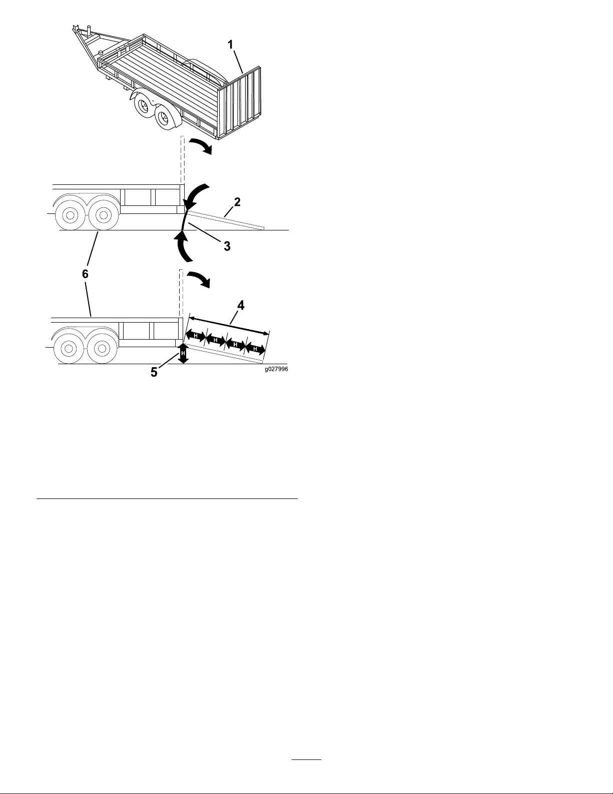
LoadingtheMachine
Useextremecautionwhenloadingorunloadingmachines
ontoatraileroratruck.Useafull-widthrampthatiswider
thanthemachineforthisprocedure.Backuprampsand
driveforwarddownramps(Figure21).
WARNING
Loadingamachineontoatrailerortruckincreases
thepossibilityoftip-overandcouldcauseserious
injuryordeath.
•Useextremecautionwhenoperatingamachine
onaramp.
•Useonlyafull-widthramp;donotuseindividual
rampsforeachsideofthemachine.
•Donotexceeda15-degreeanglebetweenthe
rampandthegroundorbetweentherampand
thetrailerortruck.
•Ensurethelengthoframpisatleastfourtimes
(4X)aslongastheheightofthetrailerortruck
bedtotheground.Thiswillensurethatramp
angledoesnotexceed15degreesonatground.
•Backuprampsanddriveforwarddownramps.
•Avoidsuddenaccelerationordecelerationwhile
drivingthemachineonarampasthiscould
causealossofcontroloratip-oversituation.
Figure21
1.Backupramps
Important:Donotusenarrowindividualrampsfor
eachsideofthemachine.
Ensuretherampislongenoughsothattheanglewiththe
grounddoesnotexceed15degrees(Figure22).Onat
ground,thisrequiresaramptobeatleastfourtimes(4X)as
longastheheightofthetrailerortruckbedtotheground.A
steeperanglemaycausemowercomponentstogetcaughtas
theunitmovesfromtheramptothetrailerortruck.Steeper
anglesmayalsocausethemachinetotiporlosecontrol.If
loadingonornearaslope,positionthetrailerortrucksothat
itisonthedownsideoftheslopeandtherampextendsup
theslope.Thiswillminimizetherampangle.
2.Driveforwarddownramps
23
Page 24
g027996
5
1
2
6
OperatingTips
UsingtheFastThrottleSetting
Forbestmowingandmaximumaircirculation,operate
theengineattheFastthrottleposition.Airisrequiredto
thoroughlycutgrassclippings,sodonotsettheheight-of-cut
solowastototallysurroundthemowerbyuncutgrass.
Alwaystrytohaveonesideofthemowerfreefromuncut
grass,whichallowsairtobedrawnintothemower.
CuttingaLawnfortheFirstTime
Cutgrassslightlylongerthannormaltoensurethatthe
cuttingheightofthemowerdoesnotscalpanyuneven
ground.However,thecuttingheightusedinthepastis
generallythebestonetouse.Whencuttinggrasslongerthan
sixinchestall,youmaywanttocutthelawntwicetoensure
anacceptablequalityofcut.
Cutting1/3oftheGrassBlade
Itisbesttocutonlyabout1/3ofthegrassblade.Cutting
morethanthatisnotrecommendedunlessgrassissparse,or
itislatefallwhengrassgrowsmoreslowly.
1.Full-widthrampinstowed
position
2.Sideviewoffull-width
rampinloadingposition
3.Notgreaterthan
15degrees
Figure22
4.Rampisatleastfourtimes
(4X)aslongastheheight
ofthetrailerortruckbed
totheground
5.H=heightofthetraileror
truckbedtotheground
6.Trailer
MowingDirection
Alternatethemowingdirectiontokeepthegrassstanding
straight.Thisalsohelpsdisperseclippingswhichenhances
decompositionandfertilization.
MowingatCorrectIntervals
Normally,mowevery4days.But,remember,grassgrowsat
differentratesatdifferenttimes.Sotomaintainthesame
cuttingheight,whichisagoodpractice,andmowmoreoften
inearlyspring.Asthegrassgrowthrateslowsinmidsummer,
mowlessfrequently.Ifyoucannotmowforanextended
period,rstmowatahighcuttingheight,thenmowagain2
dayslateratalowerheightsetting.
AvoidingCuttingTooLow
Ifthecuttingwidthofthemoweriswiderthanthemower
youpreviouslyused,raisethecuttingheighttoensurethat
uneventurfisnotcuttooshort.
CuttingLongGrass
Ifthegrassiseverallowedtogrowslightlylongerthan
normal,orifitcontainsahighdegreeofmoisture,raisethe
cuttingheighthigherthanusualandcutthegrassatthis
setting.Thencutthegrassagainusingthelower,normal
setting.
Stopping
Ifyoumuststopthemachine'sforwardmotionwhilemowing,
aclumpofgrassclippingsmaydropontoyourlawn.Toavoid
24
Page 25

this,moveontoapreviouslycutareawiththebladesengaged
oryoucandisengagethemowerdeckwhilemovingforward.
KeepingtheUndersideoftheMower
Clean
Cleanclippingsanddirtfromtheundersideofthemower
aftereachuse.Ifgrassanddirtbuildupinsidethemower,
cuttingqualitywilleventuallybecomeunsatisfactory.
MaintainingtheBlade(s)
Maintainasharpbladethroughoutthecuttingseasonbecause
asharpbladecutscleanlywithouttearingorshreddingthe
grassblades.Tearingandshreddingturnsgrassbrownat
theedges,whichslowsgrowthandincreasesthechanceof
disease.Checkthemowerbladesaftereachuseforsharpness,
andforanywearordamage.Filedownanynicksandsharpen
thebladesasnecessary.Ifabladeisdamagedorworn,replace
itimmediatelywithagenuineTororeplacementblade.
25
Page 26

Maintenance
Note:Determinetheleftandrightsidesofthemachinefromthenormaloperatingposition.
RecommendedMaintenanceSchedule(s)
MaintenanceService
Interval
Aftertherst5hours
Aftertherst50hours
Beforeeachuseordaily
Aftereachuse
Every25hours
Every100hours
Every200hours
MaintenanceProcedure
•Changetheengineoil.
•Changetheoilandltersforthehydraulicsystem,andbleedthesystem.
•Checktheengine-oillevel.
•Cleantheairintakescreen.
•Checkthecuttingblades.
•Inspectthegrassdeectorfordamage.
•Checkandcleanthefrontofthemower.
•Cleanthemowerhousing.
•Greaseallthelubricationpoints.
•Cleantheair-cleanerfoamelement(moreoftenindusty ,dirtyconditions).
•Checktirepressure.
•Checktheoillevelintheexpansiontank.
•Checkthebeltsforwear/cracks.
•Replacetheair-cleanerfoamelement(moreoftenindusty,dirtyconditions).
•Servicetheair-cleanerpaperelement(moreoftenindusty,dirtyconditions).
•Changetheengineoil(moreoftenindusty,dirtyconditions).
•Changetheoillter(moreoftenindusty,dirtyconditions).
•Checkthesparkplug(s).
•Checkthein-linefuellter.
•Replacetheair-cleanerpaperelement(moreoftenindusty,dirtyconditions).
•Replacethesparkplug(s).
•Replacethein-linefuellter.
Every400hours
Beforestorage
•Changetheoilandltersforthehydraulicsystem,andbleedthesystem.
•Chargethebatteryanddisconnectbatterycables.
•Performallmaintenanceprocedureslistedabovebeforestorage.
•Paintanychippedsurfaces.
CAUTION
Ifyouleavethekeyintheignitionswitch,someonecouldaccidentlystarttheengineandseriouslyinjure
youorotherbystanders.
Removethekeyfromtheignitionanddisconnectthewirefromthesparkplugbeforeyoudoany
maintenance.Setthewireasidesothatitdoesnotaccidentallycontactthesparkplug.
26
Page 27

Premaintenance
Lubrication
Procedures
GreasingtheBearings
RaisingtheSeat
Makesurethattheparkingbrakeisengaged,andlifttheseat
forward.
Thefollowingcomponentscanbeaccessedbyraisingtheseat:
•Serialplate
•Servicedecal
•Seat-adjustmentbolts
•Fuellter
•Batteryandbatterycables
RaisingtheFrontofthe Machine
Ifthefrontofthemachineneedstoberaised,usethevery
frontedgeasshowinFigure23.
Important:Topreventdamagetothesteering
mechanism,ensuretheveryfrontedgeofthemachine
isusedforjackingpoints.
ServiceInterval:Every25hours—Greaseallthelubrication
points.
GreaseType:No.2general-purpose,lithium-basedgrease
1.Parkthemachineonalevelsurface,anddisengagethe
blade-controlswitch.
2.Ensuretheparkingbrakeisengaged,stoptheengine,
removethekey ,andwaitforallmovingpartstostop
beforeleavingtheoperatingposition.
3.Cleanthegreasettings(Figure24andFigure25)with
arag.
Note:Makesuretoscrapeanypaintoffofthefront
ofthetting(s).
Figure23
Figure24
1.Frontcastertire
Figure25
Locatedontheseat-panunderside
1.Readtheinstructions
beforeservicingor
performingmaintenance
2.Checkthetirepressure
every25operatinghours
4.Connectagreaseguntoeachtting(Figure24and
Figure25).
5.Pumpgreaseintothettingsuntilgreasebeginsto
oozeoutofthebearings.
3.Greaseevery25operating
hours
4.Engine
27
Page 28

EngineMaintenance
g027800
g027801
g027802
ServicingtheAirCleaner
Note:Servicetheaircleanermorefrequently(everyfew
hours)ifoperatingconditionsareextremelydustyorsandy.
RemovingtheElements
1.Parkthemachineonalevelsurfaceanddisengagethe
blade-controlswitch(PTO).
2.Engagetheparkingbrake,stoptheengine,removethe
key,andwaitforallmovingpartstostopbeforeleaving
theoperatingposition.
3.Cleanaroundtheair-cleanercovertopreventdirtfrom
gettingintotheengineandcausingdamage.
4.Liftthecoverandrotatetheair-cleanerassemblyout
oftheengine(Figure26).
Figure27
ServicingtheFoamElement
ServiceInterval:Every25hours/Monthly(whichever
comesrst)—Cleantheair-cleanerfoam
element(moreoftenindusty,dirty
conditions).
Every100hours/Yearly(whichevercomes
rst)—Replacetheair-cleanerfoamelement(more
oftenindusty,dirtyconditions).
Washthefoamelementwithwaterandreplacethefoam
elementifitisdamaged.
ServicingthePaperElement
ServiceInterval:Every100hours/Yearly(whichevercomes
rst)—Servicetheair-cleanerpaper
element(moreoftenindusty,dirty
conditions).
Figure26
5.Removethefoamelementfromthepaperelement
(Figure27).
Every200hours/Every2years(whichevercomes
rst)—Replacetheair-cleanerpaperelement(more
oftenindusty,dirtyconditions).
1.Lightlytaptheelementonaatsurfacetoremovedust
anddirt.
2.Inspecttheelementfortears,anoilylm,anddamage
totheseal.
Important:Donotcleanthepaperelementwith
pressurizedairorliquids,suchassolvent,gas,
orkerosene.Replacethepaperelementifitis
damagedorcannotbecleanedthoroughly.
28
Page 29

ServicingtheEngineOil
SAE 5W -30, 10W -30
SAE 30
SYNTHETIC 5W -20, 5W -30, 10W -30
g029683
B
A
C
D
E
G029368
F
G H
I J K
OilType:Detergentoil(APIserviceSF,SG,SH,SJ,orSL)
CrankcaseCapacity:2.0L(67.6oz)
Viscosity:Seethetablebelow.
Figure28
CheckingtheEngine-OilLevel
ServiceInterval:Beforeeachuseordaily
Note:Checktheoilwhentheengineiscold.
WARNING
Contactwithhotsurfacesmaycausepersonal
injury.
Keephands,feet,face,clothing,andotherbody
partsawaythemuferandotherhotsurfaces.
Important:Donotoverllthecrankcasewithoil,
becausedamagetotheenginemayresult.Donotrun
enginewithoilbelowtheLowmark,becausetheengine
maybedamaged.
1.Parkthemachineonalevelsurface,disengagethe
blade-controlswitch,stoptheengine,engageparking
brake,andremovethekey.
2.Makesuretheengineisstopped,level,andiscool,so
theoilhashadtimetodrainintothesump.
3.Tokeepdirt,grassclippings,etc.,outoftheengine,
cleantheareaaroundtheoil-llcapanddipstickbefore
removingit(Figure29).
4.Stoptheengine,removethekey,andwaitforallmoving
partstostopbeforeleavingtheoperatingposition.
Figure29
ChangingtheEngineOilandOilFilter
ServiceInterval:Aftertherst5hours/Aftertherst
month(whichevercomesrst)—Change
theengineoil.
Every100hours/Yearly(whichevercomes
rst)—Changetheengineoil(moreoftenindusty,
dirtyconditions).
Every100hours/Yearly(whichevercomes
rst)—Changetheoillter(moreoftenindusty,dirty
conditions).
Note:Changetheengine-oilltermorefrequentlywhen
operatingconditionsareextremelydustyorsandy.
Note:Disposeoftheusedoilatarecyclingcenter.
1.Parkthemachineonalevelsurfacetoensuretheoil
drainscompletely.
2.DisengagethePTOandensuretheparkingbrakeis
engaged.
3.Stoptheengine,removethekey,andwaitforallmoving
partstostopbeforeleavingtheoperatingposition.
29
Page 30

4.Draintheengineoil.
g027799
A
B
C
D
E
F
G
H
g029570
B
A
C D
E
F
3/4
g027477
5.Changetheengineoillter(Figure31).
Figure31
Note:Ensurethattheoil-ltergaskettouchesthe
engineandthenanextra3/4turniscompleted.
6.Slowlypourapproximately80%ofthespeciedoil
intothellertubeandslowlyaddtheadditionaloilto
bringittotheFullmark(Figure32).
Figure30
30
Page 31

B
A
C
D
E
F
g027484
Figure32
B
A
g027478
B
A
g027479
Note:Duetothedeeprecessaroundthesparkplug,
blowingoutthecavitywithcompressedairisusually
themosteffectivemethodforcleaning.Thesparkplug
ismostaccessiblewhentheblowerhousingisremoved
forcleaning.
CheckingtheSparkPlug
Important:Donotcleanthesparkplug(s).Always
replacethesparkplug(s)whenithas:ablackcoating,
wornelectrodes,anoilylm,orcracks.
Ifyouseelightbrownorgrayontheinsulator,theengineis
operatingproperly .Ablackcoatingontheinsulatorusually
meanstheaircleanerisdirty.
Setthegapto0.76mm(0.030inch).
ServicingtheSparkPlug
ServiceInterval:Every100hours/Yearly(whichevercomes
rst)—Checkthesparkplug(s).
Every200hours/Every2years(whichevercomes
rst)—Replacethesparkplug(s).
Makesuretheairgapbetweenthecenterandsideelectrodes
iscorrectbeforeinstallingthesparkplug.Useaspark-plug
wrenchforremovingandinstallingthesparkplug(s)anda
gappingtool/feelergaugetocheckandadjusttheairgap.
Installanewsparkplug(s)ifnecessary.
Type:ChampionRN9YCorNGKBPR6ES
Airgap:0.76mm(0.03inch)
RemovingtheSparkPlug
1.DisengagethePTOandensuretheparkingbrakeis
engaged.
2.Stoptheengine,removethekey,andwaitforallmoving
partstostopbeforeleavingtheoperatingposition.
Figure34
Figure33
31
Page 32

InstallingtheSparkPlug
B
A
25-30 N-m
18.5-22.1 ft-lb
g027960
C
D
Note:Ifatorquewrenchisnotavailablewheninstallinga
sparkplug,installausedsparkplugan1/8–1/4turnpast
ngertightandinstallanewsparkpluga1/2turnpastnger
tight.Ensurethesparkplugistightenedwithatorquewrench
assoonaspossible.
Tightenthesparkplug(s)to25–30N-m(18.5–22.1ft-lb).
Figure35
FuelSystem
Maintenance
DANGER
Incertainconditions,gasolineisextremely
ammableandhighlyexplosive.Areorexplosion
fromgasolinecanburnyouandothersandcan
damageproperty.
•Performanyfuelrelatedmaintenancewhenthe
engineiscold.Dothisoutdoorsinanopenarea.
Wipeupanygasolinethatspills.
•Neversmokewhendraininggasoline,andstay
awayfromanopenameorwhereasparkmay
ignitethegasolinefumes.
ReplacingtheIn-LineFuel Filter
ServiceInterval:Every100hours/Yearly(whichevercomes
rst)—Checkthein-linefuellter.
Every200hours/Every2years(whichevercomes
rst)—Replacethein-linefuellter.
CleaningtheCoolingSystem
Cleantheairintakescreenfromgrassanddebrisbeforeeach
use.
1.Disengagetheblade-controlswitchandapplythe
parkingbrake.
2.Stoptheengine,removethekey,andwaitforallmoving
partstostopbeforeleavingtheoperatingposition.
3.Removetheengineshroud.
4.Cleandebrisandgrassfromtheparts.
5.Installtheengineshroud.
Neverinstalladirtylterifitisremovedfromthefuelline.
1.Parkthemachineonalevelsurfaceanddisengagethe
blade-controlswitch.
2.Ensurethebrakeisengaged,stoptheengine,remove
thekey ,andwaitforallmovingpartstostopbefore
leavingtheoperatingposition.
32
Page 33

g027939
B
A
C
D
g029685
ElectricalSystem
Maintenance
WARNING
CALIFORNIA
Proposition65Warning
Batteryposts,terminals,andrelated
accessoriescontainleadandleadcompounds,
chemicalsknowntotheStateofCalifornia
tocausecancerandreproductiveharm.
Washhandsafterhandling.
ChargingtheBattery
RemovingtheBattery
WARNING
Batteryterminalsormetaltoolscouldshortagainst
metalmachinecomponentscausingsparks.Sparks
cancausethebatterygassestoexplode,resulting
inpersonalinjury.
Figure36
•Whenremovingorinstallingthebattery,donot
allowthebatteryterminalstotouchanymetal
partsofthemachine.
•Donotallowmetaltoolstoshortbetween
thebatteryterminalsandmetalpartsofthe
machine.
1.Parkthemachineonalevelsurfaceanddisengagethe
blade-controlswitch.
2.Ensuretheparkingbrakeisengaged,stoptheengine,
removethekey ,andwaitforallmovingpartstostop
beforeleavingtheoperatingposition.
3.Raisetheseattoaccessthebattery.
4.Disconnectthenegative(black)groundcablefromthe
batterypost(Figure37).Retainallfasteners.
WARNING
Incorrectbatterycableroutingcoulddamage
themachineandcablescausingsparks.
Sparkscancausethebatterygassesto
explode,resultinginpersonalinjury.
•Alwaysdisconnectthenegative(black)
batterycablebeforedisconnectingthe
positive(red)cable.
•Alwaysconnectthepositive(red)battery
cablebeforeconnectingthenegative
(black)cable.
33
Page 34

5.Slidetherubbercoverupthepositive(red)cable.
g017701
2
3
4
5
6
7
1
Disconnectthepositive(red)cablefromthebattery
post(Figure37).Retainallfasteners.
6.Removethebatteryhold-down(Figure37)andliftthe
batteryfromthebatterytray .
Figure38
Figure37
1.Battery5.Negativebatterypost
2.Positivebatterypost6.Wingnut,washer ,andbolt
3.Bolt,washer,andnut7.Batteryhold-down
4.Terminalboot
ChargingtheBattery
ServiceInterval:Beforestorage—Chargethebatteryand
disconnectbatterycables.
1.Removethebatteryfromthechassis;refertoRemoving
theBattery.
1.Positivebatterypost
2.Negativebatterypost
3.Red(+)chargerlead
4.Black(-)chargerlead
InstallingtheBattery
1.Positionthebatteryinthetray(Figure37).
2.Installthepositive(red)batterycabletothepositive(+)
batteryterminalusingthefastenersremovedpreviously.
3.Installthenegativebatterycabletothenegative(-)
batteryterminalusingthefastenersremovedpreviously.
4.Slidetheredterminalbootontothepositive(red)
batterypost.
5.Securethebatterywiththehold-down(Figure37).
6.Lowertheseat.
2.Chargethebatteryforaminimumof1hourat6to10
amps.Donotoverchargethebattery.
3.Whenthebatteryisfullycharged,unplugthecharger
fromtheelectricaloutlet,thendisconnectthecharger
leadsfromthebatteryposts(Figure38).
34
Page 35

ServicingtheFuses
30
25
30
25
G014921
2
1
DriveSystem
Theelectricalsystemisprotectedbyfuses.Itrequires
nomaintenance;however,ifafuseblows,checkthe
component/circuitforamalfunctionorshort.
Fuse:
•MainF1-30amp,blade-type
•ChargeCircuitF2-25amp,blade-type
1.Removethescrewssecuringthecontrolpaneltothe
machine.Retainallfasteners
2.Liftthecontrolpaneuptoaccessthemainwiring
harnessandfuseblock(Figure39).
3.Toreplaceafuse,pulloutonthefusetoremoveit
(Figure39).
Maintenance
CheckingtheTirePressure
ServiceInterval:Every25hours—Checktirepressure.
Maintaintheairpressureinthefrontandreartiresas
specied.Uneventirepressurecancauseunevencut.Check
thepressureatthevalvestem(Figure40).Checkthetires
whentheyarecoldtogetthemostaccuratepressurereading.
Refertothemaximumpressuresuggestedbythetire
manufactureronthesidewallofthecasterwheeltires.
Inatethereardrivewheeltiresto90kPa(13psi).
Figure40
Figure39
1.Main-30amp
4.Returnthecontrolpaneltoitsoriginalposition.Use
thescrewsremovedpreviouslytosecurethepanelto
themachine.
2.Chargecircuit-25amp
1.Valvestem
ReleasingtheElectricBrake
Theelectricbrakereleasesbymanuallyrotatingthelinkarms
forward.Oncetheelectricbrakeisenergizedthebrakewill
reset.
Toreleasethebrake:
1.TurntheignitionkeytotheOffpositionordisconnect
thebattery.
2.Locatetheshaftswherethebrake-linkarmsare
connectedonbothsidesoftheelectricbrake(Figure
41).
3.Rotatetheshaftsforwardtoreleasethebrakes.
35
Page 36

1.Rotatebrake-linkarmforwardontheelectric-brake-control
module
2.Leftreartire
Figure41
HydraulicSystem
Maintenance
HydraulicSystemOilSpecication
OilType:ToroHYPR-OIL®500or20w-50motoroil.
SystemCapacity:approximately4.495L(152oz)witha
lterchange.
CheckingtheHydraulicOil Level
ServiceInterval:Every25hours
Checkexpansionreservoirandifnecessaryaddthespecied
oiltotheFullColdline.
1.Expansionreservoir3.Engine
2.Fullcoldline
36
Figure42
Page 37

ChangingtheHydraulic SystemOilandFilters
ServiceInterval:Aftertherst50hours
Every400hours
Important:Thebleedingprocessisrepeateduntilthe
oilremainsattheFullColdlineinthereservoirafter
purging.
can r esult in ir r epara ble dama ge to the transaxle dri v e
system.
Note:Thelterandoilarechangedatthesametime.Do
Notreuseoil.Oncethenewlterisinstalledandoilisadded
anyairinthesystemmustbepurged.
F ailur e to pr oper l y perf or m this pr ocedur e
RemovingHydraulicSystemFilters
1.Stopengine,waitforallmovingpartstostop,and
allowenginetocool.Removethekeyandengagethe
parkingbrake.
2.Raisetherearofmachineupandsupportwithjack
stands(orequivalentsupport)justhighenoughto
allowdrivewheelstoturnfreely.
Figure43
1.Jackingpoints
Figure44
Rightsideshown
1.Transaxledrive
2.Oillter
3.Filterguard
4.Carefullycleanareaaroundlters.Itisimportantthat
nodirtorcontaminationenterhydraulicsystem.
5.Placeacontainerbelowtheltertocatchtheoilthat
drainswhenthelterandventplugsareremoved.
6.Locateandremovetheventplugoneachtransmission
7.Unscrewtheltertoremoveandallowoiltodrain
fromdrivesystem.
Repeatthisprocedureforbothlters.
4.Screws
5.Ventplug
3.Locatethelterandlterguardsoneachtransaxle
drivesystem(Figure44).Removethreescrewssecuring
thelterguardandguard.
37
Page 38

InstallingtheHydraulicSystemFilters
B
A
C D
E
F
3/4
g027477
hydraulicltersandoilcanresultinirreparable
damagetothetransaxledrivesystem.
BleedingtheHydraulicSystem
1.Entertheoperator'sposition.Startengineand
movethrottlecontrolaheadto1/2throttleposition.
Disengageparkingbrake.
A.Movethebypassleversintothepushingthe
machineposition;refertoPushingtheMachine
byHand(page21).Withthebypassvalvesopen
andtheenginerunning,slowlymovethemotion
controlpedalinbothforwardandreverse(5or
6times).
B.Movethebypassleversintotheoperating
themachineposition.Withthebypassvalve
closedandtheenginerunning,slowlymovethe
traction-controlpedalinbothforwardandreverse
directions(5to6times).
C.Stoptheengineandchecktheoillevelinthe
expansionreservoir.Addthespeciedoilasuntil
itreachestheFullColdlineontheexpansion
reservoir.
1.Applyathincoatofthespeciedoilonthesurfaceof
therubbersealofeachlter.
2.Turnthelterclockwiseuntilrubbersealcontactsthe
lteradapterthentightenthelteranadditional3/4to
1fullturn.Repeatfortheotherlter
3.Installthelterguardsovereachlteraspreviously
removed.Usethethreescrewstosecurethelter
guards.
4.Verifytheventplugsareremovedbeforeaddingthe
oil(Figure44).
5.Slowlypourthespeciedoilthroughexpansion
reservoiruntiloilcomesoutofoneoftheventplug
holes.Stopandinstallthatventplug.Torquetheplug
to20.3N-m(180in-lb).
6.Continuetoaddoilthroughtheexpansionreservoir
untiloilcomesoutoftheremainingventplugholeon
thesecondtransmission.Stopandinstallthatvent
plug.Torquetheplugto20.3N-m(180in-lb).
7.Continuetoaddoilthroughtheexpansionreservoir
untilitreachestheFullColdlineontheexpansion
reservoir.
8.ProceedtotheBleedingtheHydraulicSystemsection.
Figure45
2.Repeatstep1untilalltheairiscompletelypurgedfrom
thesystem.
Whenthetransaxleoperatesatnormalnoiselevelsand
movessmoothlyforwardandreverseatnormalspeeds,
thenthetransaxleisconsideredpurged.
3.Checktheoillevelintheexpansionreservoironelast
time.AddthespeciedoilasuntilitreachestheFull
Coldlineontheexpansionreservoirifnecessary.
Important:Failuretoperformthe
the Hy draulic System
procedureafterchanging
Bleeding
38
Page 39

MowerMaintenance
G014972
1
2
3
ServicingtheCuttingBlades
Maintainsharpbladesthroughoutthecuttingseasonbecause
sharpbladescutcleanlywithouttearingorshreddingthegrass
blades.Tearingandshreddingturnsgrassbrownattheedges,
whichslowsgrowthandincreasesthechanceofdisease.
Checkthecutterbladesdailyforsharpness,andforany
wearordamage.Filedownanynicksandsharpenthe
bladesasnecessary.Ifabladeisdamagedorworn,replace
itimmediatelywithagenuineT ororeplacementblade.For
convenientsharpeningandreplacement,youmaywantto
keepextrabladesonhand.
WARNING
Awornordamagedbladecanbreak,andapiece
ofthebladecouldbethrownintotheoperator's
orbystander'sarea,resultinginseriouspersonal
injuryordeath.
•Inspectthebladeperiodicallyforwearor
damage.
•Replaceawornordamagedblade.
Figure46
1.Cuttingedge3.Wear/slotforming
2.Curvedarea
4.Damage
CheckingforBentBlades
Note:Themachinemustbeonalevelsurfaceforthe
followingprocedure.
1.Raisethemowerdecktothehighestheight-of-cut
position;alsoconsideredthe'transport'position.
2.Whilewearingthicklypaddedglovesorotheradequate
handprotectionslowlyrotatebladetobemeasured
intoapositionthatallowseffectivemeasurementof
thedistancebetweenthecuttingedgeandthelevel
surfacethemachineison.
BeforeInspectingorServicingthe
Blades
Parkthemachineonalevelsurface,disengagethe
blade-controlswitch,andensuretheparkingbrakeisengaged.
Stoptheengineandremovethekey .
InspectingtheBlades
ServiceInterval:Beforeeachuseordaily—Checkthe
cuttingblades.
1.Inspectthecuttingedges(Figure46).Iftheedges
arenotsharporhavenicks,removeandsharpenthe
blades;refertoSharpeningtheBlades.
2.Inspecttheblades,especiallythecurvedarea(Figure
46).Ifyounoticeanydamage,wear,oraslotforming
inthisarea(items3and4inFigure46),immediately
installanewblade.
Figure47
1.Deck3.Blade
2.Spindlehousing
39
Page 40

3.Measurefromthetipofthebladetotheatsurface
G014973
1
2
3
G014974
1
2
3
G014973
1
2
3
here.
Figure48
1.Blade,inpositionformeasuring
2.Levelsurface
3.Measureddistancebetweenbladeandsurface(A)
Figure50
1.Opposingbladeedge,inpositionformeasuring
2.Levelsurface
3.Secondmeasureddistancebetweenbladeandsurface(B)
WARNING
4.Rotatethesameblade180degreessothattheopposing
cuttingedgeisnowinthesameposition.
Figure49
1.Blade,sidepreviouslymeasured
2.Measurementpositionusedpreviously
3.Opposingsideofbladebeingmovedintomeasurement
position
5.Measurefromthetipofthebladetotheatsurface
here.Thevarianceshouldbenomorethan1/8inch
(3mm).
Abladethatisbentordamagedcouldbreak
apartandcouldseriouslyinjureorkillyouor
bystanders.
•Alwaysreplacebentordamagedblade
withanewblade.
•Neverleorcreatesharpnotchesinthe
edgesorsurfacesofblade.
A.IfthedifferencebetweenAandBisgreater
than1/8inch(3mm)replacethebladewitha
newblade.RefertoRemovingtheBladesand
InstallingtheBlades.
Note:Ifabentbladeisreplacedwithanewone
andthedimensionobtainedcontinuestoexceed
1/8inch(3mm),thebladespindlecouldbebent.
ContactanAuthorizedToroDealerforservice.
B.Ifthevarianceiswithinconstraints,movetothe
nextblade..
Repeatthisprocedureoneachblade.
RemovingtheBlades
Thebladesmustbereplacedifasolidobjectishit,ifthe
bladeisoutofbalance,orthebladeisbent.Toensure
optimumperformanceandcontinuedsafetyconformance
ofthemachine,usegenuineTororeplacementblades.
Replacementbladesmadebyothermanufacturersmayresult
innon-conformancewithsafetystandards.
Holdthebladeendusingaragorthickly-paddedglove.
Removethebladebolt,curvedwasher,andbladefromthe
spindleshaft(Figure51).
40
Page 41

G027833
3.Torquethebladeboltto35-65ft-lb(47-88N-m).
G005278
1
2
2
3
3
4
4
LevelingtheMowerDeck
Checktoensurethemowerdeckislevelanytimeyouinstall
themowerorwhenyouseeanunevencutonyourlawn.
Themowerdeckmustbecheckedforbentbladespriorto
leveling;anybentbladesmustberemovedandreplaced.Refer
totheCheckingforBentBlades(page39)beforecontinuing.
Themowerdeckmustbeleveledside-to-siderstthenthe
fronttorearslopecanbeadjusted.
Figure51
1.Sailareaofblade3.Curvedwasher
2.Blade4.Bladebolt
SharpeningtheBlades
1.Usealetosharpenthecuttingedgeatbothendsof
theblade(Figure52).Maintaintheoriginalangle.The
bladeretainsitsbalanceifthesameamountofmaterial
isremovedfrombothcuttingedges.
Figure52
1.Sharpenatoriginalangle
2.Checkthebalanceofthebladebyputtingitonablade
balancer(Figure53).Ifthebladestaysinahorizontal
position,thebladeisbalancedandcanbeused.Ifthe
bladeisnotbalanced,lesomemetalofftheendof
thesailareaonly(Figure52).Repeatthisprocedure
untilthebladeisbalanced.
Requirements:
•Themachinemustbeonalevelsurface.
•Allfourtiremustbeproperlyinated.RefertoChecking
theTirePressure(page35).
LevelingfromSidetoSide
1.Parkthemachineonalevelsurfaceanddisengagethe
blade-controlswitch.
2.Ensuretheparkingbrakeisengaged,stoptheengine,
removethekey ,andwaitforallmovingpartstostop
beforeleavingtheoperatingposition.
3.Settheheight-of-cutlevertomiddleposition.
4.Carefullyrotatetheblade(s)sothattheyareallside
toside(Figure54).
Figure53
1.Blade2.Balancer
InstallingtheBlades
1.Installthebladeontothespindleshaft(Figure51).
Important:Thecurvedpartoftheblademustbe
pointingupwardtowardtheinsideofthemowerto
ensurepropercutting.
2.Installthecurvedwasher(cuppedsidetowardthe
blade)andthebladebolt(Figure51).
Figure54
Mowerdeckswith3blades
1.Bladesidetoside
2.Sailareaoftheblade4.Measurefromthetipofthe
3.Outsidecuttingedges
bladetotheatsurface
here
5.Measurebetweentheoutsidecuttingedgesandthe
atsurface(Figure54).Ifbothmeasurementsarenot
within5mm(3/16inch),anadjustmentisrequired;
continuewiththisprocedure.
6.Movetotheleftsideofthemachine.
41
Page 42

7.Loosenthesidelockingnut.
G009659
1
2
3
2
3
G014634
1
2
3
8.Raiseorlowertheleftsideofthemowerdeckby
rotatingtherearnut.(Figure55).
Note:Rotatetherearnutclockwisetoraisethemower
deck;rotatetherearnutcounter-clockwisetolower
themowerdeck.
Figure56
MowerDeckswith3Blades
Figure55
1.Hangerbracket3.Rear-lockingnut
2.Side-lockingnut
9.Checktheside-to-sideadjustmentsagain.Repeatthis
procedureuntilthemeasurementsarecorrect.
10.Continuelevelingthedeckbycheckingthefront-to-rear
bladeslope;refertoAdjustingtheFront-to-RearBlade
Slope(page42).
AdjustingtheFront-to-RearBlade
Slope
1.Bladesfronttorear3.Measurefromthetipofthe
bladetotheatsurface
here
2.Outsidecuttingedges
5.Measurefromthetipofthefrontbladetotheat
surfaceandthetipoftherearbladetotheatsurface
(Figure56).Ifthefrontbladetipisnot1.6-7.9mm
(1/16-5/16inch)lowerthantherearbladetip,adjust
thefrontlocknut.
6.Toadjustthefront-to-rearbladeslope,rotatethe
adjustmentnutinthefrontofthemower(Figure57).
Checkthefront-to-rearbladelevelanytimeyouinstallthe
mower.Ifthefrontofthemowerismorethan7.9mm
(5/16inch)lowerthantherearofthemower,adjusttheblade
levelusingthefollowinginstructions:
1.Parkthemachineonalevelsurfaceanddisengagethe
blade-controlswitch.
2.Ensuretheparkingbrakeisengaged,stoptheengine,
removethekey ,andwaitforallmovingpartstostop
beforeleavingtheoperatingposition.
3.Settheheight-of-cutlevertomiddleposition.
Note:Checkandadjusttheside-to-sidebladelevel.
Ifyouhavenotcheckedthesetting;refertoLeveling
fromSidetoSide(page41).
4.Carefullyrotatethebladessotheyarefacingfrontto
rear(Figure56).
Figure57
1.Adjustingrod3.Locknut
2.Adjustingblock
7.Toraisethefrontofthemower,tightentheadjustment
nut.T olowerthefrontofthemower,loosenthe
adjustmentnut.
8.Afteradjustment,checkthefront-to-rearslopeagain.
Continueadjustingthenutuntilthefrontbladetipis
1.6-7.9mm(1/16-5/16inch)lowerthantherearblade
tip(Figure56).
9.Whenthefront-to-rearbladeslopeiscorrectcheckthe
side-to-sidelevelofthemoweragain;refertoLeveling
fromSidetoSide(page41).
42
Page 43

RemovingtheMower
G014635
1
2
3
2
2
3
G005077
1
2
2
3
1.Parkthemachineonalevelsurfaceanddisengagethe
blade-controlswitch.
2.Ensuretheparkingbrakeisengaged,stoptheengine,
removethekey ,andwaitforallmovingpartstostop
beforeleavingtheoperatingposition.
3.Lowertheheight-of-cutlevertothelowestposition.
4.Removethehairpincotterfromthefrontsupportrod
andremovetherodfromthedeckbracket(Figure
58).Carefullylowerthefrontofthemowerdeckto
theground.
Figure59
Figure58
1.Frontsupportrod3.Deckbracket
2.Lockingnut
5.Usingthemowerdeckhandles,liftthemowerdeckand
hangerbracketsclearoftherearliftrodandlowerthe
mowercarefullytotheground(Figure59andFigure
60).
1.Mowerdeck
2.Hangerbracket
6.Slidethemowerdeckrearwardtoremovethemower
beltfromtheenginepulley.
7.Slidethemowerdeckoutfromunderneaththe
machine.
Note:Retainallpartsforfutureinstallation.
3.Rearliftrod
MowerBeltMaintenance
InspectingtheBelts
ServiceInterval:Every25hours—Checkthebeltsfor
wear/cracks.
Checkthebeltsforcracks,frayededges,burnmarks,orany
otherdamage.Replacedamagedbelts.
ReplacingtheMowerBelt
Squealingwhenthebeltisrotating,bladesslippingwhen
cuttinggrass,frayedbeltedges,burnmarks,andcracksare
signsofawornmowerbelt.Replacethemowerbeltifanyof
theseconditionsareevident.
1.Parkthemachineonalevelsurfaceanddisengagethe
blade-controlswitch.
2.Ensuretheparkingbrakeisengaged,stoptheengine,
removethekey ,andwaitforallmovingpartstostop
beforeleavingtheoperatingposition.
3.Settheheight-of-cutatthelowestcuttingposition
[1-1/2inch(38mm)].
4.Usingaspringremovaltool,(Toropartno.92-5771),
removetheidlerspringfromthedeckhooktoremove
tensionontheidlerpulleyandrollthebeltoffofthe
pulleys(Figure60).
43
Page 44

WARNING
g017643
4
6
3 2 5
1 3
7
7
ReplacingtheGrassDeector
Thespringisundertensionwheninstalled
andcancausepersonalinjury.
Becarefulwhenremovingthebelt.
ServiceInterval:Beforeeachuseordaily—Inspectthegrass
deectorfordamage.
WARNING
Anuncovereddischargeopeningcouldallowthe
lawnmowertothrowobjectsintheoperator’sor
bystander’sdirectionandresultinseriousinjury.
Also,contactwiththebladecouldoccur.
Neveroperatethelawnmowerunlessyouinstalla
mulchplate,dischargedeector,orgrasscollection
system.
Inspectthegrassdeectorfordamagebeforeeachuse.
Replaceanydamagedpartsbeforeuse.
1.Disengagethespringfromthenotchinthedeector
bracketandslidetherodoutoftheweldeddeck
brackets,spring,anddischargedeector(Figure61).
Removethedamagedorworndischargedeector.
Figure60
1.Idlerpulley5.Enginepulley
2.Mowerbelt
3.Outsidepulley
4.Spring
5.Routethenewbeltaroundtheenginepulleyand
mowerpulleys(Figure60).
6.Usingaspringremovaltool,(Toropartno.92-5771),
installtheidlerspringoverthedeckhookandplacing
tensionontheidlerpulleyandmowerbelt(Figure60).
InstallingtheMower
1.Parkthemachineonalevelsurfaceanddisengagethe
2.Ensuretheparkingbrakeisengaged,stoptheengine,
3.Slidethemowerunderthemachine.
4.Lowertheheight-of-cutlevertothelowestposition.
5.Lifttherearofthemowerdeckandguidethehanger
6.Attachthefrontsupportrodtothemowerdeckwith
7.Installthemowerbeltontotheenginepulley;referto
blade-controlswitch.
removethekey ,andwaitforallmovingpartstostop
beforeleavingtheoperatingposition.
bracketsovertherearliftrod(Figure59).
theclevispinandhairpincotter(Figure58).
ReplacingtheMowerBelt(page43).
6.Springremovaltoo
7.Mowerdeckhandles
44
Page 45

g017617
1
3
2
4
5
g017618
1
3
4
2
Figure62
Figure61
1.Rod4.Deckbrackets
2.Spring5.Springinstalledoverthe
3.Deector
rod
2.Positionthenewdischargedeectorwiththebracket
endsbetweentheweldedbracketsonthedeckas
showninFigure61.
3.Installthespringontothestraightendoftherod.
Positionthespringontherodasshowninsothe
shorterspringendiscomingfromundertherodbefore
thebendandgoingovertherodasitreturnsfromthe
bend.
1.Rodandspringassembly
installed
2.Loopendofthespring
installedintothenotchin
thedeectorbracket
3.Rod,shortend,moved
behindmowerbracket
4.Shortend,retainedby
mowerbracket.
5.Securetherodandspringassemblybytwistingitsothe
shortendoftherodcanbeplacedbehindthefront
bracketweldedtothedeck(Figure62).
Important:Thegrassdeectormustbespring
loadedinthedownposition.Liftthedeectorup
totestthatitsnapstothefulldownposition.
4.Lifttheloopendofthespringandplaceitintothe
notchonthedeectorbracket(Figure62).
45
Page 46

Cleaning
G020098
2
4
1
2
3
4
CleaningundertheFrontof theMachine
ServiceInterval:Aftereachuse—Checkandcleanthefront
ofthemower.
Removedebrisunderthefrontofthemachinewith
compressedairorbyhandwithabrush(Figure63).
Note:Donotusewatertocleanunderthefrontofthe
machine,thiscancausebuildupofdebris.
Figure64
1.Washouttting3.O-ring
2.Hose
4.Lowerthemowertothelowestheight-of-cut.
5.Sitontheseatandstarttheengine.Engagethe
blade-controlswitchandletthemowerrunforoneto
threeminutes.
4.Coupling
Figure63
WashingtheUndersideofthe MowerDeck
ServiceInterval:Aftereachuse—Cleanthemowerhousing.
Important:Youcanwashthemachinewithmild
detergentandwater.Donotpressurewashthemachine.
Avoidexcessiveuseofwater,especiallynearthecontrol
panel,undertheseat,aroundtheengine,hydraulic
pumps,andmotors.
Washtheundersideofthemoweraftereachusetoprevent
grassbuildupforimprovedmulchactionandclipping
dispersal.
1.Parkthemachineonalevelsurfaceanddisengagethe
blade-controlswitch.
2.Ensuretheparkingbrakeisengaged,stoptheengine,
removethekey ,andwaitforallmovingpartstostop
beforeleavingtheoperatingposition.
3.Attachthehosecouplingtotheendofthemower
washouttting,andturnthewateronhigh(Figure64).
Note:Spreadpetroleumjellyonthewashouttting
O-ringtomakethecouplingslideoneasierandprotect
theO-ring.
6.Disengagetheblade-controlswitch,stoptheengine,
andremovetheignitionkey.Waitforallmovingparts
tostop.
7.Turnthewateroffandremovethecouplingfromthe
washouttting.
Note:Ifthemowerisnotcleanafteronewashing,
soakitandletitstandfor30minutes.Thenrepeatthe
process.
8.Runthemachineandmowerbladesagainforoneto
threeminutestoremoveexcesswater.
9.Turnoffthemowerblades.
WARNING
Abrokenormissingwashoutttingcould
exposeyouandotherstothrownobjectsor
bladecontact.Contactwithbladeorthrown
debriscancauseinjuryordeath.
•Replacebrokenormissingwashouttting
immediately,beforeusingmoweragain.
•Neverputyourhandsorfeetunderthe
mowerorthroughopeningsinthemower.
46
Page 47

Storage
CleaningandStorage
1.Disengagetheblade-controlswitch,ensuretheparking
brakeisengaged,stoptheengine,andremovethekey.
2.Removegrassclippings,dirt,andgrimefromthe
externalpartsoftheentiremachine,especiallythe
engine.Cleandirtandchafffromtheoutsideofthe
enginecylinderheadnsandblowerhousing.
Important:Youcanwashthemachinewithmild
detergentandwater.Donotpressurewashthe
machine.Avoidexcessiveuseofwater,especially
nearthecontrolpanel,undertheseat,aroundthe
engine,hydraulicpumps,andmotors.
3.Servicetheaircleaner;refertoServicingtheAir
Cleaner(page28).
4.Greaseandoilthemachine;refertoLubrication(page
27).
5.Changethecrankcaseoilandlter;refertoChanging
theEngineOilandOilFilter(page29).
14.Checktheconditionofthedriveandmowerbelts.
15.Checkandtightenallbolts,nuts,andscrews.Repairor
replaceanypartthatiswornordamaged.
16.Paintallscratchedorbaremetalsurfaces.Paintis
availablefromyourAuthorizedServiceDealer.
17.Storethemachineinaclean,drygarageorstoragearea.
Removethekeyfromtheignitionswitchandkeepit
inamemorableplace.Coverthemachinetoprotect
itandkeepitclean.
6.Checkthetirepressure;refertoCheckingtheTire
Pressure(page35).
7.Chargethebattery;refertoChargingtheBattery(page
33).
8.Checktheconditionoftheblades;refertoServicing
theCuttingBlades(page39).
9.Preparethemachineforstoragewhennon-useoccurs
over30days.Preparethemachineforstorageas
follows.
10.Addapetroleumbasedstabilizer/conditionertothe
fuelinthetank.Followthemixinginstructionsfrom
thestabilizermanufacturer.Donotuseanalcohol
basedstabilizer(ethanolormethanol).
Note:Afuelstabilizer/conditionerismosteffective
whenmixedwithfreshgasolineandusedatalltimes.
Runtheenginetodistributetheconditionedfuel
throughthefuelsystem(5minutes).
Important:Donotstorestabilizer/conditioned
gasolineover90days.
11.Removethesparkplug(s)andcheckitscondition;refer
toServicingtheSparkPlug(page31).Withthespark
plug(s)removedfromtheengine,pourtwotablespoons
ofengineoilintothesparkplughole.Usethestarter
tocranktheengineanddistributetheoilinsidethe
cylinder.Installthesparkplug(s).Donotinstallthe
wireonthesparkplug(s).
12.Cleananydirtandchafffromthetopofthemower.
13.Scrapeanyheavybuildupofgrassanddirtfromthe
undersideofthemower,thenwashthemowerwith
agardenhose.
47
Page 48

Troubleshooting
Problem
Theengineoverheats.
Thestarterdoesnotcrank.
Theenginedoesnotstart,startshard,or
failstokeeprunning.
PossibleCauseCorrectiveAction
1.Theengineloadisexcessive.1.Reducegroundspeed.
2.Theoillevelinthecrankcaseislow.2.Addoiltothecrankcase.
3.Thecoolingnsandairpassages
undertheengineblowerhousingare
plugged.
4.Theaircleanerisdirty.
5.Dirt,water,orstalefuelisinfuel
system.
1.Theblade-controlswitchisengaged.1.Movetheblade-controlswitchto
2.Thebatteryisdead.
3.Theelectricalconnectionsare
corrodedorloose.
4.Afuseisblown.4.Replacethefuse.
5.Arelayorswitchisdamaged.
1.Thefueltankisempty.1.Fillthefueltank.
2.Thechokeisnoton.
3.Theaircleanerisdirty.
4.Thesparkplugwire(s)islooseor
disconnected.
5.Thesparkplug(s)ispitted,fouled,or
thegapisincorrect.
6.Thereisdirtinfuellter .6.Replacethefuellter.
7.Dirt,water,orstalefuelisinfuel
system.
8.Thereisincorrectfuelinthefueltank.8.Drainthetankandreplacethefuelwith
9.Theoillevelinthecrankcaseislow.9.Addoiltothecrankcase.
3.Removetheobstructionfromthe
coolingnsandairpassages.
4.Cleanorreplacetheaircleaner
element.
5.ContactanAuthorizedServiceDealer
Disengaged.
2.Chargethebattery.
3.Checktheelectricalconnectionsfor
goodcontact.
5.ContactanAuthorizedServiceDealer.
2.MovethechokelevertoOn.
3.Cleanorreplacetheaircleaner
element.
4.Installthewire(s)onthesparkplug.
5.Installanew,correctlygappedspark
plug(s).
7.ContactanAuthorizedServiceDealer.
thepropertype.
Theenginelosespower.
Themachinedoesnotdrive.
1.Theengineloadisexcessive.1.Reducegroundspeed.
2.Theaircleanerisdirty.
3.Theoillevelinthecrankcaseislow.3.Addoiltothecrankcase.
4.Thecoolingnsandairpassages
undertheengineblowerhousingare
plugged.
5.Thesparkplug(s)ispitted,fouled,or
thegapisincorrect.
6.Thefueltankventisblocked.6.ContactanAuthorizedServiceDealer.
7.Thereisdirtinthefuellter.7.Replacethefuellter.
8.Dirt,water,orstalefuelisinthefuel
system.
9.Thereisincorrectfuelinthefueltank.9.Drainthetankandreplacethefuelwith
1.Thebypassvalvesareopen.
2.Thetractionbeltsareworn,loose,or
broken.
3.Thetractionbeltsareoffofthepulleys.3.ContactanAuthorizedServiceDealer.
4.Thetransmissionhasfailed.4.ContactanAuthorizedServiceDealer.
2.Cleantheaircleanerelement.
4.Removetheobstructionfromthe
coolingnsandairpassages.
5.Installanew,correctlygappedspark
plug(s).
8.ContactanAuthorizedServiceDealer.
thepropertype.
1.Closethetowvalves.
2.ContactanAuthorizedServiceDealer.
48
Page 49

Problem
PossibleCauseCorrectiveAction
Thereisabnormalvibration.
Thecuttingheightisuneven.
Thebladesdonotrotate.
1.Theenginemountingboltsareloose.1.Tightentheenginemountingbolts.
2.Theenginepulley,idlerpulley ,orblade
pulleyisloose.
3.Theenginepulleyisdamaged.
4.Thecuttingblade(s)is/arebentor
unbalanced.
5.Ablademountingboltisloose.5.Tightentheblademountingbolt.
6.Abladespindleisbent.
1.Theblade(s)isnotsharp.1.Sharpentheblade(s).
2.Acuttingblade(s)is/arebent.2.Installanewcuttingblade(s).
3.Themowerisnotlevel.
4.Ananti-scalpwheelisnotsetcorrectly.4.Adjusttheanti-scalpwheelheight.
5.Theundersideofthemowerisdirty.5.Cleantheundersideofthemower.
6.Thetirepressureisincorrect.6.Adjustthetirepressure.
7.Abladespindleisbent.
1.Thedrivebeltisworn,looseorbroken.1.Installanewdrivebelt.
2.Thedrivebeltisoffofthepulley.
3.ThePowerT ake-Off(PTO)switchor
PTOclutchisfaulty.
4.Themowerbeltisworn,loose,or
broken.
2.Tightentheappropriatepulley .
3.ContactanAuthorizedServiceDealer.
4.Installanewcuttingblade(s).
6.ContactanAuthorizedServiceDealer.
3.Levelthemowerfromside-to-sideand
front-to-rear.
7.ContactanAuthorizedServiceDealer.
2.Installthedrivebeltandcheckthe
adjustingshaftsandbeltguidesforthe
correctposition.
3.ContactanAuthorizedServiceDealer.
4.Installanewmowerbelt.
49
Page 50

Schematics
ElectricalDiagram(Rev .A)
50
Page 51

Notes:
51
Page 52

TheToroTotalCoverageWarranty
LimitedWarranty(seewarrantyperiodsbelow)
TimeCutter
and
TITAN
Mowers
ConditionsandProductsCovered
TheT oroCompanyanditsafliate,ToroWarrantyCompany ,pursuanttoan
agreementbetweenthem,jointlypromisetotheoriginalpurchasertorepair
theT oroProductslistedbelowifdefectiveinmaterialsorworkmanship.
Thefollowingtimeperiodsapplyfromthedateofpurchasebytheoriginal
owner:
ProductsWarrantyPeriod
TimeCutterandMXMowers
•Engines
1
Residentialuse
—ResidentialuseKawasaki–3years
2
–3years
Kohler–3years
Toro–3years
TimeCutterandMXMowersCommercialuse30days
•Engines
1
—Commercialuse
Kawasaki–3years
Kohler–90days
Toro–90days
TITANMowers–Residentialor
Commercialuse
•Engines
1
—Residentialor
Commercialuse
•Frame
TITANMX5400andMX600Mowers
–ResidentialorCommercialuse
•Engines
1
—Residentialor
Commercialuse
•Frame
3yearsor300hours
Kawasaki–3years
Lifetime(originalowneronly)
4yearsor400hours
Kawasaki–3years
Lifetime(originalowneronly)
3
4
3
4
AllMowers
•Attachments1year
•Battery90daysPartsandLabor
1yearPartsonly
•BeltsandTires90days
1
SomeenginesusedonToroProductsarewarrantedbytheenginemanufacturer .
2
Residentialusemeansuseoftheproductonthesamelotasyourhome.Useatmorethanone
locationisconsideredcommercialuseandthecommercialusewarrantywouldapply.
3
Whicheveroccursrst.
4
LifetimeFrameW arranty-Ifthemainframe,consistingofthepartsweldedtogethertoformthe
tractorstructurethatothercomponentssuchastheenginearesecuredto,cracksorbreaksin
normaluse,itwillberepairedorreplaced,atToro'soption,underwarrantyatnocostforpartsand
labor.Framefailureduetomisuseorabuseandfailureorrepairrequiredduetorustorcorrosion
arenotcovered.
Warrantymaybedeniedifthehourmeterisdisconnected,altered,or
showssignsofbeingtamperedwith.
OwnerResponsibilities
YoumustmaintainyourToroProductbyfollowingthemaintenance
proceduresdescribedintheOperator'sManual.Suchroutinemaintenance,
whetherperformedbyadealerorbyyou,isatyourexpense.
InstructionsforObtainingWarrantyService
IfyouthinkthatyourT oroProductcontainsadefectinmaterialsor
workmanship,followthisprocedure:
1.ContactanyAuthorizedT oroServiceDealertoarrangeserviceattheir
dealership.T olocateadealerconvenienttoyou,refertotheYellow
Pagesofyourtelephonedirectory(lookunder“LawnMowers”)or
accessourwebsiteatwww.T oro.com.Youmayalsocallthenumbers
listedinitem#3tousethe24-hourT oroDealerlocatorsystem.
2.Bringtheproductandyourproofofpurchase(salesreceipt)tothe
ServiceDealer.Thedealerwilldiagnosetheproblemanddetermineif
itiscoveredunderwarranty.
3.IfforanyreasonyouaredissatisedwiththeServiceDealer’s
analysisorwiththeassistanceprovided,contactusat:
CustomerCareDepartment,RLCDivision
ToroWarrantyCompany
811 1LyndaleAvenueSouth
Bloomington,MN55420-1196
Tollfreeat866-216-6029(U.S.customers)
Tollfreeat866-216-6030(Canadiancustomers)
ItemsandConditionsNotCovered
Thereisnootherexpresswarrantyexceptforspecialemissionsystem
coverageandenginewarrantycoverageonsomeproducts.Thisexpress
warrantydoesnotcoverthefollowing:
•Costofregularmaintenanceserviceorparts,suchaslters,fuel,
lubricants,oilchanges,sparkplugs,airltersbladesharpeningorworn
blades,cable/linkageadjustments,orbrakeandclutchadjustments
•Componentsfailingduetonormalwear
•Anyproductorpartwhichhasbeenalteredormisusedorneglected
andrequiresreplacementorrepairduetoaccidentsorlackofproper
maintenance
•Pickupanddeliverycharges
•RepairsorattemptedrepairsbyanyoneotherthananAuthorizedToro
ServiceDealer
•Repairsnecessaryduetofailuretofollowrecommendedfuel
procedure(consultOperator'sManualformoredetails)
–Removingcontaminantsfromthefuelsystemisnotcovered
–Useofoldfuel(morethanonemonthold)orfuelwhichcontains
morethan10%ethanolormorethat15%MTBE
–Failuretodrainthefuelsystempriortoanyperiodofnon-use
overonemonth
GeneralConditions
AllrepairscoveredbythesewarrantiesmustbeperformedbyanAuthorized
ToroServiceDealerusingT oroapprovedreplacementparts.
NeitherTheToroCompanynorToroWarrantyCompanyisliablefor
indirect,incidentalorconsequentialdamagesinconnectionwiththe
useoftheToroProductscoveredbythiswarranty,includingany
costorexpenseofprovidingsubstituteequipmentorserviceduring
reasonableperiodsofmalfunctionornon-usependingcompletionof
repairsunderthiswarranty.
Allimpliedwarrantiesofmerchantability(thattheproductistfor
ordinaryuse)andtnessforuse(thattheproductistforaparticular
purpose)arelimitedtothedurationoftheexpresswarranty.
Somestatesdonotallowexclusionsofincidentalorconsequential
damages,orlimitationsonhowlonganimpliedwarrantylasts,sothe
aboveexclusionsandlimitationsmaynotapplytoyou.
Thiswarrantygivesyouspeciclegalrights,andyoumayalsohaveother
rightswhichvaryfromstatetostate.
CountriesOtherthantheUnitedStatesorCanada
CustomerswhohavepurchasedT oroproductsoutsidetheUnitedStatesorCanadashouldcontacttheirT oroDistributor(Dealer)toobtainguarantee
policiesforyourcountry,province,orstate.IfforanyreasonyouaredissatisedwithyourDistributor'sserviceorhavedifcultyobtainingguarantee
information,contacttheT oroimporter.Ifallotherremediesfail,youmaycontactusatT oroWarrantyCompany.
AustralianConsumerLaw:AustraliancustomerswillnddetailsrelatingtotheAustralianConsumerLaweitherinsidetheboxoratyourlocalT oro
Dealer.
374-0258RevE
 Loading...